EP1596213A1 - Electronic monitoring device for multi-part electric energy storage unit - Google Patents
Electronic monitoring device for multi-part electric energy storage unit Download PDFInfo
- Publication number
- EP1596213A1 EP1596213A1 EP05016523A EP05016523A EP1596213A1 EP 1596213 A1 EP1596213 A1 EP 1596213A1 EP 05016523 A EP05016523 A EP 05016523A EP 05016523 A EP05016523 A EP 05016523A EP 1596213 A1 EP1596213 A1 EP 1596213A1
- Authority
- EP
- European Patent Office
- Prior art keywords
- measuring
- monitoring device
- electronic monitoring
- further characterized
- measuring modules
- Prior art date
- Legal status (The legal status is an assumption and is not a legal conclusion. Google has not performed a legal analysis and makes no representation as to the accuracy of the status listed.)
- Granted
Links
Images

Classifications
-
- G—PHYSICS
- G01—MEASURING; TESTING
- G01R—MEASURING ELECTRIC VARIABLES; MEASURING MAGNETIC VARIABLES
- G01R19/00—Arrangements for measuring currents or voltages or for indicating presence or sign thereof
- G01R19/165—Indicating that current or voltage is either above or below a predetermined value or within or outside a predetermined range of values
- G01R19/16533—Indicating that current or voltage is either above or below a predetermined value or within or outside a predetermined range of values characterised by the application
- G01R19/16538—Indicating that current or voltage is either above or below a predetermined value or within or outside a predetermined range of values characterised by the application in AC or DC supplies
- G01R19/16542—Indicating that current or voltage is either above or below a predetermined value or within or outside a predetermined range of values characterised by the application in AC or DC supplies for batteries
-
- G—PHYSICS
- G01—MEASURING; TESTING
- G01R—MEASURING ELECTRIC VARIABLES; MEASURING MAGNETIC VARIABLES
- G01R31/00—Arrangements for testing electric properties; Arrangements for locating electric faults; Arrangements for electrical testing characterised by what is being tested not provided for elsewhere
- G01R31/36—Arrangements for testing, measuring or monitoring the electrical condition of accumulators or electric batteries, e.g. capacity or state of charge [SoC]
- G01R31/396—Acquisition or processing of data for testing or for monitoring individual cells or groups of cells within a battery
Definitions
- the invention relates to an electronic monitoring device for one of several consecutively connected Storage units existing electrical energy storage, especially for a multi-cell or multi-block battery, wherein the monitoring device a corresponding Number of measurement modules included, respectively one of the memory units are assigned and at least a memory state indicator on the associated Measure storage unit.
- electrical energy storage in addition to mere stores, like batteries, also energy producers be understood that from non-electrical, stored Energy, e.g. mechanical or chemical energy, electrical Generate energy, e.g. Fuel cell systems.
- Such monitoring devices are used for monitoring the state of the individual blocks or cells of the electrical Energy storage, such as a traction battery of a Motor vehicle with electric or hybrid drive or a Fuel cell stack e.g. in a fuel cell vehicle.
- Typical monitored, for the memory state Indicative measures are in particular those of the respective Storage unit provided electrical voltage as well as the temperature and pressure in the storage unit.
- the monitoring serves to determine different Charges of the storage units due Uneven self-discharge and aging of the serial switched storage units, so that appropriate appropriate Countermeasures can be taken, e.g. one Charge transfer between storage units to their state of charge to hold at approximately the same level and so on avoid the total capacity of the electric energy storage determined by the "worst" storage unit becomes.
- a monitoring device of the type mentioned is described in the patent DE 195 03 917 C2.
- the individual measuring modules to one connected as a ring, serial data bus connected to which also a central data processing unit coupled is.
- the measurement data information is provided by the measurement module directed to measurement module in the form of measurement data packets via the ring, where each measurement module of each measurement packet the takes from him needed information and the measurement data package his own measurement data, e.g. about tension and Temperature of the associated storage unit, adds.
- the central data processing unit the measurement data for Determining the state of the individual storage units and thus evaluate the entire electrical energy storage.
- the invention is the provision as a technical problem an electronic monitoring device of the beginning mentioned type, the comparatively little Cabling and control effort required and reliable Statements about the state of the energy storage based the detection of one or more corresponding Measured variables allows.
- the invention solves this problem by providing an electronic monitoring device with the features of claim 1.
- the monitoring device according to the invention requires relatively little cabling and allows at least the determination of in general in particular interesting, for the state of the electrical energy storage indicative extremal values of the used quantities.
- the monitoring device is characterized in particular by the fact that the measuring modules parallel to one common signal connection are coupled and their Meßierenza condition and parallel give to the signal line that thereby on this formed total measured quantity information an evaluable, includes associated extremal value measure information.
- These Device does not require separate signal connections between every two measuring modules and no separate evaluation procedures in the measuring modules. Rather, the evaluation is done automatically by overlaying the measured quantity information of the different measurement modules on the common Signal line.
- the measurement modules can run without runtime errors be triggered at the same time.
- this variant are the measuring modules according to claim 2 via a capacitance or inductance and thus galvanically decoupled connected to the common signal line.
- the measurement modules by operating mode control signals between an activated and a deactivated state, whereby their power consumption in the deactivated state minimized is.
- the control signals can vary depending on the system variant the measuring modules on a common signal line in parallel fed or sequentially from one to the next Measuring module are passed on. Using these operating mode control signals can not currently needed Measuring modules energy-saving in deactivated state being held.
- the measurement modules by evaluation mode control signals between various evaluation modes switchable, e.g. between one Rating in terms of maximum or minimum of each Measured variable or between ratings of different Metrics. This allows these different measurement information at different times on the same Signal line are provided.
- the measuring modules selectively into active and passive measuring modules be divided, among active measuring modules such with fully activated features and under passive Measuring modules are understood to be those that are so far in readiness are held, that they forward received signals can, e.g. that of an adjacent measurement module transmitted parameter information, but no change such merely forwarded signals due to own Make measured values.
- active measuring modules such with fully activated features
- passive Measuring modules are understood to be those that are so far in readiness are held, that they forward received signals can, e.g. that of an adjacent measurement module transmitted parameter information, but no change such merely forwarded signals due to own Make measured values.
- This can be with the system variant with sequential forwarding and evaluation of Measured variable information Select any measuring modules that active in obtaining the weighted quantity information take part.
- the measurement signal in the form of a pulse width modulated signal, whose pulse width represents the associated measured variable value, delivered from the measuring modules.
- a measurement signal conditioning provided in such a way that the respective measuring signal consists of a pulse, the delayed by a time dependent on the respective measured value is sent. This type of signal also allows very much simple extremal value determinations.
- the measurement signal as a constant current signal, also allows a simple Extremalwertbetician.
- a dissipative State of charge adjustment by the measuring modules respectively contain an electrical resistance across the storage units with too high detected state of charge so far can be discharged that the maximum charge state difference between the storage units a predefinable Tolerance value does not exceed.
- FIG. 1 shows schematically a battery B consisting of a plurality of series-connected single cells B 1 , B 2 ,..., B n , which can serve, for example, as a traction battery in an electric vehicle or a vehicle with hybrid drive.
- Each battery cell B 1 , ..., B n is assigned a measuring module M 1 ,..., M n .
- Each measuring module M 1 ,..., M n senses one or more measured variables indicative of the memory state of its associated battery cell, such as voltage, temperature and pressure, for which purpose it is connected to the latter via corresponding measuring lines 1.
- the measuring modules M 1 ,..., M n are interconnected via a serial signal connection SV, the serial signal connection SV in the example shown a trigger line pair TR H , TR R , a voltage signal line pair SP min , SP max and a temperature signal line pair TE min , TE max includes.
- the trigger line pair consisting of a trigger signal outgoing line TR H, via which a trigger signal successively n from the last measurement module M is directed to the first measurement module M 1, and a trigger signal return line TR R, which is connected on the first measurement module M 1 with the outgoing line TR H is as symbolized by a line loop TR S , and from there back to the last measurement module M n .
- An associated trigger circuit of conventional type is coupled to the trigger line pair TR H , TR R in each measurement module M 1 ,..., M n which, upon receipt of a corresponding trigger signal, activates the measurement module to perform a measurement and evaluation process.
- the measurement modules M 1 ,..., M n for carrying out the measurement and evaluation processes are designed such that the maximum value and the minimum value of the voltages and the temperatures of the individual battery cells B 1 . ..., B n can be determined.
- the four extreme values determined in this way are available on the corresponding signal lines at the associated output of the first measuring module M 1 , ie the minimum voltage value U min on the voltage signal line SP min , the maximum voltage value U max on the voltage signal line SP max , the minimum temperature value T min on the temperature signal line TE min and the maximum temperature value T max on the temperature signal line TE max .
- the determination of only a part of these four extreme values and / or the additional determination of corresponding extreme values for the pressure in the respective battery cell can be provided.
- other parameters indicative of the memory state of the individual battery cells B 1 ,..., B n can also be monitored via the measuring module chain M 1 ,..., M n , ie from the measuring modules M 1 , ..., M n corresponding measured variable information are supplied.
- the determination of the extreme values is carried out by successively obtaining the measured values for voltage and temperature of the respective battery cell B 1 ,..., B n through the associated measuring module M 1 ,..., M n , suitable evaluation of the own measured values with that of a preceding one Measuring module received voltage or temperature information and forwarding the weighted voltage or temperature information to the next measurement module.
- the following procedure is implemented in the measurement modules M 1 ,..., M n .
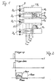
- a trigger signal "trigger up" as shown in the top diagram of Fig.
- the first measuring module M 1 begins to detect the voltage and temperature of the first battery cell B 1 . It then forwards this information to the second measuring module M 2 both as a minimum and also as a maximum voltage value or temperature value.
- the second measuring module M 2 receives this measured variable information and in turn measures voltage and temperature of the second battery cell B 2 .
- the third measuring module M 3 in turn measures the voltage and temperature of the third battery cell B 3 and compares the self-measured voltage value on the one hand with the previous minimum voltage value U min fed to it and on the other hand with the previous maximum voltage value U max applied to it . From the first-mentioned minimum value comparison, the smaller value is forwarded to the next measuring module as the current minimum voltage value. From the last-mentioned maximum value comparison, the larger value is passed on to the next measuring module as the current maximum voltage value. The same applies to the other parameter, the temperature.
- the four extremal value information U min , U max , T min , T max are received by the respective previous measurement module, evaluated according to their own measured values and forwarded to the next measurement module as such updated measurement information until finally the last measurement module M n for the Entity of the individual battery cells B 1 , ..., B n valid voltage and temperature extremes U min , U max , T min , T max outputs, for example, to supply them to the monitoring control unit.
- such a compensation of the trigger signal propagation time can also be achieved by activating the measurement modules M 1 ,..., M n already with the fed-in trigger signal "Trigger up", but then the voltage and temperature measurement information at the last triggered measurement module at the trigger signal feed point be removed opposite end of the measuring module chain.
- a simple extremal value evaluation of the measurement signal information can be achieved when using pulse-width-modulated measurement signals whose pulse width represents the associated measured value. This is illustrated for the voltage signal in the lower diagram of FIG. 2. There, accordingly, the voltage minimum value signal is shown by a solid line in a pulse width ⁇ t min , which represents the minimum voltage value U min . In the same way, the dotted line voltage maximum value signal is shown in a width ⁇ t max representing the maximum voltage value U max .
- the minimum value evaluation can then take place in the respective measuring module by simply ANDing the own measured value with the previously valid minimum value supplied by the previous measuring module, the result of which represents the newly applicable minimum value, ie the narrower of the two compared signals is selected. In the same way, the maximum value evaluation can be realized by simply ORing the own measured value with the supplied, previously valid maximum value, ie, the respectively wider one of the two compared signals is selected.
- the measuring speed for one measuring cycle is in use such pulse width modulated measurement signals primarily depending on the product of the maximum occurring pulse width with the number of modules n.
- pulse width modulated Measuring signals can be an error addition when forwarding the measured variable information from one to avoid the next measurement module, it just adds up Time differences.
- the measurement value information can also be forwarded and evaluated simply as analog measurement variable information, in particular via extremal values of the observed measurement variables, in the measurement module chain.
- the measured value information can be serially evaluated and forwarded.
- a general advantage of the serial connection of the measuring modules M 1 ,..., M n via the serial signal connection SV is that the measuring modules M 1 ,..., M n do not have to be designed to be voltage-proof.
- a further alternative option for configuring the evaluated and forwarded measured variable information is to use a pulse with a constant pulse width as the measuring signal, which is generated at a time dependent on the measured value to be coded, ie delayed by a time dependent on the measured value relative to a reference time.
- This variant allows the transmission of both a maximum value and a minimum value on a common transmission line without a coded trigger signal in which, for example, the minimum value corresponds to the earliest pulse and the maximum value corresponds to the latest pulse and intervening pulses are not forwarded in each case. It then suffices to have a respective OR comparison between the own measurement signal with the received earliest and the received latest pulse for evaluation with regard to minimum value and maximum value of the respective measurement variable, such as voltage, temperature or pressure. It is only necessary to adjust the constant pulse width between the measuring modules, M 1 ,..., M n .
- the measuring module M 1 , ..., M n each contain a corresponding A / D converter and in the signal evaluation part of the monitoring device, a suitable conventional digital signal processing is implemented.
- each measuring module M 1 ,..., M n is preferably supplied by the associated battery cell B 1 ,..., B n .
- the forwarding of a rating mode control signal can be provided with which the measurement modules M 1 ,..., M n can be switched between different evaluation modes, for example between a rating for maximum voltage during charging operations and a rating for minimum voltage during Unloading operations or alternately between a pressure and a temperature rating or between any other possible rating types. If necessary, then a single measuring signal line is sufficient, via which the measured variable information associated with the respectively active evaluation mode is transmitted.
- the passage of a selection control signal through the measuring module chain can be provided, with which the correspondingly designed measuring modules M 1 ,..., M n can be switched between an actively evaluating state and a passively remaining, merely forwarding state.
- any desired subset of measuring modules can be selected from the measuring module chain whose measured values are used to obtain the corresponding measured quantity information, while the other measuring modules only forward the received measured quantity information unchanged.
- minimum values and / or maximum values of a measured variable for an arbitrary subset of the battery cells B 1 ,..., B n can be determined.
- a parallel coupling of the measuring modules M 1 ,..., M n to a common signal connection SV ' is provided from one or more signal lines.
- the measured variable information and, if appropriate, the trigger and / or control signals are not passed on from one to the next measuring module, but placed in parallel on the common signal connection SV. This can be done for the encoded measured variable information, for example as a voltage jump, which is placed by the respective measuring module on the common signal line.
- Another possible signal conditioning is to place the measurement signal as a constant current signal on the common associated signal line, which can act as a sum line by being terminated with a resistance to one pole of the battery B, in which case the current represents the measured value.
- the variant with a common, parallel signal connection of the measuring modules M 1 ,..., M n is particularly suitable for determining the minimum value and the maximum value of a respective measured variable, without requiring an AND or OR evaluation in the individual measuring modules , If, for example, a measurement signal coding is used as the pulse-width-modulated signal, the maximum value results simply from the pulse width of the total signal on the common signal line to which the measurement modules M 1 ,..., M n output their pulse-width-modulated signals.
- the measuring modules M 1 ,..., M n can be triggered simultaneously with this type of system without a runtime error.
- the capacity used for a galvanic decoupling may possibly already be realized by a conductor track. Incidentally, for this system type with a common signal connection, the corresponding properties and advantages apply, as indicated above for the system type of FIG. 1 with serial signal connection.
- each measuring module M 1 ,..., M n contains the corresponding resistor R, which can be controllably coupled to the battery cell in question in parallel therewith, and an associated discharge control circuit 2.
- Its resistance value is primarily determined by the difference between the self-discharge characteristics of all the battery cells B 1 , ..., B n and the time duration within which a maximum charge state difference is to be compensated. A lower limit of the resistance value may be given by a maximum allowed local heating. Dissipation loss in high charge throughput applications with small capacity batteries adds only insignificantly to the usual, other losses and is therefore tolerable.
- the respective measuring module knows whether it has to discharge its associated battery cell or not, the previously determined information about the minimum voltage value U min is made available to all measuring modules M 1 ,..., M n , in the example of FIG. that it is successively forwarded from the last measuring module M n to the other measuring modules up to the first measuring module M 1 .
- Each measuring module M 1 ,..., M n then compares the minimum voltage value U min with its own measured voltage value of the associated battery cell B 1 ,..., B n and activates the dissipative discharging process if its own voltage value is more than a predetermined one Distance above the minimum voltage value U min is.
- the already required trigger pulse or the trigger signal connection TR H , TR R can be used in an advantageous realization.
- the predetermined minimum value which represents the tolerance band in which all cell charge states should lie, can be added to the minimum voltage value, so that each measurement module M 1 ,..., M n only has its own voltage measurement value via the trigger line TR H , TR R must compare minimum transmitted voltage U min to decide whether it makes a dissipative discharge of its cell.
Abstract
Description
Die Erfindung bezieht sich auf eine elektronische Überwachungseinrichtung für einen aus mehreren hintereinander geschalteten Speichereinheiten bestehenden elektrischen Energiespeicher, insbesondere für eine Mehrzellen- oder Mehrblock-Batterie, wobei die Überwachungseinrichtung eine entsprechende Anzahl von Messmodulen beinhaltet, die jeweils einer der Speichereinheiten zugeordnet sind und wenigstens eine speicherzustandsindikative Messgröße an der zugeordneten Speichereinheit messen. Der Einfachkeit halber sollen vorliegend unter dem Begriff "elektrischer Energiespeicher" neben bloßen Speichern, wie Batterien, auch Energieerzeuger verstanden werden, die aus nicht-elektrischer, gespeicherter Energie, z.B. mechanischer oder chemischer Energie, elektrische Energie erzeugen, z.B. Brennstoffzellensysteme.The invention relates to an electronic monitoring device for one of several consecutively connected Storage units existing electrical energy storage, especially for a multi-cell or multi-block battery, wherein the monitoring device a corresponding Number of measurement modules included, respectively one of the memory units are assigned and at least a memory state indicator on the associated Measure storage unit. For the sake of simplicity in this case under the term "electrical energy storage" in addition to mere stores, like batteries, also energy producers be understood that from non-electrical, stored Energy, e.g. mechanical or chemical energy, electrical Generate energy, e.g. Fuel cell systems.
Derartige Überwachungseinrichtungen dienen zur Überwachung des Zustands der einzelnen Blöcke oder Zellen des elektrischen Energiespeichers, wie einer Traktionsbatterie eines Kraftfahrzeugs mit Elektro- oder Hybridantrieb oder eines Brennstoffzellenstapels z.B. in einem Brennstoffzellenfahrzeug. Typische überwachte, für den Speicherzustand indikative Messgrößen sind insbesondere die von der jeweiligen Speichereinheit bereitgestellte elektrische Spannung sowie die Temperatur und der Druck in der Speichereinheit. Die Überwachung dient unter anderem der Feststellung unterschiedlicher Ladezustände der Speichereinheiten aufgrund ungleichmäßiger Selbstentladung und Alterung der seriell geschalteten Speichereinheiten, so dass gegebenenfalls geeignete Gegenmaßnahmen ergriffen werden können, z.B. ein Ladungstransfer zwischen Speichereinheiten, um deren Ladezustand auf annähernd gleichem Niveau zu halten und so zu vermeiden, dass die Gesamtkapazität des elektrischen Energiespeichers von der "schlechtesten" Speichereinheit bestimmt wird.Such monitoring devices are used for monitoring the state of the individual blocks or cells of the electrical Energy storage, such as a traction battery of a Motor vehicle with electric or hybrid drive or a Fuel cell stack e.g. in a fuel cell vehicle. Typical monitored, for the memory state Indicative measures are in particular those of the respective Storage unit provided electrical voltage as well as the temperature and pressure in the storage unit. Among other things, the monitoring serves to determine different Charges of the storage units due Uneven self-discharge and aging of the serial switched storage units, so that appropriate appropriate Countermeasures can be taken, e.g. one Charge transfer between storage units to their state of charge to hold at approximately the same level and so on avoid the total capacity of the electric energy storage determined by the "worst" storage unit becomes.
Eine Überwachungseinrichtung der eingangs genannten Art ist in der Patentschrift DE 195 03 917 C2 beschrieben. Bei der dortigen Einrichtung sind die einzelnen Messmodule an einen als Ring ausgelegten, seriellen Datenbus angeschlossen, an den auch eine zentrale Datenverarbeitungseinheit angekoppelt ist. Die Messdateninformationen werden von Messmodul zu Messmodul in Form von Messdatenpaketen über den Ring geleitet, wobei jedes Messmodul von jedem Messdatenpaket die von ihm benötigten Informationen entnimmt und dem Messdatenpaket seine eigenen Messdaten, z.B. über Spannung und Temperatur der zugehörigen Speichereinheit, hinzufügt. Die zentrale Datenverarbeitungseinheit kann die Messdaten zur Bestimmung des Zustands der einzelnen Speichereinheiten und damit des gesamten elektrischen Energiespeichers auswerten.A monitoring device of the type mentioned is described in the patent DE 195 03 917 C2. In the local institution, the individual measuring modules to one connected as a ring, serial data bus connected to which also a central data processing unit coupled is. The measurement data information is provided by the measurement module directed to measurement module in the form of measurement data packets via the ring, where each measurement module of each measurement packet the takes from him needed information and the measurement data package his own measurement data, e.g. about tension and Temperature of the associated storage unit, adds. The central data processing unit, the measurement data for Determining the state of the individual storage units and thus evaluate the entire electrical energy storage.
Bei einem weiteren Typ gattungsgemäßer Batterieüberwachungseinrichtungen sind die den einzelnen Speichereinheiten zugeordneten Messmodule parallel an eine gemeinsame Signalverbindung angekoppelt. Bei einer in der Offenlegungsschrift EP 0 277 321 A1 beschriebenen derartigen Einrichtung übertragen die Messmodule nacheinander nach Aufruf ihre Messdaten zu einer zentralen Auswerteeinheit.In another type of generic battery monitoring devices are the individual storage units assigned measuring modules in parallel to a common signal connection coupled. In one in the published patent application EP 0 277 321 A1 described such device the measuring modules transmit their successively after calling their Measurement data to a central evaluation unit.
Der Erfindung liegt als technisches Problem die Bereitstellung einer elektronischen Überwachungseinrichtung der eingangs genannten Art zugrunde, die vergleichsweise wenig Verkabelungs- und Steuerungsaufwand erfordert und zuverlässige Aussagen über den Zustand des Energiespeichers anhand der Erfassung einer oder mehrerer entsprechender Messgrößen ermöglicht. The invention is the provision as a technical problem an electronic monitoring device of the beginning mentioned type, the comparatively little Cabling and control effort required and reliable Statements about the state of the energy storage based the detection of one or more corresponding Measured variables allows.
Die Erfindung löst dieses Problem durch die Bereitstellung
einer elektronischen Überwachungseinrichtung mit den Merkmalen
des Anspruchs 1. Die erfindungsgemäße Überwachungseinrichtung
erfordert relativ wenig Verkabelungsaufwand und
erlaubt mindestens die Bestimmung von im allgemeinen besonders
interessierenden, für den Zustand des elektrischen Energiespeichers
indikativen Extremalwerten des oder der
verwendeten Messgrößen.The invention solves this problem by providing
an electronic monitoring device with the features
of
Die Überwachungseinrichtung nach Anspruch 1 zeichnet sich
speziell dadurch aus, dass die Messmodule parallel an eine
gemeinsame Signalverbindung angekoppelt sind und ihre Meßgrößeninformationen
dergestalt konditionieren und parallel
auf die Signalleitung geben, dass die dadurch auf dieser
gebildete Gesamt-Messgrößeninformation eine auswertbare,
zugehörige Extremalwert-Messgrößeninformation enthält. Diese
Einrichtung erfordert keine separaten Signalverbindungen
zwischen je zwei Messmodulen und keine separaten Bewertungsvorgänge
in den Messmodulen. Vielmehr erfolgt die Bewertung
automatisch durch die Überlagerung der Messgrößeninformationen
der verschiedenen Messmodule auf der gemeinsamen
Signalleitung. Die Messmodule können ohne Laufzeitfehler
gleichzeitig getriggert werden. In weiterer Ausgestaltung
dieser Variante sind die Messmodule gemäß Anspruch
2 über eine Kapazität oder Induktivität und damit
galvanisch entkoppelt an die gemeinsame Signalleitung angeschlossen.The monitoring device according to
In einer Weiterbildung der Erfindung nach Anspruch 3 sind die Messmodule durch Betriebsmodus-Steuersignale zwischen einem aktivierten und einem deaktivierten Zustand umschaltbar, wobei ihr Stromverbrauch im deaktivierten Zustand minimiert ist. Die Steuersignale können je nach Systemvariante den Messmodulen auf einer gemeinsamen Signalleitung parallel zugeführt oder sequentiell von einem zum nächsten Messmodul weitergereicht werden. Mit Hilfe dieser Betriebsmodus-Steuersignale können die momentan jeweils nicht benötigten Messmodule energiesparend im deaktivierten Zustand gehalten werden.In a further development of the invention according to claim 3 the measurement modules by operating mode control signals between an activated and a deactivated state, whereby their power consumption in the deactivated state minimized is. The control signals can vary depending on the system variant the measuring modules on a common signal line in parallel fed or sequentially from one to the next Measuring module are passed on. Using these operating mode control signals can not currently needed Measuring modules energy-saving in deactivated state being held.
In einer Weiterbildung der Erfindung nach Anspruch 4 sind die Messmodule durch Bewertungsmodus-Steuersignale zwischen verschiedenen Bewertungsmodi umschaltbar, z.B. zwischen einer Bewertung hinsichtlich Maximum oder Minimum einer jeweiligen Messgröße oder zwischen Bewertungen unterschiedlicher Messgrößen. Dadurch können diese verschiedenen Messgrößeninformationen zu unterschiedlichen Zeiten auf derselben Signalleitung bereitgestellt werden.In a further development of the invention according to claim 4 the measurement modules by evaluation mode control signals between various evaluation modes switchable, e.g. between one Rating in terms of maximum or minimum of each Measured variable or between ratings of different Metrics. This allows these different measurement information at different times on the same Signal line are provided.
In einer Weiterbildung der Erfindung nach Anspruch 5 können die Messmodule selektiv in aktive und passive Messmodule unterteilt werden, wobei unter aktiven Messmodulen solche mit voll aktiviertem Funktionsumfang und unter passiven Messmodulen solche zu verstehen sind, die so weit in Bereitschaft gehalten sind, dass sie empfangene Signale weiterleiten können, z.B. die von einem benachbarten Messmodul übertragene Messgrößeninformation, jedoch keine Änderung solcher bloß weitergeleiteter Signale aufgrund eigener Messwerte vornehmen. Damit lassen sich bei der Systemvariante mit sequentieller Weiterleitung und Bewertung der Messgrößeninformation beliebige Messmodule auswählen, die an der Gewinnung der bewerteten Messgrößeninformation aktiv teilnehmen.In a further development of the invention according to claim 5 can the measuring modules selectively into active and passive measuring modules be divided, among active measuring modules such with fully activated features and under passive Measuring modules are understood to be those that are so far in readiness are held, that they forward received signals can, e.g. that of an adjacent measurement module transmitted parameter information, but no change such merely forwarded signals due to own Make measured values. This can be with the system variant with sequential forwarding and evaluation of Measured variable information Select any measuring modules that active in obtaining the weighted quantity information take part.
In einer Weiterbildung der Erfindung nach Anspruch 6 wird das Messsignal in Form eines pulsweitenmodulierten Signals, dessen Pulsbreite den zugehörigen Messgrößenwert repräsentiert, von den Messmodulen abgegeben. Dies ermöglicht sehr einfache Extremalwertbestimmungen im Rahmen eines entsprechenden Extremalwert-Bewertungskriteriums und vermeidet Fehleradditionen bei einem seriellen Weiterreichen der Messgrößeninformation von Messmodul zu Messmodul. Alternativ ist in einer Weiterbildung der Erfindung nach Anspruch 7 eine Messsignalkonditionierung dergestalt vorgesehen, dass das jeweilige Messsignal aus einem Puls besteht, der um eine vom jeweiligen Messwert abhängige Zeitspanne verzögert gesendet wird. Auch dieser Messsignaltyp erlaubt sehr einfache Extremalwertbestimmungen. Weiter alternativ ist in einer Weiterbildung der Erfindung nach Anspruch 8 das Messsignal als ein Konstantstromsignal konditioniert, das ebenfalls eine einfache Extremalwertbestimmung ermöglicht.In a further development of the invention according to claim 6 the measurement signal in the form of a pulse width modulated signal, whose pulse width represents the associated measured variable value, delivered from the measuring modules. This allows a lot simple extremal value determinations under a corresponding Extremal value evaluation criterion and avoids Error additions in a serial handover of Measured variable information from measuring module to measuring module. alternative is in a development of the invention according to claim 7 a measurement signal conditioning provided in such a way that the respective measuring signal consists of a pulse, the delayed by a time dependent on the respective measured value is sent. This type of signal also allows very much simple extremal value determinations. Next alternative is in a development of the invention according to claim 8, the measurement signal as a constant current signal, also allows a simple Extremalwertbestimmung.
In einer weiteren Ausgestaltung der Erfindung ermöglicht die Überwachungseinrichtung gemäß Anspruch 9 eine dissipative Ladezustandsangleichung, indem die Messmodule jeweils einen elektrischen Widerstand enthalten, über den Speichereinheiten mit zu hohem detektiertem Ladezustand so weit entladen werden können, dass der maximale Ladezustandsunterschied zwischen den Speichereinheiten einen vorgebbaren Toleranzwert nicht überschreitet.In a further embodiment of the invention allows the monitoring device according to claim 9 a dissipative State of charge adjustment by the measuring modules respectively contain an electrical resistance across the storage units with too high detected state of charge so far can be discharged that the maximum charge state difference between the storage units a predefinable Tolerance value does not exceed.
Bevorzugte Ausführungsformen der Erfindung werden nachfolgend unter Bezugnahme auf die Zeichnungen beschrieben, in denen zeigen:
- Fig. 1
- ein Blockschaltbild einer mehrzelligen Batterie mit zugeordneter elektronischer Überwachungseinrichtung mit seriell verschalteten Messmodulen,
- Fig. 2
- eine schematische Darstellung von Triggersignalen und Spannungsmesssignalen zur Erläuterung der Betriebsweise der Überwachungseinrichtung von Fig. 1 und
- Fig. 3
- eine Darstellung entsprechend Fig. 1, jedoch für eine Variante mit parallel verschalteten Messmodulen.
- Fig. 1
- a block diagram of a multi-cell battery with associated electronic monitoring device with serially interconnected measuring modules,
- Fig. 2
- a schematic representation of trigger signals and voltage measurement signals to explain the operation of the monitoring device of Fig. 1 and
- Fig. 3
- a representation corresponding to FIG. 1, but for a variant with parallel connected measuring modules.
Wie in der Stammanmeldung EP 1 127 280 ausgeführt, kann die
Schaltung auch in Form von seriell hintereinandergeschalteten
Einzelzellen realisiert werden. Die sich damit ergebenden
Vorteile können wie weiter unter ausgeführt mit der erfindungsgemäßen
parallelen Verschaltung analog erzielt
und/oder ergänzt werden.As stated in the
Fig. 1 zeigt schematisch eine aus mehreren, seriell hintereinandergeschalteten
Einzelzellen B1, B2, ..., Bn bestehende
Batterie B, die beispielsweise als Traktionsbatterie in einem
Elektrofahrzeug oder einem Fahrzeug mit Hybridantrieb
dienen kann. Jeder Batteriezelle B1, ..., Bn ist ein Messmodul
M1, ..., Mn zugeordnet. Jedes Messmodul M1, ..., Mn
sensiert einen oder mehrere, für den Speicherzustand seiner
zugeordneten Batteriezelle indikative Messgrößen, wie Spannung,
Temperatur und Druck, wozu es über entsprechende
Messleitungen 1 mit diesem verbunden ist.1 shows schematically a battery B consisting of a plurality of series-connected single cells B 1 , B 2 ,..., B n , which can serve, for example, as a traction battery in an electric vehicle or a vehicle with hybrid drive. Each battery cell B 1 , ..., B n is assigned a measuring module M 1 ,..., M n . Each measuring module M 1 ,..., M n senses one or more measured variables indicative of the memory state of its associated battery cell, such as voltage, temperature and pressure, for which purpose it is connected to the latter via
Die Messmodule M1, ..., Mn sind untereinander über eine serielle Signalverbindung SV miteinander verbunden, wobei die serielle Signalverbindung SV im gezeigten Beispiel ein Triggerleitungspaar TRH, TRR, ein Spannungssignalleitungspaar SPmin, SPmax und ein Temperatursignalleitungspaar TEmin, TEmax umfasst. Das Triggerleitungspaar besteht aus einer Triggersignal-Hinleitung TRH, über die ein Triggersignal sukzessive vom letzten Messmodul Mn bis zum ersten Messmodul M1 geleitet wird, und einer Triggersignal-Rückleitung TRR, die am ersten Messmodul M1 mit der Hinleitung TRH verbunden ist, wie mit einer Leitungsschleife TRS symbolisiert, und von dort bis zum letzten Messmodul Mn zurückführt. An das Triggerleitungspaar TRH, TRR ist in jedem Messmodul M1, ..., Mn eine zugehörige Triggerschaltung herkömmlicher Art angekoppelt, die bei Empfang eines entsprechenden Triggersignals das Messmodul dazu aktiviert, einen Mess- und Bewertungsvorgang durchzuführen.The measuring modules M 1 ,..., M n are interconnected via a serial signal connection SV, the serial signal connection SV in the example shown a trigger line pair TR H , TR R , a voltage signal line pair SP min , SP max and a temperature signal line pair TE min , TE max includes. The trigger line pair consisting of a trigger signal outgoing line TR H, via which a trigger signal successively n from the last measurement module M is directed to the first measurement module M 1, and a trigger signal return line TR R, which is connected on the first measurement module M 1 with the outgoing line TR H is as symbolized by a line loop TR S , and from there back to the last measurement module M n . An associated trigger circuit of conventional type is coupled to the trigger line pair TR H , TR R in each measurement module M 1 ,..., M n which, upon receipt of a corresponding trigger signal, activates the measurement module to perform a measurement and evaluation process.
Im gezeigten Beispiel sind die Messmodule M1, ...,Mn, zur Durchführung der Mess- und Bewertungsvorgänge derart ausgelegt, dass der Maximalwert und der Minimalwert der Spannungen und der Temperaturen der einzelnen Batteriezellen B1. ..., Bn ermittelt werden können. Die auf diese Weise ermittelten vier Extremalwerte stehen auf den entsprechenden Signalleitungen am zugehörigen Ausgang des ersten Messmoduls M1 an, d.h. der minimale Spannungswert Umin an der Spannungssignalleitung SPmin, der maximale Spannungswert Umax auf der Spannungssignalleitung SPmax, der minimale Temperaturwert Tmin auf der Temperatursignalleitung TEmin und der maximale Temperaturwert Tmax auf der Temperatursignalleitung TEmax. In alternativen Systemauslegungen kann die Bestimmung nur eines Teils dieser vier Extremalwerte und/oder die zusätzliche Ermittlung entsprechender Extremalwerte für den Druck in der jeweiligen Batteriezelle vorgesehen sein. Je nach den verwendeten Bewertungskriterien können statt oder zusätzlich zu solchen Extremalwerten auch andere, für den Speicherzustand der einzelnen Batteriezellen B1, ..., Bn indikative Parameter über die Messmodulkette M1, ..., Mn überwacht, d.h. von den Messmodulen M1, ..., Mn entsprechende Messgrößeninformationen geliefert werden.In the example shown, the measurement modules M 1 ,..., M n , for carrying out the measurement and evaluation processes are designed such that the maximum value and the minimum value of the voltages and the temperatures of the individual battery cells B 1 . ..., B n can be determined. The four extreme values determined in this way are available on the corresponding signal lines at the associated output of the first measuring module M 1 , ie the minimum voltage value U min on the voltage signal line SP min , the maximum voltage value U max on the voltage signal line SP max , the minimum temperature value T min on the temperature signal line TE min and the maximum temperature value T max on the temperature signal line TE max . In alternative system designs, the determination of only a part of these four extreme values and / or the additional determination of corresponding extreme values for the pressure in the respective battery cell can be provided. Depending on the evaluation criteria used, instead of or in addition to such extreme values, other parameters indicative of the memory state of the individual battery cells B 1 ,..., B n can also be monitored via the measuring module chain M 1 ,..., M n , ie from the measuring modules M 1 , ..., M n corresponding measured variable information are supplied.
Die Ermittlung der Extremalwerte erfolgt mittels sukzessiver Gewinnung der Messwerte für Spannung und Temperatur der jeweiligen Batteriezelle B1, ..., Bn durch das zugehörige Messmodul M1, ..., Mn, geeigneter Bewertung der eigenen Messwerte mit der von einem vorhergehenden Messmodul empfangenen Spannungs- bzw. Temperaturinformation und Weiterleitung der bewerteten Spannungs- bzw. Temperaturinformation zum nächsten Messmodul. Im einzelnen ist dazu folgende Vorgehensweise in den Messmodulen M1, ..., Mn implementiert. Zunächst wird beispielsweise von einer nicht gezeigten Überwachungssteuereinheit ein Triggersignal "Trigger up", wie es im obersten Diagramm von Fig. 2 gezeigt ist, vom letzten Messmodul Mn bis zum ersten Messmodul M1 geleitet, von wo es als Rücksignal "Trigger down" wieder zum letzten Messmodul Mn zurückläuft und dabei erst beim Rücklauf den Messvorgang im jeweiligen Messmodul auslöst. Dadurch beginnt in einem Messzyklus das erste Messmodul M1 mit der Erfassung von Spannung und Temperatur der ersten Batteriezelle B1. Es leitet diese Information dann sowohl als minimalen wie auch als maximalen Spannungswert bzw. Temperaturwert an das zweite Messmodul M2 weiter. Das zweite Messmodul M2 empfängt diese Messgrößeninformation und misst seinerseits Spannung und Temperatur der zweiten Batteriezelle B2. Anschließend nimmt es eine Bewertung für beide Messgrößen vor, indem es feststellt, ob die selbst gemessene Spannung der zweiten Batteriezelle B2 kleiner oder größer als der ihm zugeführte Spannungswert für die erste Batteriezelle B1 ist. Es gibt dann den kleineren Spannungswert als den Spannungsminimalwert Umin und den größeren Spannungswert als den Spannungsmaximalwert Umax an das dritte Messmodul M3 weiter. Analog verfährt es mit der Temperatur als der zweiten Messgröße.The determination of the extreme values is carried out by successively obtaining the measured values for voltage and temperature of the respective battery cell B 1 ,..., B n through the associated measuring module M 1 ,..., M n , suitable evaluation of the own measured values with that of a preceding one Measuring module received voltage or temperature information and forwarding the weighted voltage or temperature information to the next measurement module. In detail, the following procedure is implemented in the measurement modules M 1 ,..., M n . First, for example, from a monitoring control unit, not shown, a trigger signal "trigger up", as shown in the top diagram of Fig. 2, passed from the last measurement module M n to the first measurement module M 1 , from where it as a return signal "trigger down" again to the last measuring module M n runs back and thereby triggers the measuring process in the respective measuring module only during the return. As a result, in a measuring cycle, the first measuring module M 1 begins to detect the voltage and temperature of the first battery cell B 1 . It then forwards this information to the second measuring module M 2 both as a minimum and also as a maximum voltage value or temperature value. The second measuring module M 2 receives this measured variable information and in turn measures voltage and temperature of the second battery cell B 2 . It then makes an assessment for both measured variables by determining whether the self-measured voltage of the second battery cell B 2 is smaller or larger than the voltage value supplied to it for the first battery cell B 1 . It then passes on the smaller voltage value than the voltage minimum value U min and the larger voltage value than the voltage maximum value U max to the third measuring module M 3 . It proceeds analogously with the temperature as the second measured variable.
Das dritte Messmodul M3 misst seinerseits Spannung und Temperatur der dritten Batteriezelle B3 und vergleicht den selbstgemessenen Spannungswert einerseits mit dem ihm zugeführten bisherigen minimalen Spannungswert Umin und andererseits mit dem ihm zugeführten bisherigen maximalen Spannungswert Umax. Vom erstgenannten Minimalwertvergleich gibt es den kleineren Wert als aktuellen minimalen Spannungswert an das nächste Messmodul weiter, vom letztgenannten Maximalwertvergleich gibt es den größeren Wert als aktuellen maximalen Spannungswert an das nächste Messmodul weiter. Ebenso verfährt es mit der anderen Messgröße, der Temperatur. Auf diese Weise werden die vier Extremalwertinformationen Umin, Umax, Tmin, Tmax vom jeweils vorherigen Messmodul empfangen, mit den eigenen Messwerten entsprechend bewertet und als solchermaßen aktualisierte Messgrößeninformationen zum nächsten Messmodul weitergeleitet, bis schließlich das letzte Messmodul Mn die für die Gesamtheit der einzelnen Batteriezellen B1, ..., Bn gültigen Spannungs- und Temperaturextremalwerte Umin, Umax, Tmin, Tmax abgibt, um sie z.B. der Überwachungssteuereinheit zuzuführen.The third measuring module M 3 in turn measures the voltage and temperature of the third battery cell B 3 and compares the self-measured voltage value on the one hand with the previous minimum voltage value U min fed to it and on the other hand with the previous maximum voltage value U max applied to it . From the first-mentioned minimum value comparison, the smaller value is forwarded to the next measuring module as the current minimum voltage value. From the last-mentioned maximum value comparison, the larger value is passed on to the next measuring module as the current maximum voltage value. The same applies to the other parameter, the temperature. In this way, the four extremal value information U min , U max , T min , T max are received by the respective previous measurement module, evaluated according to their own measured values and forwarded to the next measurement module as such updated measurement information until finally the last measurement module M n for the Entity of the individual battery cells B 1 , ..., B n valid voltage and temperature extremes U min , U max , T min , T max outputs, for example, to supply them to the monitoring control unit.
Indem die Triggerung der Messmodule M1, ..., Mn, wie beschrieben, erst mit dem rücklaufenden Triggersignal "Trigger down" erfolgt und so zuerst das von der Einspeisestelle des Triggersignals, d.h. dem letzten Messmodul Mn der Messmodulkette, am weitesten entfernte Messmodul, d.h. das erste Messmodul M1, getriggert wird, wird eine vorteilhafte Kompensation der Triggersignallaufzeit erreicht, die sich in der zeitlichen Verzögerung des im mittleren Diagramm von Fig. 2 dargestellten, zurückgelaufenen Triggersignals "Trigger down" gegenüber dem eingespeisten Triggersignal "Trigger up" widerspiegelt. Alternativ kann eine solche Kompensation der Triggersignallaufzeit auch dadurch erreicht werden, dass die Messmodule M1, ..., Mn bereits mit dem eingespeisten Triggersignal "Trigger up" aktiviert werden, die Spannungs- und Temperaturmessinformationen dann aber am zuletzt getriggerten Messmodul am der Triggersignaleinspeisestelle gegenüberliegenden Ende der Messmodulkette abgenommen werden.By the triggering of the measuring modules M 1 , ..., M n , as described, only with the returning trigger signal "Trigger down" takes place and so first from the feed point of the trigger signal, ie the last measurement module M n of the measuring module chain, the farthest Measuring module, ie, the first measuring module M 1 is triggered, an advantageous compensation of the trigger signal delay is achieved, resulting in the time delay of the shown in the middle diagram of Fig. 2, the back triggered trigger signal "trigger down" against the fed trigger signal "trigger up" reflects. Alternatively, such a compensation of the trigger signal propagation time can also be achieved by activating the measurement modules M 1 ,..., M n already with the fed-in trigger signal "Trigger up", but then the voltage and temperature measurement information at the last triggered measurement module at the trigger signal feed point be removed opposite end of the measuring module chain.
Eine einfache Extremalwertbewertung der Messsignalinformationen lässt sich bei Verwendung von pulsweitenmodulierten Messsignalen erreichen, deren Pulsweite den zugehörigen Messwert repräsentiert. Dies ist für das Spannungssignal im unteren Diagramm von Fig. 2 veranschaulicht. Dort ist dementsprechend das Spannungsminimalwertsignal mit durchgezogener Linie in einer Pulsbreite Δtmin gezeigt, die den minimalen Spannungswert Umin repräsentiert. In gleicher Weise ist das Spannungsmaximalwertsignal mit gepunkteter Linie in einer Breite Δtmax gezeigt, die den maximalen Spannungswert Umax repräsentiert. Die Minimalwert-Bewertung kann dann im jeweiligen Messmodul durch einfache UND-Verknüpfung des eigenen Messwertes mit dem vom vorigen Messmodul zugeführten, bislang geltenden Minimalwert erfolgen, deren Resultat den neu geltenden Minimalwert darstellt, d.h. es wird das schmalere der beiden verglichenen Signale ausgewählt. In gleicher Weise kann die Maximalwert-Bewertung durch einfache ODER-Verknüpfung des eigenen Messwertes mit dem zugeführten, bislang geltenden Maximalwert realisiert sein, d.h. es wird das jeweils breitere der beiden verglichenen Signale ausgewählt.A simple extremal value evaluation of the measurement signal information can be achieved when using pulse-width-modulated measurement signals whose pulse width represents the associated measured value. This is illustrated for the voltage signal in the lower diagram of FIG. 2. There, accordingly, the voltage minimum value signal is shown by a solid line in a pulse width Δt min , which represents the minimum voltage value U min . In the same way, the dotted line voltage maximum value signal is shown in a width Δt max representing the maximum voltage value U max . The minimum value evaluation can then take place in the respective measuring module by simply ANDing the own measured value with the previously valid minimum value supplied by the previous measuring module, the result of which represents the newly applicable minimum value, ie the narrower of the two compared signals is selected. In the same way, the maximum value evaluation can be realized by simply ORing the own measured value with the supplied, previously valid maximum value, ie, the respectively wider one of the two compared signals is selected.
Die Messgeschwindigkeit für einen Messzyklus ist bei Verwendung solcher pulsweitenmodulierter Messsignale primär abhängig vom Produkt der maximal auftretenden Pulsbreite mit der Modulanzahl n. Durch die Verwendung von pulsweitenmodulierten Messsignalen lässt sich eine Fehleraddition beim Weiterleiten der Messgrößeninformationen vom einen zum nächsten Messmodul vermeiden, es addieren sich lediglich Laufzeitdifferenzen.The measuring speed for one measuring cycle is in use such pulse width modulated measurement signals primarily depending on the product of the maximum occurring pulse width with the number of modules n. By using pulse width modulated Measuring signals can be an error addition when forwarding the measured variable information from one to avoid the next measurement module, it just adds up Time differences.
Alternativ zur beschriebenen Verwendung pulsweitenmodulierter Messsignale können die Messwertinformationen auch einfach als analoge Messgrößeninformationen, insbesondere über Extremalwerte der betrachteten Messgrößen, in der Messmodulkette weitergeleitet und bewertet werden. In diesem Fall ist kein Triggersignal nötig, vielmehr kann quasi-parallel gemessen werden, und die Messwertinformationen können seriell bewertet und weitergeleitet werden. Unabhängig von der Konfiguration der Messgrößeninformationen besteht ein allgemeiner Vorteil der seriellen Verknüpfung der Messmodule M1, ..., Mn über die serielle Signalverbindung SV darin, dass die Messmodule M1, ..., Mn nicht spannungsfest ausgelegt sein müssen.As an alternative to the described use of pulse-width-modulated measurement signals, the measurement value information can also be forwarded and evaluated simply as analog measurement variable information, in particular via extremal values of the observed measurement variables, in the measurement module chain. In this case, no trigger signal is needed, but quasi-parallel can be measured, and the measured value information can be serially evaluated and forwarded. Irrespective of the configuration of the measured variable information, a general advantage of the serial connection of the measuring modules M 1 ,..., M n via the serial signal connection SV is that the measuring modules M 1 ,..., M n do not have to be designed to be voltage-proof.
Eine weitere alternative Möglichkeit der Konfiguration der bewerteten und weitergeleiteten Messgrößeninformationen besteht darin, als Messsignal einen Puls mit konstanter Impulsbreite zu verwenden, der zu einem vom zu kodierenden Messwert abhängigen Zeitpunkt erzeugt wird, d.h. um eine vom Messwert abhängige Zeitspanne gegenüber einem Referenzzeitpunkt verzögert. Diese Variante erlaubt die Übertragung sowohl eines Maximalwertes als auch eines Minimalwertes auf einer gemeinsamen Übertragungsleitung ohne codiertes Triggersignal, in dem z.B. der Minimalwert dem frühesten Puls und der Maximalwert dem spätesten Puls entspricht und zwischenliegende Pulse jeweils nicht weitergeleitet werden. Es genügt dann ein jeweiliger ODER-Vergleich zwischen dem eigenen Messsignal mit dem empfangenen frühesten bzw. dem empfangenen spätesten Puls zur Bewertung hinsichtlich Minimalwert und Maximalwert der jeweiligen Messgröße, wie Spannung, Temperatur oder Druck. Es ist lediglich für einen Abgleich der konstanten Pulsbreite zwischen den Messmodulen, M1, ..., Mn zu sorgen.A further alternative option for configuring the evaluated and forwarded measured variable information is to use a pulse with a constant pulse width as the measuring signal, which is generated at a time dependent on the measured value to be coded, ie delayed by a time dependent on the measured value relative to a reference time. This variant allows the transmission of both a maximum value and a minimum value on a common transmission line without a coded trigger signal in which, for example, the minimum value corresponds to the earliest pulse and the maximum value corresponds to the latest pulse and intervening pulses are not forwarded in each case. It then suffices to have a respective OR comparison between the own measurement signal with the received earliest and the received latest pulse for evaluation with regard to minimum value and maximum value of the respective measurement variable, such as voltage, temperature or pressure. It is only necessary to adjust the constant pulse width between the measuring modules, M 1 ,..., M n .
Soweit die verwendete Messsignalkonfiguration eine Messwertcodierung durch digitale Signale beinhaltet, versteht sich, dass die Messmodule M1, ..., Mn jeweils einen entsprechenden A/D-Wandler enthalten und im Signalauswerteteil der Überwachungseinrichtung eine geeignete herkömmliche digitale Signalverarbeitung implementiert ist.As far as the measuring signal configuration used includes a measured value coding by digital signals, it is understood that the measuring modules M 1 , ..., M n each contain a corresponding A / D converter and in the signal evaluation part of the monitoring device, a suitable conventional digital signal processing is implemented.
Zu der in Fig. 1 gezeigten und oben beschriebenen Überwachungseinrichtung sind verschiedene vorteilhafte Modifikationen möglich. So kann z.B. auf dem Triggerleitungspaar TRH, TRR oder einer eigenständigen seriellen Steuersignalverbindung die sukzessive Weiterleitung eines Betriebsmodus-Steuersignals über die Messmodulkette hinweg vorgesehen sein, mit welchem die Messmodule M1, ..., Mn zwischen einem aktivierten Zustand, in welchem sie die beschriebenen Mess-und Bewertungsvorgänge ausführen können, und einem deaktivierten, abgeschalteten Zustand umschaltbar sind, in welchem sie keinen oder einen allenfalls sehr geringen Ruhestrom verbrauchen, so dass insgesamt der Stromverbrauch minimiert wird. Bevorzugt wird dabei jedes Messmodul M1, ..., Mn von der zugehörigen Batteriezelle B1, ..., Bn versorgt.Various advantageous modifications are possible to the monitoring device shown in FIG. 1 and described above. Thus, for example, on the trigger line pair TR H , TR R or an independent serial control signal connection, the successive forwarding of an operating mode control signal across the measuring module chain can be provided, with which the measuring modules M 1 , ..., M n between an activated state, in which They can perform the described measurement and evaluation operations, and are switchable to a deactivated, switched-off state in which they consume no or at most very low quiescent current, so that total power consumption is minimized. In this case, each measuring module M 1 ,..., M n is preferably supplied by the associated battery cell B 1 ,..., B n .
In einer weiteren Variante kann die Weiterleitung eines Bewertungsmodus-Steuersignals vorgesehen sein, mit welchem die Messmodule M1, ..., Mn zwischen verschiedenen Bewertungsmodi umgeschaltet werden können, beispielsweise zwischen einer Bewertung auf maximale Spannung während Ladevorgängen und einer Bewertung auf minimale Spannung während Entladevorgängen oder abwechselnd zwischen einer Druck- und einer Temperaturbewertung oder zwischen beliebigen anderen möglichen Bewertungsarten. Es genügt dann gegebenenfalls eine einzige Messsignalleitung, über welche die zum jeweils aktiven Bewertungsmodus gehörige Messgrößeninformation übertragen wird. Als weitere Modifikation kann die Durchleitung eines Selektions-Steuersignals durch die Messmodulkette hindurch vorgesehen sein, mit welchem die dazu entsprechend ausgelegten Messmodule M1, ..., Mn zwischen einem aktiv bewertenden Zustand und einem passiv bleibenden, bloß weiterleitenden Zustand umgeschaltet werden können. Auf diese Weise kann aus der Messmodulkette eine beliebige Teilmenge von Messmodulen ausgewählt werden, deren Messwerte zur Gewinnung der entsprechenden Messgrößeninformation herangezogen werden, während die übrigen Messmodule lediglich die empfangene Messgrößeninformation unverändert weiterleiten. Dadurch können z.B. Minimalwerte und/oder Maximalwerte einer Messgröße für eine beliebige Teilmenge der Batteriezellen B1, ..., Bn bestimmt werden.In a further variant, the forwarding of a rating mode control signal can be provided with which the measurement modules M 1 ,..., M n can be switched between different evaluation modes, for example between a rating for maximum voltage during charging operations and a rating for minimum voltage during Unloading operations or alternately between a pressure and a temperature rating or between any other possible rating types. If necessary, then a single measuring signal line is sufficient, via which the measured variable information associated with the respectively active evaluation mode is transmitted. As a further modification, the passage of a selection control signal through the measuring module chain can be provided, with which the correspondingly designed measuring modules M 1 ,..., M n can be switched between an actively evaluating state and a passively remaining, merely forwarding state. In this way, any desired subset of measuring modules can be selected from the measuring module chain whose measured values are used to obtain the corresponding measured quantity information, while the other measuring modules only forward the received measured quantity information unchanged. As a result, for example, minimum values and / or maximum values of a measured variable for an arbitrary subset of the battery cells B 1 ,..., B n can be determined.
In einer zum Überwachungstyp von Fig. 1 alternativen Realisierung der Erfindung gemäß Fig. 3 ist statt der seriellen Signalverbindung SV eine parallele Ankopplung der Messmodule M1, ..., Mn an eine gemeinsame Signalverbindung SV' aus einer oder mehreren Signalleitungen vorgesehen. Bevorzugt ist die Anbindung der Messmodule M1,..., Mn an die gemeinsame Signalleitung SV' über eine Kapazität C, wie gezeigt, oder eine Induktivität und somit galvanisch entkoppelt realisiert. Bei dieser Ausführungsform werden die Messgrößeninformationen und gegebenenfalls die Trigger- und/oder Steuersignale nicht von einem zum nächsten Messmodul weitergereicht, sondern von diesen parallel auf die gemeinsame Signalverbindung SV gelegt. Dies kann für die codierte Messgrößeninformation z.B. als Spannungssprung erfolgen, der vom jeweiligen Messmodul auf die gemeinsame Signalleitung gelegt wird. Eine weitere möglich Signalkonditionierung besteht darin, das Messsignal als Konstantstromsignal auf die gemeinsame zugehörige Signalleitung zu legen, die als Summenleitung fungieren kann, indem sie mit einem Widerstand gegen einen Pol der Batterie B abgeschlossen wird, wobei dann die Stromstärke den Messwert repräsentiert.3, instead of the serial signal connection SV, a parallel coupling of the measuring modules M 1 ,..., M n to a common signal connection SV 'is provided from one or more signal lines. Preferably, the connection of the measuring modules M 1 , ..., M n to the common signal line SV 'via a capacitor C, as shown, or realized an inductance and thus galvanically decoupled. In this embodiment, the measured variable information and, if appropriate, the trigger and / or control signals are not passed on from one to the next measuring module, but placed in parallel on the common signal connection SV. This can be done for the encoded measured variable information, for example as a voltage jump, which is placed by the respective measuring module on the common signal line. Another possible signal conditioning is to place the measurement signal as a constant current signal on the common associated signal line, which can act as a sum line by being terminated with a resistance to one pole of the battery B, in which case the current represents the measured value.
Die Variante mit gemeinsamer, paralleler Signalverbindung der Messmodule M1, ..., Mn eignet sich insbesondere gut zur Ermittlung des Minimalwertes und des Maximalwertes einer jeweiligen Messgröße, ohne dass hierzu eine UND- bzw. ODER-Bewertung in den einzelnen Messmodulen erforderlich ist. Wenn beispielsweise eine Messsignalcodierung als pulsbreitenmoduliertes Signal verwendet wird, ergibt sich der Maximalwert einfach aus der Pulsbreite des Gesamtsignals auf der gemeinsamen Signalleitung, auf das die Messmodule M1, ..., Mn ihre pulsweitenmodulierten Signale geben. Die Messmodule M1, ..., Mn lassen sich bei diesem Systemtyp ohne Laufzeitfehler gleichzeitig triggern. Die für eine galvanische Entkopplung verwendete Kapazität kann gegebenenfalls schon durch eine Leiterbahn realisiert sein. Im übrigen gelten für diesen Systemtyp mit gemeinsamer Signalverbindung die entsprechenden Eigenschaften und Vorteile, wie sie oben zum Systemtyp von Fig. 1 mit serieller Signalverbindung angegeben sind.The variant with a common, parallel signal connection of the measuring modules M 1 ,..., M n is particularly suitable for determining the minimum value and the maximum value of a respective measured variable, without requiring an AND or OR evaluation in the individual measuring modules , If, for example, a measurement signal coding is used as the pulse-width-modulated signal, the maximum value results simply from the pulse width of the total signal on the common signal line to which the measurement modules M 1 ,..., M n output their pulse-width-modulated signals. The measuring modules M 1 ,..., M n can be triggered simultaneously with this type of system without a runtime error. The capacity used for a galvanic decoupling may possibly already be realized by a conductor track. Incidentally, for this system type with a common signal connection, the corresponding properties and advantages apply, as indicated above for the system type of FIG. 1 with serial signal connection.
Die auf die eine oder andere der oben erläuterten Arten gewonnenen
Messgrößeninformationen können dann in geeigneter
Weise verwertet werden, insbesondere dazu, unerwünschte Zustände
einzelner Batteriezellen zu erkennen und geeignete
Gegenmaßnahmen zu ergreifen. Eine solche Maßnahme ist die
Durchführung einer dissipativen Ladungsangleichung, d.h. zu
unterschiedliche Ladezustände zwischen einzelnen Batteriezellen
werden dadurch vermieden, dass Zellen mit zu hohem
Ladezustand über einen elektrischen Widerstand ausreichend
entladen werden. Dazu beinhaltet jedes Messmodul M1, ...,
Mn den entsprechenden Widerstand R, der zum Entladen der
betreffenden Batteriezelle steuerbar parallel an diese angekoppelt
werden kann, und eine zugehörige Endladesteuerschaltung
2. Sein Widerstandswert bestimmt sich primär aus
der Differenz der Selbstentladungseigenschaften aller Batteriezellen
B1, ..., Bn und der Zeitdauer, innerhalb der
ein maximaler Ladezustandsunterschied ausgeglichen werden
soll. Eine untere Begrenzung des Widerstandswerts ist eventuell
durch eine maximal erlaubte Erwärmung vor Ort gegeben.
Der Verlust durch die dissipative Entladung trägt in
Anwendungen mit hohem Ladungsdurchsatz bei Batterien mit
kleiner Kapazität nur unwesentlich zu den üblichen, anderweitigen
Verlusten bei und ist daher tolerierbar.The measured variable information obtained in one or the other of the types explained above can then be utilized in a suitable manner, in particular to recognize undesired states of individual battery cells and to take appropriate countermeasures. Such a measure is the implementation of a dissipative charge equalization, ie to different states of charge between individual battery cells are avoided by sufficiently discharging cells with too high a state of charge via an electrical resistance. For this purpose, each measuring module M 1 ,..., M n contains the corresponding resistor R, which can be controllably coupled to the battery cell in question in parallel therewith, and an associated
Damit das jeweilige Messmodul weiß, ob es seine zugehörige Batteriezelle entladen muss oder nicht, wird die zuvor ermittelte Information über den minimalen Spannungswert Umin allen Messmodulen M1, ..., Mn zur Verfügung gestellt, im Beispiel von Fig. 1 dadurch, dass sie vom letzten Messmodul Mn sukzessive an die übrigen Messmodule bis zum ersten Messmodul M1 weitergeleitet wird. Jedes Messmodul M1, ..., Mn vergleicht dann den minimalen Spannungswert Umin mit dem eigenen gemessenen Spannungswert der zugeordneten Batteriezelle B1, ..., Bn und aktiviert den dissipativen Entladevorgang, wenn der eigene Spannungswert um mehr als ein vorgegebener Abstand über dem minimalen Spannungswert Umin liegt. Zur seriellen Übertragung des minimalen Spannungswertes Umin kann in einer vorteilhaften Realisierung der ohnehin benötigte Triggerimpuls bzw. die Triggersignalverbindung TRH, TRR dienen. Als übertragenes Signal kann dem minimalen Spannungswert gleich der vorgebbare Abstandswert hinzuaddiert werden, der das Toleranzband repräsentiert, in welchem alle Zellenladezustände liegen sollen, so dass jedes Messmodul M1, ..., Mn nur noch den eigenen Spannungsmesswert mit dem über die Triggerleitung TRH, TRR übermittelten minimalen Spannungswert Umin vergleichen muss, um zu entscheiden, ob es eine dissipative Entladung seiner Zelle vornimmt.So that the respective measuring module knows whether it has to discharge its associated battery cell or not, the previously determined information about the minimum voltage value U min is made available to all measuring modules M 1 ,..., M n , in the example of FIG. that it is successively forwarded from the last measuring module M n to the other measuring modules up to the first measuring module M 1 . Each measuring module M 1 ,..., M n then compares the minimum voltage value U min with its own measured voltage value of the associated battery cell B 1 ,..., B n and activates the dissipative discharging process if its own voltage value is more than a predetermined one Distance above the minimum voltage value U min is. For serial transmission of the minimum voltage value U min , the already required trigger pulse or the trigger signal connection TR H , TR R can be used in an advantageous realization. As a transmitted signal, the predetermined minimum value, which represents the tolerance band in which all cell charge states should lie, can be added to the minimum voltage value, so that each measurement module M 1 ,..., M n only has its own voltage measurement value via the trigger line TR H , TR R must compare minimum transmitted voltage U min to decide whether it makes a dissipative discharge of its cell.
Wenngleich die Erfindung oben anhand einer Batterie B erläutert wurde, versteht es sich, dass sie sich auch für andere herkömmliche elektrische Energiespeicher bzw. Energieerzeuger eignet, z.B. für einen Brennstoffzellenstapel eines Brennstoffzellensystems, das stationär oder mobil, z.B. in einem Brennstoffzellenfahrzeug, angeordnet sein kann.Although the invention explained above with reference to a battery B. It goes without saying that it also applies to others conventional electrical energy storage or energy generator is suitable, e.g. for a fuel cell stack one Fuel cell system, stationary or mobile, e.g. in a fuel cell vehicle may be arranged.
Claims (9)
dadurch gekennzeichnet , dass
die Messmodule (M1, ..., Mn) über eine Kapazität (C) oder eine Induktivität an die gemeinsame Signalverbindung (SV') angekoppelt sind.Electronic monitoring device according to claim 1, further
characterized in that
the measuring modules (M 1 , ..., M n ) are coupled to the common signal connection (SV ') via a capacitance (C) or an inductance.
dadurch gekennzeichnet , dass
Mittel zum Umschalten der Messmodule (M1, ..., Mn) zwischen einem aktivierten und einem deaktivierten Zustand durch ein Betriebsmodus-Steuersignal vorgesehen sind. Electronic monitoring device according to one of claims 1 or 2, further
characterized in that
Means for switching the measuring modules (M 1 , ..., M n ) between an activated and a deactivated state by an operating mode control signal are provided.
dadurch gekennzeichnet , dass
Mittel zur Umschaltung der Messmodule (M1, ..., Mn) zwischen verschiedenen Bewertungsmodi durch ein Bewertungsmodus-Steuersignal vorgesehen sind.Electronic monitoring device according to one of claims 1, 2 or 3, further
characterized in that
Means for switching the measuring modules (M 1 , ..., M n ) between different evaluation modes are provided by a rating mode control signal.
dadurch gekennzeichnet , dass
Mittel zur selektiven Steuerung der Messmodule (M1, ..., Mn) in einen voll aktiven oder in einen passiven, signalweiterleitenden Betriebszustand vorgesehen sind.Electronic monitoring device according to one of claims 1 to 4, further
characterized in that
Means for selectively controlling the measuring modules (M 1 , ..., M n ) are provided in a fully active or in a passive, signal-forwarding operating state.
dadurch gekennzeichnet , dass
die Messmodule (M1, ..., Mn) zur Codierung der Messwerte in pulsweitenmodulierte Messsignale eingerichtet sind.Electronic monitoring device according to one of claims 1 to 5, further
characterized in that
the measuring modules (M 1 , ..., M n ) are set up for coding the measured values into pulse-width-modulated measuring signals.
dadurch gekennzeichnet , dass
die Messmodule (M1, ..., Mn) zur Codierung der Messwerte in Pulssignale mit vom Messwert abhängiger Pulsverzögerung eingerichtet sind.Electronic monitoring device according to one of claims 1 to 5, further
characterized in that
the measuring modules (M 1 , ..., M n ) are set up for coding the measured values into pulse signals with pulse delay dependent on the measured value.
dadurch gekennzeichnet , dass
die Messmodule (M1, ..., Mn) zur Codierung der Messwerte in Konstantstrom-Messsignale mit messwertabhängiger Stromstärke eingerichtet sind.Electronic monitoring device according to one of claims 1 to 5, further
characterized in that
the measuring modules (M 1 , ..., M n ) are set up for coding the measured values into constant current measuring signals with measured value-dependent current intensity.
dadurch gekennzeichnet , dass jedes Messmodul (M1, ..., Mn) einen elektrischen Widerstand sowie Entlademittel zur steuerbaren, entladenden Ankopplung des Widerstands an die zugeordnete Speichereinheit aufweist.Electronic monitoring device according to one of claims 1 to 8, further
characterized in that each measuring module (M 1 , ..., M n ) has an electrical resistance and discharge means for controllable, unloading coupling of the resistor to the associated storage unit.
Applications Claiming Priority (3)
| Application Number | Priority Date | Filing Date | Title |
|---|---|---|---|
| DE19921675A DE19921675A1 (en) | 1999-05-11 | 1999-05-11 | Method for acquiring parameters and measured quantities of battery packs and the like |
| DE19921675 | 1999-05-11 | ||
| EP00931193A EP1127280B1 (en) | 1999-05-11 | 2000-05-11 | Electronic monitoring device for a multipart electrical energy storage unit |
Related Parent Applications (1)
| Application Number | Title | Priority Date | Filing Date |
|---|---|---|---|
| EP00931193A Division EP1127280B1 (en) | 1999-05-11 | 2000-05-11 | Electronic monitoring device for a multipart electrical energy storage unit |
Publications (2)
| Publication Number | Publication Date |
|---|---|
| EP1596213A1 true EP1596213A1 (en) | 2005-11-16 |
| EP1596213B1 EP1596213B1 (en) | 2007-10-10 |
Family
ID=7907696
Family Applications (2)
| Application Number | Title | Priority Date | Filing Date |
|---|---|---|---|
| EP00931193A Expired - Lifetime EP1127280B1 (en) | 1999-05-11 | 2000-05-11 | Electronic monitoring device for a multipart electrical energy storage unit |
| EP05016523A Expired - Lifetime EP1596213B1 (en) | 1999-05-11 | 2000-05-11 | Electronic monitoring device for multi-part electric energy storage unit |
Family Applications Before (1)
| Application Number | Title | Priority Date | Filing Date |
|---|---|---|---|
| EP00931193A Expired - Lifetime EP1127280B1 (en) | 1999-05-11 | 2000-05-11 | Electronic monitoring device for a multipart electrical energy storage unit |
Country Status (5)
| Country | Link |
|---|---|
| US (1) | US6621247B1 (en) |
| EP (2) | EP1127280B1 (en) |
| JP (1) | JP4602565B2 (en) |
| DE (3) | DE19921675A1 (en) |
| WO (1) | WO2000068700A2 (en) |
Cited By (2)
| Publication number | Priority date | Publication date | Assignee | Title |
|---|---|---|---|---|
| CN103165947A (en) * | 2011-12-19 | 2013-06-19 | 株式会社东芝 | Electric energy storage system and method of maintaining the same |
| US9660303B2 (en) | 2008-08-25 | 2017-05-23 | Robert Bosch Gmbh | Battery monitoring system |
Families Citing this family (25)
| Publication number | Priority date | Publication date | Assignee | Title |
|---|---|---|---|---|
| JP3895960B2 (en) * | 2001-10-03 | 2007-03-22 | 本田技研工業株式会社 | Fuel cell stack |
| JP4506075B2 (en) * | 2002-11-27 | 2010-07-21 | トヨタ自動車株式会社 | Fuel cell diagnostic device |
| DE10260373A1 (en) * | 2002-12-13 | 2004-06-24 | Volkswagen Ag | Arrangement for electrical energy system functional state testing uses relative deviation of state parameter of cell and/or module relative to that of other cells/modules as functional state measure |
| DE10260894A1 (en) * | 2002-12-17 | 2004-07-22 | Fraunhofer-Gesellschaft zur Förderung der angewandten Forschung e.V. | Method and circuit arrangement for measuring electrochemical cells in a series connection |
| DE10260177B4 (en) * | 2002-12-20 | 2009-01-22 | Daimler Ag | Method and device for data acquisition |
| DE10260176B4 (en) | 2002-12-20 | 2006-05-18 | Daimlerchrysler Ag | Device for data acquisition |
| FR2862558B1 (en) | 2003-11-20 | 2006-04-28 | Pellenc Sa | POWER AUTONOMOUS POWER PORTABLE TOOL |
| WO2006001809A1 (en) * | 2004-06-30 | 2006-01-05 | Ford Motor Company | Information display and method of displaying information for a vehicle |
| DE102004062186A1 (en) * | 2004-12-23 | 2006-07-13 | Temic Automotive Electric Motors Gmbh | Charge redistribution circuit |
| JP4584758B2 (en) * | 2005-04-07 | 2010-11-24 | 新神戸電機株式会社 | Battery module control system |
| DE102005028831A1 (en) * | 2005-06-15 | 2006-12-28 | Aesculap Ag & Co. Kg | Method and surgical navigation system for producing a receiving cavity for an acetabular cup |
| FR2890175B1 (en) * | 2005-08-30 | 2008-03-14 | Johnson Controls Tech Co | METHOD AND DEVICE FOR MEASURING DIFFERENTIAL VOLTAGES TO THE TERMINALS OF THE ELEMENTS OF A BATTERY WITH PERIODIC SIGNAL TRANSFORMATION |
| ATE528655T1 (en) | 2006-01-26 | 2011-10-15 | Johnson Controls Tech Co | DEVICE FOR MONITORING CELL VOLTAGE |
| JP2008090354A (en) * | 2006-09-29 | 2008-04-17 | Hitachi Ltd | Power failure monitoring method and apparatus therefor |
| FR2908322B1 (en) * | 2006-11-09 | 2009-03-06 | Parrot Sa | METHOD FOR DEFINING GAMING AREA FOR VIDEO GAMING SYSTEM |
| FR2908324B1 (en) * | 2006-11-09 | 2009-01-16 | Parrot Sa | DISPLAY ADJUSTMENT METHOD FOR VIDEO GAMING SYSTEM |
| FR2908323B1 (en) * | 2006-11-09 | 2009-01-16 | Parrot Sa | METHOD OF DEFINING A COMMON REFERENTIAL FOR A VIDEO GAMING SYSTEM |
| DE102007049668B3 (en) * | 2007-10-17 | 2009-04-16 | Aesculap Ag | Method and device for determining the angular position of an acetabular cup in a pelvic bone |
| DE102007049671A1 (en) * | 2007-10-17 | 2009-04-30 | Aesculap Ag | Method and device for determining the frontal plane of the pelvic bone |
| US8386104B2 (en) * | 2009-06-01 | 2013-02-26 | Ford Global Technologies, Llc | System and method for displaying power flow in a hybrid vehicle |
| EP2385604A1 (en) | 2010-05-07 | 2011-11-09 | Brusa Elektronik AG | Method and cell monitoring unit for monitoring a battery, central monitoring unit and battery |
| DE102011004980A1 (en) * | 2011-03-02 | 2012-09-06 | Sb Limotive Co., Ltd. | Battery module and battery with redundant cell voltage detection |
| US20150039752A1 (en) * | 2013-07-30 | 2015-02-05 | Edward Hague | Advanced BACNet router |
| CN105094267A (en) * | 2015-07-29 | 2015-11-25 | 英业达科技有限公司 | Power supplying device |
| US10847835B2 (en) * | 2017-12-13 | 2020-11-24 | William Jeffrey Schlanger | Battery management system for battery banks with a small number of cells |
Citations (3)
| Publication number | Priority date | Publication date | Assignee | Title |
|---|---|---|---|---|
| US5099211A (en) * | 1990-03-26 | 1992-03-24 | Nowak Dieter K | Battery voltage measurement system |
| US5578927A (en) * | 1993-12-09 | 1996-11-26 | Saft | Measurement circuit for a modular system of cells electrically connected in series, in particular for electrical accumlator batteries |
| US5760587A (en) * | 1995-06-28 | 1998-06-02 | Ford Global Technologies, Inc. | Battery measurement method |
Family Cites Families (7)
| Publication number | Priority date | Publication date | Assignee | Title |
|---|---|---|---|---|
| JPH08140204A (en) | 1994-11-08 | 1996-05-31 | Matsushita Electric Ind Co Ltd | Monitor for battery assembly |
| JP3335018B2 (en) * | 1994-12-05 | 2002-10-15 | 松下電器産業株式会社 | Battery monitoring device |
| DE19503917C2 (en) * | 1995-02-07 | 1996-11-21 | Mc Micro Compact Car Ag | Electronic battery monitoring device |
| JP3922655B2 (en) * | 1996-07-12 | 2007-05-30 | 株式会社東京アールアンドデー | Power supply control system and power supply control method |
| EP0966772A2 (en) | 1997-01-21 | 1999-12-29 | Metrixx Limited | Signalling system |
| US6133709A (en) * | 1997-01-21 | 2000-10-17 | Metrixx Limited | Signalling system |
| JP3930171B2 (en) * | 1998-12-03 | 2007-06-13 | 株式会社日本自動車部品総合研究所 | Battery monitoring device |
-
1999
- 1999-05-11 DE DE19921675A patent/DE19921675A1/en not_active Withdrawn
-
2000
- 2000-05-11 EP EP00931193A patent/EP1127280B1/en not_active Expired - Lifetime
- 2000-05-11 US US09/743,508 patent/US6621247B1/en not_active Expired - Lifetime
- 2000-05-11 DE DE50012228T patent/DE50012228D1/en not_active Expired - Lifetime
- 2000-05-11 WO PCT/EP2000/004273 patent/WO2000068700A2/en active IP Right Grant
- 2000-05-11 JP JP2000616433A patent/JP4602565B2/en not_active Expired - Fee Related
- 2000-05-11 DE DE50014716T patent/DE50014716D1/en not_active Expired - Lifetime
- 2000-05-11 EP EP05016523A patent/EP1596213B1/en not_active Expired - Lifetime
Patent Citations (3)
| Publication number | Priority date | Publication date | Assignee | Title |
|---|---|---|---|---|
| US5099211A (en) * | 1990-03-26 | 1992-03-24 | Nowak Dieter K | Battery voltage measurement system |
| US5578927A (en) * | 1993-12-09 | 1996-11-26 | Saft | Measurement circuit for a modular system of cells electrically connected in series, in particular for electrical accumlator batteries |
| US5760587A (en) * | 1995-06-28 | 1998-06-02 | Ford Global Technologies, Inc. | Battery measurement method |
Cited By (3)
| Publication number | Priority date | Publication date | Assignee | Title |
|---|---|---|---|---|
| US9660303B2 (en) | 2008-08-25 | 2017-05-23 | Robert Bosch Gmbh | Battery monitoring system |
| CN103165947A (en) * | 2011-12-19 | 2013-06-19 | 株式会社东芝 | Electric energy storage system and method of maintaining the same |
| CN103165947B (en) * | 2011-12-19 | 2015-05-20 | 株式会社东芝 | Electric energy storage system and method of maintaining the same |
Also Published As
| Publication number | Publication date |
|---|---|
| WO2000068700A3 (en) | 2001-04-19 |
| EP1127280B1 (en) | 2006-02-15 |
| EP1127280A2 (en) | 2001-08-29 |
| US6621247B1 (en) | 2003-09-16 |
| DE19921675A1 (en) | 2000-11-16 |
| WO2000068700A2 (en) | 2000-11-16 |
| DE50014716D1 (en) | 2007-11-22 |
| JP2002544645A (en) | 2002-12-24 |
| JP4602565B2 (en) | 2010-12-22 |
| EP1596213B1 (en) | 2007-10-10 |
| DE50012228D1 (en) | 2006-04-20 |
Similar Documents
| Publication | Publication Date | Title |
|---|---|---|
| EP1596213B1 (en) | Electronic monitoring device for multi-part electric energy storage unit | |
| DE102004006022B4 (en) | Devices for discharging a battery composite, which consists of a plurality of secondary batteries | |
| EP0432639B1 (en) | Monitoring device for accumulators | |
| DE102006005334B4 (en) | Method for monitoring and/or controlling or regulating the voltage of at least one cell group in a cell assembly of an energy store, as well as cell group logic and central logic for carrying out the method | |
| EP2419990B1 (en) | Extended battery diagnosis for traction batteries | |
| EP3701584B1 (en) | Method for charging or discharging an energy store | |
| DE60208892T2 (en) | METHOD AND DEVICE FOR LOADING A RECHARGEABLE BATTERY WITH NON-FLUID ELECTROLYTE | |
| EP3593435B1 (en) | Method for operating a modular battery storage system and modular battery storage system | |
| EP2385604A1 (en) | Method and cell monitoring unit for monitoring a battery, central monitoring unit and battery | |
| EP0432640B1 (en) | Monitoring device for accumulators | |
| EP2482422A1 (en) | Device and method for monitoring and making symmetrical a multi-cell energy storage stack | |
| EP2858849B1 (en) | Method for determining the internal ohmic resistance of a battery module, battery management system and motor vehicle | |
| DE69730802T2 (en) | REGULATOR FOR A MOTOR VEHICLE OWN BATTERY | |
| EP4052321B1 (en) | Method for charging and/or discharging a rechargeable energy store | |
| EP2852997B1 (en) | Conditioning device and method for conditioning a data channel of a cell of an electric energy accumulator | |
| DE19958098C2 (en) | Power supply for vehicles | |
| EP4217753A1 (en) | Method for determining the state of a rechargeable battery system | |
| DE10337064B4 (en) | Determination method for the high-current carrying capacity of a battery, wherein parameters of a model of the battery impedance are determined and from them its current carrying ability predicted | |
| EP1480051A2 (en) | Device and method for the determination of the high current capacity of a battery | |
| EP0487784B1 (en) | Method for detecting the charge limit of a battery | |
| DE112013006271T5 (en) | Board control apparatus | |
| DE19652173A1 (en) | Charge exchange process for functional testing of accumulator systems | |
| DE102005025954A1 (en) | Charging system for motor vehicle batteries, has charge regulator provided for each rechargeable battery circuit and adjusted, so that charging of battery is interrupted when battery achieves full charge | |
| EP3985833A1 (en) | Charging of a battery unit | |
| DE102010051011A1 (en) | Method for balancing voltage between individual cells of energy store for electric vehicle, involves discharging voltage of memory cell having preset voltage across switches, and storing energy after discharge in buffer memory |
Legal Events
| Date | Code | Title | Description |
|---|---|---|---|
| PUAI | Public reference made under article 153(3) epc to a published international application that has entered the european phase |
Free format text: ORIGINAL CODE: 0009012 |
|
| AC | Divisional application: reference to earlier application |
Ref document number: 1127280 Country of ref document: EP Kind code of ref document: P |
|
| AK | Designated contracting states |
Kind code of ref document: A1 Designated state(s): DE FR GB |
|
| AX | Request for extension of the european patent |
Extension state: AL LT LV MK RO SI |
|
| AKX | Designation fees paid | ||
| 17P | Request for examination filed |
Effective date: 20060725 |
|
| RBV | Designated contracting states (corrected) |
Designated state(s): DE FR GB |
|
| 17Q | First examination report despatched |
Effective date: 20060825 |
|
| GRAP | Despatch of communication of intention to grant a patent |
Free format text: ORIGINAL CODE: EPIDOSNIGR1 |
|
| RAP1 | Party data changed (applicant data changed or rights of an application transferred) |
Owner name: DAIMLERCHRYSLER AG |
|
| GRAS | Grant fee paid |
Free format text: ORIGINAL CODE: EPIDOSNIGR3 |
|
| GRAA | (expected) grant |
Free format text: ORIGINAL CODE: 0009210 |
|
| AC | Divisional application: reference to earlier application |
Ref document number: 1127280 Country of ref document: EP Kind code of ref document: P |
|
| AK | Designated contracting states |
Kind code of ref document: B1 Designated state(s): DE FR GB |
|
| REG | Reference to a national code |
Ref country code: GB Ref legal event code: FG4D Free format text: NOT ENGLISH |
|
| GBT | Gb: translation of ep patent filed (gb section 77(6)(a)/1977) |
Effective date: 20071010 |
|
| REF | Corresponds to: |
Ref document number: 50014716 Country of ref document: DE Date of ref document: 20071122 Kind code of ref document: P |
|
| RAP2 | Party data changed (patent owner data changed or rights of a patent transferred) |
Owner name: DAIMLER AG |
|
| ET | Fr: translation filed | ||
| PLBE | No opposition filed within time limit |
Free format text: ORIGINAL CODE: 0009261 |
|
| STAA | Information on the status of an ep patent application or granted ep patent |
Free format text: STATUS: NO OPPOSITION FILED WITHIN TIME LIMIT |
|
| 26N | No opposition filed |
Effective date: 20080711 |
|
| REG | Reference to a national code |
Ref country code: FR Ref legal event code: CD |
|
| REG | Reference to a national code |
Ref country code: FR Ref legal event code: PLFP Year of fee payment: 17 |
|
| PGFP | Annual fee paid to national office [announced via postgrant information from national office to epo] |
Ref country code: GB Payment date: 20160531 Year of fee payment: 17 |
|
| PGFP | Annual fee paid to national office [announced via postgrant information from national office to epo] |
Ref country code: FR Payment date: 20160531 Year of fee payment: 17 |
|
| PGFP | Annual fee paid to national office [announced via postgrant information from national office to epo] |
Ref country code: DE Payment date: 20160729 Year of fee payment: 17 |
|
| REG | Reference to a national code |
Ref country code: DE Ref legal event code: R119 Ref document number: 50014716 Country of ref document: DE |
|
| GBPC | Gb: european patent ceased through non-payment of renewal fee |
Effective date: 20170511 |
|
| REG | Reference to a national code |
Ref country code: FR Ref legal event code: ST Effective date: 20180131 |
|
| PG25 | Lapsed in a contracting state [announced via postgrant information from national office to epo] |
Ref country code: GB Free format text: LAPSE BECAUSE OF NON-PAYMENT OF DUE FEES Effective date: 20170511 Ref country code: DE Free format text: LAPSE BECAUSE OF NON-PAYMENT OF DUE FEES Effective date: 20171201 |
|
| PG25 | Lapsed in a contracting state [announced via postgrant information from national office to epo] |
Ref country code: FR Free format text: LAPSE BECAUSE OF NON-PAYMENT OF DUE FEES Effective date: 20170531 |