EP1596238A2 - Optical stimulation apparatus and optical-scanning examination apparatus - Google Patents
Optical stimulation apparatus and optical-scanning examination apparatus Download PDFInfo
- Publication number
- EP1596238A2 EP1596238A2 EP05009608A EP05009608A EP1596238A2 EP 1596238 A2 EP1596238 A2 EP 1596238A2 EP 05009608 A EP05009608 A EP 05009608A EP 05009608 A EP05009608 A EP 05009608A EP 1596238 A2 EP1596238 A2 EP 1596238A2
- Authority
- EP
- European Patent Office
- Prior art keywords
- light
- acousto
- optical
- optic device
- scanning unit
- Prior art date
- Legal status (The legal status is an assumption and is not a legal conclusion. Google has not performed a legal analysis and makes no representation as to the accuracy of the status listed.)
- Withdrawn
Links
- 230000003287 optical effect Effects 0.000 title claims abstract description 75
- 230000000638 stimulation Effects 0.000 title claims abstract description 21
- 230000004044 response Effects 0.000 claims abstract description 18
- 239000013307 optical fiber Substances 0.000 description 14
- 238000005286 illumination Methods 0.000 description 6
- 238000010586 diagram Methods 0.000 description 4
- 238000003384 imaging method Methods 0.000 description 4
- 230000004888 barrier function Effects 0.000 description 3
- 229910052736 halogen Inorganic materials 0.000 description 3
- 150000002367 halogens Chemical class 0.000 description 3
- 230000035945 sensitivity Effects 0.000 description 3
- 230000008859 change Effects 0.000 description 2
- 239000013078 crystal Substances 0.000 description 2
- 230000005284 excitation Effects 0.000 description 2
- 230000004048 modification Effects 0.000 description 2
- 238000012986 modification Methods 0.000 description 2
- 230000010355 oscillation Effects 0.000 description 2
- 239000000758 substrate Substances 0.000 description 2
- 238000010171 animal model Methods 0.000 description 1
- 238000005452 bending Methods 0.000 description 1
- 230000008901 benefit Effects 0.000 description 1
- XJUNRGGMKUAPAP-UHFFFAOYSA-N dioxido(dioxo)molybdenum;lead(2+) Chemical compound [Pb+2].[O-][Mo]([O-])(=O)=O XJUNRGGMKUAPAP-UHFFFAOYSA-N 0.000 description 1
- 238000002073 fluorescence micrograph Methods 0.000 description 1
- 239000011521 glass Substances 0.000 description 1
- 238000001727 in vivo Methods 0.000 description 1
- 230000001678 irradiating effect Effects 0.000 description 1
- 210000001747 pupil Anatomy 0.000 description 1
Images


Classifications
-
- G—PHYSICS
- G02—OPTICS
- G02B—OPTICAL ELEMENTS, SYSTEMS OR APPARATUS
- G02B21/00—Microscopes
- G02B21/0004—Microscopes specially adapted for specific applications
- G02B21/002—Scanning microscopes
- G02B21/0024—Confocal scanning microscopes (CSOMs) or confocal "macroscopes"; Accessories which are not restricted to use with CSOMs, e.g. sample holders
- G02B21/0032—Optical details of illumination, e.g. light-sources, pinholes, beam splitters, slits, fibers
-
- G—PHYSICS
- G01—MEASURING; TESTING
- G01J—MEASUREMENT OF INTENSITY, VELOCITY, SPECTRAL CONTENT, POLARISATION, PHASE OR PULSE CHARACTERISTICS OF INFRARED, VISIBLE OR ULTRAVIOLET LIGHT; COLORIMETRY; RADIATION PYROMETRY
- G01J3/00—Spectrometry; Spectrophotometry; Monochromators; Measuring colours
- G01J3/28—Investigating the spectrum
- G01J3/44—Raman spectrometry; Scattering spectrometry ; Fluorescence spectrometry
- G01J3/4406—Fluorescence spectrometry
-
- G—PHYSICS
- G01—MEASURING; TESTING
- G01N—INVESTIGATING OR ANALYSING MATERIALS BY DETERMINING THEIR CHEMICAL OR PHYSICAL PROPERTIES
- G01N21/00—Investigating or analysing materials by the use of optical means, i.e. using sub-millimetre waves, infrared, visible or ultraviolet light
- G01N21/62—Systems in which the material investigated is excited whereby it emits light or causes a change in wavelength of the incident light
- G01N21/63—Systems in which the material investigated is excited whereby it emits light or causes a change in wavelength of the incident light optically excited
- G01N21/64—Fluorescence; Phosphorescence
- G01N21/645—Specially adapted constructive features of fluorimeters
- G01N21/6456—Spatial resolved fluorescence measurements; Imaging
-
- G—PHYSICS
- G02—OPTICS
- G02B—OPTICAL ELEMENTS, SYSTEMS OR APPARATUS
- G02B21/00—Microscopes
- G02B21/0004—Microscopes specially adapted for specific applications
- G02B21/002—Scanning microscopes
-
- G—PHYSICS
- G02—OPTICS
- G02B—OPTICAL ELEMENTS, SYSTEMS OR APPARATUS
- G02B21/00—Microscopes
- G02B21/0004—Microscopes specially adapted for specific applications
- G02B21/002—Scanning microscopes
- G02B21/0024—Confocal scanning microscopes (CSOMs) or confocal "macroscopes"; Accessories which are not restricted to use with CSOMs, e.g. sample holders
- G02B21/0036—Scanning details, e.g. scanning stages
- G02B21/0044—Scanning details, e.g. scanning stages moving apertures, e.g. Nipkow disks, rotating lens arrays
-
- G—PHYSICS
- G02—OPTICS
- G02B—OPTICAL ELEMENTS, SYSTEMS OR APPARATUS
- G02B21/00—Microscopes
- G02B21/16—Microscopes adapted for ultraviolet illumination ; Fluorescence microscopes
-
- G—PHYSICS
- G01—MEASURING; TESTING
- G01J—MEASUREMENT OF INTENSITY, VELOCITY, SPECTRAL CONTENT, POLARISATION, PHASE OR PULSE CHARACTERISTICS OF INFRARED, VISIBLE OR ULTRAVIOLET LIGHT; COLORIMETRY; RADIATION PYROMETRY
- G01J3/00—Spectrometry; Spectrophotometry; Monochromators; Measuring colours
- G01J3/02—Details
- G01J3/0205—Optical elements not provided otherwise, e.g. optical manifolds, diffusers, windows
- G01J3/0208—Optical elements not provided otherwise, e.g. optical manifolds, diffusers, windows using focussing or collimating elements, e.g. lenses or mirrors; performing aberration correction
-
- G—PHYSICS
- G01—MEASURING; TESTING
- G01J—MEASUREMENT OF INTENSITY, VELOCITY, SPECTRAL CONTENT, POLARISATION, PHASE OR PULSE CHARACTERISTICS OF INFRARED, VISIBLE OR ULTRAVIOLET LIGHT; COLORIMETRY; RADIATION PYROMETRY
- G01J3/00—Spectrometry; Spectrophotometry; Monochromators; Measuring colours
- G01J3/02—Details
- G01J3/0205—Optical elements not provided otherwise, e.g. optical manifolds, diffusers, windows
- G01J3/0229—Optical elements not provided otherwise, e.g. optical manifolds, diffusers, windows using masks, aperture plates, spatial light modulators or spatial filters, e.g. reflective filters
-
- G—PHYSICS
- G01—MEASURING; TESTING
- G01J—MEASUREMENT OF INTENSITY, VELOCITY, SPECTRAL CONTENT, POLARISATION, PHASE OR PULSE CHARACTERISTICS OF INFRARED, VISIBLE OR ULTRAVIOLET LIGHT; COLORIMETRY; RADIATION PYROMETRY
- G01J3/00—Spectrometry; Spectrophotometry; Monochromators; Measuring colours
- G01J3/02—Details
- G01J3/0205—Optical elements not provided otherwise, e.g. optical manifolds, diffusers, windows
- G01J3/0235—Optical elements not provided otherwise, e.g. optical manifolds, diffusers, windows using means for replacing an element by another, for replacing a filter or a grating
-
- G—PHYSICS
- G01—MEASURING; TESTING
- G01N—INVESTIGATING OR ANALYSING MATERIALS BY DETERMINING THEIR CHEMICAL OR PHYSICAL PROPERTIES
- G01N21/00—Investigating or analysing materials by the use of optical means, i.e. using sub-millimetre waves, infrared, visible or ultraviolet light
- G01N21/62—Systems in which the material investigated is excited whereby it emits light or causes a change in wavelength of the incident light
- G01N21/63—Systems in which the material investigated is excited whereby it emits light or causes a change in wavelength of the incident light optically excited
- G01N21/64—Fluorescence; Phosphorescence
- G01N21/645—Specially adapted constructive features of fluorimeters
- G01N2021/6463—Optics
Definitions
- the present invention relates to an optical stimulation apparatus and to an optical-scanning examination apparatus.
- the optical fiber microscope disclosed in Japanese Unexamined Patent Application Publication No. 2003-344777 (Fig. 1 therein) has been suggested.
- This microscope includes a first objective lens that images laser light emitted from a laser light source onto one end of an optical fiber bundle, and a second objective lens disposed at the other end of the optical fiber bundle, and is configured such that the laser light from the laser light source is two-dimensionally scanned on the specimen with a laser-light scanner.
- Examples of the laser-light scanner include galvano mirrors and polygon mirrors which vary the reflection direction of the laser light by changing the mirror angle, disk-scanning type devices in which the position of a light spot on the specimen is moved by changing the position of a pinhole through which the laser light passes, and the like.
- the oscillation frequency of galvano mirrors is generally about 500 Hz, and therefore, it is difficult to scan at a speed higher than this. Also, detectors for detecting the angle of the galvano mirrors must be provided, which tends to increase the overall size of the apparatus.
- galvano mirrors that oscillate at high speed such as resonant galvano mirrors
- resonant galvano mirrors are also available; however, since the detector sensitivity is limited, they are not effective for use in acquiring images, and they also suffer from the drawback that the light beam cannot be stopped at a specific position.
- an object of the present invention to provide an optical stimulation apparatus and an optical-scanning examination apparatus in which a position where an optical stimulus is applied to a specimen can be scanned at high speed and in which the optical stimulus position can be fixed at a specific position.
- the present invention provides the following solutions.
- the invention provides an optical stimulation apparatus including a light source, a scanning unit that scans light from the light source, and an objective optical system that images the light scanned by the scanning unit onto a specimen.
- the scanning unit includes an acousto-optic device that varies the diffraction angle in response to a vibration frequency input thereto.
- the light emitted from the light source is scanned by the scanning unit and is imaged onto the specimen by the objective optical system.
- the scanning unit which is formed of an acousto-optic device
- the light from the light source is diffracted at a diffraction angle corresponding to the input vibration frequency and is emitted therefrom.
- the light can be scanned at a frequency of about 1 ⁇ 10 6 Hz, which allows the optical stimulus position to be moved at high speed.
- the diffraction angle can be fixed at a desired value, which allows a specific stimulus position to be illuminated with light.
- the scanning unit preferably includes a first acousto-optic device that varies the diffraction angle in one direction in response to a frequency of the high-frequency vibration input thereto, and a second acousto-optic device that diffracts the light from the first acousto-optic device in a direction crossing the diffraction direction of the first acousto-optic device.
- the present invention provides an optical-scanning examination apparatus including a first light source; a first scanning unit that scans light from the first light source; an objective optical system that images the light scanned by the first scanning unit onto a specimen; a photodetector that detects return light returning via the objective optical system and the first scanning unit; a second light source; a second scanning unit that scans light from the second light source; and an optical-axis combining unit that makes the optical axis of the light scanned by the second scanning unit coincident with the optical axis of the light from the first light source.
- the second scanning unit includes an acousto-optic device that varies the diffraction angle in response to a frequency of the high-frequency vibration input thereto.
- the light from the first light source is scanned by the first scanning unit and is imaged onto the specimen by the objective optical system.
- the return light emitted from the specimen returns along the same optical path via the objective optical system and the first scanning unit, and is detected by the photodetector.
- the light emitted from the second light source is scanned by the second scanning unit and is introduced along the same optical axis as the optical axis of the first light source by the optical-axis combining unit. Then, the light passes through the same objective optical system as the light from the first light source and is scanned on the specimen.
- the second scanning unit is formed of an acousto-optic device, optical stimulation is performed at high speed, which allows images acquired as a result thereof to be detected by the photodetector.
- the second scanning unit preferably includes a first acousto-optic device that changes the diffraction angle in one direction in response to a frequency of the high-frequency vibration input thereto; and a second acousto-optic device that diffracts the light from the first acousto-optic device in a direction crossing the diffraction direction of the first acousto-optic device.
- the first scanning unit is preferably a disk-type scanning unit in which a focusing disk and a pinhole disk are rotated.
- the specimen can be scanned at high speed by multiple pinholes provided in the pinhole disk, and the response of the specimen to an optical stimulus can be examined.
- the vibration frequency applied to an acousto-optic device by rapidly changing the vibration frequency applied to an acousto-optic device, it is possible to acquire the response of a specimen in which the position of an optical stimulus is moved at high speed. Moreover, by fixing the vibration frequency applied to the acousto-optic device at a predetermined value, it is possible to continuously irradiate a specific optical stimulus position with light. Accordingly, it is possible to obtain the response of a specimen when continuously irradiated with light at that optical stimulus position.
- Fig. 1 is a schematic diagram of an optical stimulation apparatus according to an embodiment of the present invention.
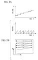
- Figs. 2A to 2C show driving patterns of acousto-optic devices in the optical stimulation apparatus in Fig. 1 and a light scanning pattern on a specimen.
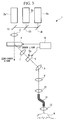
- Fig. 3 is a schematic diagram of a modification of the optical stimulation apparatus in Fig. 1.
- Fig. 4 is a schematic diagram of an optical-scanning examination apparatus according to an embodiment of the present invention.
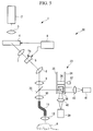
- Fig. 5 is a schematic diagram of a modification of the optical-scanning examination apparatus in Fig. 3.
- the optical stimulation apparatus 1 of this embodiment includes a laser light source 2 that emits laser light; a beam expander 3 that expands the laser beam; a first acousto-optic device (AOD) 4; a second acousto-optic device 5; an AOD control apparatus 6 that controls the acousto-optic devices 4 and 5; a telescope lens 7 that maintains the beam emitted from the first acousto-optic device 4 at a specific beam diameter; a pupil-projection lens 8 that forms an intermediate image of the light emitted from the second acousto-optic device 5; an imaging lens 9 that focuses the light forming the intermediate image by the pupil-projection lens 8; a first objective lens 10 that images the light focused by the imaging lens 9; an optical fiber bundle 11 of which one end is disposed at the image position of the first objective lens 10; and a second objective lens 12 disposed at the other end of the optical fiber bundle 11.
- the second objective lens 12 images the light carried by the optical
- a piezo transducer included in the first acousto-optic device 4
- high-frequency vibrations are applied to a crystal (for example, lead molybdate) via the piezo transducer, to vary the diffraction angle of light transmitted through the crystal in a single direction, for example, a direction parallel to the plane of the drawing in Fig. 1.
- Zero-order light which is transmitted straight through with respect to the incident light, is also emitted from the first acousto-optic device 4; in this embodiment, however, the zero-order light is not used, but the +1 order light adjacent thereto is used.
- the second acousto-optic device 5 also varies the diffraction angle of the light in one direction according to the high-frequency vibrations that the piezo transducer generates; however, it is disposed so as to vary the diffraction angle in a direction intersecting the direction in which the diffraction angle is varied by the first acousto-optic device 4, for example, in a direction orthogonal thereto. Similar to the first acousto-optic device 4, the second acousto-optic device 5 is configured so as to use the +1 order light and not the zero-order light in this embodiment.
- the AOD control apparatus 6 two-dimensionally scans the laser light from the laser light source 2 onto the specimen A, voltage signals that vary with a fixed period are supplied to the first and second acousto-optic devices 4 and 5, respectively.
- a voltage signal input to one device, the acousto-optic device 4 (5), is fixed, and the voltage signal to the other device, the acousto-optic device 5 (4), is varied at the fixed period.
- the voltage signals input to both acousto-optic devices 4 and 5 are fixed.
- the second acousto-optic device 5 Since the zero-order beam produced by the first acousto-optic device 4 is not used, the second acousto-optic device 5 is disposed at a position such that the +1-order beam passes through an aperture section 5a at the incident side thereof, without letting the zero-order beam pass therethrough. Also, the aperture section 5a has a diameter that allows the first-order beam over the entire range of diffraction angles modulated in response to the vibration frequencies generated by the piezo transducer to be incident on the second acousto-optic device 5.
- optical stimulation apparatus 1 of this embodiment having such a configuration, will be described below.
- the beam diameter of the laser light emitted from the laser light source 2 is expanded by the beam expander 3 and is incident on the first acousto-optic device 4.
- a +1 order beam is emitted at a diffraction angle according to the voltage signal input from the AOD control apparatus 6, is collimated by the telescope lens 7, and is incident on the second acousto-optic device 5.
- the +1 order beam from the first acousto-optic device 4 is input and a +1 order beam is emitted therefrom at a diffraction angle according to a voltage signal input from the AOD control apparatus 6.
- the light emitted from the second acousto-optic device 5 passes through the pupil projection lens 8, the imaging lens 9, and the objective lens 10 to be imaged onto one end of the optical fiber bundle 11, and propagates through the optical fiber bundle 11.
- the light is then re-imaged onto the specimen A by the second objective lens 12 disposed at the other end of the optical fiber bundle 11.
- the specimen A is irradiated with light from the laser light source 2, which allows an optical stimulus to be applied thereto.
- the second objective lens 12 for the specimen A is disposed at the end of the optical fiber bundle 11, the position and orientation of the second objective lens 12 can be freely adjusted by bending the optical fiber bundle 11. Therefore, the second objective lens 12 can be placed at a suitable position according to the shape of the specimen A and the location of the optical stimulus, which allows the optical stimulus to be accurately applied to a desired location.
- the diffraction direction of the first acousto-optic device 4 that is, the direction in which the diffraction angle of the +1 order beam emitted from the first acousto-optic device 4 is varied, and the diffraction direction of the second acousto-optic device 5 are arranged so as to be mutually orthogonal, the light emitted from the second acousto-optic device 5 can cover a wide two-dimensional region. Therefore, when setting the voltage signal input from the AOD control apparatus 6 to a specific value, the frequency of the high-frequency vibrations generated in response thereto is also set to a fixed value. As a result, the optical stimulus position of light irradiating the specimen A can be kept fixed at a specific position.
- varying the voltage signals input to both acousto-optic devices 4 and 5 from the AOD control apparatus 6 it is possible to move the optical stimulus position two-dimensionally.
- Fig. 2A to Fig. 2C by varying the voltage signal input to the first acousto-optic device 4 in a step-wise manner (Fig. 2A) and by varying the voltage signal input to the second acousto-optic device 5 in a triangular waveform (Fig. 2B), it is possible to two-dimensionally scan the optical stimulus position on the specimen A, as shown in Fig. 2C.
- the optical stimulation apparatus 1 by varying the vibration frequency, it is possible to change the diffraction angle at high speed, thus moving the optical stimulus position at high speed. Therefore, using the system in applications such as a case where the optical stimulus position is moved at high speed and an electrical signal obtained from the specimen is observed enables examination to be carried out more effectively. Also, with the acousto-optic devices 4 and 5, detectors are not needed, unlike the case where galvano mirrors are used, which affords an advantage in that the scanning speed is not limited by detector sensitivity and, furthermore, it is possible to make the apparatus more compact.
- the optical stimulation apparatus 1 In the optical stimulation apparatus 1 according to this embodiment, a description has been given of a case where a single laser light source 2 is used. However, instead of this, as shown in Fig. 3, a plurality of laser light sources 2a to 2c with different wavelengths may be used. In this case, the optical axes of the light beams from the laser light sources 2a to 2c may be combined by dichroic mirrors 13 and a mirror 14.
- the optical-scanning examination apparatus 20 includes the optical stimulation apparatus 1 shown in Fig. 1, an illumination optical system 21, and an examination optical system 22.
- the illumination optical system 21 includes, for example, a halogen lamp 23 that emits near-infrared light serving as excitation light, a collimator lens for converting the light from the halogen lamp 23 into a collimated beam, adjacent galvano mirrors 25 that two-dimensionally scan the collimated beam of light emitted from the collimator lens 24, and a half-mirror (optical-axis combining unit) 26 that combines the light scanned by the adjacent galvano mirrors 25 with the optical axis between the imaging lens 9 and the objective lens 10 of the optical stimulation apparatus 1.
- a halogen lamp 23 that emits near-infrared light serving as excitation light
- a collimator lens for converting the light from the halogen lamp 23 into a collimated beam
- adjacent galvano mirrors 25 that two-dimensionally scan the collimated beam of light
- the examination optical system 22 includes a dichroic mirror 27 that splits off fluorescence returning from the specimen A from the optical axis between the half-mirror 25 and the collimator lens 24; a barrier filter 28 that transmits fluorescence while cutting excitation light and light used as an optical stimulus; a dichroic mirror 29 that splits returning fluorescence passing through the barrier filter 28 into each wavelength; and two sets of fluorescence filters 30, focusing lenses 31, and photodetectors 32.
- the photodetectors 32 are photomultiplier tubes, for example.
- the near-infrared light emitted from the halogen lamp 23 is collimated by passing through the collimator lens 24, is two-dimensionally scanned by the adjacent galvano mirrors 25, and is made incident on the first objective lens 10 by the half-mirror 26.
- the light imaged onto the end surface of the optical fiber bundle 11 by the first objective lens 10 propagates through the optical fiber bundle 11 and is re-imaged onto the specimen A by the second objective lens 12.
- the examination site irradiated with near-infrared light on the specimen A then generates fluorescence.
- the generated fluorescence returns via the second objective lens 12, the optical fiber bundle 11, and the first objective lens 10, and is returned to the illumination optical system 21 by the half-mirror 26.
- the fluorescence then passes through the adjacent galvano mirrors 25, is split off from the illumination optical system 21 by the dichroic mirror 27, passes through the barrier filter 28 to reach the dichroic mirror 29, passes through the fluorescence filters 30 and the focusing lenses 31, and is detected by the photodetectors 32.
- the optical stimulation apparatus 1 By operating the optical stimulation apparatus 1 while performing examination of the fluorescence generated in the specimen A with the illumination optical system 21 and the examination optical system 22, it is possible to examine the response of the specimen A when performing optical stimulation of a specific position while moving the stimulus position at high speed, by means of the images acquired by the examination optical system 22.
- the light from the light source 23 is two-dimensionally scanned by the adjacent galvano mirrors 25.
- a disk-scanning-type scanning unit 33 may be provided.
- a focusing disk 34 and a pinhole disk 35 are connected via a drum 36, and the scanning unit 33 is rotated in one direction by means of a motor 37.
- the focusing disk 34 has a plurality of Fresnel lenses formed on one side of a glass substrate, and these Fresnel lenses are arranged so as to be staggered by a predetermined distance in the radial direction.
- the pinhole disk 35 has a plurality of pinholes in a substrate, and these pinholes are also arranged so as to be staggered by a predetermined distance in the radial direction.
- a dichroic mirror 38 is disposed between the focusing disk 34 and the pinhole disk 35. Fluorescence returning via the first objective lens 10, the half-mirror 26, and the pinhole disk 35 is reflected by the dichroic mirror 38 and is detected by a photodetector 39.
- reference numeral 40 represents a focusing lens
- reference numeral 41 represents a light source
- reference numeral 42 represents a collimator lens.
- the light from the light source 41 can pass through the plurality of pinholes simultaneously, thus allowing the specimen A to be scanned with a plurality of light spots, and it is therefore possible to acquire fluorescence images of the specimen A at high speed.
Abstract
Description
Claims (5)
- An optical stimulation apparatus comprising:wherein the scanning unit includes an acousto-optic device for varying a diffraction angle in response to a vibration frequency input thereto.a light source;a scanning unit that scans light from the light source; andan objective optical system that images the light scanned by the scanning unit onto a specimen;
- An optical stimulation apparatus according to Claim 1, wherein the scanning unit includes a first acousto-optic device for varying the diffraction angle in one direction in response to a vibration frequency input thereto, and a second acousto-optic device that diffracts the light from the first acousto-optic device in a direction crossing the diffraction direction of the first acousto-optic device.
- An optical-scanning examination apparatus comprising:wherein the second scanning unit includes an acousto-optic device that varies the diffraction angle in response to a vibration frequency input thereto.a first light source;a first scanning unit that scans light from the first light source;an objective optical system that images the light scanned by the first scanning unit onto a specimen;a photodetector that detects return light returning via the objective optical system and the first scanning unit;a second light source;a second scanning unit that scans light from the second light source; andan optical-axis combining unit that makes the optical axis of the light scanned by the second scanning unit coincident with the optical axis of the light from the first light source;
- An optical-scanning examination apparatus according to Claim 3, wherein the second scanning unit includes:a first acousto-optic device that varies the diffraction angle in one direction in response to a vibration frequency input thereto; anda second acousto-optic device that diffracts the light from the first acousto-optic device in a direction crossing the diffraction direction of the first acousto-optic device.
- An optical-scanning examination apparatus according to Claim 3, wherein the first scanning unit is a disk-type scanning unit in which a focusing disk and a pinhole disk are rotated.
Applications Claiming Priority (2)
| Application Number | Priority Date | Filing Date | Title |
|---|---|---|---|
| JP2004143579A JP4885429B2 (en) | 2004-05-13 | 2004-05-13 | Optical stimulator and optical scanning observation device |
| JP2004143579 | 2004-05-13 |
Publications (2)
| Publication Number | Publication Date |
|---|---|
| EP1596238A2 true EP1596238A2 (en) | 2005-11-16 |
| EP1596238A3 EP1596238A3 (en) | 2006-10-18 |
Family
ID=34936046
Family Applications (1)
| Application Number | Title | Priority Date | Filing Date |
|---|---|---|---|
| EP05009608A Withdrawn EP1596238A3 (en) | 2004-05-13 | 2005-05-02 | Optical stimulation apparatus and optical-scanning examination apparatus |
Country Status (3)
| Country | Link |
|---|---|
| US (1) | US20050253056A1 (en) |
| EP (1) | EP1596238A3 (en) |
| JP (1) | JP4885429B2 (en) |
Cited By (3)
| Publication number | Priority date | Publication date | Assignee | Title |
|---|---|---|---|---|
| EP1830215A1 (en) * | 2006-03-03 | 2007-09-05 | Olympus Corporation | Laser scanning microscope |
| EP1855139A1 (en) * | 2006-05-12 | 2007-11-14 | Fujinon Corporation | Confocal image signal obtaining method and apparatus, and sampling operation state obtaining apparatus |
| DE102007039988A1 (en) | 2007-08-23 | 2009-03-12 | Leica Microsystems Cms Gmbh | Optical arrangement and a microscope |
Families Citing this family (10)
| Publication number | Priority date | Publication date | Assignee | Title |
|---|---|---|---|---|
| ITMI20051609A1 (en) * | 2005-08-29 | 2007-02-28 | Laservall Spa | SOLID STATE LASER SOURCE LATERALLY PUMPED AND PUMPING PROCEDURE OF A SOLID STATE LASER SOURCE |
| JP4887989B2 (en) * | 2005-12-02 | 2012-02-29 | ナノフォトン株式会社 | Optical microscope and spectrum measuring method |
| JP2007298658A (en) * | 2006-04-28 | 2007-11-15 | Olympus Corp | Confocal microscope |
| JP5133600B2 (en) * | 2006-05-29 | 2013-01-30 | オリンパス株式会社 | Laser scanning microscope and microscope observation method |
| KR100791005B1 (en) | 2006-12-01 | 2008-01-04 | 삼성전자주식회사 | Equipment and method for transmittance measurement of photomask under off axis illumination |
| GB0721343D0 (en) * | 2007-10-30 | 2007-12-19 | Perkinelmer Ltd | Improvements in and relating to scanning confocal microscopy |
| CN102215736B (en) | 2008-11-18 | 2015-04-29 | 斯特赖克公司 | Endoscopic led light source having a feedback control system |
| JP6442788B2 (en) | 2013-03-06 | 2018-12-26 | インサイテック・リミテッド | Frequency optimization in ultrasonic treatment |
| US10687697B2 (en) | 2013-03-15 | 2020-06-23 | Stryker Corporation | Endoscopic light source and imaging system |
| US10690904B2 (en) | 2016-04-12 | 2020-06-23 | Stryker Corporation | Multiple imaging modality light source |
Citations (6)
| Publication number | Priority date | Publication date | Assignee | Title |
|---|---|---|---|---|
| US4827125A (en) * | 1987-04-29 | 1989-05-02 | The United States Of America As Represented By The Secretary Of The Department Of Health And Human Services | Confocal scanning laser microscope having no moving parts |
| US4893008A (en) * | 1987-06-09 | 1990-01-09 | Olympus Optical Co., Ltd. | Scanning optical microscope |
| US6094300A (en) * | 1996-11-21 | 2000-07-25 | Olympus Optical Co., Ltd. | Laser scanning microscope |
| US20020141051A1 (en) * | 2001-03-27 | 2002-10-03 | Vogt William I. | Single and multi-aperture, translationally-coupled confocal microscope |
| US20020176076A1 (en) * | 1999-07-28 | 2002-11-28 | Ahmed Bouzid | Laser scanning fluorescence microscopy with compensation for spatial dispersion of fast laser pulses |
| EP1359452A1 (en) * | 2002-05-03 | 2003-11-05 | Max-Planck-Gesellschaft zur Förderung der Wissenschaften e.V. | Confocal microscope having two micro-lens arrays and a pinhole array |
Family Cites Families (18)
| Publication number | Priority date | Publication date | Assignee | Title |
|---|---|---|---|---|
| US141051A (en) * | 1873-07-22 | Improvement in hoisting-machines | ||
| US176076A (en) * | 1876-04-11 | Improvement in neck-yokes | ||
| JPH0718975B2 (en) * | 1986-06-20 | 1995-03-06 | オリンパス光学工業株式会社 | Scanning optical microscope |
| JP3343276B2 (en) * | 1993-04-15 | 2002-11-11 | 興和株式会社 | Laser scanning optical microscope |
| US5822486A (en) * | 1995-11-02 | 1998-10-13 | General Scanning, Inc. | Scanned remote imaging method and system and method of determining optimum design characteristics of a filter for use therein |
| US5796511A (en) * | 1996-08-30 | 1998-08-18 | Agfa Division, Bayer Corporation | Multi-beam scanner with acousto-optic element for scanning imaging surfaces |
| JP3930929B2 (en) * | 1996-11-28 | 2007-06-13 | オリンパス株式会社 | Confocal microscope |
| JPH11218682A (en) * | 1998-01-30 | 1999-08-10 | Fujitsu Ltd | Laser scanning microscope |
| DE19827139C2 (en) * | 1998-06-18 | 2002-01-31 | Zeiss Carl Jena Gmbh | Microscope with a short-pulse laser coupled in via an optical fiber |
| US6747795B2 (en) * | 2000-06-30 | 2004-06-08 | The General Hospital Corporation | Fiber-coupled multiplexed confocal microscope |
| JP2002098901A (en) * | 2000-09-22 | 2002-04-05 | Olympus Optical Co Ltd | Scanning laser microscope |
| DE10050529B4 (en) * | 2000-10-11 | 2016-06-09 | Leica Microsystems Cms Gmbh | Method for beam control in a scanning microscope, arrangement for beam control in a scanning microscope and scanning microscope |
| US7196843B2 (en) * | 2002-03-27 | 2007-03-27 | Olympus Optical Co., Ltd. | Confocal microscope apparatus |
| JP4136440B2 (en) * | 2002-04-26 | 2008-08-20 | オリンパス株式会社 | Microscope equipment |
| JP2003344777A (en) * | 2002-05-24 | 2003-12-03 | Japan Science & Technology Corp | Optical fiber microscope and endoscope |
| DE10302259B3 (en) * | 2003-01-22 | 2004-06-03 | Leica Microsystems Heidelberg Gmbh | Confocal scanning microscope has acousto-optical component for directing partial beam obtained from illumination beam onto monitoring detector for illumination intensity regulation |
| JP2004317437A (en) * | 2003-04-18 | 2004-11-11 | Olympus Corp | Optical imaging apparatus |
| DE102004034974A1 (en) * | 2004-07-16 | 2006-02-16 | Carl Zeiss Jena Gmbh | Method for the image capture of objects by means of a light-scanning microscope with point-shaped light source distribution |
-
2004
- 2004-05-13 JP JP2004143579A patent/JP4885429B2/en not_active Expired - Fee Related
-
2005
- 2005-05-02 EP EP05009608A patent/EP1596238A3/en not_active Withdrawn
- 2005-05-02 US US11/118,411 patent/US20050253056A1/en not_active Abandoned
Patent Citations (6)
| Publication number | Priority date | Publication date | Assignee | Title |
|---|---|---|---|---|
| US4827125A (en) * | 1987-04-29 | 1989-05-02 | The United States Of America As Represented By The Secretary Of The Department Of Health And Human Services | Confocal scanning laser microscope having no moving parts |
| US4893008A (en) * | 1987-06-09 | 1990-01-09 | Olympus Optical Co., Ltd. | Scanning optical microscope |
| US6094300A (en) * | 1996-11-21 | 2000-07-25 | Olympus Optical Co., Ltd. | Laser scanning microscope |
| US20020176076A1 (en) * | 1999-07-28 | 2002-11-28 | Ahmed Bouzid | Laser scanning fluorescence microscopy with compensation for spatial dispersion of fast laser pulses |
| US20020141051A1 (en) * | 2001-03-27 | 2002-10-03 | Vogt William I. | Single and multi-aperture, translationally-coupled confocal microscope |
| EP1359452A1 (en) * | 2002-05-03 | 2003-11-05 | Max-Planck-Gesellschaft zur Förderung der Wissenschaften e.V. | Confocal microscope having two micro-lens arrays and a pinhole array |
Cited By (5)
| Publication number | Priority date | Publication date | Assignee | Title |
|---|---|---|---|---|
| EP1830215A1 (en) * | 2006-03-03 | 2007-09-05 | Olympus Corporation | Laser scanning microscope |
| US7485876B2 (en) | 2006-03-03 | 2009-02-03 | Olympus Corporation | Laser scanning microscope |
| EP1855139A1 (en) * | 2006-05-12 | 2007-11-14 | Fujinon Corporation | Confocal image signal obtaining method and apparatus, and sampling operation state obtaining apparatus |
| DE102007039988A1 (en) | 2007-08-23 | 2009-03-12 | Leica Microsystems Cms Gmbh | Optical arrangement and a microscope |
| DE102007039988B4 (en) | 2007-08-23 | 2018-03-15 | Leica Microsystems Cms Gmbh | microscope |
Also Published As
| Publication number | Publication date |
|---|---|
| JP4885429B2 (en) | 2012-02-29 |
| JP2005326549A (en) | 2005-11-24 |
| US20050253056A1 (en) | 2005-11-17 |
| EP1596238A3 (en) | 2006-10-18 |
Similar Documents
| Publication | Publication Date | Title |
|---|---|---|
| EP1596238A2 (en) | Optical stimulation apparatus and optical-scanning examination apparatus | |
| US7400446B2 (en) | Confocal microscope | |
| EP1580586B1 (en) | Scanning confocal microscope | |
| US8773760B2 (en) | Multi-point scan architecture | |
| US7561265B2 (en) | Optical microscope and spectrum measuring method | |
| JP5259154B2 (en) | Scanning laser microscope | |
| WO2018147165A1 (en) | Spectroscopic microscope, and spectroscopic observation method | |
| US20070051869A1 (en) | Scanning microscope and method for examining a sample by using scanning microscopy | |
| US20170261731A1 (en) | Light-field microscope | |
| US20130120563A1 (en) | Image generation device | |
| US7838818B2 (en) | Light-stimulus illumination apparatus which scans light-stimulus laser light in a direction intersecting an optical axis | |
| JP2007506955A (en) | Scanning microscope with evanescent wave illumination | |
| JP4820759B2 (en) | Scanning microscope | |
| JP5589374B2 (en) | Microscope equipment | |
| JP6210754B2 (en) | Scanning optical microscope | |
| JPH11133306A (en) | Confocal microscope | |
| US20020085274A1 (en) | Laser microscope | |
| JP2006322767A (en) | Optical tomographic imaging system | |
| US20210033838A1 (en) | Apparatuses and methods for multi-direction digital scanned light sheet microscopy | |
| JP2001506015A (en) | Scanning microscope that optically excites samples at multiple sample locations simultaneously | |
| JP4386462B2 (en) | Confocal microscope for optical measurement of the observed volume | |
| JP4885685B2 (en) | Optical device and microscope | |
| KR100519266B1 (en) | Confocal microscope | |
| JP2006510932A (en) | Coherence microscope | |
| JP2006003747A (en) | Optical scanning type observation apparatus |
Legal Events
| Date | Code | Title | Description |
|---|---|---|---|
| PUAI | Public reference made under article 153(3) epc to a published international application that has entered the european phase |
Free format text: ORIGINAL CODE: 0009012 |
|
| AK | Designated contracting states |
Kind code of ref document: A2 Designated state(s): AT BE BG CH CY CZ DE DK EE ES FI FR GB GR HU IE IS IT LI LT LU MC NL PL PT RO SE SI SK TR |
|
| AX | Request for extension of the european patent |
Extension state: AL BA HR LV MK YU |
|
| PUAL | Search report despatched |
Free format text: ORIGINAL CODE: 0009013 |
|
| AK | Designated contracting states |
Kind code of ref document: A3 Designated state(s): AT BE BG CH CY CZ DE DK EE ES FI FR GB GR HU IE IS IT LI LT LU MC NL PL PT RO SE SI SK TR |
|
| AX | Request for extension of the european patent |
Extension state: AL BA HR LV MK YU |
|
| RIC1 | Information provided on ipc code assigned before grant |
Ipc: G02B 21/00 20060101ALI20060912BHEP Ipc: G02B 21/16 20060101AFI20060912BHEP |
|
| 17P | Request for examination filed |
Effective date: 20061120 |
|
| AKX | Designation fees paid |
Designated state(s): DE FR GB |
|
| 17Q | First examination report despatched |
Effective date: 20071109 |
|
| STAA | Information on the status of an ep patent application or granted ep patent |
Free format text: STATUS: THE APPLICATION IS DEEMED TO BE WITHDRAWN |
|
| 18D | Application deemed to be withdrawn |
Effective date: 20080320 |