EP1598025A2 - Electrosurgical device for cell necrosis induction - Google Patents
Electrosurgical device for cell necrosis induction Download PDFInfo
- Publication number
- EP1598025A2 EP1598025A2 EP05075334A EP05075334A EP1598025A2 EP 1598025 A2 EP1598025 A2 EP 1598025A2 EP 05075334 A EP05075334 A EP 05075334A EP 05075334 A EP05075334 A EP 05075334A EP 1598025 A2 EP1598025 A2 EP 1598025A2
- Authority
- EP
- European Patent Office
- Prior art keywords
- electrodes
- electrode
- introducer
- deployable
- energy source
- Prior art date
- Legal status (The legal status is an assumption and is not a legal conclusion. Google has not performed a legal analysis and makes no representation as to the accuracy of the status listed.)
- Withdrawn
Links
- NTPUYCSUXJYCMS-UHFFFAOYSA-N C=CCCCCC(CC1)CC1=C Chemical compound C=CCCCCC(CC1)CC1=C NTPUYCSUXJYCMS-UHFFFAOYSA-N 0.000 description 1
Images


Classifications
-
- A—HUMAN NECESSITIES
- A61—MEDICAL OR VETERINARY SCIENCE; HYGIENE
- A61B—DIAGNOSIS; SURGERY; IDENTIFICATION
- A61B18/00—Surgical instruments, devices or methods for transferring non-mechanical forms of energy to or from the body
- A61B18/04—Surgical instruments, devices or methods for transferring non-mechanical forms of energy to or from the body by heating
- A61B18/12—Surgical instruments, devices or methods for transferring non-mechanical forms of energy to or from the body by heating by passing a current through the tissue to be heated, e.g. high-frequency current
- A61B18/14—Probes or electrodes therefor
- A61B18/1482—Probes or electrodes therefor having a long rigid shaft for accessing the inner body transcutaneously in minimal invasive surgery, e.g. laparoscopy
-
- A—HUMAN NECESSITIES
- A61—MEDICAL OR VETERINARY SCIENCE; HYGIENE
- A61B—DIAGNOSIS; SURGERY; IDENTIFICATION
- A61B18/00—Surgical instruments, devices or methods for transferring non-mechanical forms of energy to or from the body
- A61B18/04—Surgical instruments, devices or methods for transferring non-mechanical forms of energy to or from the body by heating
- A61B18/12—Surgical instruments, devices or methods for transferring non-mechanical forms of energy to or from the body by heating by passing a current through the tissue to be heated, e.g. high-frequency current
- A61B18/14—Probes or electrodes therefor
- A61B18/1477—Needle-like probes
-
- A—HUMAN NECESSITIES
- A61—MEDICAL OR VETERINARY SCIENCE; HYGIENE
- A61B—DIAGNOSIS; SURGERY; IDENTIFICATION
- A61B18/00—Surgical instruments, devices or methods for transferring non-mechanical forms of energy to or from the body
- A61B18/04—Surgical instruments, devices or methods for transferring non-mechanical forms of energy to or from the body by heating
- A61B18/12—Surgical instruments, devices or methods for transferring non-mechanical forms of energy to or from the body by heating by passing a current through the tissue to be heated, e.g. high-frequency current
- A61B18/14—Probes or electrodes therefor
- A61B18/148—Probes or electrodes therefor having a short, rigid shaft for accessing the inner body transcutaneously, e.g. for neurosurgery or arthroscopy
-
- A—HUMAN NECESSITIES
- A61—MEDICAL OR VETERINARY SCIENCE; HYGIENE
- A61B—DIAGNOSIS; SURGERY; IDENTIFICATION
- A61B18/00—Surgical instruments, devices or methods for transferring non-mechanical forms of energy to or from the body
- A61B18/18—Surgical instruments, devices or methods for transferring non-mechanical forms of energy to or from the body by applying electromagnetic radiation, e.g. microwaves
- A61B18/1815—Surgical instruments, devices or methods for transferring non-mechanical forms of energy to or from the body by applying electromagnetic radiation, e.g. microwaves using microwaves
-
- A—HUMAN NECESSITIES
- A61—MEDICAL OR VETERINARY SCIENCE; HYGIENE
- A61N—ELECTROTHERAPY; MAGNETOTHERAPY; RADIATION THERAPY; ULTRASOUND THERAPY
- A61N1/00—Electrotherapy; Circuits therefor
- A61N1/02—Details
- A61N1/04—Electrodes
- A61N1/06—Electrodes for high-frequency therapy
-
- A—HUMAN NECESSITIES
- A61—MEDICAL OR VETERINARY SCIENCE; HYGIENE
- A61N—ELECTROTHERAPY; MAGNETOTHERAPY; RADIATION THERAPY; ULTRASOUND THERAPY
- A61N1/00—Electrotherapy; Circuits therefor
- A61N1/40—Applying electric fields by inductive or capacitive coupling ; Applying radio-frequency signals
- A61N1/403—Applying electric fields by inductive or capacitive coupling ; Applying radio-frequency signals for thermotherapy, e.g. hyperthermia
-
- A—HUMAN NECESSITIES
- A61—MEDICAL OR VETERINARY SCIENCE; HYGIENE
- A61B—DIAGNOSIS; SURGERY; IDENTIFICATION
- A61B18/00—Surgical instruments, devices or methods for transferring non-mechanical forms of energy to or from the body
- A61B18/04—Surgical instruments, devices or methods for transferring non-mechanical forms of energy to or from the body by heating
- A61B18/12—Surgical instruments, devices or methods for transferring non-mechanical forms of energy to or from the body by heating by passing a current through the tissue to be heated, e.g. high-frequency current
- A61B18/14—Probes or electrodes therefor
- A61B18/1402—Probes for open surgery
-
- A—HUMAN NECESSITIES
- A61—MEDICAL OR VETERINARY SCIENCE; HYGIENE
- A61B—DIAGNOSIS; SURGERY; IDENTIFICATION
- A61B18/00—Surgical instruments, devices or methods for transferring non-mechanical forms of energy to or from the body
- A61B18/04—Surgical instruments, devices or methods for transferring non-mechanical forms of energy to or from the body by heating
- A61B18/12—Surgical instruments, devices or methods for transferring non-mechanical forms of energy to or from the body by heating by passing a current through the tissue to be heated, e.g. high-frequency current
- A61B18/14—Probes or electrodes therefor
- A61B18/1485—Probes or electrodes therefor having a short rigid shaft for accessing the inner body through natural openings
-
- A—HUMAN NECESSITIES
- A61—MEDICAL OR VETERINARY SCIENCE; HYGIENE
- A61B—DIAGNOSIS; SURGERY; IDENTIFICATION
- A61B18/00—Surgical instruments, devices or methods for transferring non-mechanical forms of energy to or from the body
- A61B18/04—Surgical instruments, devices or methods for transferring non-mechanical forms of energy to or from the body by heating
- A61B18/12—Surgical instruments, devices or methods for transferring non-mechanical forms of energy to or from the body by heating by passing a current through the tissue to be heated, e.g. high-frequency current
- A61B18/14—Probes or electrodes therefor
- A61B18/1492—Probes or electrodes therefor having a flexible, catheter-like structure, e.g. for heart ablation
-
- A—HUMAN NECESSITIES
- A61—MEDICAL OR VETERINARY SCIENCE; HYGIENE
- A61B—DIAGNOSIS; SURGERY; IDENTIFICATION
- A61B17/00—Surgical instruments, devices or methods, e.g. tourniquets
- A61B2017/00017—Electrical control of surgical instruments
- A61B2017/00022—Sensing or detecting at the treatment site
- A61B2017/00084—Temperature
- A61B2017/00101—Temperature using an array of thermosensors
-
- A—HUMAN NECESSITIES
- A61—MEDICAL OR VETERINARY SCIENCE; HYGIENE
- A61B—DIAGNOSIS; SURGERY; IDENTIFICATION
- A61B18/00—Surgical instruments, devices or methods for transferring non-mechanical forms of energy to or from the body
- A61B2018/00005—Cooling or heating of the probe or tissue immediately surrounding the probe
- A61B2018/00011—Cooling or heating of the probe or tissue immediately surrounding the probe with fluids
- A61B2018/00023—Cooling or heating of the probe or tissue immediately surrounding the probe with fluids closed, i.e. without wound contact by the fluid
-
- A—HUMAN NECESSITIES
- A61—MEDICAL OR VETERINARY SCIENCE; HYGIENE
- A61B—DIAGNOSIS; SURGERY; IDENTIFICATION
- A61B18/00—Surgical instruments, devices or methods for transferring non-mechanical forms of energy to or from the body
- A61B2018/00053—Mechanical features of the instrument of device
- A61B2018/00059—Material properties
- A61B2018/00071—Electrical conductivity
- A61B2018/00083—Electrical conductivity low, i.e. electrically insulating
-
- A—HUMAN NECESSITIES
- A61—MEDICAL OR VETERINARY SCIENCE; HYGIENE
- A61B—DIAGNOSIS; SURGERY; IDENTIFICATION
- A61B18/00—Surgical instruments, devices or methods for transferring non-mechanical forms of energy to or from the body
- A61B2018/00053—Mechanical features of the instrument of device
- A61B2018/00184—Moving parts
- A61B2018/00196—Moving parts reciprocating lengthwise
-
- A—HUMAN NECESSITIES
- A61—MEDICAL OR VETERINARY SCIENCE; HYGIENE
- A61B—DIAGNOSIS; SURGERY; IDENTIFICATION
- A61B18/00—Surgical instruments, devices or methods for transferring non-mechanical forms of energy to or from the body
- A61B2018/00053—Mechanical features of the instrument of device
- A61B2018/00273—Anchoring means for temporary attachment of a device to tissue
-
- A—HUMAN NECESSITIES
- A61—MEDICAL OR VETERINARY SCIENCE; HYGIENE
- A61B—DIAGNOSIS; SURGERY; IDENTIFICATION
- A61B18/00—Surgical instruments, devices or methods for transferring non-mechanical forms of energy to or from the body
- A61B2018/00315—Surgical instruments, devices or methods for transferring non-mechanical forms of energy to or from the body for treatment of particular body parts
- A61B2018/00452—Skin
- A61B2018/00476—Hair follicles
-
- A—HUMAN NECESSITIES
- A61—MEDICAL OR VETERINARY SCIENCE; HYGIENE
- A61B—DIAGNOSIS; SURGERY; IDENTIFICATION
- A61B18/00—Surgical instruments, devices or methods for transferring non-mechanical forms of energy to or from the body
- A61B2018/00571—Surgical instruments, devices or methods for transferring non-mechanical forms of energy to or from the body for achieving a particular surgical effect
- A61B2018/00577—Ablation
-
- A—HUMAN NECESSITIES
- A61—MEDICAL OR VETERINARY SCIENCE; HYGIENE
- A61B—DIAGNOSIS; SURGERY; IDENTIFICATION
- A61B18/00—Surgical instruments, devices or methods for transferring non-mechanical forms of energy to or from the body
- A61B2018/00636—Sensing and controlling the application of energy
- A61B2018/00642—Sensing and controlling the application of energy with feedback, i.e. closed loop control
- A61B2018/00654—Sensing and controlling the application of energy with feedback, i.e. closed loop control with individual control of each of a plurality of energy emitting elements
-
- A—HUMAN NECESSITIES
- A61—MEDICAL OR VETERINARY SCIENCE; HYGIENE
- A61B—DIAGNOSIS; SURGERY; IDENTIFICATION
- A61B18/00—Surgical instruments, devices or methods for transferring non-mechanical forms of energy to or from the body
- A61B2018/00636—Sensing and controlling the application of energy
- A61B2018/00666—Sensing and controlling the application of energy using a threshold value
- A61B2018/00678—Sensing and controlling the application of energy using a threshold value upper
-
- A—HUMAN NECESSITIES
- A61—MEDICAL OR VETERINARY SCIENCE; HYGIENE
- A61B—DIAGNOSIS; SURGERY; IDENTIFICATION
- A61B18/00—Surgical instruments, devices or methods for transferring non-mechanical forms of energy to or from the body
- A61B2018/00636—Sensing and controlling the application of energy
- A61B2018/00696—Controlled or regulated parameters
- A61B2018/00702—Power or energy
- A61B2018/00708—Power or energy switching the power on or off
-
- A—HUMAN NECESSITIES
- A61—MEDICAL OR VETERINARY SCIENCE; HYGIENE
- A61B—DIAGNOSIS; SURGERY; IDENTIFICATION
- A61B18/00—Surgical instruments, devices or methods for transferring non-mechanical forms of energy to or from the body
- A61B2018/00636—Sensing and controlling the application of energy
- A61B2018/00696—Controlled or regulated parameters
- A61B2018/00744—Fluid flow
-
- A—HUMAN NECESSITIES
- A61—MEDICAL OR VETERINARY SCIENCE; HYGIENE
- A61B—DIAGNOSIS; SURGERY; IDENTIFICATION
- A61B18/00—Surgical instruments, devices or methods for transferring non-mechanical forms of energy to or from the body
- A61B2018/00636—Sensing and controlling the application of energy
- A61B2018/00773—Sensed parameters
- A61B2018/00779—Power or energy
-
- A—HUMAN NECESSITIES
- A61—MEDICAL OR VETERINARY SCIENCE; HYGIENE
- A61B—DIAGNOSIS; SURGERY; IDENTIFICATION
- A61B18/00—Surgical instruments, devices or methods for transferring non-mechanical forms of energy to or from the body
- A61B2018/00636—Sensing and controlling the application of energy
- A61B2018/00773—Sensed parameters
- A61B2018/00791—Temperature
- A61B2018/00797—Temperature measured by multiple temperature sensors
-
- A—HUMAN NECESSITIES
- A61—MEDICAL OR VETERINARY SCIENCE; HYGIENE
- A61B—DIAGNOSIS; SURGERY; IDENTIFICATION
- A61B18/00—Surgical instruments, devices or methods for transferring non-mechanical forms of energy to or from the body
- A61B2018/00636—Sensing and controlling the application of energy
- A61B2018/00773—Sensed parameters
- A61B2018/00827—Current
-
- A—HUMAN NECESSITIES
- A61—MEDICAL OR VETERINARY SCIENCE; HYGIENE
- A61B—DIAGNOSIS; SURGERY; IDENTIFICATION
- A61B18/00—Surgical instruments, devices or methods for transferring non-mechanical forms of energy to or from the body
- A61B2018/00636—Sensing and controlling the application of energy
- A61B2018/00773—Sensed parameters
- A61B2018/00875—Resistance or impedance
-
- A—HUMAN NECESSITIES
- A61—MEDICAL OR VETERINARY SCIENCE; HYGIENE
- A61B—DIAGNOSIS; SURGERY; IDENTIFICATION
- A61B18/00—Surgical instruments, devices or methods for transferring non-mechanical forms of energy to or from the body
- A61B2018/00636—Sensing and controlling the application of energy
- A61B2018/00773—Sensed parameters
- A61B2018/00892—Voltage
-
- A—HUMAN NECESSITIES
- A61—MEDICAL OR VETERINARY SCIENCE; HYGIENE
- A61B—DIAGNOSIS; SURGERY; IDENTIFICATION
- A61B18/00—Surgical instruments, devices or methods for transferring non-mechanical forms of energy to or from the body
- A61B18/04—Surgical instruments, devices or methods for transferring non-mechanical forms of energy to or from the body by heating
- A61B18/12—Surgical instruments, devices or methods for transferring non-mechanical forms of energy to or from the body by heating by passing a current through the tissue to be heated, e.g. high-frequency current
- A61B18/1206—Generators therefor
- A61B2018/124—Generators therefor switching the output to different electrodes, e.g. sequentially
-
- A—HUMAN NECESSITIES
- A61—MEDICAL OR VETERINARY SCIENCE; HYGIENE
- A61B—DIAGNOSIS; SURGERY; IDENTIFICATION
- A61B18/00—Surgical instruments, devices or methods for transferring non-mechanical forms of energy to or from the body
- A61B18/04—Surgical instruments, devices or methods for transferring non-mechanical forms of energy to or from the body by heating
- A61B18/12—Surgical instruments, devices or methods for transferring non-mechanical forms of energy to or from the body by heating by passing a current through the tissue to be heated, e.g. high-frequency current
- A61B18/1206—Generators therefor
- A61B2018/1246—Generators therefor characterised by the output polarity
- A61B2018/1253—Generators therefor characterised by the output polarity monopolar
-
- A—HUMAN NECESSITIES
- A61—MEDICAL OR VETERINARY SCIENCE; HYGIENE
- A61B—DIAGNOSIS; SURGERY; IDENTIFICATION
- A61B18/00—Surgical instruments, devices or methods for transferring non-mechanical forms of energy to or from the body
- A61B18/04—Surgical instruments, devices or methods for transferring non-mechanical forms of energy to or from the body by heating
- A61B18/12—Surgical instruments, devices or methods for transferring non-mechanical forms of energy to or from the body by heating by passing a current through the tissue to be heated, e.g. high-frequency current
- A61B18/1206—Generators therefor
- A61B2018/1246—Generators therefor characterised by the output polarity
- A61B2018/126—Generators therefor characterised by the output polarity bipolar
-
- A—HUMAN NECESSITIES
- A61—MEDICAL OR VETERINARY SCIENCE; HYGIENE
- A61B—DIAGNOSIS; SURGERY; IDENTIFICATION
- A61B18/00—Surgical instruments, devices or methods for transferring non-mechanical forms of energy to or from the body
- A61B18/04—Surgical instruments, devices or methods for transferring non-mechanical forms of energy to or from the body by heating
- A61B18/12—Surgical instruments, devices or methods for transferring non-mechanical forms of energy to or from the body by heating by passing a current through the tissue to be heated, e.g. high-frequency current
- A61B18/14—Probes or electrodes therefor
- A61B2018/1405—Electrodes having a specific shape
- A61B2018/1425—Needle
- A61B2018/143—Needle multiple needles
-
- A—HUMAN NECESSITIES
- A61—MEDICAL OR VETERINARY SCIENCE; HYGIENE
- A61B—DIAGNOSIS; SURGERY; IDENTIFICATION
- A61B18/00—Surgical instruments, devices or methods for transferring non-mechanical forms of energy to or from the body
- A61B18/04—Surgical instruments, devices or methods for transferring non-mechanical forms of energy to or from the body by heating
- A61B18/12—Surgical instruments, devices or methods for transferring non-mechanical forms of energy to or from the body by heating by passing a current through the tissue to be heated, e.g. high-frequency current
- A61B18/14—Probes or electrodes therefor
- A61B2018/1405—Electrodes having a specific shape
- A61B2018/1425—Needle
- A61B2018/1432—Needle curved
-
- A—HUMAN NECESSITIES
- A61—MEDICAL OR VETERINARY SCIENCE; HYGIENE
- A61B—DIAGNOSIS; SURGERY; IDENTIFICATION
- A61B18/00—Surgical instruments, devices or methods for transferring non-mechanical forms of energy to or from the body
- A61B18/04—Surgical instruments, devices or methods for transferring non-mechanical forms of energy to or from the body by heating
- A61B18/12—Surgical instruments, devices or methods for transferring non-mechanical forms of energy to or from the body by heating by passing a current through the tissue to be heated, e.g. high-frequency current
- A61B18/14—Probes or electrodes therefor
- A61B2018/1405—Electrodes having a specific shape
- A61B2018/1435—Spiral
-
- A—HUMAN NECESSITIES
- A61—MEDICAL OR VETERINARY SCIENCE; HYGIENE
- A61B—DIAGNOSIS; SURGERY; IDENTIFICATION
- A61B18/00—Surgical instruments, devices or methods for transferring non-mechanical forms of energy to or from the body
- A61B18/04—Surgical instruments, devices or methods for transferring non-mechanical forms of energy to or from the body by heating
- A61B18/12—Surgical instruments, devices or methods for transferring non-mechanical forms of energy to or from the body by heating by passing a current through the tissue to be heated, e.g. high-frequency current
- A61B18/14—Probes or electrodes therefor
- A61B2018/1472—Probes or electrodes therefor for use with liquid electrolyte, e.g. virtual electrodes
-
- A—HUMAN NECESSITIES
- A61—MEDICAL OR VETERINARY SCIENCE; HYGIENE
- A61B—DIAGNOSIS; SURGERY; IDENTIFICATION
- A61B18/00—Surgical instruments, devices or methods for transferring non-mechanical forms of energy to or from the body
- A61B18/04—Surgical instruments, devices or methods for transferring non-mechanical forms of energy to or from the body by heating
- A61B18/12—Surgical instruments, devices or methods for transferring non-mechanical forms of energy to or from the body by heating by passing a current through the tissue to be heated, e.g. high-frequency current
- A61B18/14—Probes or electrodes therefor
- A61B2018/1475—Electrodes retractable in or deployable from a housing
-
- A—HUMAN NECESSITIES
- A61—MEDICAL OR VETERINARY SCIENCE; HYGIENE
- A61B—DIAGNOSIS; SURGERY; IDENTIFICATION
- A61B18/00—Surgical instruments, devices or methods for transferring non-mechanical forms of energy to or from the body
- A61B18/04—Surgical instruments, devices or methods for transferring non-mechanical forms of energy to or from the body by heating
- A61B18/12—Surgical instruments, devices or methods for transferring non-mechanical forms of energy to or from the body by heating by passing a current through the tissue to be heated, e.g. high-frequency current
- A61B18/14—Probes or electrodes therefor
- A61B18/16—Indifferent or passive electrodes for grounding
- A61B2018/162—Indifferent or passive electrodes for grounding located on the probe body
-
- A—HUMAN NECESSITIES
- A61—MEDICAL OR VETERINARY SCIENCE; HYGIENE
- A61B—DIAGNOSIS; SURGERY; IDENTIFICATION
- A61B2218/00—Details of surgical instruments, devices or methods for transferring non-mechanical forms of energy to or from the body
- A61B2218/001—Details of surgical instruments, devices or methods for transferring non-mechanical forms of energy to or from the body having means for irrigation and/or aspiration of substances to and/or from the surgical site
- A61B2218/002—Irrigation
-
- A—HUMAN NECESSITIES
- A61—MEDICAL OR VETERINARY SCIENCE; HYGIENE
- A61M—DEVICES FOR INTRODUCING MEDIA INTO, OR ONTO, THE BODY; DEVICES FOR TRANSDUCING BODY MEDIA OR FOR TAKING MEDIA FROM THE BODY; DEVICES FOR PRODUCING OR ENDING SLEEP OR STUPOR
- A61M25/00—Catheters; Hollow probes
- A61M25/0067—Catheters; Hollow probes characterised by the distal end, e.g. tips
- A61M25/0068—Static characteristics of the catheter tip, e.g. shape, atraumatic tip, curved tip or tip structure
- A61M25/007—Side holes, e.g. their profiles or arrangements; Provisions to keep side holes unblocked
-
- A—HUMAN NECESSITIES
- A61—MEDICAL OR VETERINARY SCIENCE; HYGIENE
- A61M—DEVICES FOR INTRODUCING MEDIA INTO, OR ONTO, THE BODY; DEVICES FOR TRANSDUCING BODY MEDIA OR FOR TAKING MEDIA FROM THE BODY; DEVICES FOR PRODUCING OR ENDING SLEEP OR STUPOR
- A61M3/00—Medical syringes, e.g. enemata; Irrigators
- A61M3/02—Enemata; Irrigators
- A61M3/0279—Cannula; Nozzles; Tips; their connection means
-
- A—HUMAN NECESSITIES
- A61—MEDICAL OR VETERINARY SCIENCE; HYGIENE
- A61N—ELECTROTHERAPY; MAGNETOTHERAPY; RADIATION THERAPY; ULTRASOUND THERAPY
- A61N5/00—Radiation therapy
- A61N5/02—Radiation therapy using microwaves
- A61N5/04—Radiators for near-field treatment
Definitions
- This invention relates generally to a cell necrosis apparatus, and more particularly to a cell necrosis apparatus with an introducer and deployable electrodes.
- hyperthermia As a tool for treatment of tumors. It is known that elevating the temperature of tumors is helpful in the treatment and management of cancerous tissues. The mechanisms of selective cancer cell eradication by hyperthermia are not completely understood. However, four cellular effects of hyperthermia on cancerous tissue have been proposed, (i) changes in cell or nuclear membrane permeability or fluidity, (ii) cytoplasmic lysomal disintegration, causing release of digestive enzymes, (iii) protein thermal damage affecting cell respiration and the synthesis of DNA or RNA and (iv) potential excitation of immunologic systems. Treatment methods for applying heat to tumors include the use of direct contact radio-frequency (RF) applicators, microwave radiation, inductively coupled RF fields, ultrasound, and a variety of simple thermal conduction techniques.
- RF radio-frequency
- Examples illustrating the use of electromagnetic energy to ablate tissue are disclosed in: U.S. Patent No. 4,562,200; U.S. Patent No. 4,411,266; U.S. Patent No. 4,838,265; U.S. Patent No. 5,403,311; U.S. Patent No. 4,011,872; U.S. Patent No. 5,385, 544; and U.S. Patent No. 5,385,544.
- a cell necrosis apparatus with at least two electrodes that are deployable with curvature from an introducer.
- a cell necrosis apparatus with at least two electrodes that are selectably deployable with curvature from an introducer to a desired deployed geometric configuration.
- a cell necrosis apparatus that provides deployable electrodes that create a variety of different geometric cell necrosis lesions.
- an object of the invention is to provide a cell necrosis apparatus that provides tissue reduction at selected anatomical sites.
- Another object of the invention is to provide a treatment apparatus to create cell necrosis.
- Still another object of the invention is to provide a cell necrosis apparatus that has at least two electrodes which are deployable from an introducer with curvature and a third electrode which is deployable with minimal curvature.
- Yet another object of the invention is to provide a cell necrosis apparatus with selectively deployed electrodes.
- a further object of the invention is to provide a cell necrosis apparatus that is configured to deploy electrodes selectively at a tissue site to create a desired cell necrosis lesion.
- a cell necrosis apparatus that includes an introducer with a distal end sufficiently sharp to penetrate tissue.
- An energy delivery device has a first set of RF electrodes and a second set of RF electrodes.
- Each RF electrode of the first and second sets has a tissue piercing distal end and is positionable in the introducer as the introducer is advanced through tissue.
- the first and second sets of RF electrodes are deployable with curvature from the introducer.
- the second set of RF electrodes is deployable a greater distance from the introducer than the first set of RF electrodes.
- the cell necrosis apparatus has an energy delivery device including a first RF electrode, a second RF electrode and a third RF electrode.
- Each of the first, second and third RF electrodes have a tissue piercing distal end and are positionable in the introducer as the introducer is advanced through tissue.
- the first and second RF electrodes are selectably deployable with curvature from the introducer to a tissue site.
- the third RF electrode is deployable from the introducer with less curvature than the first and second RF electrodes.
- the cell necrosis apparatus has an energy delivery device with first and second RF electrodes.
- the first and second RF electrodes have tissue piercing distal ends and are positionable in the introducer as the introducer is advanced through tissue.
- the first and second RF electrodes are selectably advanceable with curvature from the introducer to a tissue site.
- a deployable member is included and has a tissue piercing distal end. The deployable member is positionable in the introducer as the introducer is advanced through tissue and deployable from the introducer with less curvature than the first and second RF electrodes.
- a sensor is coupled to the deployable member.
- a cell necrosis apparatus 10 includes an introducer 12 with a distal end 14 sufficiently sharp to penetrate tissue.
- An energy delivery device generally denoted as 16, includes a first RF electrode 18 and a second RF electrode 20. Electrodes 18 and 20 are positionable in introducer 12 as introducer 12 advances through tissue. Electrodes 18 and 20 have tissue piercing distal ends 22 and 24, respectively. Electrodes 18 and 20 are selectably deployed with curvature from a distal end 14 or a side port formed in a distal portion 26 of introducer 12 to a selected tissue site 28. Tissue site 28 can be any tissue mass and can be a tumor to be ablated.
- Electrodes 18 and 20 are selectably deployed to be controllably positioned at a desired location relative to tissue site 28 that includes internal placement, external placement at a periphery of tissue site 28 and at any desired location relative to tissue site 28.
- the selectable deployment of electrodes 18 and 20 can be achieved with the amount of advancement of electrodes 18 and 20 from introducer 12, independent advancement of electrodes 18 and 20 from introducer 12, the lengths and/or sizes of energy delivery surfaces of electrodes 18 and 20, the variation in materials used for electrodes 18 and 20 as well as variation of geometric configuration of electrodes 18 and 20 in their deployed states.
- Electrodes 18 and 20 are in compacted positions while they are positioned in introducer 12. As electrodes 18 and 20 are advanced from introducer 12 they move to a deployed state from their compacted configurations. Any number of electrodes can be included in energy delivery device 16. The electrodes of energy delivery device 16 can be deployed simultaneously, in pairs, in sets and one at a time. An electrode advancement member 30 is coupled to energy delivery device 16. Electrode advancement member 30 can be actuated by the physician by movement of a proximal end 32 relative to a longitudinal axis of introducer 12.
- Introducer 12 can be flexible. In one embodiment, introducer 12 is sufficiently flexible to pierce tissue, and move in any desired direction through tissue to tissue site 28. In another embodiment, introducer 12 is sufficiently flexible to reverse its direction of travel and move in direction back upon itself. In one embodiment, introducer 12 is more flexible than electrodes 18 and 20.
- energy delivery device 16 When introducer 12 reaches tissue site 28, including but not limited to a solid lesion, energy delivery device 16 is deployed preferably from distal end 14 of introducer 12. Energy delivery device 16 can also be deployed from side ports formed in the body of introducer 12. In the deployed state energy delivery device 16 becomes expanded from its compacted configuration in introducer 12 and is selectively positioned relative to tissue site 12. Electrodes 18 and 20 can be portioned within an interior of tissue site 12, at the exterior of tissue site 12 as well as combinations thereof. Electrodes 18, 20 as well as third, fourth, fifth, etc. electrodes are advanceable different lengths from distal end 14 of introducer 12. In one embodiment, the electrodes of deployed energy delivery device 16 are positioned equally distant a central axis of tissue site 28. Volumetric cell necrosis can proceed from the interior, exterior of tissue site 28 as well as various combinations thereof with each deployed electrode of energy delivery device 16 in order to create a selectable and predictable cell necrosis.
- Electrodes 18 and 20 can be made of a variety of conductive materials, both metallic and non-metallic. One suitable material is type 304 stainless steel of hypodermic quality. In some applications, all or a portion of electrodes 18 and 20 can be made of a shaped memory metal, such as NiTi, commercially available from Raychem Corporation, Menlo Park, California. A radiopaque marker 21 can be coated on electrodes 18 and 20 for visualization purposes.
- Electrodes 18 and 20 can have different lengths that are advanced from distal end 14 of introducer 12.
- the lengths can be determined by the actual physical length of electrodes 18 and 20, the length of an energy delivery surface of electrodes 18 and 20 and the length of electrodes 18 and 20 that is not covered by an insulator. Suitable lengths include but are not limited to 17.5 cm, 25.0 cm. and 30.0 cm.
- the actual lengths of electrodes 18 and 20 depends on the location of tissue site 28 to be ablated, its distance from the skin, its accessibility as well as whether or not the physician chooses a laparoscopic, percutaneous or other procedure.
- a deployable member 34 can be coupled to electrode advancement member 30.
- Deployable member 34 can provide a variety of different functions including but not limited to the placement of a sensor at a selected tissue site to measure/monitor temperature and/or impedance. Additionally, all or a portion of deployable member 34 can be an RF electrode operable in bi-polar or mono-polar modes. Deployable member 34 can also be a groundpad electrode.
- a sensor 36 can be coupled to deployable member 34 at a distal end 38, or at any physical location of deployable member 34. In this manner, temperature and/or impedance is measured or monitored at a distal portion of tissue site 28 or at any position in or external to tissue site 28.
- Deployable member 34 is deployable from distal end 14 of introducer 12 with less curvature than electrodes 18 and 20. Deployable member 34 can be deployable from distal end 14 without substantially any curvature.
- Sensor 36 permits accurate measurement of temperature at tissue site 28 in order to determine, (i) the extent of cell necrosis, (ii) the amount of cell necrosis, (iii) whether or not further cell necrosis is needed and (iv) the boundary or periphery of the ablated mass. Further, sensor 36 reduces non-targeted tissue from being destroyed or ablated.
- Sensor 36 is of conventional design, including but not limited to thermistors, thermocouples, resistive wires, and the like.
- a suitable thermal sensor 36 includes a T type thermocouple with copper constantene, J type, E type, K type, fiber optics, resistive wires, thermocouple IR detectors, and the like. It will be appreciated that sensor 36 need not be a thermal sensor.
- Sensor 36 measures temperature and/or impedance to permit monitoring and a desired level of cell necrosis to be achieved without destroying too much tissue. This reduces damage to tissue surrounding the targeted mass to be ablated.
- Sensor 36 measures temperature and/or impedance to permit monitoring and a desired level of cell necrosis to be achieved without destroying too much tissue. This reduces damage to tissue surrounding the targeted mass to be ablated.
- a determination of the selected tissue mass periphery can be made, as well as a determination of when cell necrosis is complete. If at any time sensor 36 determines that a desired cell necrosis temperature is exceeded, then an appropriate feedback signal is received at an energy source 40 coupled to energy delivery device 16 which then regulates the amount of electromagnetic energy delivered to electrodes 18 and 20.
- Energy source 40 can be an RF power supply, an ultrasound energy source, a microwave generator, a resistive heating source, a laser and the like. Microwave antenna, optical fibers, resistive heating elements and ultrasound transducers can be substituted for electrodes 18 and 20.
- energy source 40 is an RF power supply, 5 to 200 watts, preferably 5 to 100, and still more preferably 5 to 50 watts of electromagnetic energy is delivered from energy source 40 to the electrodes of energy delivery device 16 without impeding out the electrodes.
- Electrodes 18 and 20 are electromagnetically coupled to energy source 40.
- the coupling can be direct from energy source 40 to each electrode 18 and 20 respectively, or indirect by using a collet, sleeve and the like which couples one or more electrodes to energy source 40.
- Apparatus 10 includes a first set 42 of RF electrodes and a second set 44 of RF electrodes.
- First and second sets 42 and 44 can include one, two, three, four, five, etc, number of RF electrodes.
- first set 42 includes electrodes 46 and 48
- second set 44 includes electrodes 50 and 52.
- Electrodes 46, 48, 50 and 52 have tissue piercing distal ends, are positionable in introducer 12 in compacted states, and advanceable to deployed states from distal end 14 with curvature from introducer 12.
- First set 42 is deployable a greater distance from distal end 14 than second set 44.
- First and second sets 42 and 44 are coupled to electrode advancement member 30 and can be simultaneously or individually deployed from distal end 14.
- deployable member 34 is optionally coupled to first set 42, second set 44 and/or electrode advancement member 30.
- deployable member 34 can be coupled to a sensor 36 and all or a portion of deployable member 34 may be an RF electrode.
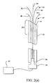
- Figure 2(b) illustrates the use of multiple sensors 36.
- Sensors 36 can be coupled to all or some of electrodes 46, 48, 50 and/or 52 at different positions of the electrodes.
- sensors are positioned at distal ends of electrodes 46 through 52, at positions that are adjacent to distal end 14 of introducer 12, and at sites that are somewhere intermediate between the distal and proximal portions of deployed lengths of the electrodes.
- Deployable member 34 can include sensors at distal and proximal portions of its deployed length in tissue site 28. The placement of sensors 36 at different locations provides a measurement of temperature and/or impedance, and a determination of the level of cell necrosis, created at tissue site 28.
- electrodes 18, 20, 46, 48, 50 and 52 can each be coupled to one or more sensors 36.
- Sensors 36 can be at exterior surfaces of electrodes 18 at their distal ends, intermediate sections as well as adjacent to distal end 14 of introducer 12.
- Some or all of electrodes 18 and deployable member 34 may have a hollow lumen by which a variety of different fluidic medium can be introduced from proximal to distal ends.
- Suitable fluidic media include but are not limited to electrolytic solutions, chemotherapeutic agents, drugs, medicaments, gene therapy agents, contrast agents and the like.
- Electrode 18, as well as deployable member 34, can have a variety of different geometric cross-sections. Electrodes 18 can be made of conductive solid or hollow straight wires of various shapes such as round, flat, triangular, rectangular, hexagonal, elliptical and the like. Figures 4 and 5 illustrate circular and elliptical cross-sections. In Figure 6, the cross-section has a greater length "L” than a width of "W”. If Figure 7, the cross-sectional is elongated. In various embodiments, the cross-sectional has a greater length than a width in order to enhance ultrasonic viewability.
- Each, a portion of all electrodes 18, as well as deployable member 34, have an exterior surface that is wholly or partially insulated and provide a non-insulated area which is an energy delivery surface.
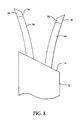
- two electrodes 18 include insulation 54.
- insulation 54 is a sleeve that can be fixed or adjustable.
- the active area of electrodes 18 is non-insulated and provides an energy delivery surface 56.
- insulation 54 is formed at the exterior of electrodes 18 in circumferential patterns, leaving a plurality of energy delivery surfaces 56.
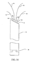
- insulation 54 extends along a longitudinal exterior surface of electrodes 18. Insulation 54 can extend along a selected distance along a longitudinal length of electrodes 18 and around a selectable portion of a circumference of electrodes 18. In various embodiments, sections of electrodes 18 can have insulation 54 along selected longitudinal lengths of electrodes 18 as well as completely surround one or more circumferential sections of electrodes 18. Insulation 54 positioned at the exterior of electrodes 18 can be varied to define any desired shape, size and geometric energy delivery surface 56.
- insulation 54 is disposed on only one section of a deployed length of electrodes 18.
- Energy delivery surfaces 56 are at distal portions of electrodes 18 as well as on longitudinal surfaces adjacent to insulation 54.
- insulation 54 extends along a longitudinal length of electrodes 18 can face toward a central axis 58 of tissue site 28 and energy delivery surface 56 faces towards in a direction toward the central axis 58.
- insulation 54 extends along a longitudinal length of electrodes 18 and faces away from central axis 58 with energy delivery surface 56 facing away from central axis 58.
- three electrodes 18 are positioned inside or outside of a periphery of tissue site 28. It will be appreciated that any number of electrodes 18 can be deployed with and without insulation to created a selectable cell necrosis pattern.
- Electrodes 18 are selectably deployable from introducer 12 with curvature to create any desired geometric area of cell necrosis.
- the selectable deployment is achieved by having electrodes 18 with, (i) different advancement lengths from introducer 12, (ii) different deployed geometric configurations, (iii) variations in cross-sectional geometries, (iv) selectable insulation provided at each and/or all of the deployed electrodes 18, or (v) the use of adjustable insulation.
- Deployed electrodes 18 can create a variety of different geometric cell necrosis zones including but not limited to spherical, semi-spherical, spheroid, triangular, semi-triangular, square, semi-square, rectangular, semi-rectangular, conical, semi-conical, quadrilateral, semi-quadrilateral, semi-quadrilateral, rhomboidal, semi-rhomboidal, trapezoidal, semi-trapezoidal, combinations of the preceding, geometries with non-planar sections or sides, free-form and the like.
- the ultrasonic visibility of electrodes 18 through is enhanced by creating a larger electrode distal end surface area 60.
- Surface area 60 is the amount of the electrode body that is at the distal end of electrodes 18. Referring now to Figure 15 the distal end of electrode 18 has at cut angle of at least 25°, and in another embodiment the cut angle is at least 30°. This creates a larger surface area 60.
- the distal end of deployable member 34 can also have these cut angles.
- each or selected electrodes 18 and deployable member 34 can have an associated spacer 62.
- Spacers 62 are advanceable from distal end 14 of introducer 12 and can be coupled to advancement member 30. Spacers 62 create a physical spacing that separates the deployed electrodes 18 from each other. The spacing created by spacers 62 also forms an area in tissue site 28 where there is reduced or very little cell necrosis.
- an insulation 64 Positioned within spacers 62 is an insulation 64 that electrically and electromagnetically isolates electrodes 18 from spacers 62.
- apparatus 10 can include a slidable member 66 that provides an electrical connection between energy delivery 16 and energy source 40.
- Slidable member 66 can be advancement member 30 or a handpiece.
- slidable member 66 has one or two electrical contact pads 68 which can be resistor strips. When slidable member is moved in a distal direction relative to distal end 14 of introducer 12 resistor strips 68 becomes engaged with a contact 70 ( Figure 18). Contact 70 is coupled to energy delivery device 16. When resistor strips 68 are engaged with contact 70, power and energy is delivered from energy source to electrodes 18.
- Slidable member 66 is then moved in a distal direction and resistor strips become un-engaged with contact 70 and the delivery of power from energy source 40 is disrupted ( Figure 19).
- the employment of slidable member 66 provides a convenient energy delivery device 16 on and off mechanism at the hand of the physician.
- Resistor strips 68 can be used as sensors to recognize a variable setting of one or all of electrodes 18 of energy delivery device 16. Resistor strips 68 can be used to measure resistance at a setting so that a change in the resistance value can be measured as slidable member 66 is moved and a corresponding change in the energy delivery surface corresponding to the electrodes 18. The resistance value can be correlated to determine an optimal power in delivering energy from energy source 40. Gap sensors, including but not limited to lasers and ultrasound, can be used to determine the variable setting.
- a feedback control system 72 is connected to energy source 40, sensors 36 and energy delivery device 16.
- Feedback control system 72 receives temperature or impedance data from sensors 36 and the amount of electromagnetic energy received by energy delivery device 16 is modified from an initial setting of cell necrosis energy output, cell necrosis time, temperature, and current density (the "Four Parameters").
- Feedback control system 72 can automatically change any of the Four Parameters.
- Feedback control system 72 can detect impedance or temperature and change any of the Four Parameters.
- Feedback control system 72 can include a multiplexer to multiplex different electrodes 18 and a temperature detection circuit that provides a control signal representative of temperature or impedance detected at one or more sensors 36.
- a microprocessor can be connected to the temperature control circuit.
- the user of apparatus 10 can input an impedance value which corresponds to a setting position located at apparatus 10. Based on this value, along with measured impedance values, feedback control system 72 determines an optimal power and time need in the delivery of RF energy. Temperature is also sensed for monitoring and feedback purposes. Temperature can be maintained to a certain level by having feedback control system 72 adjust the power output automatically to maintain that level.
- feedback control system 72 determines an optimal power and time for a baseline setting. Ablation volumes or lesions are formed at the baseline first. Larger lesions can be obtained by extending the time of ablation after a center core is formed at the baseline. A completion of lesion creation can be checked by advancing energy delivery device 16 from distal end 14 of introducer 12 to a desired lesion size and by monitoring the temperature at the periphery of the lesion.
- feedback control system 72 is programmed so the delivery of energy to energy delivery device 16 is paused at certain intervals at which time temperature is measured. By comparing measured temperatures to desired temperatures feedback control system 72 can terminate or continue the delivery of power to electrodes 18 for an appropriate length of time.
- a control signal is generated by controller 82 that is proportional to the difference between an actual measured value, and a desired value.
- the control signal is used by power circuits 84 to adjust the power output in an appropriate amount in order to maintain the desired power delivered at energy delivery device 16.
- temperatures detected at sensors 36 provide feedback for determining the extent of cell necrosis, and when a completed cell necrosis has reached the physical location of sensors 36.
- the actual temperatures are measured at temperature measurement device 86 and the temperatures are displayed at user interface and display 80.
- a control signal is generated by controller 82 that is proportional to the difference between an actual measured temperature, and a desired temperature.
- the control signal is used by power circuits 84 to adjust the power output in an appropriate amount in order to maintain the desired temperature delivered at the respective sensor 36.
- a multiplexer can be included to measure current, voltage and temperature, at the numerous sensors 36, and energy is delivered to energy delivery device 16.
- a variable electrode setting 88 is coupled to controller 82.
- Controller 82 can be a digital or analog controller, or a computer with software.
- controller 82 is a computer it can include a CPU coupled through a system bus.
- On this system can be a keyboard, a disk drive, or other non-volatile memory systems, a display, and other peripherals, as are known in the art.
- Also coupled to the bus are a program memory and a data memory.
- User interface and display 80 includes operator controls and a display.
- Controller 82 can be coupled to imaging systems, including but not limited to ultrasound, CT scanners, X-ray, MRI, mammographic X-ray and the like. Further, direct visualization and tactile imaging can be utilized.
- the output of current sensor 74 and voltage sensor 76 is used by controller 82 to maintain a selected power level at energy delivery device 16.
- the amount of RF energy delivered controls the amount of power.
- a profile of power delivered can be incorporated in controller 82, and a preset amount of energy to be delivered can also be profiled.
- Circuitry, software and feedback to controller 82 result in process control, and the maintenance of the selected power, and are used to change, (i) the selected power, including RF, microwave, laser and the like, (ii) the duty cycle (on-off and wattage), (iii) bi-polar or mono-polar energy delivery and (iv) infusion medium delivery, including flow rate and pressure.
- process variables are controlled and varied, while maintaining the desired delivery of power independent of changes in voltage or current, based on temperatures monitored at sensors 36.
- Analog amplifier 90 can be a conventional differential amplifier circuit for use with sensors 36.
- the output of analog amplifier 90 is sequentially connected by an analog multiplexer 46 to the input of A/D converter 92.
- the output of analog amplifier 90 is a voltage which represents the respective sensed temperatures.
- Digitized amplifier output voltages are supplied by A/D converter 92 to a microprocessor 96.
- Microprocessor 96 may be Model No. 68HCII available from Motorola. However, it will be appreciated that any suitable microprocessor or general purpose digital or analog computer can be used to calculate impedance or temperature.
- Microprocessor 96 sequentially receives and stores digital representations of impedance and temperature. Each digital value received by microprocessor 96 corresponds to different temperatures and impedances.
- Calculated power and impedance values can be indicated on user interface and display 80.
- calculated impedance and power values can be compared by microprocessor 96 with power and impedance limits. When the values exceed predetermined power or impedance values, a warning can be given on user interface and display 80, and additionally, the delivery of RF energy can be reduced, modified or interrupted.
- a control signal from microprocessor 96 can modify the power level supplied by energy source 40.
Abstract
Description
- This invention relates generally to a cell necrosis apparatus, and more particularly to a cell necrosis apparatus with an introducer and deployable electrodes.
- Current open procedures for treatment of tumors are extremely disruptive and cause a great deal of damage to healthy tissue. During the surgical procedure, the physician must exercise care in not cutting the tumor in a manor that creates seeding of the tumor, resulting in metastasis. In recent years, development of products has been directed with an emphasis on minimizing the traumatic nature of traditional surgical procedures.
- There has been a relatively significant amount of activity in the area of hyperthermia as a tool for treatment of tumors. It is known that elevating the temperature of tumors is helpful in the treatment and management of cancerous tissues. The mechanisms of selective cancer cell eradication by hyperthermia are not completely understood. However, four cellular effects of hyperthermia on cancerous tissue have been proposed, (i) changes in cell or nuclear membrane permeability or fluidity, (ii) cytoplasmic lysomal disintegration, causing release of digestive enzymes, (iii) protein thermal damage affecting cell respiration and the synthesis of DNA or RNA and (iv) potential excitation of immunologic systems. Treatment methods for applying heat to tumors include the use of direct contact radio-frequency (RF) applicators, microwave radiation, inductively coupled RF fields, ultrasound, and a variety of simple thermal conduction techniques.
- Among the problems associated with all of these procedures is the requirement that highly localized heat be produced at depths of several centimeters beneath the surface of the skin.
- Attempts to use interstitial local hyperthermia have not proven to be very successful. Results have often produced nonuniform temperatures throughout the tumor. It is believed that tumor mass reduction by hyperthermia is related to thermal dose. Thermal dose is the minimum effective temperature applied throughout the tumor mass for a defined period of time. Because blood flow is the major mechanism of heat loss for tumors being heated, and blood flow varies throughout the tumor, more even heating of tumor tissue is needed to ensure effective treatment.
- The same is true for ablation of the tumor itself through the use of RF energy. Different methods have been utilized for the RF ablation of masses such as tumors. Instead of heating the tumor it is ablated through the application of energy. This process has been difficult to achieve due to a variety of factors including, (i) positioning of the RF ablation electrodes to effectively ablate all of the mass, (ii) introduction of the RF ablation electrodes to the tumor site and (iii) controlled delivery and monitoring of RF energy to achieve successful ablation without damage to non-tumor tissue.
- Thus, non-invasive procedures for providing heat to internal tissue have had difficulties in achieving substantial specific and selective treatment.
- Examples illustrating the use of electromagnetic energy to ablate tissue are disclosed in: U.S. Patent No. 4,562,200; U.S. Patent No. 4,411,266; U.S. Patent No. 4,838,265; U.S. Patent No. 5,403,311; U.S. Patent No. 4,011,872; U.S. Patent No. 5,385, 544; and U.S. Patent No. 5,385,544.
- There is a need for a cell necrosis apparatus with at least two electrodes that are deployable with curvature from an introducer. There is another need for a cell necrosis apparatus with at least two electrodes that are selectably deployable with curvature from an introducer to a desired deployed geometric configuration. There is yet a further need for a cell necrosis apparatus that provides deployable electrodes that create a variety of different geometric cell necrosis lesions.
- Accordingly, an object of the invention is to provide a cell necrosis apparatus that provides tissue reduction at selected anatomical sites.
- Another object of the invention is to provide a treatment apparatus to create cell necrosis.
- Still another object of the invention is to provide a cell necrosis apparatus that has at least two electrodes which are deployable from an introducer with curvature and a third electrode which is deployable with minimal curvature.
- Yet another object of the invention is to provide a cell necrosis apparatus with selectively deployed electrodes.
- A further object of the invention is to provide a cell necrosis apparatus that is configured to deploy electrodes selectively at a tissue site to create a desired cell necrosis lesion.
- These and other objects of the invention are achieved in a cell necrosis apparatus that includes an introducer with a distal end sufficiently sharp to penetrate tissue. An energy delivery device has a first set of RF electrodes and a second set of RF electrodes. Each RF electrode of the first and second sets has a tissue piercing distal end and is positionable in the introducer as the introducer is advanced through tissue. The first and second sets of RF electrodes are deployable with curvature from the introducer. The second set of RF electrodes is deployable a greater distance from the introducer than the first set of RF electrodes.
- In another embodiment, the cell necrosis apparatus has an energy delivery device including a first RF electrode, a second RF electrode and a third RF electrode. Each of the first, second and third RF electrodes have a tissue piercing distal end and are positionable in the introducer as the introducer is advanced through tissue. The first and second RF electrodes are selectably deployable with curvature from the introducer to a tissue site. The third RF electrode is deployable from the introducer with less curvature than the first and second RF electrodes.
- In another embodiment, the cell necrosis apparatus has an energy delivery device with first and second RF electrodes. The first and second RF electrodes have tissue piercing distal ends and are positionable in the introducer as the introducer is advanced through tissue. The first and second RF electrodes are selectably advanceable with curvature from the introducer to a tissue site. A deployable member is included and has a tissue piercing distal end. The deployable member is positionable in the introducer as the introducer is advanced through tissue and deployable from the introducer with less curvature than the first and second RF electrodes. A sensor is coupled to the deployable member.
-
- Figure 1 is cross-sectional view of a cell necrosis apparatus of the present invention with two deployable electrodes and an deployable member at a selected cell necrosis tissue site.
- Figure 2(a) illustrates a cross-sectional view of an embodiment of a cell necrosis apparatus of the present invention with a first and a second set of deployable electrodes.
- Figure 2(b) illustrates the cell necrosis apparatus of Figure 2(a) positioned at a targeted cell necrosis tissue site.
- Figure 3 illustrates an embodiment of a cell necrosis apparatus of the present invention with multiple sensors coupled to electrodes.
- Figure 4 illustrates a spherical cross-section of an electrode utilized with a cell necrosis apparatus of the present invention.
- Figure 5 illustrates an elliptical cross-section of an electrode utilized with a cell necrosis apparatus of the present invention.
- Figure 6 illustrates a cross-section of an electrode utilized with a cell necrosis apparatus of the present invention with a larger cross-sectional length than its width.
- Figure 7 illustrates a cross-section of an electrode utilized with a cell necrosis apparatus of the present invention with a flat-like external surface.
- Figure 8 is a perspective view of a cell necrosis apparatus of the present invention that includes insulation sleeves positioned at exterior surfaces of the electrodes.
- Figure 9 is a perspective view of a cell necrosis apparatus of the present invention that includes multiple insulation sleeves that circumferentially insulate selected sections of the electrodes.
- Figure 10 is a perspective view of a cell necrosis apparatus of the present invention with insulation that extends along longitudinal sections of the electrodes to define adjacent longitudinal energy delivery surfaces.
- Figure 11 is a cross-sectional view of the cell necrosis apparatus of Figure 10 taken along the lines 11-11.
- Figure 12 is a perspective view of a cell necrosis apparatus of the present invention with insulation that extends along longitudinal sections of the electrodes and does not continue to distal ends of the electrodes.
- Figure 13 is a cross-sectional view illustrating the positioning of electrodes adjacent to a selected tissue site with insulation that extends along a longitudinal surface of the electrodes and the insulation faces away from a central axis of the selected tissue site.
- Figure 14 is a cross-sectional view illustrating the positioning of electrodes at a selected tissue site with insulation that extends along a longitudinal surface of the electrodes and the insulation faces toward a central axis of the selected tissue site.
- Figure 15 is a close-up perspective view of a surface area of an electrode body at a distal end of an electrode of a cell necrosis apparatus of the present invention.
- Figure 16 is a perspective view of a cell necrosis apparatus of the present invention with spacers associated with each deployed electrode.
- Figure 17 is a cross-sectional view of a cell necrosis apparatus of the present invention illustrating a spacer, an associated electrode and insulation inside the spacer.
- Figure 18 is a cross-sectional view of an embodiment of a cell necrosis apparatus of the present invention that includes a slidable member that engages a power source to a contact coupled to the electrodes.
- Figure 19 is a cross-sectional view of the apparatus of Figure 18 with the slidable member pulled back and disengaging the power source from the electrodes.
- Figure 20 is a block diagram illustrating the inclusion of a controller, electromagnetic energy source and other electronic components of the present invention.
- Figure 21 is a block diagram illustrating an analog amplifier, analog multiplexer and microprocessor used with the present invention.
-
- Referring to Figure 1, one embodiment of a
cell necrosis apparatus 10 includes anintroducer 12 with adistal end 14 sufficiently sharp to penetrate tissue. An energy delivery device, generally denoted as 16, includes afirst RF electrode 18 and asecond RF electrode 20.Electrodes introducer 12 as introducer 12 advances through tissue.Electrodes Electrodes distal end 14 or a side port formed in adistal portion 26 ofintroducer 12 to a selectedtissue site 28.Tissue site 28 can be any tissue mass and can be a tumor to be ablated.Electrodes tissue site 28 that includes internal placement, external placement at a periphery oftissue site 28 and at any desired location relative totissue site 28. The selectable deployment ofelectrodes electrodes introducer 12, independent advancement ofelectrodes introducer 12, the lengths and/or sizes of energy delivery surfaces ofelectrodes electrodes electrodes -
Electrodes introducer 12. Aselectrodes introducer 12 they move to a deployed state from their compacted configurations. Any number of electrodes can be included inenergy delivery device 16. The electrodes ofenergy delivery device 16 can be deployed simultaneously, in pairs, in sets and one at a time. Anelectrode advancement member 30 is coupled toenergy delivery device 16.Electrode advancement member 30 can be actuated by the physician by movement of aproximal end 32 relative to a longitudinal axis ofintroducer 12. -
Introducer 12 can be flexible. In one embodiment,introducer 12 is sufficiently flexible to pierce tissue, and move in any desired direction through tissue totissue site 28. In another embodiment,introducer 12 is sufficiently flexible to reverse its direction of travel and move in direction back upon itself. In one embodiment,introducer 12 is more flexible thanelectrodes - When
introducer 12reaches tissue site 28, including but not limited to a solid lesion,energy delivery device 16 is deployed preferably fromdistal end 14 ofintroducer 12.Energy delivery device 16 can also be deployed from side ports formed in the body ofintroducer 12. In the deployed stateenergy delivery device 16 becomes expanded from its compacted configuration inintroducer 12 and is selectively positioned relative totissue site 12.Electrodes tissue site 12, at the exterior oftissue site 12 as well as combinations thereof.Electrodes distal end 14 ofintroducer 12. In one embodiment, the electrodes of deployedenergy delivery device 16 are positioned equally distant a central axis oftissue site 28. Volumetric cell necrosis can proceed from the interior, exterior oftissue site 28 as well as various combinations thereof with each deployed electrode ofenergy delivery device 16 in order to create a selectable and predictable cell necrosis. -
Electrodes electrodes radiopaque marker 21 can be coated onelectrodes -
Electrodes distal end 14 ofintroducer 12. The lengths can be determined by the actual physical length ofelectrodes electrodes electrodes electrodes tissue site 28 to be ablated, its distance from the skin, its accessibility as well as whether or not the physician chooses a laparoscopic, percutaneous or other procedure. - A
deployable member 34 can be coupled toelectrode advancement member 30.Deployable member 34 can provide a variety of different functions including but not limited to the placement of a sensor at a selected tissue site to measure/monitor temperature and/or impedance. Additionally, all or a portion ofdeployable member 34 can be an RF electrode operable in bi-polar or mono-polar modes.Deployable member 34 can also be a groundpad electrode. - A
sensor 36 can be coupled todeployable member 34 at adistal end 38, or at any physical location ofdeployable member 34. In this manner, temperature and/or impedance is measured or monitored at a distal portion oftissue site 28 or at any position in or external totissue site 28.Deployable member 34 is deployable fromdistal end 14 ofintroducer 12 with less curvature thanelectrodes Deployable member 34 can be deployable fromdistal end 14 without substantially any curvature. -
Sensor 36 permits accurate measurement of temperature attissue site 28 in order to determine, (i) the extent of cell necrosis, (ii) the amount of cell necrosis, (iii) whether or not further cell necrosis is needed and (iv) the boundary or periphery of the ablated mass. Further,sensor 36 reduces non-targeted tissue from being destroyed or ablated. -
Sensor 36 is of conventional design, including but not limited to thermistors, thermocouples, resistive wires, and the like. A suitablethermal sensor 36 includes a T type thermocouple with copper constantene, J type, E type, K type, fiber optics, resistive wires, thermocouple IR detectors, and the like. It will be appreciated thatsensor 36 need not be a thermal sensor. -
Sensor 36 measures temperature and/or impedance to permit monitoring and a desired level of cell necrosis to be achieved without destroying too much tissue. This reduces damage to tissue surrounding the targeted mass to be ablated. By monitoring the temperature at various points within and outside of the interior oftissue site 28, a determination of the selected tissue mass periphery can be made, as well as a determination of when cell necrosis is complete. If at anytime sensor 36 determines that a desired cell necrosis temperature is exceeded, then an appropriate feedback signal is received at anenergy source 40 coupled toenergy delivery device 16 which then regulates the amount of electromagnetic energy delivered toelectrodes -
Energy source 40 can be an RF power supply, an ultrasound energy source, a microwave generator, a resistive heating source, a laser and the like. Microwave antenna, optical fibers, resistive heating elements and ultrasound transducers can be substituted forelectrodes energy source 40 is an RF power supply, 5 to 200 watts, preferably 5 to 100, and still more preferably 5 to 50 watts of electromagnetic energy is delivered fromenergy source 40 to the electrodes ofenergy delivery device 16 without impeding out the electrodes. -
Electrodes energy source 40. The coupling can be direct fromenergy source 40 to eachelectrode energy source 40. - Referring now to Figure 2(a), another embodiment of
apparatus 10 is shown.Apparatus 10 includes afirst set 42 of RF electrodes and asecond set 44 of RF electrodes. First andsecond sets electrodes electrodes second sets Electrodes introducer 12 in compacted states, and advanceable to deployed states fromdistal end 14 with curvature fromintroducer 12. First set 42 is deployable a greater distance fromdistal end 14 thansecond set 44. - First and
second sets electrode advancement member 30 and can be simultaneously or individually deployed fromdistal end 14. Optionally coupled tofirst set 42, second set 44 and/orelectrode advancement member 30 isdeployable member 34. Again,deployable member 34 can be coupled to asensor 36 and all or a portion ofdeployable member 34 may be an RF electrode. - Figure 2(b) illustrates the use of
multiple sensors 36.Sensors 36 can be coupled to all or some ofelectrodes electrodes 46 through 52, at positions that are adjacent todistal end 14 ofintroducer 12, and at sites that are somewhere intermediate between the distal and proximal portions of deployed lengths of the electrodes.Deployable member 34 can include sensors at distal and proximal portions of its deployed length intissue site 28. The placement ofsensors 36 at different locations provides a measurement of temperature and/or impedance, and a determination of the level of cell necrosis, created attissue site 28. - As shown in Figure 3,
electrodes electrodes 18", can each be coupled to one ormore sensors 36.Sensors 36 can be at exterior surfaces ofelectrodes 18 at their distal ends, intermediate sections as well as adjacent todistal end 14 ofintroducer 12. Some or all ofelectrodes 18 anddeployable member 34 may have a hollow lumen by which a variety of different fluidic medium can be introduced from proximal to distal ends. Suitable fluidic media include but are not limited to electrolytic solutions, chemotherapeutic agents, drugs, medicaments, gene therapy agents, contrast agents and the like. -
Electrode 18, as well asdeployable member 34, can have a variety of different geometric cross-sections.Electrodes 18 can be made of conductive solid or hollow straight wires of various shapes such as round, flat, triangular, rectangular, hexagonal, elliptical and the like. Figures 4 and 5 illustrate circular and elliptical cross-sections. In Figure 6, the cross-section has a greater length "L" than a width of "W". If Figure 7, the cross-sectional is elongated. In various embodiments, the cross-sectional has a greater length than a width in order to enhance ultrasonic viewability. - Each, a portion of all
electrodes 18, as well asdeployable member 34, have an exterior surface that is wholly or partially insulated and provide a non-insulated area which is an energy delivery surface. In Figure 8, twoelectrodes 18 includeinsulation 54. In the embodiment of Figure 8,insulation 54 is a sleeve that can be fixed or adjustable. The active area ofelectrodes 18 is non-insulated and provides anenergy delivery surface 56. - In the embodiment illustrated in Figure 9,
insulation 54 is formed at the exterior ofelectrodes 18 in circumferential patterns, leaving a plurality of energy delivery surfaces 56. Referring now to the embodiment of Figures 10 and 11,insulation 54 extends along a longitudinal exterior surface ofelectrodes 18.Insulation 54 can extend along a selected distance along a longitudinal length ofelectrodes 18 and around a selectable portion of a circumference ofelectrodes 18. In various embodiments, sections ofelectrodes 18 can haveinsulation 54 along selected longitudinal lengths ofelectrodes 18 as well as completely surround one or more circumferential sections ofelectrodes 18.Insulation 54 positioned at the exterior ofelectrodes 18 can be varied to define any desired shape, size and geometricenergy delivery surface 56. - In Figure 12,
insulation 54 is disposed on only one section of a deployed length ofelectrodes 18. Energy delivery surfaces 56 are at distal portions ofelectrodes 18 as well as on longitudinal surfaces adjacent toinsulation 54. In Figure 13,insulation 54 extends along a longitudinal length ofelectrodes 18 can face toward acentral axis 58 oftissue site 28 andenergy delivery surface 56 faces towards in a direction toward thecentral axis 58. In Figure 14,insulation 54 extends along a longitudinal length ofelectrodes 18 and faces away fromcentral axis 58 withenergy delivery surface 56 facing away fromcentral axis 58. In the embodiments illustrated in Figures 12 and 13, threeelectrodes 18 are positioned inside or outside of a periphery oftissue site 28. It will be appreciated that any number ofelectrodes 18 can be deployed with and without insulation to created a selectable cell necrosis pattern. -
Electrodes 18 are selectably deployable fromintroducer 12 with curvature to create any desired geometric area of cell necrosis. The selectable deployment is achieved by havingelectrodes 18 with, (i) different advancement lengths fromintroducer 12, (ii) different deployed geometric configurations, (iii) variations in cross-sectional geometries, (iv) selectable insulation provided at each and/or all of the deployedelectrodes 18, or (v) the use of adjustable insulation. - Deployed
electrodes 18 can create a variety of different geometric cell necrosis zones including but not limited to spherical, semi-spherical, spheroid, triangular, semi-triangular, square, semi-square, rectangular, semi-rectangular, conical, semi-conical, quadrilateral, semi-quadrilateral, semi-quadrilateral, rhomboidal, semi-rhomboidal, trapezoidal, semi-trapezoidal, combinations of the preceding, geometries with non-planar sections or sides, free-form and the like. - In one embodiment, the ultrasonic visibility of
electrodes 18 through is enhanced by creating a larger electrode distalend surface area 60.Surface area 60 is the amount of the electrode body that is at the distal end ofelectrodes 18. Referring now to Figure 15 the distal end ofelectrode 18 has at cut angle of at least 25°, and in another embodiment the cut angle is at least 30°. This creates alarger surface area 60. The distal end ofdeployable member 34 can also have these cut angles. - Referring to Figures 16 and 17, each or selected
electrodes 18 anddeployable member 34 can have an associatedspacer 62.Spacers 62 are advanceable fromdistal end 14 ofintroducer 12 and can be coupled toadvancement member 30.Spacers 62 create a physical spacing that separates the deployedelectrodes 18 from each other. The spacing created byspacers 62 also forms an area intissue site 28 where there is reduced or very little cell necrosis. Positioned withinspacers 62 is aninsulation 64 that electrically andelectromagnetically isolates electrodes 18 fromspacers 62. - As illustrates in Figures 18 and 19,
apparatus 10 can include aslidable member 66 that provides an electrical connection betweenenergy delivery 16 andenergy source 40.Slidable member 66 can beadvancement member 30 or a handpiece. In one embodiment,slidable member 66 has one or twoelectrical contact pads 68 which can be resistor strips. When slidable member is moved in a distal direction relative todistal end 14 ofintroducer 12 resistor strips 68 becomes engaged with a contact 70 (Figure 18).Contact 70 is coupled toenergy delivery device 16. When resistor strips 68 are engaged withcontact 70, power and energy is delivered from energy source toelectrodes 18.Slidable member 66 is then moved in a distal direction and resistor strips become un-engaged withcontact 70 and the delivery of power fromenergy source 40 is disrupted (Figure 19). The employment ofslidable member 66 provides a convenientenergy delivery device 16 on and off mechanism at the hand of the physician. - Resistor strips 68 can be used as sensors to recognize a variable setting of one or all of
electrodes 18 ofenergy delivery device 16. Resistor strips 68 can be used to measure resistance at a setting so that a change in the resistance value can be measured asslidable member 66 is moved and a corresponding change in the energy delivery surface corresponding to theelectrodes 18. The resistance value can be correlated to determine an optimal power in delivering energy fromenergy source 40. Gap sensors, including but not limited to lasers and ultrasound, can be used to determine the variable setting. - Referring now to Figure 20, a
feedback control system 72 is connected toenergy source 40,sensors 36 andenergy delivery device 16.Feedback control system 72 receives temperature or impedance data fromsensors 36 and the amount of electromagnetic energy received byenergy delivery device 16 is modified from an initial setting of cell necrosis energy output, cell necrosis time, temperature, and current density (the "Four Parameters").Feedback control system 72 can automatically change any of the Four Parameters.Feedback control system 72 can detect impedance or temperature and change any of the Four Parameters.Feedback control system 72 can include a multiplexer to multiplexdifferent electrodes 18 and a temperature detection circuit that provides a control signal representative of temperature or impedance detected at one ormore sensors 36. A microprocessor can be connected to the temperature control circuit. - The user of
apparatus 10 can input an impedance value which corresponds to a setting position located atapparatus 10. Based on this value, along with measured impedance values,feedback control system 72 determines an optimal power and time need in the delivery of RF energy. Temperature is also sensed for monitoring and feedback purposes. Temperature can be maintained to a certain level by havingfeedback control system 72 adjust the power output automatically to maintain that level. - In another embodiment,
feedback control system 72 determines an optimal power and time for a baseline setting. Ablation volumes or lesions are formed at the baseline first. Larger lesions can be obtained by extending the time of ablation after a center core is formed at the baseline. A completion of lesion creation can be checked by advancingenergy delivery device 16 fromdistal end 14 ofintroducer 12 to a desired lesion size and by monitoring the temperature at the periphery of the lesion. - In another embodiment,
feedback control system 72 is programmed so the delivery of energy toenergy delivery device 16 is paused at certain intervals at which time temperature is measured. By comparing measured temperatures to desired temperaturesfeedback control system 72 can terminate or continue the delivery of power toelectrodes 18 for an appropriate length of time. - The following discussion pertains particularly to the use of an RF energy source and RF electrodes but applies to other energy delivery devices and energy sources including but not limited to microwave, ultrasound, resistive heating, coherent and incoherent light, and the like.
- Current delivered to
electrodes 18 is measured by acurrent sensor 74. Voltage is measured byvoltage sensor 76. Impedance and power are then calculated at power andimpedance calculation device 78. These values can then be displayed at user interface anddisplay 80. Signals representative of power and impedance values are received bycontroller 82. - A control signal is generated by
controller 82 that is proportional to the difference between an actual measured value, and a desired value. The control signal is used bypower circuits 84 to adjust the power output in an appropriate amount in order to maintain the desired power delivered atenergy delivery device 16. - In a similar manner, temperatures detected at
sensors 36 provide feedback for determining the extent of cell necrosis, and when a completed cell necrosis has reached the physical location ofsensors 36. The actual temperatures are measured attemperature measurement device 86 and the temperatures are displayed at user interface anddisplay 80. A control signal is generated bycontroller 82 that is proportional to the difference between an actual measured temperature, and a desired temperature. The control signal is used bypower circuits 84 to adjust the power output in an appropriate amount in order to maintain the desired temperature delivered at therespective sensor 36. A multiplexer can be included to measure current, voltage and temperature, at thenumerous sensors 36, and energy is delivered toenergy delivery device 16. A variable electrode setting 88 is coupled tocontroller 82. -
Controller 82 can be a digital or analog controller, or a computer with software. Whencontroller 82 is a computer it can include a CPU coupled through a system bus. On this system can be a keyboard, a disk drive, or other non-volatile memory systems, a display, and other peripherals, as are known in the art. Also coupled to the bus are a program memory and a data memory. - User interface and
display 80 includes operator controls and a display.Controller 82 can be coupled to imaging systems, including but not limited to ultrasound, CT scanners, X-ray, MRI, mammographic X-ray and the like. Further, direct visualization and tactile imaging can be utilized. - The output of
current sensor 74 andvoltage sensor 76 is used bycontroller 82 to maintain a selected power level atenergy delivery device 16. The amount of RF energy delivered controls the amount of power. A profile of power delivered can be incorporated incontroller 82, and a preset amount of energy to be delivered can also be profiled. - Circuitry, software and feedback to
controller 82 result in process control, and the maintenance of the selected power, and are used to change, (i) the selected power, including RF, microwave, laser and the like, (ii) the duty cycle (on-off and wattage), (iii) bi-polar or mono-polar energy delivery and (iv) infusion medium delivery, including flow rate and pressure. These process variables are controlled and varied, while maintaining the desired delivery of power independent of changes in voltage or current, based on temperatures monitored atsensors 36. - Referring now to Figure 21,
current sensor 74 andvoltage sensor 76 are connected to the input of ananalog amplifier 90.Analog amplifier 90 can be a conventional differential amplifier circuit for use withsensors 36. The output ofanalog amplifier 90 is sequentially connected by ananalog multiplexer 46 to the input of A/D converter 92. The output ofanalog amplifier 90 is a voltage which represents the respective sensed temperatures. Digitized amplifier output voltages are supplied by A/D converter 92 to amicroprocessor 96.Microprocessor 96 may be Model No. 68HCII available from Motorola. However, it will be appreciated that any suitable microprocessor or general purpose digital or analog computer can be used to calculate impedance or temperature. -
Microprocessor 96 sequentially receives and stores digital representations of impedance and temperature. Each digital value received bymicroprocessor 96 corresponds to different temperatures and impedances. - Calculated power and impedance values can be indicated on user interface and
display 80. Alternatively, or in addition to the numerical indication of power or impedance, calculated impedance and power values can be compared bymicroprocessor 96 with power and impedance limits. When the values exceed predetermined power or impedance values, a warning can be given on user interface anddisplay 80, and additionally, the delivery of RF energy can be reduced, modified or interrupted. A control signal frommicroprocessor 96 can modify the power level supplied byenergy source 40. - The foregoing description of a preferred embodiment of the invention has been presented for purposes of illustration and description. It is not intended to be exhaustive or to limit the invention to the precise forms disclosed. Obviously, many modifications and variations will be apparent to practitioners skilled in this art. It is intended that the scope of the invention be defined by the following claims and their equivalents.
Claims (32)
- A cell necrosis apparatus (10) for use with an energy source (40), comprising an introducer (12) with a proximal end (32) and a distal end (14) and an energy delivery device (16) including at least a first and a second electrode (18), each electrode having a tissue piercing distal end and being positionable in the introducer as the introducer is advanced through tissue, and selectively deployable with curvature at a tissue site, further comprising:a slidable member (66) operatively coupled to the at least first and second electrodes to advance and retract the electrodes, said member being adapted for operative coupling to said energy source, and having at least one relatively movable electrode contact (70) for making and breaking electrical contact when the slidable member is advanced or retracted.
- The apparatus according to claim 1, wherein the introducer distal end is sufficiently sharp to penetrate tissue.
- The apparatus according to claim 1 or 2, wherein the energy source is selected from the group consisting of a RF energy source, a microwave energy source, an ultrasound energy source, a resistive heating source, and a laser.
- The apparatus according to any previous claim, wherein said slidable member includes at least one resistor strip (68) carried at the distal end of the slidable member, said resistor strip being adapted for operative coupling to said energy source, where the at least one contact is configured to engage the resistor strip and establish electrical contact between the resistor strip and the energy delivery device.
- The apparatus according to claim 4, wherein the at least one resistor strip includes at least a first and a second resistor strip.
- The apparatus according to claim 5, wherein the at least one contact is configured to engage at least one of the first or the second resistor strips.
- The apparatus according to any one of claims 4 to 6, wherein the at least one resistor strip is configured to measure an electrical resistance responsive to movement of at least one of the energy delivery device or the at least first and second electrodes.
- The apparatus according to claim 7, wherein the electrical resistance measurement is utilized to optimize a delivery of power to at least one of the first or second electrodes.
- The apparatus according to any previous claim, wherein the slidable member is configured to control the delivery of power to the energy delivery device from the energy source.
- The apparatus according to any previous claim, wherein the slidable member is configured to provide on and off control of power to the energy delivery device.
- The apparatus according to any previous claim, wherein said slidable member includes at least one sensor (36) for measuring a property of the energy delivery device or at least one of the first or second electrodes, wherein said at least one sensor is selected from the group consisting of a gap sensor, an ultrasonic transducer, and a laser.
- The apparatus according to claim 11, wherein the at least one sensor is at least partially positioned within a handpiece and is coupled to the proximal end of the introducer.
- The apparatus according to claim 11 or 12, wherein the at least one sensor is configured to measure a deployed length of one of the energy delivery device or at least one electrode of the first or second electrodes.
- The apparatus according to any previous claim, wherein the slidable member functions as an electrode advancement member (30).
- A cell necrosis apparatus (10) for use with an energy source (40), comprising an introducer (12) with a distal end (14) sufficiently sharp to penetrate tissue, further comprising:wherein the second set of electrodes is deployable a greater distance from the introducer than the first set of electrodes.an energy delivery device (16) including at least a first set of electrodes (42) and a second set of electrodes (44), each electrode of the first and second sets having a tissue piercing distal end, being positionable in the introducer as the introducer is advanced through tissue, and being selectively deployable with curvature at a tissue site,
- The apparatus according to claim 15, further comprising:a deployable member (34) with a tissue piercing distal end, the deployable member being positionable in the introducer as the indtroducer is advanced through tissue, the deployable member being deployable from the introducer with less curvature than the electrodes of the first and second sets of electrodes.
- The apparatus according to claim 16, wherein at least a portion of the deployable member is an electrode.
- The apparatus according to claim 16 or 17, further comprising:a sensor (36) coupled to the deployable member.
- The apparatus according to any of claims 15 to 18, further comprising:a sensor (36) coupled to at least one or (i) the energy delivery device or (ii) at least one electrode of the first or second set of electrodes.
- The apparatus according to any one of claims 16 to 19, further comrpising:an insulator (54) positioned on at least one of (i) at least a portion of the deployable member or (ii) at least a portion of at least one electrode of the first or second sets of electrodes.
- The apparatus according to any of claims 15 to 20, wherein at least one of (i) the deployable member, or (ii) at least a portion of the electrodes of the first or second set of electrode has a tissue piercing distal end that is ultrasonically viewable.
- The apparatus according to any of claims 15 to 21, further comprising:a spacer member (62) coupled to at least one electrode of the first and second set of electrodes.
- The apparatus according to claim 22, wherein the spacer member is advanceable from the introducer.
- The apparatus according to claim 22 or 23, wherein the spacer member is electrically isolated from at least one electrode of the first and second set of electrodes.
- The apparatus according to any one of claims 22 to 24, wherein at least a portion of the spacer member is an electrode.
- The apparatus according to any of claims 15 to 25, wherein the first set of electrodes includes at least a first electrode and a second electrode, and the second set includes at least a third electrode and a fourth electrode.
- The apparatus according to any of claims 15 to 26, wherein the energy source is selected from the group consisting of a RF energy source, a microwave energy source, an ultrasound energy source, a resistive heating source, and a laser.
- The apparatus according to any of claims 15 to 27, further comprising:an advancement member (30) coupled to the energy delivery device.
- The apparatus according to any of claims 15 to 28, wherein at least one of the electrodes of the first or second set of electrodes includes a hollow lumen configured to receive a fluidic medium.
- The apparatus according to any of claims 20 to 29, further comprising:a feedback control (72) coupled to the sensor and the energy source.
- The apparatus according to any of claims 15 to 30, wherein the first set of electrodes comprises at least two electrodes.
- The apparatus according to of claims 15 to 31, wherein said second set of electrodes comprises at least two electrodes.
Applications Claiming Priority (3)
| Application Number | Priority Date | Filing Date | Title |
|---|---|---|---|
| US09/148,529 US6330478B1 (en) | 1995-08-15 | 1998-09-04 | Cell necrosis apparatus |
| US148529 | 1998-09-04 | ||
| EP99949574A EP1109504B1 (en) | 1998-09-04 | 1999-08-31 | Electrosurgical device for cell necrosis induction |
Related Parent Applications (1)
| Application Number | Title | Priority Date | Filing Date |
|---|---|---|---|
| EP99949574A Division EP1109504B1 (en) | 1998-09-04 | 1999-08-31 | Electrosurgical device for cell necrosis induction |
Publications (2)
| Publication Number | Publication Date |
|---|---|
| EP1598025A2 true EP1598025A2 (en) | 2005-11-23 |
| EP1598025A3 EP1598025A3 (en) | 2006-08-02 |
Family
ID=22526158
Family Applications (2)
| Application Number | Title | Priority Date | Filing Date |
|---|---|---|---|
| EP99949574A Expired - Lifetime EP1109504B1 (en) | 1998-09-04 | 1999-08-31 | Electrosurgical device for cell necrosis induction |
| EP05075334A Withdrawn EP1598025A3 (en) | 1998-09-04 | 1999-08-31 | Electrosurgical device for cell necrosis induction |
Family Applications Before (1)
| Application Number | Title | Priority Date | Filing Date |
|---|---|---|---|
| EP99949574A Expired - Lifetime EP1109504B1 (en) | 1998-09-04 | 1999-08-31 | Electrosurgical device for cell necrosis induction |
Country Status (11)
| Country | Link |
|---|---|
| US (1) | US6330478B1 (en) |
| EP (2) | EP1109504B1 (en) |
| JP (1) | JP4191897B2 (en) |
| AT (1) | ATE431108T1 (en) |
| AU (1) | AU6241999A (en) |
| DE (1) | DE69940887D1 (en) |
| DK (1) | DK1109504T3 (en) |
| ES (1) | ES2325776T3 (en) |
| PT (1) | PT1109504E (en) |
| TW (1) | TW446566B (en) |
| WO (1) | WO2000013602A2 (en) |
Cited By (1)
| Publication number | Priority date | Publication date | Assignee | Title |
|---|---|---|---|---|
| EP1917927A1 (en) * | 2006-10-31 | 2008-05-07 | Olympus Medical Systems Corp. | High-frequency operation apparatus and method for controlling high-frequency output based on change with time of electrical parameter |
Families Citing this family (84)
| Publication number | Priority date | Publication date | Assignee | Title |
|---|---|---|---|---|
| US6464699B1 (en) * | 1997-10-10 | 2002-10-15 | Scimed Life Systems, Inc. | Method and apparatus for positioning a diagnostic or therapeutic element on body tissue and mask element for use with same |
| US6312429B1 (en) | 1998-09-01 | 2001-11-06 | Senorx, Inc. | Electrosurgical lesion location device |
| US6837885B2 (en) | 1998-05-22 | 2005-01-04 | Scimed Life Systems, Inc. | Surgical probe for supporting inflatable therapeutic devices in contact with tissue in or around body orifices and within tumors |
| US7922709B2 (en) | 1998-07-13 | 2011-04-12 | Genetronics, Inc. | Enhanced delivery of naked DNA to skin by non-invasive in vivo electroporation |
| US6678556B1 (en) * | 1998-07-13 | 2004-01-13 | Genetronics, Inc. | Electrical field therapy with reduced histopathological change in muscle |
| CA2337652C (en) * | 1998-07-13 | 2013-03-26 | Genetronics, Inc. | Skin and muscle-targeted gene therapy by pulsed electrical field |
| US6306132B1 (en) | 1999-06-17 | 2001-10-23 | Vivant Medical | Modular biopsy and microwave ablation needle delivery apparatus adapted to in situ assembly and method of use |
| US6564806B1 (en) | 2000-02-18 | 2003-05-20 | Thomas J. Fogarty | Device for accurately marking tissue |
| US6722371B1 (en) | 2000-02-18 | 2004-04-20 | Thomas J. Fogarty | Device for accurately marking tissue |
| WO2001060235A2 (en) | 2000-02-18 | 2001-08-23 | Fogarty Thomas J M D | Improved device for accurately marking tissue |
| US6770070B1 (en) * | 2000-03-17 | 2004-08-03 | Rita Medical Systems, Inc. | Lung treatment apparatus and method |
| US20020022864A1 (en) * | 2000-06-07 | 2002-02-21 | Mahvi David M. | Multipolar electrode system for radiofrequency ablation |
| US6638277B2 (en) * | 2000-07-06 | 2003-10-28 | Scimed Life Systems, Inc. | Tumor ablation needle with independently activated and independently traversing tines |
| US6669691B1 (en) | 2000-07-18 | 2003-12-30 | Scimed Life Systems, Inc. | Epicardial myocardial revascularization and denervation methods and apparatus |
| US6962587B2 (en) * | 2000-07-25 | 2005-11-08 | Rita Medical Systems, Inc. | Method for detecting and treating tumors using localized impedance measurement |
| US6706037B2 (en) * | 2000-10-24 | 2004-03-16 | Galil Medical Ltd. | Multiple cryoprobe apparatus and method |
| US20070088247A1 (en) * | 2000-10-24 | 2007-04-19 | Galil Medical Ltd. | Apparatus and method for thermal ablation of uterine fibroids |
| US20080045934A1 (en) * | 2000-10-24 | 2008-02-21 | Galil Medical Ltd. | Device and method for coordinated insertion of a plurality of cryoprobes |
| US20020068929A1 (en) * | 2000-10-24 | 2002-06-06 | Roni Zvuloni | Apparatus and method for compressing a gas, and cryosurgery system and method utilizing same |
| US20020188287A1 (en) * | 2001-05-21 | 2002-12-12 | Roni Zvuloni | Apparatus and method for cryosurgery within a body cavity |
| US20080051776A1 (en) * | 2001-05-21 | 2008-02-28 | Galil Medical Ltd. | Thin uninsulated cryoprobe and insulating probe introducer |
| US20080051774A1 (en) * | 2001-05-21 | 2008-02-28 | Galil Medical Ltd. | Device and method for coordinated insertion of a plurality of cryoprobes |
| US6994706B2 (en) | 2001-08-13 | 2006-02-07 | Minnesota Medical Physics, Llc | Apparatus and method for treatment of benign prostatic hyperplasia |
| US20030065317A1 (en) * | 2001-09-19 | 2003-04-03 | Rudie Eric N. | Microwave ablation device |
| US6878147B2 (en) | 2001-11-02 | 2005-04-12 | Vivant Medical, Inc. | High-strength microwave antenna assemblies |
| US9216053B2 (en) * | 2002-03-05 | 2015-12-22 | Avent, Inc. | Elongate member providing a variation in radiopacity |
| US6974455B2 (en) * | 2002-04-10 | 2005-12-13 | Boston Scientific Scimed, Inc. | Auto advancing radio frequency array |
| US7197363B2 (en) | 2002-04-16 | 2007-03-27 | Vivant Medical, Inc. | Microwave antenna having a curved configuration |
| US6752767B2 (en) | 2002-04-16 | 2004-06-22 | Vivant Medical, Inc. | Localization element with energized tip |
| WO2004028353A2 (en) * | 2002-09-30 | 2004-04-08 | Vanderbilt University | Optical apparatus for guided liver tumor treatment and methods |
| US20040077951A1 (en) * | 2002-07-05 | 2004-04-22 | Wei-Chiang Lin | Apparatus and methods of detection of radiation injury using optical spectroscopy |
| US20050119548A1 (en) * | 2002-07-05 | 2005-06-02 | Vanderbilt University | Method and apparatus for optical spectroscopic detection of cell and tissue death |
| AU2003268458A1 (en) * | 2002-09-05 | 2004-03-29 | Arthrocare Corporation | Methods and apparatus for treating intervertebral discs |
| US7794456B2 (en) | 2003-05-13 | 2010-09-14 | Arthrocare Corporation | Systems and methods for electrosurgical intervertebral disc replacement |
| CA2532815A1 (en) * | 2003-07-11 | 2005-01-27 | Steven A. Daniel | Thermal ablation of biological tissue |
| US7311703B2 (en) | 2003-07-18 | 2007-12-25 | Vivant Medical, Inc. | Devices and methods for cooling microwave antennas |
| US7708733B2 (en) | 2003-10-20 | 2010-05-04 | Arthrocare Corporation | Electrosurgical method and apparatus for removing tissue within a bone body |
| US7179256B2 (en) * | 2003-10-24 | 2007-02-20 | Biosense Webster, Inc. | Catheter with ablation needle and mapping assembly |
| US7155270B2 (en) * | 2003-10-24 | 2006-12-26 | Biosense Webster, Inc. | Catheter with multi-spine mapping assembly |
| US20050190982A1 (en) * | 2003-11-28 | 2005-09-01 | Matsushita Electric Industrial Co., Ltd. | Image reducing device and image reducing method |
| US8007847B2 (en) | 2004-01-13 | 2011-08-30 | Eytan Biderman | Feeding formula appliance |
| US8845635B2 (en) * | 2005-01-18 | 2014-09-30 | S.D.M.H. Pty. Ltd. | Device and method for thermal ablation of biological tissue using spherical ablation patterns |
| US7942873B2 (en) * | 2005-03-25 | 2011-05-17 | Angiodynamics, Inc. | Cavity ablation apparatus and method |
| JP2009524469A (en) * | 2006-01-26 | 2009-07-02 | ガリル メディカル リミテッド | Apparatus and method for coordinated insertion of multiple cryoprobes |
| US20070179491A1 (en) * | 2006-01-31 | 2007-08-02 | Medtronic, Inc. | Sensing needle for ablation therapy |
| US7879034B2 (en) | 2006-03-02 | 2011-02-01 | Arthrocare Corporation | Internally located return electrode electrosurgical apparatus, system and method |
| EP2012695B1 (en) * | 2006-03-31 | 2015-07-22 | Cook Medical Technologies LLC | Electrosurgical cutting device |
| US10028783B2 (en) | 2006-06-28 | 2018-07-24 | Kardium Inc. | Apparatus and method for intra-cardiac mapping and ablation |
| US9119633B2 (en) | 2006-06-28 | 2015-09-01 | Kardium Inc. | Apparatus and method for intra-cardiac mapping and ablation |
| US11389232B2 (en) | 2006-06-28 | 2022-07-19 | Kardium Inc. | Apparatus and method for intra-cardiac mapping and ablation |
| US8068921B2 (en) | 2006-09-29 | 2011-11-29 | Vivant Medical, Inc. | Microwave antenna assembly and method of using the same |
| US20080147040A1 (en) * | 2006-12-13 | 2008-06-19 | Medtronic Vascular, Inc. A Delaware Corporation | Catheters Having Linear Electrode Arrays and Their Methods of Use |
| US8562602B2 (en) | 2007-09-14 | 2013-10-22 | Lazure Technologies, Llc | Multi-layer electrode ablation probe and related methods |
| US20090076500A1 (en) * | 2007-09-14 | 2009-03-19 | Lazure Technologies, Llc | Multi-tine probe and treatment by activation of opposing tines |
| GB0718721D0 (en) * | 2007-09-25 | 2007-11-07 | Medical Device Innovations Ltd | Surgical resection apparatus |
| US8906011B2 (en) | 2007-11-16 | 2014-12-09 | Kardium Inc. | Medical device for use in bodily lumens, for example an atrium |
| US8292880B2 (en) | 2007-11-27 | 2012-10-23 | Vivant Medical, Inc. | Targeted cooling of deployable microwave antenna |
| US9949794B2 (en) | 2008-03-27 | 2018-04-24 | Covidien Lp | Microwave ablation devices including expandable antennas and methods of use |
| US8903488B2 (en) | 2009-05-28 | 2014-12-02 | Angiodynamics, Inc. | System and method for synchronizing energy delivery to the cardiac rhythm |
| US9895189B2 (en) | 2009-06-19 | 2018-02-20 | Angiodynamics, Inc. | Methods of sterilization and treating infection using irreversible electroporation |
| AU2010314930C1 (en) | 2009-11-05 | 2014-04-03 | Stratus Medical, LLC | Methods and systems for spinal radio frequency neurotomy |
| US20110238057A1 (en) * | 2010-02-16 | 2011-09-29 | Angiodynamics, Inc. | Dual Bracketed Energy Delivery Probe and Method of Use |
| WO2011146243A1 (en) | 2010-05-21 | 2011-11-24 | Nimbus Concepts, Llc | Systems and methods for tissue ablation |
| US8979838B2 (en) | 2010-05-24 | 2015-03-17 | Arthrocare Corporation | Symmetric switching electrode method and related system |
| IT1401688B1 (en) * | 2010-08-31 | 2013-08-02 | Gng S R L | MACHINE FOR DIATHERMY TREATMENTS. |
| US9700368B2 (en) | 2010-10-13 | 2017-07-11 | Angiodynamics, Inc. | System and method for electrically ablating tissue of a patient |
| US11259867B2 (en) | 2011-01-21 | 2022-03-01 | Kardium Inc. | High-density electrode-based medical device system |
| US9452016B2 (en) * | 2011-01-21 | 2016-09-27 | Kardium Inc. | Catheter system |
| CA2764494A1 (en) | 2011-01-21 | 2012-07-21 | Kardium Inc. | Enhanced medical device for use in bodily cavities, for example an atrium |
| US9480525B2 (en) | 2011-01-21 | 2016-11-01 | Kardium, Inc. | High-density electrode-based medical device system |
| WO2012100355A1 (en) * | 2011-01-30 | 2012-08-02 | University Health Network | Coil electrode for thermal therapy |
| US9078665B2 (en) | 2011-09-28 | 2015-07-14 | Angiodynamics, Inc. | Multiple treatment zone ablation probe |
| US9113931B2 (en) | 2012-01-06 | 2015-08-25 | Covidien Lp | System and method for treating tissue using an expandable antenna |
| US9119648B2 (en) | 2012-01-06 | 2015-09-01 | Covidien Lp | System and method for treating tissue using an expandable antenna |
| USD777926S1 (en) | 2012-01-20 | 2017-01-31 | Kardium Inc. | Intra-cardiac procedure device |
| USD777925S1 (en) | 2012-01-20 | 2017-01-31 | Kardium Inc. | Intra-cardiac procedure device |
| ITMI20120677A1 (en) * | 2012-04-24 | 2013-10-25 | Valentina Lara Garbagnati | ACTIVE HIGH-FREQUENCY ELECTROMAGNETIC ABLATION DEVICE |
| US20150342668A1 (en) | 2013-02-21 | 2015-12-03 | Stryker Corporation | Tissue ablation cannula and elecgtrode assembly that can be selectively operated with one or more active tips |
| US10039586B2 (en) | 2013-02-26 | 2018-08-07 | Cpsi Holdings Llc | Ablation probe with deployable sensors |
| EP3909535A1 (en) * | 2013-03-15 | 2021-11-17 | Baylis Medical Company Inc. | Electrosurgical device having a distal aperture |
| US9987082B2 (en) | 2013-09-05 | 2018-06-05 | Mitragen, Inc. | Valve treatment devices, systems, and methods |
| GB201614581D0 (en) * | 2016-08-26 | 2016-10-12 | Emblation Ltd | Microwave instrument |
| US10905492B2 (en) | 2016-11-17 | 2021-02-02 | Angiodynamics, Inc. | Techniques for irreversible electroporation using a single-pole tine-style internal device communicating with an external surface electrode |
| EP3914177A4 (en) * | 2019-01-23 | 2022-10-26 | Ablation Gen 2 Pty Ltd | Devices and methods for ablating tissue |
Citations (6)
| Publication number | Priority date | Publication date | Assignee | Title |
|---|---|---|---|---|
| US4011872A (en) | 1974-04-01 | 1977-03-15 | Olympus Optical Co., Ltd. | Electrical apparatus for treating affected part in a coeloma |
| US4411266A (en) | 1980-09-24 | 1983-10-25 | Cosman Eric R | Thermocouple radio frequency lesion electrode |
| US4562200A (en) | 1983-06-30 | 1985-12-31 | American Home Products Corporation | 5(Indolyl) and 5(2,3-dihydroindolyl) substituted aminoethanols and their use as anti-hypertensives |
| US4838265A (en) | 1985-05-24 | 1989-06-13 | Cosman Eric R | Localization device for probe placement under CT scanner imaging |
| US5385544A (en) | 1992-08-12 | 1995-01-31 | Vidamed, Inc. | BPH ablation method and apparatus |
| US5403311A (en) | 1993-03-29 | 1995-04-04 | Boston Scientific Corporation | Electro-coagulation and ablation and other electrotherapeutic treatments of body tissue |
Family Cites Families (14)
| Publication number | Priority date | Publication date | Assignee | Title |
|---|---|---|---|---|
| US5435805A (en) * | 1992-08-12 | 1995-07-25 | Vidamed, Inc. | Medical probe device with optical viewing capability |
| US5542915A (en) | 1992-08-12 | 1996-08-06 | Vidamed, Inc. | Thermal mapping catheter with ultrasound probe |
| US5370675A (en) * | 1992-08-12 | 1994-12-06 | Vidamed, Inc. | Medical probe device and method |
| US5035695A (en) * | 1987-11-30 | 1991-07-30 | Jaroy Weber, Jr. | Extendable electrocautery surgery apparatus and method |
| US5401272A (en) * | 1992-09-25 | 1995-03-28 | Envision Surgical Systems, Inc. | Multimodality probe with extendable bipolar electrodes |
| US5683384A (en) | 1993-11-08 | 1997-11-04 | Zomed | Multiple antenna ablation apparatus |
| US5558673A (en) * | 1994-09-30 | 1996-09-24 | Vidamed, Inc. | Medical probe device and method having a flexible resilient tape stylet |
| US5868740A (en) * | 1995-03-24 | 1999-02-09 | Board Of Regents-Univ Of Nebraska | Method for volumetric tissue ablation |
| US5611345A (en) * | 1995-04-24 | 1997-03-18 | Hibbeln; John F. | Medical instrument with improved ultrasonic visibility |
| SE505332C2 (en) * | 1995-05-18 | 1997-08-11 | Lund Instr Ab | Device for heat treatment of body tissue |
| US5536259A (en) * | 1995-07-28 | 1996-07-16 | Medisystems Technology Corp | Hypodermic cannula |
| DE19541566A1 (en) * | 1995-11-08 | 1997-05-15 | Laser & Med Tech Gmbh | Application system for HF surgery for interstitial thermotherapy in bipolar technology (HF-ITT) |
| US5817092A (en) * | 1995-11-09 | 1998-10-06 | Radio Therapeutics Corporation | Apparatus, system and method for delivering radio frequency energy to a treatment site |
| US5759154A (en) * | 1996-12-23 | 1998-06-02 | C. R. Bard, Inc. | Print mask technique for echogenic enhancement of a medical device |
-
1998
- 1998-09-04 US US09/148,529 patent/US6330478B1/en not_active Expired - Lifetime
-
1999
- 1999-08-31 AT AT99949574T patent/ATE431108T1/en active
- 1999-08-31 DK DK99949574T patent/DK1109504T3/en active
- 1999-08-31 PT PT99949574T patent/PT1109504E/en unknown
- 1999-08-31 DE DE69940887T patent/DE69940887D1/en not_active Expired - Lifetime
- 1999-08-31 WO PCT/US1999/020045 patent/WO2000013602A2/en active Application Filing
- 1999-08-31 EP EP99949574A patent/EP1109504B1/en not_active Expired - Lifetime
- 1999-08-31 AU AU62419/99A patent/AU6241999A/en not_active Abandoned
- 1999-08-31 EP EP05075334A patent/EP1598025A3/en not_active Withdrawn
- 1999-08-31 JP JP2000568413A patent/JP4191897B2/en not_active Expired - Fee Related
- 1999-08-31 ES ES99949574T patent/ES2325776T3/en not_active Expired - Lifetime
- 1999-09-01 TW TW088115064A patent/TW446566B/en not_active IP Right Cessation
Patent Citations (6)
| Publication number | Priority date | Publication date | Assignee | Title |
|---|---|---|---|---|
| US4011872A (en) | 1974-04-01 | 1977-03-15 | Olympus Optical Co., Ltd. | Electrical apparatus for treating affected part in a coeloma |
| US4411266A (en) | 1980-09-24 | 1983-10-25 | Cosman Eric R | Thermocouple radio frequency lesion electrode |
| US4562200A (en) | 1983-06-30 | 1985-12-31 | American Home Products Corporation | 5(Indolyl) and 5(2,3-dihydroindolyl) substituted aminoethanols and their use as anti-hypertensives |
| US4838265A (en) | 1985-05-24 | 1989-06-13 | Cosman Eric R | Localization device for probe placement under CT scanner imaging |
| US5385544A (en) | 1992-08-12 | 1995-01-31 | Vidamed, Inc. | BPH ablation method and apparatus |
| US5403311A (en) | 1993-03-29 | 1995-04-04 | Boston Scientific Corporation | Electro-coagulation and ablation and other electrotherapeutic treatments of body tissue |
Cited By (1)
| Publication number | Priority date | Publication date | Assignee | Title |
|---|---|---|---|---|
| EP1917927A1 (en) * | 2006-10-31 | 2008-05-07 | Olympus Medical Systems Corp. | High-frequency operation apparatus and method for controlling high-frequency output based on change with time of electrical parameter |
Also Published As
| Publication number | Publication date |
|---|---|
| AU6241999A (en) | 2000-03-27 |
| DK1109504T3 (en) | 2009-08-03 |
| ES2325776T3 (en) | 2009-09-16 |
| WO2000013602A2 (en) | 2000-03-16 |
| EP1598025A3 (en) | 2006-08-02 |
| DE69940887D1 (en) | 2009-06-25 |
| JP2002524129A (en) | 2002-08-06 |
| JP4191897B2 (en) | 2008-12-03 |
| EP1109504B1 (en) | 2009-05-13 |
| TW446566B (en) | 2001-07-21 |
| US6330478B1 (en) | 2001-12-11 |
| ATE431108T1 (en) | 2009-05-15 |
| EP1109504A2 (en) | 2001-06-27 |
| WO2000013602A3 (en) | 2000-07-20 |
| PT1109504E (en) | 2009-06-04 |
Similar Documents
| Publication | Publication Date | Title |
|---|---|---|
| US6551311B2 (en) | Cell necrosis apparatus and method | |
| EP1109504B1 (en) | Electrosurgical device for cell necrosis induction | |
| US6652516B1 (en) | Cell necrosis apparatus | |
| US5980517A (en) | Cell necrosis apparatus | |
| US6132425A (en) | Cell necrosis apparatus | |
| US5913855A (en) | Multiple antenna ablation apparatus and method | |
| US5728143A (en) | Multiple antenna ablation apparatus and method | |
| US5672174A (en) | Multiple antenna ablation apparatus and method | |
| US5672173A (en) | Multiple antenna ablation apparatus and method | |
| US6958062B1 (en) | Multiple antenna ablation apparatus and method | |
| US5782827A (en) | Multiple antenna ablation apparatus and method with multiple sensor feedback | |
| US8734439B2 (en) | Ablation apparatus and method | |
| US5951547A (en) | Multiple antenna ablation apparatus and method | |
| US5800484A (en) | Multiple antenna ablation apparatus with expanded electrodes | |
| US5863290A (en) | Multiple antenna ablation apparatus and method | |
| US6053937A (en) | Multiple electrode ablation apparatus and method with cooling element | |
| US5683384A (en) | Multiple antenna ablation apparatus | |
| US5925042A (en) | Multiple antenna ablation apparatus and method | |
| US5928229A (en) | Tumor ablation apparatus | |
| US5735847A (en) | Multiple antenna ablation apparatus and method with cooling element | |
| US6090105A (en) | Multiple electrode ablation apparatus and method | |
| EP1366725B1 (en) | Multiple electrode ablation apparatus | |
| US20080167649A1 (en) | Ablation apparatus and method | |
| US20050101950A1 (en) | Multiple antenna ablation apparatus and method | |
| WO1999022657A1 (en) | Multiple antenna ablation apparatus and method |
Legal Events
| Date | Code | Title | Description |
|---|---|---|---|
| PUAI | Public reference made under article 153(3) epc to a published international application that has entered the european phase |
Free format text: ORIGINAL CODE: 0009012 |
|
| 17P | Request for examination filed |
Effective date: 20050307 |
|
| AC | Divisional application: reference to earlier application |
Ref document number: 1109504 Country of ref document: EP Kind code of ref document: P |
|
| AK | Designated contracting states |
Kind code of ref document: A2 Designated state(s): AT BE CH CY DE DK ES FI FR GB GR IE IT LI LU MC NL PT SE |
|
| AX | Request for extension of the european patent |
Extension state: AL LT LV MK RO SI |
|
| PUAL | Search report despatched |
Free format text: ORIGINAL CODE: 0009013 |
|
| REG | Reference to a national code |
Ref country code: HK Ref legal event code: DE Ref document number: 1083681 Country of ref document: HK |
|
| AK | Designated contracting states |
Kind code of ref document: A3 Designated state(s): AT BE CH CY DE DK ES FI FR GB GR IE IT LI LU MC NL PT SE |
|
| AX | Request for extension of the european patent |
Extension state: AL LT LV MK RO SI |
|
| AKX | Designation fees paid |
Designated state(s): AT BE CH CY DE DK ES FI FR GB GR IE IT LI LU MC NL PT SE |
|
| 17Q | First examination report despatched |
Effective date: 20070807 |
|
| RAP1 | Party data changed (applicant data changed or rights of an application transferred) |
Owner name: RITA MEDICAL SYSTEMS, LLC |
|
| RAP1 | Party data changed (applicant data changed or rights of an application transferred) |
Owner name: ANGIODYNAMICS, INC. |
|
| STAA | Information on the status of an ep patent application or granted ep patent |
Free format text: STATUS: THE APPLICATION IS DEEMED TO BE WITHDRAWN |
|
| 18D | Application deemed to be withdrawn |
Effective date: 20100526 |
|
| REG | Reference to a national code |
Ref country code: HK Ref legal event code: WD Ref document number: 1083681 Country of ref document: HK |