EP1598951A1 - Inductive detection security system - Google Patents
Inductive detection security system Download PDFInfo
- Publication number
- EP1598951A1 EP1598951A1 EP05103446A EP05103446A EP1598951A1 EP 1598951 A1 EP1598951 A1 EP 1598951A1 EP 05103446 A EP05103446 A EP 05103446A EP 05103446 A EP05103446 A EP 05103446A EP 1598951 A1 EP1598951 A1 EP 1598951A1
- Authority
- EP
- European Patent Office
- Prior art keywords
- detection system
- target
- detector
- capacitor
- oscillating circuit
- Prior art date
- Legal status (The legal status is an assumption and is not a legal conclusion. Google has not performed a legal analysis and makes no representation as to the accuracy of the status listed.)
- Withdrawn
Links
- 238000001514 detection method Methods 0.000 title claims abstract description 50
- 230000001939 inductive effect Effects 0.000 title claims abstract description 9
- 230000010355 oscillation Effects 0.000 claims abstract description 44
- 239000003990 capacitor Substances 0.000 claims description 16
- 101100339482 Colletotrichum orbiculare (strain 104-T / ATCC 96160 / CBS 514.97 / LARS 414 / MAFF 240422) HOG1 gene Proteins 0.000 claims description 13
- 238000004804 winding Methods 0.000 claims description 5
- 125000004122 cyclic group Chemical group 0.000 claims description 3
- 230000001360 synchronised effect Effects 0.000 claims description 3
- 239000002184 metal Substances 0.000 description 5
- 230000007812 deficiency Effects 0.000 description 1
- 230000001934 delay Effects 0.000 description 1
- 230000006866 deterioration Effects 0.000 description 1
- 238000010586 diagram Methods 0.000 description 1
- 238000004519 manufacturing process Methods 0.000 description 1
- 230000011664 signaling Effects 0.000 description 1
Images
Classifications
-
- H—ELECTRICITY
- H04—ELECTRIC COMMUNICATION TECHNIQUE
- H04B—TRANSMISSION
- H04B5/00—Near-field transmission systems, e.g. inductive loop type
-
- H04B5/22—
-
- H04B5/73—
Definitions
- the present invention relates to an inductive sensing system capable of detect the presence of a target placed near an inductive proximity detector.
- the detection system must provide a safety function by being able to to differentiate a particular target from a common object.
- Such a system can especially be used in any automation requiring a security function important, for example in an access control or door closing control machine.
- Inductive Proximity Sensors are well-known contactless sensors that can detect the presence of a target, such as a metal object, when this is placed in the detection zone of the detector. They provide either a signal of binary output indicating the presence or absence of a target, an output signal analog, depending on the distance of the target from the detector. These detectors However, they are not able to differentiate a particular target, which makes them adapted for certain applications.
- the target is normally linked to a moving part of the door and the detector is placed on a fixed frame of the door.
- the system is set so that the output signal of the detector is the image of the closed state of the door, when the target linked to the moving part of the door is detected by the fixed detector on the fixed part of the door.
- the target may be substituted by any metallic object of sufficient size (such as a tool, a key, a plate, etc.) to obtain the same result. So, if we put such a metal object near the detector, the system would indicate that the door is actually closed without actually knowing the position of the movable part of the door. The security function would then no longer be fulfilled, which could cause serious deficiencies in the security of property and persons, incompatible with the EN954 standard.
- the object of the invention is to avoid such a disadvantage by proposing a system of inductive security detection that is able to differentiate a particular target by compared to a usual object, while proposing a simple, reliable and economical solution.
- the invention describes a presence detection system comprising a inductive proximity detector and a target that can be detected by the detector.
- the detector comprises a first oscillating circuit which generates a detection signal according to several different oscillation frequencies and means for processing said signal of detection.
- the target comprises a second oscillating circuit resonant at a fixed frequency substantially equal to one of the oscillation frequencies of the first oscillating circuit.
- the first oscillating circuit switches between two oscillation frequencies according to a cyclic binary switching order given by the processing means.
- the detection system provides an output signal indicating a presence of a target when the variations of the detection signal are synchronized with the variations of the switching order.
- the time interval between two changes consecutive states of the switching order is variable.
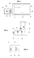
- the detection system comprises a detector of inductive proximity 10 and a target 20 that can be detected when it is located at proximity of the detector, that is to say in its detection zone.
- the detector 10 comprises an oscillating circuit 11, called the first oscillating circuit, which generates a detection signal 18 and processing means 40 which provides an output signal 41.
- the output signal is a binary signal that indicates the presence or absence of a target near the detector 10.
- the first oscillating circuit 11 is powered by an oscillator 30, for example a analog oscillator such as that shown in Figure 2 or a Namur type oscillator.
- This oscillator 30 is a current generator that sends to the first oscillating circuit 11 a current whose frequency must match the oscillation frequency of the first circuit oscillator 11.
- the oscillator 30 must not be an oscillator operating in oscillation forced.
- the processing means 40 comprise a detection stage loaded to amplify and shape the detection signal 18 received from the first oscillating circuit 11 and a processing unit to analyze this received signal and deduce the response from the detector.
- the processing means 40 also comprise an output stage which sets form and deliver the output signal 41 of the detection system, from the response developed by the processing unit.
- the first oscillating circuit 11 is composed of a coil 12 of inductance L which is connected in parallel with a variable capacitive circuit.
- the winding 12 is placed so that it can be influenced by a target placed near the detector 10.
- the variable capacitive circuit comprises a first capacitor 13 connected in parallel with a second capacitor 14, as well as a switch electronics 15 connected in series with the second capacitor 14.
- the first circuit oscillator 11 ' has a variable capacitive circuit which includes a first capacitor 13' connected in series with a second capacitor 14 'and an electronic switch 15 connected in parallel with the second capacitor 14 '.
- the electronic switch 15, which is either in an open state or a closed state, is controlled by a binary switching 19 which preferably emanates from the processing means 40.
- switch 15 may in particular include a transistor, for example of the MOS type, a triac, a thyristor, an electromechanical microsystem (MEMS) bimetallic, or others.
- MEMS electromechanical microsystem
- the first oscillating circuit 11 operates in free oscillation, that is to say that it is the value of the inductance L of the winding 12 and the value of the capacitance of the variable capacitive circuit which define the oscillation frequency F OSC of detector 10. It is therefore possible to vary this frequency thanks to the variable capacitive circuit.
- the switch 15 depending on whether the switch 15 is in the closed state or in the open state, it connects or isolates the second capacitor 14, 14 ', which modifies the value of the capacitance of the circuit capacitive variable between a value C 1 and a value C 2 .
- the values L C and C C are chosen so that the frequency F C is substantially equal to one or other of the two oscillation frequencies F OSC1 or F OSC2 .
- the first oscillating circuit 11 resonates with the second oscillating circuit 21 but only for one of the two oscillation frequencies F.
- OSC1 or F OSC2 the detection signal 18 can therefore be different according to the value of the oscillation frequency F OSC since, in the presence of a target 20, it is damped by only one of the two frequencies F OSC1 and F OSC2 .
- the winding 12 and the capacitors 13 and 14 are chosen to provide values of about 100KHz for F OSC1 and about 140KHz for F OSC2 .
- a tolerance of the order of 10% of the F C value can be perfectly tolerated to achieve proper operation of the detection system, which allows the use of inexpensive components and therefore not to penalize the system. manufacturing cost of the target 20.
- the operation of the detection system is as follows:
- the processing unit then verifies that the result of the comparison between the oscillation level V OSC of the detection signal 18 and the threshold V DET is in synchronism with the state of the switch 15 and therefore with the state of the switching order 19 sent by the processing means 40 (neglecting in particular possible delays in switching times).
- the processing unit In order for the processing unit to detect the presence of a target 20, it is necessary not only that the result of the comparison between the oscillation level V OSC and the threshold V DET change periodically, but also that these changes are synchronized with the switching order 19. In addition, any change in the periodicity of the switching command 19 must create an equivalent change in the periodicity of the detection signal 18. When the processing unit detects this synchronism, the processing means 40 then provide an output signal 41 signaling the presence of a target 20.
- the output signal 41 thus makes it possible to indicate that a target 20 has been detected (situation # 3 above), since he is able not to confuse a metal target any with the particular target as described above. This allows to respond very simply to the desired security function.
- the detection system could also provide additional information indicating that a target different metal from a target 20 was detected (situation 2), which could constitute a cause of alarm.
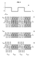
- the time interval between two consecutive changes of the switching order 19 is fixed, as shown in FIG. 4.
- variable time intervals between two consecutive changes of the order can be used for example alternations whose duration is not fixed but is calculated from a pseudo-random binary sequence stored inside the detector.
- the processing unit will then have to check the synchronism between the variations of the oscillation level Vosc and the variations of the switching order 19 to develop the output 41 of the detector, which improves the security of the system.
- the values of the frequencies F C , F OSC1 and F OSC2 are common for the different detectors and targets. However, one could also consider values F C , F OSC1 and F OSC2 that are personalized and specific to a given detection system, or to a set of given detection systems, which would be intended for example for a particular application. In such a case, a detector could be associated only with a target belonging to the same detection system or the same set of systems, further increasing the security of the system. Other combinations are obviously possible.
- the detector processing means may comprise two units of processing that each develop a distinct response to provide two signals of independent output, in order to be able to monitor a possible deterioration of one of these outputs (cut or shorted).
Abstract
Description
La présente invention se rapporte à un système de détection inductif capable de détecter la présence d'une cible placée à proximité d'un détecteur de proximité inductif. En particulier, le système de détection doit assurer une fonction de sécurité en étant capable de différencier une cible particulière par rapport à un objet usuel. Un tel système peut notamment être utilisé dans tout automatisme nécessitant une fonction de sécurité importante, par exemple dans un contrôle d'accès ou un contrôle de fermeture de porte machine.The present invention relates to an inductive sensing system capable of detect the presence of a target placed near an inductive proximity detector. In In particular, the detection system must provide a safety function by being able to to differentiate a particular target from a common object. Such a system can especially be used in any automation requiring a security function important, for example in an access control or door closing control machine.
Les détecteurs de proximité inductifs sont des capteurs sans contact bien connus qui permettent de détecter la présence d'une cible, comme un objet métallique, lorsque celle-ci est placée dans la zone de détection du détecteur. Ils fournissent soit un signal de sortie binaire indiquant la présence ou l'absence d'une cible, soit un signal de sortie analogique, en fonction de la distance de la cible par rapport au détecteur. Ces détecteurs ne sont néanmoins pas capables de différencier une cible particulière, ce qui les rend non adaptés pour certaines applications.Inductive Proximity Sensors are well-known contactless sensors that can detect the presence of a target, such as a metal object, when this is placed in the detection zone of the detector. They provide either a signal of binary output indicating the presence or absence of a target, an output signal analog, depending on the distance of the target from the detector. These detectors However, they are not able to differentiate a particular target, which makes them adapted for certain applications.
En effet, dans le cas d'une application où un système de détection est par exemple utilisé pour un contrôle de fermeture de porte, la cible est normalement liée à une partie mobile de la porte et le détecteur est placé sur un bâti fixe de la porte. Le système est paramétré pour que le signal de sortie du détecteur soit l'image de l'état fermé de la porte, quand la cible liée à la partie mobile de la porte est détectée par le détecteur fixé sur la partie fixe de la porte. Cependant avec un détecteur de proximité habituel, la cible peut être substituée par tout objet métallique quelconque de taille suffisante (comme un outil, une clef, une plaque, etc...) pour obtenir le même résultat. Ainsi, si l'on plaçait un tel objet métallique à proximité du détecteur, le système indiquerait que la porte est effectivement fermée sans connaítre réellement la position de la partie mobile de la porte. La fonction de sécurité ne serait alors évidemment plus remplie, pouvant causer des manquements graves à la sécurité des biens et des personnes, incompatibles avec la norme EN954.Indeed, in the case of an application where a detection system is example used for a door closure check, the target is normally linked to a moving part of the door and the detector is placed on a fixed frame of the door. The system is set so that the output signal of the detector is the image of the closed state of the door, when the target linked to the moving part of the door is detected by the fixed detector on the fixed part of the door. However with a usual proximity detector, the target may be substituted by any metallic object of sufficient size (such as a tool, a key, a plate, etc.) to obtain the same result. So, if we put such a metal object near the detector, the system would indicate that the door is actually closed without actually knowing the position of the movable part of the door. The security function would then no longer be fulfilled, which could cause serious deficiencies in the security of property and persons, incompatible with the EN954 standard.
Le but de l'invention est d'éviter un tel inconvénient en proposant un système de détection inductif de sécurité qui soit capable de différencier une cible particulière par rapport à un objet usuel, tout en proposant une solution simple, fiable et économique.The object of the invention is to avoid such a disadvantage by proposing a system of inductive security detection that is able to differentiate a particular target by compared to a usual object, while proposing a simple, reliable and economical solution.
Pour cela, l'invention décrit un système de détection de présence comportant un détecteur de proximité inductif et une cible susceptible d'être détectée par le détecteur. Le détecteur comprend un premier circuit oscillant qui génère un signal de détection selon plusieurs fréquences d'oscillation distinctes et des moyens de traitement dudit signal de détection. Selon une première caractéristique, la cible comporte un second circuit oscillant résonnant à une fréquence fixe sensiblement égale à l'une des fréquences d'oscillation du premier circuit oscillant.For this purpose, the invention describes a presence detection system comprising a inductive proximity detector and a target that can be detected by the detector. The detector comprises a first oscillating circuit which generates a detection signal according to several different oscillation frequencies and means for processing said signal of detection. According to a first characteristic, the target comprises a second oscillating circuit resonant at a fixed frequency substantially equal to one of the oscillation frequencies of the first oscillating circuit.
Selon une autre caractéristique, le premier circuit oscillant commute entre deux fréquences d'oscillation en fonction d'un ordre de commutation binaire cyclique donné par les moyens de traitement. Le système de détection fournit un signal de sortie indiquant une présence d'une cible lorsque les variations du signal de détection sont synchronisées avec les variations de l'ordre de commutation.According to another characteristic, the first oscillating circuit switches between two oscillation frequencies according to a cyclic binary switching order given by the processing means. The detection system provides an output signal indicating a presence of a target when the variations of the detection signal are synchronized with the variations of the switching order.
Selon une autre caractéristique, l'intervalle de temps entre deux changements d'états consécutifs de l'ordre de commutation est variable.According to another characteristic, the time interval between two changes consecutive states of the switching order is variable.
D'autres caractéristiques et avantages vont apparaítre dans la description détaillée qui suit en se référant à un mode de réalisation donné à titre d'exemple et représenté par les dessins annexés sur lesquels :
- la figure 1 représente un schéma simplifié d'un système de détection selon l'invention,
- la figure 2 détaille un premier mode de réalisation d'un premier circuit oscillant et d'un oscillateur,
- la figure 3 montre un deuxième mode de réalisation du premier circuit oscillant,
- la figure 4 donne des représentations graphiques d'un ordre de commutation et du signal de détection correspondant, dans différentes situations.
- FIG. 1 represents a simplified diagram of a detection system according to the invention,
- FIG. 2 details a first embodiment of a first oscillating circuit and an oscillator,
- FIG. 3 shows a second embodiment of the first oscillating circuit,
- Figure 4 gives graphical representations of a switching command and the corresponding detection signal in different situations.
En référence à la figure 1, le système de détection comprend un détecteur de proximité inductif 10 et une cible 20 susceptible d'être détectée lorsqu'elle est située à proximité du détecteur, c'est-à-dire dans sa zone de détection. Le détecteur 10 comporte un circuit oscillant 11, appelé premier circuit oscillant, qui génère un signal de détection 18 et des moyens de traitement 40 qui fournissent un signal de sortie 41. Le signal de sortie est un signal binaire qui indique la présence ou l'absence d'une cible 20 à proximité du détecteur 10.With reference to FIG. 1, the detection system comprises a detector of inductive proximity 10 and a target 20 that can be detected when it is located at proximity of the detector, that is to say in its detection zone. The detector 10 comprises an oscillating circuit 11, called the first oscillating circuit, which generates a detection signal 18 and processing means 40 which provides an output signal 41. The output signal is a binary signal that indicates the presence or absence of a target near the detector 10.
Le premier circuit oscillant 11 est alimenté par un oscillateur 30, par exemple un oscillateur analogique tel que celui représenté en figure 2 ou un oscillateur de type Namur. Cet oscillateur 30 est un générateur de courant qui envoie au premier circuit oscillant 11 un courant dont la fréquence doit s'accorder à la fréquence d'oscillation du premier circuit oscillant 11. L'oscillateur 30 ne doit pas être un oscillateur fonctionnant en oscillation forcée.The first oscillating circuit 11 is powered by an oscillator 30, for example a analog oscillator such as that shown in Figure 2 or a Namur type oscillator. This oscillator 30 is a current generator that sends to the first oscillating circuit 11 a current whose frequency must match the oscillation frequency of the first circuit oscillator 11. The oscillator 30 must not be an oscillator operating in oscillation forced.
Les moyens de traitement 40 comportent un étage de détection chargé d'amplifier et de mettre en forme le signal de détection 18 reçu du premier circuit oscillant 11 et une unité de traitement pour analyser ce signal reçu et en déduire la réponse du détecteur. Les moyens de traitement 40 comprennent aussi un étage de sortie qui met en forme et délivre le signal de sortie 41 du système de détection, à partir de la réponse élaborée par l'unité de traitement.The processing means 40 comprise a detection stage loaded to amplify and shape the detection signal 18 received from the first oscillating circuit 11 and a processing unit to analyze this received signal and deduce the response from the detector. The processing means 40 also comprise an output stage which sets form and deliver the output signal 41 of the detection system, from the response developed by the processing unit.
Le premier circuit oscillant 11 est composé d'un bobinage 12 d'inductance L qui est connecté en parallèle avec un circuit capacitif variable. Le bobinage 12 est placé de manière à pouvoir être influencé par une cible placée à proximité du détecteur 10. Selon une première variante, le circuit capacitif variable comprend une première capacité 13 connectée en parallèle avec une seconde capacité 14, ainsi qu'un commutateur électronique 15 raccordé en série avec la seconde capacité 14.The first oscillating circuit 11 is composed of a coil 12 of inductance L which is connected in parallel with a variable capacitive circuit. The winding 12 is placed so that it can be influenced by a target placed near the detector 10. According to a first variant, the variable capacitive circuit comprises a first capacitor 13 connected in parallel with a second capacitor 14, as well as a switch electronics 15 connected in series with the second capacitor 14.
Selon une autre variante équivalente présentée en figure 3, le premier circuit oscillant 11' possède un circuit capacitif variable qui comprend une première capacité 13' connectée en série avec une seconde capacité 14', ainsi qu'un commutateur électronique 15 raccordé en parallèle avec la seconde capacité 14'. Le commutateur électronique 15, qui se trouve soit dans un état ouvert, soit dans un état fermé, est piloté par un ordre de commutation binaire 19 qui émane préférentiellement des moyens de traitement 40. Le commutateur 15 peut notamment inclure un transistor, par exemple de type MOS, un triac, un thyristor, un microsystème électromécanique (MEMS) bilame, ou autres.According to another equivalent variant presented in FIG. 3, the first circuit oscillator 11 'has a variable capacitive circuit which includes a first capacitor 13' connected in series with a second capacitor 14 'and an electronic switch 15 connected in parallel with the second capacitor 14 '. The electronic switch 15, which is either in an open state or a closed state, is controlled by a binary switching 19 which preferably emanates from the processing means 40. switch 15 may in particular include a transistor, for example of the MOS type, a triac, a thyristor, an electromechanical microsystem (MEMS) bimetallic, or others.
Le premier circuit oscillant 11 fonctionne en oscillation libre, c'est-à-dire que ce
sont la valeur de l'inductance L du bobinage 12 et la valeur de la capacité du circuit
capacitif variable qui définissent la fréquence d'oscillation FOSC du détecteur 10. Il est donc
possible de faire varier cette fréquence grâce au circuit capacitif variable. Dans les
exemples des figures 2 et 3, suivant que le commutateur 15 se trouve à l'état fermé ou à
l'état ouvert, il connecte ou isole la seconde capacité 14,14', ce qui modifie la valeur de la
capacité du circuit capacitif variable entre une valeur C1 et une valeur C2. La fréquence
d'oscillation FOSC du détecteur varie ainsi entre deux valeurs FOSC1 et FOSC2, suivant la
formule connue :
Selon l'invention, la cible 20 comporte elle aussi un circuit oscillant 21, appelé
second circuit oscillant, qui est composé d'un bobinage 22 d'inductance LC connecté en
parallèle avec une capacité 23 de valeur CC, ce qui donne une fréquence de résonance
FC fixe égale à :
Les valeurs LC et CC sont choisies pour que la fréquence FC soit sensiblement égale à l'une ou l'autre des deux fréquences d'oscillation FOSC1 ou FOSC2. Ainsi, lorsqu'une telle cible 20 est située à l'intérieur de la zone de détection du détecteur 10, le premier circuit oscillant 11 entre en résonance avec le second circuit oscillant 21 mais seulement pour l'une des deux fréquences d'oscillation FOSC1 ou FOSC2 : le signal de détection 18 peut donc être différent suivant la valeur de la fréquence d'oscillation FOSC puisque, en présence d'une cible 20, il n'est amorti que par une seule des deux fréquences FOSC1 et FOSC2.The values L C and C C are chosen so that the frequency F C is substantially equal to one or other of the two oscillation frequencies F OSC1 or F OSC2 . Thus, when such a target 20 is located inside the detection zone of the detector 10, the first oscillating circuit 11 resonates with the second oscillating circuit 21 but only for one of the two oscillation frequencies F. OSC1 or F OSC2 : the detection signal 18 can therefore be different according to the value of the oscillation frequency F OSC since, in the presence of a target 20, it is damped by only one of the two frequencies F OSC1 and F OSC2 .
Dans un mode de réalisation de l'invention, le bobinage 12 et les capacités 13 et 14 sont choisies fournir des valeurs d'environ 100KHz pour FOSC1 et d'environ 140KHz pour FOSC2. Dans cet exemple, une tolérance de l'ordre de 10% de la valeur FC peut parfaitement être tolérée pour parvenir à un fonctionnement correct du système de détection, ce qui permet d'utiliser des composants bon marché et donc de ne pas pénaliser le coût de fabrication de la cible 20.In one embodiment of the invention, the winding 12 and the capacitors 13 and 14 are chosen to provide values of about 100KHz for F OSC1 and about 140KHz for F OSC2 . In this example, a tolerance of the order of 10% of the F C value can be perfectly tolerated to achieve proper operation of the detection system, which allows the use of inexpensive components and therefore not to penalize the system. manufacturing cost of the target 20.
Le premier circuit oscillant 11 commute alternativement entre les deux fréquences
d'oscillation FOSC1 et FOSC2 en fonction de la position du commutateur 15. Pour cela, il suffit
que les moyens de traitement 40 envoient un ordre de commutation binaire 19 cyclique
pour alterner l'ouverture et la fermeture du commutateur 15, ainsi que l'indique la première
courbe de la figure 4. L'intervalle de temps entre deux changements d'états consécutifs de
l'ordre 19 est par exemple de l'ordre de 10 ms, pour ne pas pénaliser le temps de réponse
du détecteur 10. Dans l'exemple de la figure 4, on a supposé qu'un ordre de commutation
19 égal à l'état "0" entraíne une fréquence d'oscillation du premier circuit oscillant 11 égale
à FOSC2, et qu'un ordre de commutation 19 égal à l'état "1" entraíne une fréquence
d'oscillation égale à FOSC1. Les courbes 51,52,53 de la figure 4 donnent une
représentation du signal de détection 18 dans les trois situations suivantes :
L'unité de traitement vérifie alors que le résultat de la comparaison entre le niveau d'oscillation VOSC du signal de détection 18 et le seuil VDET est en synchronisme avec l'état du commutateur 15 et donc avec l'état de l'ordre de commutation 19 envoyé par les moyens de traitement 40 (en négligeant notamment d'éventuels retards dans les temps de commutation).The processing unit then verifies that the result of the comparison between the oscillation level V OSC of the detection signal 18 and the threshold V DET is in synchronism with the state of the switch 15 and therefore with the state of the switching order 19 sent by the processing means 40 (neglecting in particular possible delays in switching times).
Pour que l'unité de traitement détecte la présence d'une cible 20, il faut non seulement que le résultat de la comparaison entre le niveau d'oscillation VOSC et le seuil VDET change périodiquement, mais aussi que ces changements soient synchronisés avec l'ordre de commutation 19. De plus, toute modification dans la périodicité de l'ordre de commutation 19 doit créer une modification équivalente dans la périodicité du signal de détection 18. Quand l'unité de traitement détecte ce synchronisme, les moyens de traitement 40 fournissent alors un signal de sortie 41 signalant la présence d'une cible 20. In order for the processing unit to detect the presence of a target 20, it is necessary not only that the result of the comparison between the oscillation level V OSC and the threshold V DET change periodically, but also that these changes are synchronized with the switching order 19. In addition, any change in the periodicity of the switching command 19 must create an equivalent change in the periodicity of the detection signal 18. When the processing unit detects this synchronism, the processing means 40 then provide an output signal 41 signaling the presence of a target 20.
Le signal de sortie 41 permet donc d'indiquer qu'une cible 20 a été détectée (situation n°3 ci-dessus), puisqu'il est capable de ne pas confondre une cible métallique quelconque avec la cible particulière 20 telle que décrite précédemment. Cela permet de répondre très simplement à la fonction de sécurisation souhaitée. Le système de détection pourrait également délivrer une information supplémentaire indiquant qu'une cible métallique différente d'une cible 20 a été détectée (situation n°2), ce qui pourrait constituer une cause d'alarme.The output signal 41 thus makes it possible to indicate that a target 20 has been detected (situation # 3 above), since he is able not to confuse a metal target any with the particular target as described above. This allows to respond very simply to the desired security function. The detection system could also provide additional information indicating that a target different metal from a target 20 was detected (situation 2), which could constitute a cause of alarm.
Dans un mode de réalisation simplifié, l'intervalle de temps entre deux changements consécutifs de l'ordre de commutation 19 est fixe, comme indiqué en figure 4. Dans un mode de réalisation apportant une sécurité renforcée, on peut envisager des intervalles de temps variables entre deux changements consécutifs de l'ordre 19. Pour cela, on peut utiliser par exemple des alternances dont la durée n'est pas fixe mais est calculée à partir d'une séquence binaire pseudo-aléatoire mémorisée à l'intérieur du détecteur. L'unité de traitement devra alors vérifier le synchronisme entre les variations du niveau d'oscillation Vosc et les variations de l'ordre de commutation 19 pour élaborer la sortie 41 du détecteur, ce qui améliore la sécurité du système.In a simplified embodiment, the time interval between two consecutive changes of the switching order 19 is fixed, as shown in FIG. 4. In one embodiment providing enhanced security, it is possible to envisage variable time intervals between two consecutive changes of the order. this can be used for example alternations whose duration is not fixed but is calculated from a pseudo-random binary sequence stored inside the detector. The processing unit will then have to check the synchronism between the variations of the oscillation level Vosc and the variations of the switching order 19 to develop the output 41 of the detector, which improves the security of the system.
Les valeurs des fréquences FC, FOSC1 et FOSC2 sont communes pour les différents détecteurs et cibles. Mais on pourrait aussi envisager des valeurs FC, FOSC1 et FOSC2 qui soient personnalisées et propres à un système de détection donné, ou à un ensemble de systèmes de détection donnés, lesquels seraient destinés par exemple à une application particulière. Dans un tel cas, un détecteur ne pourrait être associé qu'à une cible appartenant au même système de détection ou au même ensemble de systèmes, amplifiant encore la sécurisation du système. D'autres combinaisons sont évidemment possibles.The values of the frequencies F C , F OSC1 and F OSC2 are common for the different detectors and targets. However, one could also consider values F C , F OSC1 and F OSC2 that are personalized and specific to a given detection system, or to a set of given detection systems, which would be intended for example for a particular application. In such a case, a detector could be associated only with a target belonging to the same detection system or the same set of systems, further increasing the security of the system. Other combinations are obviously possible.
Lorsque le système de détection est utilisé dans un automatisme exigeant une haute sécurité, les moyens de traitement du détecteur peuvent comporter deux unités de traitement qui élaborent chacune une réponse distincte pour fournir deux signaux de sortie indépendants, de manière à pouvoir surveiller une détérioration éventuelle de l'une de ces sorties (coupée ou en court-circuit). When the detection system is used in an automation requiring a high security, the detector processing means may comprise two units of processing that each develop a distinct response to provide two signals of independent output, in order to be able to monitor a possible deterioration of one of these outputs (cut or shorted).
Il est bien entendu que l'on peut, sans sortir du cadre de l'invention, imaginer d'autres variantes et perfectionnements de détail et de même envisager l'emploi de moyens équivalents.It is understood that one can, without departing from the scope of the invention, imagine other variants and refinements of detail and even consider the use of equivalent means.
Claims (8)
Applications Claiming Priority (2)
| Application Number | Priority Date | Filing Date | Title |
|---|---|---|---|
| FR0404994A FR2870062B1 (en) | 2004-05-10 | 2004-05-10 | INDUCTIVE SAFETY DIRECTION SYSTEM |
| FR0404994 | 2004-05-10 |
Publications (1)
| Publication Number | Publication Date |
|---|---|
| EP1598951A1 true EP1598951A1 (en) | 2005-11-23 |
Family
ID=34939547
Family Applications (1)
| Application Number | Title | Priority Date | Filing Date |
|---|---|---|---|
| EP05103446A Withdrawn EP1598951A1 (en) | 2004-05-10 | 2005-04-27 | Inductive detection security system |
Country Status (2)
| Country | Link |
|---|---|
| EP (1) | EP1598951A1 (en) |
| FR (1) | FR2870062B1 (en) |
Cited By (1)
| Publication number | Priority date | Publication date | Assignee | Title |
|---|---|---|---|---|
| EP1940043A1 (en) * | 2006-12-28 | 2008-07-02 | Lineas Y Cables, S.A. | Electric power transmission system without conductors |
Citations (3)
| Publication number | Priority date | Publication date | Assignee | Title |
|---|---|---|---|---|
| US4792965A (en) * | 1987-01-29 | 1988-12-20 | Morgan Harvey L | Oscillator system for detecting a selected one of a plurality of tuned circuits |
| JPH07153589A (en) * | 1993-11-26 | 1995-06-16 | Sanyo Electric Co Ltd | Discharge lamp lighting device |
| US5962988A (en) * | 1995-11-02 | 1999-10-05 | Hubbell Incorporated | Multi-voltage ballast and dimming circuits for a lamp drive voltage transformation and ballasting system |
-
2004
- 2004-05-10 FR FR0404994A patent/FR2870062B1/en not_active Expired - Fee Related
-
2005
- 2005-04-27 EP EP05103446A patent/EP1598951A1/en not_active Withdrawn
Patent Citations (3)
| Publication number | Priority date | Publication date | Assignee | Title |
|---|---|---|---|---|
| US4792965A (en) * | 1987-01-29 | 1988-12-20 | Morgan Harvey L | Oscillator system for detecting a selected one of a plurality of tuned circuits |
| JPH07153589A (en) * | 1993-11-26 | 1995-06-16 | Sanyo Electric Co Ltd | Discharge lamp lighting device |
| US5962988A (en) * | 1995-11-02 | 1999-10-05 | Hubbell Incorporated | Multi-voltage ballast and dimming circuits for a lamp drive voltage transformation and ballasting system |
Non-Patent Citations (1)
| Title |
|---|
| PATENT ABSTRACTS OF JAPAN vol. 1995, no. 09 31 October 1995 (1995-10-31) * |
Cited By (1)
| Publication number | Priority date | Publication date | Assignee | Title |
|---|---|---|---|---|
| EP1940043A1 (en) * | 2006-12-28 | 2008-07-02 | Lineas Y Cables, S.A. | Electric power transmission system without conductors |
Also Published As
| Publication number | Publication date |
|---|---|
| FR2870062A1 (en) | 2005-11-11 |
| FR2870062B1 (en) | 2006-06-23 |
Similar Documents
| Publication | Publication Date | Title |
|---|---|---|
| FR2919072A1 (en) | INDUCTIVE PROXIMITY DETECTOR WITH SWITCHING WINDINGS. | |
| FR2949268A1 (en) | DEVICE FOR DETECTION OF ENTRY AND RECOGNITION OF TRANSPONDER BADGES, MONITORING SYSTEM COMPRISING SAME, AND SURVEILLANCE METHOD USED THEREBY | |
| FR2775350A1 (en) | DETECTOR SYSTEM FOR ACCESS CONTROL AND DETECTOR ASSEMBLY FOR IMPLEMENTING SUCH A SYSTEM | |
| EP2507739B1 (en) | Auto-configurable rfid antenna extension | |
| EP1160400B1 (en) | Switching device operating by contact of human body | |
| FR3047808B1 (en) | METHOD FOR DETECTING THE APPROACH AND / OR CONTACT OF A HAND FROM A USER TO A VEHICLE DOOR HANDLE AND DETECTION DEVICE THEREFOR | |
| EP1301898A1 (en) | Low-power passive transponder | |
| WO2019234225A1 (en) | Device for detecting intention of locking or unlocking an opening element of a motor vehicle with capacitive and inductive sensors | |
| EP2206094B1 (en) | Device for detecting the presence of a user by a vehicle | |
| FR3059499A1 (en) | METHOD FOR DETECTING APPROACH AND / OR CONTACT OF THE HAND OF A USER NEAR A DOOR HANDLE OF A MOTOR VEHICLE, CAPACITIVE SENSOR AND DETECTION MODULE THEREFOR | |
| FR2745539A1 (en) | METHOD FOR CONTROLLING AN ANTI-THEFT DEVICE AND ANTI-THEFT DEVICE CONTROLLED BY SUCH A METHOD | |
| EP1598951A1 (en) | Inductive detection security system | |
| EP1499522A1 (en) | System of controlling access to and/or the start up of a motor vehicle, comprising user alert means | |
| WO2012164179A1 (en) | Transponder positioning assistance | |
| FR2778464A1 (en) | DEVICE FOR CONTROLLING THE ANTENNA OF A SYSTEM PROVIDED IN A MOTOR VEHICLE, IN PARTICULAR A DRIVE LOCKING SYSTEM | |
| WO2008068412A1 (en) | Electronic device used for the measuring and detecting the variations of at least one input signal<0} | |
| WO2019186002A1 (en) | Device for detecting, by induction, intention of locking or unlocking an opening element of a motor vehicle with primary and secondary coils | |
| WO2016058656A1 (en) | Method for detecting proximity and/or contact and associated device | |
| FR2770563A1 (en) | DEVICE FOR RECOGNIZING A KEY ENGAGED IN A MOTOR VEHICLE LOCK | |
| FR2809759A1 (en) | Switching device operated by contact with human body, for use in particular is locking/unlocking of doors of automobile vehicles | |
| FR2673020A1 (en) | System for protecting a prohibited site against intrusions, comprising an electrified fence | |
| FR3063097A1 (en) | METHOD FOR DETERMINING PARASITE CONTACTS ON AN APPROACH DETECTION SENSOR AND / OR CONTACT SENSOR AND DEVICE FOR DETERMINING THE SAME | |
| FR2998235A1 (en) | Device for detecting hands-free access badge around car and presence of user near car door, has measurement unit measuring variation of capacity at terminals of antenna so as to represent presence of user near vehicle door | |
| EP2601741A1 (en) | Passive entry system for a vehicle | |
| EP0097661B1 (en) | Method and systems for radio telecasting for the control of a signalling or help device |
Legal Events
| Date | Code | Title | Description |
|---|---|---|---|
| PUAI | Public reference made under article 153(3) epc to a published international application that has entered the european phase |
Free format text: ORIGINAL CODE: 0009012 |
|
| AK | Designated contracting states |
Kind code of ref document: A1 Designated state(s): AT BE BG CH CY CZ DE DK EE ES FI FR GB GR HU IE IS IT LI LT LU MC NL PL PT RO SE SI SK TR |
|
| AX | Request for extension of the european patent |
Extension state: AL BA HR LV MK YU |
|
| 17P | Request for examination filed |
Effective date: 20051214 |
|
| AKX | Designation fees paid |
Designated state(s): AT BE BG CH CY CZ DE DK EE ES FI FR GB GR HU IE IS IT LI LT LU MC NL PL PT RO SE SI SK TR |
|
| STAA | Information on the status of an ep patent application or granted ep patent |
Free format text: STATUS: THE APPLICATION IS DEEMED TO BE WITHDRAWN |
|
| 18D | Application deemed to be withdrawn |
Effective date: 20060530 |