EP1600568A1 - Ground laid pipeline with protection against plant roots - Google Patents
Ground laid pipeline with protection against plant roots Download PDFInfo
- Publication number
- EP1600568A1 EP1600568A1 EP05011327A EP05011327A EP1600568A1 EP 1600568 A1 EP1600568 A1 EP 1600568A1 EP 05011327 A EP05011327 A EP 05011327A EP 05011327 A EP05011327 A EP 05011327A EP 1600568 A1 EP1600568 A1 EP 1600568A1
- Authority
- EP
- European Patent Office
- Prior art keywords
- pipe according
- additional component
- seal
- pipe
- root
- Prior art date
- Legal status (The legal status is an assumption and is not a legal conclusion. Google has not performed a legal analysis and makes no representation as to the accuracy of the status listed.)
- Withdrawn
Links
Images
Classifications
-
- F—MECHANICAL ENGINEERING; LIGHTING; HEATING; WEAPONS; BLASTING
- F16—ENGINEERING ELEMENTS AND UNITS; GENERAL MEASURES FOR PRODUCING AND MAINTAINING EFFECTIVE FUNCTIONING OF MACHINES OR INSTALLATIONS; THERMAL INSULATION IN GENERAL
- F16L—PIPES; JOINTS OR FITTINGS FOR PIPES; SUPPORTS FOR PIPES, CABLES OR PROTECTIVE TUBING; MEANS FOR THERMAL INSULATION IN GENERAL
- F16L21/00—Joints with sleeve or socket
- F16L21/02—Joints with sleeve or socket with elastic sealing rings between pipe and sleeve or between pipe and socket, e.g. with rolling or other prefabricated profiled rings
- F16L21/03—Joints with sleeve or socket with elastic sealing rings between pipe and sleeve or between pipe and socket, e.g. with rolling or other prefabricated profiled rings placed in the socket before connection
-
- F—MECHANICAL ENGINEERING; LIGHTING; HEATING; WEAPONS; BLASTING
- F16—ENGINEERING ELEMENTS AND UNITS; GENERAL MEASURES FOR PRODUCING AND MAINTAINING EFFECTIVE FUNCTIONING OF MACHINES OR INSTALLATIONS; THERMAL INSULATION IN GENERAL
- F16L—PIPES; JOINTS OR FITTINGS FOR PIPES; SUPPORTS FOR PIPES, CABLES OR PROTECTIVE TUBING; MEANS FOR THERMAL INSULATION IN GENERAL
- F16L25/00—Constructive types of pipe joints not provided for in groups F16L13/00 - F16L23/00 ; Details of pipe joints not otherwise provided for, e.g. electrically conducting or insulating means
- F16L25/0027—Joints for pipes made of reinforced concrete
Definitions
- the invention relates to an underground pipe after Preamble of claim 1.
- EP 1 477 718 A2 has a seal known on concrete pipes and shaft structures, the two made of different hard materials existing sections within its cross-section. It can be provided the softer and / or the harder material a chemically or add biologically active additive to the resistance to increase the seal against aggressive media, being also roots as such an aggressive medium be considered.
- Components with different sections are in The scope of this proposal varies according to the number of sections referred to as “two-component” or “multi-component", since they are two or more, initially separate and too with a common sealing associated components have different compositions.
- the connection the components can, for example, by positive engagement as in a tongue and groove system, by gluing or by Coextrusion.
- the sections basically consist of similar but different materials.
- each "Component” can itself consist of several substances, for example, an elastomer with several admixed Substances.
- the difference between the two components Can be mainly in the different composition of the materials, that is the chemical composition or formulation of the materials, for. B. for the purpose of different Coloring or active substance content, and / or the Both components can be mainly different have physical properties, eg. B. in terms of their Hardness.
- one-component which consists of a substantially consist of homogeneous material, which in turn consists of several Substances may exist, such as an elastomer with several admixed substances.
- piping which are used to guide Serve fluids such as gas or water pipes and Sewer channels and the like, all about horizontal but it will be called “pipeline”
- Well manhole structures understood, so essentially vertically arranged structures, for example, personnel access to a pipeline structure in the form of one of allow the aforementioned gas, water or sewage pipes, For example, for maintenance, inspection or cleaning.
- the individual pipe sections can be axial, ie longitudinal connect to each other, or they can be about Y-shaped or about T-shaped as for example in house connections abut. They can be the same or different Have diameter, and for example made of metal, from "Cast iron", of concrete, of polymer concrete, of plastic or of ceramic material, and there may be additional components be provided as for example elastomeric sealing rings or pressure transfer rings between sections of a horizontally extending pipeline, or such as made of wood or hard foam existing load transfer rings between the individual pipe sections a shaft structure.
- the invention is based on the object, a generic Improve pipeline so that its root-inhibiting Design as economically as possible and with a The best possible solution is the environment.
- the invention has the object, an annular To create a pipe component, which is such Piping allows.
- This task is performed by a pipeline with the characteristics of claim 1 and by a pipe component with the Characteristics of claim 19 solved.
- the invention proposes the pipeline by using a one-component additional component root-inhibiting design.
- the disadvantages of two-component Additional components can be avoided.
- it is proposed to wash out a root-inhibiting To reduce additional by a counter Washouts largely stable additive used becomes.
- Commercially available root-inhibiting substances enable other, comparable root-inhibiting substances a significantly better resistance to washing, z. As a between 25-fold and 220-fold lower leaching rate.
- a root-inhibiting substance dispersed in the additional component be present, for example, by this substance during the production is mixed.
- Abrasion on the surface the additional component, as he z. B. during transport or the storage of the additional component can not be excluded or at the Montagge two pipe sections inevitably the intermediate component occurs between leads, therefore not to a reduction of the protective effect as in a merely on the surface applied root-inhibiting Material.
- a commercial herbicide, which z. B. an elastomeric material can be mixed allows opposite other, comparable wurzeihemmend effective substances a significantly better resistance to washing, z. B. a 25 to 220 times lower washout rate, as practical experiments have shown.
- an outer joint closure profile can be provided be, which in addition to the seal in the groove or joint is arranged this gap closes, so between which the outer mouth of the joint and that in the joint Seal is arranged to the penetration of roots to prevent the seal.
- the seal can therefore be free of root-inhibiting substances, so that is a burden of in the pipeline guided medium washed out of the seal Root-inhibiting substances reliably excluded is.
- it can be prevented in the groove
- the roots grow and the two grow through their growth Diverge or blow up pipe sections.
- the joint closure profile can preferably be easily deformed be.
- the easy deformability allows the joint closure profile when connecting two pipe sections no hindrances, but still at both edges of the joint root can lie tightly.
- a particularly reliable connection to at least one of two adjacent pipe sections can be effected thereby be that the joint closure profile during manufacture this pipe section in a conventional manner is anchored in the material of the pipe section and for this purpose z.
- This root-inhibiting embodiment can be provided for the laying of new pipelines in which known pipe sections of z. As concrete and known Additional components z. B. used as elastomeric seals unchanged and only in addition the root-inhibiting Joint sealing profiles are used, which the joint against protect the rooting. An optimal protection of the in the Pipeline guided medium against the root-inhibiting Substances are by anyway provided elastomer seal given.
- the root-inhibiting design with the help of external joint closure profiles can also be done later by at each connection point of an already installed pipeline a joint closure profile is mounted, for. B. if the pipeline due to maintenance or repair work that is in progress anyway is exposed.
- an inner joint closure profile can be provided, which is arranged in addition to the seal in the groove or joint this gap is closed to the medium, so what between the inner mouth of the fugue and the one in the Fugue located seal is arranged to the medium of to separate the seal.
- the inner joint closure profile must Seal the groove liquid-tight, making it a secondary seal can be designated. It does, however, in the building law Meaning no seal and must be accordingly not the verifiable properties of a pipeline seal exhibit.
- the real, intended in the construction law sense and referred to as a primary seal seal can at Use of an inner joint closure profile highly effective be designed root-inhibiting, wherein that inner joint closure profile a load of the guided in the pipeline Medium with root-inhibiting substances from the seal prevents these substances from being in contact with the medium come and thus not be registered in the medium can.
- the outer or inner joint closure profile can be closed Ring be configured, z. B. for the factory or on-site attachment to individual, not yet laid Pipeline sections.
- the outer joint closure profile can be configured as an open ring, the is mounted on an already installed pipeline, or it may be segmented, with two or more, easy-to-handle items that are on a previously laid Pipeline assembled into a closed ring can be.
- the joint closure profile as Strand to be made up on a roll, of which in adaptation suitable for the respective pipe diameter Pieces are cut to length that look like an open ring on one already laid pipe can be mounted.
- a herbicide can be used which the Additional component is mixed evenly distributed. It has in practical experiments that turned out to be in use of elastomeric materials to which a commercial Herbicide is added, a good root-inhibiting effect as well as a very low leaching rate, so that z. B, in precipitation events such as a strong Rain from agricultural land significantly more herbicides be registered in the soil than from pipelines whose Additional components made of herbicides with root inhibition Elastomer materials exist.
- a coextrusion and corresponding Design as a two-component, extruded profile is not possible for rings of smaller diameter, so that In contrast, advantageously the admixture of a root inhibiting Stoffes in a one-component additional component also opened the opportunity to use it as a molded part, z. As one Make ring with a small diameter.
- the additional component can be on the Cross-section uneven distribution of root-inhibiting Be provided substances.
- the root-inhibiting substances z. B. merely by means of a nozzle projecting into the elastomer flow a place on the circumference of the seal, so that an uneven distribution over the sealing cross-section of the root-breaking substances.
- the root-inhibiting Substances z. B. first enter into the mold and then the main material - z. B. an elastomeric material - to bring in the form.
- root-inhibiting Substances Due to the uneven distribution of root-inhibiting Substances can on the side of the additional component, which to the medium is directed to the lowest possible concentration of root-inhibiting Substances are obtained while on the ground directed side of the additional component the concentration of root-inhibiting substances can be significantly higher.
- the additional component When using the additional component as a load or pressure transmission ring in a shaft construction wood can be considered as Material used.
- the root-inhibiting design This can be done by treating the wood with a herbicide impregnated or soaked.
- the pipe section shown on the right forms 2 a socket end, while the left shown Pipe section 2 a corresponding with the socket end Spiky forms into the thimble end is introduced.
- the seal 4 which is anchored in the sleeve portion, for liquid-tight sealing the pipeline 1 in this connection area.
- the seal 4 is for manufacturing reasons of the spaced outermost end face 6 of the sleeve end and continue is for manufacturing reasons a contact between a so-called mirror 7 of the spigot with this End face 6 of the socket end is not provided, so that an approximately L-shaped groove 8 results, which with a first section extends radially between the end face 6 and the mirror 7, and with a coaxially extending second section, the due to the difference in diameter between the Spigot and the socket end results, until the seal 4 runs.
- the joint closure profile 5 is provided. This is before the connection of the two pipe sections 2 on the spigot of the pipe section shown on the left 2 mounted and pressed against the mirror 7.
- the joint closure profile 5 already during the production of the pipe section 2 attach and - similar to the seal 4 is apparent - in the mirror 7 by means of appropriate, to anchor at the joint closure profile 5 provided projections.
- the joint closure profile 5 not designed as a buffer, which the mobility of the spigot in the socket end limited in it. Rather, the joint closure profile 5 has a Variety of cavities on, so it in the face of Forces when inserting one into the other pipe section 2 occur, is relatively easily deformable. These Deformability ensures that the joint closure profile 5 reliably root-tight both the mirror 7 and the End face 6 is applied, so that no gaps, joints or the like remain that the penetration of roots to the Seal 4 would allow.
- joint closure profile 5 also aware Stop or buffer to be configured, which controls the movement of the two pipe sections 2 limited to each other, so that a particularly solid investment both the end face 6 as Also ensures the mirror 7 on the joint closure profile 5 can be and thus a rooting particularly reliable can be excluded.
- joint closure profile 5 can with root-inhibiting Be provided materials, but also the other additional component 3 in the form of the seal 4, so that multiple security against the penetration of roots into the pipeline 1 given is.
- the two pipe sections can not only along one behind the other be arranged, but also at an angle to each other be aligned, z. B. at a Y-shaped branch or at a T-shaped house connection. Especially with a T-shaped house connection can be provided, the pipe sections produce at a greater time interval and Z. B. a house connection pipe made of plastic with a Diameter of about 150 mm to a much older Concrete pipe section with a considerably larger Diameter connect by first a corresponding Hole introduced into the concrete pipe section becomes.
Abstract
Description
Die Erfindung betrifft eine erdverlegbare Rohrleitung nach dem
Oberbegriff des Anspruchs 1.The invention relates to an underground pipe after
Preamble of
Aus der Praxis ist bekannt, dass ungewollter Wurzeleinwuchs ein großes Problem im Rohrleitungsbau darstellt, da er ungewollte In- und Exfiltrationen hervorrufen kann. Häufig erfolgt der Wurzeleinwuchs im Verbindungsbereich zwischen zwei Rohrleitungsabschnitten. Hierdurch wird die Rohrverbindung und damit die gesamte Rohrleitung undicht und durch Einrieseln von Erdreich sowie durch den weiteren Wurzelwuchs kann die Rohrleitung in diesem Bereich verstopfen. Nachteilig ist weiterhin einerseits, dass durch die Undichtigkeit eine Kontamination des umgebenden Erdreichs mit den in der Rohrleitung geführten Medien nicht auszuschließen ist, und andererseits, dass eindringendes Fremdwasser die der Rohrleitung nachgeschalteten Kläranlagen belastet. Wirtschaftlich ist nachteilig, dass die Beseitigung der Undichtigkeiten mit einem erheblichen Arbeits- und finanziellem Aufwand verbunden ist.From practice it is known that unwanted root ingrowth represents a major problem in pipeline construction as it is unintentional In and exfiltrations can cause. Often, the Root ingrowth in the connection area between two pipe sections. As a result, the pipe connection and thus the entire pipeline leaking and by trickling of soil as well as by the further root growth, the pipeline clog in this area. On the one hand, it is disadvantageous that through the leakage a contamination of the surrounding soil with those in the pipeline Media is not ruled out, and on the other hand, that invading Extraneous water downstream of the pipeline Wastewater treatment plants burdened. Economically it is disadvantageous that the elimination the leaks with a considerable labor and financial expense.
Aus der DE 20 2004 011 702 U1 ist es bekannt, aus Ortbeton einen Infrastruktur-Kanal mit großem freien Innenquerschnitt zu schaffen, um darin Rohrleitungen - unter anderem vor Wurzeln geschützt - zu verlegen. Der mit der Erstellung des Infrastruktur-Kanals verbundene Aufwand ist wirtschaftlich und technologisch sowie vom Platzbedarf her nachteilig.From DE 20 2004 011 702 U1 it is known from cast-site concrete an infrastructure channel with large free inner cross section too create in it pipelines - among other things before roots protected - to relocate. The one with the creation of the infrastructure channel Connected effort is economical and technological as well as the space required ago disadvantageous.
Aus der DE 33 29 100 A1 ist es bekannt, eine Rohrleitung in einer herbizidhaltigen Zone zu verlegen, bevorzugt in einer herbizidhaltigen Sandbettung, um so die Rohrleitung gegen das Eindringen von Pflanzenwurzeln zu schützen. Dabei ist nachteilig, dass ein vergleichsweise großes Materialvolumen mit Herbiziden versehen wird, welches nämlich die gesamte Rohrleitung umgibt. Da Herbizide in nicht unerheblichem Ausmaß aus Sand ausgewaschen werden können, ist bei Durchfeuchtung des Bodens, beispielsweise aufgrund von Regenfällen, ein erheblicher Eintrag der Herbizige in die Umwelt nicht auszuschließen und sogar sehr wahrscheinlich. Dies stellt sowohl eine unerwünschte Beeinträchtigung der Umwelt dar als auch eine Reduzierung der wurzelhemmenden Wirkung des die Rohrleitung umgebenden MaterialsFrom DE 33 29 100 A1 it is known, a pipeline in a To lay herbicidal zone, preferably in a herbicidal Sand bedding, so as to prevent the pipe from penetrating protect from plant roots. It is disadvantageous that a comparatively large volume of material with herbicides is provided, which is the entire pipeline surrounds. Since herbicides in sand to a considerable extent can be washed out when the soil is soaked For example, due to rainfall, a significant Entry of herbicides into the environment can not be ruled out and even very likely. This is both an undesirable Impact on the environment as well as a reduction of root-inhibiting effect of surrounding the pipeline material
Aus der nachveröffentlichten EP 1 477 718 A2 ist eine Abdichtung
an Betonrohren und Schachtbauwerken bekannt, die zwei
aus unterschiedlich harten Materialien bestehende Abschnitte
innerhalb ihres Querschnitts aufweist. Es kann vorgesehen sein,
dem weicheren und/oder dem härteren Material ein chemisch
oder biologisch wirksames Additiv zuzusetzen, um die Widerstandskraft
der Dichtung gegen aggressiven Medien zu erhöhen,
wobei auch Wurzeln als ein solches aggressives Medium
angesehen werden.The subsequently published
Bauteile mit unterschiedlichen Abschnitten, wie die vorbeschriebenen
Abdichtungen gemäß der EP 1 477 718 A2, werden im
Rahmen des vorliegenden Vorschlags je nach Anzahl der Abschnitte
als "zweikomponentig" oder "mehrkomponentig" bezeichnet,
da sie zwei oder mehrere, zunächst getrennte und zu
einer gemeinsamen Abdichtung verbundene Komponenten mit
unterschiedlichen Zusammensetzungen aufweisen. Die Verbindung
der Komponenten kann beispielsweise durch Formschluss
wie bei einem Nut-Feder-System, durch Verklebung oder durch
Koextrusion erfolgen. Die Abschnitte bestehen aus grundsätzlich
ähnlichen, aber doch unterschiedlichen Materialien. Jede
"Komponente" kann dabei selbst aus mehreren Stoffen bestehen,
beispielsweise einem Elastomer mit mehreren beigemischten
Stoffen. Die Unterschiedlichkeit der beiden Komponenten
kann hauptsächlich in der unterschiedlichen Zusammensetzung
der Materialien bestehen, also der chemischen Zusammensetzung
bzw. Formulierung der Materialien, z. B. zum Zwecke unterschiedlicher
Farbgebung oder Wirkstoffinhalte, und / oder die
beiden Komponenten können hauptsächlich unterschiedliche
physikalische Eigenschaften aufweisen, z. B. hinsichtlich ihrer
Härte.Components with different sections, such as those described above
Seals according to
Im Unterschied zu derartigen "zweikomponentigen" Bauteilen werden im Rahmen des vorliegenden Vorschlags solche Bauteile als "einkomponentig" bezeichnet, die aus einem im wesentlichen homogenen Werkstoff bestehen, der seinerseits aus mehreren Stoffen bestehen kann, beispielsweise einem Elastomer mit mehreren beigemischten Stoffen.In contrast to such "two-component" components Within the scope of the present proposal, such components will be used referred to as "one-component", which consists of a substantially consist of homogeneous material, which in turn consists of several Substances may exist, such as an elastomer with several admixed substances.
Angesichts der harten und weichen Komponenten der gemäß
der EP 1 477 718 A2 vorgeschlagenen zweikomponentigen Abdichtung
kann in der Praxis das Problem auftreten, dass eine
bestimmte Verformungscharakteristik der weichen Komponente,
die baurechtlich für eine Abdichtung gefordert sein kann, durch
die harte Komponente beeinträchtigt wird. Dies ist insbesondere
dann nicht auszuschließen, wenn die harte Komponente die
weiche Kompoente stützt und sich die weiche Komponente
dementsprechend in Nähe der harten Komponente "härter" verhält
als wenn derselbe Dichtungsprofilquerschnitt aus ausschließlich
weichem Material gebildet wäre. Es kann daher gegebenenfalls
nicht über den gesamten Querschnitt, in welchem
weiches Material vorgesehen ist, das für eine zuverlässige Abdichtung
gewünschte "weiche" Materialverhalten sichergestellt
werden. Given the hard and soft components of the
Für die baurechtlichen Zulassungen von Bauelementen - wie z. B. für einen Dichtungsring einer Rohrleitung -wird jeweils ein bestimmter Werkstoff geprüft. Ein zweikornponentiges Bauteil, wie z. B. ein aus zwei koextrudierten Materialien bestehender Dichtungsring, macht daher zwei Materialprüfungen erforderlich. Bei zwei- oder mehrkomponentigen Bauelementen ist demzufolge nachteilig, dass die Kosten für die baurechtliche Zulassung deutlich höher sind als für ein "einkomponentiges" Bauelement und mit der Anzahl der unterschiedlichen Komponenten steigen.For the construction law approvals of components - such. B. for a sealing ring of a pipeline -will each one tested certain material. A two-component component, such as B. one of two coextruded materials existing Sealing ring, therefore requires two material tests. In two- or multi-component components is therefore disadvantageous that the cost of building permit are significantly higher than for a "one-component" component and increase with the number of different components.
Im Rahmen des vorliegenden Vorschlages werden nicht nur solche Bauten als "Rohrleitung" bezeichnet, die zum Führen von Fluiden dienen, wie beispielsweise Gas- oder Wasserrohre sowie Abwasserkanäle und dergleichen, die sämtlich etwa horizontal verlaufen, sondern es werden unter dem Begriff der "Rohrleitung" auch Schachtbauwerke verstanden, also im wesentlichen senkrecht angeordnete Bauwerke, die beispielsweise Personal den Zugang zu einem Rohrleitungsbauwerk in Form eines der vorgenannten Gas-, Wasser- oder Abwasserrohre ermöglichen, beispielsweise zu Wartungs-, Inspektions- oder Reinigungsarbeiten.The present proposal does not just deal with such Buildings referred to as "piping", which are used to guide Serve fluids such as gas or water pipes and Sewer channels and the like, all about horizontal but it will be called "pipeline" Well manhole structures understood, so essentially vertically arranged structures, for example, personnel access to a pipeline structure in the form of one of allow the aforementioned gas, water or sewage pipes, For example, for maintenance, inspection or cleaning.
Die einzelnen Rohrleitungsabschnitte können axial, also längs aneinander anschließen, oder sie können etwa Y-förmig oder etwa T-förmig wie beispielsweise bei Hausanschlüssen aneinanderstoßen. Sie können gleiche oder unterschiedliche Durchmesser aufweisen, und beispielsweise aus Metall, aus "Guss", aus Beton, aus Polymerbeton, aus Kunststoff oder aus keramischem Material bestehen, und es können Zusatzbauteile vorgesehen sein wie beispielsweise elastomere Dichtungsringe oder Druck-Übertragungsringe zwischen den Abschnitten einer horizontal verlaufenden Rohrleitung, oder wie beispielsweise aus Holz oder aus Hartschaum bestehende Last-Übertragungsringe zwischen den einzelnen Rohrleitungsabschnitten eines Schachtbauwerkes. The individual pipe sections can be axial, ie longitudinal connect to each other, or they can be about Y-shaped or about T-shaped as for example in house connections abut. They can be the same or different Have diameter, and for example made of metal, from "Cast iron", of concrete, of polymer concrete, of plastic or of ceramic material, and there may be additional components be provided as for example elastomeric sealing rings or pressure transfer rings between sections of a horizontally extending pipeline, or such as made of wood or hard foam existing load transfer rings between the individual pipe sections a shaft structure.
Der Erfindung liegt die Aufgabe zugrunde, eine gattungsgemäße Rohrleitung dahingehend zu verbessern, dass deren wurzelhemmende Ausgestaltung möglichst wirtschaftlich und mit einer möglichst guten Schnonung der Umwelt ermöglicht wird. Weiterhin liegt der Erfindung die Aufgabe zugrunde, ein ringförmiges Rohrleitungs-Bauteil zu schaffen, welches eine derartige Rohrleitung ermöglicht.The invention is based on the object, a generic Improve pipeline so that its root-inhibiting Design as economically as possible and with a The best possible solution is the environment. Farther the invention has the object, an annular To create a pipe component, which is such Piping allows.
Diese Aufgabe wird durch eine Rohrleitung mit den Merkmalen
des Anspruchs 1 und durch ein Rohrleitungs-Bauteil mit den
Merkmalen des Anspruchs 19 gelöst.This task is performed by a pipeline with the characteristics
of
Die Erfindung schlägt mit anderen Worten vor, die Rohrleitung durch Verwendung eines einkomponentigen Zusatz-Bauteils wurzelhemmend auszugestalten. Die Nachteile zweikomponentiger Zusatz-Bauteile können dadurch vermieden werden. Gleichzeitig wird vorgeschlagen, das Auswaschen eines wurzelhemmenden Zusatzes dadurch zu reduzieren, dass ein gegen Auswaschungen weitgehend beständiger Zusatz verwendet wird. Handelsübliche wurzelhemmende Stoffe ermöglichen gegenüber anderen, vergleichbar wurzelhemmend wirksamen Stoffen eine deutlich bessere Beständigkeit gegen Auswaschen, z. B. eine zwischen 25-fach und 220-fach geringere Auswaschrate.In other words, the invention proposes the pipeline by using a one-component additional component root-inhibiting design. The disadvantages of two-component Additional components can be avoided. At the same time it is proposed to wash out a root-inhibiting To reduce additional by a counter Washouts largely stable additive used becomes. Commercially available root-inhibiting substances enable other, comparable root-inhibiting substances a significantly better resistance to washing, z. As a between 25-fold and 220-fold lower leaching rate.
Es ist bekannt, in den Verbindungsbereichen jeweils zweier Rohrleitungsabschnitte die Elastomerdichtungsprofile des einen oder die damit zusammenwirkenden Flächen des anderen Rohrleitungsabschnitts mit einem Gleitmittel zu versehen. Vorschlagsgemäß kann vorgesehen sein, diesem Gleitmittel einen wurzelhemmenden Stoff beizumischen, so dass hierdurch eine wurzelhemmende Ausgestaltung insbesondere des Verbindungsbereichs zwischen zwei Rohrleitungsabschnitten bewirkt wird. It is known in the connecting areas of each two Pipe sections the elastomer sealing profiles of one or the cooperating surfaces of the other pipe section to be provided with a lubricant. According to the proposal can be provided, this lubricant a to mix root-inhibiting substance, so that thereby a root-inhibiting design, in particular of the connection area effected between two pipe sections becomes.
Vorteilhaft kann ein wurzelhemmender Stoff fein verteilt im Zusatz-Bauteil vorliegen, beispielsweise indem dieser Stoff während der Produktion beigemischt wird. Abrieb an der Oberfläche des Zusatz-Bauteils, wie er z. B. während des Transports oder der Lagerung des Zusatz-Bauteils nicht auszuschließen ist oder bei der Monatge zweier Rohrleitungsabschnitte zwangsläufig an dem dazwischen befindlichen Zusatz-Bauteil auftritt, führt daher nicht zu einer Verringerung der Schutzwirkung wie bei einem lediglich an der Oberfläche aufgetragenen wurzelhemmenden Stoff. Ein handelsübliches Herbizid, welches z. B. einem Elastomer-Werkstoff zugemischt werden kann, ermöglicht gegenüber anderen, vergleichbar wurzeihemmend wirksamen Stoffen eine deutlich bessere Beständigkeit gegen Auswaschen, z. B. eine zwischen 25-fach und 220-fach geringere Auswaschrate, wie praktische Versuche ergeben haben.Advantageously, a root-inhibiting substance dispersed in the additional component be present, for example, by this substance during the production is mixed. Abrasion on the surface the additional component, as he z. B. during transport or the storage of the additional component can not be excluded or at the Montagge two pipe sections inevitably the intermediate component occurs between leads, therefore not to a reduction of the protective effect as in a merely on the surface applied root-inhibiting Material. A commercial herbicide, which z. B. an elastomeric material can be mixed, allows opposite other, comparable wurzeihemmend effective substances a significantly better resistance to washing, z. B. a 25 to 220 times lower washout rate, as practical experiments have shown.
Neuere Erkenntnisse lassen darauf schließen, dass Wurzeln bevorzugt dorthin wachsen, wo dem Wurzelwachstum innerhalb des Erdreichs ein möglichst geringer Widerstand entgegengesetzt wird. Bei einer Rohrleitung, die aus mehreren Rohrleitungsabschnitten gebildet ist, von denen jeder Rohrleitungsabschnitt jeweils ein Spitzende und ein Muffenende aufweist, ist konstruktiv bedingt stets eine äußere Stoßfuge zwischen der Stirnfläche der Muffe und dem Spitzende vorgesehen. Die Dichtung ist stets im Abstand von der radial äußeren Mündung der äußeren Stoßfuge angeordnet. Von dieser Mündung der äußeren Stoßfuge ergibt sich somit eine umlaufende Nut, die bis zu der Dichtung reicht. Da bei der Verlegung einer Rohrleitung, insbesondere beim Einbringen einer Verfüllmasse, nicht darauf geachtet wird, diese umlaufende Nut auszufüllen, ergeben sich ausgerechnet an den Stellen der Rohrleitung, die gegenüber Eindringversuchen von Wurzeln besonders empfindlich sind, die für Wurzeln bevorzugten Wachstumsbedingungen. Recent findings suggest that roots prefer to grow there, where root growth within of the soil as opposed to the least possible resistance becomes. For a pipeline that consists of several pipe sections is formed, each of which pipe section each has a spigot and a socket end, is structurally always an outer butt joint between the Face of the sleeve and the spigot provided. The seal is always at a distance from the radially outer mouth of the arranged on the outer butt joint. From this mouth of the outer Butt joint thus results in a circumferential groove, which up to the seal is enough. As in the laying of a pipeline, in particular when introducing a filling compound, not on it care is taken to fill in this circumferential groove arise just at the points of the pipeline, opposite Intrusion attempts are particularly sensitive to roots that for roots preferred growth conditions.
Es kann daher vorteilhaft vorgesehen sein, einen regelrechten Fugenverschluss zu bewirken und diese vorerwähnte ringförmig umlaufende Nut zu verschließen.It can therefore be advantageously provided a proper To cause joint closure and this aforementioned annular to close the circumferential groove.
Hierzu kann ein äußeres Fugenverschlussprofil vorgesehen sein, welches zusätzlich zu der Dichtung in der Nut bzw. Fuge angeordnet wird diese Fuge verschließt, also welches zwischen der äußeren Mündung der Fuge und der in der Fuge befindlichen Dichtung angeordnet ist, um das Vordringen von Wurzeln bis zur Dichtung zu verhindern. Die Dichtung kann daher frei von wurzelhemmenden Stoffen sein, so dass eine Belastung des in der Rohrleitung geführten Mediums mit aus der Dichtung ausgewaschenen wurzelhemmenden Stoffe zuverlässig ausgeschlossen ist.For this purpose, an outer joint closure profile can be provided be, which in addition to the seal in the groove or joint is arranged this gap closes, so between which the outer mouth of the joint and that in the joint Seal is arranged to the penetration of roots to prevent the seal. The seal can therefore be free of root-inhibiting substances, so that is a burden of in the pipeline guided medium washed out of the seal Root-inhibiting substances reliably excluded is.
Vorteilhaft kann das äußere Fugenverschlussprofil bis an die Mündung der Nut reichen bzw. an dieser Mündung angeordnet sein, so dass nicht nur die Dichtung vor den Wurzeln geschützt ist, sondern auch bereits das Eindringen von Wurzeln in die Nut verhindert wird. Somit kann verhindert werden, dass in der Nut befindliche Wurzeln wachsen und durch ihr Wachstum die beiden Rohrleitungsabschnitte auseinander drängen oder sprengen.Advantageously, the outer joint closure profile up to the Mouth of the groove rich or arranged at this mouth so that not only the seal protected from the roots is, but also already the penetration of roots in the groove is prevented. Thus, it can be prevented in the groove The roots grow and the two grow through their growth Diverge or blow up pipe sections.
Vorteilhaft kann das äußere Fugenverschlussprofil die umlaufende Nut, also den Zwischenraum zwischen Rohrende und Spitzende, möglichst vollständig ausfüllen, also von deren äußerer Mündung bis zur Dichtung verlaufen, so dass auch bei einer zunächst teilweise eingedrungenen Wurzel deren weiteres Wachstum in Richtung der Dichtung und damit in den Innenraum der Rohrleitung möglichst stark behindert oder ganz ausgeschlossen wird.Advantageously, the outer joint closure profile, the circumferential Groove, so the space between the pipe end and Spiky, as complete as possible, so from the outside Muzzle to seal run, so even at a initially partially penetrated root their further Growth in the direction of the seal and thus in the interior the pipeline as much as possible obstructed or completely excluded becomes.
Das Fugenverschlussprofil kann vorzugsweise leicht verformbar sein. Die leichte Verformbarkeit ermöglicht, dass das Fugenverschlussprofil beim Verbinden zweier Rohrleitungsabschnitte keinen hinderlichen Widerstand bietet, aber dennoch beiden Fugenrändern wurzeldicht anliegen kann.The joint closure profile can preferably be easily deformed be. The easy deformability allows the joint closure profile when connecting two pipe sections no hindrances, but still at both edges of the joint root can lie tightly.
Die leichte Verformbarkeit kann dadurch bewirkt werden, dass das Fugenverschlussprofil
- als Hohlprofil ausgestaltet ist, z. B. mit einem etwa C-förmigen oder etwa Ω-förmigen Querschnitt,
- oder als Hohlkammerprofil, mit einem allseits geschlossenen Querschnitt, und einem darin vorgesehenen Hohlraum,
- mit mehreren Rippen, die z. B. an der Oberfläche des Profils vorgesehen sind oder die z. B. in Form eines etwa "tannenbaumartigen" Profilquerschnitts vorgesehen sind,
- aus einem geschlossenporigen oder offenporigen Schaumwerkstoff besteht, also aus offenzelligen oder geschlossenzelligen Werkstoffen.
- is designed as a hollow profile, z. B. with an approximately C-shaped or approximately Ω-shaped cross-section,
- or as a hollow chamber profile, with an all-round cross-section, and a cavity provided therein,
- with several ribs, the z. B. are provided on the surface of the profile or z. B. are provided in the form of a "fir tree-like" profile cross-section,
- consists of a closed-cell or open-cell foam material, ie open-cell or closed-cell materials.
Eine besonders zuverlässige Anbindung an zumindest einen der beiden benachbarten Rohrleitungsabschnitte kann dadurch bewirkt werden, dass das Fugenverschlussprofil während der Fertigung dieses Rohrleitungsabschnitts in an sich bekannter Weise im Material des Rohrleitungsabschnitts verankert wird und hierzu z. B. als Einleger in die Form des Rohrleitungsabschnitts eingebracht wird, bevor diese Form mit dem den Rohrleitungsabschnitt bildenden Material befüllt wird.A particularly reliable connection to at least one of two adjacent pipe sections can be effected thereby be that the joint closure profile during manufacture this pipe section in a conventional manner is anchored in the material of the pipe section and for this purpose z. B. as a depositor in the shape of the pipe section is introduced before this form with the the pipe section forming material is filled.
Alternativ dazu können - ohne Veränderungen im Herstellungsprozess zu erfordern - unverändert hergestellte, an sich bekannte Rohrleitungsabschnitte vor ihrer Verlegung mit einem Fugenverschlussprofil versehen werden. Insbesondere können ringförmige Fugenverschlussprofile auf einfache Weise auf das Spitzende eines Rohrleitungsabschnitts aufgezogen werden oder in ein Muffenende eines Rohrleitungsabschnitts eingelegt werden. Insbesondere können sie dabei an einen sogenannten Spiegel angelegt werden, so dass eine definierte Positionierung des Fugenverschlussprofils sichergestellt ist. Eine Sicherung des Fugenverschlussprofils an dem jeweiligen Rohrleitungsabschnitt kann durch Verklebung, Verschraubung, Formschluss in Art einer Nut-Feder-Verbindung oder dergleichen bewirkt werden.Alternatively, you can - without changes in the manufacturing process to require - unchanged produced, known per se Pipe sections before laying with a Joint closure profile are provided. In particular, you can annular joint closure profiles in a simple way to the Spigot of a pipeline section be wound up or inserted in a socket end of a pipe section become. In particular, they can in doing so to a so-called Mirrors are created so that a defined positioning the joint closure profile is ensured. A fuse the joint closure profile at the respective pipe section can by gluing, screwing, form fit in Type of tongue and groove connection or the like can be effected.
Mit Hilfe der äußeren Fugenverschlussprofile können ansonsten unveränderte Rohrleitungen problemlos wurzelhemmend ausgestaltet werden. Diese wurzelhemmende Ausgestaltung kann bei der Verlegung neuer Rohrleitungen vorgesehen sein, bei der bekannte Rohrleitungsabschnitte aus z. B. Beton und bekannte Zusatzbauteile z. B. als Elastomerdichtungen unverändert verwendet werden und lediglich zusätzlich die wurzelhemmenden Fugenverschlussprofile verwendet werden, welche die Fuge gegen das Einwurzeln schützen. Ein optimaler Schutz des in der Rohrleitung geführten Medium gegen die wurzelhemmenden Substanzen ist durch ohnehin vorgesehene Elastomerdichtung gegeben.Otherwise, with the help of the outer joint closure profiles Unchanged piping designed without problems root-inhibiting become. This root-inhibiting embodiment can be provided for the laying of new pipelines in which known pipe sections of z. As concrete and known Additional components z. B. used as elastomeric seals unchanged and only in addition the root-inhibiting Joint sealing profiles are used, which the joint against protect the rooting. An optimal protection of the in the Pipeline guided medium against the root-inhibiting Substances are by anyway provided elastomer seal given.
Die wurzelhemmende Ausgestaltung mit Hilfe von äußeren Fugenverschlussprofilen kann auch nachträglich erfolgen, indem an jeder Verbindungsstelle einer bereits verlegten Rohrleitung ein Fugenverschlussprofil montiert wird, z. B. wenn die Rohrleitung aufgrund von ohnehin erfolgenden Wartungs- oder Reparaturarbeiten freigelegt wird.The root-inhibiting design with the help of external joint closure profiles can also be done later by at each connection point of an already installed pipeline a joint closure profile is mounted, for. B. if the pipeline due to maintenance or repair work that is in progress anyway is exposed.
Alternativ zu der Verwendung eines äußeren Fugenverschlussprofils kann ein inneres Fugenverschlussprofil vorgesehen sein, welches zusätzlich zu der Dichtung in der Nut bzw. Fuge angeordnet wird diese Fuge zum Medium hin verschließt, also welches zwischen der inneren Mündung der Fuge und der in der Fuge befindlichen Dichtung angeordnet ist, um das Medium von der Dichtung zu trennen. Im Gegensatz zu dem äußeren Fugenverschlussprofil muss das innere Fugenverschlussprofil daher die Nut flüssigkeitsdicht abdichten, so dass es als Sekundärdichtung bezeichnet werden kann. Es stellt jedoch im baurechtlichen Sinne keine Dichtung dar und muss dementsprechend nicht die überprüfbaren Eigenschaften einer Rohrleitungsdichtung aufweisen. Die eigentliche, im baurechtlichen Sinne vorgesehene und als Primärdichtung bezeichnete Dichtung kann bei Verwendung eines inneren Fugenverschlussprofils stark wirksam wurzelhemmend ausgestaltet sein, wobei dass innere Fugenverschlussprofil eine Belastung des in der Rohrleitung geführten Mediums mit wurzelhemmenden Stoffe aus der Dichtung verhindert, das diese Stoffe nicht mit dem Medium in Kontakt kommen und somit nicht in das Medium eingetragen werden können.Alternatively to the use of an outer joint closure profile if an inner joint closure profile can be provided, which is arranged in addition to the seal in the groove or joint this gap is closed to the medium, so what between the inner mouth of the fugue and the one in the Fugue located seal is arranged to the medium of to separate the seal. In contrast to the outer joint closure profile Therefore, the inner joint closure profile must Seal the groove liquid-tight, making it a secondary seal can be designated. It does, however, in the building law Meaning no seal and must be accordingly not the verifiable properties of a pipeline seal exhibit. The real, intended in the construction law sense and referred to as a primary seal seal can at Use of an inner joint closure profile highly effective be designed root-inhibiting, wherein that inner joint closure profile a load of the guided in the pipeline Medium with root-inhibiting substances from the seal prevents these substances from being in contact with the medium come and thus not be registered in the medium can.
Vorteilhaft kann das innere Fugenverschlussprofil die umlaufende Nut möglichst vollständig ausfüllen, also von deren innerer Mündung bis zur Dichtung verlaufen, so dass eine besonders zuverlässige Abdichtung der Nut gegenüber dem in der Rohrleitung geführten Medium sichergestellt wird.Advantageously, the inner joint closure profile, the circumferential Fill out the groove as completely as possible, that is from the inside Muzzle run to the seal, making a special Reliable sealing of the groove opposite to that in the pipeline guided medium is ensured.
Es kann vorgesehen sein, sowohl ein äußeres als auch ein inneres Fugenverschlussprofil zu verwenden, so dass einerseits ein optimaler Schutz des Mediums gegenüber den wurzelhemmenden Stoffen und andererseits ein optimaler Schutz der Rohrleitung gegenüber den Wurzeln erzielbar ist. Dabei kann vorzugsweise die wurzelhemmende Wirkung von innen, dem in der Rohrleitung geführten Medium nahe, nach außen hin zunehmen.It can be provided both an outer and an inner one To use a joint closure profile, so that on the one hand a optimum protection of the medium against the root-inhibiting Materials and, on the other hand, optimum protection of the pipeline achievable against the roots. In this case, preferably the root-inhibiting effect from the inside, in the Pipeline led medium close, increase towards the outside.
Da den äußeren oder inneren Fugenverschlussprofilen keine Dichtungswirkung für die konstruktive Auslegung der Rohrleitung zukommt, sind sie nicht überprüfungspflichtig. Ohne den Aufwand, der mit einer Prüfung und Zulassung neuer Rohrleitungs-Materialien verbunden ist, können die Fugenverschlussprofile daher einfach als zusätzliche Elemente in einer ansonsten unveränderten Rohrleitungskonstruktion verwendet werden, die für sich genommen baurechtlich geprüft und zugelassen ist.Since the outer or inner joint closure profiles no Sealing effect for the structural design of the pipeline they are not required to be checked. Without the Effort, with an examination and approval of new pipeline materials connected, the joint closure profiles therefore simply as additional elements in an otherwise unchanged piping construction can be used, which in itself is tested and approved in terms of building law.
Das äußere oder innere Fugenverschlussprofil kann als geschlossener Ring ausgestaltet sein, z. B. für die werkseitige oder baustellenseitige Anbringung an einzelnen, noch nicht verlegten Rohrleitungsabschnitten. Insbesondere das äußere Fugenverschlussprofil kann als offener Ring ausgestaltet sein, der an einer bereits verlegten Rohrleitung montiert wird, oder es kann segmentiert ausgestaltet sein, mit zwei oder mehreren, leicht handhabbaren Einzelteilen, die an einer bereits verlegten Rohrleitung zu einem geschlossenen Ring zusammengesetzt werden können. Alternativ kann das Fugenverschlussprofil als Strang auf einer Rolle konfektioniert sein, von dem in Anpassung an den jeweiligen Rohrleitungsdurchmesser passende Stücke abgelängt werden, die wie ein offener Ring an einer bereits verlegten Rohrleitung montiert werden können.The outer or inner joint closure profile can be closed Ring be configured, z. B. for the factory or on-site attachment to individual, not yet laid Pipeline sections. In particular, the outer joint closure profile can be configured as an open ring, the is mounted on an already installed pipeline, or it may be segmented, with two or more, easy-to-handle items that are on a previously laid Pipeline assembled into a closed ring can be. Alternatively, the joint closure profile as Strand to be made up on a roll, of which in adaptation suitable for the respective pipe diameter Pieces are cut to length that look like an open ring on one already laid pipe can be mounted.
Als wurzelhemmend bekannt sind bestimmte Herbizide sowie Kupfer, so dass im Rahmen des vorliegenden Vorschlages derartige wurzelhemmende Stoffe Verwendung finden können, ohne dass jedoch der vorliegende Vorschlag auf die Verwendung von Herbiziden oder Kupfer eingeschränkt ist.As anti-rooting are known certain herbicides as well Copper, so that in the context of the present proposal such root-inhibiting substances can be used without however, that the present proposal is based on the use of herbicides or copper is restricted.
Vorteilhaft kann ein Herbizid verwendet werden, welches dem Zusatz-Bauteil gleichmäßig verteilt beigemischt wird. Es hat sich in praktischen Versuchen herausgestellt, dass sich bei Verwendung von Elastomerwerkstoffen, denen ein handelsübliches Herbizid beigemischt wird, eine gute wurzelhemmende Wirkung ebenso wie eine sehr geringe Auswaschungsrate erzielen lässt, so dass z. B, bei Niederschlagsereignissen wie einem starken Regen aus landwirtschaftlichen Flächen erheblich mehr Herbizide in den Boden eingetragen werden als aus Rohrleitungen, deren Zusatz-Bauteile aus wurzelhemmend mit Herbiziden versehenen Elastomerwerkstoffen bestehen. Advantageously, a herbicide can be used which the Additional component is mixed evenly distributed. It has in practical experiments that turned out to be in use of elastomeric materials to which a commercial Herbicide is added, a good root-inhibiting effect as well as a very low leaching rate, so that z. B, in precipitation events such as a strong Rain from agricultural land significantly more herbicides be registered in the soil than from pipelines whose Additional components made of herbicides with root inhibition Elastomer materials exist.
Für größere Ringquerschnitte ist es bekannt, ein Zusatzbauteil als extrudiertes Profil auszugestalten, z. B. in Form eines extrudierten Elastomerdichtungsprofils. Bei kleineren Ringquerschnitten, wie sie z. B. im Bereich der Hausanschlüsse mit Rohrleitungsdurchmessem von etwa 150 mm üblich sind, ist es hingegen kaum möglich, extrudierte Profile so stark zu verformen, dass sie entsprechend kleine Ringe bilden, und dass die beiden Enden des Profils an ihrer Nahtstelle zuverlässig verbunden bleiben. Für kleinere Durchmesser werden daher üblicherweise sogenannte Formteile verwendet, die z. B. in eine Form gegossen oder gepresst werden. Eine Koextrusion und dementsprechende Ausgestaltung als zweikomponentiges, extrudiertes Profil ist für Ringe kleinerer Durchmesser nicht möglich, so dass demgegenüber vorteilhaft die Beimischung eines wurzelhemmenden Stoffes bei einem einkomponentigen Zusatzbauteil auch die Möglichkeit eröffnet, es als Formteil, z. B. als einen Ring mit einem kleinen Durchmesser herzustellen.For larger ring cross sections, it is known an additional component to design as an extruded profile, z. B. in the form of an extruded Elastomer sealing profile. For smaller ring cross sections, as they are z. B. in the field of house connections with Rohrleitungsdurchmessem of about 150 mm are common, it is, however barely possible to deform extruded profiles so much that they form correspondingly small rings, and that the two Ends of the profile reliably connected at their interface stay. For smaller diameter therefore usually So-called moldings used z. B. poured into a mold or pressed. A coextrusion and corresponding Design as a two-component, extruded profile is not possible for rings of smaller diameter, so that In contrast, advantageously the admixture of a root inhibiting Stoffes in a one-component additional component also opened the opportunity to use it as a molded part, z. As one Make ring with a small diameter.
Bei der Herstellung des Zusatz-Bauteils kann eine über dessen Querschnitt ungleichmäßige Verteilung der wurzelhemmenden Stoffe vorgesehen sein. Bei Herstellung z. B. eines extrudierten Profils kann vorgesehen sein, die wurzelhemmenden Stoffe z. B. mittels einer in den Elastomerstrom ragenden Düse lediglich an einer Stelle am Umfang der Dichtung einzubringen, so dass sich eine über den Dichtungsquerschnitt ungleichmäßige Verteilung der wurzelhammenden Stoffe ergibt. Bei Herstellung z. B. eines gegossenen Formteils kann vorgesehen sein, die wurzelhemmenden Stoffe z. B. zunächst in die Form einzugeben und anschließend das Haupt-Material - z. B. einen Elastomerwerkstoff - in die Form einzubringen.In the manufacture of the additional component can be on the Cross-section uneven distribution of root-inhibiting Be provided substances. When making z. B. an extruded Profils may be provided, the root-inhibiting substances z. B. merely by means of a nozzle projecting into the elastomer flow a place on the circumference of the seal, so that an uneven distribution over the sealing cross-section of the root-breaking substances. When making z. B. one cast molding can be provided, the root-inhibiting Substances z. B. first enter into the mold and then the main material - z. B. an elastomeric material - to bring in the form.
Durch die ungleichmäßige Verteilung der wurzelhemmenden Stoffe kann an der Seite des Zusatzbauteils, welche zum Medium gerichtet ist, eine möglichst geringe Konzentration der wurzelhemmenden Stoffe erzielt werden, während an der zum Erdreich gerichteten Seite des Zusatzbauteils die Konzentration der wurzelhemmenden Stoffe deutlich höher sein kann.Due to the uneven distribution of root-inhibiting Substances can on the side of the additional component, which to the medium is directed to the lowest possible concentration of root-inhibiting Substances are obtained while on the ground directed side of the additional component the concentration of root-inhibiting substances can be significantly higher.
Bei Verwendung des zusätzlichen Bauteils als Last- oder Druckübertragungsring in einem Schachtbauwerk kann Holz als Werkstoff verwendet werden. Die wurzelhemmende Ausgestaltung kann dadurch erfolgen, dass das Holz mit einem Herbizid imprägniert bzw. getränkt wird.When using the additional component as a load or pressure transmission ring in a shaft construction wood can be considered as Material used. The root-inhibiting design This can be done by treating the wood with a herbicide impregnated or soaked.
Ein Ausführungsbeispiel einer wurzelhemmend ausgestalteten Rohrleitung wird anhand der nachfolgenden, rein schematischen Zeichnung näher erläutert.An embodiment of a root-inhibiting designed Piping is based on the following, purely schematic Drawing explained in more detail.
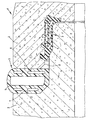
Dabei ist in der Zeichnung der lediglich ausschnittsweise dargestellte
Verbindungsbereich einer Rohrleitung 1 dargestellt, wobei
zwei Rohrleitungsabschnitte 2 teilweise dargestellt sind sowie
zwei Zusatzbauteile 3 in Form einer umlaufenden Dichtung
4 sowie in Form eines ebenfalls umlaufenden Fugenverschlussprofils
5.It is only partially shown in the drawing
Connection region of a
In an sich bekannter Weise bildet der rechts dargestellte Rohrleitungsabschnitt
2 ein Muffenende aus, während der links dargestellte
Rohrleitungsabschnitt 2 ein mit dem Muffenende korrespondierendes
Spitzende bildet, welches in das Muffenende
eingeführt ist. In an sich bekannter Weise dient die Dichtung 4,
die im Muffenabschnitt verankert ist, zur flüssigkeitsdichten Abdichtung
der Rohrleitung 1 in diesem Verbindungsbereich.In known manner, the pipe section shown on the right forms
2 a socket end, while the left shown
Pipe section 2 a corresponding with the socket end
Spiky forms into the thimble end
is introduced. In known manner, the seal 4,
which is anchored in the sleeve portion, for liquid-tight sealing
the
Die Dichtung 4 ist aus fertigungstechnischen Gründen von der
äußersten Stirnfläche 6 des Muffenendes beabstandet und weiterhin
ist aus fertigungstechnischen Gründen ein Kontakt zwischen
einem so genannten Spiegel 7 des Spitzendes mit dieser
Stirnfläche 6 des Muffenendes nicht vorgesehen, so dass sich
eine etwa L-förmige Nut 8 ergibt, die mit einem ersten Abschnitt
radial zwischen der Stirnfläche 6 und dem Spiegel 7 verläuft,
und die mit einem koaxial verlaufenden zweiten Abschnitt, der
sich aufgrund des Durchmesserunterschiedes zwischen dem
Spitzende und dem Muffenende ergibt, bis zur Dichtung 4 verläuft.The seal 4 is for manufacturing reasons of the
spaced
Innerhalb der Nut 8 ist das Fugenverschlussprofil 5 vorgesehen.
Dieses wird vor der Verbindung der beiden Rohrleitungsabschnitte
2 auf das Spitzende des links dargestellten Rohrleitungsabschnittes
2 montiert und gegen den Spiegel 7 gepresst.
Bei dem dargestellten Ausführungsbeispiel ist eine nachträgliche
Montage des Fugenverschlussprofils 5 auf dem Spitzende
des zunächst hergestellten Rohrleitungsabschnittes 2 möglich.
Abweichend davon kann vorgesehen sein, das Fugenverschlussprofil
5 bereits während der Fertigung des Rohrleitungsabschnittes
2 anzubringen und - ähnlich wie dies bei der Dichtung
4 ersichtlich ist - in dem Spiegel 7 mittels entsprechender,
am Fugenverschlussprofil 5 vorgesehener Vorsprünge zu verankern.Within the
Während der Verbindung der beiden Rohrleitungsabschnitte 2
wird das Spitzende des einen in das Muffenende des korrespondierenden
anderen Rohrleitungsabschnittes 2 eingeführt.
Um eine optimale Wirkung der Dichtung 4 und ein vollständiges
Eindringen des Spitzendes in das Muffenende zu gewährleisten,
ist das Fugenverschlussprofil 5 nicht als Puffer ausgestaltet,
welcher die Beweglichkeit des Spitzendes in das Muffenende
hinein begrenzt. Vielmehr weist das Fugenverschlussprofil 5 eine
Vielzahl von Hohlräumen auf, so dass es angesichts der
Kräfte, die beim Einführen des einen in den anderen Rohrabschnitt
2 auftreten, vergleichsweise leicht verformbar ist. Diese
Verformbarkeit stellt sicher, dass das Fugenverschlussprofil 5
zuverlässig wurzeldicht sowohl dem Spiegel 7 als auch der
Stirnfläche 6 anliegt, so dass keine Spalten, Fugen oder dergleichen
verbleiben, die das Vordringen von Wurzeln bis zur
Dichtung 4 ermöglichen würden. During the connection of the two
Gegebenenfalls kann abweichend von der vorbeschriebenen
Ausgestaltung das Fugenverschlussprofil 5 auch bewusst als
Anschlag oder Puffer ausgestaltet sein, der die Bewegung der
beiden Rohrleitungsabschnitte 2 gegeneinander begrenzt, so
dass eine besonders feste Anlage sowohl der Stirnfläche 6 als
auch des Spiegels 7 an dem Fugenverschlussprofil 5 gewährleistet
werden kann und damit ein Einwurzeln besonders zuverlässig
ausgeschlossen werden kann.If necessary, may differ from the above
Design the
Nicht nur das Fugenverschlussprofil 5 kann mit wurzelhemmenden
Stoffen versehen sein, sondern auch das andere Zusatzbauteil
3 in Form der Dichtung 4, so dass eine mehrfache Sicherheit
gegen das Eindringen von Wurzeln in die Rohrleitung 1
gegeben ist.Not only the
In ökologisch vorteilhafter Weise kann das in der Rohrleitung
geführte Medium möglichst gering mit wurzelhemmenden Substanzen
belastet werden. Zusätzlich dazu, dass Substanzen mit
sehr geringer Auswaschrate verwendet werden, können in der
Dichtung 4 aufgrund der wurzelhemmenden Wirkungsweise des
Fugenverschlussprofils 5 schwächere oder geringer dosierte
wurzelhemmende Stoffe verwendet werden. Zudem kann bei der
Herstellung der Dichtung 4, welche extrudiert wird, vorgesehen
sein, dass die wurzelhemmenden Stoffe z. B. mittels einer in den
Elastomerstrom ragenden Düse lediglich an einer Stelle am Umfang
der Dichtung eingebracht werden, so dass sich eine über
den Dichtungsquerschnitt ungleichmäßige Verteilung der wurzelhemmenden
Stoffe ergibt. An der zum Medium gerichteten
Seite der Dichtung kann daher eine möglichst geringe Konzentration
der wurzelhemmenden Stoffe erzielt werden, während an
der zum Erdreich gerichteten Seite der Dichtung die Konzentration
der wurzelhemmenden Stoffe deutlich höher sein kann.In an ecologically advantageous way, this can be done in the pipeline
Guided medium as low as possible with root-inhibiting substances
be charged. In addition to having substances with
very low leachate can be used in the
Seal 4 due to the root-inhibiting action of the
Die beiden Rohrleitungsabschnitte können nicht nur längs hintereinander angeordnet sein, sondern auch winklig zueinander ausgerichtet sein, z. B. bei einer Y-förmigen Abzweigung oder bei einem T-förmigen Hausanschluss. Insbesondere bei einem T-förmigen Hausanschluss kann vorgesehen sein, die Rohrleitungsabschnitte in einem größeren zeitlichen Abstand herzustellen und z. B. eine Hausanschlussleitung aus Kunststoff mit einem Durchmesser von etwa 150 mm an einen erheblich älteren Beton-Rohrleitungsabschnitt mit einem erheblich größeren Durchmesser anzuschließen, indem zunächst eine entsprechende Bohrung in den Beton-Rohrleitungsabschnitt eingebracht wird.The two pipe sections can not only along one behind the other be arranged, but also at an angle to each other be aligned, z. B. at a Y-shaped branch or at a T-shaped house connection. Especially with a T-shaped house connection can be provided, the pipe sections produce at a greater time interval and Z. B. a house connection pipe made of plastic with a Diameter of about 150 mm to a much older Concrete pipe section with a considerably larger Diameter connect by first a corresponding Hole introduced into the concrete pipe section becomes.
Claims (19)
mit wenigstens zwei Rohrleitungsabschnitten, zwischen denen sich eine Nut erstreckt,
wobei innerhalb der Nut ein wurzelhemmend ausgestaltetes Zusatz-Bauteil angeordnet ist,
dadurch gekennzeichnet, dass das Zusatz-Bauteil (3) - wie eine Dichtung (4) oder wie ein Last- oder Druckübertragungselement - einkomponentig aus ein- und demselben Werkstoff besteht und mit einem gegen Auswaschungen weitgehend beständigen Zusatz versehen ist.Buried pipeline,
with at least two pipe sections between which a groove extends,
wherein a root-inhibiting designed additional component is disposed within the groove,
characterized in that the additional component (3) - as a seal (4) or as a load or pressure transmission element - one-component consists of one and the same material and is provided with a largely resistant to washout additive.
dadurch gekennzeichnet, dass ein Rohrleitungsabschnitt (2) im Wesentlichen aus Beton besteht.Pipe according to one of the preceding claims,
characterized in that a pipe section (2) consists essentially of concrete.
dadurch gekennzeichnet, dass das Zusatz-Bauteil (3) im Wesentlichen aus Kunststoff besteht.Pipe according to one of the preceding claims,
characterized in that the additional component (3) consists essentially of plastic.
dadurch gekennzeichnet, dass das Zusatz-Bauteil (3) im Wesentlichen aus einem Elastomer besteht.Pipe according to one of claims 1 to 6,
characterized in that the additional component (3) consists essentially of an elastomer.
dadurch gekennzeichnet, dass das Zusatz-Bauteil (3) im Wesentlichen aus Holz oder einem Holwerkstoff besteht.Pipe according to one of claims 1 to 6,
characterized in that the additional component (3) consists essentially of wood or a Holwerkstoff.
dadurch gekennzeichnet, dass zusätzlich zu einer innerhalb der Nut (8) vorgesehenen Dichtung (4) ein wurzelhemmendes Zusatz-Bauteil (3) angeordnet ist,
wobei das Zusatz-Bauteil (3) als ein äußeres Fugenverschlussprofil (5) ausgestaltet ist, welches innerhalb der Nut (8) auf der Seite der Dichtung (4) angeordnet ist, welche von dem in der Rohrleitung geführten Medium abgewandt ist.Pipe according to one of the preceding claims,
characterized in that in addition to a seal (4) provided inside the groove (8) a root-inhibiting additional component (3) is arranged,
wherein the additional component (3) is designed as an outer joint closure profile (5) which is arranged inside the groove (8) on the side of the seal (4) which faces away from the medium carried in the pipeline.
dadurch gekennzeichnet, dass zusätzlich zu einer innerhalb der Nut (8) vorgesehenen Dichtung (4) ein wurzelhemmendes Zusatz-Bauteil (3) angeordnet ist,
wobei das Zusatz-Bauteil (3) als ein inneres Fugenverschlussprofil ausgestaltet ist, welches innerhalb der Nut (8) auf der Seite der Dichtung (4) angeordnet ist, welche dem in der Rohrleitung geführten Medium zugewandt ist.Pipe according to one of the preceding claims,
characterized in that in addition to a seal (4) provided inside the groove (8) a root-inhibiting additional component (3) is arranged,
wherein the additional component (3) is designed as an inner joint closure profile, which is arranged inside the groove (8) on the side of the seal (4), which faces the medium guided in the pipeline.
dadurch gekennzeichnet, dass das Fugenverschlussprofil (5) die Nut (8) von ihrer Mündung bis zur Dichtung (4) vollständig ausfüllt.Pipe according to claim 8 or 9,
characterized in that the joint closure profile (5) completely fills the groove (8) from its mouth to the seal (4).
dadurch gekennzeichnet, dass das Fugenverschlussprofil (5) Hohlräume aufweist.Pipe according to one of Claims 8 to 10,
characterized in that the joint closure profile (5) has cavities.
dadurch gekennzeichnet, dass das Fugenverschlussprofil (5) als Hohlkammerprofil ausgestaltet ist.Pipe according to claim 11,
characterized in that the joint closure profile (5) is designed as a hollow chamber profile.
dadurch gekennzeichnet, dass das Fugenverschlussprofil (5) als Schaumkörper ausgestaltet ist.Pipe according to claim 11,
characterized in that the joint closure profile (5) is designed as a foam body.
dadurch gekennzeichnet, dass das Fugenverschlussprofil (5) an einem Spitzende des einen Rohrleitungsabschnitts (2) angeordnet ist.Pipe according to one of claims 8 to 13,
characterized in that the joint closure profile (5) is arranged on a spigot end of the one pipe section (2).
dadurch gekennzeichnet, dass das Fugenverschlussprofil (5) einem umlaufenden Vorsprung - wie einem sogenannten Spiegel (7) - des Rohrleitungsabschnitts (2) anliegt.Pipe according to claim 8 to 14,
characterized in that the joint closure profile (5) a circumferential projection - such as a so-called mirror (7) - of the pipe section (2) is applied.
dadurch gekennzeichnet, dass die beiden Rohrleitungsabschnitte winklig zueinander ausgerichtet sind - wie bei einer Y-förmigen Abzweigung oder bei einem T-förmigen Hausanschluss.Pipe according to one of the preceding claims,
characterized in that the two pipe sections are aligned at an angle to each other - as in a Y-shaped branch or in a T-shaped house connection.
dadurch gekennzeichnet, dass das Zusatz-Bauteil (3) als extrudiertes Profil ausgestaltet ist.Pipe according to one of the preceding claims,
characterized in that the additional component (3) is designed as an extruded profile.
dadurch gekennzeichnet, dass das Zusatz-Bauteil (3) als Formteil ausgestaltet ist.Pipe according to one of claims 1 to 16,
characterized in that the additional component (3) is designed as a molded part.
wobei das Bauteil als Zusatz-Bauteil (3) nach einem der vorhergehenden Ansprüche ausgestaltet ist.Ring-shaped pipe component - such as a seal (4), a load transfer ring, a pressure transmission ring or a joint sealing ring - for mounting in a joint between two pipe sections,
wherein the component is designed as an additional component (3) according to one of the preceding claims.
Applications Claiming Priority (2)
| Application Number | Priority Date | Filing Date | Title |
|---|---|---|---|
| DE102004026013 | 2004-05-27 | ||
| DE200410026013 DE102004026013B4 (en) | 2004-05-27 | 2004-05-27 | Drainable pipeline with root protection, and method for laying a pipeline |
Publications (1)
| Publication Number | Publication Date |
|---|---|
| EP1600568A1 true EP1600568A1 (en) | 2005-11-30 |
Family
ID=34936920
Family Applications (1)
| Application Number | Title | Priority Date | Filing Date |
|---|---|---|---|
| EP05011327A Withdrawn EP1600568A1 (en) | 2004-05-27 | 2005-05-25 | Ground laid pipeline with protection against plant roots |
Country Status (2)
| Country | Link |
|---|---|
| EP (1) | EP1600568A1 (en) |
| DE (1) | DE102004026013B4 (en) |
Citations (10)
| Publication number | Priority date | Publication date | Assignee | Title |
|---|---|---|---|---|
| DE1166565B (en) * | 1959-05-14 | 1964-03-26 | August Hautzel | Concrete prepress pipeline |
| DE2845308A1 (en) * | 1978-10-18 | 1980-04-24 | Battenfeld Maschfab | Plastics pipe coupling sleeve - has two collars into which an elastic annular seal with Y-cross=section is firmly fitted |
| JPS59223783A (en) * | 1983-06-03 | 1984-12-15 | Tokai Rubber Ind Ltd | Water stopping sealant |
| DE3506339A1 (en) * | 1985-01-14 | 1986-07-17 | Schneider Gmbh & Co, 5020 Frechen | Pipe connection |
| WO1989002050A1 (en) * | 1987-09-01 | 1989-03-09 | Battelle Memorial Institute | Root-repelling pipe joints |
| DE3907477A1 (en) * | 1989-03-08 | 1990-09-13 | Muecher Hermann Gmbh | Plug-in connection which is secured with respect to axial displacement and is intended for socket pipes |
| DE3926879A1 (en) * | 1989-08-16 | 1991-02-21 | Muecher Hermann Gmbh | Coupling seal for concrete drainage pipes - has inner elastomeric hose seal fitted in radial space between pipe ends and subjected to internal gas pressure |
| US5096206A (en) * | 1990-06-01 | 1992-03-17 | W. E. Hall Company | Pipe joint sealer |
| EP1008795A1 (en) * | 1998-12-07 | 2000-06-14 | Forsheda AB | A sealing device |
| JP2000213052A (en) * | 1999-01-20 | 2000-08-02 | Sekisui House Ltd | Root intrusion preventing method |
Family Cites Families (2)
| Publication number | Priority date | Publication date | Assignee | Title |
|---|---|---|---|---|
| DE3329100A1 (en) * | 1983-08-11 | 1985-02-28 | Oskar Dipl.-Ing. Innsbruck Hohenbruck | Method of protecting buried objects against damage due to plant roots |
| DE202004011702U1 (en) * | 2004-07-26 | 2004-10-21 | Dupre, Frank | Infrastructure Channel |
-
2004
- 2004-05-27 DE DE200410026013 patent/DE102004026013B4/en not_active Expired - Fee Related
-
2005
- 2005-05-25 EP EP05011327A patent/EP1600568A1/en not_active Withdrawn
Patent Citations (10)
| Publication number | Priority date | Publication date | Assignee | Title |
|---|---|---|---|---|
| DE1166565B (en) * | 1959-05-14 | 1964-03-26 | August Hautzel | Concrete prepress pipeline |
| DE2845308A1 (en) * | 1978-10-18 | 1980-04-24 | Battenfeld Maschfab | Plastics pipe coupling sleeve - has two collars into which an elastic annular seal with Y-cross=section is firmly fitted |
| JPS59223783A (en) * | 1983-06-03 | 1984-12-15 | Tokai Rubber Ind Ltd | Water stopping sealant |
| DE3506339A1 (en) * | 1985-01-14 | 1986-07-17 | Schneider Gmbh & Co, 5020 Frechen | Pipe connection |
| WO1989002050A1 (en) * | 1987-09-01 | 1989-03-09 | Battelle Memorial Institute | Root-repelling pipe joints |
| DE3907477A1 (en) * | 1989-03-08 | 1990-09-13 | Muecher Hermann Gmbh | Plug-in connection which is secured with respect to axial displacement and is intended for socket pipes |
| DE3926879A1 (en) * | 1989-08-16 | 1991-02-21 | Muecher Hermann Gmbh | Coupling seal for concrete drainage pipes - has inner elastomeric hose seal fitted in radial space between pipe ends and subjected to internal gas pressure |
| US5096206A (en) * | 1990-06-01 | 1992-03-17 | W. E. Hall Company | Pipe joint sealer |
| EP1008795A1 (en) * | 1998-12-07 | 2000-06-14 | Forsheda AB | A sealing device |
| JP2000213052A (en) * | 1999-01-20 | 2000-08-02 | Sekisui House Ltd | Root intrusion preventing method |
Non-Patent Citations (2)
| Title |
|---|
| PATENT ABSTRACTS OF JAPAN vol. 009, no. 091 (C - 277) 19 April 1985 (1985-04-19) * |
| PATENT ABSTRACTS OF JAPAN vol. 2000, no. 11 3 January 2001 (2001-01-03) * |
Also Published As
| Publication number | Publication date |
|---|---|
| DE102004026013B4 (en) | 2007-05-03 |
| DE102004026013A1 (en) | 2005-12-22 |
Similar Documents
| Publication | Publication Date | Title |
|---|---|---|
| EP2315544B1 (en) | Foam shower base element | |
| DE20310390U1 (en) | Connection seal with ratchet teeth | |
| DE102008021470A1 (en) | Elastomer insert for a branch pipe connection | |
| AT403391B (en) | METHOD FOR THE PRODUCTION OF SEALANT JOINTS OF HOUSE CONNECTION PIPES AND SIMILAR INFLOW PIPES IN WASTEWATER CHANNELS | |
| DE4422648C2 (en) | Sollriß joint rail | |
| EP1312848A1 (en) | Pipe coupling and method to achieve a pipe coupling | |
| DE102013101462B4 (en) | installation kit | |
| DE2855201A1 (en) | Glass fibre reinforced synthetic mouldings with grit surfaces - forming claddings and protective covers for concrete drain pipes | |
| EP1600568A1 (en) | Ground laid pipeline with protection against plant roots | |
| DE3404073A1 (en) | Method of making a concrete trench wall | |
| DE102014009063B4 (en) | Coupling part for a quick coupling for high pressure hydraulic lines | |
| DD252647A5 (en) | DEVICE FOR CONNECTING TUBES | |
| DE202012010724U1 (en) | Tiefbaurohrsystem with at least one concrete hollow body and end element for this purpose | |
| EP1012417B1 (en) | Compression tubing for producing water-impermeable or only slightly water-permeable, gastight and/or friction-locked building joints and process for manufacturing the same | |
| DE3926879A1 (en) | Coupling seal for concrete drainage pipes - has inner elastomeric hose seal fitted in radial space between pipe ends and subjected to internal gas pressure | |
| DE202019105911U1 (en) | Connection system | |
| EP3985296B1 (en) | Connection system | |
| EP3779259B1 (en) | Connector for connecting a plastic pipe to a mineral channel pipe | |
| DE10323589A1 (en) | Fire and noise insulating profile especially for pipelines has straight cross-section and is made from flexible intumescent sound- absorbing material | |
| DE3446494C2 (en) | ||
| DE19837032A1 (en) | Apparatus for cleaning pipelines for gas, drinking water etc. comprises movable 'pig' which has substantially spherical shape and is provided on its exterior with bristles or flexible plate profiles | |
| WO1989006731A1 (en) | Injection device for introducing fluids under pressure into cracked structures | |
| DE202007005696U1 (en) | Tubular component for the production of lines, shafts, fittings and the like. | |
| DE202012100542U1 (en) | Telescopic installation kit | |
| DE102018110463B4 (en) | End piece for arrangement on a lining pipe and sealing set for forming an inlet and an outlet in a sewage shaft when renovating a sewer |
Legal Events
| Date | Code | Title | Description |
|---|---|---|---|
| PUAI | Public reference made under article 153(3) epc to a published international application that has entered the european phase |
Free format text: ORIGINAL CODE: 0009012 |
|
| AK | Designated contracting states |
Kind code of ref document: A1 Designated state(s): AT BE BG CH CY CZ DE DK EE ES FI FR GB GR HU IE IS IT LI LT LU MC NL PL PT RO SE SI SK TR |
|
| AX | Request for extension of the european patent |
Extension state: AL BA HR LV MK YU |
|
| RTI1 | Title (correction) |
Free format text: GROUND LAIED PIPELINE WITH PROTECTION AGAINST PLANT ROOTS |
|
| STAA | Information on the status of an ep patent application or granted ep patent |
Free format text: STATUS: THE APPLICATION HAS BEEN WITHDRAWN |
|
| 18W | Application withdrawn |
Effective date: 20060516 |