EP1603008A1 - Portable power supply with computer port - Google Patents
Portable power supply with computer port Download PDFInfo
- Publication number
- EP1603008A1 EP1603008A1 EP05250575A EP05250575A EP1603008A1 EP 1603008 A1 EP1603008 A1 EP 1603008A1 EP 05250575 A EP05250575 A EP 05250575A EP 05250575 A EP05250575 A EP 05250575A EP 1603008 A1 EP1603008 A1 EP 1603008A1
- Authority
- EP
- European Patent Office
- Prior art keywords
- power
- power supply
- battery
- compartment
- electronic device
- Prior art date
- Legal status (The legal status is an assumption and is not a legal conclusion. Google has not performed a legal analysis and makes no representation as to the accuracy of the status listed.)
- Pending
Links
Images
Classifications
-
- H—ELECTRICITY
- H02—GENERATION; CONVERSION OR DISTRIBUTION OF ELECTRIC POWER
- H02J—CIRCUIT ARRANGEMENTS OR SYSTEMS FOR SUPPLYING OR DISTRIBUTING ELECTRIC POWER; SYSTEMS FOR STORING ELECTRIC ENERGY
- H02J7/00—Circuit arrangements for charging or depolarising batteries or for supplying loads from batteries
- H02J7/0042—Circuit arrangements for charging or depolarising batteries or for supplying loads from batteries characterised by the mechanical construction
-
- G—PHYSICS
- G06—COMPUTING; CALCULATING OR COUNTING
- G06F—ELECTRIC DIGITAL DATA PROCESSING
- G06F1/00—Details not covered by groups G06F3/00 - G06F13/00 and G06F21/00
- G06F1/16—Constructional details or arrangements
- G06F1/1613—Constructional details or arrangements for portable computers
- G06F1/1632—External expansion units, e.g. docking stations
-
- H—ELECTRICITY
- H02—GENERATION; CONVERSION OR DISTRIBUTION OF ELECTRIC POWER
- H02J—CIRCUIT ARRANGEMENTS OR SYSTEMS FOR SUPPLYING OR DISTRIBUTING ELECTRIC POWER; SYSTEMS FOR STORING ELECTRIC ENERGY
- H02J7/00—Circuit arrangements for charging or depolarising batteries or for supplying loads from batteries
- H02J7/34—Parallel operation in networks using both storage and other dc sources, e.g. providing buffering
- H02J7/342—The other DC source being a battery actively interacting with the first one, i.e. battery to battery charging
Definitions
- the present invention relates to power supplies and more particularly to a portable, rechargeable power supply having a computer port.
- a wide variety of electronic products e.g., cellular phones, PDAs (personal digital assistants), palmtops, MP3 players, etc.
- PDAs personal digital assistants
- palmtops e.g., Samsung Galaxy Tabs
- MP3 players e.g., Samsung Galaxy Tabs
- a rechargeable battery is provided in the product.
- the manufacturers have spent much time and money in developing a battery having a larger capacity while trying to decrease the energy consumption of the product.
- a charger is of no use if power of the product is consumed in an outdoor environment.
- the present invention provides a portable power supply comprising a housing including a first compartment and a second compartment disposed on a top of the first compartment; an electronic device disposed in the first compartment; a power supply assembly disposed in the second compartment; a power indicator disposed on a top of the second compartment for displaying remaining power of the power supply assembly; a charging socket disposed on the second compartment for electrically connecting to a charger via a first cord; a power socket disposed on the second compartment for connecting to and supplying power to the electronic device via a second cord; and a computer port disposed on the second compartment for connecting to an external device via a cable so as to communicate data between the electronic device and the external device.
- the power supply assembly comprises a rechargeable battery; a battery switching member adapted to activate by turning on a switch; a booster circuit adapted to increase voltage of power sent from the battery to a predetermined value for enabling the electronic device; a charging circuit electrically connected to the charging socket for obtaining an external AC power and converting AC into DC; a battery protecting circuit adapted to break the power supply assembly when current exceeds a predetermined maximum value; and a battery power sensing circuit adapted to sense remaining power of the battery in response to activating the battery switching member and send an indicator of the remaining power of the battery to the power indicator.
- FIGS. 1 to 3 there is shown a portable power supply constructed in accordance with a preferred embodiment of the invention.
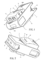
- the power supply is implemented as a substantially parallelepiped housing 1 including a main first compartment 11 having a first opening 13 at one end and a second opening 130 at the other end, a second compartment 12 formed on a top of the first compartment 11, and a clip 15 for hanging on the pocket or the belt while carrying the power supply.
- the power supply further comprises a power supply assembly 2, a power indicator 3, a charging socket 4, a power socket 5, and a computer port 6.
- a power supply assembly 2 a power indicator 3
- a charging socket 4 a power socket 5
- a computer port 6 Each component will be described in detailed below.
- a portable electronic device 9 (e.g., cellular phone or the like) is adapted to insert through the first opening 13 into the first compartment 11 for temporarily storage.
- the second compartment 12 is adapted to receive the power supply assembly 2.
- the power indicator 3 is provided on a top surface of the second compartment 12.
- a switch 220 is provided on a side of the second compartment 12.
- the charging socket 4 is provided adjacent the switch 220 at the same side.
- the charging socket 4 is implemented as a cylindrical receptacle having an axial prong the same as a typical power socket.
- the power socket 5 and the computer port 6 are provided on one end of the second compartment 12.
- the power supply assembly 2 For supplying power from the power supply assembly 2 to the consumed electronic device 9, connect one end of a power cord to the power socket 5 and the other end thereof to a charging socket (not shown) of the electronic device 9 via the second opening 130. Next, turn on the switch 220. The power supply assembly 2 starts to charge the electronic device 9 (i.e., rechargeable battery of the electronic device 9) immediately.
- the power socket 5 is implemented as an IEEE 1394 connector in the embodiment (see FIG. 1).
- a cable can be interconnected the computer port 6 and an external computer such that the electronic device 9 can communicate data with the computer.
- the computer port 6 is implemented as a USB (Universal Serial Bus) port in the embodiment (see FIG. 2).
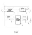
- the power supply assembly 2 comprises a rechargeable battery 21, a battery switching member 22, a DC/DC booster circuit 23, a charging circuit 24, a battery protecting circuit 25, and a battery power sensing circuit 26.
- the battery protecting circuit 25 is adapted to break the circuit when current exceeds a maximum value.
- the DC/DC booster circuit 23 is adapted to increase voltage to a predetermined value (e.g., 9V).
- the battery switching member 22 is activated by turning on the switch 220.
- the battery power sensing circuit 26 is adapted to sense remaining power of the battery 21 and send an indicator of the remaining power of the battery 21 to the power indicator 3.
- a first charging loop power is supplied from the battery 21 to the consumed electronic device 9 via the battery protecting circuit 25, the battery switching member 22, and the DC/DC booster circuit 23 after turning on the switch 220 (i.e., turning on the battery switching member 22).
- a second charging loop after turning on the switch 220 (i.e., turning on the battery switching member 22) when the battery 21 is low, external AC power is fed to the charging circuit 24 and is converted into DC which is then sent to the battery 21 via the battery switching member 22 and the battery protecting circuit 25.
- DC is fed from the charging circuit 24 to the DC/DC booster circuit 23 for changing its voltage to the predetermined value (e.g., 9V) prior to supplying to the consumed battery of the electronic device 9 directly.
- the predetermined value e.g. 9V
- the second charging loop, the third charging loop, or both of them can occur at the same time.
- the power indicator 3 comprises a plurality of illumination members (e.g., four LEDs (light-emitting diodes)) 31 served as a charge indicator of the battery 21.
- a user may turn on the switch 220 (i.e., turning on the battery switching member 22) to enable the battery power sensing circuit 26.
- none of the LEDs 31 are lit if the battery 21 is completely consumed, one, two, or three LEDS 31 are lit depending on the remaining power of the battery 21, or four LEDs 31 are lit if the battery 21 is completely charged. This enables a user to easily determine the remaining power of the battery 21.
Abstract
Description
- The present invention relates to power supplies and more particularly to a portable, rechargeable power supply having a computer port.
- A wide variety of electronic products (e.g., cellular phones, PDAs (personal digital assistants), palmtops, MP3 players, etc.) are available due to technological advancements. These products bring a lot of convenience to our daily life. Typically, a rechargeable battery is provided in the product. For prolonging the operating time of the product after a full charge, the manufacturers have spent much time and money in developing a battery having a larger capacity while trying to decrease the energy consumption of the product. It is understood that a charger is of no use if power of the product is consumed in an outdoor environment. Thus, it is desirable to provide a portable power supply for a portable electronic product and preferably, the power supply is provided with a computer port.
- It is an object of the present invention to provide a portable power supply having a first compartment for receiving an electronic device having a consumed battery and a second compartment for receiving a power supply assembly for charging the electronic device through a power cord for prolonging an operating time of the electronic device in an outdoor environment. Moreover, a charging of both the power supply assembly and the electronic device can be made by interconnecting a charging socket of the power supply assembly and an external power source via a cord.
- It is another object of the present invention to provide a portable power supply having a computer port such that the electronic device can communicate signals including video signals with an external computer via a cable interconnected the computer port and, for example, monitor of the computer.
- It is a further object of the present invention to provide a portable power supply having a power indicator disposed on the second compartment such that a user can easily determine the remaining power of a battery of the power supply assembly.
- To achieve the above and other objects, the present invention provides a portable power supply comprising a housing including a first compartment and a second compartment disposed on a top of the first compartment; an electronic device disposed in the first compartment; a power supply assembly disposed in the second compartment; a power indicator disposed on a top of the second compartment for displaying remaining power of the power supply assembly; a charging socket disposed on the second compartment for electrically connecting to a charger via a first cord; a power socket disposed on the second compartment for connecting to and supplying power to the electronic device via a second cord; and a computer port disposed on the second compartment for connecting to an external device via a cable so as to communicate data between the electronic device and the external device.
- In one aspect of the present invention the power supply assembly comprises a rechargeable battery; a battery switching member adapted to activate by turning on a switch; a booster circuit adapted to increase voltage of power sent from the battery to a predetermined value for enabling the electronic device; a charging circuit electrically connected to the charging socket for obtaining an external AC power and converting AC into DC; a battery protecting circuit adapted to break the power supply assembly when current exceeds a predetermined maximum value; and a battery power sensing circuit adapted to sense remaining power of the battery in response to activating the battery switching member and send an indicator of the remaining power of the battery to the power indicator.
- The above and other objects, features and advantages of the present invention will become apparent from the following detailed description taken with the accompanying drawings.
-
- FIG. 1 is a perspective view of a preferred embodiment of portable power supply according to the invention;
- FIG. 2 is another perspective view of the power supply with a portable electronic product mounted therein; and
- FIG. 3 is a block diagram of power supply assembly circuitry according to the invention.
-
- Referring to FIGS. 1 to 3, there is shown a portable power supply constructed in accordance with a preferred embodiment of the invention. The power supply is implemented as a substantially
parallelepiped housing 1 including a mainfirst compartment 11 having afirst opening 13 at one end and asecond opening 130 at the other end, asecond compartment 12 formed on a top of thefirst compartment 11, and aclip 15 for hanging on the pocket or the belt while carrying the power supply. The power supply further comprises apower supply assembly 2, apower indicator 3, acharging socket 4, apower socket 5, and acomputer port 6. Each component will be described in detailed below. - A portable electronic device 9 (e.g., cellular phone or the like) is adapted to insert through the
first opening 13 into thefirst compartment 11 for temporarily storage. Thesecond compartment 12 is adapted to receive thepower supply assembly 2. Thepower indicator 3 is provided on a top surface of thesecond compartment 12. Aswitch 220 is provided on a side of thesecond compartment 12. Thecharging socket 4 is provided adjacent theswitch 220 at the same side. Thecharging socket 4 is implemented as a cylindrical receptacle having an axial prong the same as a typical power socket. Thepower socket 5 and thecomputer port 6 are provided on one end of thesecond compartment 12. For charging the power supply (i.e., the power supply assembly 2), connect a charger (not shown) to a power outlet. Next, plug the end of a cord extended from the charger into thecharging socket 4. The power supply starts to charge immediately. - For supplying power from the
power supply assembly 2 to the consumedelectronic device 9, connect one end of a power cord to thepower socket 5 and the other end thereof to a charging socket (not shown) of theelectronic device 9 via thesecond opening 130. Next, turn on theswitch 220. Thepower supply assembly 2 starts to charge the electronic device 9 (i.e., rechargeable battery of the electronic device 9) immediately. Thepower socket 5 is implemented as an IEEE 1394 connector in the embodiment (see FIG. 1). - A cable can be interconnected the
computer port 6 and an external computer such that theelectronic device 9 can communicate data with the computer. Thecomputer port 6 is implemented as a USB (Universal Serial Bus) port in the embodiment (see FIG. 2). - Referring to FIG. 3, the
power supply assembly 2 comprises arechargeable battery 21, abattery switching member 22, a DC/DC booster circuit 23, acharging circuit 24, abattery protecting circuit 25, and a batterypower sensing circuit 26. Thebattery protecting circuit 25 is adapted to break the circuit when current exceeds a maximum value. The DC/DC booster circuit 23 is adapted to increase voltage to a predetermined value (e.g., 9V). Thebattery switching member 22 is activated by turning on theswitch 220. The batterypower sensing circuit 26 is adapted to sense remaining power of thebattery 21 and send an indicator of the remaining power of thebattery 21 to thepower indicator 3. In a first charging loop, power is supplied from thebattery 21 to the consumedelectronic device 9 via thebattery protecting circuit 25, thebattery switching member 22, and the DC/DC booster circuit 23 after turning on the switch 220 (i.e., turning on the battery switching member 22). In a second charging loop, after turning on the switch 220 (i.e., turning on the battery switching member 22) when thebattery 21 is low, external AC power is fed to thecharging circuit 24 and is converted into DC which is then sent to thebattery 21 via thebattery switching member 22 and thebattery protecting circuit 25. In a third charging loop after turning on the switch 220 (i.e., turning on the battery switching member 22), DC is fed from thecharging circuit 24 to the DC/DC booster circuit 23 for changing its voltage to the predetermined value (e.g., 9V) prior to supplying to the consumed battery of theelectronic device 9 directly. Note that the second charging loop, the third charging loop, or both of them can occur at the same time. - The
power indicator 3 comprises a plurality of illumination members (e.g., four LEDs (light-emitting diodes)) 31 served as a charge indicator of thebattery 21. A user may turn on the switch 220 (i.e., turning on the battery switching member 22) to enable the batterypower sensing circuit 26. Next, none of theLEDs 31 are lit if thebattery 21 is completely consumed, one, two, or threeLEDS 31 are lit depending on the remaining power of thebattery 21, or fourLEDs 31 are lit if thebattery 21 is completely charged. This enables a user to easily determine the remaining power of thebattery 21. - While the invention herein disclosed has been described by means of specific embodiments, numerous modifications and variations could be made thereto by those skilled in the art without departing from the scope and spirit of the invention set forth in the claims.
Claims (12)
- A portable power supply comprising:a housing including a first compartment and a second compartment disposed on a top of the first compartment;an electronic device disposed in the first compartment;a power supply assembly disposed in the second compartment;a power indicator disposed on a top of the second compartment for displaying remaining power of the power supply assembly;a charging socket disposed on the second compartment for electrically connecting to a charger via a first cord;a power socket disposed on the second compartment for connecting to and supplying power to the electronic device via a second cord; anda computer port disposed on the second compartment for connecting to an external device via a cable so as to communicate data between the electronic device and the external device.
- The power supply of claim 1, wherein the housing further comprises a first opening at one end in communication with the first compartment, a second opening at the other end in communication with the first compartment, and a switch disposed on the second compartment.
- The power supply of claim 2, wherein the power supply assembly comprises:a rechargeable battery;a battery switching member adapted to activate by turning on the switch;a booster circuit adapted to increase voltage of power sent from the battery to a predetermined value for enabling the electronic device;a charging circuit electrically connected to the charging socket for obtaining an external AC power and converting AC into DC;a battery protecting circuit adapted to break the power supply assembly when current exceeds a predetermined maximum value; anda battery power sensing circuit adapted to sense remaining power of the battery in response to activating the battery switching member and send an indicator of the remaining power of the battery to the power indicator.
- The power supply of claim 3, wherein in a first charging loop power is supplied from the battery to the consumed electronic device via the battery protecting circuit, the battery switching member, and the booster circuit responsive to turning on the switch.
- The power supply of claim 3, wherein in a second charging loop DC is sent from the charging circuit to the battery via the battery switching member and the battery protecting circuit responsive to turning on the switch.
- The power supply of claim 3, wherein in a third charging loop DC is sent from the charging circuit to the booster circuit for changing DC voltage to the predetermined value prior to supplying to the electronic device responsive to turning on the switch.
- The power supply of claim 3, wherein the power indicator is controlled by the battery switching member for displaying the remaining power of the battery.
- The power supply of claim 1, wherein the power indicator comprises a plurality of illumination members.
- The power supply of claim 3, wherein the charging socket is a cylindrical receptacle having an axial prong to electrically connect to an outer charger via a cord.
- The power supply of claim 1, characterized in that the power socket is an IEEE 1394 connector.
- The power supply of claim 1, characterized in that the computer port is a USB port.
- The power supply of claim 1, wherein the power socket supplying power to the electronic device via the second cord and the computer port connecting to an external device via a cable so as to communicate data between the electronic device and the external device.
Applications Claiming Priority (2)
| Application Number | Priority Date | Filing Date | Title |
|---|---|---|---|
| CN200410473389 | 2004-06-02 | ||
| CN200410473389 | 2004-06-02 |
Publications (1)
| Publication Number | Publication Date |
|---|---|
| EP1603008A1 true EP1603008A1 (en) | 2005-12-07 |
Family
ID=34940426
Family Applications (1)
| Application Number | Title | Priority Date | Filing Date |
|---|---|---|---|
| EP05250575A Pending EP1603008A1 (en) | 2004-06-02 | 2005-02-02 | Portable power supply with computer port |
Country Status (1)
| Country | Link |
|---|---|
| EP (1) | EP1603008A1 (en) |
Cited By (5)
| Publication number | Priority date | Publication date | Assignee | Title |
|---|---|---|---|---|
| WO2007108888A3 (en) * | 2006-03-21 | 2008-03-06 | Eveready Battery Inc | Direct current power supply |
| US7531986B2 (en) | 2006-02-23 | 2009-05-12 | Eveready Battery Company, Inc. | Power supply for battery powered devices |
| US8343670B2 (en) | 2007-01-25 | 2013-01-01 | Eveready Battery Company, Inc. | Use extender device |
| AU2011205191B2 (en) * | 2006-03-21 | 2014-08-28 | Energizer Brands, Llc | Direct Current Power Supply |
| US10485706B2 (en) | 2016-08-29 | 2019-11-26 | 3M Innovative Properties Company | Electronic hearing protector with switchable electrical contacts |
Citations (7)
| Publication number | Priority date | Publication date | Assignee | Title |
|---|---|---|---|---|
| US5497339A (en) * | 1993-11-15 | 1996-03-05 | Ete, Inc. | Portable apparatus for providing multiple integrated communication media |
| US5822546A (en) * | 1996-03-08 | 1998-10-13 | George; Stanley W. | Hand held docking station with deployable light source, rechargeable battery pack and recessed grip, for connecting to a palm top computer |
| US6049453A (en) * | 1997-12-09 | 2000-04-11 | Compaq Computer Corporation | Personal digital assistant and associated computer host device bay structure |
| US6087804A (en) * | 1998-06-26 | 2000-07-11 | Kabushiki Kaisha Toshiba | Electronic apparatus using the power supply line of a serial bus, for supplying and providing power appropriately |
| US20030052870A1 (en) * | 2001-09-14 | 2003-03-20 | Danielewicz Steven Robert | Method and apparatus for sharing an external power supply between a PDA and RF wireless modem |
| US20030178967A1 (en) * | 2002-03-21 | 2003-09-25 | Khatri Nizam Issa | Apparatus and method for the power management of operatively connected modular devices |
| WO2004038889A1 (en) * | 2002-10-26 | 2004-05-06 | Artrang Co., Ltd | External battery pack |
-
2005
- 2005-02-02 EP EP05250575A patent/EP1603008A1/en active Pending
Patent Citations (7)
| Publication number | Priority date | Publication date | Assignee | Title |
|---|---|---|---|---|
| US5497339A (en) * | 1993-11-15 | 1996-03-05 | Ete, Inc. | Portable apparatus for providing multiple integrated communication media |
| US5822546A (en) * | 1996-03-08 | 1998-10-13 | George; Stanley W. | Hand held docking station with deployable light source, rechargeable battery pack and recessed grip, for connecting to a palm top computer |
| US6049453A (en) * | 1997-12-09 | 2000-04-11 | Compaq Computer Corporation | Personal digital assistant and associated computer host device bay structure |
| US6087804A (en) * | 1998-06-26 | 2000-07-11 | Kabushiki Kaisha Toshiba | Electronic apparatus using the power supply line of a serial bus, for supplying and providing power appropriately |
| US20030052870A1 (en) * | 2001-09-14 | 2003-03-20 | Danielewicz Steven Robert | Method and apparatus for sharing an external power supply between a PDA and RF wireless modem |
| US20030178967A1 (en) * | 2002-03-21 | 2003-09-25 | Khatri Nizam Issa | Apparatus and method for the power management of operatively connected modular devices |
| WO2004038889A1 (en) * | 2002-10-26 | 2004-05-06 | Artrang Co., Ltd | External battery pack |
Cited By (12)
| Publication number | Priority date | Publication date | Assignee | Title |
|---|---|---|---|---|
| US7489105B2 (en) | 2005-03-21 | 2009-02-10 | Eveready Battery Company, Inc. | Portable power supply |
| US7777449B2 (en) | 2005-03-21 | 2010-08-17 | Eveready Battery Company, Inc. | Power supply that provides an output voltage through an electrical connector |
| US7531986B2 (en) | 2006-02-23 | 2009-05-12 | Eveready Battery Company, Inc. | Power supply for battery powered devices |
| US8022662B2 (en) | 2006-02-23 | 2011-09-20 | Eveready Battery Company, Inc. | Power supply for battery powered devices |
| US8686682B2 (en) | 2006-02-23 | 2014-04-01 | Eveready Battery Company, Inc. | Power supply for battery powered devices |
| WO2007108888A3 (en) * | 2006-03-21 | 2008-03-06 | Eveready Battery Inc | Direct current power supply |
| AU2007227729B2 (en) * | 2006-03-21 | 2011-05-12 | Energizer Brands, Llc | Direct current power supply |
| AU2011205191B2 (en) * | 2006-03-21 | 2014-08-28 | Energizer Brands, Llc | Direct Current Power Supply |
| US8343670B2 (en) | 2007-01-25 | 2013-01-01 | Eveready Battery Company, Inc. | Use extender device |
| US10485706B2 (en) | 2016-08-29 | 2019-11-26 | 3M Innovative Properties Company | Electronic hearing protector with switchable electrical contacts |
| US10987251B2 (en) | 2016-08-29 | 2021-04-27 | 3M Innovative Properties Company | Electronic hearing protector with switchable electrical contacts |
| US11337861B2 (en) | 2016-08-29 | 2022-05-24 | 3M Innovative Properties Company | Electronic hearing protector with switchable electrical contacts |
Similar Documents
| Publication | Publication Date | Title |
|---|---|---|
| US20050248312A1 (en) | Portable power supply with computer port | |
| US11355940B2 (en) | Multi-functional portable power charger | |
| US10148103B2 (en) | Multi-functional high capacity portable power charger | |
| EP3576247A1 (en) | Systems and methods for charging one or more electronic devices | |
| US10250056B2 (en) | Multi-function external attachment and safety circuit for a portable power charger | |
| US9705344B2 (en) | Video game controller charging system having a docking structure | |
| US20180316201A1 (en) | Portable power strip | |
| US20130193911A1 (en) | Motion-actuated portable charger | |
| US20130082543A1 (en) | Portable power supply | |
| US20070273327A1 (en) | Rechargeable battery assembly | |
| EP2578069A2 (en) | Power module for portable devices | |
| US20120212177A1 (en) | Electronic device back-up charger | |
| CN202586433U (en) | Mobile power supply | |
| GB2242794A (en) | Apparatus for charging two batteries according to a priority sequence | |
| EP1603008A1 (en) | Portable power supply with computer port | |
| US8248029B2 (en) | Multi-functional rechargeable charger and power supply with dual direct current outputs | |
| WO2009105113A1 (en) | External device charging while notebook is off | |
| US20060049695A1 (en) | Portable power supply with computer ports | |
| EP1643345A2 (en) | Portable power supply with computer ports | |
| CN202586434U (en) | Mobile power supply with Apple mobile phone protective casing | |
| US11689036B2 (en) | Free voltage adapter for charging | |
| CN211557313U (en) | Electronic equipment protective housing and electronic product assembly | |
| US8164219B2 (en) | Portable electronic device | |
| KR200389119Y1 (en) | Multipurpose portable power supply for mobile terminal using usb data communication cable | |
| CN115085308A (en) | Power supply and earphone |
Legal Events
| Date | Code | Title | Description |
|---|---|---|---|
| PUAI | Public reference made under article 153(3) epc to a published international application that has entered the european phase |
Free format text: ORIGINAL CODE: 0009012 |
|
| AK | Designated contracting states |
Kind code of ref document: A1 Designated state(s): AT BE BG CH CY CZ DE DK EE ES FI FR GB GR HU IE IS IT LI LT LU MC NL PL PT RO SE SI SK TR |
|
| AX | Request for extension of the european patent |
Extension state: AL BA HR LV MK YU |
|
| 17P | Request for examination filed |
Effective date: 20060605 |
|
| AKX | Designation fees paid |
Designated state(s): AT BE BG CH CY CZ DE DK EE ES FI FR GB GR HU IE IS IT LI LT LU MC NL PL PT RO SE SI SK TR |
|
| 17Q | First examination report despatched |
Effective date: 20060810 |
|
| STAA | Information on the status of an ep patent application or granted ep patent |
Free format text: STATUS: THE APPLICATION IS DEEMED TO BE WITHDRAWN |