EP1603169A2 - Photovoltaic module architecture - Google Patents
Photovoltaic module architecture Download PDFInfo
- Publication number
- EP1603169A2 EP1603169A2 EP05011402A EP05011402A EP1603169A2 EP 1603169 A2 EP1603169 A2 EP 1603169A2 EP 05011402 A EP05011402 A EP 05011402A EP 05011402 A EP05011402 A EP 05011402A EP 1603169 A2 EP1603169 A2 EP 1603169A2
- Authority
- EP
- European Patent Office
- Prior art keywords
- photovoltaic cell
- module
- electrode
- cathode
- interconnect
- Prior art date
- Legal status (The legal status is an assumption and is not a legal conclusion. Google has not performed a legal analysis and makes no representation as to the accuracy of the status listed.)
- Granted
Links
- 238000000034 method Methods 0.000 claims abstract description 68
- 239000000463 material Substances 0.000 claims description 201
- 239000000853 adhesive Substances 0.000 claims description 80
- 230000001070 adhesive effect Effects 0.000 claims description 80
- 239000000758 substrate Substances 0.000 claims description 63
- 229910052751 metal Inorganic materials 0.000 claims description 40
- 239000002184 metal Substances 0.000 claims description 40
- 239000000835 fiber Substances 0.000 claims description 29
- GWEVSGVZZGPLCZ-UHFFFAOYSA-N Titan oxide Chemical compound O=[Ti]=O GWEVSGVZZGPLCZ-UHFFFAOYSA-N 0.000 claims description 27
- 239000004020 conductor Substances 0.000 claims description 25
- 230000008569 process Effects 0.000 claims description 22
- 239000002245 particle Substances 0.000 claims description 9
- 238000010924 continuous production Methods 0.000 claims description 7
- 239000011324 bead Substances 0.000 claims description 4
- 229910000679 solder Inorganic materials 0.000 claims description 3
- 239000011149 active material Substances 0.000 claims description 2
- 239000011159 matrix material Substances 0.000 claims description 2
- 229920001169 thermoplastic Polymers 0.000 claims description 2
- 239000004416 thermosoftening plastic Substances 0.000 claims description 2
- 239000011810 insulating material Substances 0.000 claims 8
- 239000010410 layer Substances 0.000 description 177
- -1 for example Chemical compound 0.000 description 41
- 239000002800 charge carrier Substances 0.000 description 27
- 239000002105 nanoparticle Substances 0.000 description 27
- 239000000975 dye Substances 0.000 description 24
- 238000000576 coating method Methods 0.000 description 20
- 239000003795 chemical substances by application Substances 0.000 description 17
- 239000011248 coating agent Substances 0.000 description 17
- 239000004065 semiconductor Substances 0.000 description 17
- RTAQQCXQSZGOHL-UHFFFAOYSA-N Titanium Chemical compound [Ti] RTAQQCXQSZGOHL-UHFFFAOYSA-N 0.000 description 15
- 239000003054 catalyst Substances 0.000 description 15
- 229920000642 polymer Polymers 0.000 description 15
- 239000011888 foil Substances 0.000 description 14
- 229910052719 titanium Inorganic materials 0.000 description 13
- 239000010936 titanium Substances 0.000 description 13
- XLOMVQKBTHCTTD-UHFFFAOYSA-N Zinc monoxide Chemical compound [Zn]=O XLOMVQKBTHCTTD-UHFFFAOYSA-N 0.000 description 12
- 238000004519 manufacturing process Methods 0.000 description 12
- BASFCYQUMIYNBI-UHFFFAOYSA-N platinum Chemical compound [Pt] BASFCYQUMIYNBI-UHFFFAOYSA-N 0.000 description 12
- 229910045601 alloy Inorganic materials 0.000 description 11
- 239000000956 alloy Substances 0.000 description 11
- XMWRBQBLMFGWIX-UHFFFAOYSA-N C60 fullerene Chemical class C12=C3C(C4=C56)=C7C8=C5C5=C9C%10=C6C6=C4C1=C1C4=C6C6=C%10C%10=C9C9=C%11C5=C8C5=C8C7=C3C3=C7C2=C1C1=C2C4=C6C4=C%10C6=C9C9=C%11C5=C5C8=C3C3=C7C1=C1C2=C4C6=C2C9=C5C3=C12 XMWRBQBLMFGWIX-UHFFFAOYSA-N 0.000 description 10
- 239000003792 electrolyte Substances 0.000 description 7
- 229910003472 fullerene Inorganic materials 0.000 description 7
- 239000004973 liquid crystal related substance Substances 0.000 description 7
- 229910044991 metal oxide Inorganic materials 0.000 description 7
- 150000004706 metal oxides Chemical class 0.000 description 7
- XOLBLPGZBRYERU-UHFFFAOYSA-N tin dioxide Chemical compound O=[Sn]=O XOLBLPGZBRYERU-UHFFFAOYSA-N 0.000 description 7
- KDLHZDBZIXYQEI-UHFFFAOYSA-N Palladium Chemical compound [Pd] KDLHZDBZIXYQEI-UHFFFAOYSA-N 0.000 description 6
- 230000001788 irregular Effects 0.000 description 6
- HSZCZNFXUDYRKD-UHFFFAOYSA-M lithium iodide Chemical compound [Li+].[I-] HSZCZNFXUDYRKD-UHFFFAOYSA-M 0.000 description 6
- 229910052697 platinum Inorganic materials 0.000 description 6
- 239000002243 precursor Substances 0.000 description 6
- 239000011241 protective layer Substances 0.000 description 6
- 230000027756 respiratory electron transport chain Effects 0.000 description 6
- 239000011787 zinc oxide Substances 0.000 description 6
- 229920001940 conductive polymer Polymers 0.000 description 5
- 239000012777 electrically insulating material Substances 0.000 description 5
- 150000002739 metals Chemical class 0.000 description 5
- 239000002159 nanocrystal Substances 0.000 description 5
- 229920000123 polythiophene Polymers 0.000 description 5
- 230000001235 sensitizing effect Effects 0.000 description 5
- 239000007787 solid Substances 0.000 description 5
- 239000000243 solution Substances 0.000 description 5
- 239000002904 solvent Substances 0.000 description 5
- 229910001887 tin oxide Inorganic materials 0.000 description 5
- 238000012546 transfer Methods 0.000 description 5
- 229960001296 zinc oxide Drugs 0.000 description 5
- 229910001152 Bi alloy Inorganic materials 0.000 description 4
- RYGMFSIKBFXOCR-UHFFFAOYSA-N Copper Chemical compound [Cu] RYGMFSIKBFXOCR-UHFFFAOYSA-N 0.000 description 4
- PXHVJJICTQNCMI-UHFFFAOYSA-N Nickel Chemical compound [Ni] PXHVJJICTQNCMI-UHFFFAOYSA-N 0.000 description 4
- 239000002131 composite material Substances 0.000 description 4
- 239000002322 conducting polymer Substances 0.000 description 4
- 239000010949 copper Substances 0.000 description 4
- 229910052802 copper Inorganic materials 0.000 description 4
- 239000003431 cross linking reagent Substances 0.000 description 4
- 238000013461 design Methods 0.000 description 4
- 229920002313 fluoropolymer Polymers 0.000 description 4
- 238000007641 inkjet printing Methods 0.000 description 4
- 229920001778 nylon Polymers 0.000 description 4
- 230000003287 optical effect Effects 0.000 description 4
- 229920000301 poly(3-hexylthiophene-2,5-diyl) polymer Polymers 0.000 description 4
- 229920000767 polyaniline Polymers 0.000 description 4
- 238000013087 polymer photovoltaic Methods 0.000 description 4
- 229910001220 stainless steel Inorganic materials 0.000 description 4
- 239000004094 surface-active agent Substances 0.000 description 4
- 239000004753 textile Substances 0.000 description 4
- 230000032258 transport Effects 0.000 description 4
- 229920000742 Cotton Polymers 0.000 description 3
- 239000004593 Epoxy Substances 0.000 description 3
- 241000208202 Linaceae Species 0.000 description 3
- 235000004431 Linum usitatissimum Nutrition 0.000 description 3
- 150000001450 anions Chemical group 0.000 description 3
- 230000008901 benefit Effects 0.000 description 3
- 230000015572 biosynthetic process Effects 0.000 description 3
- UHYPYGJEEGLRJD-UHFFFAOYSA-N cadmium(2+);selenium(2-) Chemical compound [Se-2].[Cd+2] UHYPYGJEEGLRJD-UHFFFAOYSA-N 0.000 description 3
- 150000001875 compounds Chemical class 0.000 description 3
- 239000011521 glass Substances 0.000 description 3
- 238000007756 gravure coating Methods 0.000 description 3
- 229910052738 indium Inorganic materials 0.000 description 3
- APFVFJFRJDLVQX-UHFFFAOYSA-N indium atom Chemical compound [In] APFVFJFRJDLVQX-UHFFFAOYSA-N 0.000 description 3
- AMGQUBHHOARCQH-UHFFFAOYSA-N indium;oxotin Chemical compound [In].[Sn]=O AMGQUBHHOARCQH-UHFFFAOYSA-N 0.000 description 3
- 239000000203 mixture Substances 0.000 description 3
- 239000002073 nanorod Substances 0.000 description 3
- 229910052763 palladium Inorganic materials 0.000 description 3
- 229920003207 poly(ethylene-2,6-naphthalate) Polymers 0.000 description 3
- 229920003229 poly(methyl methacrylate) Polymers 0.000 description 3
- 229920000867 polyelectrolyte Polymers 0.000 description 3
- 229920000139 polyethylene terephthalate Polymers 0.000 description 3
- 229920001721 polyimide Polymers 0.000 description 3
- 239000004926 polymethyl methacrylate Substances 0.000 description 3
- 229920000128 polypyrrole Polymers 0.000 description 3
- 238000004528 spin coating Methods 0.000 description 3
- 239000010935 stainless steel Substances 0.000 description 3
- XLYOFNOQVPJJNP-UHFFFAOYSA-N water Substances O XLYOFNOQVPJJNP-UHFFFAOYSA-N 0.000 description 3
- 210000002268 wool Anatomy 0.000 description 3
- YEJRWHAVMIAJKC-UHFFFAOYSA-N 4-Butyrolactone Chemical compound O=C1CCCO1 YEJRWHAVMIAJKC-UHFFFAOYSA-N 0.000 description 2
- 229920003313 Bynel® Polymers 0.000 description 2
- VEXZGXHMUGYJMC-UHFFFAOYSA-M Chloride anion Chemical group [Cl-] VEXZGXHMUGYJMC-UHFFFAOYSA-M 0.000 description 2
- 239000004985 Discotic Liquid Crystal Substance Substances 0.000 description 2
- LFQSCWFLJHTTHZ-UHFFFAOYSA-N Ethanol Chemical compound CCO LFQSCWFLJHTTHZ-UHFFFAOYSA-N 0.000 description 2
- YLQBMQCUIZJEEH-UHFFFAOYSA-N Furan Chemical compound C=1C=COC=1 YLQBMQCUIZJEEH-UHFFFAOYSA-N 0.000 description 2
- 239000004831 Hot glue Substances 0.000 description 2
- GPXJNWSHGFTCBW-UHFFFAOYSA-N Indium phosphide Chemical compound [In]#P GPXJNWSHGFTCBW-UHFFFAOYSA-N 0.000 description 2
- LRHPLDYGYMQRHN-UHFFFAOYSA-N N-Butanol Chemical compound CCCCO LRHPLDYGYMQRHN-UHFFFAOYSA-N 0.000 description 2
- 229910019142 PO4 Inorganic materials 0.000 description 2
- 229910000978 Pb alloy Inorganic materials 0.000 description 2
- 206010034972 Photosensitivity reaction Diseases 0.000 description 2
- 229920003171 Poly (ethylene oxide) Polymers 0.000 description 2
- 229920001609 Poly(3,4-ethylenedioxythiophene) Polymers 0.000 description 2
- 239000004642 Polyimide Substances 0.000 description 2
- 229920000265 Polyparaphenylene Polymers 0.000 description 2
- VYPSYNLAJGMNEJ-UHFFFAOYSA-N Silicium dioxide Chemical compound O=[Si]=O VYPSYNLAJGMNEJ-UHFFFAOYSA-N 0.000 description 2
- BQCADISMDOOEFD-UHFFFAOYSA-N Silver Chemical compound [Ag] BQCADISMDOOEFD-UHFFFAOYSA-N 0.000 description 2
- 229910000831 Steel Inorganic materials 0.000 description 2
- 229910052771 Terbium Inorganic materials 0.000 description 2
- ZMZDMBWJUHKJPS-UHFFFAOYSA-M Thiocyanate anion Chemical group [S-]C#N ZMZDMBWJUHKJPS-UHFFFAOYSA-M 0.000 description 2
- YTPLMLYBLZKORZ-UHFFFAOYSA-N Thiophene Chemical group C=1C=CSC=1 YTPLMLYBLZKORZ-UHFFFAOYSA-N 0.000 description 2
- ATJFFYVFTNAWJD-UHFFFAOYSA-N Tin Chemical compound [Sn] ATJFFYVFTNAWJD-UHFFFAOYSA-N 0.000 description 2
- QCWXUUIWCKQGHC-UHFFFAOYSA-N Zirconium Chemical compound [Zr] QCWXUUIWCKQGHC-UHFFFAOYSA-N 0.000 description 2
- MCMNRKCIXSYSNV-UHFFFAOYSA-N Zirconium dioxide Chemical compound O=[Zr]=O MCMNRKCIXSYSNV-UHFFFAOYSA-N 0.000 description 2
- MCEWYIDBDVPMES-UHFFFAOYSA-N [60]pcbm Chemical compound C123C(C4=C5C6=C7C8=C9C%10=C%11C%12=C%13C%14=C%15C%16=C%17C%18=C(C=%19C=%20C%18=C%18C%16=C%13C%13=C%11C9=C9C7=C(C=%20C9=C%13%18)C(C7=%19)=C96)C6=C%11C%17=C%15C%13=C%15C%14=C%12C%12=C%10C%10=C85)=C9C7=C6C2=C%11C%13=C2C%15=C%12C%10=C4C23C1(CCCC(=O)OC)C1=CC=CC=C1 MCEWYIDBDVPMES-UHFFFAOYSA-N 0.000 description 2
- KHZAWAWPXXNLGB-UHFFFAOYSA-N [Bi].[Pb].[Sn] Chemical compound [Bi].[Pb].[Sn] KHZAWAWPXXNLGB-UHFFFAOYSA-N 0.000 description 2
- 239000002253 acid Substances 0.000 description 2
- 150000001252 acrylic acid derivatives Chemical class 0.000 description 2
- 239000012790 adhesive layer Substances 0.000 description 2
- 150000001336 alkenes Chemical class 0.000 description 2
- 125000000217 alkyl group Chemical group 0.000 description 2
- 229910052782 aluminium Inorganic materials 0.000 description 2
- XAGFODPZIPBFFR-UHFFFAOYSA-N aluminium Chemical compound [Al] XAGFODPZIPBFFR-UHFFFAOYSA-N 0.000 description 2
- 125000003118 aryl group Chemical group 0.000 description 2
- QVGXLLKOCUKJST-UHFFFAOYSA-N atomic oxygen Chemical compound [O] QVGXLLKOCUKJST-UHFFFAOYSA-N 0.000 description 2
- JWVAUCBYEDDGAD-UHFFFAOYSA-N bismuth tin Chemical compound [Sn].[Bi] JWVAUCBYEDDGAD-UHFFFAOYSA-N 0.000 description 2
- 230000000903 blocking effect Effects 0.000 description 2
- GDTBXPJZTBHREO-UHFFFAOYSA-N bromine Chemical compound BrBr GDTBXPJZTBHREO-UHFFFAOYSA-N 0.000 description 2
- 238000003486 chemical etching Methods 0.000 description 2
- MVPPADPHJFYWMZ-UHFFFAOYSA-N chlorobenzene Chemical compound ClC1=CC=CC=C1 MVPPADPHJFYWMZ-UHFFFAOYSA-N 0.000 description 2
- 229920000547 conjugated polymer Polymers 0.000 description 2
- 239000000356 contaminant Substances 0.000 description 2
- 229920001577 copolymer Polymers 0.000 description 2
- 230000007423 decrease Effects 0.000 description 2
- 229910003460 diamond Inorganic materials 0.000 description 2
- 239000010432 diamond Substances 0.000 description 2
- 230000000694 effects Effects 0.000 description 2
- 230000005684 electric field Effects 0.000 description 2
- 230000005611 electricity Effects 0.000 description 2
- 230000005284 excitation Effects 0.000 description 2
- 239000010408 film Substances 0.000 description 2
- 239000004811 fluoropolymer Substances 0.000 description 2
- 239000003574 free electron Substances 0.000 description 2
- 239000011245 gel electrolyte Substances 0.000 description 2
- PCHJSUWPFVWCPO-UHFFFAOYSA-N gold Chemical compound [Au] PCHJSUWPFVWCPO-UHFFFAOYSA-N 0.000 description 2
- 229910052737 gold Inorganic materials 0.000 description 2
- 239000010931 gold Substances 0.000 description 2
- 238000010438 heat treatment Methods 0.000 description 2
- ZMZDMBWJUHKJPS-UHFFFAOYSA-N hydrogen thiocyanate Chemical group SC#N ZMZDMBWJUHKJPS-UHFFFAOYSA-N 0.000 description 2
- 238000005304 joining Methods 0.000 description 2
- 229910052746 lanthanum Inorganic materials 0.000 description 2
- FZLIPJUXYLNCLC-UHFFFAOYSA-N lanthanum atom Chemical compound [La] FZLIPJUXYLNCLC-UHFFFAOYSA-N 0.000 description 2
- XCAUINMIESBTBL-UHFFFAOYSA-N lead(ii) sulfide Chemical compound [Pb]=S XCAUINMIESBTBL-UHFFFAOYSA-N 0.000 description 2
- 238000011068 loading method Methods 0.000 description 2
- 125000004108 n-butyl group Chemical group [H]C([H])([H])C([H])([H])C([H])([H])C([H])([H])* 0.000 description 2
- 229910052759 nickel Inorganic materials 0.000 description 2
- 229910052758 niobium Inorganic materials 0.000 description 2
- 239000010955 niobium Substances 0.000 description 2
- GUCVJGMIXFAOAE-UHFFFAOYSA-N niobium atom Chemical compound [Nb] GUCVJGMIXFAOAE-UHFFFAOYSA-N 0.000 description 2
- ZKATWMILCYLAPD-UHFFFAOYSA-N niobium pentoxide Chemical compound O=[Nb](=O)O[Nb](=O)=O ZKATWMILCYLAPD-UHFFFAOYSA-N 0.000 description 2
- 229910052757 nitrogen Inorganic materials 0.000 description 2
- 125000004433 nitrogen atom Chemical group N* 0.000 description 2
- QGLKJKCYBOYXKC-UHFFFAOYSA-N nonaoxidotritungsten Chemical compound O=[W]1(=O)O[W](=O)(=O)O[W](=O)(=O)O1 QGLKJKCYBOYXKC-UHFFFAOYSA-N 0.000 description 2
- 239000013307 optical fiber Substances 0.000 description 2
- 239000001301 oxygen Substances 0.000 description 2
- 229910052760 oxygen Inorganic materials 0.000 description 2
- VLTRZXGMWDSKGL-UHFFFAOYSA-M perchlorate Inorganic materials [O-]Cl(=O)(=O)=O VLTRZXGMWDSKGL-UHFFFAOYSA-M 0.000 description 2
- VLTRZXGMWDSKGL-UHFFFAOYSA-N perchloric acid Chemical group OCl(=O)(=O)=O VLTRZXGMWDSKGL-UHFFFAOYSA-N 0.000 description 2
- 235000021317 phosphate Nutrition 0.000 description 2
- 239000003504 photosensitizing agent Substances 0.000 description 2
- 239000004014 plasticizer Substances 0.000 description 2
- 229920000548 poly(silane) polymer Polymers 0.000 description 2
- 229920002239 polyacrylonitrile Polymers 0.000 description 2
- 238000002360 preparation method Methods 0.000 description 2
- 229910052709 silver Inorganic materials 0.000 description 2
- 239000004332 silver Substances 0.000 description 2
- 238000005245 sintering Methods 0.000 description 2
- JHJLBTNAGRQEKS-UHFFFAOYSA-M sodium bromide Chemical compound [Na+].[Br-] JHJLBTNAGRQEKS-UHFFFAOYSA-M 0.000 description 2
- 239000007784 solid electrolyte Substances 0.000 description 2
- 238000004544 sputter deposition Methods 0.000 description 2
- 239000010959 steel Substances 0.000 description 2
- 239000000126 substance Substances 0.000 description 2
- 229910052715 tantalum Inorganic materials 0.000 description 2
- GUVRBAGPIYLISA-UHFFFAOYSA-N tantalum atom Chemical compound [Ta] GUVRBAGPIYLISA-UHFFFAOYSA-N 0.000 description 2
- GZCRRIHWUXGPOV-UHFFFAOYSA-N terbium atom Chemical compound [Tb] GZCRRIHWUXGPOV-UHFFFAOYSA-N 0.000 description 2
- 229910052718 tin Inorganic materials 0.000 description 2
- 229910001174 tin-lead alloy Inorganic materials 0.000 description 2
- OGIDPMRJRNCKJF-UHFFFAOYSA-N titanium oxide Inorganic materials [Ti]=O OGIDPMRJRNCKJF-UHFFFAOYSA-N 0.000 description 2
- 239000012780 transparent material Substances 0.000 description 2
- ITMCEJHCFYSIIV-UHFFFAOYSA-N triflic acid Chemical group OS(=O)(=O)C(F)(F)F ITMCEJHCFYSIIV-UHFFFAOYSA-N 0.000 description 2
- WFKWXMTUELFFGS-UHFFFAOYSA-N tungsten Chemical compound [W] WFKWXMTUELFFGS-UHFFFAOYSA-N 0.000 description 2
- 229910052721 tungsten Inorganic materials 0.000 description 2
- 239000010937 tungsten Substances 0.000 description 2
- 229910001930 tungsten oxide Inorganic materials 0.000 description 2
- ZNOKGRXACCSDPY-UHFFFAOYSA-N tungsten(VI) oxide Inorganic materials O=[W](=O)=O ZNOKGRXACCSDPY-UHFFFAOYSA-N 0.000 description 2
- 150000003673 urethanes Chemical class 0.000 description 2
- 238000001429 visible spectrum Methods 0.000 description 2
- 229910052726 zirconium Inorganic materials 0.000 description 2
- VZRXIAGWZWMHMI-YTSWDMLESA-N (2s)-2-amino-5-[[(2r)-1-(carboxymethylamino)-1-oxo-3-[(1e)-1,2,3,4,4-pentachlorobuta-1,3-dienyl]sulfanylpropan-2-yl]amino]-5-oxopentanoic acid Chemical compound OC(=O)[C@@H](N)CCC(=O)N[C@H](C(=O)NCC(O)=O)CS\C(Cl)=C(/Cl)C(Cl)=C(Cl)Cl VZRXIAGWZWMHMI-YTSWDMLESA-N 0.000 description 1
- CHEANNSDVJOIBS-MHZLTWQESA-N (3s)-3-cyclopropyl-3-[3-[[3-(5,5-dimethylcyclopenten-1-yl)-4-(2-fluoro-5-methoxyphenyl)phenyl]methoxy]phenyl]propanoic acid Chemical compound COC1=CC=C(F)C(C=2C(=CC(COC=3C=C(C=CC=3)[C@@H](CC(O)=O)C3CC3)=CC=2)C=2C(CCC=2)(C)C)=C1 CHEANNSDVJOIBS-MHZLTWQESA-N 0.000 description 1
- QGKMIGUHVLGJBR-UHFFFAOYSA-M (4z)-1-(3-methylbutyl)-4-[[1-(3-methylbutyl)quinolin-1-ium-4-yl]methylidene]quinoline;iodide Chemical compound [I-].C12=CC=CC=C2N(CCC(C)C)C=CC1=CC1=CC=[N+](CCC(C)C)C2=CC=CC=C12 QGKMIGUHVLGJBR-UHFFFAOYSA-M 0.000 description 1
- JBOIAZWJIACNJF-UHFFFAOYSA-N 1h-imidazole;hydroiodide Chemical class [I-].[NH2+]1C=CN=C1 JBOIAZWJIACNJF-UHFFFAOYSA-N 0.000 description 1
- VMISXESAJBVFNH-UHFFFAOYSA-N 2-(4-carboxypyridin-2-yl)pyridine-4-carboxylic acid;ruthenium(2+);diisothiocyanate Chemical compound [Ru+2].[N-]=C=S.[N-]=C=S.OC(=O)C1=CC=NC(C=2N=CC=C(C=2)C(O)=O)=C1.OC(=O)C1=CC=NC(C=2N=CC=C(C=2)C(O)=O)=C1 VMISXESAJBVFNH-UHFFFAOYSA-N 0.000 description 1
- CHMILGIDWWDNMF-UHFFFAOYSA-N 3-(4-octylphenyl)thiophene Chemical compound C1=CC(CCCCCCCC)=CC=C1C1=CSC=C1 CHMILGIDWWDNMF-UHFFFAOYSA-N 0.000 description 1
- 229910000619 316 stainless steel Inorganic materials 0.000 description 1
- MARUHZGHZWCEQU-UHFFFAOYSA-N 5-phenyl-2h-tetrazole Chemical compound C1=CC=CC=C1C1=NNN=N1 MARUHZGHZWCEQU-UHFFFAOYSA-N 0.000 description 1
- ZCYVEMRRCGMTRW-UHFFFAOYSA-N 7553-56-2 Chemical compound [I] ZCYVEMRRCGMTRW-UHFFFAOYSA-N 0.000 description 1
- QTBSBXVTEAMEQO-UHFFFAOYSA-M Acetate Chemical compound CC([O-])=O QTBSBXVTEAMEQO-UHFFFAOYSA-M 0.000 description 1
- 229920002972 Acrylic fiber Polymers 0.000 description 1
- 229910001316 Ag alloy Inorganic materials 0.000 description 1
- 229910001020 Au alloy Inorganic materials 0.000 description 1
- CPELXLSAUQHCOX-UHFFFAOYSA-M Bromide Chemical group [Br-] CPELXLSAUQHCOX-UHFFFAOYSA-M 0.000 description 1
- 229910002971 CaTiO3 Inorganic materials 0.000 description 1
- OYPRJOBELJOOCE-UHFFFAOYSA-N Calcium Chemical compound [Ca] OYPRJOBELJOOCE-UHFFFAOYSA-N 0.000 description 1
- 229910052684 Cerium Inorganic materials 0.000 description 1
- 229910000881 Cu alloy Inorganic materials 0.000 description 1
- 229910000530 Gallium indium arsenide Inorganic materials 0.000 description 1
- 229920000271 Kevlar® Polymers 0.000 description 1
- WHXSMMKQMYFTQS-UHFFFAOYSA-N Lithium Chemical group [Li] WHXSMMKQMYFTQS-UHFFFAOYSA-N 0.000 description 1
- FYYHWMGAXLPEAU-UHFFFAOYSA-N Magnesium Chemical compound [Mg] FYYHWMGAXLPEAU-UHFFFAOYSA-N 0.000 description 1
- 229910016287 MxOy Inorganic materials 0.000 description 1
- 229910000990 Ni alloy Inorganic materials 0.000 description 1
- 239000004677 Nylon Substances 0.000 description 1
- 229910001252 Pd alloy Inorganic materials 0.000 description 1
- 239000004952 Polyamide Substances 0.000 description 1
- 239000004698 Polyethylene Substances 0.000 description 1
- 239000004743 Polypropylene Substances 0.000 description 1
- 229910001260 Pt alloy Inorganic materials 0.000 description 1
- JUJWROOIHBZHMG-UHFFFAOYSA-N Pyridine Chemical class C1=CC=NC=C1 JUJWROOIHBZHMG-UHFFFAOYSA-N 0.000 description 1
- 229910002370 SrTiO3 Inorganic materials 0.000 description 1
- 229910001069 Ti alloy Inorganic materials 0.000 description 1
- 229910003077 Ti−O Inorganic materials 0.000 description 1
- HCHKCACWOHOZIP-UHFFFAOYSA-N Zinc Chemical group [Zn] HCHKCACWOHOZIP-UHFFFAOYSA-N 0.000 description 1
- 238000002679 ablation Methods 0.000 description 1
- 238000004026 adhesive bonding Methods 0.000 description 1
- 150000004703 alkoxides Chemical class 0.000 description 1
- 229910021417 amorphous silicon Inorganic materials 0.000 description 1
- 235000010208 anthocyanin Nutrition 0.000 description 1
- 125000005577 anthracene group Chemical group 0.000 description 1
- 150000004982 aromatic amines Chemical class 0.000 description 1
- 239000012298 atmosphere Substances 0.000 description 1
- 229910052788 barium Inorganic materials 0.000 description 1
- DSAJWYNOEDNPEQ-UHFFFAOYSA-N barium atom Chemical group [Ba] DSAJWYNOEDNPEQ-UHFFFAOYSA-N 0.000 description 1
- 239000011230 binding agent Substances 0.000 description 1
- 239000001045 blue dye Substances 0.000 description 1
- 229910052794 bromium Inorganic materials 0.000 description 1
- YHWCPXVTRSHPNY-UHFFFAOYSA-N butan-1-olate;titanium(4+) Chemical compound [Ti+4].CCCC[O-].CCCC[O-].CCCC[O-].CCCC[O-] YHWCPXVTRSHPNY-UHFFFAOYSA-N 0.000 description 1
- 229930188620 butyrolactone Natural products 0.000 description 1
- AQCDIIAORKRFCD-UHFFFAOYSA-N cadmium selenide Chemical compound [Cd]=[Se] AQCDIIAORKRFCD-UHFFFAOYSA-N 0.000 description 1
- FRLJSGOEGLARCA-UHFFFAOYSA-N cadmium sulfide Chemical class [S-2].[Cd+2] FRLJSGOEGLARCA-UHFFFAOYSA-N 0.000 description 1
- 229910052791 calcium Inorganic materials 0.000 description 1
- 239000011575 calcium Substances 0.000 description 1
- 150000001716 carbazoles Chemical class 0.000 description 1
- 150000004649 carbonic acid derivatives Chemical class 0.000 description 1
- 125000003178 carboxy group Chemical group [H]OC(*)=O 0.000 description 1
- ZMIGMASIKSOYAM-UHFFFAOYSA-N cerium Chemical compound [Ce][Ce][Ce][Ce][Ce][Ce][Ce][Ce][Ce][Ce][Ce][Ce][Ce][Ce][Ce][Ce][Ce][Ce][Ce][Ce][Ce][Ce][Ce][Ce][Ce][Ce][Ce][Ce][Ce][Ce][Ce][Ce][Ce][Ce][Ce][Ce][Ce][Ce] ZMIGMASIKSOYAM-UHFFFAOYSA-N 0.000 description 1
- OZECDDHOAMNMQI-UHFFFAOYSA-H cerium(3+);trisulfate Chemical compound [Ce+3].[Ce+3].[O-]S([O-])(=O)=O.[O-]S([O-])(=O)=O.[O-]S([O-])(=O)=O OZECDDHOAMNMQI-UHFFFAOYSA-H 0.000 description 1
- 230000008859 change Effects 0.000 description 1
- 238000006243 chemical reaction Methods 0.000 description 1
- 239000007795 chemical reaction product Substances 0.000 description 1
- 238000005253 cladding Methods 0.000 description 1
- 229910017052 cobalt Inorganic materials 0.000 description 1
- 239000010941 cobalt Substances 0.000 description 1
- GUTLYIVDDKVIGB-UHFFFAOYSA-N cobalt atom Chemical compound [Co] GUTLYIVDDKVIGB-UHFFFAOYSA-N 0.000 description 1
- 238000004891 communication Methods 0.000 description 1
- 230000000536 complexating effect Effects 0.000 description 1
- 230000021615 conjugation Effects 0.000 description 1
- 238000010276 construction Methods 0.000 description 1
- 238000007796 conventional method Methods 0.000 description 1
- HVMJUDPAXRRVQO-UHFFFAOYSA-N copper indium Chemical compound [Cu].[In] HVMJUDPAXRRVQO-UHFFFAOYSA-N 0.000 description 1
- LCUOIYYHNRBAFS-UHFFFAOYSA-N copper;sulfanylideneindium Chemical compound [Cu].[In]=S LCUOIYYHNRBAFS-UHFFFAOYSA-N 0.000 description 1
- 238000005260 corrosion Methods 0.000 description 1
- 230000007797 corrosion Effects 0.000 description 1
- 238000004132 cross linking Methods 0.000 description 1
- 150000004292 cyclic ethers Chemical class 0.000 description 1
- DHCWLIOIJZJFJE-UHFFFAOYSA-L dichlororuthenium Chemical compound Cl[Ru]Cl DHCWLIOIJZJFJE-UHFFFAOYSA-L 0.000 description 1
- 238000003618 dip coating Methods 0.000 description 1
- 239000006185 dispersion Substances 0.000 description 1
- 238000001035 drying Methods 0.000 description 1
- 238000010292 electrical insulation Methods 0.000 description 1
- 238000004070 electrodeposition Methods 0.000 description 1
- 239000008151 electrolyte solution Substances 0.000 description 1
- 238000004049 embossing Methods 0.000 description 1
- YQGOJNYOYNNSMM-UHFFFAOYSA-N eosin Chemical compound [Na+].OC(=O)C1=CC=CC=C1C1=C2C=C(Br)C(=O)C(Br)=C2OC2=C(Br)C(O)=C(Br)C=C21 YQGOJNYOYNNSMM-UHFFFAOYSA-N 0.000 description 1
- 238000001704 evaporation Methods 0.000 description 1
- 230000008020 evaporation Effects 0.000 description 1
- 229920005570 flexible polymer Polymers 0.000 description 1
- 230000009477 glass transition Effects 0.000 description 1
- 238000007646 gravure printing Methods 0.000 description 1
- 239000001046 green dye Substances 0.000 description 1
- XMBWDFGMSWQBCA-UHFFFAOYSA-N hydrogen iodide Chemical compound I XMBWDFGMSWQBCA-UHFFFAOYSA-N 0.000 description 1
- 238000005286 illumination Methods 0.000 description 1
- 229910001505 inorganic iodide Inorganic materials 0.000 description 1
- 150000004694 iodide salts Chemical group 0.000 description 1
- PNDPGZBMCMUPRI-UHFFFAOYSA-N iodine Chemical compound II PNDPGZBMCMUPRI-UHFFFAOYSA-N 0.000 description 1
- 229910052740 iodine Inorganic materials 0.000 description 1
- 239000011630 iodine Substances 0.000 description 1
- 239000004761 kevlar Substances 0.000 description 1
- 238000002372 labelling Methods 0.000 description 1
- 238000003475 lamination Methods 0.000 description 1
- 229910052747 lanthanoid Inorganic materials 0.000 description 1
- 150000002602 lanthanoids Chemical class 0.000 description 1
- MRELNEQAGSRDBK-UHFFFAOYSA-N lanthanum oxide Inorganic materials [O-2].[O-2].[O-2].[La+3].[La+3] MRELNEQAGSRDBK-UHFFFAOYSA-N 0.000 description 1
- 238000000608 laser ablation Methods 0.000 description 1
- 125000005647 linker group Chemical group 0.000 description 1
- 239000011244 liquid electrolyte Substances 0.000 description 1
- 229910052744 lithium Inorganic materials 0.000 description 1
- 229910003002 lithium salt Inorganic materials 0.000 description 1
- 159000000002 lithium salts Chemical class 0.000 description 1
- 238000001459 lithography Methods 0.000 description 1
- 229910052749 magnesium Inorganic materials 0.000 description 1
- 239000011777 magnesium Substances 0.000 description 1
- DZVCFNFOPIZQKX-LTHRDKTGSA-M merocyanine Chemical compound [Na+].O=C1N(CCCC)C(=O)N(CCCC)C(=O)C1=C\C=C\C=C/1N(CCCS([O-])(=O)=O)C2=CC=CC=C2O\1 DZVCFNFOPIZQKX-LTHRDKTGSA-M 0.000 description 1
- 229910001507 metal halide Inorganic materials 0.000 description 1
- 150000005309 metal halides Chemical class 0.000 description 1
- 238000001465 metallisation Methods 0.000 description 1
- VNWKTOKETHGBQD-UHFFFAOYSA-N methane Chemical compound C VNWKTOKETHGBQD-UHFFFAOYSA-N 0.000 description 1
- 238000002156 mixing Methods 0.000 description 1
- CQDGTJPVBWZJAZ-UHFFFAOYSA-N monoethyl carbonate Chemical compound CCOC(O)=O CQDGTJPVBWZJAZ-UHFFFAOYSA-N 0.000 description 1
- 239000011234 nano-particulate material Substances 0.000 description 1
- 239000001048 orange dye Substances 0.000 description 1
- 125000002524 organometallic group Chemical group 0.000 description 1
- 150000004866 oxadiazoles Chemical class 0.000 description 1
- AHHWIHXENZJRFG-UHFFFAOYSA-N oxetane Chemical compound C1COC1 AHHWIHXENZJRFG-UHFFFAOYSA-N 0.000 description 1
- KTUFCUMIWABKDW-UHFFFAOYSA-N oxo(oxolanthaniooxy)lanthanum Chemical compound O=[La]O[La]=O KTUFCUMIWABKDW-UHFFFAOYSA-N 0.000 description 1
- 238000010422 painting Methods 0.000 description 1
- NBIIXXVUZAFLBC-UHFFFAOYSA-K phosphate Chemical compound [O-]P([O-])([O-])=O NBIIXXVUZAFLBC-UHFFFAOYSA-K 0.000 description 1
- 239000010452 phosphate Substances 0.000 description 1
- 150000003013 phosphoric acid derivatives Chemical class 0.000 description 1
- 229920003023 plastic Polymers 0.000 description 1
- 239000004033 plastic Substances 0.000 description 1
- 150000003058 platinum compounds Chemical class 0.000 description 1
- 229920003227 poly(N-vinyl carbazole) Polymers 0.000 description 1
- 229920000553 poly(phenylenevinylene) Polymers 0.000 description 1
- 229920003223 poly(pyromellitimide-1,4-diphenyl ether) Polymers 0.000 description 1
- 229920002647 polyamide Polymers 0.000 description 1
- 239000004417 polycarbonate Substances 0.000 description 1
- 229920000515 polycarbonate Polymers 0.000 description 1
- 229920000728 polyester Polymers 0.000 description 1
- 229920000570 polyether Polymers 0.000 description 1
- 229920000573 polyethylene Polymers 0.000 description 1
- 239000011112 polyethylene naphthalate Substances 0.000 description 1
- 229920005594 polymer fiber Polymers 0.000 description 1
- 229920000307 polymer substrate Polymers 0.000 description 1
- 150000008442 polyphenolic compounds Chemical class 0.000 description 1
- 235000013824 polyphenols Nutrition 0.000 description 1
- 229920001155 polypropylene Polymers 0.000 description 1
- 229920002635 polyurethane Polymers 0.000 description 1
- 239000004814 polyurethane Substances 0.000 description 1
- 150000004032 porphyrins Chemical class 0.000 description 1
- UKDIAJWKFXFVFG-UHFFFAOYSA-N potassium;oxido(dioxo)niobium Chemical compound [K+].[O-][Nb](=O)=O UKDIAJWKFXFVFG-UHFFFAOYSA-N 0.000 description 1
- 238000001556 precipitation Methods 0.000 description 1
- 150000003138 primary alcohols Chemical class 0.000 description 1
- 238000012545 processing Methods 0.000 description 1
- BDERNNFJNOPAEC-UHFFFAOYSA-N propan-1-ol Chemical compound CCCO BDERNNFJNOPAEC-UHFFFAOYSA-N 0.000 description 1
- RUOJZAUFBMNUDX-UHFFFAOYSA-N propylene carbonate Chemical compound CC1COC(=O)O1 RUOJZAUFBMNUDX-UHFFFAOYSA-N 0.000 description 1
- 239000001047 purple dye Substances 0.000 description 1
- 238000000197 pyrolysis Methods 0.000 description 1
- 239000001044 red dye Substances 0.000 description 1
- 238000006479 redox reaction Methods 0.000 description 1
- 230000009467 reduction Effects 0.000 description 1
- 238000007761 roller coating Methods 0.000 description 1
- QKQGVRDJJZYZDL-UHFFFAOYSA-N ruthenium(3+);triisothiocyanate Chemical compound S=C=N[Ru](N=C=S)N=C=S QKQGVRDJJZYZDL-UHFFFAOYSA-N 0.000 description 1
- 238000006748 scratching Methods 0.000 description 1
- 230000002393 scratching effect Effects 0.000 description 1
- 238000012216 screening Methods 0.000 description 1
- 150000003333 secondary alcohols Chemical class 0.000 description 1
- 150000003346 selenoethers Chemical class 0.000 description 1
- 238000000926 separation method Methods 0.000 description 1
- 238000009958 sewing Methods 0.000 description 1
- 238000007493 shaping process Methods 0.000 description 1
- 239000000377 silicon dioxide Substances 0.000 description 1
- GROMGGTZECPEKN-UHFFFAOYSA-N sodium metatitanate Chemical compound [Na+].[Na+].[O-][Ti](=O)O[Ti](=O)O[Ti]([O-])=O GROMGGTZECPEKN-UHFFFAOYSA-N 0.000 description 1
- 239000012703 sol-gel precursor Substances 0.000 description 1
- 241000894007 species Species 0.000 description 1
- 238000001228 spectrum Methods 0.000 description 1
- 238000009987 spinning Methods 0.000 description 1
- 238000005507 spraying Methods 0.000 description 1
- 230000006641 stabilisation Effects 0.000 description 1
- 238000011105 stabilization Methods 0.000 description 1
- 150000004763 sulfides Chemical class 0.000 description 1
- 239000013589 supplement Substances 0.000 description 1
- 229920001059 synthetic polymer Polymers 0.000 description 1
- 238000010345 tape casting Methods 0.000 description 1
- 150000004772 tellurides Chemical class 0.000 description 1
- 150000003509 tertiary alcohols Chemical class 0.000 description 1
- 239000010409 thin film Substances 0.000 description 1
- QHGNHLZPVBIIPX-UHFFFAOYSA-N tin(ii) oxide Chemical class [Sn]=O QHGNHLZPVBIIPX-UHFFFAOYSA-N 0.000 description 1
- 150000003608 titanium Chemical class 0.000 description 1
- ODHXBMXNKOYIBV-UHFFFAOYSA-N triphenylamine Chemical compound C1=CC=CC=C1N(C=1C=CC=CC=1)C1=CC=CC=C1 ODHXBMXNKOYIBV-UHFFFAOYSA-N 0.000 description 1
- 238000001771 vacuum deposition Methods 0.000 description 1
- 238000007740 vapor deposition Methods 0.000 description 1
- 229920002554 vinyl polymer Polymers 0.000 description 1
- 238000009941 weaving Methods 0.000 description 1
- 229910052725 zinc Inorganic materials 0.000 description 1
- 239000011701 zinc Chemical group 0.000 description 1
Images


Classifications
-
- H—ELECTRICITY
- H01—ELECTRIC ELEMENTS
- H01L—SEMICONDUCTOR DEVICES NOT COVERED BY CLASS H10
- H01L31/00—Semiconductor devices sensitive to infrared radiation, light, electromagnetic radiation of shorter wavelength or corpuscular radiation and specially adapted either for the conversion of the energy of such radiation into electrical energy or for the control of electrical energy by such radiation; Processes or apparatus specially adapted for the manufacture or treatment thereof or of parts thereof; Details thereof
- H01L31/04—Semiconductor devices sensitive to infrared radiation, light, electromagnetic radiation of shorter wavelength or corpuscular radiation and specially adapted either for the conversion of the energy of such radiation into electrical energy or for the control of electrical energy by such radiation; Processes or apparatus specially adapted for the manufacture or treatment thereof or of parts thereof; Details thereof adapted as photovoltaic [PV] conversion devices
- H01L31/042—PV modules or arrays of single PV cells
- H01L31/05—Electrical interconnection means between PV cells inside the PV module, e.g. series connection of PV cells
-
- H—ELECTRICITY
- H01—ELECTRIC ELEMENTS
- H01G—CAPACITORS; CAPACITORS, RECTIFIERS, DETECTORS, SWITCHING DEVICES OR LIGHT-SENSITIVE DEVICES, OF THE ELECTROLYTIC TYPE
- H01G9/00—Electrolytic capacitors, rectifiers, detectors, switching devices, light-sensitive or temperature-sensitive devices; Processes of their manufacture
- H01G9/20—Light-sensitive devices
- H01G9/2068—Panels or arrays of photoelectrochemical cells, e.g. photovoltaic modules based on photoelectrochemical cells
- H01G9/2081—Serial interconnection of cells
-
- H—ELECTRICITY
- H01—ELECTRIC ELEMENTS
- H01G—CAPACITORS; CAPACITORS, RECTIFIERS, DETECTORS, SWITCHING DEVICES OR LIGHT-SENSITIVE DEVICES, OF THE ELECTROLYTIC TYPE
- H01G9/00—Electrolytic capacitors, rectifiers, detectors, switching devices, light-sensitive or temperature-sensitive devices; Processes of their manufacture
- H01G9/20—Light-sensitive devices
- H01G9/2027—Light-sensitive devices comprising an oxide semiconductor electrode
- H01G9/2031—Light-sensitive devices comprising an oxide semiconductor electrode comprising titanium oxide, e.g. TiO2
-
- H—ELECTRICITY
- H01—ELECTRIC ELEMENTS
- H01G—CAPACITORS; CAPACITORS, RECTIFIERS, DETECTORS, SWITCHING DEVICES OR LIGHT-SENSITIVE DEVICES, OF THE ELECTROLYTIC TYPE
- H01G9/00—Electrolytic capacitors, rectifiers, detectors, switching devices, light-sensitive or temperature-sensitive devices; Processes of their manufacture
- H01G9/20—Light-sensitive devices
- H01G9/2059—Light-sensitive devices comprising an organic dye as the active light absorbing material, e.g. adsorbed on an electrode or dissolved in solution
- H01G9/2063—Light-sensitive devices comprising an organic dye as the active light absorbing material, e.g. adsorbed on an electrode or dissolved in solution comprising a mixture of two or more dyes
-
- H—ELECTRICITY
- H01—ELECTRIC ELEMENTS
- H01L—SEMICONDUCTOR DEVICES NOT COVERED BY CLASS H10
- H01L31/00—Semiconductor devices sensitive to infrared radiation, light, electromagnetic radiation of shorter wavelength or corpuscular radiation and specially adapted either for the conversion of the energy of such radiation into electrical energy or for the control of electrical energy by such radiation; Processes or apparatus specially adapted for the manufacture or treatment thereof or of parts thereof; Details thereof
- H01L31/04—Semiconductor devices sensitive to infrared radiation, light, electromagnetic radiation of shorter wavelength or corpuscular radiation and specially adapted either for the conversion of the energy of such radiation into electrical energy or for the control of electrical energy by such radiation; Processes or apparatus specially adapted for the manufacture or treatment thereof or of parts thereof; Details thereof adapted as photovoltaic [PV] conversion devices
- H01L31/042—PV modules or arrays of single PV cells
- H01L31/05—Electrical interconnection means between PV cells inside the PV module, e.g. series connection of PV cells
- H01L31/0504—Electrical interconnection means between PV cells inside the PV module, e.g. series connection of PV cells specially adapted for series or parallel connection of solar cells in a module
- H01L31/0512—Electrical interconnection means between PV cells inside the PV module, e.g. series connection of PV cells specially adapted for series or parallel connection of solar cells in a module made of a particular material or composition of materials
-
- H—ELECTRICITY
- H10—SEMICONDUCTOR DEVICES; ELECTRIC SOLID-STATE DEVICES NOT OTHERWISE PROVIDED FOR
- H10K—ORGANIC ELECTRIC SOLID-STATE DEVICES
- H10K39/00—Integrated devices, or assemblies of multiple devices, comprising at least one organic radiation-sensitive element covered by group H10K30/00
- H10K39/10—Organic photovoltaic [PV] modules; Arrays of single organic PV cells
-
- H—ELECTRICITY
- H10—SEMICONDUCTOR DEVICES; ELECTRIC SOLID-STATE DEVICES NOT OTHERWISE PROVIDED FOR
- H10K—ORGANIC ELECTRIC SOLID-STATE DEVICES
- H10K39/00—Integrated devices, or assemblies of multiple devices, comprising at least one organic radiation-sensitive element covered by group H10K30/00
- H10K39/601—Assemblies of multiple devices comprising at least one organic radiation-sensitive element
-
- H—ELECTRICITY
- H01—ELECTRIC ELEMENTS
- H01L—SEMICONDUCTOR DEVICES NOT COVERED BY CLASS H10
- H01L2924/00—Indexing scheme for arrangements or methods for connecting or disconnecting semiconductor or solid-state bodies as covered by H01L24/00
- H01L2924/0001—Technical content checked by a classifier
- H01L2924/0002—Not covered by any one of groups H01L24/00, H01L24/00 and H01L2224/00
-
- H—ELECTRICITY
- H10—SEMICONDUCTOR DEVICES; ELECTRIC SOLID-STATE DEVICES NOT OTHERWISE PROVIDED FOR
- H10K—ORGANIC ELECTRIC SOLID-STATE DEVICES
- H10K77/00—Constructional details of devices covered by this subclass and not covered by groups H10K10/80, H10K30/80, H10K50/80 or H10K59/80
- H10K77/10—Substrates, e.g. flexible substrates
- H10K77/111—Flexible substrates
-
- H—ELECTRICITY
- H10—SEMICONDUCTOR DEVICES; ELECTRIC SOLID-STATE DEVICES NOT OTHERWISE PROVIDED FOR
- H10K—ORGANIC ELECTRIC SOLID-STATE DEVICES
- H10K85/00—Organic materials used in the body or electrodes of devices covered by this subclass
- H10K85/30—Coordination compounds
- H10K85/341—Transition metal complexes, e.g. Ru(II)polypyridine complexes
- H10K85/344—Transition metal complexes, e.g. Ru(II)polypyridine complexes comprising ruthenium
-
- Y—GENERAL TAGGING OF NEW TECHNOLOGICAL DEVELOPMENTS; GENERAL TAGGING OF CROSS-SECTIONAL TECHNOLOGIES SPANNING OVER SEVERAL SECTIONS OF THE IPC; TECHNICAL SUBJECTS COVERED BY FORMER USPC CROSS-REFERENCE ART COLLECTIONS [XRACs] AND DIGESTS
- Y02—TECHNOLOGIES OR APPLICATIONS FOR MITIGATION OR ADAPTATION AGAINST CLIMATE CHANGE
- Y02E—REDUCTION OF GREENHOUSE GAS [GHG] EMISSIONS, RELATED TO ENERGY GENERATION, TRANSMISSION OR DISTRIBUTION
- Y02E10/00—Energy generation through renewable energy sources
- Y02E10/50—Photovoltaic [PV] energy
- Y02E10/542—Dye sensitized solar cells
-
- Y—GENERAL TAGGING OF NEW TECHNOLOGICAL DEVELOPMENTS; GENERAL TAGGING OF CROSS-SECTIONAL TECHNOLOGIES SPANNING OVER SEVERAL SECTIONS OF THE IPC; TECHNICAL SUBJECTS COVERED BY FORMER USPC CROSS-REFERENCE ART COLLECTIONS [XRACs] AND DIGESTS
- Y02—TECHNOLOGIES OR APPLICATIONS FOR MITIGATION OR ADAPTATION AGAINST CLIMATE CHANGE
- Y02E—REDUCTION OF GREENHOUSE GAS [GHG] EMISSIONS, RELATED TO ENERGY GENERATION, TRANSMISSION OR DISTRIBUTION
- Y02E10/00—Energy generation through renewable energy sources
- Y02E10/50—Photovoltaic [PV] energy
- Y02E10/549—Organic PV cells
-
- Y—GENERAL TAGGING OF NEW TECHNOLOGICAL DEVELOPMENTS; GENERAL TAGGING OF CROSS-SECTIONAL TECHNOLOGIES SPANNING OVER SEVERAL SECTIONS OF THE IPC; TECHNICAL SUBJECTS COVERED BY FORMER USPC CROSS-REFERENCE ART COLLECTIONS [XRACs] AND DIGESTS
- Y02—TECHNOLOGIES OR APPLICATIONS FOR MITIGATION OR ADAPTATION AGAINST CLIMATE CHANGE
- Y02P—CLIMATE CHANGE MITIGATION TECHNOLOGIES IN THE PRODUCTION OR PROCESSING OF GOODS
- Y02P70/00—Climate change mitigation technologies in the production process for final industrial or consumer products
- Y02P70/50—Manufacturing or production processes characterised by the final manufactured product
Definitions
- This description relates to photovoltaic modules, as well as related systems, methods and components.
- Photovoltaic cells can convert light, such as sunlight, into electrical energy.
- a typical photovoltaic cell includes a layer of a photoactive material and a layer of a charge carrier material disposed between a cathode and an anode. When incident light excites the photoactive material, electrons are released. The released electrons are captured in the form of electrical energy within the electric circuit created between the cathode and the anode.
- the photoactive material commonly called a dye-sensitized solar cell (DSSC)
- the photoactive material typically includes a semiconductor material, such as titania, and a photosensitizing agent, such as, for example, a dye.
- the dye is capable of absorbing photons within a wavelength range of operation (e.g., within the solar spectrum).
- the photoactive material used generally has two components, an electron acceptor and an electron donor.
- the electron acceptor can be a p-type polymeric conductor material, such as, for example poly(phenylene vinylene) or poly(3-hexylthiophene).
- the electron donor can be a nanoparticulate material, such as for example, a derivative of fullerene (e.g., 1-(3-methoxy carbonyl)-propyl-1-1-phenyl-(6,6) C 61 , known as PCBM).
- Photovoltaic cells can be electrically connected together in series and/or in parallel to create a photovoltaic module.
- two photovoltaic cells are connected in parallel by electrically connecting the cathode of one cell with the cathode of the other cell, and the anode of one cell with the anode of the other cell.
- two photovoltaic cells are connected in series by electrically connecting the anode of one cell with the cathode of the other cell.
- a module in one aspect, includes a first photovoltaic cell having an electrode and a second photovoltaic cell having an electrode.
- the module further includes an interconnect (e.g., an electrically conductive interconnect) that is disposed in the electrode of the first photovoltaic cell and the electrode of the second photovoltaic cell so that the electrode of the first photovoltaic cell and the electrode of the second photovoltaic cell are connected (e.g., electrically and/or mechanically connected).
- an interconnect e.g., an electrically conductive interconnect
- a module in another aspect, includes a first photovoltaic cell having an electrode and a second photovoltaic cell having an electrode.
- the module further includes an interconnect (e.g., an electrically conductive interconnect) that connects(e.g., electrically connects and/or mechanically connects) the electrode of the first photovoltaic cell and the electrode of the second photovoltaic cell.
- the photovoltaic cells are configured so that a portion of the electrode of the first photovoltaic cell overlaps a portion of the electrode of the second photovoltaic cell.
- a module in a further aspect, includes first and second photovoltaic cells.
- the first photovoltaic cell includes a cathode, an anode and a photoactive material between the cathode and the anode.
- the second photovoltaic cell includes a cathode, an anode and a photoactive material between the cathode and the anode.
- the module further includes an interconnect (e.g., an electrically conductive interconnect) that is disposed in the cathode of the first photovoltaic cell and the anode of the second photovoltaic cell so that the cathode of the first photovoltaic cell and the anode of the second photovoltaic cell are connected (e.g., electrically and/or mechanically connected).
- a module in an additional aspect, includes first and second photovoltaic cells.
- the first photovoltaic cell includes a cathode, an anode and a photoactive material between the cathode and the anode.
- the second photovoltaic cell includes a cathode, an anode and a photoactive material between the cathode and the anode.
- the module further includes an interconnect (e.g., an electrically conductive interconnect) that is disposed in the cathode of the first photovoltaic cell and the cathode of the second photovoltaic cell so that the cathode of the first photovoltaic cell and the cathode of the second photovoltaic cell are connected (e.g., electrically and/or mechanically connected).
- a module in another aspect, includes first and second photovoltaic cells.
- the first photovoltaic cell includes a cathode, an anode and a photoactive material between the cathode and the anode.
- the second photovoltaic cell includes a cathode, an anode and a photoactive material between the cathode and the anode.
- the module further includes an interconnect (e.g., an electrically conductive interconnect) that is disposed in the anode of the first photovoltaic cell and the anode of the second photovoltaic cell so that the anode of the first photovoltaic cell and the anode of the second photovoltaic cell are connected (e.g., electrically and/or mechanically connected).
- a module in a further aspect, includes first and second photovoltaic cells.
- the first photovoltaic cell includes a cathode, an anode and a photoactive material between the cathode and the anode.
- the second photovoltaic cell includes a cathode, an anode and a photoactive material between the cathode and the anode. A portion of the anode of the second photovoltaic cell overlaps a portion of the cathode of the first photovoltaic cell.
- the module also includes an interconnect (e.g., an electrically conductive interconnect) that connects (e.g., electrically connects and/or mechanically connects) the cathode of the first photovoltaic cell and the anode of the second photovoltaic cell.
- an interconnect e.g., an electrically conductive interconnect
- a module in an additional aspect, includes first and second photovoltaic cells.
- the first photovoltaic cell includes a cathode, an anode and a photoactive material between the cathode and the anode.
- the second photovoltaic cell includes a cathode, an anode and a photoactive material between the cathode and the anode. A portion of the anode of the second photovoltaic cell overlaps a portion of the cathode of the first photovoltaic cell.
- the module also includes an interconnect (e.g., an electrically conductive interconnect) that connects (e.g., electrically connects and/or mechanically connects) the cathode of the first photovoltaic cell and the cathode of the second photovoltaic cell.
- an interconnect e.g., an electrically conductive interconnect
- a module in another aspect, includes first and second photovoltaic cells.
- the first photovoltaic cell includes a cathode, an anode and a photoactive material between the cathode and the anode.
- the second photovoltaic cell includes a cathode, an anode and a photoactive material between the cathode and the anode. A portion of the anode of the second photovoltaic cell overlaps a portion of the cathode of the first photovoltaic cell.
- the module also includes an interconnect (e.g., an electrically conductive interconnect) that connects (e.g., electrically connects and/or mechanically connects) the anode of the first photovoltaic cell and the anode of the second photovoltaic cell.
- an interconnect e.g., an electrically conductive interconnect
- a module in a further aspect, includes first and photovoltaic cells, where the first and second photovoltaic cells are configured in a step-wise configuration.
- a method of electrically connecting photovoltaic cells includes disposing an interconnect (e.g., an electrically conductive interconnect) in an electrode of a first photovoltaic cell and in an electrode of a second photovoltaic cell to connect (e.g., electrically connect and/or mechanically connect) the electrode of the first photovoltaic cell and the electrode of the second photovoltaic cell.
- an interconnect e.g., an electrically conductive interconnect
- a module in one aspect, includes first and second photovoltaic cells.
- the module also includes an interconnect (e.g., an electrically conductive interconnect) that connects (e.g., electrically connects and/or mechanically connects) an electrode of the first photovoltaic cell and an electrode of the second photovoltaic cell.
- the interconnect includes an adhesive material and a mesh partially disposed in the adhesive material.
- a module in another aspect, includes first and second photovoltaic cells.
- the first and second photovoltaic cells each include a cathode, an anode and a photoactive material between the cathode and the anode.
- the module also includes an interconnect (e.g., an electrically conductive interconnect) that electrically connects (e.g., electrically connects and/or mechanically connects) an electrode of the first photovoltaic cell and an electrode of the second photovoltaic cell.
- the electrically connected electrodes can be cathode/anode, cathode/cathode or anode/anode.
- the interconnect includes an adhesive material and a mesh partially disposed in the adhesive material.
- a module in one aspect, includes a first photovoltaic cell including an electrode, and a second photovoltaic cell including an electrode having a bent end connected (e.g., electrically connected) to the electrode of the first photovoltaic cell.
- a module in another aspect, includes a first photovoltaic cell including an electrode, and a second photovoltaic cell including an electrode.
- the electrode in the second photovoltaic cell has a shaped (e.g., dimpled) or bent portion that is connected (e.g., electrically connected) to the electrode of the first photovoltaic cell.
- a module in one aspect, includes a first photovoltaic cell including an electrode, a second photovoltaic cell including an electrode, and an electrically conductive interconnect.
- the electrode of the first photovoltaic cell overlaps the electrode of the second photovoltaic cell.
- the interconnect electrically connects the electrode of the first photovoltaic cell and the electrode of the second photovoltaic cell.
- the interconnect mechanically couples the first and second photovoltaic cells.
- a module in another aspect, includes a first photovoltaic cell including an electrode, a second photovoltaic cell including an electrode, the second photovoltaic cell overlapping the first photovoltaic cell to define an overlapping region, and an interconnect adjacent the overlapping region to electrically and mechanically connect the first and second photovoltaic cells.
- a photovoltaic module in a further aspect, includes a first photovoltaic cell including an electrode with a first surface, a second photovoltaic cell including an electrode with a second surface, and an interconnect (e.g., an electrically conductive interconnect) that connects (e.g., electrically connects and/or mechanically connects) the first and second photovoltaic cells.
- the interconnect is supported by the first and second surfaces.
- a module in an additional aspect, includes first and second photovoltaic cells.
- the efficiency of the module is at least about 80% of the efficiency of one of the photovoltaic cells.
- a method includes making one or more of the preceding modules via a continuous process.
- a method includes making one or more of the preceding modules via a roll-to-roll process.
- Embodiments can provide one or more of the following advantages.
- the interconnects can connect (e.g., serially connect) two or more photovoltaic cells with little ohmic loss. This can be particularly desirable when trying to maximize voltage, amperage and/or power output from photovoltaic cells and modules.
- the interconnects can connect (e.g., serially connect) two or more photovoltaic cells together with little or no increase in fill-factor and little or no decrease in efficiency as compared to a single photovoltaic cell.
- the interconnects can mechanically connect adjacent photovoltaic cells together, thereby reducing (e.g., eliminating) the use seals (e.g., seals including) adhesives within photovoltaic modules.
- This can enhance the useful lifetime of a module by, for example, reducing the amount and/or presence of one or more materials that can be reactive with one or more of the components contained in a photovoltaic cell, and/or by, for example, reducing (e.g., eliminating) leak paths present in a module.
- the interconnects can provide a robust mechanical and/or highly electrically conductive connection between the cathode of the first photovoltaic cell and the anode of the second photovoltaic cell.
- the mesh in the interconnect can form multiple points of electrical contact with each electrode. Having multiple points of contact between the electrodes can increase the electrical conductivity between electrodes by providing a larger area and volume for electrical current to pass between electrodes via the interconnect. Alternatively or additionally, having multiple points of contact between the electrodes can enhance the stability of the flow of electrons between electrodes via the interconnect. For example, under certain circumstances, a module may be flexed or bent, which can temporarily or permanently break a point of contact between the interconnect and one of the electrodes. The resulting reduction in electrical conductivity between electrodes is reduced when multiple points of electrical contact are present.
- the mesh can be formed of relatively fine strands without substantial difficulty.
- the absolute height of the metal mesh can set the gap/space between the electrodes, and allow for this gap/space to be relatively small.
- the adhesive can enhance the mechanical integrity of the interconnect by, for example, providing multiple points of adhesive bonding between the electrodes in adjacent photovoltaic cells in the module.
- the adhesive can provide electrical insulation between certain components of the module that are not desired to be in electrical contact.
- the modules can provide good electrical contact between electrodes in adjacent photovoltaic cells without the presence of a separate interconnect to provide the electrical communication. This can reduce the cost and/or complexity associated with manufacture of the modules. For example, by forming the shaped (e.g., dimpled) portions of the cathode (and/or anode) during the process of manufacturing the module, the complexity of aligning various portions of the module can be reduced.
- an oxide film can form on the surface of the cathode during processing (e.g., sintering of the titania).
- the process of shaping the portions of the cathode can break the oxide film, which can enhance the electrical conductivity between the cathode and the anode.
- the potential surface area of the adhesive/substrate bond can be relatively high, which can enhance the bond strength and reliability of the photovoltaic cell.
- a module can include fewer components, which can enhance reliability and/or reduce cost.
- one or more of the materials that form an interconnect are commercially available in compositions that are substantially inert to other components of the module (e.g., the electrolyte(s)).
- a module can include flexible substrates of photovoltaic cells are electrically and mechanically connected to form a flexible module which is well suited for wide-ranging implementations.
- an interconnect can electrically and/or mechanically interconnect one or more photovoltaic cells (e.g., one or more adjacent photovoltaic cells) to formed a photovoltaic module having enhanced stability, enhanced reliability, reduced inactive area between photovoltaic cells (e.g., adjacent photovoltaic cells), and/or reduced inactive volume between photovoltaic cells (e.g., adjacent photovoltaic cells).
- the description relates to photovoltaic modules formed by electrically and/or mechanically connecting one or more photovoltaic cells (e.g., one or more adjacent photovoltaic cells) using one or more interconnects.
- photovoltaic cells e.g., one or more adjacent photovoltaic cells
- interconnects e.g., one or more interconnects
- the efficiency of a photovoltaic module can be at least about 80% (e.g., at least about 85%, at least about 90%, at least about 95%, at least about 98%) of the efficiency of one or more of the photovoltaic cells contained in the photovoltaic module.
- the efficiency of a photovoltaic cell is measured as follows.
- the photovoltaic cell is exposed to an A.M. 1.5 (100 mW per square cm) light source (Oriel Solar Simulator) for 30 seconds.
- the current generated within the photovoltaic cell is measured and plotted against voltage to determine the efficiency of the photovoltaic cell.
- the efficiency of a photovoltaic module is measured as follows.
- the photovoltaic module is exposed to an A.M. 1.5 (100 mW per square cm) light source (Oriel Solar Simulator) for 30 seconds.
- the current generated within the photovoltaic module is measured and plotted against voltage to determine the efficiency of the photovoltaic module.
- FIG. 1 shows a cross-sectional view of a photovoltaic module 100 that includes an electrically conductive interconnect 105 that connects a first photovoltaic cell 110 to a second photovoltaic cell 115.
- the electrically conductive interconnect 105 can include a stitch, in one example.
- Photovoltaic cell 110 includes a cathode 120, a photoactive layer 122, a charge carrier layer 124, an anode 126, and a substrate 128.
- photovoltaic cell 115 includes a cathode 140, a photoactive layer 142, a charge carrier layer 144, an anode 146, and a substrate 148.
- Photovoltaic cells 110 and 115 are positioned with respect to each other in a step-wise configuration, such that a portion 155 of photovoltaic cell 110 overlaps a portion 160 of photovoltaic cell 115, thereby forming an overlapping region 165.
- An electrically conductive interconnect 105 is disposed within overlapping region 165 to provide an electrically conductive path from cathode 120 to anode 146.
- electrically conductive interconnect 105 is sized to create an electrically conductive and continuous path from cathode 120 to anode 146.
- electrically conductive interconnect 105 is sized to extend through cathode 120, substrate 148 and anode 146 within overlapping region 165.
- electrically conductive interconnect 105 has a length of at least about 30 microns and/or at most about 500 microns (e.g., a length of from about 100 microns to about 200 microns).
- the width of electrically conductive interconnect 105 can be selected as desired. In some embodiments, the width of electrically conductive interconnect 105 is selected so that the width of overlapping region 165 is relatively small. For example, in certain embodiments, the width of electrically conductive interconnect 105 is less than about 1500 microns (e.g., less than about 1000 microns, less than about 500 microns). Typically, electrically conductive interconnect 105 is at least about 100 microns wide. Reducing the width of the overlapping region 165 can be particularly desirable when trying to increase the available photoactive area within photovoltaic cells 110 and 115. For example, as the width of overlapping region 165 decreases, the area of the active region of module 100 increases.
- electrically conductive interconnect 105 can be made from any electrically conductive material.
- an electrically conductive material has a conductivity of at least about 10 ( ⁇ -cm) -1 at 25°C.
- the material(s) used to form electrically conductive interconnect 105 is relatively strong so as to secure photovoltaic cell 110 to photovoltaic cell 115.
- Exemplary materials for forming electrically conductive interconnects 105 include, for example, metals, such as, copper and titanium, and alloys, such as, steel, tin-lead alloys, tin-bismuth alloys, lead-bismuth alloys, tin-bismuth-lead alloys.
- electrically conductive interconnect 105 can be formed of a material (e.g., a polymer fiber, such a nylon fiber, a polyester fiber, a Kevlar fiber, an Orlon fiber) that is coated with a metal or an alloy.
- electrically conductive interconnect 105 is formed of a metal or an alloy coated with a low temperature solder, such as, for example, a tin-lead alloy, a tin-bismuth alloy, a lead-bismuth alloy, or a tin-bismuth-lead alloy.
- electrically conductive interconnect is formed of a metal or an alloy that is coated with an epoxy, such as, for example, a silver based epoxy.
- interconnects 200 which may be electrically conductive or electrically insulating, (e.g., electrically conductive and/or electrically insulating stitches) can be used to secure terminal contacts 205 (e.g., metal tapes, thin metal foils, and metal braids) to the electrodes at the ends of photovoltaic module 100 (e.g., at anode 126 and at cathode 140).
- Terminal contacts 205 are typically used as a connection site between photovoltaic modules and electric devices, so that the electricity generated within the photovoltaic module can be used to drive connected electric devices.
- interconnects 200 can be made from any desired material. Typically, interconnects 200 are made from a material that is strong enough to secure the terminal contact to the desired electrode. Exemplary materials used for forming interconnects 200 include those noted above with respect to electrically conductive interconnect 105, and polymers.
- a photovoltaic module 200 includes a first photovoltaic cell 180, a second photovoltaic cell 185 and a third photovoltaic cell 190.
- An electrically conductive interconnect 192 is used to join the cathode of photovoltaic cell 180 with the anode of photovoltaic cell 185, and a second electrically conductive interconnect 194 is used to join the cathode of photovoltaic cell 185 with the anode of photovoltaic cell 190.
- FIG. 4 shows a photovoltaic module 220 that includes photovoltaic cells 210, 212, and 214 that share a common substrate 290.
- Photovoltaic cells 210, 212, and 214 each include a photoactive layer 280 and a charge carrier layer 285 disposed between a cathode 270 and an anode 275.
- Regions 295 of electrically insulating material are positioned between cells 210 and 212 and between cells 212 and 214.
- a portion of cathode 270 of cell 210 overlaps a portion of anode 275 of cell 212 to form an overlapping region 265 within which electrically conductive interconnect 105 is positioned (in substrate 290, in anode 275 of cell 212, in region 295 between cells 210 and 212, in cathode 270 of cell 210, and in substrate 300).
- cathode 270 of cell 212 overlaps a portion of anode 275 of cell 214 to form an overlapping region 267 within which electrically conductive interconnect 105 is positioned (in substrate 290, in anode 275 of cell 214, in region 295 between cells 212 and 214, in cathode 270 of cell 212, and in substrate 300).
- FIG. 5 shows a module 300 that includes photovoltaic cells 310, 320 and 330 that share common substrates 340 and 345.
- Each photovoltaic cell includes cathode 350, a photoactive layer 360, a charge carrier layer 370 and an anode 380.
- interconnect 301 is formed of a mesh 305 and an electrically insulative material 390.
- Mesh 305 has electrically conductive regions 385 and open regions 387, and electrically insulative material 390 is disposed in open regions 387 of mesh 305.
- An upper surface 393 of mesh 305 contacts anode 380, and a lower surface 395 of mesh 305 contacts cathode 350.
- electrodes 350 and 380 in adjacent cells are electrically connected in the direction between electrodes 350 and 380 via regions 385 of mesh 305, while adjacent photovoltaic cells are electrically insulated from each other by adhesive material 397 in the perpendicular plane.
- mesh 305 can be prepared in various ways.
- mesh 305 is an expanded mesh.
- An expanded metal mesh can be prepared, for example, by removing regions 387 (e.g., via laser removal, via chemical etching, via puncturing) from a sheet of material (e.g., an electrically conductive material, such as a metal or an alloy), followed by stretching the sheet (e.g., stretching the sheet in two dimensions).
- mesh 305 is a metal sheet formed by removing regions 387 (e.g., via laser removal, via chemical etching, via puncturing) without subsequently stretching the sheet.
- mesh 305 is a woven mesh formed by weaving wires of material that form solid regions 385. The wires can be woven using, for example, a plain weave, a Dutch, weave, a twill weave, a Dutch twill weave, or combinations thereof
- mesh 305 is formed of a welded wire mesh.
- regions 385 are formed entirely of an electrically conductive material (e.g., regions 385 are formed of a substantially homogeneous material that is electrically conductive).
- electrically conductive materials that can be used in regions 385 include electrically conductive metals, electrically conductive alloys and electrically conductive polymers.
- Exemplary electrically conductive metals include gold, silver, copper, nickel, palladium, platinum and titanium.
- Exemplary electrically conductive alloys include stainless steel (e.g., 332-stainless steel, 316-stainless steel), alloys of gold, alloys of silver, alloys of copper, alloys of nickel, alloys of palladium, alloys of platinum and alloys of titanium.
- Exemplary electrically conducting polymers include polythiophenes (e.g., poly(3,4-ethelynedioxythiophene) (PEDOT)), polyanilines (e.g., doped polyanilines), polypyrroles (e.g., doped polypyrroles). In some embodiments, combinations of electrically conductive materials are used.
- PEDOT poly(3,4-ethelynedioxythiophene)
- PEDOT poly(3,4-ethelynedioxythiophene)
- polyanilines e.g., doped polyanilines
- polypyrroles e.g., doped polypyrroles.
- combinations of electrically conductive materials are used.
- solid regions 385 are formed of a material that is coated with a different material (e.g., using metallization, using vapor deposition).
- the inner material can be formed of any desired material (e.g., an electrically insulative material, an electrically conductive material, or a semiconductive material), and the outer material is an electrically conductive material.
- electrically insulative material from which the inner material can be formed include textiles, optical fiber materials, polymeric materials (e.g., a nylon) and natural materials (e.g., flax, cotton, wool, silk).
- electrically conductive materials from which the outer material can be formed include the electrically conductive materials disclosed above.
- the inner material is in the form of a fiber
- the outer material is an electrically conductive material that is coated on the inner material.
- the inner material is in the form of a mesh (see discussion above) that, after being formed into a mesh, is coated with the outer material.
- the inner material can be an expanded metal mesh
- the outer material can be PEDOT that is coated on the expanded metal mesh.
- the maximum thickness of mesh 305 in a direction substantially perpendicular to the surfaces of substrates 340 and 345 is at least 10 microns (e.g., at least about 15 microns, at least about 25 microns, at least about 50 microns) and/or at most about 250 microns (e.g., at most about 200 microns, at most about 150 microns, at most about 100 microns, at most about 75 microns).
- open regions 387 can generally have any desired shape (e.g., square, circle, semicircle, triangle, ellipse, trapezoid, irregular shape). In some embodiments, different open regions 387 in mesh 305 can have different shapes.
- solid regions 385 can generally form any desired design (e.g., rectangle, circle, semicircle, triangle, ellipse, trapezoid, irregular shape). In some embodiments, different solid regions 385 in mesh 305 can have different shapes.
- FIGs. 8A and 8B show a photovoltaic module 500 that includes photovoltaic cells 505, 510 and 515 that are positioned in a step-wise configuration with respect to each other.
- a portion 525 of photovoltaic cell 515 overlaps a portion 520 of photovoltaic cell 510.
- a portion 533 of photovoltaic cell 510 overlaps a portion 535 of photovoltaic cell 505.
- a cathode 540 of cell 505 is electrically connected to an anode 545 of adjacent cell 505 by wrapping the edge of the anode 545 with an electrically conductive tape 547.
- the tape 547 can be sized to contact the entire back face of the cathode 540 and thus provide a mechanical attachment between adjacent cells or only a portion of the cathode 540.
- the exposed portion of the back face of the cathode 540 can be optionally coated with a non-conductive adhesive to supplement the attachment to the anode 545 to the adjacent cell 505.
- element 547 has been described as a conductive tape, more generally, element 547 can be any kind of electrically conductive element having the general structure described. In some embodiments, elements 547 is in the form of a coating.
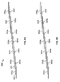
- FIG. 9A shows a photovoltaic module 550 that includes seven overlapping cells 555a-5552g arranged in step-wise configuration.
- Interconnect 560a is applied parallel to an edge of the cell 555a along the anode 565a for electrical and mechanical connection to the cathode 570 of adjacent cell 555b.
- interconnects 560b-560f connect overlapping cells 555b and 555c, 555c and 555d, 555d and 555e, 555e and 555f, and 555f and 555g.
- FIG 9B shows the interconnects 560 pressed into place to connect adjacent cells.
- interconnects 560 can be formed of any appropriate electrically conductive material.
- one or more interconnects 560 are formed of a bead of a conductive paste.
- one or more of the interconnects 560 can be formed with a thermoplastic conductive ribbon, solder and/or fiber.
- the material forming interconnect 560 is positioned parallel to the edge of one cell so that after applying the appropriate amount of heat and pressure, the interconnect is distributed over the cathode of one cell and the anode of an adjacent cell.
- One or more of interconnects 560a-560f can be formed by a process that does not involve the use of heat or pressure (e.g., ink jet printing, painting/drying).
- a thermal transfer process can be used to form one or more of interconnects 560a-560f.
- one or more of interconnects 560a-560f can be formed of a mesh (e.g., an adhesive mesh), as described herein.
- FIG. 10 shows a photovoltaic module 3100 that includes photovoltaic cells 3110, 3120, and 3130 that share common substrates 3140 and 3145.
- Each photovoltaic cell includes an adhesive 3147, a cathode 3150, a photoactive layer 3160, a charge carrier layer 3170, a anode 3180 and an adhesive 3190.
- Cathode 3150 includes a shaped (e.g., dimpled, embossed) portion 3152 configured to extend through adhesive 190 and make electrical contact with anode 3180.
- cathode 3150 has multiple shaped portions 3152 with non-shaped portions therebetween. With this arrangement, shaped portions 3152 of cathode 3150 form an electrical connection between cathode 3150 and anode 3180 without using a separate interconnect component.
- more generally shaped portions 3152 can have any desired shape (e.g., square, circle, semicircle, triangle, ellipse, trapezoid, corrugated, such as sinusoidally corrugated, irregular shape).
- cathodes 3150 are formed of a relatively thin, electrically conductive layer.
- cathodes 3150 are formed of a metal or an alloy (e.g., titanium or indium) foil.
- cathodes are formed of a relatively thin layer of a plastic (see discussion regarding substrates 3140 and 3145 below) that has a surface coated with an electrically conductive material (e.g., a metal or an alloy, such as titanium or indium).
- Shaped portions 3152 can be formed using a variety of techniques, including standard foil embossing techniques. For example, in certain embodiments, shaped portions 3152 can be formed by running foil 150 under a sewing machine with a blunted needle.
- shaped portions 3152 can be formed by passing foil 3150 over a spinning wheel having protrusions (e.g., dimples). Shaped portions 3152 can be formed in foil 3150 before being incorporated into module 3100, or shaped portions 3152 can be formed in foil 3150 as module 3100 is being manufactured (see discussion below).
- electrode 3150 is substantially flat, except for embossments 3152.
- embossments 3152 can generally have any desired shape, embossments 3152 typically have a slight radius (e.g., so that forming embossments 3152 does not result in the formation of holes in electrode 3150).
- FIGs. 12 and 13 show a partially exploded view of a photovoltaic module 8000 that includes photovoltaic cells 8100, 8200, 8300 and 8400.
- Each cell includes a cathode side 8010 and an anode side 8020.
- Each cathode side 8010 includes substrate 8012, an adhesive layer 8014 (e.g., a foil adhesive, such as a one mil thick foil adhesive), an electrically conductive layer 8016 (e.g., a metal layer, such as a two mils thick titanium foil) and a photoactive layer 8018 (e.g., a dye sensitized titania layer).
- Each anode side includes substrate 8020 and a catalyst layer 8022 (e.g., a platinum-containing catalyst layer).
- a region 8017 of each portion of layer 8016 is shaped (e.g., embossed, dimpled) and there is a gap 8019 between layers 8016 in adjacent photovoltaic cells.
- Module 8000 further includes an electrically conductive bridge 8026 that, after assembly of module 8000, is in direct contact with corresponding portion 8017 of corresponding layer 8016, thereby providing an electrical connection.
- Bridges 8026 are typically compliant and electrically conductive.
- bridges 8026 can be formed of a compliant polymer matrix containing electrically conductive particles (e.g., at sufficient loading to impart sufficient electrical conductivity to bridges 8026).
- one or more bridges 8026 can contain titanium (e.g., in the form of a titanium composite).
- bridges 8026 can be disposed directly on corresponding portions 8017 of corresponding layers 8016.
- a bridge 8026 can be printed onto a corresponding portion 8017 of corresponding layer 8016.
- Module 8000 also includes seals 8028 and 8029.
- Seals 8028 and 8029 reduce leaking of components (e.g., between adjacent cells) and/or reduce corrosion of components (e.g., if moisture gets into one or more cells).
- the upper and lower ends of seal 8029 contact layers 8014 and 8022, respectively, and the upper and lower ends of seal 8028 contacts layers 8026 and 8022, respectively.
- Seals 8028 and 8029 are generally formed of an adhesive material, such as those described herein, and may optionally containing one or more structural components (e.g., one more beads).
- the structural components are typically electrically nonconductive and/or at sufficiently low loading so that seals 8028 and/or 8029 are electrically nonconductive.
- Module 8000 further includes end seals 8030 and 8032 (e.g., adhesive end seals).
- modules having the general design illustrates in FIGs. 12 and 13 can allow for a relatively thin photovoltaic module, that still provides good electrical power and efficiency. It is believed that the use of multiple adhesive layers (e.g., seals 8028 and 8029) can provide an advantage in that construction of the module can be achieved without pushing a portion of a layer through an adhesive. This can also reduce the possibility of scratching one of the electrodes, which can result in a localized area of reduced electrical conductivity.
- multiple adhesive layers e.g., seals 8028 and 8029
- FIG. 14 shows a photovoltaic module 4000 in which cathode 3350 has a bent end 3352 configured to extend through adhesive 3190 and make electrical contact with anode 3180. As shown in FIG. 15, bent end 3352 forms a cathode forms a line. With this arrangement, bent end 3352 of cathode 3350 form an electrical connection between cathode 3350 and anode 3180 without using a separate interconnect component.
- bent end 3352 can be noncontinuous (e.g., when viewed as shown in FIG. 15, there can be alternating portions of cathode 3350 having a bent end).
- the cathodes have been described as being formed of a foil formed of certain materials, in some embodiments, one or more of the primary foils can be formed of a different material. In some embodiments, the cathodes can be formed of a foil of a transparent electrically conductive material, such as. Examples of such materials include certain metal oxides, such as indium tin oxide (ITO), tin oxide, a fluorine-doped tin oxide, and zinc-oxide.
- ITO indium tin oxide
- tin oxide tin oxide
- fluorine-doped tin oxide a fluorine-doped tin oxide
- zinc-oxide zinc-oxide
- the cathodes can be a discontinuous layer of an electrically conductive material, such as an electrically conducting mesh.
- Suitable mesh materials include metals, such as palladium, titanium, platinum, stainless steel and alloys thereof.
- the mesh material can include a metal wire.
- the electrically conductive mesh material can also include an electrically insulating material that has been coated with an electrically conductive material, such as metal.
- the electrically insulating material can include a fiber, such as a textile fiber or an optical fiber. Examples of textile fibers include synthetic polymer fibers (e.g., nylons) and natural fibers (e.g., flax, cotton, wool, and silk).
- the mesh electrode can be flexible to facilitate, for example, formation of a photovoltaic cell by a continuous manufacturing process.
- a mesh cathode can take a wide variety of forms with respect to, for example, wire (or fiber) diameters and mesh densities (i.e., the number of wire (or fiber) per unit area of the mesh).
- the mesh can be, for example, regular or irregular, with any number of opening shapes (e.g., square, circle, semicircle, triangular, diamond, ellipse, trapezoid, and/or irregular shapes).
- Mesh form factors can be chosen, for example, based on the electrical conductivity of the wire (or fibers) of the mesh, the desired optical transmissivity, based on the electrical conductivity of the wires (or fibers) of the mesh, the desired optical transmissivity, flexibility, and/or mechanical strength.
- the mesh electrode includes a wire (or fiber) mesh with an average wire (or fiber) diameter in the range from about 1 micron to about 400 microns, and an average open area between wires (or fibers) in the range from about 60% to about 95%.
- a mesh electrode can be formed using a variety of techniques, such as, for example, ink jet printing, lithography and/or ablation (e.g., laser ablation).
- a mesh electrode can be formed of an expanded metal mesh.
- Mesh electrodes are discussed in U.S. Patent Application Serial No. 10/395,823, filed March 23, 2003 and in U.S. Patent Application Serial No. 10/723,554, filed November 26, 2003.
- Adhesives 3147 and 3190 can generally be formed of any electrically insulative adhesive.
- adhesives include co-polymers of olefins, acrylates, and urethanes, and other hotmelt adhesives.
- commercially available adhesives include Bynel® adhesives (available from DuPont), thermobond adhesive 845 (available from 3M) and DyneonTM THV220 fluoropolymer adhesive (available from 3M).
- a photovoltaic cell is a DSSC.
- FIG. 16 is a cross-sectional view of a DSSC 4300 including substrates 4310 and 4370, electrically conductive layers (electrodes) 4320 and 4360, a catalyst layer 4330, a charge carrier layer 4340, and a photoactive layer 4350.
- Photoactive layer 4350 generally includes one or more dyes and a semiconductor material associated with the dye.
- dyes examples include black dyes (e.g., tris(isothiocyanato)-ruthenium (II)-2,2':6',2"-terpyridine-4,4',4"-tricarboxylic acid, tris-tetrabutylammonium salt), orange dyes (e.g., tris(2,2'-bipyridyl-4,4'-dicarboxylato) ruthenium (II) dichloride, purple dyes (e.g., cis-bis(isothiocyanato)bis-(2,2'-bipyridyl-4,4'-dicarboxylato)-ruthenium (II)), red dyes (e.g., an eosin), green dyes (e.g., a merocyanine) and blue dyes (e.g., a cyanine).
- additional dyes include anthocyanines, porphyrins, phthalocyanines, s
- photoactive layer 4350 can include multiple different dyes that form a pattern. Examples of patterns include camouflage patterns, roof tile patterns and shingle patterns.
- the pattern can define the pattern of the housing a portable electronic device (e.g., a laptop computer, a cell phone).
- the pattern provided by the photovoltaic cell can define the pattern on the body of an automobile. Patterned photovoltaic cells are disclosed, for example, in co-pending and commonly owned U.S.S.N. 60/638,070, filed December 21, 2004, which is hereby incorporated by reference.
- Examples of semiconductor materials include materials having the formula M x O y , where M may be, for example, titanium, zirconium, tungsten, niobium, lanthanum, tantalum, terbium, or tin and x and y are integers greater than zero.
- Other suitable materials include sulfides, selenides, tellurides, and oxides of titanium, zirconium, tungsten, niobium, lanthanum, tantalum, terbium, tin, or combinations thereof.
- TiO 2 , SrTiO 3 , CaTiO 3 , ZrO 2 , WO 3 , La 2 O 3 , Nb 2 O 5 , SnO 2 , sodium titanate, cadmium selenide (CdSe), cadmium sulphides, and potassium niobate may be suitable materials.
- the semiconductor material contained within layer 4350 is in the form of nanoparticles.
- the nanoparticles have an average size between about two nm and about 100 nm (e.g., between about 10 nm and 40 nm, such as about 20 nm). Examples of nanoparticle semiconductor materials are disclosed, for example, in co-pending and commonly owned U.S.S.N. 10/351,249, which is hereby incorporated by reference.
- the nanoparticles can be interconnected, for example, by high temperature sintering, or by a reactive linking agent.
- the linking agent can be a non-polymeric compound.
- the linking agent can exhibit similar electronic conductivity as the semiconductor particles.
- the agent can include Ti ⁇ O bonds, such as those present in titanium alkoxides.
- titanium tetraalkoxide particles can react with each other, with TiO 2 particles, and with a conductive coating on a substrate, to form titanium oxide bridges that connect the particles with each other and with the conductive coating (not shown).
- the cross-linking agent enhances the stability and integrity of the semiconductor layer.
- the cross-linking agent can include, for example, an organometallic species such as a metal alkoxide, a metal acetate, or a metal halide.
- the cross-linking agent can include a different metal than the metal in the semiconductor.
- a cross-linking agent solution is prepared by mixing a sol-gel precursor agent, e.g., a titanium tetra-alkoxide such as titanium tetrabutoxide, with a solvent, such as ethanol, propanol, butanol, or higher primary, secondary, or tertiary alcohols, in a weight ratio of 0-100%, e.g., about 5 to about 25%, or about 20%.
- the solvent can be any material that is stable with respect to the precursor agent, e.g., does not react with the agent to form metal oxides (e.g. TiO 2 ).
- the solvent preferably is substantially free of water, which can cause precipitation of TiO 2 .
- Such linking agents are disclosed, for example, in published U.S. Patent Application 2003-0056821, which is hereby incorporated by reference.
- a linking agent can be a polymeric linking agent, such as poly(n-butyl titanate.
- polymeric linking agents are disclosed, for example, in co-pending and commonly owned U.S.S.N. 10/350,913, which is hereby incorporated by reference.
- Linking agents can allow for the fabrication of an interconnected nanoparticle layer at relatively low temperatures (e.g., less than about 300°C) and in some embodiments at room temperature.
- the relatively low temperature interconnection process may be amenable to continuous (e.g., roll-to-roll) manufacturing processes using polymer substrates.
- the interconnected nanoparticles are generally photosensitized by the dye(s).
- the dyes facilitates conversion of incident light into electricity to produce the desired photovoltaic effect. It is believed that a dye absorbs incident light resulting in the excitation of electrons in the dye. The energy of the excited electrons is then transferred from the excitation levels of the dye into a conduction band of the interconnected nanoparticles. This electron transfer results in an effective separation of charge and the desired photovoltaic effect. Accordingly, the electrons in the conduction band of the interconnected nanoparticles are made available to drive an external load.
- the dye(s) can be sorbed (e.g., chemisorbed and/or physisorbed) on the nanoparticles.
- a dye can be selected, for example, based on its ability to absorb photons in a wavelength range of operation (e.g., within the visible spectrum), its ability to produce free electrons (or electron holes) in a conduction band of the nanoparticles, its effectiveness in complexing with or sorbing to the nanoparticles, and/or its color.
- photoactive layer 4350 can further include one or more co-sensitizers that adsorb with a sensitizing dye to the surface of an interconnected semiconductor oxide nanoparticle material, which can increase the efficiency of a DSSC (e.g., by improving charge transfer efficiency and/or reducing back transfer of electrons from the interconnected semiconductor oxide nanoparticle material to the sensitizing dye).
- the sensitizing dye and the co-sensitizer may be added together or separately when forming the photosensitized interconnected nanoparticle material.
- the co-sensitizer can donate electrons to an acceptor to form stable cation radicals, which can enhance the efficiency of charge transfer from the sensitizing dye to the semiconductor oxide nanoparticle material and/or can reduce back electron transfer to the sensitizing dye or co-sensitizer.
- the co-sensitizer can include (1) conjugation of the free electron pair on a nitrogen atom with the hybridized orbitals of the aromatic rings to which the nitrogen atom is bonded and, subsequent to electron transfer, the resulting resonance stabilization of the cation radicals by these hybridized orbitals; and/or (2) a coordinating group, such as a carboxy or a phosphate, the function of which is to anchor the co-sensitizer to the semiconductor oxide.
- co-sensitizers examples include aromatic amines (e.g., color.such as triphenylamine and its derivatives), carbazoles, and other fused-ring analogues.
- aromatic amines e.g., color.such as triphenylamine and its derivatives
- carbazoles e.g., carbazoles
- photoactive layers e.g., photoactive layers including co-sensitizers are disclosed, for example, in co-pending and commonly owned U.S.S.N. 10/350,919, which is hereby incorporated by reference.
- photoactive layer 4350 can further include macroparticles of the semiconductor material, where at least some of the semiconductor macroparticles are chemically bonded to each other, and at least some of the semiconductor nanoparticles are bonded to semiconductor macroparticles.
- the dye(s) are sorbed (e.g., chemisorbed and/or physisorbed) on the semiconductor material.
- Macroparticles refers to a collection of particles having an average particle size of at least about 100 nanometers (e.g., at least about 150 nanometers, at least about 200 nanometers, at least about 250 nanometers). Examples of photovoltaic cells including macroparticles in the photoactive layer are disclosed, for example, in co-pending and commonly owned U.S.S.N. 60/589,423, which is hereby incorporated by reference.
- a DSSC can include a coating that can enhance the adhesion of a photovoltaic material to a base material (e.g., using relatively low process temperatures, such as less than about 300°C).
- a photovoltaic material e.g., using relatively low process temperatures, such as less than about 300°C.
- relatively low process temperatures such as less than about 300°C.
- the composition and thickness of electrically conductive layer 4320 is generally selected based on desired electrical conductivity, optical properties, and/or mechanical properties of the layer.
- layer 4320 is transparent. Examples of transparent materials suitable for forming such a layer include certain metal oxides, such as indium tin oxide (ITO), tin oxide, and a fluorine-doped tin oxide.
- electrically conductive layer 4320 can be formed of a foil (e.g., a titanium foil). Electrically conductive layer 4320 may be, for example, between about 100 nm and 500 nm thick, (e.g., between about 150 nm and 300 nm thick).
- electrically conductive layer 4320 can be opaque (i.e., can transmit less than about 10% of the visible spectrum energy incident thereon).
- layer 4320 can be formed from a continuous layer of an opaque metal, such as copper, aluminum, indium, or gold.
- an electrically conductive layer can have an interconnected nanoparticle material formed thereon.
- Such layers can be, for example, in the form of strips (e.g., having a controlled size and relative spacing, between first and second flexible substrates). Examples of such DSSCs are disclosed, for example, in co-pending and commonly owned U.S.S.N. 10/351,251, which is hereby incorporated by reference.
- electrically conductive layer 4320 can include a discontinuous layer of an electrically conductive material.
- electrically conductive layer 4320 can include an electrically conducting mesh. Suitable mesh materials include metals, such as palladium, titanium, platinum, stainless steels and alloys thereof. In some embodiments, the mesh material includes a metal wire.
- the electrically conductive mesh material can also include an electrically insulating material that has been coated with an electrically conducting material, such as a metal.
- the electrically insulating material can include a fiber, such as a textile fiber or monofilament. Examples of fibers include synthetic polymeric fibers (e.g., nylons) and natural fibers (e.g., flax, cotton, wool, and silk).
- the mesh electrically conductive layer can be flexible to facilitate, for example, formation of the DSSC by a continuous manufacturing process.
- Photovoltaic cells having mesh electrically conductive layers are disclosed, for example, in co-pending and commonly owned U.S.S.N.s 10/395,823; 10/723,554 and 10/494,560, each of which is hereby incorporated by reference.
- the mesh electrically conductive layer may take a wide variety of forms with respect to, for example, wire (or fiber) diameters and mesh densities (i.e., the number of wires (or fibers) per unit area of the mesh).
- the mesh can be, for example, regular or irregular, with any number of opening shapes.
- Mesh form factors (such as, e.g., wire diameter and mesh density) can be chosen, for example, based on the conductivity of the wire (or fibers) of the mesh, the desired optical transmissivity, flexibility, and/or mechanical strength.
- the mesh electrically conductive layer includes a wire (or fiber) mesh with an average wire (or fiber) diameter in the range from about one micron to about 400 microns, and an average open area between wires (or fibers) in the range from about 60% to about 95%.
- Catalyst layer 4330 is generally formed of a material that can catalyze a redox reaction in the charge carrier layer positioned below.
- materials from which catalyst layer can be formed include platinum and polymers, such as polythiophenes, polypyrroles, polyanilines and their derivatives.
- polythiophene derivatives include poly(3,4-ethylenedioxythiophene) ("PEDOT"), poly(3-butylthiophene), poly[3-(4-octylphenyl)thiophene], poly(thieno[3,4-b]thiophene) (“PT34bT”), and poly(thieno[3,4-b]thiophene-co-3,4-ethylenedioxythiophene) (“PT34bT-PEDOT”).
- Examples of catalyst layers containing one or more polymers are disclosed, for example, in co-pending and commonly owned U.S.S.N.s 10/897,268 and 60/637,844, both of which are hereby incorporated by reference.
- Substrate 4310 can be formed from a mechanically-flexible material, such as a flexible polymer, or a rigid material, such as a glass.
- a mechanically-flexible material such as a flexible polymer
- a rigid material such as a glass
- polymers that can be used to form a flexible substrate include polyethylene naphthalates (PEN), polyethylene terephthalates (PET), polyethyelenes, polypropylenes, polyamides, polymethylmethacrylate, polycarbonate, and/or polyurethanes.
- Flexible substrates can facilitate continuous manufacturing processes such as web-based coating and lamination.
- rigid substrate materials may also be used, such as disclosed, for example, in co-pending and commonly owned U.S.S.N. 10/351,265, which is hereby incorporated by reference.
- the thickness of substrate 4310 can vary as desired. Typically, substrate thickness and type are selected to provide mechanical support sufficient for the DSSC to withstand the rigors of manufacturing, deployment, and use. Substrate 4310 can have a thickness of from about six microns to about 5,000 microns (e.g., from about 6 microns to about 50 microns, from about 50 microns to about 5,000 microns, from about 100 microns to about 1,000 microns).
- substrate 310 is formed from a transparent material.
- substrate 4310 can be formed from a transparent glass or polymer, such as a silica-based glass or a polymer, such as those listed above.
- electrically conductive layer 4320 may also be transparent.
- Substrate 4370 and electrically conductive layer 4360 can be as described above regarding substrate 4310 and electrically conductive layer 4320, respectively.
- substrate 4370 can be formed from the same materials and can have the same thickness as substrate 4310. In some embodiments however, it may be desirable for substrate 4370 to be different from 4310 in one or more aspects. For example, where the DSSC is manufactured using a process that places different stresses on the different substrates, it may be desirable for substrate 4370 to be more or less mechanically robust than substrate 4310. Accordingly, substrate 4370 may be formed from a different material, or may have a different thickness that substrate 4310. Furthermore, in embodiments where only one substrate is exposed to an illumination source during use, it is not necessary for both substrates and/or electrically conducting layers to be transparent. Accordingly, one of substrates and/or corresponding electrically conducting layer can be opaque.
- charge carrier layer 4340 includes a material that facilitates the transfer of electrical charge from a ground potential or a current source to photoactive layer 4350.
- a general class of suitable charge carrier materials include solvent-based liquid electrolytes, polyelectrolytes, polymeric electrolytes, solid electrolytes, n-type and p-type transporting materials (e.g., conducting polymers) and gel electrolytes. Examples of gel electrolytes are disclosed, for example, in co-pending and commonly owned U.S.S.N. 10/350,912, which is hereby incorporated by reference. Other choices for charge carrier media are possible.
- the charge carrier layer can include a lithium salt that has the formula LiX, where X is an iodide, bromide, chloride, perchlorate, thiocyanate, trifluoromethyl sulfonate, or hexafluorophosphate.
- the charge carrier media typically includes a redox system.
- Suitable redox systems may include organic and/or inorganic redox systems. Examples of such systems include cerium(III) sulphate/cerium(IV), sodium bromide/bromine, lithium iodide/iodine, Fe 2+ /Fe 3+ , Co 2+ /Co 3+ , and viologens.
- an electrolyte solution may have the formula M i X j , where i and j are greater than or equal to one, where X is an anion, and M is lithium, copper, barium, zinc, nickel, a lanthanide, cobalt, calcium, aluminum, or magnesium.
- Suitable anions include chloride, perchlorate, thiocyanate, trifluoromethyl sulfonate, and hexafluorophosphate.
- the charge carrier media includes a polymeric electrolyte.
- the polymeric electrolyte can include poly(vinyl imidazolium halide) and lithium iodide and/or polyvinyl pyridinium salts.
- the charge carrier media can include a solid electrolyte, such as lithium iodide, pyridimum iodide, and/or substituted imidazolium iodide.
- the charge carrier media can include various types of polymeric polyelectrolytes.
- suitable polyelectrolytes can include between about 5% and about 95% (e.g., 5-60%, 5-40%, or 5-20%) by weight of a polymer, e.g., an ion-conducting polymer, and about 5% to about 95% (e.g., about 35-95%, 60-95%, or 80-95%) by weight of a plasticizer, about 0.05 M to about 10 M of a redox electrolyte of organic or inorganic iodides (e.g., about 0.05-2 M, 0.05-1 M, or 0.05-0.5 M), and about 0.01 M to about 1 M (e.g., about 0.05-0.5 M, 0.05-0.2 M, or 0.05-0.1 M) of iodine.
- a polymer e.g., an ion-conducting polymer
- 5% to about 95% e.g., about 35-95%, 60-9
- the ion-conducting polymer may include, for example, polyethylene oxide (PEO), polyacrylonitrile (PAN), polymethylmethacrylate (PMMA), polyethers, and polyphenols.
- suitable plasticizers include ethyl carbonate, propylene carbonate, mixtures of carbonates, organic phosphates, butyrolactone, and dialkylphthalates.
- charge carrier layer 4340 can include one or more zwitterionic compounds.
- Charge carrier layers including one or more zwitterionic compounds are disclosed, for example, in co-pending and commonly owned U.S.S.N. 11/000,276, which is hereby incorporated by reference.
- FIG. 17 shows a process (a roll-to-roll process) 5000 for manufacturing a DSSC by advancing a substrate 5100 between rollers 5150.
- Substrate 5100 can be advanced between rollers 5150 continuously, periodically, or irregularly during a manufacturing run.
- An electrically conductive layer 5200 (e.g., a titanium foil) is attached to substrate 5100 adjacent location 5120.
- the interconnected nanoparticle material is then formed on the electrically conductive layer adjacent location 5130.
- the interconnected nanoparticle material can be formed by applying a solution containing a linking agent (e.g., polymeric linking agent, such as poly(n-butyl titanate)) and metal oxide nanoparticles (e.g., titania).
- a linking agent e.g., polymeric linking agent, such as poly(n-butyl titanate)
- metal oxide nanoparticles e.g., titania
- the polymeric linking agent and the metal oxide nanoparticles are separately applied to form the interconnected nanoparticle material.
- the polymeric linking agent and metal oxide nanoparticles can be heated (e.g., in an oven present in the system used in the roll-to-roll process) to form the interconnected nanoparticle material.
- One or more dyes are then applied (e.g., using silk screening, ink jet printing, or gravure printing) to the interconnected nanoparticle material adjacent location 5350 to form a photoactive layer.
- a charge carrier layer is deposited onto the patterned photoactive layer adjacent location 5160.
- the charge carrier layer can be deposited using known techniques, such as those noted above.
- An electrically conductive layer 5600 (e.g., ITO) is attached to substrate 5700 adjacent location 5190.
- a catalyst layer precursor is deposited on electrically conductive layer 5600 adjacent location 5180.
- the catalyst layer precursor can be deposited on electrically conductive layer 5600 using, for example, electrochemical deposition using chloroplatinic acid in an electrochemical cell, or pyrolysis of a coating containing a platinum compound (e.g., chloroplatinic acid).
- the catalyst layer precursor can be deposited using known coating techniques, such as spin coating, dip coating, knife coating, bar coating, spray coating, roller coating, slot coating, gravure coating, screen coating, and/or ink jet printing.
- the catalyst layer precursor is then heated (e.g., in an oven present in the system used in the roll-to-roll process) to form the catalyst layer.
- electrically conductive material 5600 can be at least partially coated with the catalyst layer before attaching to advancing substrate 5700.
- the catalyst layer is applied directly to electrically conductive layer 5600 (e.g., without the presence of a precursor).
- the method can include scoring the coating of a first coated base material at a temperature sufficiently elevated to part the coating and melt at least a portion of the first base material, and/or scoring a coating of a second coated base material at a temperature sufficiently elevated to part the coating and at least a portion of the second base material, and optionally joining the first and second base materials to form a photovoltaic module.
- DSSCs with metal foil and methods for the manufacture are disclosed, for example, in co-pending and commonly owned U.S.S.N. 10/351,264, which is hereby incorporated by reference.
- the method can include slitting (e.g., ultrasonic slitting) to cut and/or seal edges of photovoltaic cells and/or modules (e.g., to encapsulate the photoactive components in an environment substantially impervious to the atmosphere). Examples of such methods are disclosed, for example, in co-pending and commonly owned U.S.S.N. 10/351,250, which is hereby incorporated by reference.
- a photovoltaic cell is a polymer photovoltaic cell.
- FIG. 18 shows a polymer photovoltaic cell 6600 that includes substrates 6610 and 6670, electrically conductive layers 6620 and 6660, a hole blocking layer 6630, a photoactive layer 6640, and a hole carrier layer 6650.
- substrate 6610 and/or substrate 6670 can be as described above with respect to the substrates in a DSSC.
- Exemplary materials include polyethylene tereplithalate (PET), polyethylene naphthalate (PEN), or a polyimide.
- PET polyethylene tereplithalate
- PEN polyethylene naphthalate
- polyimide An example of a polyimide is a KAPTON® polyimide film (available from E. I. du Pont de Nemours and Co.).
- electrically conductive layer 6620 and/or electrically conductive layer 670 can be as described with respect to the electrically conductive layers in a DSSC.
- Hole blocking layer 6630 is generally formed of a material that, at the thickness used in photovoltaic cell 6600, transports electrons to electrically conductive layer 6620 and substantially blocks the transport of holes to electrically conductive layer 6620.
- materials from which layer 6630 can be formed include LiF, metal oxides (e.g., zinc oxide, titanium oxide) and combinations thereof.
- layer 630 can generally be varied as desired, this thickness is typically at least 0.02 micron (e.g., at least about 0.03 micron, at least about 0.04 micron, at least about 0.05 micron) thick and/or at most about 0.5 micron (e.g., at most about 0.4 micron, at most about 0.3 micron, at most about 0.2 micron, at most about 0.1 micron) thick. In some embodiments, this distance is from 0.01 micron to about 0.5 micron.
- layer 6630 is a thin LiF layer. Such layers are disclosed, for example, in co-pending and commonly owned U.S.S.N. 10/258,708, which is hereby incorporated by reference.
- Hole carrier layer 6650 is generally formed of a material that, at the thickness used in photovoltaic cell 6600, transports holes to electrically conductive layer 6660 and substantially blocks the transport of electrons to electrically conductive layer 6660.
- materials from which layer 6650 can be formed include polythiophenes (e.g., PEDOT), polyanilines, polyvinylcarbazoles, polyphenylenes, polyphenylvinylenes, polysilanes, polythienylenevinylenes, poly-isothianaphthanenes and combinations thereof.
- this thickness is typically at least 0.01 micron (e.g., at least about 0.05 micron, at least about 0.1 micron, at least about 0.2 micron, at least about 0.3 micron, at least about 0.5 micron) and/or at most about five microns (e.g., at most about three microns, at most about two microns, at most about one micron). In some embodiments, this distance is from 0.01 micron to about 0.5 micron.
- Photoactive layer 6640 generally includes an electron acceptor material and an electron donor material.
- electron acceptor materials include formed of fullerenes, oxadiazoles, carbon nanorods, discotic liquid crystals, inorganic nanoparticles (e.g., nanoparticles formed of zinc oxide, tungsten oxide, indium phosphide, cadmium selenide and/or lead sulphide), inorganic nanorods (e.g., nanorods formed of zinc oxide, tungsten oxide, indium phosphide, cadmium selenide and/or lead sulphide), or polymers containing moieties capable of accepting electrons or forming stable anions (e.g., polymers containing CN groups, polymers containing CF 3 groups).
- inorganic nanoparticles e.g., nanoparticles formed of zinc oxide, tungsten oxide, indium phosphide, cadmium selenide and/or lead sulphide
- inorganic nanorods e.g., nanorods formed of zinc oxide, tungsten oxide, in
- the electron acceptor material is a substituted fullerene (e.g., PCBM).
- the fullerenes can be derivatized.
- a fullerene derivative can includes a fullerene (e.g., PCBG), a pendant group (e.g., a cyclic ether such as epoxy, oxetane, or furan) and a linking group that spaces the pendant group apart from the fullerene.
- the pendant group is generally sufficiently reactive that fullerene derivative may be reacted with another compound (e.g., another fullerene derivative) to prepare a reaction product.
- Photoactive layers including derivatized fullerenes are disclosed, for example, in co-pending and commonly owned U.S.S.N. 60/576,033, which is hereby incorporated by reference. Combinations of electron acceptor materials can be used.
- electron donor materials include discotic liquid crystals, polythiophenes, polyphenylenes, polyphenylvinylenes, polysilanes, polythienylvinylenes, and polyisothianaphthalenes.
- the electron donor material is poly(3-hexylthiophene).
- photoactive layer 6640 can include a combination of electron donor materials.
- photoactive layer 6640 includes an oriented electron donor material (e.g., a liquid crystal (LC) material), an electroactive polymeric binder carrier (e.g., a poly(3-hexylthiophene) (P3HT) material), and a plurality of nanocrystals (e.g., oriented nanorods including at least one of ZnO, WO 3 , or TiO 2 ).
- the liquid crystal (LC) material can be, for example, a discotic nematic LC material, including a plurality of discotic mesogen units. Each unit can include a central group and a plurality of electroactive arms.
- the central group can include at least one aromatic ring (e.g., an anthracene group).
- Each electroactive arm can include a plurality of thiophene moieties and a plurality of alkyl moities.
- the units can align in layers and columns. Electroactive arms of units in adjacent columns can interdigitate with one another facilitating electron transfer between units.
- the electroactive polymeric carrier can be distributed amongst the LC material to further facilitate electron transfer.
- the surface of each nanocrystal can include a plurality of electroactive surfactant groups to facilitate electron transfer from the LC material and polymeric carrier to the nanocrystals.
- Each surfactant group can include a plurality of thiophene groups.
- Each surfactant can be bound to the nanocrystal via, for example, a phosphonic end-group.
- Each surfactant group also can include a plurality of alkyl moieties to enhance solubility of the nanocrystals in the photoactive layer.
- Examples of photovoltaic cells are disclosed, for example, in co-pending and commonly owned U.S.S.N. 60/664,336, which is hereby incorporated by reference.
- the electron donor and electron acceptor materials in layer 6640 can be selected so that the electron donor material, the electron acceptor material and their mixed phases have an average largest grain size of less than 500 nanometers in at least some sections of layer 6640.
- preparation of layer 6640 can include using a dispersion agent (e.g., chlorobenzene) as a solvent for both the electron donor and the electron acceptor.
- a dispersion agent e.g., chlorobenzene
- photoactive layers are disclosed, for example, in co-pending and commonly owned U.S.S.N. 10/258,713, which is hereby incorporated by reference.
- photoactive layer 6640 is sufficiently thick to be relatively efficient at absorbing photons impinging thereon to form corresponding electrons and holes, and sufficiently thin to be relatively efficient at transporting the holes and electrons to the electrically conductive layers of the device.
- layer 6640 is at least 0.05 micron (e.g., at least about 0.1 micron, at least about 0.2 micron, at least about 0.3 micron) thick and/or at most about one micron (e.g., at most about 0.5 micron, at most about 0.4 micron) thick. In some embodiments, layer 6640 is from 0.1 micron to about 0.2 micron thick.
- the transparency of photoactive layer 6640 can change as an electric field to which layer 6640 is exposed changes.
- photovoltaic cells are disclosed, for example, in co-pending and commonly owned U.S.S.N. 10/486,116, which is hereby incorporated by reference.
- cell 6600 can further include an additional layer (e.g., formed of a conjugated polymer, such as a doped poly(3-alkylthiophene)) between photoactive layer 6640 and electrically conductive layer 6620, and/or an additional layer (e.g., formed of a conjugated polymer) between photoactive layer 6640 and electrically conductive layer 6660.
- the additional layer(s) can have a band gap (e.g., achieved by appropriate doping) of 1.8 eV.
- Such photovoltaic cells are disclosed, for example, in U.S. Patent No. 6,812,399, which is hereby incorporated by reference.
- cell 6600 can further include a thin LiF layer between photoactive layer 6640 and electrically conductive layer 6660.
- a thin LiF layer between photoactive layer 6640 and electrically conductive layer 6660.
- Such layers are disclosed, for example, in co-pending and commonly owned U.S.S.N. 10/258,708, which is hereby incorporated by reference.
- cell 6600 can be prepared as follows. Electrically conductive layer 6620 is formed upon substrate 6610 using conventional techniques. Electrically conductive layer 6620 is configured to allow an electrical connection to be made with an external load. Layer 6630 is formed upon electrically conductive layer 6620 using, for example, a solution coating process, such as slot coating, spin coating or gravure coating. Photoactive layer 6640 is formed upon layer 6630 using, for example, a solution coating process. Layer 6650 is formed on photoactive layer 6640 using, for example, a solution coating process, such as slot coating, spin coating or gravure coating. Electrically conductive layer 6620 is formed upon layer 6650 using, for example, a vacuum coating process, such as evaporation or sputtering.
- a solution coating process such as slot coating, spin coating or gravure coating.
- preparation of cell 6600 can include a heat treatment above the glass transition temperature of the electron donor material for a predetermined treatment time.
- the heat treatment of the photovoltaic cell can be carried out for at least a portion of the treatment time under the influence of an electric field induced by a field voltage applied to the electrically conductive layers of the photovoltaic cell and exceeding the no-load voltage thereof.
- an electrically conductive interconnect can be in the form of a staple or a grommet.
- suitable material used to form the staples and/or grommets include those noted above with respect to a staple conductive interconnect.
- the overlapping region between adjacent photovoltaic cells is secured with one electrically conductive interconnect
- more than one e.g., two or more, three or more, four or more, five or more, six or more, seven or more electrically conductive interconnects can be used to secure the overlapping region.
- the cathode has a shaped or bent portion that forms an electrical connection with the anode
- the anode has a bent or shaped portion that forms an electrical connection with the cathode.
- both the cathodes and anodes have such bent or shaped portions.
- an electrically conductive material such as an electrically conductive adhesive, can be disposed between the shaped or bent portion of the cathode and the anode.
- a photovoltaic module can include more than three (e.g., four, five, six, seven) photovoltaic cells.
- the adhesive can generally be formed of any electrically insulative adhesive.
- adhesives include co-polymers of olefins, acrylates, and urethanes, and other hotmelt adhesives.
- commercially available adhesives include Bynel® adhesives (available from DuPont), thermobond adhesive 845 (available from 3M) and DyneonTM THV220 fluoropolymer adhesive (available from 3M).
- one or more materials within the charge carrier layer can be at least partially disposed within (e.g., intermixed with) the photoactive layer.
- the materials within the charge carrier layer and the photoactive layer can be combined to form a composite layer.
- a protective layer can be applied to the upper and/or lower substrates.
- a protective layer can be used to, for example, keep contaminants (e.g., dirt, water, oxygen, chemicals) out of a photovoltaic cell and/or to mechanically strengthen the cell.
- a protective layer can be formed of a polymer (e.g., a fluorinated polymer).
- one or more electrically conductive interconnects are used, in some embodiments, one or more interconnects that are not electrically conductive can be used. In certain embodiments, only interconnects (e.g., one or more interconnects, two or more interconnects, three or more interconnects, four or more interconnects, five or more interconnects, six or more interconnects) that are not electrically conductive are used. In some embodiments, one or more electrically conductive interconnects and one or more interconnects that are not electrically conductive are used.
- interconnects can also be used in other types of modules. Examples include photovoltaic modules that include photovoltaic cells with active material formed of amorphous silicon, cadmium selenide, cadmium telluride, copper indium sulfide, and/or copper indium gallium arsenide.
- a photovoltaic module can generally be used as a component in any desired application.
- FIG. 19 shows a photovoltaic module incorporated into exterior wall panels or exterior cladding fitted to a corrugated structure.
- FIG 20 shows a photovoltaic module incorporated into an awning.
- FIG. 21 shows a photovoltaic module incorporated into a battery charger a portable electronic device.
- Other applications include, for example, package labeling, sensors, window shades, window blinds, and/or windows (e.g., opaque windows, semitransparent windows).
- a photovoltaic cell was prepared as follows.
- a 50 micron thick titanium foil was cut to have a size of 0.7 cm by 7 cm to form the cathode of the photovoltaic cell.
- a 15 micron thick porous layer of TiO 2 was deposited on one of the surfaces of the cathode using slot coating to form a portion of the photoactive layer.
- the TiO 2 layer was coated with 30-50 mgs/m 2 of a photosensitizing agent to complete the photoactive layer.
- the photoactive layer was then imbibed with 0.3-1.0 g/m 2 of an electrolyte that contains the redox couple I - /I 3 - to form the charge carrier layer within the photovoltaic cell.
- the anode of the photovoltaic cell was prepared by sputtering a 300 nm thick layer of ITO onto a surface of a PEN substrate that was 8 cm long, 2 cm wide, and 200 microns thick. A less than one nm thick layer of platinum was then sputtered on top of the ITO layer to form the catalyst layer.
- the photovoltaic cell was completed by joining the catalyst layer to the photoactive layer imbibed with electrolyte using THV adhesive (available from Dyneon).
- Another photovoltaic cell was prepared using the same process.
- Each of the two photovoltaic cells was exposed to an A.M. 1.5 (100 mW per square cm) light source (Oriel Solar Simulator) for 30 seconds.
- the current generated within each of the two photovoltaic cells was measured and plotted against voltage, the results of which are shown in FIG. 22.
- the efficiency of the first cell was 4.57%, and the efficiency of the second cell was 4.62%.
- the fill factor of the first cell was 60.4%, and the fill factor of the second cell was 58.9%.
- the two photovoltaic cells were then combined to create a photovoltaic module having the design shown in FIG. 4 (2 mm wide overlapping region).
- Steel staples (spaced approximately 5 mm from each other) were driven through the overlapping region to electrically connect and secure the two photovoltaic cells together to form a module.
- the module was exposed to the same light source noted above and under the same conditions for 30 seconds.
- the current generated within the module was measured and plotted against voltage. The current versus voltage results are shown in FIG. 22.
- the efficiency of the module was 4.67% was determined as described above.
- the fill factor of the module was 58.7%.
- the fill factor of the module was only slightly higher than the fill factor of either cell, and the efficiency of the module was only slightly lower than the individual efficiency of either cell.
Abstract
Description
Claims (195)
- A module, comprising:a first photovoltaic cell including an electrode;a second photovoltaic cell including an electrode; andan interconnect disposed in the electrode of the first photovoltaic cell and disposed in the electrode of the second photovoltaic cell so that the electrode of the first photovoltaic cell and the electrode of the second photovoltaic cell are connected.
- The module of claim 1, wherein the electrode of the first photovoltaic cell is a cathode and the electrode of the second photovoltaic cell is a cathode.
- The module of claim 1, wherein the electrode of the first photovoltaic cell is a cathode and the electrode of the second photovoltaic cell is an anode.
- The module of claim 1, wherein the interconnect is a metal stitch.
- The module of claim 1, wherein the interconnect is a metal staple.
- The module of claim 1, wherein the interconnect is a metal grommet.
- The module of claim 1, wherein the module includes a plurality of interconnects that electrically connect the electrode of the first photovoltaic cell and the electrode of the second photovoltaic cell.
- The module of claim 1, wherein the first and second photovoltaic cells share at least one common substrate.
- The module of claim 1, wherein the first photovoltaic cell is electrically connected to the second photovoltaic cell in a step-wise configuration.
- The module of claim 1, further comprising:wherein the second photovoltaic cell includes a second electrode, and the second interconnect is disposed in the second electrode of the second photovoltaic cell and disposed in the electrode of the third photovoltaic cell so that the electrode of the third photovoltaic cell and the second electrode of the second photovoltaic cell are connected.a third photovoltaic cell including an electrode; anda second interconnect,
- The module of claim 1, further comprising an electrically conductive terminal contact attached to the electrode of the first photovoltaic cell.
- The module of claim 11, wherein the electrically conductive terminal contact is a metal tape.
- The module of claim 11, wherein the electrically conductive terminal contact is stitched using wire to connect the electrode of the first photovoltaic cell with the electrode of the second photovoltaic cell.
- A module, comprising:a first photovoltaic cell including an electrode;a second photovoltaic cell including an electrode, a portion of the electrode of the second photovoltaic cell overlapping a portion of the electrode of the first photovoltaic cell to form an overlapping region; andan interconnect that connects the electrode of the first photovoltaic cell and the electrode of the second photovoltaic cell.
- The module of claim 14, wherein the interconnect is disposed within the overlapping region.
- The module of claim 15, wherein the interconnect is disposed in the electrode of the first photovoltaic cell and disposed in the electrode of the second photovoltaic cell.
- The module of claim 14, wherein the interconnect is disposed in the electrode of the first photovoltaic cell and disposed in the electrode of the second photovoltaic cell.
- The module of claim 14, wherein the electrode of the first photovoltaic cell is a cathode and the electrode of the second photovoltaic cell is a cathode.
- The module of claim 14, wherein the electrode of the first photovoltaic cell is a cathode and the electrode of the second photovoltaic cell is an anode.
- The module of claim 14, wherein the interconnect is a metal stitch.
- The module of claim 14, wherein the interconnect is a metal staple.
- The module of claim 14, wherein the interconnect is a metal grommet.
- The module of claim 14, wherein the module includes a plurality of interconnects that connect the electrode of the first photovoltaic cell and the electrode of the second photovoltaic cell.
- The module of claim 14, wherein the first and second photovoltaic cells share at least one common substrate.
- The module of claim 14, wherein the first photovoltaic cell is connected to the second photovoltaic cell in a step-wise configuration.
- The module of claim 14, further comprising:wherein the second photovoltaic cell includes a second electrode, and the second is disposed in the second electrode of the second photovoltaic cell and disposed in the electrode of the third photovoltaic cell so that the electrode of the third photovoltaic cell and the second electrode of the second photovoltaic cell are connected.a third photovoltaic cell including an electrode; anda second interconnect,
- The module of claim 14, further comprising an electrically conductive terminal contact attached to the electrode of the first photovoltaic cell.
- The module of claim 27, wherein the electrically conductive terminal contact is a metal tape.
- The module of claim 27, wherein the electrically conductive terminal contact is stitched, stapled or grommeted to the electrode of the first photovoltaic cell.
- A module, comprising:an interconnect disposed in the cathode of the first photovoltaic cell and disposed in the anode of the second photovoltaic cell so that the cathode of the first photovoltaic cell and the anode of the second photovoltaic cell are connected.a first photovoltaic cell including:a cathode;an anode; anda photoactive material between the cathode and the anode;a second photovoltaic cell including:a cathode;an anode; anda photoactive material between the cathode and the anode; and
- The module of claim 30, wherein the first and second photovoltaic cells share a common substrate.
- The module of claim 31, further comprising an insulating material between a portion of the first photovoltaic cell and a portion of the second photovoltaic cell.
- The module of claim 32, wherein the insulating material comprises an adhesive.
- The module of claim 31, wherein the first photovoltaic cell is connected to the second photovoltaic cell in a step-wise configuration.
- A module, comprising:an interconnect disposed in the cathode of the first photovoltaic cell and disposed in the cathode of the second photovoltaic cell so that the cathode of the first photovoltaic cell and the cathode of the second photovoltaic cell are connected.a first photovoltaic cell including:a cathode;an anode; anda photoactive material between the cathode and the anode;a second photovoltaic cell including:a cathode;an anode; anda photoactive material between the cathode and the anode; and
- The module of claim 35, wherein the first and second photovoltaic cells share a common substrate.
- The module of claim 36, further comprising an insulating material between a portion of the first photovoltaic cell and a portion of the second photovoltaic cell.
- The module of claim 37, wherein the insulating material comprises an adhesive.
- The module of claim 35, wherein the first photovoltaic cell is connected to the second photovoltaic cell in a step-wise configuration.
- A module, comprising:a first photovoltaic cell including:a cathode;an anode; anda photoactive material between the cathode and the anode;a second photovoltaic cell including:a cathode;an anode; anda photoactive material between the cathode and the anode, a portion of the anode of the second photovoltaic cell overlapping a portion of the cathode of the first photovoltaic cell to form an overlapping region; andan interconnect that connects the cathode of the first photovoltaic cell and the anode of the second photovoltaic cell.
- The module of claim 40, wherein the interconnect is disposed within the overlapping region.
- The module of claim 41, wherein the interconnect disposed in the cathode of the first photovoltaic cell and disposed in the anode of the second photovoltaic cell.
- The module of claim 40, wherein the first and second photovoltaic cells share a common substrate.
- The module of claim 43, further comprising an insulating material between a portion of the first photovoltaic cell and a portion of the second photovoltaic cell.
- The module of claim 44, wherein the insulating material comprises an adhesive.
- The module of claim 40, wherein the first photovoltaic cell is connected to the second photovoltaic cell in a step-wise configuration.
- A module, comprising:an interconnect that connects the cathode of the first photovoltaic cell and the cathode of the second photovoltaic cell.a first photovoltaic cell including:a cathode;an anode; anda photoactive material between the cathode and the anode;a second photovoltaic cell including:a cathode;an anode; anda photoactive material between the cathode and the anode, a portion of the cathode of the second photovoltaic cell overlapping a portion of the cathode of the first photovoltaic cell to form an overlapping region; and
- The module of claim 47, wherein the interconnect is disposed within the overlapping region.
- The module of claim 48, wherein the interconnect disposed in the cathode of the first photovoltaic cell and disposed in the cathode of the second photovoltaic cell.
- The module of claim 47, wherein the first and second photovoltaic cells share a common substrate.
- The module of claim 50, further comprising an insulating material between a portion of the first photovoltaic cell and a portion of the second photovoltaic cell.
- The module of claim 51, wherein the insulating material is an adhesive.
- The module of claim 47, wherein the first photovoltaic cell is connected to the second photovoltaic cell in a step-wise configuration.
- A module, comprising:wherein the first and second photovoltaic cells are configured in a step-wise configuration.a first photovoltaic cell; anda second photovoltaic cell,
- The module of claim 54, wherein the first and second photovoltaic cells are connected.
- A method of connecting first and second photovoltaic cells, the method comprising:disposing an interconnect in an electrode of the first photovoltaic cell and in an electrode of the second photovoltaic cell to connect the electrode of the first photovoltaic cell andthe electrode of the second photovoltaic cell.
- The method of claim 56, further comprising overlapping the electrode of the first photovoltaic cell with the electrode of the second photovoltaic cell to create an overlapping region before disposing the conductive interconnect in the electrode of the first photovoltaic cell and in the electrode of the second photovoltaic cell to connect the electrode of the first photovoltaic cell and the electrode of the second photovoltaic cell.
- The module of claim 1, wherein the interconnect is an electrically conductive interconnect.
- The module of claim 1, wherein the electrode of the first photovoltaic cell and the electrode of the second photovoltaic cell are electrically connected.
- The module of claim 1, wherein the electrode of the first photovoltaic cell and the electrode of the second photovoltaic cell are mechanically connected.
- The module of claim 14, wherein the interconnect is an electrically conductive interconnect.
- The module of claim 14, wherein the electrode of the first photovoltaic cell and the electrode of the second photovoltaic cell are electrically connected.
- The module of claim 14, wherein the electrode of the first photovoltaic cell and the electrode of the second photovoltaic cell are mechanically connected.
- The module of claim 30, wherein the interconnect is an electrically conductive interconnect.
- The module of claim 30, wherein the cathode of the first photovoltaic cell and the anode of the second photovoltaic cell are electrically connected.
- The module of claim 30, wherein the cathode of the first photovoltaic cell and the anode of the second photovoltaic cell are mechanically connected.
- The module of claim 35, wherein the interconnect is an electrically conductive interconnect.
- The module of claim 35, wherein the cathode of the first photovoltaic cell and the cathode of the second photovoltaic cell are electrically connected.
- The module of claim 35, wherein the cathode of the first photovoltaic cell and the cathode of the second photovoltaic cell are mechanically connected.
- The module of claim 40, wherein the interconnect is an electrically conductive interconnect.
- The module of claim 40, wherein the cathode of the first photovoltaic cell and the anode of the second photovoltaic cell are electrically connected.
- The module of claim 40, wherein the cathode of the first photovoltaic cell and the anode of the second photovoltaic cell are mechanically connected.
- The module of claim 47, wherein the interconnect is an electrically conductive interconnect.
- The module of claim 47, wherein the cathode of the first photovoltaic cell and the cathode of the second photovoltaic cell are electrically connected.
- The module of claim 47, wherein the cathode of the first photovoltaic cell and the cathode of the second photovoltaic cell are mechanically connected.
- The method of claim 56, wherein the interconnect is an electrically conductive interconnect.
- The method of claim 56, wherein the interconnect is an electrically conductive interconnect.
- The method of claim 56, wherein the electrode of the first photovoltaic cell and the electrode of the second photovoltaic cell are electrically connected.
- The method of claim 57, wherein the interconnect is an electrically conductive interconnect.
- The method of claim 57, wherein the interconnect is an electrically conductive interconnect.
- The method of claim 57, wherein the electrode of the first photovoltaic cell and the electrode of the second photovoltaic cell are electrically connected.
- A module, comprising:a first photovoltaic cell including an electrode; anda second photovoltaic cell including an electrode having a bent end connected to the electrode of the first photovoltaic cell.
- The module of claim 82, wherein the bent end is electrically connected the electrode of the first photovoltaic cell.
- The module of claim 82, wherein there is no separate interconnect between the electrodes of the first and second photovoltaic cells.
- The module of claim 82, further comprising an adhesive material in contact with the electrodes of the first and second photovoltaic cell.
- The module of claim 85, wherein the adhesive comprises an electrically conductive adhesive.
- The module of claim 85, wherein the adhesive comprises an electrically insulative adhesive.
- The module of claim 82, wherein the electrode of the first photovoltaic cell is a cathode and the electrode of the second photovoltaic cell is an anode.
- The module of claim 82, wherein the electrode of the first photovoltaic cell is an anode and the electrode of the second photovoltaic cell is a cathode.
- The module of claim 82, wherein the electrode of the first photovoltaic cell is a cathode and the electrode of the second photovoltaic cell is a cathode.
- The module of claim 82, wherein the electrode of the first photovoltaic cell is an anode and the electrode of the second photovoltaic cell is an anode.
- The module of claim 82, wherein the first and second photovoltaic cells share at least one common substrate.
- The module of claim 82, further comprising:a third photovoltaic cell including an electrode having a bent end that is connected to the electrode of the second photovoltaic cell.
- The module of claim 82, wherein the module has first and second ends, and the first and second ends are sealed.
- The module of claim 82, wherein a portion of the electrode of the first photovoltaic cell overlaps a portion of the electrode of the second photovoltaic cell.
- A module, comprising:a first photovoltaic cell including an electrode; anda second photovoltaic cell including an electrode having a shaped portion connected to the electrode of the first photovoltaic cell.
- The module of claim 96, wherein the shaped portion is electrically connected to the electrode of the first photovoltaic cell.
- The module of claim 96, wherein there is no separate interconnect between the electrodes of the first and second photovoltaic cells.
- The module of claim 96, further comprising a member disposed between the electrode of the first photovoltaic cell and the electrode of the second photovoltaic cell.
- The module of claim 99, wherein the member is compliant.
- The module of claim 99, wherein the member is electrically conductive.
- The module of claim 96, further comprising an adhesive material in contact with the electrodes of the first and second photovoltaic cell.
- The module of claim 102, wherein the adhesive material is in the form of at least two members.
- The module of claim 103, wherein the at least two members form seals on either side of the connection between the electrode of the first photovoltaic cell and the electrode of the second photovoltaic cell.
- The module of claim 103, wherein the adhesive material further comprises at least one structural material.
- The module of claim 105, wherein the structural material is electrically nonconductive.
- The module of claim 102, wherein the adhesive is an electrically conductive adhesive.
- The module of claim 102, wherein the adhesive is an electrically insulative adhesive.
- The module of claim 96, wherein the electrode of the first photovoltaic cell is a cathode and the electrode of the second photovoltaic cell is an anode.
- The module of claim 96, wherein the electrode of the first photovoltaic cell is an anode and the electrode of the second photovoltaic cell is a cathode.
- The module of claim 96, wherein the electrode of the first photovoltaic cell is a cathode and the electrode of the second photovoltaic cell is a cathode.
- The module of claim 96, wherein the electrode of the first photovoltaic cell is an anode and the electrode of the second photovoltaic cell is an anode.
- The module of claim 96, wherein the first and second photovoltaic cells share at least one common substrate.
- The module of claim 96, further comprising:a third photovoltaic cell including an electrode having a shaped portion that is electrically connected to the electrode of the second photovoltaic cell.
- The module of claim 96, wherein the module has first and second ends, and the first and second ends are sealed.
- The module of claim 96, wherein a portion of the electrode of the first photo-voltaic cell overlaps a portion of the electrode of the second photovoltaic cell.
- A method, comprising:making a module via a continuous process, wherein the module comprises:a first photovoltaic cell including an electrode; anda second photovoltaic cell including an electrode having a bent end connected to the electrode of the first photovoltaic cell.
- The method of claim 117, wherein the bent end is electrically connected the electrode of the first photovoltaic cell.
- A method, comprising:making a module via a roll-to-roll process, wherein the module comprises:a first photovoltaic cell including an electrode; anda second photovoltaic cell including an electrode having a bent end connected to the electrode of the first photovoltaic cell.
- The method of claim 119, wherein the bent end is electrically connected the electrode of the first photovoltaic cell.
- A method, comprising:making a module via a continuous process, wherein the module comprises:a first photovoltaic cell including an electrode; anda second photovoltaic cell including an electrode having a shaped portion connected to the electrode of the first photovoltaic cell.
- The method of claim 121, wherein the bent end is electrically connected the electrode of the first photovoltaic cell.
- A method, comprising:making a module via a roll-to-roll process, wherein the module comprises:a first photovoltaic cell including an electrode; anda second photovoltaic cell including an electrode having a shaped portion connected to the electrode of the first photovoltaic cell.
- The method of claim 123, wherein the bent end is electrically connected the electrode of the first photovoltaic cell.
- A module, comprising:wherein the interconnect comprises:a first photovoltaic cell including an electrode;a second photovoltaic cell including an electrode; andan interconnect that connects the electrodes of first and second photovoltaic cells,an adhesive material; anda mesh partially disposed in the adhesive material.
- The module of claim 125, wherein the adhesive material comprises an electrically insulative material.
- The module of claim 125, wherein the mesh comprises an electrically conductive material.
- The module of claim 125, wherein the mesh is an expanded mesh.
- The module of claim 125, wherein the electrode of the first photovoltaic cell is a cathode and the electrode of the second photovoltaic cell is an anode.
- The module of claim 125, wherein the electrode of the first photovoltaic cell is a cathode and the electrode of the second photovoltaic cell is a cathode.
- The module of claim 125, wherein the electrode of the first photovoltaic cell is an anode and the electrode of the second photovoltaic cell is an anode.
- The module of claim 125, wherein the first and second photovoltaic cells share at least one common substrate.
- The module of claim 125, further comprising:wherein the second interconnect comprises:a third photovoltaic cell including an electrode; anda second interconnect that connects the electrodes of the second and third photovoltaic cells,an adhesive material; anda mesh partially disposed in the adhesive material.
- The module of claim 125, wherein the module has first and second ends, and the first and second ends are sealed.
- The module of claim 125, wherein a portion of the electrode of the first photovoltaic cell overlaps a portion of the electrode of the second photovoltaic cell.
- A module, comprising:an interconnect that connects the cathode of first photovoltaic cell and the anode of the second photovoltaic cell,a first photovoltaic cell including:a cathode;an anode; anda photoactive material between the cathode and the anode;a second photovoltaic cell including:a cathode;an anode; anda photoactive material between the cathode and the anode; and
wherein the interconnect comprises:an adhesive material; anda mesh partially disposed in the adhesive material. - The module of claim 136, wherein the adhesive material comprises an electrically insulative material.
- The module of claim 136, wherein the mesh comprises an electrically conductive material.
- The module of claim 136, wherein the mesh is an expanded mesh.
- A module, comprising:an interconnect that connects the cathode of first photovoltaic cell and the cathode of the second photovoltaic cell,a first photovoltaic cell including:a cathode;an anode; anda photoactive material between the cathode and the anode;a second photovoltaic cell including:a cathode;an anode; anda photoactive material between the cathode and the anode; and
wherein the interconnect comprises:an adhesive material; anda mesh partially disposed in the adhesive material. - The module of claim 140, wherein the adhesive material comprises an electrically insulative material.
- The module of claim 140, wherein the mesh comprises an electrically conductive material.
- The module of claim 140, wherein the mesh is an expanded mesh.
- A module, comprising:an interconnect that connects the anode of first photovoltaic cell and the anode of the second photovoltaic cell,a first photovoltaic cell including:a cathode;an anode; anda photoactive material between the cathode and the anode;a second photovoltaic cell including:a cathode;an anode; anda photoactive material between the cathode and the anode; and
wherein the interconnect comprises:an adhesive material; anda mesh partially disposed in the adhesive material. - The module of claim 144, wherein the adhesive material comprises an electrically insulative material.
- The module of claim 144, wherein the mesh comprises an electrically conductive material.
- The module of claim 144, wherein the mesh is an expanded mesh.
- A method, comprising:making a module via a roll-to-roll process, wherein the module comprises:a first photovoltaic cell including an electrode;a second photovoltaic cell including an electrode; andan interconnect that connects the electrodes of first and second photovoltaic cells,wherein the interconnect comprises:an adhesive material; anda mesh partially disposed in the adhesive material.
- A method, comprising:an interconnect that connects the cathode of first photovoltaic cell and the anode of the second photovoltaic cell,making a module via a roll-to-roll process, wherein the module comprises:a first photovoltaic cell including:a cathode;an anode; anda photoactive material between the cathode and the anode;a second photovoltaic cell including:a cathode;an anode; anda photoactive material between the cathode and the anode; and
wherein the interconnect comprises:an adhesive material; anda mesh partially disposed in the adhesive material. - A method, comprising:an interconnect that connects the cathode of first photovoltaic cell and the cathode of the second photovoltaic cell,making a module via a roll-to-roll process, wherein the module comprises:a first photovoltaic cell including:a cathode;an anode; anda photoactive material between the cathode and the anode;a second photovoltaic cell including:a cathode;an anode; anda photoactive material between the cathode and the anode; and
wherein the interconnect comprises:an adhesive material; anda mesh partially disposed in the adhesive material. - A method, comprising:making a module via a continuous process, wherein the module comprises:a first photovoltaic cell including an electrode;a second photovoltaic cell including an electrode; andan interconnect that connects the electrodes of first and second photovoltaic cells,
wherein the interconnect comprises:an adhesive material; anda mesh partially disposed in the adhesive material. - A method, comprising:wherein the interconnect comprises:making a module via a continuous process, wherein the module comprises:a first photovoltaic cell including:a cathode;an anode; anda photoactive material between the cathode and the anode;a second photovoltaic cell including:a cathode;an anode; anda photoactive material between the cathode and the anode; andan interconnect that connects the cathode of first photovoltaic cell and the anode of the second photovoltaic cell,an adhesive material; anda mesh partially disposed in the adhesive material.
- A method, comprising:wherein the interconnect comprises:making a module via a continuous process, wherein the module comprises:a first photovoltaic cell including:a cathode;an anode; anda photoactive material between the cathode and the anode;a second photovoltaic cell including:a cathode;an anode; anda photoactive material between the cathode and the anode; andan interconnect that connects the cathode of first photovoltaic cell and the cathode of the second photovoltaic cell,an adhesive material; anda mesh partially disposed in the adhesive material.
- The module of claim 125, wherein the electrode of the first photovoltaic cell is electrically connected to the electrode of the second photovoltaic cell.
- The module of claim 125, wherein the electrode of the first photovoltaic cell is mechanically connected to the electrode of the second photovoltaic cell.
- The module of claim 136, wherein the interconnect electrically connects the cathode of first photovoltaic cell and the anode of the second photovoltaic cell.
- The module of claim 136, wherein the interconnect mechanically connects the cathode of first photovoltaic cell and the anode of the second photovoltaic cell.
- The module of claim 140, wherein the interconnect electrically connects the cathode of first photovoltaic cell and the cathode of the second photovoltaic cell.
- The module of claim 140, wherein the interconnect mechanically connects the cathode of first photovoltaic cell and the cathode of the second photovoltaic cell.
- The module of claim 144, wherein the interconnect electrically connects the anode of first photovoltaic cell and the anode of the second photovoltaic cell.
- The module of claim 144, wherein the interconnect mechanically connects the anode of first photovoltaic cell and the anode of the second photovoltaic cell.
- A module, comprising:a first photovoltaic cell including an electrode;a second photovoltaic cell including an electrode; andan interconnect,
wherein:the electrode of the first photovoltaic cell overlaps the electrode of the second photovoltaic cell;the interconnect electrically connects the electrode of the first photovoltaic cell and the electrode of the second photovoltaic cell; andthe interconnect mechanically couples the first and second photovoltaic cells. - The module of claim 162, wherein the interconnect comprises a conductive tape.
- The module of claim 162, wherein the interconnect comprises a conductive paste.
- The module of claim 162, wherein the interconnect comprises a conductive solder.
- The module of claim 162, wherein the interconnect comprises a conductive fiber.
- The module of claim 162, wherein the interconnect comprises a ribbon including particles suspended on thermoplastic matrix.
- The module of claim 162, wherein the first and second cells are arranged in a series configuration.
- The module of claim 162, wherein the first and second cells are arranged in a parallel configuration.
- The module of claim 162, wherein the first and second cells comprise an active material including a dye sensitized titania.
- The module of claim 162, wherein the first and second photovoltaic cells are arranged in a step-wise configuration.
- The module of claim 162, further comprising a third photovoltaic cell electrically connected to the second photovoltaic cell.
- The module of claim 162, wherein the interconnect is in the form of a bead of material.
- The module of claim 173, wherein the bead of material comprises a conductive paste.
- A module comprising:a first photovoltaic cell including an electrode;a second photovoltaic cell including an electrode, the second photovoltaic cell overlapping the first photovoltaic cell to define an overlapping region; andan interconnect adjacent the overlapping region to electrically and mechanically connect the first and second photovoltaic cells.
- A module, comprising:a first photovoltaic cell comprising an electrode with a first surface;a second photovoltaic cell comprising an electrode with a second surface; andan interconnect that connects the first and second photovoltaic cells, the interconnect being supported by the first and second surfaces.
- The module of claim 176, wherein the interconnect is in the form of a tape.
- The module of claim 177, wherein the tape is an electrically,conductive tape.
- The module of claim 176, wherein interconnect is disposed on the first surface.
- The module of claim 179, wherein interconnect is disposed on the second surface.
- The module of claim 176, wherein the interconnect electrically connects the first and second photovoltaic cells.
- The module of claim 176, wherein the interconnect mechanically connects the first and second photovoltaic cells.
- A method, comprising:making a module using a continuous process, the module comprising:a first photovoltaic cell including an electrode;a second photovoltaic cell including an electrode; andan interconnect that connects the first and second photovoltaic cells.
- The method of claim 183, wherein the process comprises a roll-to-roll process.
- The method of claim 183, wherein the interconnect electrically connects the first and second photovoltaic cells.
- The method of claim 183, wherein the interconnect mechanically connects the first and second photovoltaic cells.
- A method, comprising:making a module using a roll-to-roll process, the module comprising:a first photovoltaic cell including an electrode;a second photovoltaic cell including an electrode; andan interconnect that connects the first and second photovoltaic cells.
- The method of claim 187, wherein the interconnect electrically connects the first and second photovoltaic cells.
- The method of claim 187, wherein the interconnect mechanically connects the first and second photovoltaic cells.
- A module having a module efficiency, comprising:wherein the module efficiency is at least about 80% of the first efficiency.a first photovoltaic cell having a first efficiency;a second photovoltaic cell having a second efficiency, the second photovoltaic cell being electrically connected to the first photovoltaic cell,
- The module of claim 190, wherein the module efficiency is at least about 80% of the second efficiency.
- The module of claim 190, wherein the module efficiency is at least about 85% of the first efficiency.
- The module of claim 190, wherein the module efficiency is at least about 90% of the first efficiency.
- The module of claim 190, wherein the module efficiency is at least about 90% of the first efficiency.
- The module of claim 190, wherein the first and second photovoltaic cells are electrically connected by an interconnect.
Applications Claiming Priority (8)
| Application Number | Priority Date | Filing Date | Title |
|---|---|---|---|
| US57597104P | 2004-06-01 | 2004-06-01 | |
| US575971P | 2004-06-01 | ||
| US59031204P | 2004-07-22 | 2004-07-22 | |
| US59031304P | 2004-07-22 | 2004-07-22 | |
| US590313P | 2004-07-22 | ||
| US590312P | 2004-07-22 | ||
| US66411505P | 2005-03-21 | 2005-03-21 | |
| US664115P | 2005-03-21 |
Publications (3)
| Publication Number | Publication Date |
|---|---|
| EP1603169A2 true EP1603169A2 (en) | 2005-12-07 |
| EP1603169A3 EP1603169A3 (en) | 2011-12-28 |
| EP1603169B1 EP1603169B1 (en) | 2018-07-18 |
Family
ID=34936962
Family Applications (1)
| Application Number | Title | Priority Date | Filing Date |
|---|---|---|---|
| EP05011402.4A Active EP1603169B1 (en) | 2004-06-01 | 2005-05-25 | Photovoltaic module architecture |
Country Status (4)
| Country | Link |
|---|---|
| US (4) | US7772484B2 (en) |
| EP (1) | EP1603169B1 (en) |
| JP (3) | JP2006012802A (en) |
| KR (1) | KR20060046380A (en) |
Cited By (12)
| Publication number | Priority date | Publication date | Assignee | Title |
|---|---|---|---|---|
| GB2432720A (en) * | 2005-11-25 | 2007-05-30 | Seiko Epson Corp | Electrochemical cell structure and method of fabrication |
| WO2008093120A2 (en) * | 2007-02-02 | 2008-08-07 | G24 Innovations Limited | Protective coatings |
| DE102007005089B3 (en) * | 2007-02-01 | 2008-09-25 | Leonhard Kurz Gmbh & Co. Kg | Production of polymer based solar cell, comprises allocating a lattice like structured free surface area in the form of openings having first electrode, filling the area with lacquer and forming a second electrode on active layer structure |
| WO2009047815A1 (en) * | 2007-10-12 | 2009-04-16 | System S.P.A. | A process for connecting photovoltaic cells in series, a photovoltaic cell connectable in series using the process, and a module obtained with the process |
| GB2458961A (en) * | 2008-04-04 | 2009-10-07 | Rec Solar As | Flexible interconnectors comprising conductive fabric between solar cells |
| EP2058870A3 (en) * | 2007-11-07 | 2010-09-08 | SolarionAG Photovoltaik | Contacts and module switching from thin layer solar cells to polymer carriers |
| WO2011050367A2 (en) * | 2009-10-24 | 2011-04-28 | Photon Energy Systems | Manufacturing photovoltaic devices and devices formed |
| DE102007060108B4 (en) * | 2007-12-13 | 2011-07-21 | LEONHARD KURZ Stiftung & Co. KG, 90763 | Method for producing a solar cell module |
| ITRM20100519A1 (en) * | 2010-10-04 | 2012-04-05 | Dyepower | ELEMENTS OF VERTICAL ELECTRICAL CONNECTION OF PHOTOELECTROCHEMICAL CELLS. |
| DE102011121165A1 (en) * | 2011-12-16 | 2013-06-20 | Thyssenkrupp Steel Europe Ag | Metallic component or flat product with a photovoltaically active coating, method for its production and of such, together with electrically interconnected components formed panel |
| US9530926B2 (en) | 2011-12-07 | 2016-12-27 | NuvoSun, Inc. | Automated flexible solar cell fabrication and interconnection utilizing rolls expanded metallic mesh |
| US9640710B2 (en) | 2010-06-03 | 2017-05-02 | NuvoSun, Inc. | Solar cell interconnection method using a flat metallic mesh |
Families Citing this family (241)
| Publication number | Priority date | Publication date | Assignee | Title |
|---|---|---|---|---|
| US7732243B2 (en) * | 1995-05-15 | 2010-06-08 | Daniel Luch | Substrate structures for integrated series connected photovoltaic arrays and process of manufacture of such arrays |
| US20080314433A1 (en) * | 1995-05-15 | 2008-12-25 | Daniel Luch | Substrate structures for integrated series connected photovoltaic arrays and process of manufacture of such arrays |
| US8222513B2 (en) | 2006-04-13 | 2012-07-17 | Daniel Luch | Collector grid, electrode structures and interconnect structures for photovoltaic arrays and methods of manufacture |
| US8076568B2 (en) | 2006-04-13 | 2011-12-13 | Daniel Luch | Collector grid and interconnect structures for photovoltaic arrays and modules |
| US8138413B2 (en) | 2006-04-13 | 2012-03-20 | Daniel Luch | Collector grid and interconnect structures for photovoltaic arrays and modules |
| US8664030B2 (en) | 1999-03-30 | 2014-03-04 | Daniel Luch | Collector grid and interconnect structures for photovoltaic arrays and modules |
| US7507903B2 (en) * | 1999-03-30 | 2009-03-24 | Daniel Luch | Substrate and collector grid structures for integrated series connected photovoltaic arrays and process of manufacture of such arrays |
| US7635810B2 (en) | 1999-03-30 | 2009-12-22 | Daniel Luch | Substrate and collector grid structures for integrated photovoltaic arrays and process of manufacture of such arrays |
| US20090111206A1 (en) | 1999-03-30 | 2009-04-30 | Daniel Luch | Collector grid, electrode structures and interrconnect structures for photovoltaic arrays and methods of manufacture |
| US7898054B2 (en) | 2000-02-04 | 2011-03-01 | Daniel Luch | Substrate structures for integrated series connected photovoltaic arrays and process of manufacture of such arrays |
| US7898053B2 (en) * | 2000-02-04 | 2011-03-01 | Daniel Luch | Substrate structures for integrated series connected photovoltaic arrays and process of manufacture of such arrays |
| US8198696B2 (en) | 2000-02-04 | 2012-06-12 | Daniel Luch | Substrate structures for integrated series connected photovoltaic arrays and process of manufacture of such arrays |
| GB2416621A (en) * | 2004-07-27 | 2006-02-01 | Cambridge Display Tech Ltd | Laminated interconnects for opto-electronic device modules |
| US7838868B2 (en) | 2005-01-20 | 2010-11-23 | Nanosolar, Inc. | Optoelectronic architecture having compound conducting substrate |
| US7732229B2 (en) | 2004-09-18 | 2010-06-08 | Nanosolar, Inc. | Formation of solar cells with conductive barrier layers and foil substrates |
| EP1672653B1 (en) | 2004-12-20 | 2019-07-17 | Merck Patent GmbH | Patterned photovoltaic cell |
| US8927315B1 (en) | 2005-01-20 | 2015-01-06 | Aeris Capital Sustainable Ip Ltd. | High-throughput assembly of series interconnected solar cells |
| US10374120B2 (en) * | 2005-02-18 | 2019-08-06 | Koninklijke Philips N.V. | High efficiency solar cells utilizing wafer bonding and layer transfer to integrate non-lattice matched materials |
| EP1915785B1 (en) * | 2005-08-15 | 2016-04-20 | Merck Patent GmbH | Photovoltaic cells with interconnects to external circuit |
| US8012530B2 (en) * | 2005-09-06 | 2011-09-06 | Kyoto University | Organic thin-film photoelectric conversion element and method of manufacturing the same |
| GB2432718A (en) * | 2005-11-25 | 2007-05-30 | Seiko Epson Corp | Multicolour metal oxide electrochemical cell |
| KR101625224B1 (en) * | 2006-02-09 | 2016-05-27 | 큐디 비젼, 인크. | Device including semiconductor nanocrystals and a layer including a doped oraganic material and methods |
| DE102006009002A1 (en) * | 2006-02-23 | 2007-08-30 | Erwin Quarder Systemtechnik Gmbh | Molded plastic housing for receiving electrical and / or electronic components or built-in appliances |
| JP2007265635A (en) * | 2006-03-27 | 2007-10-11 | Sekisui Jushi Co Ltd | Connection method of solar cell, and dye-sensitized solar cell |
| CN101454899B (en) * | 2006-03-28 | 2012-05-02 | 索洛能源公司 | Photovoltaic modules and technique for manufacturing photovoltaic modules |
| US9236512B2 (en) | 2006-04-13 | 2016-01-12 | Daniel Luch | Collector grid and interconnect structures for photovoltaic arrays and modules |
| US8729385B2 (en) | 2006-04-13 | 2014-05-20 | Daniel Luch | Collector grid and interconnect structures for photovoltaic arrays and modules |
| US9865758B2 (en) | 2006-04-13 | 2018-01-09 | Daniel Luch | Collector grid and interconnect structures for photovoltaic arrays and modules |
| US8884155B2 (en) | 2006-04-13 | 2014-11-11 | Daniel Luch | Collector grid and interconnect structures for photovoltaic arrays and modules |
| US9006563B2 (en) | 2006-04-13 | 2015-04-14 | Solannex, Inc. | Collector grid and interconnect structures for photovoltaic arrays and modules |
| US8822810B2 (en) * | 2006-04-13 | 2014-09-02 | Daniel Luch | Collector grid and interconnect structures for photovoltaic arrays and modules |
| US20070240758A1 (en) * | 2006-04-14 | 2007-10-18 | Thomas Spartz | Double-sided solar module |
| US20070243820A1 (en) | 2006-04-18 | 2007-10-18 | O'hagin Carolina | Automatic roof ventilation system |
| US8168880B2 (en) * | 2006-04-26 | 2012-05-01 | Certainteed Corporation | Shingle with photovoltaic element(s) and array of same laid up on a roof |
| JP5417170B2 (en) * | 2006-05-01 | 2014-02-12 | ウェイク フォレスト ユニバーシティ | Photovoltaic apparatus and optoelectronic device including the same |
| US8558105B2 (en) * | 2006-05-01 | 2013-10-15 | Wake Forest University | Organic optoelectronic devices and applications thereof |
| KR100762291B1 (en) * | 2006-05-18 | 2007-10-01 | 한국표준과학연구원 | Microfabrication method for polymer thin films |
| JP4290747B2 (en) * | 2006-06-23 | 2009-07-08 | シャープ株式会社 | Photoelectric conversion element and photoelectric conversion element with interconnector |
| US20080149178A1 (en) * | 2006-06-27 | 2008-06-26 | Marisol Reyes-Reyes | Composite organic materials and applications thereof |
| US8319093B2 (en) * | 2006-07-08 | 2012-11-27 | Certainteed Corporation | Photovoltaic module |
| ES2375418T3 (en) | 2006-08-07 | 2012-02-29 | Wake Forest University | METHOD TO PRODUCE COMPOSITE ORGANIC MATERIALS. |
| JP2008084762A (en) * | 2006-09-28 | 2008-04-10 | Tdk Corp | Photoelectric conversion element and its manufacturing method |
| US20080083448A1 (en) * | 2006-09-29 | 2008-04-10 | Borden Peter G | Interconnect for thin film photovoltaic modules |
| US8607510B2 (en) * | 2006-10-25 | 2013-12-17 | Gregory S. Daniels | Form-fitting solar panel for roofs and roof vents |
| JP5089157B2 (en) * | 2006-12-15 | 2012-12-05 | 新光電気工業株式会社 | Dye-sensitized solar cell module and manufacturing method thereof |
| DE102007009790A1 (en) * | 2007-02-27 | 2008-08-28 | Bayer Technology Services Gmbh | Hybrid or organic solar cell useful for portable electronic use and in the automobile area for current production for various electric consumers, consists of semiconductor nanoparticle surrounded by photoactive tensid material |
| JP2008251518A (en) * | 2007-03-02 | 2008-10-16 | Tokyo Univ Of Science | Method of manufacturing photo-electrode for dye-sensitized solar cell, photo-electrode for dye-sensitized solar cell, and dye-sensitized solar cell |
| US20090159119A1 (en) * | 2007-03-28 | 2009-06-25 | Basol Bulent M | Technique and apparatus for manufacturing flexible and moisture resistive photovoltaic modules |
| EP3249709A1 (en) | 2007-04-27 | 2017-11-29 | Merck Patent GmbH | Organic photovoltaic cells |
| JP2008293791A (en) * | 2007-05-24 | 2008-12-04 | Sumitomo Electric Ind Ltd | Solid thin film battery |
| WO2009013942A1 (en) * | 2007-07-25 | 2009-01-29 | Soken Chemical & Engineering Co., Ltd. | Dye-sensitized solar cell |
| GB2453746A (en) * | 2007-10-16 | 2009-04-22 | Renewable Energy Corp Asa | Parallel interconnection of solar cell units |
| GB2453766A (en) * | 2007-10-18 | 2009-04-22 | Novalia Ltd | Method of fabricating an electronic device |
| DE102007050680A1 (en) | 2007-10-22 | 2009-05-28 | Leonhard Kurz Gmbh & Co. Kg | Sheet structure, especially polymer-based photovoltaic element, e.g. for solar cell, comprises supporting grating with lattice openings covered by skin of viscous coating material |
| CN101911331B (en) * | 2007-11-01 | 2013-05-29 | 维克森林大学 | Lateral organic optoelectronic devices and applications thereof |
| MX2010005814A (en) * | 2007-11-27 | 2010-10-28 | 3Gsolar Ltd | Large area dye cells, and methods of production thereof. |
| CA2706854A1 (en) * | 2007-11-28 | 2009-06-04 | University Of Florida Research Foundation, Inc. | Solarturf: solar energy harvesting artificial turf |
| KR100989841B1 (en) | 2008-01-04 | 2010-10-29 | 삼성에스디아이 주식회사 | Squeeze pin and secondary battery using the same |
| WO2009089236A2 (en) | 2008-01-08 | 2009-07-16 | Certainteed Corporation | Photovoltaic module |
| US8748727B2 (en) | 2008-01-18 | 2014-06-10 | Tenksolar, Inc. | Flat-plate photovoltaic module |
| US8212139B2 (en) | 2008-01-18 | 2012-07-03 | Tenksolar, Inc. | Thin-film photovoltaic module |
| US8933320B2 (en) | 2008-01-18 | 2015-01-13 | Tenksolar, Inc. | Redundant electrical architecture for photovoltaic modules |
| US8723027B2 (en) * | 2008-02-14 | 2014-05-13 | Mrinal Thakur | Photovoltaic applications of non-conjugated conductive polymers |
| GB0807211D0 (en) * | 2008-04-21 | 2008-05-28 | Univ Denmark Tech Dtu | Photvolotaic device |
| US20110197947A1 (en) | 2008-03-20 | 2011-08-18 | Miasole | Wire network for interconnecting photovoltaic cells |
| US20100043863A1 (en) | 2008-03-20 | 2010-02-25 | Miasole | Interconnect assembly |
| CN101281938B (en) * | 2008-05-28 | 2011-10-05 | 安泰科技股份有限公司 | Method and apparatus for montage and assemble of thin film solar battery component as well as product thereof |
| JP5340656B2 (en) * | 2008-07-02 | 2013-11-13 | シャープ株式会社 | Solar array |
| TW201010562A (en) * | 2008-08-27 | 2010-03-01 | Pegatron Corp | Housing of electronic apparatus |
| ES2334876B1 (en) * | 2008-09-15 | 2010-12-28 | Cupa Innovacion, S.L.U. | SOLAR ENERGY RECEIVER COVER PANEL. |
| JP5215150B2 (en) * | 2008-12-05 | 2013-06-19 | トッパン・フォームズ株式会社 | Non-contact data transmitter / receiver |
| WO2010068677A2 (en) | 2008-12-09 | 2010-06-17 | Koch Steven A | Photovoltaic roofing elements, photovoltaic roofing systems, methods and kits |
| WO2010096700A2 (en) * | 2009-02-19 | 2010-08-26 | Sajjad Basha S | Photovoltaic module configuration |
| WO2010099236A1 (en) * | 2009-02-27 | 2010-09-02 | Skywatch Energy, Inc. | 1-dimensional concentrated photovoltaic systems |
| EP2404333A2 (en) | 2009-03-05 | 2012-01-11 | Konarka Technologies, Inc. | Photovoltaic cell having multiple electron donors |
| KR20110129959A (en) | 2009-03-17 | 2011-12-02 | 코나르카 테크놀로지, 인코포레이티드 | Metal substrate for a dye sensitized photovolatic cell |
| US8646228B2 (en) * | 2009-03-24 | 2014-02-11 | Certainteed Corporation | Photovoltaic systems, methods for installing photovoltaic systems, and kits for installing photovoltaic systems |
| US8247243B2 (en) | 2009-05-22 | 2012-08-21 | Nanosolar, Inc. | Solar cell interconnection |
| WO2010138606A2 (en) * | 2009-05-26 | 2010-12-02 | Cogenra Solar, Inc. | Concentrating solar photovoltaic-thermal system |
| WO2010138414A1 (en) | 2009-05-27 | 2010-12-02 | Konarka Technologies, Inc. | Reflective multilayer electrode |
| CN102484154B (en) | 2009-06-15 | 2014-12-24 | 腾克太阳能公司 | Illumination agnostic solar panel |
| WO2011002256A2 (en) * | 2009-07-02 | 2011-01-06 | 건국대학교 산학협력단 | Apparatus for manufacturing dye-sensitized solar cell through continuous roll-to-roll process and manufacturing method thereof |
| US20110080045A1 (en) * | 2009-08-09 | 2011-04-07 | Anthony C. Spikes | Solar energy system for a building |
| KR101012203B1 (en) | 2009-09-29 | 2011-02-08 | 광주과학기술원 | Tandem parallel organic solar cell |
| KR101582943B1 (en) * | 2009-10-15 | 2016-01-08 | 삼성디스플레이 주식회사 | Manufacturing method of flat panel display |
| TWI389325B (en) * | 2009-10-29 | 2013-03-11 | Nat Univ Tsing Hua | A tandem solar cell and fabricating method thereof |
| US20110108088A1 (en) * | 2009-11-09 | 2011-05-12 | Xunlight Corporation | Photovoltaic structure and method of use |
| US9012766B2 (en) | 2009-11-12 | 2015-04-21 | Silevo, Inc. | Aluminum grid as backside conductor on epitaxial silicon thin film solar cells |
| DE102009053416B4 (en) * | 2009-11-19 | 2021-09-30 | Markus Hörmann | Process for the production and interconnection of solar cell arrangements and solar cell arrangements |
| FR2953998B1 (en) * | 2009-12-14 | 2012-03-30 | Commissariat Energie Atomique | PHOTOVOLTAIC MODULE WITH ELECTRICAL CONNECTION HAVING OPTICAL FUNCTION |
| KR101373503B1 (en) * | 2009-12-18 | 2014-03-14 | 엘지디스플레이 주식회사 | Dye-sensitized solar cells module and method for fabricating the same |
| EP3134458B1 (en) | 2010-01-05 | 2023-11-01 | Raynergy Tek Inc. | Photovoltaic cell with benzodithiophene-containing polymer |
| KR101114169B1 (en) * | 2010-01-06 | 2012-02-22 | 엘지이노텍 주식회사 | Solar cell apparatus |
| KR101038770B1 (en) * | 2010-01-26 | 2011-06-03 | 주식회사 티지에너지 | Dssc with larger active area |
| US9773933B2 (en) | 2010-02-23 | 2017-09-26 | Tenksolar, Inc. | Space and energy efficient photovoltaic array |
| WO2011112701A1 (en) | 2010-03-09 | 2011-09-15 | Konarka Technologies, Inc. | Photovoltaic module containing buffer layer |
| CN102792463B (en) | 2010-03-10 | 2015-10-14 | 陶氏环球技术有限责任公司 | flexible solar cell interconnect system and method |
| US20130068294A1 (en) * | 2010-04-01 | 2013-03-21 | Commwealth Scientific and Industrial Reseach Organisation | Dye-sensitised solar cell with nickel cathode |
| US8424256B2 (en) * | 2010-04-01 | 2013-04-23 | Thomas Lawson Cook | Asphalt roof integrated photovoltaic |
| JP2013524536A (en) | 2010-04-06 | 2013-06-17 | メルク パテント ゲーエムベーハー | New electrode |
| US20110271999A1 (en) | 2010-05-05 | 2011-11-10 | Cogenra Solar, Inc. | Receiver for concentrating photovoltaic-thermal system |
| US8686279B2 (en) | 2010-05-17 | 2014-04-01 | Cogenra Solar, Inc. | Concentrating solar energy collector |
| WO2011149589A1 (en) | 2010-05-24 | 2011-12-01 | Cogenra Solar, Inc. | Concentrating solar energy collector |
| US9214576B2 (en) | 2010-06-09 | 2015-12-15 | Solarcity Corporation | Transparent conducting oxide for photovoltaic devices |
| US9299861B2 (en) | 2010-06-15 | 2016-03-29 | Tenksolar, Inc. | Cell-to-grid redundandt photovoltaic system |
| WO2011160021A2 (en) | 2010-06-17 | 2011-12-22 | Konarka Technologies, Inc. | Fullerene derivatives |
| JP4811527B1 (en) * | 2010-07-07 | 2011-11-09 | 大日本印刷株式会社 | Dye-sensitized solar cell module |
| EP2603932A4 (en) | 2010-08-10 | 2017-07-05 | Tenksolar, Inc. | Highly efficient solar arrays |
| CN105731372B (en) | 2010-09-02 | 2018-07-10 | 默克专利股份有限公司 | Photovoltaic cell containing optical active polymer |
| US9773928B2 (en) | 2010-09-10 | 2017-09-26 | Tesla, Inc. | Solar cell with electroplated metal grid |
| US20120067391A1 (en) | 2010-09-20 | 2012-03-22 | Ming Liang Shiao | Solar thermoelectric power generation system, and process for making same |
| US10026859B2 (en) | 2010-10-04 | 2018-07-17 | Beijing Apollo Ding Rong Solar Technology Co., Ltd. | Small gauge wire solar cell interconnect |
| US9800053B2 (en) | 2010-10-08 | 2017-10-24 | Tesla, Inc. | Solar panels with integrated cell-level MPPT devices |
| TWI426617B (en) * | 2010-12-22 | 2014-02-11 | Univ Nat Cheng Kung | Dye-sensitized solar cell and method for manufacturing the same |
| US8134067B1 (en) | 2011-01-21 | 2012-03-13 | Chin-Yao Tsai | Thin film photovoltaic device |
| GB201101361D0 (en) | 2011-01-26 | 2011-03-09 | Univ Denmark Tech Dtu | Process of electrical connection of photovoltaic devices |
| US8941006B2 (en) | 2011-02-25 | 2015-01-27 | Fina Technology, Inc. | Apparatus and method for extending polyolefin containing photovoltaic panel life span |
| KR101930375B1 (en) | 2011-03-21 | 2018-12-19 | 주식회사 동진쎄미켐 | Method for Preparing The Dye Sensitized Solar Cell Module by Using Laser and Dye-Sensitized Solar Cell Module Using the Same |
| US8951824B1 (en) | 2011-04-08 | 2015-02-10 | Apollo Precision (Fujian) Limited | Adhesives for attaching wire network to photovoltaic cells |
| US20130112239A1 (en) * | 2011-04-14 | 2013-05-09 | Cool Earh Solar | Solar energy receiver |
| EP2702616B1 (en) * | 2011-04-29 | 2022-06-29 | Amberwave, Inc. | Thin film intermetallic bond |
| US9054256B2 (en) | 2011-06-02 | 2015-06-09 | Solarcity Corporation | Tunneling-junction solar cell with copper grid for concentrated photovoltaic application |
| TWI440196B (en) * | 2011-07-12 | 2014-06-01 | Au Optronics Corp | Back contact solar module and electrode soldering method therefor |
| US20130025646A1 (en) * | 2011-07-28 | 2013-01-31 | Primestar Solar, Inc. | Photovoltaic module with improved dead cell contact |
| US9634168B2 (en) * | 2011-08-04 | 2017-04-25 | Beijing Apollo Ding Rong Solar Technology Co., Ltd. | Attachment structures for building integrable photovoltaic modules |
| JP2011223046A (en) * | 2011-08-10 | 2011-11-04 | Sanyo Electric Co Ltd | Solar battery module and method for manufacturing the same |
| TWI451579B (en) * | 2011-09-19 | 2014-09-01 | Au Optronics Corp | Solar module |
| US20140352753A1 (en) | 2011-09-29 | 2014-12-04 | Dow Global Technologies Llc | Photovoltaic cell interconnect |
| US20140345675A1 (en) | 2011-09-29 | 2014-11-27 | Lindsey A. Clark | Photovoltaic cell interconnect |
| WO2013082091A2 (en) | 2011-11-29 | 2013-06-06 | Dow Global Technologies Llc | Method of forming a photovoltaic cell |
| US20150000720A1 (en) | 2011-12-08 | 2015-01-01 | Dow Global Technologies Llc | Method of forming a photovoltaic cell |
| TWI506801B (en) * | 2011-12-09 | 2015-11-01 | Hon Hai Prec Ind Co Ltd | Solar battery |
| CN103165690B (en) * | 2011-12-16 | 2015-11-25 | 清华大学 | Solar cell |
| KR101333714B1 (en) * | 2012-01-09 | 2013-11-27 | 연세대학교 산학협력단 | Preparation method of fibrous solar cells, and the fibrous solar cells thereby |
| KR101415168B1 (en) * | 2012-03-14 | 2014-07-07 | 한국기계연구원 | Preparation method of fibrous solar cells having metal grid electrode, and the fibrous solar cells thereby |
| JP5656910B2 (en) * | 2012-04-26 | 2015-01-21 | 日本写真印刷株式会社 | Solar cell module and connection method thereof |
| EP2904643B1 (en) | 2012-10-04 | 2018-12-05 | SolarCity Corporation | Solar cell with electroplated metal grid |
| US9865754B2 (en) | 2012-10-10 | 2018-01-09 | Tesla, Inc. | Hole collectors for silicon photovoltaic cells |
| US20140102504A1 (en) * | 2012-10-15 | 2014-04-17 | Kehinde Orekoya | Full Surface Contact Twin Solar Cell |
| US20140124014A1 (en) | 2012-11-08 | 2014-05-08 | Cogenra Solar, Inc. | High efficiency configuration for solar cell string |
| USD1009775S1 (en) | 2014-10-15 | 2024-01-02 | Maxeon Solar Pte. Ltd. | Solar panel |
| US9780253B2 (en) | 2014-05-27 | 2017-10-03 | Sunpower Corporation | Shingled solar cell module |
| US10090430B2 (en) | 2014-05-27 | 2018-10-02 | Sunpower Corporation | System for manufacturing a shingled solar cell module |
| US9947820B2 (en) | 2014-05-27 | 2018-04-17 | Sunpower Corporation | Shingled solar cell panel employing hidden taps |
| USD933584S1 (en) | 2012-11-08 | 2021-10-19 | Sunpower Corporation | Solar panel |
| KR101490790B1 (en) * | 2012-12-17 | 2015-02-09 | 광주과학기술원 | Implantation apparatus for living body |
| US9281436B2 (en) | 2012-12-28 | 2016-03-08 | Solarcity Corporation | Radio-frequency sputtering system with rotary target for fabricating solar cells |
| US9219174B2 (en) | 2013-01-11 | 2015-12-22 | Solarcity Corporation | Module fabrication of solar cells with low resistivity electrodes |
| US10074755B2 (en) | 2013-01-11 | 2018-09-11 | Tesla, Inc. | High efficiency solar panel |
| US9412884B2 (en) | 2013-01-11 | 2016-08-09 | Solarcity Corporation | Module fabrication of solar cells with low resistivity electrodes |
| US9270225B2 (en) | 2013-01-14 | 2016-02-23 | Sunpower Corporation | Concentrating solar energy collector |
| US8936709B2 (en) | 2013-03-13 | 2015-01-20 | Gtat Corporation | Adaptable free-standing metallic article for semiconductors |
| US8916038B2 (en) | 2013-03-13 | 2014-12-23 | Gtat Corporation | Free-standing metallic article for semiconductors |
| US20140264998A1 (en) * | 2013-03-14 | 2014-09-18 | Q1 Nanosystems Corporation | Methods for manufacturing three-dimensional metamaterial devices with photovoltaic bristles |
| KR101440607B1 (en) * | 2013-04-15 | 2014-09-19 | 광주과학기술원 | Solar cell module and method of manufacturing the same |
| US9624595B2 (en) | 2013-05-24 | 2017-04-18 | Solarcity Corporation | Electroplating apparatus with improved throughput |
| US20150020863A1 (en) | 2013-07-22 | 2015-01-22 | International Business Machines Corporation | Segmented thin film solar cells |
| GB201315869D0 (en) * | 2013-09-05 | 2013-10-23 | Tata Steel Uk Ltd | Opto-electronic device module and method for manufacturing the same |
| WO2015049983A1 (en) * | 2013-10-02 | 2015-04-09 | シャープ株式会社 | Photoelectric conversion device and method for producing photoelectric conversion device |
| USD755944S1 (en) | 2014-03-06 | 2016-05-10 | Gregory S. Daniels | Roof vent assembly |
| AU2014385207B2 (en) | 2014-03-06 | 2019-11-28 | Gregory S. Daniels | Roof vent with an integrated fan |
| USD748239S1 (en) | 2014-03-06 | 2016-01-26 | Gregory S. Daniels | Roof vent assembly |
| US11482639B2 (en) | 2014-05-27 | 2022-10-25 | Sunpower Corporation | Shingled solar cell module |
| US11942561B2 (en) | 2014-05-27 | 2024-03-26 | Maxeon Solar Pte. Ltd. | Shingled solar cell module |
| US10309012B2 (en) | 2014-07-03 | 2019-06-04 | Tesla, Inc. | Wafer carrier for reducing contamination from carbon particles and outgassing |
| JP6321187B2 (en) * | 2014-08-28 | 2018-05-09 | 京セラ株式会社 | Solar cell module |
| USD999723S1 (en) | 2014-10-15 | 2023-09-26 | Sunpower Corporation | Solar panel |
| USD933585S1 (en) | 2014-10-15 | 2021-10-19 | Sunpower Corporation | Solar panel |
| USD913210S1 (en) | 2014-10-15 | 2021-03-16 | Sunpower Corporation | Solar panel |
| USD896747S1 (en) | 2014-10-15 | 2020-09-22 | Sunpower Corporation | Solar panel |
| US10236406B2 (en) | 2014-12-05 | 2019-03-19 | Solarcity Corporation | Systems and methods for targeted annealing of photovoltaic structures |
| US9590132B2 (en) | 2014-12-05 | 2017-03-07 | Solarcity Corporation | Systems and methods for cascading photovoltaic structures |
| US9685579B2 (en) | 2014-12-05 | 2017-06-20 | Solarcity Corporation | Photovoltaic structure cleaving system |
| US9899546B2 (en) | 2014-12-05 | 2018-02-20 | Tesla, Inc. | Photovoltaic cells with electrodes adapted to house conductive paste |
| US9991412B2 (en) | 2014-12-05 | 2018-06-05 | Solarcity Corporation | Systems for precision application of conductive adhesive paste on photovoltaic structures |
| US10043937B2 (en) | 2014-12-05 | 2018-08-07 | Solarcity Corporation | Systems and method for precision automated placement of backsheet on PV modules |
| US10056522B2 (en) | 2014-12-05 | 2018-08-21 | Solarcity Corporation | System and apparatus for precision automation of tab attachment for fabrications of solar panels |
| US9947822B2 (en) | 2015-02-02 | 2018-04-17 | Tesla, Inc. | Bifacial photovoltaic module using heterojunction solar cells |
| US10861999B2 (en) | 2015-04-21 | 2020-12-08 | Sunpower Corporation | Shingled solar cell module comprising hidden tap interconnects |
| CN110634979B (en) | 2015-08-18 | 2024-04-12 | 迈可晟太阳能有限公司 | Solar panel |
| CN105185913A (en) * | 2015-08-27 | 2015-12-23 | 常州天合光能有限公司 | Large-area perovskite solar cell module and manufacturing method thereof |
| US9711671B2 (en) * | 2015-09-18 | 2017-07-18 | Alta Devices, Inc. | Via structures for solar cell interconnection in solar module |
| US9761744B2 (en) | 2015-10-22 | 2017-09-12 | Tesla, Inc. | System and method for manufacturing photovoltaic structures with a metal seed layer |
| US11326793B2 (en) | 2018-12-21 | 2022-05-10 | Gregory S. Daniels | Roof vent and roof ventilation system |
| USD891604S1 (en) | 2015-11-19 | 2020-07-28 | Gregory S. Daniels | Roof vent assembly |
| USD930810S1 (en) | 2015-11-19 | 2021-09-14 | Gregory S. Daniels | Roof vent |
| US11489483B2 (en) | 2015-12-09 | 2022-11-01 | Brian Patrick Janowski | Solar window construction and methods |
| CN108604612B (en) * | 2015-12-14 | 2021-12-14 | 迈可晟太阳能有限公司 | Solar panel |
| US9842956B2 (en) | 2015-12-21 | 2017-12-12 | Tesla, Inc. | System and method for mass-production of high-efficiency photovoltaic structures |
| FR3046300B1 (en) * | 2015-12-23 | 2018-07-20 | Commissariat A L'energie Atomique Et Aux Energies Alternatives | ORGANIC OPTOELECTRONIC DEVICE, MATRIX OF SUCH DEVICES AND METHOD OF MANUFACTURING SUCH MATRIXES. |
| US9496429B1 (en) | 2015-12-30 | 2016-11-15 | Solarcity Corporation | System and method for tin plating metal electrodes |
| US10115838B2 (en) | 2016-04-19 | 2018-10-30 | Tesla, Inc. | Photovoltaic structures with interlocking busbars |
| US10756229B2 (en) * | 2016-05-06 | 2020-08-25 | Applied Materials Italia S.R.L. | Apparatus for manufacture of at least two solar cell arrangements, system for manufacture of at least two shingled solar cells, and method for manufacture of at least two solar cell arrangements |
| US10673379B2 (en) | 2016-06-08 | 2020-06-02 | Sunpower Corporation | Systems and methods for reworking shingled solar cell modules |
| US10128391B2 (en) | 2016-06-22 | 2018-11-13 | Beijing Apollo Ding Rong Solar Technology Co., Ltd. | Photovoltaic module with flexible wire interconnection |
| US20180019349A1 (en) * | 2016-07-13 | 2018-01-18 | Solarcity Corporation | Gridless photovoltaic cells and methods of producing a string using the same |
| JP6373911B2 (en) * | 2016-08-23 | 2018-08-15 | 株式会社豊田自動織機 | Solar cell module |
| US10937915B2 (en) | 2016-10-28 | 2021-03-02 | Tesla, Inc. | Obscuring, color matching, and camouflaging solar panels |
| JP2018076666A (en) * | 2016-11-07 | 2018-05-17 | 積水化学工業株式会社 | Slat with solar-cell module, solar-cell slat, manufacturing method of slat with solar-cell module, and manufacturing method of solar-cell slat |
| CN111095789B (en) * | 2016-12-08 | 2023-10-31 | 石刚 | Interconnection method of shingled photovoltaic cells |
| US20180183382A1 (en) * | 2016-12-27 | 2018-06-28 | David R. Hall | Interlocking Roofing System |
| EP3364474A1 (en) * | 2017-02-20 | 2018-08-22 | Epishine AB | Laminated solar cell module |
| US10381973B2 (en) | 2017-05-17 | 2019-08-13 | Tesla, Inc. | Uniformly and directionally colored photovoltaic modules |
| US10985688B2 (en) | 2017-06-05 | 2021-04-20 | Tesla, Inc. | Sidelap interconnect for photovoltaic roofing modules |
| CN107275096B (en) * | 2017-07-20 | 2019-12-24 | 石河子大学 | Copper-selenium-sulfur counter electrode, preparation method, application and quantum dot sensitized solar cell |
| US10734938B2 (en) | 2017-07-21 | 2020-08-04 | Tesla, Inc. | Packaging for solar roof tiles |
| US10857764B2 (en) | 2017-07-25 | 2020-12-08 | Tesla, Inc. | Method for improving adhesion between glass cover and encapsulant for solar roof tiles |
| KR102396820B1 (en) * | 2017-09-06 | 2022-05-16 | 한국전자통신연구원 | Solar cell module and method of fabricating the same |
| US10672919B2 (en) | 2017-09-19 | 2020-06-02 | Tesla, Inc. | Moisture-resistant solar cells for solar roof tiles |
| KR101976175B1 (en) * | 2017-09-20 | 2019-05-08 | 엘지전자 주식회사 | Compound semiconductor solar cell module and manufacturing methods thereof |
| KR102398002B1 (en) * | 2017-09-25 | 2022-05-13 | 엘지전자 주식회사 | Solar cell and soalr cell panel including the same |
| US10978990B2 (en) | 2017-09-28 | 2021-04-13 | Tesla, Inc. | Glass cover with optical-filtering coating for managing color of a solar roof tile |
| US10454409B2 (en) | 2018-02-02 | 2019-10-22 | Tesla, Inc. | Non-flat solar roof tiles |
| US10862420B2 (en) | 2018-02-20 | 2020-12-08 | Tesla, Inc. | Inter-tile support for solar roof tiles |
| US11190128B2 (en) | 2018-02-27 | 2021-11-30 | Tesla, Inc. | Parallel-connected solar roof tile modules |
| CN117040435A (en) * | 2018-03-01 | 2023-11-10 | 特斯拉公司 | System and method for packaging photovoltaic roof tiles |
| KR102581911B1 (en) * | 2018-04-05 | 2023-09-22 | 상라오 징코 솔라 테크놀러지 디벨롭먼트 컴퍼니, 리미티드 | A back contact solar cell and solar cell module including the same |
| KR101925505B1 (en) * | 2018-05-11 | 2019-02-26 | 주식회사 광명전기 | Portable thin film solar cell panel and for manufacturing the same |
| US11431279B2 (en) | 2018-07-02 | 2022-08-30 | Tesla, Inc. | Solar roof tile with a uniform appearance |
| KR102084854B1 (en) * | 2018-07-18 | 2020-03-04 | 전자부품연구원 | solar cell string and manufacturing method thereof |
| US11245354B2 (en) | 2018-07-31 | 2022-02-08 | Tesla, Inc. | Solar roof tile spacer with embedded circuitry |
| US11082005B2 (en) | 2018-07-31 | 2021-08-03 | Tesla, Inc. | External electrical contact for solar roof tiles |
| WO2020038937A1 (en) * | 2018-08-20 | 2020-02-27 | Epishine Ab | Laminated module |
| US11245355B2 (en) | 2018-09-04 | 2022-02-08 | Tesla, Inc. | Solar roof tile module |
| US11581843B2 (en) | 2018-09-14 | 2023-02-14 | Tesla, Inc. | Solar roof tile free of back encapsulant layer |
| JP2022500855A (en) | 2018-09-14 | 2022-01-04 | エピシャイン アクティエボラーグ | Solar cell laminate |
| KR102118728B1 (en) * | 2018-10-29 | 2020-06-04 | 울산과학기술원 | Sheets for Fabrication of Perovskite Solar Cell Module, Fabrication Method Using thereof and Perovskite Solar Cell Module |
| FR3088140B1 (en) * | 2018-11-07 | 2021-09-10 | Stile | PHOTOVOLTAIC DEVICE |
| FR3088142A1 (en) * | 2018-11-07 | 2020-05-08 | S'tile | PHOTOVOLTAIC DEVICE |
| TWI712119B (en) * | 2018-12-05 | 2020-12-01 | 位元奈米科技股份有限公司 | Groove package structure |
| JPWO2020121694A1 (en) * | 2018-12-12 | 2021-10-21 | 株式会社カネカ | Solar cell devices and solar cell modules |
| US11107939B2 (en) * | 2019-01-25 | 2021-08-31 | Utica Leaseco, Llc | Systems and methods for shingling cells using an adhesive film |
| US11271126B2 (en) | 2019-03-21 | 2022-03-08 | Beijing Apollo Ding Rong Solar Technology Co., Ltd. | Photovoltaic panels with folded panel edges and methods of forming the same |
| CN110061081B (en) * | 2019-05-28 | 2024-03-29 | 浙江晶科能源有限公司 | Photovoltaic cell array and photovoltaic module |
| US11431280B2 (en) | 2019-08-06 | 2022-08-30 | Tesla, Inc. | System and method for improving color appearance of solar roofs |
| US20220059294A1 (en) * | 2020-08-21 | 2022-02-24 | Solaria Corporation | Photovoltaic structure and method of fabrication |
| US20220069141A1 (en) * | 2020-08-28 | 2022-03-03 | Utica Leaseco, Llc | Low temperature metallic interconnect for solar cell shingling |
| USD964546S1 (en) | 2020-10-27 | 2022-09-20 | Gregory S. Daniels | Roof vent with a circular integrated fan |
| USD963834S1 (en) | 2020-10-27 | 2022-09-13 | Gregory S. Daniels | Roof vent with a circular integrated fan |
| US20230345746A1 (en) * | 2020-12-28 | 2023-10-26 | Suzhou Institute Of Nano-Tech And Nano-Bionics (Sinano) , Chinese Academy Of Sciences | Flexible photoelectric device module and method for manufacturing same |
| AU2022211422A1 (en) * | 2021-01-22 | 2023-08-10 | Lasermotive, Inc. | Power receiver electronics |
Citations (8)
| Publication number | Priority date | Publication date | Assignee | Title |
|---|---|---|---|---|
| US3819417A (en) * | 1972-05-17 | 1974-06-25 | Communications Satellite Corp | Mechanically interlaced and electrically interconnected silicon solar cells |
| DE2757301A1 (en) * | 1977-12-22 | 1979-07-05 | Leybold Heraeus Gmbh & Co Kg | Multiple element solar cell - has semiconductor elements enclosed between conductive and insulating layers with ends folded over and interlocked |
| GB2023929A (en) * | 1978-06-20 | 1980-01-03 | Siemens Ag | Solar cell batteries |
| US4617421A (en) * | 1985-04-01 | 1986-10-14 | Sovonics Solar Systems | Photovoltaic cell having increased active area and method for producing same |
| JPH02244772A (en) * | 1989-03-17 | 1990-09-28 | Fuji Electric Corp Res & Dev Ltd | Manufacture of thin film solar battery |
| DE4018013A1 (en) * | 1990-06-05 | 1991-12-12 | Siemens Ag | Solar cell contact prodn. giving tight fit - by sealing transparent plastics film between transparent conductive oxide and wire mesh |
| JPH11186577A (en) * | 1997-12-19 | 1999-07-09 | Dainippon Printing Co Ltd | Thin-film solar cell and manufacture thereof |
| EP1270411A1 (en) * | 2001-06-28 | 2003-01-02 | Dutch Space B.V. | Solar panel with corrugated thin film solar cells |
Family Cites Families (80)
| Publication number | Priority date | Publication date | Assignee | Title |
|---|---|---|---|---|
| US3369939A (en) * | 1962-10-23 | 1968-02-20 | Hughes Aircraft Co | Photovoltaic generator |
| US3575721A (en) | 1965-04-26 | 1971-04-20 | Textron Inc | Solar cell arrays and connectors |
| US3575939A (en) | 1968-06-04 | 1971-04-20 | Gulf Research Development Co | Stiff,workable polyamides by blending with cyanuric acid |
| US3837924A (en) * | 1971-06-01 | 1974-09-24 | Trw Inc | Solar array |
| US3769091A (en) * | 1972-03-31 | 1973-10-30 | Us Navy | Shingled array of solar cells |
| US3833426A (en) * | 1973-11-08 | 1974-09-03 | Trw Inc | Solar array |
| JPS5328751B2 (en) | 1974-11-27 | 1978-08-16 | ||
| US4019924A (en) * | 1975-11-14 | 1977-04-26 | Mobil Tyco Solar Energy Corporation | Solar cell mounting and interconnecting assembly |
| US4089576A (en) | 1976-12-20 | 1978-05-16 | General Electric Company | Insulated connection of photovoltaic devices |
| US4104084A (en) * | 1977-06-06 | 1978-08-01 | The United States Of America As Represented By The Administrator Of The National Aeronautics And Space Administration | Solar cells having integral collector grids |
| US4262411A (en) * | 1977-09-08 | 1981-04-21 | Photon Power, Inc. | Method of making a solar cell array |
| US4197834A (en) * | 1978-04-14 | 1980-04-15 | Nevins Robert L | Solar energy collector and associated methods adapted for use with overlapped roof shingles on the roof of a building |
| US4174978A (en) | 1978-05-11 | 1979-11-20 | Chubrikov Boris A | Semiconductor photovoltaic generator and method of fabricating thereof |
| US4313022A (en) * | 1978-09-25 | 1982-01-26 | Photon Power, Inc. | Solar cell array |
| US4243432A (en) | 1978-09-25 | 1981-01-06 | Photon Power, Inc. | Solar cell array |
| US4334120A (en) | 1979-03-20 | 1982-06-08 | Sanyo Electric Co., Ltd. | Sunlight-into-energy conversion apparatus |
| DE3124581A1 (en) * | 1980-09-26 | 1982-05-19 | Licentia Patent-Verwaltungs-Gmbh, 6000 Frankfurt | SOLAR CELL ARRANGEMENT |
| US4371739A (en) | 1981-10-16 | 1983-02-01 | Atlantic Richfield Company | Terminal assembly for solar panels |
| JPS58168980A (en) * | 1982-03-31 | 1983-10-05 | Toshiba Corp | Radiation detector |
| US4724011A (en) * | 1983-05-16 | 1988-02-09 | Atlantic Richfield Company | Solar cell interconnection by discrete conductive regions |
| FR2550007A1 (en) * | 1983-07-29 | 1985-02-01 | Sanyo Electric Co | Method for producing a semiconducting film and photovoltaic device obtained by the method |
| US4499658A (en) | 1983-09-06 | 1985-02-19 | Atlantic Richfield Company | Solar cell laminates |
| JPS60123073A (en) | 1983-12-08 | 1985-07-01 | Fuji Electric Corp Res & Dev Ltd | Thin-film solar cell |
| US4610077A (en) * | 1984-04-30 | 1986-09-09 | Hughes Aircraft Company | Process for fabricating a wraparound contact solar cell |
| US4574160A (en) | 1984-09-28 | 1986-03-04 | The Standard Oil Company | Flexible, rollable photovoltaic cell module |
| JPS61105876A (en) * | 1984-10-30 | 1986-05-23 | Toa Nenryo Kogyo Kk | Photovoltaic device |
| US4754544A (en) | 1985-01-30 | 1988-07-05 | Energy Conversion Devices, Inc. | Extremely lightweight, flexible semiconductor device arrays |
| JPS61198798A (en) * | 1985-02-28 | 1986-09-03 | ソニー株式会社 | Connection of fabric flexible substrate |
| US4617420A (en) | 1985-06-28 | 1986-10-14 | The Standard Oil Company | Flexible, interconnected array of amorphous semiconductor photovoltaic cells |
| US4652693A (en) | 1985-08-30 | 1987-03-24 | The Standard Oil Company | Reformed front contact current collector grid and cell interconnect for a photovoltaic cell module |
| US4677248A (en) * | 1985-09-13 | 1987-06-30 | Lacey Thomas G | Apparatus for mounting solar cells |
| JPS6258721U (en) | 1985-10-02 | 1987-04-11 | ||
| US4745078A (en) * | 1986-01-30 | 1988-05-17 | Siemens Aktiengesellschaft | Method for integrated series connection of thin film solar cells |
| JPS62195185A (en) | 1986-02-21 | 1987-08-27 | Sharp Corp | Amorphous solar battery module |
| US4749454A (en) | 1986-11-17 | 1988-06-07 | Solarex Corporation | Method of removing electrical shorts and shunts from a thin-film semiconductor device |
| DE3708548A1 (en) | 1987-03-17 | 1988-09-29 | Telefunken Electronic Gmbh | SOLAR CELL MODULE WITH PARALLEL AND SERIAL ARRANGED SOLAR CELLS |
| DE3727826A1 (en) * | 1987-08-20 | 1989-03-02 | Siemens Ag | SERIES-CONNECTED THIN-LAYER SOLAR MODULE MADE OF CRYSTAL SILICON |
| US4746618A (en) | 1987-08-31 | 1988-05-24 | Energy Conversion Devices, Inc. | Method of continuously forming an array of photovoltaic cells electrically connected in series |
| CA2024662A1 (en) * | 1989-09-08 | 1991-03-09 | Robert Oswald | Monolithic series and parallel connected photovoltaic module |
| US5296043A (en) * | 1990-02-16 | 1994-03-22 | Canon Kabushiki Kaisha | Multi-cells integrated solar cell module and process for producing the same |
| US5133810A (en) * | 1990-04-27 | 1992-07-28 | Sanyo Electric Co., Ltd. | Flexible photovoltaic device and manufacturing method thereof |
| US5100808A (en) | 1990-08-15 | 1992-03-31 | Spectrolab, Inc. | Method of fabricating solar cell with integrated interconnect |
| AU8872891A (en) * | 1990-10-15 | 1992-05-20 | United Solar Systems Corporation | Monolithic solar cell array and method for its manufacture |
| JP2804839B2 (en) * | 1990-10-17 | 1998-09-30 | 三菱電機株式会社 | Method for manufacturing semiconductor device |
| US5273911A (en) | 1991-03-07 | 1993-12-28 | Mitsubishi Denki Kabushiki Kaisha | Method of producing a thin-film solar cell |
| JP2912496B2 (en) | 1991-09-30 | 1999-06-28 | シャープ株式会社 | Solar cell module |
| JP3024367B2 (en) | 1992-07-07 | 2000-03-21 | 富士電機株式会社 | Method of manufacturing solar cell device |
| US5385614A (en) * | 1993-05-06 | 1995-01-31 | Photon Energy Inc. | Series interconnected photovoltaic cells and method for making same |
| US5510174A (en) * | 1993-07-14 | 1996-04-23 | Chomerics, Inc. | Thermally conductive materials containing titanium diboride filler |
| JPH07202242A (en) | 1993-11-26 | 1995-08-04 | Sanyo Electric Co Ltd | Solar cell module and solar cell apparatus |
| US5437735A (en) * | 1993-12-30 | 1995-08-01 | United Solar Systems Corporation | Photovoltaic shingle system |
| US5575861A (en) * | 1993-12-30 | 1996-11-19 | United Solar Systems Corporation | Photovoltaic shingle system |
| JPH07231015A (en) | 1994-02-17 | 1995-08-29 | Sanyo Electric Co Ltd | Semiconductor device and its manufacture |
| JP3618802B2 (en) | 1994-11-04 | 2005-02-09 | キヤノン株式会社 | Solar cell module |
| US6459032B1 (en) | 1995-05-15 | 2002-10-01 | Daniel Luch | Substrate structures for integrated series connected photovoltaic arrays and process of manufacture of such arrays |
| US5590495A (en) | 1995-07-06 | 1997-01-07 | Bressler Group Inc. | Solar roofing system |
| DE69513203T2 (en) * | 1995-10-31 | 2000-07-20 | Ecole Polytech | BATTERY ARRANGEMENT OF PHOTOVOLTAIC CELLS AND PRODUCTION METHOD |
| JP3889470B2 (en) * | 1997-03-13 | 2007-03-07 | 三洋電機株式会社 | Solar cell and method for manufacturing the same |
| JP3613951B2 (en) * | 1997-10-30 | 2005-01-26 | 富士電機ホールディングス株式会社 | Solar cell module and manufacturing method thereof |
| JPH11243224A (en) * | 1997-12-26 | 1999-09-07 | Canon Inc | Photovoltaic element module, manufacture thereof and non-contact treatment |
| TW459032B (en) * | 1998-03-18 | 2001-10-11 | Sumitomo Bakelite Co | An anisotropic conductive adhesive and method for preparation thereof and an electronic apparatus using said adhesive |
| JP4168413B2 (en) * | 1998-07-27 | 2008-10-22 | シチズンホールディングス株式会社 | Manufacturing method of solar cell |
| AUPP931799A0 (en) * | 1999-03-18 | 1999-04-15 | Sustainable Technologies Australia Limited | Methods to implement interconnects in multi-cell regenerative photovoltaic photoelectrochemical devices |
| US6239352B1 (en) | 1999-03-30 | 2001-05-29 | Daniel Luch | Substrate and collector grid structures for electrically interconnecting photovoltaic arrays and process of manufacture of such arrays |
| US7635810B2 (en) * | 1999-03-30 | 2009-12-22 | Daniel Luch | Substrate and collector grid structures for integrated photovoltaic arrays and process of manufacture of such arrays |
| US6291763B1 (en) | 1999-04-06 | 2001-09-18 | Fuji Photo Film Co., Ltd. | Photoelectric conversion device and photo cell |
| US6166322A (en) * | 1999-04-16 | 2000-12-26 | Industrial Technology Research Institute | Encapulation process for mono-and polycrystalline silicon solar cell modules |
| JP4414036B2 (en) * | 1999-12-27 | 2010-02-10 | シャープ株式会社 | Method for producing dye-sensitized solar cell |
| JP2001349013A (en) | 2000-04-04 | 2001-12-21 | Canon Inc | Exterior finishing material, solar battery module, its manufacturing method, manufacturing apparatus, and construction method it, building and solar photovoltaic power generator |
| US7022910B2 (en) * | 2002-03-29 | 2006-04-04 | Konarka Technologies, Inc. | Photovoltaic cells utilizing mesh electrodes |
| US6313396B1 (en) | 2000-05-22 | 2001-11-06 | The Boeing Company | Lightweight solar module and method of fabrication |
| US6555739B2 (en) | 2001-09-10 | 2003-04-29 | Ekla-Tek, Llc | Photovoltaic array and method of manufacturing same |
| US6531653B1 (en) * | 2001-09-11 | 2003-03-11 | The Boeing Company | Low cost high solar flux photovoltaic concentrator receiver |
| JP4046974B2 (en) * | 2001-10-31 | 2008-02-13 | 株式会社豊田中央研究所 | Photoelectrode and dye-sensitized solar cell provided with the same |
| US7388146B2 (en) | 2002-04-24 | 2008-06-17 | Jx Crystals Inc. | Planar solar concentrator power module |
| US20030224155A1 (en) * | 2002-06-03 | 2003-12-04 | International Fashion Machines, Inc. | Electronically controllable, visually dynamic textile, fabric, or flexible substrate |
| US6928775B2 (en) | 2002-08-16 | 2005-08-16 | Mark P. Banister | Multi-use electric tile modules |
| US6803513B2 (en) | 2002-08-20 | 2004-10-12 | United Solar Systems Corporation | Series connected photovoltaic module and method for its manufacture |
| JP2005032852A (en) | 2003-07-09 | 2005-02-03 | Matsushita Electric Ind Co Ltd | Organic photoelectric conversion device |
| US7717754B2 (en) | 2006-12-07 | 2010-05-18 | Medtronic, Inc. | Connector assembly with internal seals and manufacturing method |
-
2005
- 2005-05-23 US US11/135,142 patent/US7772484B2/en active Active
- 2005-05-23 US US11/134,921 patent/US7781672B2/en active Active
- 2005-05-23 US US11/135,141 patent/US7777128B2/en active Active
- 2005-05-23 US US11/134,872 patent/US7829781B2/en active Active
- 2005-05-25 EP EP05011402.4A patent/EP1603169B1/en active Active
- 2005-05-31 JP JP2005158275A patent/JP2006012802A/en active Pending
- 2005-06-01 KR KR1020050046799A patent/KR20060046380A/en not_active Application Discontinuation
-
2009
- 2009-09-18 JP JP2009217661A patent/JP5424792B2/en active Active
-
2012
- 2012-12-27 JP JP2012286205A patent/JP2013102179A/en active Pending
Patent Citations (8)
| Publication number | Priority date | Publication date | Assignee | Title |
|---|---|---|---|---|
| US3819417A (en) * | 1972-05-17 | 1974-06-25 | Communications Satellite Corp | Mechanically interlaced and electrically interconnected silicon solar cells |
| DE2757301A1 (en) * | 1977-12-22 | 1979-07-05 | Leybold Heraeus Gmbh & Co Kg | Multiple element solar cell - has semiconductor elements enclosed between conductive and insulating layers with ends folded over and interlocked |
| GB2023929A (en) * | 1978-06-20 | 1980-01-03 | Siemens Ag | Solar cell batteries |
| US4617421A (en) * | 1985-04-01 | 1986-10-14 | Sovonics Solar Systems | Photovoltaic cell having increased active area and method for producing same |
| JPH02244772A (en) * | 1989-03-17 | 1990-09-28 | Fuji Electric Corp Res & Dev Ltd | Manufacture of thin film solar battery |
| DE4018013A1 (en) * | 1990-06-05 | 1991-12-12 | Siemens Ag | Solar cell contact prodn. giving tight fit - by sealing transparent plastics film between transparent conductive oxide and wire mesh |
| JPH11186577A (en) * | 1997-12-19 | 1999-07-09 | Dainippon Printing Co Ltd | Thin-film solar cell and manufacture thereof |
| EP1270411A1 (en) * | 2001-06-28 | 2003-01-02 | Dutch Space B.V. | Solar panel with corrugated thin film solar cells |
Cited By (19)
| Publication number | Priority date | Publication date | Assignee | Title |
|---|---|---|---|---|
| GB2432720A (en) * | 2005-11-25 | 2007-05-30 | Seiko Epson Corp | Electrochemical cell structure and method of fabrication |
| EP1791146A2 (en) * | 2005-11-25 | 2007-05-30 | Seiko Epson Corporation | Electrochemical cell structure and method of fabrication |
| EP1791146A3 (en) * | 2005-11-25 | 2008-08-27 | Seiko Epson Corporation | Electrochemical cell structure and method of fabrication |
| DE102007005089B3 (en) * | 2007-02-01 | 2008-09-25 | Leonhard Kurz Gmbh & Co. Kg | Production of polymer based solar cell, comprises allocating a lattice like structured free surface area in the form of openings having first electrode, filling the area with lacquer and forming a second electrode on active layer structure |
| WO2008093120A2 (en) * | 2007-02-02 | 2008-08-07 | G24 Innovations Limited | Protective coatings |
| WO2008093117A2 (en) * | 2007-02-02 | 2008-08-07 | G24 Innovations Limited | Apparatus for manufacturing flexible photovoltaic array |
| WO2008093120A3 (en) * | 2007-02-02 | 2008-12-31 | G24 Innovations Ltd | Protective coatings |
| WO2008093117A3 (en) * | 2007-02-02 | 2008-12-31 | G24 Innovations Ltd | Apparatus for manufacturing flexible photovoltaic array |
| WO2009047815A1 (en) * | 2007-10-12 | 2009-04-16 | System S.P.A. | A process for connecting photovoltaic cells in series, a photovoltaic cell connectable in series using the process, and a module obtained with the process |
| EP2058870A3 (en) * | 2007-11-07 | 2010-09-08 | SolarionAG Photovoltaik | Contacts and module switching from thin layer solar cells to polymer carriers |
| DE102007060108B4 (en) * | 2007-12-13 | 2011-07-21 | LEONHARD KURZ Stiftung & Co. KG, 90763 | Method for producing a solar cell module |
| GB2458961A (en) * | 2008-04-04 | 2009-10-07 | Rec Solar As | Flexible interconnectors comprising conductive fabric between solar cells |
| WO2011050367A2 (en) * | 2009-10-24 | 2011-04-28 | Photon Energy Systems | Manufacturing photovoltaic devices and devices formed |
| WO2011050367A3 (en) * | 2009-10-24 | 2011-09-29 | Photon Energy Systems | Manufacturing photovoltaic devices and devices formed |
| US9640710B2 (en) | 2010-06-03 | 2017-05-02 | NuvoSun, Inc. | Solar cell interconnection method using a flat metallic mesh |
| ITRM20100519A1 (en) * | 2010-10-04 | 2012-04-05 | Dyepower | ELEMENTS OF VERTICAL ELECTRICAL CONNECTION OF PHOTOELECTROCHEMICAL CELLS. |
| WO2012046262A1 (en) | 2010-10-04 | 2012-04-12 | Dyepower | Vertical electrical connection of photoelectrochemical cells |
| US9530926B2 (en) | 2011-12-07 | 2016-12-27 | NuvoSun, Inc. | Automated flexible solar cell fabrication and interconnection utilizing rolls expanded metallic mesh |
| DE102011121165A1 (en) * | 2011-12-16 | 2013-06-20 | Thyssenkrupp Steel Europe Ag | Metallic component or flat product with a photovoltaically active coating, method for its production and of such, together with electrically interconnected components formed panel |
Also Published As
| Publication number | Publication date |
|---|---|
| JP2013102179A (en) | 2013-05-23 |
| US7772484B2 (en) | 2010-08-10 |
| US20050263180A1 (en) | 2005-12-01 |
| JP2009302065A (en) | 2009-12-24 |
| US7777128B2 (en) | 2010-08-17 |
| JP2006012802A (en) | 2006-01-12 |
| US7829781B2 (en) | 2010-11-09 |
| US7781672B2 (en) | 2010-08-24 |
| US20050263179A1 (en) | 2005-12-01 |
| US20050274408A1 (en) | 2005-12-15 |
| EP1603169B1 (en) | 2018-07-18 |
| KR20060046380A (en) | 2006-05-17 |
| JP5424792B2 (en) | 2014-02-26 |
| EP1603169A3 (en) | 2011-12-28 |
| US20050263178A1 (en) | 2005-12-01 |
Similar Documents
| Publication | Publication Date | Title |
|---|---|---|
| US7772484B2 (en) | Photovoltaic module architecture | |
| US7586035B2 (en) | Photovoltaic cell with spacers | |
| US20060225782A1 (en) | Photovoltaic cells having a thermoelectric material | |
| US8168087B2 (en) | Patterned photovoltaic cell | |
| US7932464B2 (en) | Methods of scoring for fabricating interconnected photovoltaic cells | |
| US8071874B2 (en) | Photovoltaic cells incorporating rigid substrates | |
| US6924427B2 (en) | Wire interconnects for fabricating interconnected photovoltaic cells | |
| US7745724B2 (en) | Photovoltaic cells integrated with bypass diode | |
| EP1915785B1 (en) | Photovoltaic cells with interconnects to external circuit | |
| US20060225778A1 (en) | Photovoltaic module | |
| US6949400B2 (en) | Ultrasonic slitting of photovoltaic cells and modules | |
| US20030192584A1 (en) | Flexible photovoltaic cells and modules formed using foils | |
| JP4696452B2 (en) | Photoelectric conversion element | |
| JP2004241378A (en) | Dye sensitized solar cell | |
| JP4696459B2 (en) | Module aggregate | |
| WO2015006020A1 (en) | Photovoltaic cells, systems, components and methods |
Legal Events
| Date | Code | Title | Description |
|---|---|---|---|
| PUAI | Public reference made under article 153(3) epc to a published international application that has entered the european phase |
Free format text: ORIGINAL CODE: 0009012 |
|
| AK | Designated contracting states |
Kind code of ref document: A2 Designated state(s): AT BE BG CH CY CZ DE DK EE ES FI FR GB GR HU IE IS IT LI LT LU MC NL PL PT RO SE SI SK TR |
|
| AX | Request for extension of the european patent |
Extension state: AL BA HR LV MK YU |
|
| RIN1 | Information on inventor provided before grant (corrected) |
Inventor name: MONTELLO, EDMUND Inventor name: CHITTIBABU, G. KETHINNI Inventor name: LI, LIAN Inventor name: OLIVER, KEVIN Inventor name: GAUDIANA, RUSSELL Inventor name: MONTELLO, ALAN |
|
| PUAL | Search report despatched |
Free format text: ORIGINAL CODE: 0009013 |
|
| AK | Designated contracting states |
Kind code of ref document: A3 Designated state(s): AT BE BG CH CY CZ DE DK EE ES FI FR GB GR HU IE IS IT LI LT LU MC NL PL PT RO SE SI SK TR |
|
| AX | Request for extension of the european patent |
Extension state: AL BA HR LV MK YU |
|
| RIC1 | Information provided on ipc code assigned before grant |
Ipc: H01L 51/05 20060101ALI20111124BHEP Ipc: H01L 31/05 20060101AFI20111124BHEP Ipc: H01G 9/20 20060101ALI20111124BHEP Ipc: H01L 31/042 20060101ALI20111124BHEP |
|
| 19U | Interruption of proceedings before grant |
Effective date: 20120601 |
|
| 19W | Proceedings resumed before grant after interruption of proceedings |
Effective date: 20130301 |
|
| 17P | Request for examination filed |
Effective date: 20130126 |
|
| RAP1 | Party data changed (applicant data changed or rights of an application transferred) |
Owner name: MERCK PATENT GMBH |
|
| 17Q | First examination report despatched |
Effective date: 20130808 |
|
| AKX | Designation fees paid |
Designated state(s): AT BE BG CH CY CZ DE DK EE ES FI FR GB GR HU IE IS IT LI LT LU MC NL PL PT RO SE SI SK TR |
|
| GRAP | Despatch of communication of intention to grant a patent |
Free format text: ORIGINAL CODE: EPIDOSNIGR1 |
|
| STAA | Information on the status of an ep patent application or granted ep patent |
Free format text: STATUS: GRANT OF PATENT IS INTENDED |
|
| INTG | Intention to grant announced |
Effective date: 20180221 |
|
| RIN1 | Information on inventor provided before grant (corrected) |
Inventor name: MONTELLO, ALAN Inventor name: GAUDIANA, RUSSELL Inventor name: LI, LIAN Inventor name: OLIVER, KEVIN Inventor name: CHITTIBABU, G. KETHINNI Inventor name: MONTELLO, EDMUND |
|
| GRAS | Grant fee paid |
Free format text: ORIGINAL CODE: EPIDOSNIGR3 |
|
| GRAA | (expected) grant |
Free format text: ORIGINAL CODE: 0009210 |
|
| STAA | Information on the status of an ep patent application or granted ep patent |
Free format text: STATUS: THE PATENT HAS BEEN GRANTED |
|
| AK | Designated contracting states |
Kind code of ref document: B1 Designated state(s): AT BE BG CH CY CZ DE DK EE ES FI FR GB GR HU IE IS IT LI LT LU MC NL PL PT RO SE SI SK TR |
|
| REG | Reference to a national code |
Ref country code: GB Ref legal event code: FG4D |
|
| REG | Reference to a national code |
Ref country code: CH Ref legal event code: EP |
|
| REG | Reference to a national code |
Ref country code: IE Ref legal event code: FG4D |
|
| REG | Reference to a national code |
Ref country code: AT Ref legal event code: REF Ref document number: 1020278 Country of ref document: AT Kind code of ref document: T Effective date: 20180815 |
|
| REG | Reference to a national code |
Ref country code: DE Ref legal event code: R096 Ref document number: 602005054264 Country of ref document: DE |
|
| REG | Reference to a national code |
Ref country code: NL Ref legal event code: MP Effective date: 20180718 |
|
| REG | Reference to a national code |
Ref country code: LT Ref legal event code: MG4D |
|
| REG | Reference to a national code |
Ref country code: CH Ref legal event code: PK Free format text: BERICHTIGUNGEN |
|
| REG | Reference to a national code |
Ref country code: AT Ref legal event code: MK05 Ref document number: 1020278 Country of ref document: AT Kind code of ref document: T Effective date: 20180718 |
|
| PG25 | Lapsed in a contracting state [announced via postgrant information from national office to epo] |
Ref country code: NL Free format text: LAPSE BECAUSE OF FAILURE TO SUBMIT A TRANSLATION OF THE DESCRIPTION OR TO PAY THE FEE WITHIN THE PRESCRIBED TIME-LIMIT Effective date: 20180718 |
|
| RIC2 | Information provided on ipc code assigned after grant |
Ipc: H01L 31/05 20140101AFI20111124BHEP Ipc: H01G 9/20 20060101ALI20111124BHEP Ipc: H01L 31/042 20140101ALI20111124BHEP Ipc: H01L 51/05 20060101ALI20111124BHEP |
|
| PG25 | Lapsed in a contracting state [announced via postgrant information from national office to epo] |
Ref country code: FI Free format text: LAPSE BECAUSE OF FAILURE TO SUBMIT A TRANSLATION OF THE DESCRIPTION OR TO PAY THE FEE WITHIN THE PRESCRIBED TIME-LIMIT Effective date: 20180718 Ref country code: IS Free format text: LAPSE BECAUSE OF FAILURE TO SUBMIT A TRANSLATION OF THE DESCRIPTION OR TO PAY THE FEE WITHIN THE PRESCRIBED TIME-LIMIT Effective date: 20181118 Ref country code: AT Free format text: LAPSE BECAUSE OF FAILURE TO SUBMIT A TRANSLATION OF THE DESCRIPTION OR TO PAY THE FEE WITHIN THE PRESCRIBED TIME-LIMIT Effective date: 20180718 Ref country code: BG Free format text: LAPSE BECAUSE OF FAILURE TO SUBMIT A TRANSLATION OF THE DESCRIPTION OR TO PAY THE FEE WITHIN THE PRESCRIBED TIME-LIMIT Effective date: 20181018 Ref country code: SE Free format text: LAPSE BECAUSE OF FAILURE TO SUBMIT A TRANSLATION OF THE DESCRIPTION OR TO PAY THE FEE WITHIN THE PRESCRIBED TIME-LIMIT Effective date: 20180718 Ref country code: GR Free format text: LAPSE BECAUSE OF FAILURE TO SUBMIT A TRANSLATION OF THE DESCRIPTION OR TO PAY THE FEE WITHIN THE PRESCRIBED TIME-LIMIT Effective date: 20181019 Ref country code: LT Free format text: LAPSE BECAUSE OF FAILURE TO SUBMIT A TRANSLATION OF THE DESCRIPTION OR TO PAY THE FEE WITHIN THE PRESCRIBED TIME-LIMIT Effective date: 20180718 Ref country code: PL Free format text: LAPSE BECAUSE OF FAILURE TO SUBMIT A TRANSLATION OF THE DESCRIPTION OR TO PAY THE FEE WITHIN THE PRESCRIBED TIME-LIMIT Effective date: 20180718 |
|
| REG | Reference to a national code |
Ref country code: CH Ref legal event code: PK Free format text: BERICHTIGUNGEN |
|
| RIC2 | Information provided on ipc code assigned after grant |
Ipc: H01G 9/20 20060101ALI20111124BHEP Ipc: H01L 31/05 20140101AFI20111124BHEP Ipc: H01L 31/042 20140101ALI20111124BHEP Ipc: H01L 51/05 20060101ALI20111124BHEP |
|
| PG25 | Lapsed in a contracting state [announced via postgrant information from national office to epo] |
Ref country code: ES Free format text: LAPSE BECAUSE OF FAILURE TO SUBMIT A TRANSLATION OF THE DESCRIPTION OR TO PAY THE FEE WITHIN THE PRESCRIBED TIME-LIMIT Effective date: 20180718 |
|
| REG | Reference to a national code |
Ref country code: DE Ref legal event code: R097 Ref document number: 602005054264 Country of ref document: DE |
|
| PG25 | Lapsed in a contracting state [announced via postgrant information from national office to epo] |
Ref country code: RO Free format text: LAPSE BECAUSE OF FAILURE TO SUBMIT A TRANSLATION OF THE DESCRIPTION OR TO PAY THE FEE WITHIN THE PRESCRIBED TIME-LIMIT Effective date: 20180718 Ref country code: IT Free format text: LAPSE BECAUSE OF FAILURE TO SUBMIT A TRANSLATION OF THE DESCRIPTION OR TO PAY THE FEE WITHIN THE PRESCRIBED TIME-LIMIT Effective date: 20180718 Ref country code: EE Free format text: LAPSE BECAUSE OF FAILURE TO SUBMIT A TRANSLATION OF THE DESCRIPTION OR TO PAY THE FEE WITHIN THE PRESCRIBED TIME-LIMIT Effective date: 20180718 Ref country code: CZ Free format text: LAPSE BECAUSE OF FAILURE TO SUBMIT A TRANSLATION OF THE DESCRIPTION OR TO PAY THE FEE WITHIN THE PRESCRIBED TIME-LIMIT Effective date: 20180718 |
|
| PLBE | No opposition filed within time limit |
Free format text: ORIGINAL CODE: 0009261 |
|
| STAA | Information on the status of an ep patent application or granted ep patent |
Free format text: STATUS: NO OPPOSITION FILED WITHIN TIME LIMIT |
|
| PG25 | Lapsed in a contracting state [announced via postgrant information from national office to epo] |
Ref country code: DK Free format text: LAPSE BECAUSE OF FAILURE TO SUBMIT A TRANSLATION OF THE DESCRIPTION OR TO PAY THE FEE WITHIN THE PRESCRIBED TIME-LIMIT Effective date: 20180718 Ref country code: SK Free format text: LAPSE BECAUSE OF FAILURE TO SUBMIT A TRANSLATION OF THE DESCRIPTION OR TO PAY THE FEE WITHIN THE PRESCRIBED TIME-LIMIT Effective date: 20180718 |
|
| 26N | No opposition filed |
Effective date: 20190423 |
|
| PG25 | Lapsed in a contracting state [announced via postgrant information from national office to epo] |
Ref country code: SI Free format text: LAPSE BECAUSE OF FAILURE TO SUBMIT A TRANSLATION OF THE DESCRIPTION OR TO PAY THE FEE WITHIN THE PRESCRIBED TIME-LIMIT Effective date: 20180718 |
|
| REG | Reference to a national code |
Ref country code: CH Ref legal event code: PL |
|
| GBPC | Gb: european patent ceased through non-payment of renewal fee |
Effective date: 20190525 |
|
| PG25 | Lapsed in a contracting state [announced via postgrant information from national office to epo] |
Ref country code: MC Free format text: LAPSE BECAUSE OF FAILURE TO SUBMIT A TRANSLATION OF THE DESCRIPTION OR TO PAY THE FEE WITHIN THE PRESCRIBED TIME-LIMIT Effective date: 20180718 Ref country code: LI Free format text: LAPSE BECAUSE OF NON-PAYMENT OF DUE FEES Effective date: 20190531 Ref country code: CH Free format text: LAPSE BECAUSE OF NON-PAYMENT OF DUE FEES Effective date: 20190531 |
|
| REG | Reference to a national code |
Ref country code: BE Ref legal event code: MM Effective date: 20190531 |
|
| PG25 | Lapsed in a contracting state [announced via postgrant information from national office to epo] |
Ref country code: LU Free format text: LAPSE BECAUSE OF NON-PAYMENT OF DUE FEES Effective date: 20190525 |
|
| PG25 | Lapsed in a contracting state [announced via postgrant information from national office to epo] |
Ref country code: TR Free format text: LAPSE BECAUSE OF FAILURE TO SUBMIT A TRANSLATION OF THE DESCRIPTION OR TO PAY THE FEE WITHIN THE PRESCRIBED TIME-LIMIT Effective date: 20180718 |
|
| PG25 | Lapsed in a contracting state [announced via postgrant information from national office to epo] |
Ref country code: IE Free format text: LAPSE BECAUSE OF NON-PAYMENT OF DUE FEES Effective date: 20190525 Ref country code: GB Free format text: LAPSE BECAUSE OF NON-PAYMENT OF DUE FEES Effective date: 20190525 |
|
| PG25 | Lapsed in a contracting state [announced via postgrant information from national office to epo] |
Ref country code: BE Free format text: LAPSE BECAUSE OF NON-PAYMENT OF DUE FEES Effective date: 20190531 |
|
| PG25 | Lapsed in a contracting state [announced via postgrant information from national office to epo] |
Ref country code: FR Free format text: LAPSE BECAUSE OF NON-PAYMENT OF DUE FEES Effective date: 20190531 Ref country code: PT Free format text: LAPSE BECAUSE OF FAILURE TO SUBMIT A TRANSLATION OF THE DESCRIPTION OR TO PAY THE FEE WITHIN THE PRESCRIBED TIME-LIMIT Effective date: 20181118 |
|
| PG25 | Lapsed in a contracting state [announced via postgrant information from national office to epo] |
Ref country code: CY Free format text: LAPSE BECAUSE OF FAILURE TO SUBMIT A TRANSLATION OF THE DESCRIPTION OR TO PAY THE FEE WITHIN THE PRESCRIBED TIME-LIMIT Effective date: 20180718 |
|
| PG25 | Lapsed in a contracting state [announced via postgrant information from national office to epo] |
Ref country code: HU Free format text: LAPSE BECAUSE OF FAILURE TO SUBMIT A TRANSLATION OF THE DESCRIPTION OR TO PAY THE FEE WITHIN THE PRESCRIBED TIME-LIMIT; INVALID AB INITIO Effective date: 20050525 |
|
| REG | Reference to a national code |
Ref country code: DE Ref legal event code: R081 Ref document number: 602005054264 Country of ref document: DE Owner name: ASCA, FR Free format text: FORMER OWNER: MERCK PATENT GMBH, 64293 DARMSTADT, DE Ref country code: DE Ref legal event code: R081 Ref document number: 602005054264 Country of ref document: DE Owner name: ASCA GMBH & CO. KG, DE Free format text: FORMER OWNER: MERCK PATENT GMBH, 64293 DARMSTADT, DE |
|
| PGFP | Annual fee paid to national office [announced via postgrant information from national office to epo] |
Ref country code: DE Payment date: 20230510 Year of fee payment: 19 |
|
| REG | Reference to a national code |
Ref country code: DE Ref legal event code: R082 Ref document number: 602005054264 Country of ref document: DE Representative=s name: FDST PATENTANWAELTE FREIER DOERR STAMMLER TSCH, DE Ref country code: DE Ref legal event code: R081 Ref document number: 602005054264 Country of ref document: DE Owner name: ASCA GMBH & CO. KG, DE Free format text: FORMER OWNER: ASCA, NANTES, FR |