EP1604600A2 - Draw back pump - Google Patents
Draw back pump Download PDFInfo
- Publication number
- EP1604600A2 EP1604600A2 EP05012460A EP05012460A EP1604600A2 EP 1604600 A2 EP1604600 A2 EP 1604600A2 EP 05012460 A EP05012460 A EP 05012460A EP 05012460 A EP05012460 A EP 05012460A EP 1604600 A2 EP1604600 A2 EP 1604600A2
- Authority
- EP
- European Patent Office
- Prior art keywords
- chamber
- piston
- pump
- fluid
- diameter
- Prior art date
- Legal status (The legal status is an assumption and is not a legal conclusion. Google has not performed a legal analysis and makes no representation as to the accuracy of the status listed.)
- Granted
Links
Images


Classifications
-
- A—HUMAN NECESSITIES
- A47—FURNITURE; DOMESTIC ARTICLES OR APPLIANCES; COFFEE MILLS; SPICE MILLS; SUCTION CLEANERS IN GENERAL
- A47K—SANITARY EQUIPMENT NOT OTHERWISE PROVIDED FOR; TOILET ACCESSORIES
- A47K5/00—Holders or dispensers for soap, toothpaste, or the like
- A47K5/06—Dispensers for soap
- A47K5/12—Dispensers for soap for liquid or pasty soap
- A47K5/1202—Dispensers for soap for liquid or pasty soap dispensing dosed volume
- A47K5/1204—Dispensers for soap for liquid or pasty soap dispensing dosed volume by means of a rigid dispensing chamber and pistons
- A47K5/1207—Dispensing from the bottom of the dispenser with a vertical piston
-
- B—PERFORMING OPERATIONS; TRANSPORTING
- B05—SPRAYING OR ATOMISING IN GENERAL; APPLYING FLUENT MATERIALS TO SURFACES, IN GENERAL
- B05B—SPRAYING APPARATUS; ATOMISING APPARATUS; NOZZLES
- B05B11/00—Single-unit hand-held apparatus in which flow of contents is produced by the muscular force of the operator at the moment of use
- B05B11/01—Single-unit hand-held apparatus in which flow of contents is produced by the muscular force of the operator at the moment of use characterised by the means producing the flow
- B05B11/10—Pump arrangements for transferring the contents from the container to a pump chamber by a sucking effect and forcing the contents out through the dispensing nozzle
- B05B11/1001—Piston pumps
-
- B—PERFORMING OPERATIONS; TRANSPORTING
- B05—SPRAYING OR ATOMISING IN GENERAL; APPLYING FLUENT MATERIALS TO SURFACES, IN GENERAL
- B05B—SPRAYING APPARATUS; ATOMISING APPARATUS; NOZZLES
- B05B11/00—Single-unit hand-held apparatus in which flow of contents is produced by the muscular force of the operator at the moment of use
- B05B11/01—Single-unit hand-held apparatus in which flow of contents is produced by the muscular force of the operator at the moment of use characterised by the means producing the flow
- B05B11/10—Pump arrangements for transferring the contents from the container to a pump chamber by a sucking effect and forcing the contents out through the dispensing nozzle
- B05B11/1097—Pump arrangements for transferring the contents from the container to a pump chamber by a sucking effect and forcing the contents out through the dispensing nozzle with means for sucking back the liquid or other fluent material in the nozzle after a dispensing stroke
Definitions
- dispensers of material such as creams and for example liquid honey have the problem of stringing in which an elongate string of fluid hangs from fluid in the outlet and dangles from the outlet after dispensing an allotment of fluid. With passage of time the string may form into a droplet and drop from the outlet giving the appearance that the dispenser is leaking.
- Piston pumps as for soap dispensers are known as taught in U.S. Patent No. 5,676,277 to Ophardt issued October 14, 1997 which is incorporated herein by reference.
- the present invention provides a piston pump dispenser having a reciprocating piston pump arrangement which in a dispensing stroke dispenses fluid from an outlet and in a charging stroke to draw fluid from a reservoir also draws back fluid from the outlet through which fluid is dispensed in the dispensing stroke.
- the present invention is particularly applicable to fluid dispensers which fluid is to be dispensed out of an outlet with the outlet forming an open end of a tubular member.
- the tubular member has its outlet opening downwardly and fluid passing through the tubular member is drawn downwardly by the forces of gravity.
- An object of the present invention is to provide a fluid dispenser in which after dispensing fluid out an outlet draws fluid back through the outlet to reduce dripping and/or stringing.
- An object of the present invention is to provide a simplified piston pump for dispensing fluid and after dispensing draws back fluid from the outlet of a nozzle from which the fluid has been dispensed.
- the present invention provides a pump for a fluid dispenser, the pump comprising a first piston pump and a second piston pump,
- the first piston pump having a first chamber and a first piston reciprocally slidable in the first chamber between an extended and a retracted position, the first chamber having an inlet adapted for communication with a reservoir of fluid, the first chamber having an exit in communication with an outlet passageway having an outlet from which fluid is to be dispensed,
- a one-way inlet valve permitting fluid flow into the first chamber from the reservoir via the inlet but preventing fluid flow outwardly from the first chamber through the inlet;
- a one-way outlet valve permitting fluid flow to the outlet passageway from the first chamber via the exit but preventing fluid flow through the one-way outlet valve from the outlet passageway into the first chamber via the exit
- the second pump having a second chamber and a second piston reciprocally slidable in the second chamber for movement between an extended position and a retracted position, a communication port opening into the second chamber in communication with the outlet passageway downstream of the one-way outlet valve,
- a coupling mechanism coupling the first piston and the second piston for movement in unison such that when the first piston pump dispenses fluid from the first chamber to the outlet passageway via the exit, the second piston pump dispenses fluid from the second chamber to the outlet passageway and when the first piston pump draws fluid into the first chamber past the one-way inlet valve, the second piston pump draws fluid through its communication port from the outlet passageway into the second chamber.
- the present invention provides a pump for dispensing liquids from a reservoir, comprising:
- a piston-chamber forming member having a cylindrical inner chamber and a cylindrical outer chamber
- the inner chamber and outer chamber each having a diameter, a chamber wall, an inner end and an outer end,
- the diameter of the inner chamber being less than the diameter of the outer chamber
- the inner chamber and outer chamber being coaxial with the outer end of the inner chamber opening into the inner end of the outer chamber
- a one-way valve between the reservoir and the inner chamber permitting fluid flow through the inner end of said inner chamber only from the reservoir to the inner chamber;
- said piston forming element being generally circular in cross-section with a central axially extending hollow stem having a outlet passageway closed at an inner end and having an outlet proximate an outer end,
- a circular flexing disc extending radially outwardly from the stem proximate an inner end of the stem, the flexing disc having an elastically deformable edge portion proximate the chamber wall of the inner chamber circumferentially thereabout,
- a circular sealing disc extending radially outwardly from the stem spaced axially outwardly from the flexing disc, the sealing disc engaging the chamber wall of the outer chamber circumferentially thereabout to form a substantially fluid impermeable seal therewith on sliding of said piston forming element inwardly and outwardly,
- the piston forming element slidably received in the piston-chamber forming member for reciprocal axial inward and outward movement therein with the flexing disc in the inner chamber and sealing disc in the outer chamber,
- the flexing disc substantially preventing fluid flow in the inner chamber past the flexing disc in an inward direction
- the flexing disc elastically deforming away from the chamber wall of the inner chamber to permit fluid flow in the inner chamber past the flexing disc outwardly.
- the present invention provides a pump for dispensing liquid from a reservoir comprising:
- a piston-chamber forming member having a cylindrical inner chamber, a cylindrical intermediate chamber and a cylindrical outer chamber, the inner chamber ,intermediate chamber and outer chamber each having a diameter, a chamber wall, an inner end and an outer end;
- the inner chamber, intermediate chamber and outer chamber being coaxial with the outer end of the inner chamber opening into the inner end of the intermediate chamber and the outer end of the intermediate chamber opening into the inner end of the outer chamber;
- said piston forming element being generally circular in cross-section with a central axially extending hollow stem having a central outlet passageway closed at an inner end and having an outlet proximate an outer end,
- a circular inner flexing disc extending radially outwardly from the stem proximate an inner end of the stem, the inner flexing disc having an elastically deformable edge portion proximate the chamber wall of the inner chamber circumferentially thereabout,
- intermediate flexing disc extending radially outwardly from the stem spaced axially outwardly from the inner flexing disc, the intermediate flexing disc having an elastically deformable edge portion proximate the chamber wall of the intermediate chamber circumferentially thereabout,
- a circular sealing disc extending radially outwardly from the stem spaced axially outwardly from the intermediate flexing disc, the sealing disc engaging the chamber wall of the outer chamber circumferentially thereabout to form a substantially fluid impermeable seal therewith on sliding of said piston forming element inwardly and outwardly,
- the piston forming element slidably received in the piston chamber forming member for reciprocal axial inward and outward movement therein with the inner flexing disc in the inner chamber, the intermediate flexing disc in the intermediate chamber and the sealing disc in the outer chamber,
- the inner flexing disc substantially preventing fluid flow in the inner chamber past the inner flexing disc in an inward direction
- the intermediate flexing disc substantially preventing fluid flow in the intermediate chamber past the intermediate flexing disc in an inward direction
- the inner flexing disc elastically deforming away from the chamber wall of the inner chamber to permit fluid flow in the inner chamber past the inner flexing disc in an outward direction
- the intermediate flexing disc elastically deforming away from the chamber wall of the intermediate chamber to permit fluid flow in the intermediate chamber past the intermediate flexing disc in an outward direction.
- Figure 1 is a schematic cross-sectional side view of a pump in accordance with a first embodiment of the present invention is a fully extended position
- Figure 2 is a view identical to that in Figure 1 but in a retracted position
- Figure 3 is a schematic cross-sectional side view of a pump in accordance with a second embodiment of the present invention is a fully extended position
- Figure 4 is a view identical to that in Figure 3 but in a retracted position
- Figure 5 is a schematic cross-sectional side view of a pump in accordance with a third embodiment of the present invention is a fully extended position
- Figure 6 is a view identical to that in Figure 5 but in a retracted position
- Figure 7 is a schematic cross-sectional side view of a pump in accordance with a fourth embodiment of the present invention in a fully retracted position.
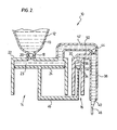
- Figures 1 and 2 schematically illustrates a first embodiment of a dispenser 10 which in accordance with a first embodiment of the present invention.
- the dispenser 10 comprises a reservoir 12 for fluid 13 to be dispensed, a first piston pump 14 and a second piston pump 16.
- the first piston pump 14 has a piston chamber-forming member 22 forming a first chamber 23 within which a first piston 24 is coaxially slidable.
- the piston chamber-forming member 22 has an inlet opening 26 and an outlet opening 28.
- a feed conduit 18 connects the reservoir 12 to the inlet opening 26 of the first piston pump 14.
- a one-way inlet valve 20 in the conduit 18 merely permits fluid flow through the conduit 18 from the reservoir 12 to the first chamber 23.
- the second piston pump 16 has a piston chamber-forming member 30 forming a second chamber 32 within which a second piston 34 is coaxially slidable.
- the piston chamber-forming member 30 has a communication opening 36.
- An outlet tube 38 is provided with an outlet 40 from which fluid is to be dispensed.
- the first pump outlet opening 28 is connected via an exit conduit 42 with the outlet tube 38.
- a one-way outlet valve 44 is provided which merely permits fluid flow through the exit conduit 42 from the first chamber 23 to the outlet tube 38.
- a communication conduit 50 extends from the communication opening 36 of the second chamber 32 to connect to the outlet tube 38 downstream from the one-way outlet valve 44.
- the first piston 24 and the second piston 34 are mechanically coupled via splint 46 for sliding in unison relative their respective piston chamber-forming members in reciprocal motion between the extended position shown in Figure 1 and the retracted position shown in Figure 2.
- fluid is drawn from the reservoir 12 into the first chamber 23 with the suction created in the first chamber 23 drawing fluid past the one-way inlet valve 20 and with the one-way outlet valve 44 preventing flow inwardly there through from the outlet tube 38.
- suction created within the second chamber 32 of the second piston pump 16 will draw fluid which is inside the outlet tube 38 downstream of the outlet valve 44 into the second chamber 32.
- fluid in the first chamber 23 is forced out of the first chamber 23 through the one-way outlet valve 44 into the outlet tube 38 and out the outlet 40.
- any fluid which is in the second chamber 32 is forced out of the second chamber 32 and into the outlet tube 38.
- Figure 2 illustrates a condition after a completed discharge stroke and shows a globule, drop or string 46 of fluid extending downwardly and out of the outlet 40.
- the pistons 24 and 34 are immediately moved toward the extended position as by a spring (not shown) which biases the pistons to the extended position.
- the fluid has been drawn back within the outlet tube 38 to a position that a meniscus 48 across the outlet tube 38 is withdrawn inside the outlet tube 38 inwardly from the outlet 40.
- This is advantageous in that in this position the fluid is less prone to drying or hardening.
- the obstruction will be internal within the outlet tube 38 and in subsequent dispensing if any fluid comes to be forced passed the obstruction, spraying will be prevented by reason of the obstruction being internal within the outlet tube 38 or at least any spraying can only occur in the same direction that the outlet tube is directed.
- a volume of liquid will be drawn back so as to fill the second chamber 32.
- This volume preferably bears a relation to the volume of the outlet tube 32 from the outlet 40 back to a location where the meniscus 48 is desired to be formed and of course having regard to the volume of the outlet tube 38, the volume of any expected globule, drop or string 46, and the extent to which fluid in the outlet tube 38 and any expected globule, drop or string 46 of fluid as shown in Figure 2 may be desired to be drawn back as well as the desired location of the meniscus 48.
- the fluid may be drawn back such that the outlet tube 38 is substantially cleared of fluid and the meniscus 48 may come to be disposed within the communication conduit 50 or inside the second piston chamber 32 itself. If all fluid downstream of the one-way outlet valve 44 is drawn back into the second chamber 32 whose communication opening 36 is directed upwardly then there is no fluid which under gravity may drip out the outlet 40, as can be advantageous as, for example, with low viscosity flowable materials to be dispensed.
- the relative volume of the second chamber 32 may be selected without having particular regard to the volume of the fluid dispensed in a stroke by the first piston 14.
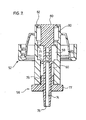
- the pump assembly comprises three principle elements, a piston chamber-forming body 52, a one-way inlet valve 54 and a piston 56.
- the body 52 carries an outer annular flange 53 with internal threads 55 which are adapted to engage threads of the neck of a bottle 57 shown in dashed lines only in Figure 3 which is to form a fluid reservoir.
- the body 52 includes an interior center tube 58 which provides a stepped cylindrical chamber having an inner cylindrical chamber 59 and an outer chamber 60.
- the outer chamber 60 is of a diameter greater than the diameter of the inner chamber 59.
- the inner chamber 59 has a cylindrical chamber wall 61, an inner end 62 and an outer end.
- the outer chamber 60 has a cylindrical chamber wall 64, an inner end 65 and an outer end 66.
- the inner and outer chambers are coaxially in the sense of being disposed about the same central axis 63.
- the outer and inner chambers are axially adjacent each other with the outer end of the inner chamber 59 opening into the inner end 65 of the outer chamber 60.
- Inlet openings 67 are provided in the inner end 62 of the inner chamber and the one-way valve 54 is disposed across the inlet openings 67.
- the inlet openings 67 provide communication with fluid in the bottle 57.
- the one-way valve 54 permits fluid flow from the bottle 57 into the chamber 59 but prevents fluid flow from the inner chamber 59 to the bottle.
- the one-way valve 54 comprises a shouldered button which is secured in snap fit relation inside a central opening in the inner end 62 of the inner chamber with a circular resilient flexing disc 69 extending radially from the button.
- the flexing disc 69 is sized to circumferentially abut the chamber wall 61 of the inner chamber 59 substantially preventing fluid flow there past from the inner chamber 59 to the bottle 57.
- the flexing disc 69 is deflectable away from the wall 61 to permit flow from the bottle into the inner chamber 59.
- the piston 56 is axially slidably received in the inner and outer chambers for reciprocal sliding motion inward and outwardly therein.
- the piston 56 is generally circular in cross-section and is slidably received within the chambers.
- the piston preferably is a unitary element formed entirely of plastic preferably by injection molding.
- the piston 56 has a hollow stem 70 extending along a central longitudinal axis 63 through the piston.
- a circular resilient flexing disc 71 is located at an inner end 72 of the piston and extends radially therefrom.
- the flexing disc 71 is sized to circumferentially abut the chamber wall 61 of the inner chamber 59 substantially preventing fluid flow therebetween inwardly.
- the flexing disc 71 is biased radially outwardly however is adapted to be deflected radially inwardly so as to permit fluid flow past the flexing disc 71 as from the inner chamber 59 into the outer chamber 60.
- An outer circular sealing disc 73 is located on the stem spaced axially outwardly from the flexing disc 71.
- the sealing disc 73 extends radially outwardly on the stem 70 to circumferentially engage the chamber wall 64 of the outer chamber 60 and to form a substantially fluid impermeable seal therebetween.
- the sealing disc 73 engages the chamber wall 64 of the outer chamber 60 to prevent flow there past both inwardly and outwardly.
- the piston stem 70 has a hollow central outlet passageway 74 extending along the axis of the piston from a closed inner end 75 located in the stem between the flexing disc 71 and the sealing disc 73 to an outlet 76 at an outer end of the piston.
- a channel extends radially from an inlet 78 located on the side of the stem between the flexing disc 71 and the sealing disc 73 extending radially inwardly through the stem into communication with the central passageway 74.
- the channel and central passageway 74 permit fluid communication through the piston past the sealing disc 73 between the inlet 78 and the outlet 76.
- An outer circular engagement flange 77 is provided on an outermost end portion of the stem which extends radially outwardly from the outer end 66 of the outer chamber 60.
- the flange 77 may be engaged by an actuating device (not shown) in order to move the piston 56 in and out of the body 52.
- Axially extending webs or ribs 79 may be provided to extend radially from the stem 70 to assist in maintaining the piston 56 in axially centred and aligned arrangement when sliding into and out of the chambers.
- the flexing disc 69 of the one-way valve 54 and the flexing disc 71 carried on the piston 56 each elastically deform away from the chamber wall 61 of the inner chamber 59 to prevent fluid flow in the inner chamber 59 past each disc outwardly.
- Figures 5 and 6 show a third embodiment of the invention in accordance with the present invention which is identical to the pump as shown in Figures 3 and 4 however the one-way valve 54 in Figures 5 and 6 has been replaced by providing an additional step to the chamber and providing an additional flexing disc on the piston.
- similar reference numerals are used in Figures 5 and 6 to refer to similar elements in Figures 3 and 4.
- the piston chamber-forming body 52 has three coaxial chambers of different size namely an outer chamber 61, an intermediate chamber 59 and an inner chamber 80 each coaxially and each of a successively smaller diameter.
- the piston stem 70 carries an inner extension 81 on which there is provided an inner flexing disc 82 which extends radially outwardly from the stem 70 to proximate a chamber wall 83 of the inner chamber 80 circumferentially thereabout.
- the inner flexing disc 82 elastically deforms away from the chamber wall 83 of the inner chamber 80 to permit fluid flow in the inner chamber 80 past the inner flexing disc 82 outwardly.
- the inner flexing disc 82 substantially prevents fluid flow in the inner chamber 80 past the flexing disc 82 inwardly.
- fluid in the outlet passageway 74 is drawn back through the outlet passageway 74 into the space between the intermediate flexing disc 71 and the outer sealing disc 73 due to the reduction in volume between the intermediate flexing disc 71 and outer sealing disc 73.
- Figure 7 which like the embodiment in Figures 5 and 6 also has a double stepped interior chamber with three chambers referred to as an inner chamber 80, an intermediate chamber 59 and an outer chamber 61. However in Figure 7 the chambers decreases in radius from the outer chamber 60 to the intermediate chamber 59 to the inner chamber 80.
- the inner flexible disc 82 and the intermediate flexible disc 71 effectively provide for one-way flow inwardly and the sealing disc 83 prevents fluid flow there past inwardly and outwardly.
- the volume between the sealing disc 83 and the intermediate flexible disc 71 increases thus drawing fluid back into the intermediate chamber 59 from the outlet passageway 74.
- engagement flange 77 and the centering webs 78 are shown as a separate element to be fixedly secured to the remainder of the piston 54 to facilitate assembly.
- the communication into the outlet passageway 74 need be merely between the flexible discs 71 and the sealing disc 73 on the piston and could for example be provided to extend into the sealing disc 73 and then through the sealing disc into the outlet passageway.
- the dispensing pump illustrated in the Figures may in a known manner be adapted for use with a collapsible reservoir or with a rigid non-collapsible reservoir.
- some mechanism may be provided to vent air into the reservoir in a known manner.
- the pump may be provided with suitable activating mechanism such as known levers and the like to movement of the piston in one direction with a biasing mechanism such as springs and the like to return the piston.
- suitable activating mechanism such as known levers and the like to movement of the piston in one direction
- biasing mechanism such as springs and the like to return the piston.
- Manually operated or mechanical activators may be used.
Abstract
Description
- Many dispensers of liquid such as hands soaps, creams, honey, ketchup and mustard and other viscous fluids which dispense fluid from a nozzle leave drop of liquid at the end of the outlet. This can be a problem that the liquid may harden, as creating an obstruction which reduces the area for fluid flow in future dispensing. The obstruction can result in future dispensing through a small area orifice resulting in spraying in various directions such as onto a wall or user to stain the wall or user or more disadvantageously into the eyes of a user.
- Many dispensers of material such as creams and for example liquid honey have the problem of stringing in which an elongate string of fluid hangs from fluid in the outlet and dangles from the outlet after dispensing an allotment of fluid. With passage of time the string may form into a droplet and drop from the outlet giving the appearance that the dispenser is leaking.
- Piston pumps as for soap dispensers are known as taught in U.S. Patent No. 5,676,277 to Ophardt issued October 14, 1997 which is incorporated herein by reference.
- To at least partially overcome these disadvantages of previously known devices the present invention provides a piston pump dispenser having a reciprocating piston pump arrangement which in a dispensing stroke dispenses fluid from an outlet and in a charging stroke to draw fluid from a reservoir also draws back fluid from the outlet through which fluid is dispensed in the dispensing stroke.
- The present invention is particularly applicable to fluid dispensers which fluid is to be dispensed out of an outlet with the outlet forming an open end of a tubular member. In many applications, the tubular member has its outlet opening downwardly and fluid passing through the tubular member is drawn downwardly by the forces of gravity.
- An object of the present invention is to provide a fluid dispenser in which after dispensing fluid out an outlet draws fluid back through the outlet to reduce dripping and/or stringing.
- An object of the present invention is to provide a simplified piston pump for dispensing fluid and after dispensing draws back fluid from the outlet of a nozzle from which the fluid has been dispensed.
- Accordingly, in one aspect the present invention provides a pump for a fluid dispenser, the pump comprising a first piston pump and a second piston pump,
- the first piston pump having a first chamber and a first piston reciprocally slidable in the first chamber between an extended and a retracted position, the first chamber having an inlet adapted for communication with a reservoir of fluid, the first chamber having an exit in communication with an outlet passageway having an outlet from which fluid is to be dispensed,
- a one-way inlet valve permitting fluid flow into the first chamber from the reservoir via the inlet but preventing fluid flow outwardly from the first chamber through the inlet;
- a one-way outlet valve permitting fluid flow to the outlet passageway from the first chamber via the exit but preventing fluid flow through the one-way outlet valve from the outlet passageway into the first chamber via the exit,
- the second pump having a second chamber and a second piston reciprocally slidable in the second chamber for movement between an extended position and a retracted position, a communication port opening into the second chamber in communication with the outlet passageway downstream of the one-way outlet valve,
- a coupling mechanism coupling the first piston and the second piston for movement in unison such that when the first piston pump dispenses fluid from the first chamber to the outlet passageway via the exit, the second piston pump dispenses fluid from the second chamber to the outlet passageway and when the first piston pump draws fluid into the first chamber past the one-way inlet valve, the second piston pump draws fluid through its communication port from the outlet passageway into the second chamber.
- In another aspect the present invention provides a pump for dispensing liquids from a reservoir, comprising:
- a piston-chamber forming member having a cylindrical inner chamber and a cylindrical outer chamber,
- the inner chamber and outer chamber each having a diameter, a chamber wall, an inner end and an outer end,
- the inner end of the inner chamber in fluid communication with a reservoir,
- the diameter of the inner chamber being less than the diameter of the outer chamber,
- the inner chamber and outer chamber being coaxial with the outer end of the inner chamber opening into the inner end of the outer chamber,
- a one-way valve between the reservoir and the inner chamber permitting fluid flow through the inner end of said inner chamber only from the reservoir to the inner chamber;
- a piston forming element received in the piston-chamber forming member axially slidable inwardly and outwardly therein,
- said piston forming element being generally circular in cross-section with a central axially extending hollow stem having a outlet passageway closed at an inner end and having an outlet proximate an outer end,
- a circular flexing disc extending radially outwardly from the stem proximate an inner end of the stem, the flexing disc having an elastically deformable edge portion proximate the chamber wall of the inner chamber circumferentially thereabout,
- a circular sealing disc extending radially outwardly from the stem spaced axially outwardly from the flexing disc, the sealing disc engaging the chamber wall of the outer chamber circumferentially thereabout to form a substantially fluid impermeable seal therewith on sliding of said piston forming element inwardly and outwardly,
- an inlet located on the stem between the flexing disc and sealing disc in communication with the outlet passageway,
- the piston forming element slidably received in the piston-chamber forming member for reciprocal axial inward and outward movement therein with the flexing disc in the inner chamber and sealing disc in the outer chamber,
- the flexing disc substantially preventing fluid flow in the inner chamber past the flexing disc in an inward direction,
- the flexing disc elastically deforming away from the chamber wall of the inner chamber to permit fluid flow in the inner chamber past the flexing disc outwardly.
- In a further aspect the present invention provides a pump for dispensing liquid from a reservoir comprising:
- a piston-chamber forming member having a cylindrical inner chamber, a cylindrical intermediate chamber and a cylindrical outer chamber, the inner chamber ,intermediate chamber and outer chamber each having a diameter, a chamber wall, an inner end and an outer end;
- wherein either:
- (a) the diameter of the inner chamber being less than the diameter of the intermediate chamber, and the diameter of the intermediate chamber being less than the diameter of the outer chamber, or
- (b) the diameter of the inner chamber being greater than the diameter of the intermediate chamber, and the diameter of the intermediate chamber being greater than the diameter of the outer chamber,
- the inner chamber, intermediate chamber and outer chamber being coaxial with the outer end of the inner chamber opening into the inner end of the intermediate chamber and the outer end of the intermediate chamber opening into the inner end of the outer chamber;
- the inner end of the inner chamber in fluid communication with a reservoir,
- a piston forming element received in the piston-chamber forming member axially slidable inwardly and outwardly therein,
- said piston forming element being generally circular in cross-section with a central axially extending hollow stem having a central outlet passageway closed at an inner end and having an outlet proximate an outer end,
- a circular inner flexing disc extending radially outwardly from the stem proximate an inner end of the stem, the inner flexing disc having an elastically deformable edge portion proximate the chamber wall of the inner chamber circumferentially thereabout,
- a circular intermediate flexing disc extending radially outwardly from the stem spaced axially outwardly from the inner flexing disc, the intermediate flexing disc having an elastically deformable edge portion proximate the chamber wall of the intermediate chamber circumferentially thereabout,
- a circular sealing disc extending radially outwardly from the stem spaced axially outwardly from the intermediate flexing disc, the sealing disc engaging the chamber wall of the outer chamber circumferentially thereabout to form a substantially fluid impermeable seal therewith on sliding of said piston forming element inwardly and outwardly,
- an inlet located on the stem between the intermediate flexing disc and the sealing disc in communication with the outlet passageway,
- the piston forming element slidably received in the piston chamber forming member for reciprocal axial inward and outward movement therein with the inner flexing disc in the inner chamber, the intermediate flexing disc in the intermediate chamber and the sealing disc in the outer chamber,
- the inner flexing disc substantially preventing fluid flow in the inner chamber past the inner flexing disc in an inward direction,
- the intermediate flexing disc substantially preventing fluid flow in the intermediate chamber past the intermediate flexing disc in an inward direction,
- the inner flexing disc elastically deforming away from the chamber wall of the inner chamber to permit fluid flow in the inner chamber past the inner flexing disc in an outward direction,
- the intermediate flexing disc elastically deforming away from the chamber wall of the intermediate chamber to permit fluid flow in the intermediate chamber past the intermediate flexing disc in an outward direction.
- Figure 1 is a schematic cross-sectional side view of a pump in accordance with a first embodiment of the present invention is a fully extended position;
- Figure 2 is a view identical to that in Figure 1 but in a retracted position;
- Figure 3 is a schematic cross-sectional side view of a pump in accordance with a second embodiment of the present invention is a fully extended position;
- Figure 4 is a view identical to that in Figure 3 but in a retracted position;
- Figure 5 is a schematic cross-sectional side view of a pump in accordance with a third embodiment of the present invention is a fully extended position;
- Figure 6 is a view identical to that in Figure 5 but in a retracted position;
- Figure 7 is a schematic cross-sectional side view of a pump in accordance with a fourth embodiment of the present invention in a fully retracted position.
- Reference is made first to Figures 1 and 2 which schematically illustrates a first embodiment of a
dispenser 10 which in accordance with a first embodiment of the present invention. - The
dispenser 10 comprises areservoir 12 forfluid 13 to be dispensed, afirst piston pump 14 and asecond piston pump 16. Thefirst piston pump 14 has a piston chamber-formingmember 22 forming afirst chamber 23 within which afirst piston 24 is coaxially slidable. The piston chamber-formingmember 22 has an inlet opening 26 and an outlet opening 28. - A
feed conduit 18 connects thereservoir 12 to the inlet opening 26 of thefirst piston pump 14. A one-way inlet valve 20 in theconduit 18 merely permits fluid flow through theconduit 18 from thereservoir 12 to thefirst chamber 23. - The
second piston pump 16 has a piston chamber-formingmember 30 forming asecond chamber 32 within which asecond piston 34 is coaxially slidable. The piston chamber-formingmember 30 has acommunication opening 36. - An
outlet tube 38 is provided with anoutlet 40 from which fluid is to be dispensed. - The first
pump outlet opening 28 is connected via anexit conduit 42 with theoutlet tube 38. A one-way outlet valve 44 is provided which merely permits fluid flow through theexit conduit 42 from thefirst chamber 23 to theoutlet tube 38. - A
communication conduit 50 extends from thecommunication opening 36 of thesecond chamber 32 to connect to theoutlet tube 38 downstream from the one-way outlet valve 44. - The
first piston 24 and thesecond piston 34 are mechanically coupled viasplint 46 for sliding in unison relative their respective piston chamber-forming members in reciprocal motion between the extended position shown in Figure 1 and the retracted position shown in Figure 2. In moving from the retracted position to the extended position in a charging stroke, fluid is drawn from thereservoir 12 into thefirst chamber 23 with the suction created in thefirst chamber 23 drawing fluid past the one-way inlet valve 20 and with the one-way outlet valve 44 preventing flow inwardly there through from theoutlet tube 38. In this charging stroke, suction created within thesecond chamber 32 of thesecond piston pump 16 will draw fluid which is inside theoutlet tube 38 downstream of theoutlet valve 44 into thesecond chamber 32. - In moving from the extended position to the retracted position in a discharge stroke, fluid in the
first chamber 23 is forced out of thefirst chamber 23 through the one-way outlet valve 44 into theoutlet tube 38 and out theoutlet 40. At the same time, any fluid which is in thesecond chamber 32 is forced out of thesecond chamber 32 and into theoutlet tube 38. - Figure 2 illustrates a condition after a completed discharge stroke and shows a globule, drop or
string 46 of fluid extending downwardly and out of theoutlet 40. On completion of the discharge stroke, preferably thepistons - As seen in Figure 1, the fluid has been drawn back within the
outlet tube 38 to a position that ameniscus 48 across theoutlet tube 38 is withdrawn inside theoutlet tube 38 inwardly from theoutlet 40. This is advantageous in that in this position the fluid is less prone to drying or hardening. Moreover if there is any drying or hardening that leads to an obstruction, the obstruction will be internal within theoutlet tube 38 and in subsequent dispensing if any fluid comes to be forced passed the obstruction, spraying will be prevented by reason of the obstruction being internal within theoutlet tube 38 or at least any spraying can only occur in the same direction that the outlet tube is directed. - In a charging stroke, in the
piston 34 of thesecond piston pump 16 moving from the retracted to the extended position, a volume of liquid will be drawn back so as to fill thesecond chamber 32. This volume preferably bears a relation to the volume of theoutlet tube 32 from theoutlet 40 back to a location where themeniscus 48 is desired to be formed and of course having regard to the volume of theoutlet tube 38, the volume of any expected globule, drop orstring 46, and the extent to which fluid in theoutlet tube 38 and any expected globule, drop orstring 46 of fluid as shown in Figure 2 may be desired to be drawn back as well as the desired location of themeniscus 48. - If desired, the fluid may be drawn back such that the
outlet tube 38 is substantially cleared of fluid and themeniscus 48 may come to be disposed within thecommunication conduit 50 or inside thesecond piston chamber 32 itself. If all fluid downstream of the one-way outlet valve 44 is drawn back into thesecond chamber 32 whosecommunication opening 36 is directed upwardly then there is no fluid which under gravity may drip out theoutlet 40, as can be advantageous as, for example, with low viscosity flowable materials to be dispensed. - Since the
second pump 16 is to discharge in a dispensing stroke, the same amount of material as it is to suck back during a charging stroke, the relative volume of thesecond chamber 32 may be selected without having particular regard to the volume of the fluid dispensed in a stroke by thefirst piston 14. - Reference is made to Figures 3 and 4 which show a schematic second embodiment of a draw back dispensing pump assembly in accordance with the present invention.
- The pump assembly comprises three principle elements, a piston chamber-forming
body 52, a one-way inlet valve 54 and apiston 56. Thebody 52 carries an outer annular flange 53 with internal threads 55 which are adapted to engage threads of the neck of abottle 57 shown in dashed lines only in Figure 3 which is to form a fluid reservoir. - The
body 52 includes aninterior center tube 58 which provides a stepped cylindrical chamber having an innercylindrical chamber 59 and anouter chamber 60. Theouter chamber 60 is of a diameter greater than the diameter of theinner chamber 59. Theinner chamber 59 has acylindrical chamber wall 61, aninner end 62 and an outer end. Theouter chamber 60 has acylindrical chamber wall 64, aninner end 65 and anouter end 66. The inner and outer chambers are coaxially in the sense of being disposed about the samecentral axis 63. The outer and inner chambers are axially adjacent each other with the outer end of theinner chamber 59 opening into theinner end 65 of theouter chamber 60.Inlet openings 67 are provided in theinner end 62 of the inner chamber and the one-way valve 54 is disposed across theinlet openings 67. Theinlet openings 67 provide communication with fluid in thebottle 57. The one-way valve 54 permits fluid flow from thebottle 57 into thechamber 59 but prevents fluid flow from theinner chamber 59 to the bottle. - The one-
way valve 54 comprises a shouldered button which is secured in snap fit relation inside a central opening in theinner end 62 of the inner chamber with a circularresilient flexing disc 69 extending radially from the button. Theflexing disc 69 is sized to circumferentially abut thechamber wall 61 of theinner chamber 59 substantially preventing fluid flow there past from theinner chamber 59 to thebottle 57. Theflexing disc 69 is deflectable away from thewall 61 to permit flow from the bottle into theinner chamber 59. - The
piston 56 is axially slidably received in the inner and outer chambers for reciprocal sliding motion inward and outwardly therein. - The
piston 56 is generally circular in cross-section and is slidably received within the chambers. The piston preferably is a unitary element formed entirely of plastic preferably by injection molding. Thepiston 56 has ahollow stem 70 extending along a centrallongitudinal axis 63 through the piston. - A circular
resilient flexing disc 71 is located at an inner end 72 of the piston and extends radially therefrom. Theflexing disc 71 is sized to circumferentially abut thechamber wall 61 of theinner chamber 59 substantially preventing fluid flow therebetween inwardly. Theflexing disc 71 is biased radially outwardly however is adapted to be deflected radially inwardly so as to permit fluid flow past theflexing disc 71 as from theinner chamber 59 into theouter chamber 60. - An outer
circular sealing disc 73 is located on the stem spaced axially outwardly from theflexing disc 71. Thesealing disc 73 extends radially outwardly on thestem 70 to circumferentially engage thechamber wall 64 of theouter chamber 60 and to form a substantially fluid impermeable seal therebetween. Preferably thesealing disc 73 engages thechamber wall 64 of theouter chamber 60 to prevent flow there past both inwardly and outwardly. - The piston stem 70 has a hollow
central outlet passageway 74 extending along the axis of the piston from a closed inner end 75 located in the stem between the flexingdisc 71 and thesealing disc 73 to anoutlet 76 at an outer end of the piston. A channel extends radially from aninlet 78 located on the side of the stem between the flexingdisc 71 and thesealing disc 73 extending radially inwardly through the stem into communication with thecentral passageway 74. The channel andcentral passageway 74 permit fluid communication through the piston past thesealing disc 73 between theinlet 78 and theoutlet 76. - An outer
circular engagement flange 77 is provided on an outermost end portion of the stem which extends radially outwardly from theouter end 66 of theouter chamber 60. Theflange 77 may be engaged by an actuating device (not shown) in order to move thepiston 56 in and out of thebody 52. Axially extending webs orribs 79 may be provided to extend radially from thestem 70 to assist in maintaining thepiston 56 in axially centred and aligned arrangement when sliding into and out of the chambers. - In moving from a retracted position as shown in Figure 4 to an extended position of Figure 3 in a charging stroke, suction is created in the
inner chamber 59 in that theflexing disc 71 effectively acts as a one-way valve preventing flow inwardly there past such that movement of thepiston 56 outwardly creates suction in theinner chamber 59 which draws fluid from the bottle past the inlet one-way valve 54. At the same time, a vacuum is formed in theouter chamber 60 to suck fluid within theoutlet passageway 74 back into theouter chamber 60. Suction arises in theouter chamber 60 on thepiston 54 moving outwardly in that theouter chamber 60 has a diameter larger than the diameter of theinner chamber 59 and thus with thepiston 54 moving outwardly, the volume between the flexingdisc 71 and thesealing disc 73 increases. - In a discharge stroke, when the
piston 54 moves inwardly, fluid within theinner chamber 59 is compressed between theflexible disc 71 and the one-way inlet valve 54. The one-way inlet valve 54 effectively closes under pressure and as pressure is developed within theinner chamber 59, theflexible disc 71 deflects to permit fluid to pass downwardly past theflexible disc 71 to between theflexible disc 71 and thesealing disc 73 and hence via theinlet 78 to theoutlet passageway 74 and out theoutlet 76. With movement of the piston inwardly, the volume between theflexible disc 71 and thesealing disc 73 decreases which will also discharging fluid via theinlet 78 to theoutlet passageway 74 and out theoutlet 76. - The
flexing disc 69 of the one-way valve 54 and theflexing disc 71 carried on thepiston 56 each elastically deform away from thechamber wall 61 of theinner chamber 59 to prevent fluid flow in theinner chamber 59 past each disc outwardly. - Reference is made to Figures 5 and 6 which show a third embodiment of the invention in accordance with the present invention which is identical to the pump as shown in Figures 3 and 4 however the one-
way valve 54 in Figures 5 and 6 has been replaced by providing an additional step to the chamber and providing an additional flexing disc on the piston. In Figures 5 and 6 similar reference numerals are used in Figures 5 and 6 to refer to similar elements in Figures 3 and 4. - In Figures 5 and 6 the piston chamber-forming
body 52 has three coaxial chambers of different size namely anouter chamber 61, anintermediate chamber 59 and aninner chamber 80 each coaxially and each of a successively smaller diameter. The piston stem 70 carries aninner extension 81 on which there is provided aninner flexing disc 82 which extends radially outwardly from thestem 70 to proximate achamber wall 83 of theinner chamber 80 circumferentially thereabout. Theinner flexing disc 82 elastically deforms away from thechamber wall 83 of theinner chamber 80 to permit fluid flow in theinner chamber 80 past theinner flexing disc 82 outwardly. Theinner flexing disc 82 substantially prevents fluid flow in theinner chamber 80 past theflexing disc 82 inwardly. - Operation of the embodiment of Figures 5 and 6 is substantially the same as that described with the reference to Figures 3 and 4 with a notable difference that with inward movement of the
piston 56 from the extended position of Figure 5 to the retracted position of Figure 6, the volume between the innerflexible disc 82 and the intermediateflexible disc 71 decreases forcing fluid which cannot pass upwardly past theinner flexing disc 82 to exit past theintermediate flexing disc 71 downwardly. Similarly, in a charging stroke on thepiston 56 moving from the retracted position of Figure 6 to the extended position of Figure 5 the volume between theinner flexing disc 82 and theintermediate flexing disc 71 increases thus drawing the fluid from the bottle past theinner flexing disc 82. In the charging stroke, as is the case with the other embodiments, fluid in theoutlet passageway 74 is drawn back through theoutlet passageway 74 into the space between theintermediate flexing disc 71 and theouter sealing disc 73 due to the reduction in volume between theintermediate flexing disc 71 andouter sealing disc 73. - Reference is made to Figure 7 which like the embodiment in Figures 5 and 6 also has a double stepped interior chamber with three chambers referred to as an
inner chamber 80, anintermediate chamber 59 and anouter chamber 61. However in Figure 7 the chambers decreases in radius from theouter chamber 60 to theintermediate chamber 59 to theinner chamber 80. In a discharge stroke thepiston 54 is moved outwardly and in a charging stroke thepiston 54 is moved inwardly. The innerflexible disc 82 and the intermediateflexible disc 71 effectively provide for one-way flow inwardly and thesealing disc 83 prevents fluid flow there past inwardly and outwardly. In a similar manner to that effectively described with reference 5 and 6, during a charging stroke when the piston is moving inwardly, the volume between the sealingdisc 83 and the intermediateflexible disc 71 increases thus drawing fluid back into theintermediate chamber 59 from theoutlet passageway 74. - In the embodiment of Figure 7, the
engagement flange 77 and the centeringwebs 78 are shown as a separate element to be fixedly secured to the remainder of thepiston 54 to facilitate assembly. - In each of the embodiments, the
channel inlet 78 through thestem 70 to theoutlet passageway 74 shown as being disposed as a radially extending through a tubular wall of thestem 70 between theflexible disc 71 and thesealing disc 73. The communication into theoutlet passageway 74 need be merely between theflexible discs 71 and thesealing disc 73 on the piston and could for example be provided to extend into thesealing disc 73 and then through the sealing disc into the outlet passageway. - The dispensing pump illustrated in the Figures may in a known manner be adapted for use with a collapsible reservoir or with a rigid non-collapsible reservoir. When used with a rigid non-collapsible reservoir then some mechanism may be provided to vent air into the reservoir in a known manner.
- The pump may be provided with suitable activating mechanism such as known levers and the like to movement of the piston in one direction with a biasing mechanism such as springs and the like to return the piston. Manually operated or mechanical activators may be used.
- While the invention has been described with reference to preferred embodiments many variations and modifications will now occur to persons skilled in the art. For a definition of the invention reference is made to the appended claims.
Claims (18)
- A pump for a fluid dispenser, the pump comprising:a first piston pump (14) and a second piston pump (16),the first piston pump (14) having a first chamber (23) and a first piston (24) reciprocally slidable in the first chamber (23) between an extended and a retracted position,the first chamber (23) having an inlet (26) adapted for communication with a reservoir (12) of fluid (13),the first chamber (23) having an exit (28) in communication with an outlet passageway (38) having an outlet (40) from which fluid is to be dispensed,a one-way inlet valve (20) permitting fluid flow into the first chamber (23) from the reservoir (12) via the inlet (26) but preventing fluid flow outwardly from the first chamber (23) through the inlet;a one-way outlet valve (44) permitting fluid flow to the outlet passageway (38) from the first chamber (23) via the exit (28) but preventing fluid flow through the one-way outlet valve (44) from the outlet passageway (38) into the first chamber (23) via the exit (28),the second pump (16) having a second chamber (32) and a second piston (34) reciprocally slidable in the second chamber (32) for movement between an extended position and a retracted position,a communication port (36) opening into the second chamber (32) in communication with the outlet passageway (38) downstream of the one-way outlet valve (44),a coupling mechanism coupling (46) the first piston (24) and the second piston (34) for movement in unison such that when the first piston pump (14) dispenses fluid from the first chamber (23) to the outlet passageway (38) via the exit (28), the second piston (34) dispenses fluid from the second chamber (32) to the outlet passageway (38) and when the first piston pump (14) draws fluid into the first chamber (23) past the one-way inlet valve (20), the second piston pump (16) draws fluid through its communication port (36) from the outlet passageway (38) into the second chamber (32).
- A pump (14) as claimed in claim 1 wherein the first piston (24) and the second piston (34) are mechanically coupled together for movement in unison.
- A pump (14) as claimed in claim 2 wherein the first piston (24) and second piston (34) are coaxially disposed for coaxially sliding within a piston chamber-forming member (22) providing the first piston chamber (23) and the second piston chamber (32) coaxially therein.
- A pump (14) as claimed in claim 1 wherein in a charge stroke, the first piston (24) and the second piston (34) are moved respectively relative to the first chamber (23) and the second chamber (32) in the same direction with the movement of the first piston (24) in the first chamber (23) drawing fluid into the first chamber (23) through the one-way inlet valve (20), and the movement of the second piston (34) in the second chamber (32) drawing fluid into the second chamber (32) from the outlet passageway.
- A pump (14) as claimed in claim 4 wherein the first chamber (23) and the second chamber (32) are cylindrical, the second chamber (32) having a diameter different than a diameter of the first chamber (23).
- A pump (14) as claimed in claim 5 wherein the first chamber (23) and the second chamber (32) are coaxial, the exit from the second piston chamber opening into the first chamber, the one-way outlet valve (44) disposed across the exit of the first chamber (23) wherein fluid to be discharged from the first chamber passes through the second chamber (32).
- A pump (14) as claimed in claim 6 wherein in the charge stroke suction is created in both the first chamber (23) and the second chamber (32) with the one-way outlet valve (44) preventing suction from the first chamber (23) acting on fluid in the second chamber (32).
- A pump for dispensing liquids from a reservoir, comprising:a piston-chamber forming member (52) having a cylindrical inner chamber (59) and a cylindrical outer chamber (60),the inner chamber (59) and outer chamber (60) each having a diameter, a chamber wall, an inner end and an outer end,the inner end (62) of the inner chamber (59) in fluid communication with a reservoir,the diameter of the inner chamber (59) being less than the diameter of the outer chamber (60),the inner chamber (59) and outer chamber (60) being coaxial with the outer end of the inner chamber opening into the inner end (65) of the outer chamber (60),a one-way valve (54) between the reservoir and the inner chamber (59) permitting fluid flow through the inner end of said inner chamber only from the reservoir to the inner chamber (59);a piston forming element (56) received in the piston-chamber forming (52) member axially slidable inwardly and outwardly therein,said piston forming element (56) being generally circular in cross-section with a central axially extending hollow stem (70) having a outlet passageway (74) closed at an inner end and having an outlet (76) proximate an outer end,a circular flexing disc (71) extending radially outwardly from the stem (70) proximate an inner end of the stem, the flexing disc (71) having an elastically deformable edge portion proximate the chamber wall (61) of the inner chamber (59) circumferentially thereabout,a circular sealing disc (73) extending radially outwardly from the stem (70) spaced axially outwardly from the flexing disc (71), the sealing disc (73) engaging the chamber wall (64) of the outer chamber (60) circumferentially thereabout to form a substantially fluid impermeable seal therewith on sliding of said piston forming element (56) inwardly and outwardly,an inlet (78) located on the stem between the flexing disc (71) and sealing disc (73) in communication with the outlet passageway (74),the piston forming element (56) slidably received in the piston-chamber forming member (52) for reciprocal axial inward and outward movement therein with the flexing disc (71) in the inner chamber (59) and sealing disc (73) in the outer chamber (60),the flexing disc (71) substantially preventing fluid flow in the inner chamber (59) past the flexing disc (71) in an inward direction,the flexing disc (71) elastically deforming away from the chamber wall (61) of the inner chamber (59) to permit fluid flow in the inner chamber (59) past the flexing disc outwardly.
- A pump as claimed in claim 8 including an engagement flange (77) on said stem (70) outward of the piston chamber forming member (52) for engagement to move the piston forming element (56) inwardly and outwardly.
- A pump for dispensing liquid from a reservoir comprising:wherein either:a piston-chamber forming member (52) having a cylindrical inner chamber (80), a cylindrical intermediate chamber (59) and a cylindrical outer chamber (61), the inner chamber, intermediate chamber and outer chamber each having a diameter, a chamber wall, an inner end and an outer end;the inner chamber (80), intermediate chamber (59) and outer chamber (61) being coaxial with the outer end of the inner chamber (80) opening into the inner end of the intermediate chamber (59) and the outer end of the intermediate chamber (59) opening into the inner end of the outer chamber (61);(a) the diameter of the inner chamber (80) being less than the diameter of the intermediate chamber (59), and the diameter of the intermediate chamber (59) being less than the diameter of the outer chamber (61), or(b) the diameter of the inner chamber (80) being greater than the diameter of the intermediate chamber (59), and the diameter of the intermediate chamber (59) being greater than the diameter of the outer chamber (61),
the inner end of the inner chamber (80) in fluid communication with a reservoir,
a piston forming element (56) received in the piston-chamber forming member (52) axially slidable inwardly and outwardly therein,
said piston forming element (56) being generally circular in cross-section with a central axially extending hollow stem (70) having a central outlet passageway (74) closed at an inner end and having an outlet (76) proximate an outer end,
a circular inner flexing disc (82) extending radially outwardly from the stem (70) proximate an inner end of the stem (70), the inner flexing disc (82) having an elastically deformable edge portion proximate the chamber wall of the inner chamber (80) circumferentially thereabout,
a circular intermediate flexing disc (71) extending radially outwardly from the stem (70) spaced axially outwardly from the inner flexing disc (82), the intermediate flexing disc (71) having an elastically deformable edge portion proximate the chamber wall of the intermediate chamber (59) circumferentially thereabout,
a circular sealing disc (73) extending radially outwardly from the stem (70) spaced axially outwardly from the intermediate flexing disc (71), the sealing disc (73) engaging the chamber wall of the outer chamber (61) circumferentially thereabout to form a substantially fluid impermeable seal therewith on sliding of said piston forming element inwardly and outwardly,
an inlet (78) located on the stem (70) between the intermediate flexing disc (71) and the sealing disc (73) in communication with the outlet passageway (74),
the piston forming element (56) slidably received in the piston chamber forming member (52) for reciprocal axial inward and outward movement therein with the inner flexing disc (82) in the inner chamber (80), the intermediate flexing disc (71) in the intermediate chamber (59) and the sealing disc (73) in the outer chamber (61),
the inner flexing disc (82) substantially preventing fluid flow in the inner chamber (80) past the inner flexing disc (82) in an inward direction,
the intermediate flexing disc (71) substantially preventing fluid flow in the intermediate chamber (59) past the intermediate flexing disc (71) in an inward direction,
the inner flexing disc (82) elastically deforming away from the chamber wall of the inner chamber (80) to permit fluid flow in the inner chamber past the inner flexing disc (82) in an outward direction,
the intermediate flexing disc (71) elastically deforming away from the chamber wall of the intermediate chamber (59) to permit fluid flow in the intermediate chamber (59) past the intermediate flexing disc (71) in an outward direction. - A pump (14) as claimed in claim 10 wherein the diameter of the inner chamber (80) is less than the diameter of the intermediate chamber (59) and the diameter of the intermediate chamber (59) is less than the diameter of the outer chamber (61).
- A pump (14) as claimed in claim 10 wherein the diameter of the inner chamber (80) is greater than the diameter of the intermediate chamber (59) and the diameter of the intermediate chamber (59) is greater than the diameter of the outer chamber (61).
- A pump (14) as claimed in claim 10 wherein:said piston forming element (56) extends outwardly from the outer end of the outer chamber (60), andan engagement flange (77) is provided on the piston forming element (56) outward of the piston-chamber forming member (52) for engagement to move the piston forming element (56) inwardly and outwardly.
- A pump (14) as claimed in claim 13 wherein:the engagement flange (77) comprises a circular flange extending radially outwardly from said stem (70).
- A pump (14) as claimed in claim 9 including a plurality of axially extending webs (79) on said stem (70) extending radially outwardly from the stem to engage the chamber wall of at least one of the inner chamber (80), intermediate chamber (59) and outer chamber (61) and guide the piston forming element (56) in sliding axially centred alignment within the outer chamber (61).
- A pump (14) as claimed in claim 9 wherein the piston forming element (56) consists of a unitary element formed entirely of plastic by injection molding.
- A drawback pump for dispensing fluids from a reservoir, the pump comprising a double headed piston reciprocally slidable in a double chambered piston cylinder having an inlet communicating with the reservoir and an outlet passageway;
wherein, in a first stroke of the piston relative the cylinder, fluid in the cylinder is dispensed from the cylinder via the outlet passageway, and
in a second return stroke of the piston relative the cylinder, fluid is drawn into the cylinder from the reservoir via the inlet and, simultaneously, fluid in the outlet passageway is drawn back into the cylinder. - A pump as claimed in claim 17 wherein:in the second return stroke, fluid is drawn back from the outlet passageway sufficiently to merely reduce the volume of fluid in the outlet passageway.
Applications Claiming Priority (2)
| Application Number | Priority Date | Filing Date | Title |
|---|---|---|---|
| CA002470532A CA2470532C (en) | 2004-06-09 | 2004-06-09 | Draw back pump |
| CA2470532 | 2004-06-09 |
Publications (3)
| Publication Number | Publication Date |
|---|---|
| EP1604600A2 true EP1604600A2 (en) | 2005-12-14 |
| EP1604600A3 EP1604600A3 (en) | 2006-03-22 |
| EP1604600B1 EP1604600B1 (en) | 2019-08-28 |
Family
ID=34979281
Family Applications (1)
| Application Number | Title | Priority Date | Filing Date |
|---|---|---|---|
| EP05012460.1A Active EP1604600B1 (en) | 2004-06-09 | 2005-06-09 | Draw back pump |
Country Status (3)
| Country | Link |
|---|---|
| US (1) | US7267251B2 (en) |
| EP (1) | EP1604600B1 (en) |
| CA (1) | CA2470532C (en) |
Cited By (6)
| Publication number | Priority date | Publication date | Assignee | Title |
|---|---|---|---|---|
| EP2228139A1 (en) * | 2009-03-10 | 2010-09-15 | Gotohti.Com Inc. | Doubled seal disk for piston pump |
| WO2011004184A1 (en) * | 2009-07-10 | 2011-01-13 | Reckitt & Colman (Overseas) Limited | A fluid delivery system |
| WO2013037920A3 (en) * | 2011-09-13 | 2013-05-30 | Volkswagen Varta Microbattery Forschungsgesellschaft Mbh & Co. Kg | Intermittent coating of moving surfaces |
| EP2275014A3 (en) * | 2009-07-14 | 2014-07-02 | Gotohti.Com Inc. | Draw back push pump |
| US8939325B2 (en) | 2010-12-09 | 2015-01-27 | Reckitt & Colman (Overseas) Limited | Dispenser for a foaming liquid composition with improved foam recovery feature |
| EP2548487A3 (en) * | 2008-06-12 | 2017-06-28 | Gotohti.com Inc. | Withdrawal discharging piston pump |
Families Citing this family (40)
| Publication number | Priority date | Publication date | Assignee | Title |
|---|---|---|---|---|
| CA2517326C (en) * | 2005-04-22 | 2012-09-18 | Gotohti.Com Inc. | Foam pump with spring |
| US7770874B2 (en) | 2005-04-22 | 2010-08-10 | Gotohii.com Inc. | Foam pump with spring |
| CA2791887C (en) | 2005-04-22 | 2014-10-07 | Gotohti.Com Inc. | Foam pump with bellows spring |
| CA2545905A1 (en) * | 2006-05-05 | 2007-11-05 | Gotohti.Com Inc. | Stepped cylinder piston pump |
| CA2591046A1 (en) * | 2007-06-08 | 2008-12-08 | Gotohti.Com Inc. | Vacuum release mechanism for piston valve |
| CA2613785C (en) * | 2007-12-07 | 2015-03-24 | Gotohti.Com Inc. | Angled slot foam dispenser |
| DE602009000434D1 (en) * | 2008-05-29 | 2011-01-20 | Gojo Ind Inc | Pull-operated foam pump |
| US8235689B2 (en) * | 2008-11-03 | 2012-08-07 | Gojo Industries, Inc. | Piston pump with rotating pump actuator |
| US8157134B2 (en) * | 2008-12-05 | 2012-04-17 | Gotohti.Com Inc. | Piston with guide rings |
| EP2193736B1 (en) | 2008-12-08 | 2018-10-03 | OP-Hygiene IP GmbH | Engagement flange for removable dispenser cartridge |
| US8413852B2 (en) | 2008-12-08 | 2013-04-09 | Gotohti.Com Inc. | Ramped actuator for engagement flange on removable dispenser cartridge |
| US8113388B2 (en) | 2008-12-08 | 2012-02-14 | Heiner Ophardt | Engagement flange for removable dispenser cartridge |
| US8113389B2 (en) * | 2008-12-08 | 2012-02-14 | Kimberly-Clark Worldwide, Inc. | Anti drip fluid dispenser |
| CA2687879C (en) * | 2009-12-08 | 2016-11-01 | Gotohti.Com Inc. | Piston with frangible piston stop |
| CA2698915C (en) | 2010-04-01 | 2017-06-27 | Gotohti.Com Inc. | Stationary stem pump |
| CA2719635C (en) | 2010-11-01 | 2017-10-31 | Gotohti.Com Inc. | Telescopic piston for pump |
| CA2722646C (en) * | 2010-11-26 | 2018-01-02 | Gotohti.Com Inc. | Air assisted severance of viscous fluid stream |
| CA2799509C (en) | 2011-12-22 | 2019-07-30 | Gotohti.Com Inc. | Ramp actuator for engagement flange on removable dispenser cartridge |
| CA2772507C (en) | 2012-03-20 | 2018-12-18 | Gotohti.Com Inc. | Adaptive preload pump |
| CA2773201C (en) * | 2012-03-30 | 2019-06-25 | Gotohti.Com Inc. | Variable volume bore piston pump |
| CA2808550C (en) | 2012-06-19 | 2021-07-20 | Gotohti.Com Inc. | Drawback check valve |
| CA2780503C (en) | 2012-06-19 | 2019-05-21 | Gotohti.Com Inc. | Telescopic bell piston for pump |
| US9175674B2 (en) | 2012-06-19 | 2015-11-03 | Gotohti.Com Inc. | Drawback check valve |
| US9220377B2 (en) | 2012-08-02 | 2015-12-29 | Rubbermaid Commercial Products, Llc | Foam dispensing pump with decompression feature |
| AU2015209091A1 (en) | 2014-01-27 | 2016-09-08 | Gojo Industries, Inc. | Dispenser and refill unit having collapsible outlet tube |
| CA2841279C (en) | 2014-01-29 | 2021-11-23 | Heiner Ophardt | Multiple air chamber foam pump |
| US9850059B2 (en) * | 2014-03-20 | 2017-12-26 | Gojo Industries, Inc | Closed system for venting a dispenser reservoir |
| CA2848857C (en) | 2014-04-11 | 2022-10-18 | Op-Hygiene Ip Gmbh | Pump maintaining container internal pressure |
| CA3102626C (en) | 2014-08-29 | 2023-02-14 | Op-Hygiene Ip Gmbh | Pump assembly carrying rasp |
| CA2866055A1 (en) | 2014-08-29 | 2016-02-29 | Op-Hygiene Ip Gmbh | Displacement pump |
| CA2902751C (en) | 2015-09-01 | 2022-10-18 | Op-Hygiene Ip Gmbh | Air assisted severance of fluid stream |
| CA2902754C (en) | 2015-09-01 | 2023-04-11 | Op-Hygiene Ip Gmbh | Liquid hand cleaner dispensing as spray and liquid stream |
| WO2018044617A1 (en) * | 2016-08-29 | 2018-03-08 | Silgan Dispensing Systems Corporation | Inline vacuum spring sustained duration sprayer |
| AU2017383093A1 (en) * | 2016-12-22 | 2019-06-20 | Ego Pharmaceuticals Pty Ltd | Bottle cap |
| WO2018156615A1 (en) * | 2017-02-22 | 2018-08-30 | Gojo Industries, Inc. | Dispensers, refill units and pumps having vacuum actuated antidrip mechanisms |
| CA3000244A1 (en) | 2018-04-04 | 2019-10-04 | Op-Hygiene Ip Gmbh | Fluid pump with whistle |
| CA3025843A1 (en) | 2018-11-29 | 2020-05-29 | Op-Hygiene Ip Gmbh | Valve retention under pressure |
| CA3147756A1 (en) | 2019-07-25 | 2021-01-28 | Gojo Industries, Inc. | Pumps with positive pressure venting, refill units and dispensers |
| CA3096073A1 (en) | 2019-10-15 | 2021-04-15 | Op-Hygiene Ip Gmbh | Foam dispenser with ionic wind driven ozone generation and air circulation |
| US11084052B2 (en) * | 2019-12-31 | 2021-08-10 | Op-Hygiene Ip Gmbh | Stationary outlet stem pump |
Citations (1)
| Publication number | Priority date | Publication date | Assignee | Title |
|---|---|---|---|---|
| US5676277A (en) | 1991-05-20 | 1997-10-14 | Ophardt; Heiner | Disposable plastic liquid pump |
Family Cites Families (9)
| Publication number | Priority date | Publication date | Assignee | Title |
|---|---|---|---|---|
| US4781312A (en) | 1986-07-03 | 1988-11-01 | Strazdins (International) Pty. Limited | Liquid dispenser |
| US4949874A (en) | 1987-12-04 | 1990-08-21 | Henkel Kommanditgesellschaft Auf Aktien | Device for dispensing at least two flowable substances |
| US4991747A (en) | 1988-10-11 | 1991-02-12 | Risdon Corporation | Sealing pump |
| US5339990A (en) | 1992-11-10 | 1994-08-23 | Wilder Robert E | Adjustable pump dispenser |
| US5458289A (en) | 1993-03-01 | 1995-10-17 | Bespak Plc | Liquid dispensing apparatus with reduced clogging |
| US5836482A (en) | 1997-04-04 | 1998-11-17 | Ophardt; Hermann | Automated fluid dispenser |
| DE19901027A1 (en) | 1999-01-14 | 2000-07-27 | Ophardt Product Gmbh & Co | Piston pump for dispensing e.g. liquid soap, hand cream or disinfectant, contains replaceable valves in piston and cylinder for altering dosing volume |
| CA2341659C (en) | 2001-03-20 | 2007-08-07 | Hygiene-Technik Inc. | Liquid dispenser for dispensing foam |
| US6557736B1 (en) | 2002-01-18 | 2003-05-06 | Heiner Ophardt | Pivoting piston head for pump |
-
2004
- 2004-06-09 CA CA002470532A patent/CA2470532C/en active Active
- 2004-09-13 US US10/938,701 patent/US7267251B2/en active Active
-
2005
- 2005-06-09 EP EP05012460.1A patent/EP1604600B1/en active Active
Patent Citations (1)
| Publication number | Priority date | Publication date | Assignee | Title |
|---|---|---|---|---|
| US5676277A (en) | 1991-05-20 | 1997-10-14 | Ophardt; Heiner | Disposable plastic liquid pump |
Cited By (17)
| Publication number | Priority date | Publication date | Assignee | Title |
|---|---|---|---|---|
| EP2548487A3 (en) * | 2008-06-12 | 2017-06-28 | Gotohti.com Inc. | Withdrawal discharging piston pump |
| US8500416B2 (en) | 2009-03-10 | 2013-08-06 | Gotohti.Com | Doubled seal disk for piston pump |
| EP2228139A1 (en) * | 2009-03-10 | 2010-09-15 | Gotohti.Com Inc. | Doubled seal disk for piston pump |
| AU2010270052B2 (en) * | 2009-07-10 | 2014-07-03 | Reckitt & Colman (Overseas) Health Limited | A fluid delivery system |
| WO2011004184A1 (en) * | 2009-07-10 | 2011-01-13 | Reckitt & Colman (Overseas) Limited | A fluid delivery system |
| US20120187152A1 (en) * | 2009-07-10 | 2012-07-26 | Reckitt & Colman (Overseas) Limited | Fluid Delivery System |
| JP2012532644A (en) * | 2009-07-10 | 2012-12-20 | レキット アンド コールマン (オーヴァーシーズ) リミテッド | Fluid delivery system |
| US8757454B2 (en) * | 2009-07-10 | 2014-06-24 | Reckitt & Colman (Overseas) Limited | Fluid delivery system |
| RU2523227C2 (en) * | 2009-07-10 | 2014-07-20 | Рекитт Энд Колмэн (Оуверсиз) Лимитед | Fluid feed system |
| EP3000366A1 (en) * | 2009-07-14 | 2016-03-30 | OP-Hygiene IP GmbH | Draw back push pump |
| EP2275014A3 (en) * | 2009-07-14 | 2014-07-02 | Gotohti.Com Inc. | Draw back push pump |
| US8939325B2 (en) | 2010-12-09 | 2015-01-27 | Reckitt & Colman (Overseas) Limited | Dispenser for a foaming liquid composition with improved foam recovery feature |
| KR20140075672A (en) * | 2011-09-13 | 2014-06-19 | 폭스바겐 바르타 마이크로바테리 포르슝스게젤샤프트 엠바하 운트 체오.카게 | Intermittent coating of moving surfaces |
| US9391312B2 (en) | 2011-09-13 | 2016-07-12 | VW-VM Forschungsgellschaft mbH & Co. KG | Intermittent coating of moving surfaces |
| WO2013037920A3 (en) * | 2011-09-13 | 2013-05-30 | Volkswagen Varta Microbattery Forschungsgesellschaft Mbh & Co. Kg | Intermittent coating of moving surfaces |
| US9876218B2 (en) | 2011-09-13 | 2018-01-23 | VW-VM Forschungsgesellschaft mbH & Co. KG | Intermittent coating of moving surfaces |
| KR101978002B1 (en) | 2011-09-13 | 2019-05-13 | 바르타 미크로바테리 게엠베하 | Intermittent coating of moving surfaces |
Also Published As
| Publication number | Publication date |
|---|---|
| EP1604600B1 (en) | 2019-08-28 |
| EP1604600A3 (en) | 2006-03-22 |
| CA2470532A1 (en) | 2005-12-09 |
| US20050276707A1 (en) | 2005-12-15 |
| CA2470532C (en) | 2008-11-18 |
| US7267251B2 (en) | 2007-09-11 |
Similar Documents
| Publication | Publication Date | Title |
|---|---|---|
| US7267251B2 (en) | Draw back pump | |
| EP2275014B1 (en) | Draw back push pump | |
| EP2446971B1 (en) | Telescopic piston for pump | |
| US6516976B2 (en) | Dosing pump for liquid dispensers | |
| US6540117B2 (en) | Dosing pump for liquid dispensers | |
| US8944294B2 (en) | Stationary stem pump | |
| CA2942640C (en) | Pump for under counter dispensing system | |
| US8056772B2 (en) | Vacuum release mechanism | |
| WO1985004852A1 (en) | Pump for dispensing liquid from a container | |
| EP3556472B1 (en) | Two stage foam pump and method of producing foam | |
| EP3845104B1 (en) | Stationary outlet stem pump | |
| EP2676736B1 (en) | Telescopic bell piston for pump | |
| AU2002255601A1 (en) | Dosing pump for liquid dispensers |
Legal Events
| Date | Code | Title | Description |
|---|---|---|---|
| PUAI | Public reference made under article 153(3) epc to a published international application that has entered the european phase |
Free format text: ORIGINAL CODE: 0009012 |
|
| AK | Designated contracting states |
Kind code of ref document: A2 Designated state(s): AT BE BG CH CY CZ DE DK EE ES FI FR GB GR HU IE IS IT LI LT LU MC NL PL PT RO SE SI SK TR |
|
| AX | Request for extension of the european patent |
Extension state: AL BA HR LV MK YU |
|
| PUAL | Search report despatched |
Free format text: ORIGINAL CODE: 0009013 |
|
| AK | Designated contracting states |
Kind code of ref document: A3 Designated state(s): AT BE BG CH CY CZ DE DK EE ES FI FR GB GR HU IE IS IT LI LT LU MC NL PL PT RO SE SI SK TR |
|
| AX | Request for extension of the european patent |
Extension state: AL BA HR LV MK YU |
|
| 17P | Request for examination filed |
Effective date: 20060915 |
|
| AKX | Designation fees paid |
Designated state(s): DE ES FR GB IT |
|
| 17Q | First examination report despatched |
Effective date: 20090703 |
|
| RIN1 | Information on inventor provided before grant (corrected) |
Inventor name: OPHARDT, HEINER |
|
| GRAP | Despatch of communication of intention to grant a patent |
Free format text: ORIGINAL CODE: EPIDOSNIGR1 |
|
| INTG | Intention to grant announced |
Effective date: 20190326 |
|
| GRAS | Grant fee paid |
Free format text: ORIGINAL CODE: EPIDOSNIGR3 |
|
| GRAA | (expected) grant |
Free format text: ORIGINAL CODE: 0009210 |
|
| AK | Designated contracting states |
Kind code of ref document: B1 Designated state(s): DE ES FR GB IT |
|
| REG | Reference to a national code |
Ref country code: GB Ref legal event code: FG4D |
|
| REG | Reference to a national code |
Ref country code: DE Ref legal event code: R096 Ref document number: 602005056188 Country of ref document: DE |
|
| PG25 | Lapsed in a contracting state [announced via postgrant information from national office to epo] |
Ref country code: ES Free format text: LAPSE BECAUSE OF FAILURE TO SUBMIT A TRANSLATION OF THE DESCRIPTION OR TO PAY THE FEE WITHIN THE PRESCRIBED TIME-LIMIT Effective date: 20190828 |
|
| PG25 | Lapsed in a contracting state [announced via postgrant information from national office to epo] |
Ref country code: IT Free format text: LAPSE BECAUSE OF FAILURE TO SUBMIT A TRANSLATION OF THE DESCRIPTION OR TO PAY THE FEE WITHIN THE PRESCRIBED TIME-LIMIT Effective date: 20190828 |
|
| REG | Reference to a national code |
Ref country code: DE Ref legal event code: R097 Ref document number: 602005056188 Country of ref document: DE |
|
| PLBE | No opposition filed within time limit |
Free format text: ORIGINAL CODE: 0009261 |
|
| STAA | Information on the status of an ep patent application or granted ep patent |
Free format text: STATUS: NO OPPOSITION FILED WITHIN TIME LIMIT |
|
| 26N | No opposition filed |
Effective date: 20200603 |
|
| PGFP | Annual fee paid to national office [announced via postgrant information from national office to epo] |
Ref country code: FR Payment date: 20230620 Year of fee payment: 19 Ref country code: DE Payment date: 20230629 Year of fee payment: 19 |
|
| PGFP | Annual fee paid to national office [announced via postgrant information from national office to epo] |
Ref country code: GB Payment date: 20230619 Year of fee payment: 19 |