EP1604832A2 - Print head with sub-tank unit connected via a back flow prevention valve - Google Patents
Print head with sub-tank unit connected via a back flow prevention valve Download PDFInfo
- Publication number
- EP1604832A2 EP1604832A2 EP05014453A EP05014453A EP1604832A2 EP 1604832 A2 EP1604832 A2 EP 1604832A2 EP 05014453 A EP05014453 A EP 05014453A EP 05014453 A EP05014453 A EP 05014453A EP 1604832 A2 EP1604832 A2 EP 1604832A2
- Authority
- EP
- European Patent Office
- Prior art keywords
- ink
- sub
- tank unit
- recording apparatus
- replenishment
- Prior art date
- Legal status (The legal status is an assumption and is not a legal conclusion. Google has not performed a legal analysis and makes no representation as to the accuracy of the status listed.)
- Withdrawn
Links
Images


Classifications
-
- B—PERFORMING OPERATIONS; TRANSPORTING
- B41—PRINTING; LINING MACHINES; TYPEWRITERS; STAMPS
- B41J—TYPEWRITERS; SELECTIVE PRINTING MECHANISMS, i.e. MECHANISMS PRINTING OTHERWISE THAN FROM A FORME; CORRECTION OF TYPOGRAPHICAL ERRORS
- B41J2/00—Typewriters or selective printing mechanisms characterised by the printing or marking process for which they are designed
- B41J2/005—Typewriters or selective printing mechanisms characterised by the printing or marking process for which they are designed characterised by bringing liquid or particles selectively into contact with a printing material
- B41J2/01—Ink jet
- B41J2/17—Ink jet characterised by ink handling
- B41J2/175—Ink supply systems ; Circuit parts therefor
- B41J2/17503—Ink cartridges
- B41J2/17556—Means for regulating the pressure in the cartridge
-
- B—PERFORMING OPERATIONS; TRANSPORTING
- B41—PRINTING; LINING MACHINES; TYPEWRITERS; STAMPS
- B41J—TYPEWRITERS; SELECTIVE PRINTING MECHANISMS, i.e. MECHANISMS PRINTING OTHERWISE THAN FROM A FORME; CORRECTION OF TYPOGRAPHICAL ERRORS
- B41J2/00—Typewriters or selective printing mechanisms characterised by the printing or marking process for which they are designed
- B41J2/005—Typewriters or selective printing mechanisms characterised by the printing or marking process for which they are designed characterised by bringing liquid or particles selectively into contact with a printing material
- B41J2/01—Ink jet
- B41J2/17—Ink jet characterised by ink handling
- B41J2/175—Ink supply systems ; Circuit parts therefor
- B41J2/17503—Ink cartridges
- B41J2/17506—Refilling of the cartridge
- B41J2/17509—Whilst mounted in the printer
-
- B—PERFORMING OPERATIONS; TRANSPORTING
- B41—PRINTING; LINING MACHINES; TYPEWRITERS; STAMPS
- B41J—TYPEWRITERS; SELECTIVE PRINTING MECHANISMS, i.e. MECHANISMS PRINTING OTHERWISE THAN FROM A FORME; CORRECTION OF TYPOGRAPHICAL ERRORS
- B41J2/00—Typewriters or selective printing mechanisms characterised by the printing or marking process for which they are designed
- B41J2/005—Typewriters or selective printing mechanisms characterised by the printing or marking process for which they are designed characterised by bringing liquid or particles selectively into contact with a printing material
- B41J2/01—Ink jet
- B41J2/17—Ink jet characterised by ink handling
- B41J2/175—Ink supply systems ; Circuit parts therefor
- B41J2/17503—Ink cartridges
- B41J2/17513—Inner structure
-
- B—PERFORMING OPERATIONS; TRANSPORTING
- B41—PRINTING; LINING MACHINES; TYPEWRITERS; STAMPS
- B41J—TYPEWRITERS; SELECTIVE PRINTING MECHANISMS, i.e. MECHANISMS PRINTING OTHERWISE THAN FROM A FORME; CORRECTION OF TYPOGRAPHICAL ERRORS
- B41J2/00—Typewriters or selective printing mechanisms characterised by the printing or marking process for which they are designed
- B41J2/005—Typewriters or selective printing mechanisms characterised by the printing or marking process for which they are designed characterised by bringing liquid or particles selectively into contact with a printing material
- B41J2/01—Ink jet
- B41J2/17—Ink jet characterised by ink handling
- B41J2/175—Ink supply systems ; Circuit parts therefor
- B41J2/17503—Ink cartridges
- B41J2/1752—Mounting within the printer
- B41J2/17523—Ink connection
-
- B—PERFORMING OPERATIONS; TRANSPORTING
- B41—PRINTING; LINING MACHINES; TYPEWRITERS; STAMPS
- B41J—TYPEWRITERS; SELECTIVE PRINTING MECHANISMS, i.e. MECHANISMS PRINTING OTHERWISE THAN FROM A FORME; CORRECTION OF TYPOGRAPHICAL ERRORS
- B41J2/00—Typewriters or selective printing mechanisms characterised by the printing or marking process for which they are designed
- B41J2/005—Typewriters or selective printing mechanisms characterised by the printing or marking process for which they are designed characterised by bringing liquid or particles selectively into contact with a printing material
- B41J2/01—Ink jet
- B41J2/17—Ink jet characterised by ink handling
- B41J2/175—Ink supply systems ; Circuit parts therefor
- B41J2/17566—Ink level or ink residue control
-
- B—PERFORMING OPERATIONS; TRANSPORTING
- B41—PRINTING; LINING MACHINES; TYPEWRITERS; STAMPS
- B41J—TYPEWRITERS; SELECTIVE PRINTING MECHANISMS, i.e. MECHANISMS PRINTING OTHERWISE THAN FROM A FORME; CORRECTION OF TYPOGRAPHICAL ERRORS
- B41J2/00—Typewriters or selective printing mechanisms characterised by the printing or marking process for which they are designed
- B41J2/005—Typewriters or selective printing mechanisms characterised by the printing or marking process for which they are designed characterised by bringing liquid or particles selectively into contact with a printing material
- B41J2/01—Ink jet
- B41J2/17—Ink jet characterised by ink handling
- B41J2/175—Ink supply systems ; Circuit parts therefor
- B41J2/17596—Ink pumps, ink valves
-
- B—PERFORMING OPERATIONS; TRANSPORTING
- B41—PRINTING; LINING MACHINES; TYPEWRITERS; STAMPS
- B41J—TYPEWRITERS; SELECTIVE PRINTING MECHANISMS, i.e. MECHANISMS PRINTING OTHERWISE THAN FROM A FORME; CORRECTION OF TYPOGRAPHICAL ERRORS
- B41J2/00—Typewriters or selective printing mechanisms characterised by the printing or marking process for which they are designed
- B41J2/005—Typewriters or selective printing mechanisms characterised by the printing or marking process for which they are designed characterised by bringing liquid or particles selectively into contact with a printing material
- B41J2/01—Ink jet
- B41J2/17—Ink jet characterised by ink handling
- B41J2/18—Ink recirculation systems
-
- B—PERFORMING OPERATIONS; TRANSPORTING
- B41—PRINTING; LINING MACHINES; TYPEWRITERS; STAMPS
- B41J—TYPEWRITERS; SELECTIVE PRINTING MECHANISMS, i.e. MECHANISMS PRINTING OTHERWISE THAN FROM A FORME; CORRECTION OF TYPOGRAPHICAL ERRORS
- B41J2/00—Typewriters or selective printing mechanisms characterised by the printing or marking process for which they are designed
- B41J2/005—Typewriters or selective printing mechanisms characterised by the printing or marking process for which they are designed characterised by bringing liquid or particles selectively into contact with a printing material
- B41J2/01—Ink jet
- B41J2/17—Ink jet characterised by ink handling
- B41J2/175—Ink supply systems ; Circuit parts therefor
- B41J2/17566—Ink level or ink residue control
- B41J2002/17576—Ink level or ink residue control using a floater for ink level indication
Definitions
- This invention relates to an ink jet recording apparatus in which ink is supplied from an ink container placed on a housing to a record head mounted on a carriage though a tube, and more particularly to an ink supply system, a sub-tank unit adapted thereto, and operation techniques associated therewith.
- An ink jet recording apparatus used for printing a large number of pages adopts a structure wherein an ink container such as a cassette is placed on a housing and is connected to a sub-tank unit mounted on a carriage through an ink supply tube for supplying ink consumed for print to a record head through the sub-tank unit, for example, as shown in JP-B-4-43785.
- Such a structure makes it possible to remarkably prevent change in ink pressure caused by stretching and bending the tube as the carriage moves, thereby maintaining print quality.
- a recording apparatus using different types of ink to produce light and shade in the same color group involves the following problem:
- the ink types increase, the number of ink tubes increases and for the necessity for guiding the tubes so as to be able to follow a movement of a carriage, the structure for routing the tubes becomes complicated and receives restrictions and moreover the elasticity and rigidity of the tubes affect motion of the carriage, making it difficult to execute print at high speed.
- JP-A-10-244685 proposes a recording apparatus comprising a sub-tank unit mounted on a carriage for supplying ink to an ink jet record head, and an ink replenishment unit connected to an ink.cartridge placed on a housing by a duct and detachably connectable to the sub-tank unit.
- the carriage is moved in a disconnection state from the duct of a tube, etc., during printing, and connection to the duct is made only when it becomes necessary to replenish the sub-tank unit with ink. Therefore, it is not necessary to cause the tube forming the duct to follow the carriage movement, routing of the tube can be simplified, and expanding or contracting of the tube is not involved in the carriage movement, so that the carriage can be moved at high speed, making it possible to execute print at high speed.
- ink supply to the sub-tank unit from the ink cartridge placed on the housing relies on slight negative pressure caused by an expansion force produced by an elastic member preliminarily built in the sub-tank unit, thus if air accumulates in the sub-tank unit as the sub-tank unit is replenished with ink a large number of times, the negative pressure lowers, the replenishment amount lowers, and it takes time in replenishing the sub-tank unit with ink; this is a problem.
- JP-A-9-29991 proposes a system wherein an ink full sensor and an ink empty sensor are contained in a sub-tank unit, an ink injection port incorporating a projection member for pushing and opening a valve on the side of an ink supply nozzle is provided for injection ink from an ink :replenishment tank positioned in an upper part, and replenishment with ink is stopped based on a signal from the ink full sensor.
- This system involves a problem of complicated control because stopping of replenishing the sub-tank.unit with ink depends on the sensor.
- a record head in which a pressure generation chamber is expanded and contracted by displacement of a piezoelectric vibrator involves the following problem: If air is solved in ink, bubbles easily occur in the pressure generation chamber, causing an ink drop jet failure to occur.
- An ink jet recording apparatus of the invention comprises a sub-tank unit mounted on a carriage for supplying ink to an ink jet record head and an ink replenishment unit connected to a main tank installed on a housing by a duct and being able to be connected to and disconnected from the sub-tank unit, wherein the sub-tank unit comprises an ink injection port and an exhaust port that are communicated with an ink storage chamber via self-seal type valve means, and a valve mechanism for opening and closing the exhaust port based on a liquid level of ink, wherein ink is supplied to the ink storage chamber by negative pressure from negative pressure generation means for sucking air through the exhaust port.
- the sub-tank unit normally print is executed using ink in the sub-tank unit, and at the stage at which the ink in the sub-tank unit is decreased, the sub-tank unit is connected to the ink replenishment unit and pressure in the ink storage chamber is reduced for causing ink in the main tank to flow into the ink storage chamber.
- the ink arrives at a predetermined level, flow-in of the ink is stopped by a float valve.
- the duration in the reduced pressure state can be prolonged to subject ink filled in the sub-tank unit to a degassing process.
- FIG. 1 shows.one embodiment of the invention.: A carriage 1 is guided by guide members 3 fixed to a frame 2, and driven to reciprocate by drive means (not shown). A sub-tank unit 4 described later is mounted on the top of the carriage 1, and a record head 5 is mounted on the front of the carriage 1. A cartridge holder 7 for storing ink cartridges 6 is disposed on one side of the frame 2, an ink replenishment unit 8 described later is disposed in an upper part of a non-print area within the movable range of the carriage 1, and a capping mechanism 9 for sealing the record head 5 is disposed on a front side thereof.
- the ink replenishment unit 8 is connected to the cartridges 6 by tubes 10 and is also connected to a suction pump 11 by a tube 12.
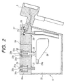
- FIG. 2 shows one embodiment of the above-described sub-tank unit 8 with respect to one ink storage chamber 25.
- Disposed in the top of the sub-tank unit 4 are an ink injection port 21 having a self-seal type valve 20, an exhaust port 23 having a self-seal type valve 22, an atmospheric communication port 24, and a valve chamber 28 that is opened and closed by an operation rod 27 and that is located in an intermediate portion of a flow passage 26 connecting the record head 5 to the ink storage chamber 25.
- the self-seal type valves 20 and 22 are made up of springs 20a and 22a, and valve bodies 20c and 22c that are pressed by the springs 20a. and 22a against openings 21a and 23a of the ink injection port 21 and the exhaust port 23 and that have operation rods 20b and 22b the upper ends of which are at the sealing time.
- a float valve 29 is pivoted at one end on a shaft 29a, and seals the exhaust port 23 when ink rises to a predetermined liquid level.
- the float valve 29 is housed in the ink storage chamber 25.
- FIG. 3 shows one embodiment of the ink replenishment unit 8 related to one ink storage chamber.
- the ink replenishment unit 8 includes an ink replenishment port 31 having a self-seal type valve 30, a suction port 33 having a self-seal type valve 32, a seal valve 35 provided on the tip of an operation rod 34, and a valve drive rod 36. These are provided in a frame F moved up and down by a drive mechanism (not shown) so as to face the ink injection port 21, the exhaust port 23, the atmospheric communication port 24, and the operation rod 27 of the sub-tank unit 4, respectively.
- the ink replenishment port 31 is connected to the cartridge holder 7 by the tube 10 and the suction port 33 is connected to the suction pump 11 by the tube 12.
- the self-seal type valves 30 and 32 are made up of springs 30a and 32a, and valve bodies 30c and 32c that are pressed by the springs 30a and 32a against valve seats 31a and 33a of the ink replenishment port 31 and the suction port 33 and that have operation rods 30b and 32b to be pushed in by the operation rods 20b and 22b of the sub-tank unit.
- the carriage 1 is moved to the non-print area and the sub-tank unit 4 is made to face the ink replenishment unit 8, then the ink replenishment unit 8 is moved down.
- the operation rods 30b and 32b of the self-seal type valves 30 and 32 of the ink replenishment unit 8 rise while pushing down the operation rods 20b and 22b of the self-seal type valves 20 and 22 of the sub-tank unit 4, the ink replenishment port 31 and the ink injection port 21 communicate with each other, the suction port 33 and the exhaust port 23 communicate with each other, the seal valve 35 seals the atmospheric communication port 24, and the valve drive rod 36 pushes down the operation rod 27 to close the valve chamber 28.
- ink replenishment unit 8 In other ink storage chambers 25, similar operation is performed and all the ink storage chambers 25 are automatically filled with ink to a predetermined level. If the ink replenishment unit 8 is moved upward at such a timing that filling the ink storage chambers 25 with ink is complete, as shown in FIG. 2, the self-seal type valves 20 and 22 of the sub-tank unit 4 and the self-seal type valves 30 and 32 of the ink replenishment unit 8 are automatically closed by the urge force of the springs 20a, 22a, 30a, and 32a, and the atmospheric communication port 24 and the valve chamber 28 are opened as the operation rod 34 and the drive rod 36 retreat.
- the record head 5 After replenishment with ink, and if necessary, the record head 5 is sealed by the cap unit 9 so that ink is forcibly discharged from the record head 5 by negative pressure generation means such as the suction pump 11 to recover destruction of the meniscus of the record head 5 caused by replenishment with ink, and thereafter the print operation is started.
- negative pressure generation means such as the suction pump 11
- the carriage 1 and the ink supply tubes 10 are separated from each other, thus the carriage 1 can move freely regardless of the number of the ink supply tubes 10, making it possible to execute print at high speed. Since ink in the ink storage chamber 25 is sufficiently degassed by negative pressure at the ink replenishing time, occurrence of bubbles during printing can be suppressed and stable print can be continued even with such an ink droplet ejection type record head that pressurizes the pressure generation chamber by a piezoelectric element, etc.
- the ink amount of the ink storage chamber 25 can be determined by adding up and calculating the amounts of ink consumed by print and suction or providing the ink storage chamber with optical liquid level detection means or float-type liquid level detection means.
- the valve chamber 28 is closed during the replenishment period.
- negative pressure may act on the ink storage chamber 25 to such an extent that the meniscus of the record head 5 can be maintained during injection of ink.
- the ink storage chamber 25 can be filled with ink with the ink storage chamber 25 maintained in a negative pressure state by means of the meniscus even if the flow passage 26 with the record head 5 is opened.
- the exhaust:port 33 when a predetermined amount of ink is injected, the exhaust:port 33 is closed.
- the float valve 29 may be placed on the ink injection port 21 side to seal the ink injection port 21 at the stage where the predetermined level is reached. In this case, after filling with ink, exhaust from the exhaust port 23 can be continued to sufficiently degas ink.
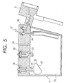
- FIG. 6 shows a second embodiment of sub-tank unit 4.
- An ink storage chamber formation member 40 and a valve unit 60 are provided as separate bodies, and the valve unit 60 is coupled to the top of the ink storage chamber formation member 40 integrally by fitting a projection 41, 41' on one side wall of the ink storage chamber formation member 40, into an engagement hole 61, 61' formed in the valve unit 60.
- the ink storage chamber formation member 40 is made up of a case 42 opened on the top and a lid 43 for covering the top, whereby an ink storage chamber 44 that can be hermetically sealed is provided.
- a float member 45 floating up by ink in the ink storage chamber 44 rotates on a support shaft 46 in response to the ink amount.
- a seal member 47 is placed on the top of the float member 45, and abuts a valve member 62 to close a suction passage communicating with a pressure reducing pump at the stage where filled ink reaches a predetermined amount.
- An ink injection port 63 for receiving ink supplied from a main tank, an ink supply port 62 for supplying ink to the record head via the valve unit 60, and an atmospheric communication port 65 are placed on the top of the ink storage chamber formation member 40.
- the valve unit 60 has a valve member 66 common to suction spaces 67, which is connected to the pressure reducing pump side and which is opened at the stage where it is connected to a replenishment unit placed on an ink supply stage. If a plurality of ink storage chambers are formed, the suction spaces 67 are formed one for each ink storage chamber 44 in a direction perpendicular to the paper plane in the figure and are made to communicate with each other so that negative pressure can be supplied from a common pressure reducing pump.
- each injection space 68 for feeding ink into the ink injection port 63 is formed separately for a respective ink storage chamber, and is provided with a valve unit 69 opened at the stage where it is connected to replenishment unit placed on ink supply stage, and the valve unit 60 is adapted for connection to replenishment unit (described later) placed on ink supply stage.
- ink supply valves 70 opened and closed each in an intermediate portion of an ink supply passage from the ink supply port 64 to the record head are placed separately in a one-to-one correspondence with the ink storage chambers.
- the atmospheric communication port 65 in the valve unit 60 can be opened and closed by an air introduction valve 71, which is housed in an air introduction space 73 having an atmospheric communication hole 72 made in the upper end. If a plurality of ink storage chambers are formed, the atmosphere introduction valves 73 are formed one for each ink storage chamber in a direction perpendicular to the paper plane in the figure.
- the ink storage chamber formation member 40 and the valve unit 60 are connected such that, as can be seen, for example, in the ink supply port 64, a pipe 77 is extended to a tubular connection part 76 pressure-inserted into an annular flexible seal member 75 disposed in a recess part 74 formed in the valve unit 60 side. Similar structure is also adopted for the ink injection port 63, as seen in FIG. 6. In the figure, numeral 80 denotes a connection port for the record head 5.
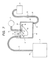
- FIG. 7 schematically shows one ink supply system for supplying ink from the ink cartridge 6 as the main tank via the sub-tank unit 4 to the record unit 5 without showing the valve unit 60 on the sub-tank unit side and the replenishment unit on the ink supply stage.
- the ink cartridge 6 forming the main tank is mounted to the cartridge holder 7 disposed, for example, on either of outer sides of the recording apparatus as described above.
- the ink cartridge 6 is connected to the ink replenishment unit 8 by the tube 10 forming the ink supply passage so as to supply ink via the ink replenishment unit 8 to the sub-tank unit 4 mounted on the carriage 1.
- the sub-tank unit 4 is connected to the record head:5 by the ink supply duct 26, and a valve 78 made up of a valve chamber and an operation rod is disposed at an intermediate portion of the ink supply duct 26. Locating an ink flow exit 6a of the ink cartridge 6 forming the main tank below the ink injection port 64 of the sub-tank unit 4 can prevent natural flow-in of ink by a siphon phenomenon is and thus ink leakage caused by an unforeseen accident. If the value 78 is closed at least when power is shut off, increasing the viscosity of ink in the ink cartridge 6 can be prevented.
- FIG. 8 shows one embodiment of a connection mechanism.
- the embodiment will be discussed by taking as an example such a connection mechanism for supplying ink to a recording apparatus that six ink storage chambers are formed independently to construct a sub-tank unit which is mounted on a single carriage.
- a replenishment unit 90 is adapted to be moved vertically by an up and down drive mechanism (described later) in the range in which it can be attached to and detached from the sub-tank unit, with a replenishment member 91 formed with vertically guiding elongated grooves 91a at left and right end parts thereof and a guide case 92 having four guide projections 92a.
- a plurality of guide ribs 93 for engagement with guide members of the sub-tank unit are formed at the bottom of the replenishment unit 90.
- the replenishment unit 90 is formed at the top with tube connection ports 94 for connection by the.tubes 10 to the ink cartridges 6 in which inks of six colors are respectively stored.
- Valve members 100 (described later) are formed in.the bottom of the replenishment unit 90 to correspond to the arrangement pitch in the sub-tank unit 4.
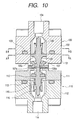
- FIGS. 9 to 11 show one embodiment of the valve member 100 of the replenishment unit 90 and one embodiment of a valve member 110 of the valve unit 60 of the sub-tank unit 4.
- the outer shell of the valve member 100 of the replenishment unit is formed by axially joining first and second cylindrical cases 101 and 102, and an O ring 103 is placed therebetween in an elastically press state to join the first and second cylindrical cases 101 and 102 in a hermetic state.
- An opening 104 made at the top in the figure communicates with the ink cartridge via the tube connection port 94 of the replenishment unit 90.
- a push rod 105 formed with a convex part 105a on the connection end face side is placed slidably in the axial direction in the axis center part of the cylindrical case 101, 102, and is always urged so that the convex part 105 of the push rod 105 projects to the connection end face side (downward in the figure) by means of a coil spring 106 placed between a flange part 105b formed on the push rod 105 and the second case 102.
- the push rod 105 is formed on the outer periphery with a taper part 105c spread upward, and in the projection state of the push rod 105 the taper part 105c is brought into elastic contact with a seal member 107 for providing sufficient hermeticity.
- a part of the seal member 107 is extended to the end face side integrally, and the end faces of the valve members are sealed by means of an extension part 107a on the end face side in a state in which the valve members are connected to each other shown in FIG. 10.
- the outer shell of the valve member 110 of the sub-tank unit is formed by axially joining first and second cylindrical cases 111 and 112, and an O ring 113 is placed therebetween in an elastically pressed state to join the first and second cylindrical cases 111 and 112 in a hermetic state.
- An opening 114 made at the bottom in the figure can communicate with the sub-tank unit side.
- a push rod 115 formed with a convex part 115a on the connection end face side is placed slidably in the axial direction in the axis center part of the cylindrical case 111, 112, and is always urged so that the convex part 115a of the push rod 115 projects to the connection end face side (upward in the figure) by means of a coil spring .116 placed between a flange part 115b formed on the push rod 115 and the second case 112.
- An annular seal member 117 is attached to the flange part 115b formed on the push rod 115 and is brought into elastic contact with an inner wall of the cylindrical case 111 by the urge force of the coil spring 116 to provide hermeticity.
- the springs 106 and 116 contained in the valve members 100 and 110 almost balance with each other in elastic pressure so that the push rods 105 and 115 can retreat evenly for reliably opening the two valve units when they are placed in a joint state as shown in FIG. 10.
- the valve member 100 can be formed with three projections 105d in the circumferential direction of the flange part 105b between the flange part 105b of the push rod 105 and the case 102 as shown in FIG. 11 (A) on the cross section taken on line A-A in FIG. 10 to providing a sufficient ink flow passage while preventing axial rocking.
- FIG. 11 (B) three or more (in the embodiment, four) fins 102a are projected radially toward the axis center of the case 102 on the upper side above the flange part 105b of the push rod 105 (cross section taken on line B-B in FIG. 10) to reliably support the push rod 105 movably in the axial direction while providing an ink flow passage.
- such a support structure is also applied to the valve member 110.
- the float member 45 moves downwardly. In this state, the carriage is moved to the ink supply stage and the valve unit 60 of the sub-tank unit is made to face the replenishment unit 90 placed on the ink supply stage as shown in FIG. 8, then the replenishment unit 90 is moved downwardly.
- the ink supply valve 70 and the air introduction valve 71 are closed as described above and the valve members 100 and 110 shown in FIG. 9 forming the valve member 69 are opened.
- the push rods 105 and 116 move relatively evenly to establish a state in which ink can flow.
- the replenishment unit moves upwardly and both are disconnected, whereby the push rods 105 and 115 forming the valve members 100 and 110 are restored to the former state by the urge force of the coil springs 106 and 116 to close the ink supply passage.
- the ink supply valve 70 and the air introduction valve 71 which are free from the depression by the replenishment unit 90, are opened to provide the ink supply passage from the ink storage chamber 44 to the record head 5 and communicate the ink storage chamber 44 with the atmosphere, enabling print with the record head.
- FIG. 12 shows another embodiment of valve unit.
- the members previously described with reference to FIGS. 9 and 10 are denoted by the same reference numerals in FIG. 12 and only the featured points will be discussed.
- a ring retention member 119 for retaining an O ring 118 so as to expose the upper face of the 0 ring is placed on the outside of a cylindrical case 111.
- valve members 100 and 110 joined the upper face of the 0 ring 118 is brought into elastic contact with a cylindrical case 101 of the.opposed valve member 100 to provide hermeticity, and push rods 105 and 115 projecting from the valve members 100 and 110 are caused to retreat to open an ink flow passage.
- a coil spring 120 is inserted between a cylindrical case 111 and a ring retention member 119 and an O ring 118 is brought into elastic contact with a cylindrical case 101 to provide hermeticity more reliably.
- valve formation members 105d and 115c are attached to the push rods 105 and 115 to provide a valve function.
- one end of a long side 130b of a trapezoidal frame 130 having a bottom is extended to form a support shaft 46, positioning pins 132 and 133 are provided at an opposite end and in the proximity of the support shaft 46, and a seal member 47 is formed on the surface.
- An opening 130a on one side of the frame 130 is sealed hermetically by a lid 135, thereby forming the float member as a hollow body.
- the frame 130 and the lid 135 are made lightweight of an easy-to-work inaterial having a comparatively small specific gravity and durability against ink, such as a synthetic resin.
- the positioning pins 132 and 133 are formed to project 1 mm or more from the lid 135 on both sides, eliminate the surface tension caused by a gap formed by the float member 45 and an inner wall of the ink storage chamber 44, and guide the float member 45 so as to reliably move following the liquid level of ink.
- valve member 62 for forming the valve in cooperation with the float member 45 is formed of a soft material, for example, soft elastomer, and is designed to reliably provide hermeticity by the seal member 47 that may be made of a hard material provided on the float member 45.
- the valve member 62 is made up of an annular fixed member 140 and a packing 141 of a trapezoid body with a through hole 141a made in the axial center line, the bottom face of the packing 141 is fitted into the fixed member, and the valve member 62 is fixed hermetically to the rear of the lid 43 of the sub-tank unit via the fixed member 140.
- a spread opening part 141b is formed in the through hole 141a on the lid side as shown in FIG. 15 (C)
- flexibility can be improved to enhance hermeticity, and the positional tolerance with the opening of the ink supply passage can be enlarged to improve workability when the sub-tank unit 4 is incorporated into the lid 43.
- a pair of reception pieces 142 for pivotally supporting the support shaft 46 of the float member 45 is formed at one end part of the lid 43, a concave part 143 for fixing the valve member 62 is formed in the center area, and a cylindrical rib 144 projecting beyond the tip of the valve member 62 is integrally formed around the concave part 143 as shown in FIG. 18.
- numeral 145 denotes an exhaust port and numeral 146 denotes an atmospheric communication port.
- the cylindrical rib 144 receives ink droplets at the ink replenishing time, prevents ink from being deposited on the valve member 62, and provides reliability of the operation as an air valve.
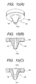
- FIGS. 17 (A) to (C) show embodiments of the float member 45, wherein each of symbols G1, G2, and G3 denotes the center of gravity of each float member, and the width in the vertical direction indicated by w1, w2, w3 denotes the move distance of each float member when the liquid level of ink rises 1 mm.
- FIG. 17 (A) shows the float member shaped like the inverse trapezoid previously described in the embodiment
- FIG. 17 (B) shows the float member shaped like a rectangle long in the length direction
- FIG. 17 (C) shows the float member shaped like a rectangle long in the width direction.
- L'>L>L stands by comparing distances L, L' , and L" that are respectively between support shafts 46, 46' , and 46" of the float members 45, 45', and 45" and buoyancy centers of gravity G1, G2, and G3.
- the float member 45" shown in FIG. 17 (C) with the shortest distance between the support shaft 46" and the buoyancy center of gravity G3 has a large cross-sectional area in the horizontal direction in contrast to that shown in FIG. 17 (B), thus the float-up amount relative to the unit liquid level rise amount is large and the accuracy of the liquid level of ink at the sealing time is high, but since the elastic contact force of the seal member 47" with the valve member 62 is small, the seal property is degraded.
- the float member 45 shown in FIG. 17 (A), which is formed like an inverse trapezoid, has large buoyancy at the sealing time and the distance L between the support shaft 46 and the center of gravity G1 is also provided reasonably, thus when the ink amount arrives at a predetermined level, the seal member 47 can be placed reliably to the valve member 62 to provide reliable sealing by large buoyancy.
- FIG. 18 shows an example of incorporating the float member 45 shown in Fig. 17 (A) into the sub-tank unit 4 to more effectively exert the characteristic of the float member 45.
- the float member 45 is attached to a pair of reception pieces 142 of the sub-tank unit 45 for rotation on the support shaft 46 so that, when the ink amount reaches a predetermined full level, a top face 45a is placed in a horizontal state and the seal member 47 comes in contact with the valve member 62.
- the float member 45 when ink reaches the predetermined full level, the float member 45 is immersed in ink up to the area where the cross section thereof in the horizontal direction is large. Accordingly, when the top face 45a is brought into the horizontal state, the float member 45 receives large buoyancy to strongly press the seal member 47 against the valve member 62, and elastically deform the valve member 62 in compression amount g, thereby delivering reliable sealing.
- the opening of the valve member is directly sealed by means of the seal member 47.
- a similar effect is produced if a flexible film 148 formed with an opening member 148a in an area not facing an opening 62a of the valve member 62 is placed so as to be made to face the opening 62a in a state in which the flexible film is normally away from the opening 62a to define a space 149 and on the other hand, the float member 45 is formed on the top face 45a with the seal member 47 at a position facing the flexible film 148, as shown in FIG. 19A.
- FIG. 20 is an exploded perspective view showing one embodiment of the attachment mechanism.
- the attachment mechanism is made up of a first mechanism 150 connected to the tube 10 and a second mechanism 160 provided to an in supply port 161 formed in an ink pack P stored in the ink cartridge 6.
- the first mechanism 150 has a fixed tube part 151 and a moving tube part 152 that are formed by mold-processing a plastic material, etc.
- the fixed tube part 151 is formed with slits to have a plurality of connection pieces 153 each having an engagement claw 153a at the tip, and the moving tube part 152 is formed with elongated holes 154 to which the engagement claws 153a are fitted; they are joined in the length direction.
- an ink flow passage formation member 155 with a through hole 155a opened at the tip thereof is fixed to and supported on a connection frame 156.
- the moving tube part 152 has a bottom part 152c comprising a through hole 152a allowing the flow passage formation member 155 on the fixed tube part side to pass therethrough, and a spring retention piece 152b projecting toward the fixed tube part side.
- a tubular seal member 157 is fixed on the opposite end side so as to cover the through hole 155a at the tip of the flow passage formation member 155 projecting from the bottom part 152c and to make the flow passage formation member 155 slidable therealong.
- the moving tube part 152 is urged to the tip side of the fixed tube part 151 by a compression spring 158 fittingly mounted between the connection frame 156 and the spring retention piece 152b.
- the tubular seal member 157 in a detachment state from the second connection part 160, is closely fitted onto the through hole 155a at the tip of the flow passage formation member 155, thereby preventing leakage of ink.
- the second connection part 160 is made up of a plastic tubular body 163 comprising a small diameter part 162 that can be inserted into the ink supply port 161 at one end and a large diameter part 163c for forming a joint part to the first connection part 150, a slider 165, and a packing 166, as shown in FIG. 22.
- the tubular body 163 is formed on the side of the small diameter part 162 with radial spring reception projections 163a and grooves 163b forming the ink flow passage extended therefrom to the small diameter part 162, as shown in FIG. 23.
- the slider 165 is accommodated in the opposite end of the tubular body 163 such that the projections 166a are engaged with holes 163d of the tubular body 163 after the slider 165 is movably inserted into the packing 166 in a state that the slider 165 is brought into abutment with the end of the compression spring 164 supported at the other end on the spring reception projections 163.
- the slider 165 is made up of a shaft part 165b inserted into a through hole 166b of the packing 166 on the center line and comprising a concave part 165a matching the shape of the tip of the flow passage formation member 155 at the tip, a bottom face part 165c coming in elastic contact with the packing 166, and a guide rib 165d formed on the outer periphery of the bottom face part 165c.
- Numeral 165e denotes a concave part for spring reception.
- the bottom face part 165c of the slider 165 is brought into elastic contact with an annular protrusion part 166b of the packing 166 by the spring 164, preventing ink from leaking from the ink pack P.
- the large diameter part 163c of the second connection part 160 provided in the ink cartridge 6 is guided by the moving tube part 152 of the first connection part to advance, and the tip of the flow passage formation member 155 is engaged with the concave part 165a of the slider 165, as shown in FIG. 24.
- the tip of the flow passage formation member 155 is formed into a conical shape and the concave part 165a of the slider 165 is also formed into a conical shape, they are guided by each other through slopes so that the axis centers easily match.
- the seal member 157 of the first connection part 150 is pressed at the tip of the packing 166 of the second connection part 16C.
- the seal member 157 of the moving tube part 152 is pressed by the packing 166 of the second connection part so that the seal member 157 retreats against the spring 158 and mutually the flow'passage formation member 155 projects.
- the through hole 155a of the flow passage formation member 155 projects to the large diameter part 163c of the second connection part and here communication is established, whereby ink in the ink pack flows into the tube along the ink flow passage indicated by symbol F.
- the seal member 157 receives the urge force of the spring 158, moves to the tip side of the flow passage formation member 155 following the movement of the ink cartridge, and seals the through hole 155a.
- the slider 165 of the second connection part 160 also receives the urge force of the spring 164, moves to the side of the packing 166 following a relative retreat of the flow passage formation member 155, and is pressed against the annular protrusion part 166b for sealing.
- a drive motor 170 is dislosed on the outside of the guide case 92, a small gear 172 is driven via a pinion joined to a drive shaft of the motor 170, and a second gear 173 is driven via a small gear disposed on the same axis as the small gear 172.
- a third gear 174 is driven via a small gearplaced on the same axis as the second gear 173 and a rotation drive force is transmitted to a drive shaft 175 fixed to the third gear 174. That is, the drive force of the motor 170 is speed-reduced in sequence manner by the first to third gears so that the drive shaft 175 can be rotationally driven.
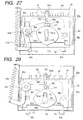
- a cam plate 176 is fixed to the drive shaft 175 and as shown in FIGS. 27 and 28, a cam follower 177 abutting the peripheral side face of the cam plate 176 is arranged rotatably by means of a support shaft 178.
- An opposite side part with respect to the support shaft 178 is pulled by a tensile spring 179 joined at one end to the guide case 92 so that the cam follower 177 is urged to always abut the peripheral side face of the cam plate 176.
- the cam follower 177 moved up and down as the cam plate 176 rotates projects also to the rear side of the paper plane in FIGS 27 and 28, and the projection part engages an elongated hole 180 formed horizontally in the replenishment member 91, causing the replenishment member 91 to reciprocate up and down.
- a horizontal maintenance member 181 is disposed on the rear side of the replenishment member 91.
- the horizontal maintenance member 181 is formed with a pair of elongated holes 181a and 181b vertically; the drive shaft 175 is inserted into one elongated hole 181a, and a support shaft 182 disposed in a parallel state with the drive shaft-175 in the guide case 92 is inserted into the other elongated hole 181b. Accordingly, the horizontal maintenance member 181 is moved in a state in which the attitude of the horizontal maintenance member 181 is corrected in the vertical direction by the drive shaft 175 and the support shaft 182.
- the drive shaft 175 rotationally drives the cam plate 176 and also provides a function of a support shaft for guiding the horizontal maintenance member 181 vertically.
- the horizontal maintenance member 181 is formed with a pair of elongated holes 181c and 181c horizontally, and a pair of protruded parts 90a and 90a are formed on the side face of the replenishment member 91 corresponding to the elongated holes 181c and 181c.
- the protruded parts 90a and 90a are inserted into the elongated holes 181c and 181c slidably. Therefore, the replenishment member 91 is supported movably in the horizontal direction with respect to the horizontal maintenance member 181.
- the replenishment member 91 is also formed with a pair of elongated holes 90b and 90b vertically, and is supported in a state in which the drive shaft 175 and the support shaft 182 pass through the elongated holes 90b and 90b.
- Each of the elongated holes 90b and 90b formed in the replenishment member 91 has such a spread part 90c that a horizontal width is enlarged to provide a predetermined allowance relative to the drive shaft 175 and the support shaft 182 in a state in which the replenishment member 91 moves downwardly toward the replenishment side unit 4.
- the spread part 90c for the support shaft 182 is substantially formed at a position out of the upper end part of the replenishment member 91, namely, on the open end side.
- the replenishment member' 91 is supported movably in the horizontal direction with respect to the horizontal maintenance member 181, and moreover can move slightly in the horizontal direction while the attitude of the replenishment member 91 is regulated by the horizontal maintenance member 181 in the range of a predetermined allowance formed between the spread parts 90c and the drive shafts 175 and the support shaft 182 only in the state in which the replenishment member 91 moves downwardly toward the sub-tank unit 4.
- Guide ribs 93 are arranged in the lower bottom part of the replenishment member 91, each being formed with slopes facing inwardly with a distance therebetween increased downwardly.
- the guide ribs 93 are placed in relation orthogonal to each other in the horizontal direction as shown in FIGS. 29 (A) and (B) to 32 (A) and (B).
- the sub-tank unit 4 is formed at corners with guide parts 189.
- the slope part 93a of the guide rib 93 abuts the guide member 189 so that the replenishment member 91 is moved horizontally while the attitude of the replenishment member 91 is regulated by the horizontal maintenance member 181 with the sub-tank 4 as the reference.
- the replenishment member 91 is aligned at a predetermined position with respect to the sub-tank unit 4 and an ink supply passage is formed.
- the elongated grooves 91a formed vertically at left and right end parts of the replenishment member 91 are formed with spread parts 91b widening in the upper parts so as to provide a predetermined allowance relative to each guide projection 92a in the state in which the replenishment member 91 moves downwardly toward the sub-tank unit 4. Therefore, the replenishment member 91 can also be aligned with the replenishment side unit 2 in a direction orthogonal to the replenishment member 91.
- each of the replenishment unit and the sub-tank unit forming the connection mechanism is provided with ink supply passages arranged in a single row in the carriage scan direction.
- ink supply passages are arranged in a single row in a direction orthogonal to the carriage scan direction or if the ink supply passages are arranged in the carriage scan direction and in the direction orthogonal to the carriage scan direction.
- the embodiment includes, similarly to the above-described arrangement, a slide plate 191 moved up and down while being guided by four guide projections 190a oriented inwardly on the guide case 92, a cam plate 192 rotationally driven by the drive motor 17.0 and train 171 to 175 previously shown in FIG. 26 to determine the movement of the slide plate 191, a pin 193, i.e.
- a cam follower coming in contact with the cam plate 192 and loosely fitted into a through hole 191a provided in the slide plate 191, a lever 195 having one end to which the pin 193 is fixed and the other end to which a spring 194 is suspended, a closing member 196, disposed opposite from the lever 195 with respect to the cam plate 192 of the slide plate 191, for pressing the air introduction valve 71, i.e. the atmospheric communication port opening and closing means, to close the same (see FIG. 6), a spring 197 attached between the closing member 196 and the slide plate 191, and a connection suction passage 197 formed in the slide plate 191.
- the slide plate 191 is formed with two regulation members 191b and 191b extended upward, and the support shaft 182 is inserted between the regulation members.
- a through hole 191d into which the drive shaft 175 is inserted, and a through hole 191c into which the support shaft 178 of the lever 195 is inserted are formed.
- the through hole 191c is elongated up and down, and the through hole 191d is formed in a similar fashion as the through hole 191c.
- the width of the through hole 191 is narrowed to such an extent that the drive shaft 175 can be passed therethrough.
- the closing member 196 is set so that the tip part thereof is positioned toward the sub-tank unit side (in the figure, downward) relative to the tip part of the connection suction passage 197 connected to the sub-tank unit side.
- the atmospheric communication port 65 is closed by the closing member 196 prior to connection of the connection suction passage 197 to the valve unit.
- the tube 12 connected to the pressure reducing pump 11 is joined to the upper end opening part of the connection suction passage 197, and a valve connection part 200 described later is provided to the lower end opening part thereof.
- FIG. 34 is a sectional view showing the valve connection part 200 in a pump connection mechanism 41 disposed on the above-mentioned ink supply stage, and a valve member 110' disposed on the sub-tank unit 4 side.
- the valve member 110' provided on the sub-tank unit adopts the same structure as the valve 100 of the two valves 100 and 110 shown in FIG. 9, and the valve 100 arranged upside down is used, and therefore a description thereof will not be given.
- valve connection part 200 is provided with a communication opening 200b that communicates with the connection suction passage 197 and that is located in an area of a bottom part 200a not opposed to a protruded part 105a of a push rod 105.
- the bottom part 200a is finished to define a plane surface coming in intimate contact with an extension part 107a of a part of a seal member 107 of the valve member 110' for reliable sealing.
- the sub-tank unit 4 when the sub-tank unit 4 is brought into an ink near end state and thus replenishment with ink becomes necessary, the sub-tank unit 4 is moved to the ink supply stage by the carriage and the attachment mechanism on the ink replenishment side is connected to the sub-tank unit 4.
- the cam plate 192 Upon the completion of docking, the cam plate 192 is rotated to move the pin 193 downwardly along the path of the cam plate 192, and move the slide plate 191 fixed thereto also downwardly.
- the slide plate 191 is guided by four guide projections 190a formed in the guide case 92, the support shaft 182 in the upper part of a guide case 190 almost between the guide projections 190a, the regulation members 191b and 191b, the drive shaft 175, and the through hole 191d, so that the slide plate 191 moves smoothly without swinging.
- the closing member 196 When the slide plate 191 thus arrives at a lower position, as shown in FIG. 35, the closing member 196 first abuts the air introduction valve 71 (see FIG. 6) of the valve unit 60 provided in the sub-tank unit 4, and at the stage where,the slide plate 191 further moves downwardly in the state, the closing member 196 presses and first closes the air introduction valve 71 against the compressed spring 197, then when the slide plate 191 further moves downwrdly, as shown in FIG. 36, the valve connection part 200 of the connection suction passage 197 communicates with the valve member 110' and communicates with the ink storage chamber 44.
- the flow passage for connecting the sub-tank unit 4 and the record head 5 is closed by the ink supply valve 70 by a member (not shown) as in the above-described embodiment.
- valve 71 of the atmospheric communication port is opened and closed in conjunction with movement of the pump connection mechanism, special valve drive means such as a solenoid becomes unnecessary.
- the atmospheric communication port opening and closing means is constructed as a vertically movable member urged by the coil spring 197.
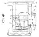
- a plate spring 201 is fixed by a fixture 202 like a cantilever beam at the lower end of the slide plate 191 and the air introduction valve 71 is operated by a free end 201a of the plate spring 201 as shown in FIG. 37 or if an L-shaped arm 204 is rotatably supported by a shaft 203 at the lower end of the slide plate 191, a horizontal part 204a is extended to the air introduction valve 71 side, and a horizontal part 204 is urged downwardly by a spring 205 through a vertical part 204b as shown in FIG. 38.
- a coil spring 206 may be provided at the upper end of the operation rod 71a of the air introduction valve 71 and on the other hand, a projection 207 may be formed in the corresponding area of the slide plate 191, so that the operation rod 71a of the air introduction valve 71 may be moved via the spring 206 by the projection 207, as shown in FIG. 39.
- the single communication opening 200b is formed in the area not opposed to the protruded part 105a of the push rod 105.
- a similar effect is produced if a plurality of fine holes 200d are formed so that the protruded part 105a of the push rod 105 can be pressed or if a slit hole 200e narrower than the diameter of the protruded part 105a is formed, as shown in FIGS. 40 and 41.
- the air introduction valve 71 of the valve unit 60 is closed earlier than the suction connection passage 197 when the ink replenishing is performed, and the air introduction valve 71 of the valve unit 60 is opened earlier than the suction connection passage 197 after the ink replenishing is completed, as in the above-described embodiment.
- the ink supply operation is not hindered.
- the ink supply valve 70 is closed, and after the expiration of a predetermined time the pressure reducing pump 11 is operated. Since this allows negative pressure to act on the ink storage chamber 44 in a state in which communication between the record head 5 and the ink storage chamber 44 is inhibited, it is possible to avoid the meniscus on the nozzle openings from being destroyed by sucking air through the nozzle openings.
- the air introduction valve 71 is opened, and if the ink storage chamber 44 becomes atmospheric pressure, then the ink supply valve 70 is opened. This makes it.possible to avoid the meniscus of the nozzle openings from being destroyed by sucking air through the nozzle openings of the record head.
- the items can also be controlled by adjusting the operation timings of the pressure reducing pump 11, the ink supply valve 70, and the air introduction valve 71.
- the ink supply valve 70 and the air introduction valve 71 are maintained open to supply ink to the record head, and the valves 69 and 66 are maintained closed.
- the ink supply valve 70 is closed to inhibit communication between the ink storage chamber 44 and the record head, thereby preventing evaporation of the ink solvent and suppressing an increase in the ink viscosity.
- the air introduction valve 71 is closed to prevent the ink solvent from volatilizing from the atmospheric communication port 65, and both the valves 69 and 66 are maintained closed.
- the air introduction valve 71 is opened so that the ink storage chamber 44 is restored to atmospheric pressure, and then the ink supply valve 70 is opened. This avoids destruction of the meniscus of the nozzle openings caused by the difference between the pressure .in the ink storage chamber 44 and the atmospheric pressure.
- the air introduction valve 71 is automatically opened when a given or more difference occurs between the pressure in the ink storage chamber 44 and the atmospheric pressure even in a state in which power supply is shut off, the ink leakage from the sub-tank 40 and the damage can be prevented.
- a carriage 210 is provided with a sub-tank unit 214 for temporarily storing yellow ink, cyan ink, magenta ink, black ink, etc., and ink cartridges 6 as main tanks are installed in a housing 212. Both of them are momentarily connected together by a reciprocating coupler 213 so that ink can be supplied from the ink cartridges 6 to the sub-tank unit 214.
- FIG. 43 shows an outline of a print mechanism and FIG. 44 shows one embodiment of the sub-tank unit 214.
- a case 214 an ink storage chamber 216 for receiving ink injected from the ink cartridge 6 through an injection needle 215 is formed, and a valve body 217 and a diaphragm 219 having an ink flow hole 218 forming a check valve mechanism in corporation with the valve body 217 are arranged in a lower area to form a second ink storage chamber 229 for supplying ink to a record head 220 while suppressing pressure change as much as possible.
- the check valve mechanism made up of the valve body 217 and the diaphragm. 219 opens the ink flow hole 218 to supply ink to the second ink storage chamber 229 if the pressure in the lower area of the diaphragm 219 is lowered.
- the diaphragm 219 moves upwardly to close the ink flow hole 218.
- a specific structure of the check valve mechanism is shown, for example, in JP-A-8-174860, etc.
- the injection needle 215 described later and the upper end of a suction passage 221 extended up and down are opened at the top of the ink storage chamber 216.
- the lower end of the suction passage 221 is formed in a non-print area of the record head 220, for example, in the proximity of the outside of nozzle openings 223 as a suction port 222.
- the nozzle openings 223 and the suction port 222 can be connected to a recovery pump 224 and a replenishment suction pump 225 described later.
- electrodes 226 and 227 for detecting the upper and lower limits of the ink liquid level are arranged in the ink storage chamber 216, and a common electrode pin 228 is arranged in the second ink storage chamber 229, so that the upper and lower limits of the ink remaining amount in the ink storage chamber 216 can be detected based on the resistance values between the electrodes 226 and 227 and.the common electrode pin 228.
- the ink cartridges 6 store inks separately so as to correspond to the sub-tank units 214, and are connected to the reciprocating couplers 213 by tubes 12.
- the reciprocating coupler 213 is provided with a rubber seal 234 hermetically attached to and detached from the injection needle 215 at the tip side of a reciprocating mechanism 233 made up of a rack 230 moving relative to the injection needle 215 projected from the sub-tank unit 214 and a pinion driven by a motor 231.
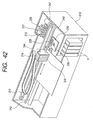
- a suction port cap 235 that can engage the suction port 222 of the sub-tank unit 214 by a drive mechanism (not shown) is fixed to the surface of a base 236, and is connected to a suction pump 225, i.e. the replenishment means, by a tube 237.
- a nozzle cap 238 connected to the recovery means 224 by a tube 239 is disposed on the base 236, and a nozzle cleaner 240 and a suction port cleaner 241 are juxtaposed to the side thereof.
- the nozzle cap 238 is made to communicate with a waste ink absorption material 246 via an exhaust pipe 239, and the recovery pump 224 is disposed on the exhaust pipe 239, so that ink can be absorbed.
- the carriage 210 can be reciprocated on a guide shaft 242 laterally extending in a frame 212, and is driven to a record position or a replenishment, recovery position through a drive belt 243 by drive means 247.
- the sub tank unit 214 is provided on a holder 244 mounted on the carriage.
- the record head 220 and the suction port 222 are exposed to the lower face of the carriage 210, and can be confronted with an ink supply position or a recovery processing position selectively by moving the carriage 210.
- the replenishment pump 225 and the recovery pump 224 are designed as follows: As shown in FIG. 45, a rotation plate P3 is fixed onto a drive shaft P2 rotatably supported on a support frame P1, a pair of rollers P4 are loosely mounted on the rotation plate P3 so that the outer peripheries thereof are partially projected outwardly of the rotation plate P3, a tube P6 is arranged along a guide frame P5, and the drive shaft P2 is rotated by drive means (not shown) to move the position where the roller P4 presses the tube P6, thereby deforming and flattening the tube P6 partially, and thus generating suction pressure.
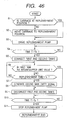
- the position of the carriage 210 is detected and whether or not the carriage is at the ink replenishment position is determined (S1). If the carriage is not at the home position (H), the carriage 210 on the guide shaft 242 is moved to the home position (H) so that the injection needle 215 of the sub-tank unit 214 is confronted with the rubber seal 234 of the reciprocating coupler 213 (S2).
- the reversible motor 231 of the reciprocating coupler 213 is started to rotating the pinion 232, so that the rubber seal 234 of the reciprocating coupler 213 is advanced in the arrow (B) direction to the needle 215 therein, thereby connecting the sub-tank unit 214, i.e. a sub tank unit, and the cartridge 6, i.e. a main tank (S5).
- the replenishment pump 225 communicating with the sub-tank unit 214 has already been in an activated state for Tb time, thus even if the rubber seal 234 is opened, replenishment with ink is started smoothly without allowing ink to flow backward into the ink cartridge 6 leading to entry of air.
- the pump 225 is driven for required time Ta, namely, the time for which ink remaining in the passage between the inside of the ink storage chamber 216 of the sub-tank unit 214 and the suction port 222 and in the needle 215 can be discharged (S10), the pump 225 is stopped. This makes the apparatus ready for record processing in a state in which clogging, etc., is prevented.
- the spout port of the pump 225 is made to communicate with the waste ink absorption material 246 by the tube 245 and if ink spray flows in or the ink amount exceeds the upper limit, ink can be absorbed in the waste ink absorption material 246.
- the ink remaining amount resulting from subtracting the consumption amount of ink consumed by ejection and recovery operations from the ink full amount of the sub-tank unit 214 detected by the electrode pin 226. is compared with the ink consumption amount required for the recovery operation. (K3), and if the remaining ink amount is greater than the amount of ink consumed by the recovery operation, a recovery operation command is given (K6).
- the pump 224 is started and negative pressure is given to the nozzle openings 223 by the nozzle cap 238 to forcibly discharge ink from the record head 220, thereby executing recovery processing.
- the carriage 210 is moved to a record position (X), (K7).
- the sub-tank unit 214 is replenished with ink from the ink cartridge 6, (K4), and it is detected whether or not the sub-tank unit has been replenished with ink until detection by the electrode pin 226 (K5). After the replenishment is completed, the above-described recovery processing is executed (K6).
- FIG. 48 shows another embodiment.
- nozzle cap means are provided separately at two locations, a replenishment position (Y) at which a sub-tank unit 214 is replenished with ink and a recovery position (Z) at which ink is forcibly discharged from nozzle openings 223.
- a first base 250 at the replenishment position (Y) is provided with a nozzle cap 251 having a closed bottom, namely, in the form of a blind-hole plug, and a suction port cap 252 made to communicate with a replenishment pump 225 by a tube
- a second base 253 is provided with a nozzle cap 254 made to communicate with a recovery pump 224 by a tube 239 and a suction port cap 255 having a closed bottom, namely, in the form of a blind-hole plug.
- the sub-tank unit 214 is replenished with ink at the replenishment position (Y), and is.subjected to the recovery processing for the nozzle openings 223 at the recoveryposition (Z) .
- a carriage 210 is stopped at the recovery position (Z), and the nozzle openings 223 and the suction port 222 are respectively sealed with the nozzle cap 254 and the suction port cap 255.
- the nozzle openings 223 are completely sealed with the cap 251 isolated from the outside, and therefore it is possible to more positively prevent dry on the nozzle openings 223 and back-flow of air during replenishing with ink.
- FIG. 49 shows the ink replenishment operation suitable for the recording apparatus of the embodiment.
- a recovery command generated by an operator or generated based on a predetermined sequence
- the operation for this is similar to that at steps S1 and S2 previously described with reference to FIG. 46.
- the suction port 222 is brought into intimate contact with the suction port cap 252 (L3), the replenishment pump 225 is operated (L4), if a predetermined time (Tb) has elapsed (L5), then a reversible motor 232 is operated to engage a rubber sheet 234 with a needle 215 in a state in which the pressure reduction state in the sub-tank unit 214 reaches a predetermined level, thereby connecting the sub-tank unit 214 and an ink cartridge 6 (L6).
- the sub-tank unit 214 is replenished with ink and if a state in which the sub-tank unit 214 is replenished sufficiently with sufficient ink is detected by the upper limit detecting electrode pin 226 (L7), the rubber seal 234 is retreated to disconnecting the sub-tank unit 214 from the ink cartridge 6 (L8).
- the replenishment pump 225 is stopped (L10), the suction port 222 is detached from the suction port cap 252 (L11), the sub-tank unit is moved to the recovery position (Z) (L12), and the nozzle openings 223 are brought into intimate contact with the nozzle cap 254 (L13).
- the recovery pump (Pr) 224 is operated to perform recovery processing for the nozzle .openings 223 over required recovery time (TR) corresponding to the suction time (L14), and the recovery operation is completed.
- TR required recovery time
- X record position
- the'operation shown in FIG. 50 is executed. That is, before the recovery operation of the sub-tank unit 214 is performed, ink is preliminarily discharged to the minimum amount (lower limit value), and then the sub-tank unit 214 is replenished with ink to the maximum amount (upper limit value) from the ink cartridge 6, and thereafter the recovery operation is performed.
- the carriage 210 is moved to the recovery position (Z) in response to a recovery signal (M1), the suction port 222 is brought into intimate contact with the suction port cap (M2), the recovery pump 224 is operated (M3), and ink is discharged from the sub-tank unit 214 until detection of the lower limit value (M4).
- the sub-tank unit 214 is moved to the replenishment position (Y) and is replenished with ink to the upper limit value from the ink cartridge 6, and then a recovery process similar to that described above is executed.
- the remaining ink in the sub-tank unit 214 is sufficiently discharged, degassed ink is supplied in a large amount from the ink cartridge. 6, and therefore recovery processing can be made reliable to assure quality of subsequent print.
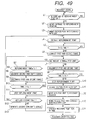
- the recovery operation shown in FIG. 51 is a processing to be executed in a case where the ink droplet ejection capability of the record head 220 cannot be sufficiently recovered by normal recovery processing.
- N3 If the number of print lines is smaller than C1, it is detected whether or not the number of print lines after the further preceding recovery operation is smaller than C2 (N3). If the number of print lines is not smaller than C2, recovery operation (2), namely, the operation with the recovery pump operation time TR at step L14 in FIG. 49 be prolonged is executed (N4).
- recovery operation (3) namely, the operation shown in FIG. 50 is executed (N5).
- the number of print lines C1 is 60 and C2 is 100, but the number of print sheets, the number of print characters, the print time, etc., can also be applied as C1 and C2 in place of the number of print lines.
- the carriage 210 is stopped at the recovery position (Z) and the nozzle openings 223 are sealed with the nozzle cap 251 and the suction port 222 is sealed with the suction port cap 252.
- record is stopped, not only the nozzle openings 223 of the record head 220, but also the suction port 222 is capped. Accordingly, it is possible to prevent not only drying through the suction port 222, but also ink leakage occurring if the recording apparatus falls down.
- the nozzle openings 223 are sealed with the nozzle cap 251 having a closed:bottom, namely, in the form of a blind-hole plug, and during the recovery operation, the suction port 222 is covered with the cap 255 having a closed bottom, namely, in the form of a blind-hole plug. Accordingly, it is possible to reliably prevent drying of the nozzle openings 223 during the replenishment operation and the recovery operation, and also it is possible to prevent unnecessary air from flowing into the ink storage chamber 216 during the recovery operation.
- the ink in the storage chamber may be brought into a degassed state to some, but not sufficient, extent. For example, it may be difficult to obtain a degassed degree to such an extent that air bubbles entering the record head are dissolved in ink.
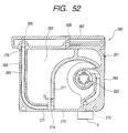
- FIGS. 52 and 53 show another embodiment of sub-tank unit for solving such a problem.
- a sub-tank unit 260 is formed with an ink storage section 262 such that an unillustrated laminate film in which a metal layer extremely low in water vapor permeability and gas permeability is laminated on a polymer film is welded and attached to an opening in each of the sides of a casing 261 adopting a frame structure molded of a plastic material, etc.
- Negative pressure generation means 263 is disposed on a side of one side wall 264 to transport standby ink WI stored in the ink storage section 262 to the record head 5.
- Ink flow passage means 266 is formed on a side of the other side wall 265.
- a ventilation hole 268 is formed in a top wall 267 of the casing 261, and a replenishment port 269 into which ink flows from the ink cartridge 6, i.e. the main tank, is formed to communicate with the upper end of the ink flow passage means 266.
- the record head 5 is fixed to a bottom wall 270 of the casing 261.
- the negative pressure generation means 263 is separated from the ink storage section 262 by a partition wall 271, and designed so that standby ink WI or replenishment inkNI supplied from a flow-in port 274 in the bottom of the partition wall 271 is supplied through an ink passage 275 to the record head 5, using a valve 273 pulsated against a spring 272 as shown in FIG. 54 in response to pressure change produced by the print operation, etc., of the record head 5 ejecting ink droplets by drive means (not shown), such as piezoelectric means.
- the ink flow passage means 266, which is bent roughly like an L letter, includes an introduction port 276 communicating with the replenishment port 269, a flow passage along the side wall 265, a traverse flow passage along the bottom wall 270 continuing the side wall 265, and a flow-out port 277 on the bottom wall 270 side, which is located close to the flow-in port 274 of the negative pressure generation means 263 with a given gap G.
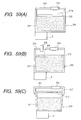
- FIG. 55 shows an ink replenishment system for the sub-tank unit 260.
- a main tank 280 and the sub-tank unit 260 are provided with a first connector 281 and a second connector 282, respectively, that can be connected to each other. By connecting the first and second connectors 281 and 282 to each other, ink can be supplied from the main tank 280 to the sub-tank unit 260.
- standby ink WI in the ink storage section 262 of the sub-tank unit 260 is urged by the valve 273 pulsated against the spring 272 of the negative pressure generation means 263 to be transported from the flow-in port 274 to the negative pressure generation means 263, passes through the negative pressure generation means 263, and is supplied to the record head 5 through the ink passage 275 for printing.
- the ventilation hole 268 is made to communicate with a suction pump 283 so that pressure in the space of an upper part 262a of the ink storage section 262 is reduced.
- replenishment ink NI in the main tank 280 is allowed to flow into the introduction port 276 of the ink flow passage means 266 via the connectors 281 and 282 from the replenishment port 269 and is supplied to the ink storage section 262 through the flow-out port 277.
- the flow passage configuration shown in FIG. 55 is also formed, the nozzle openings are sealed with a cap 284, and a suction pump 285 is operated. With this process, ink is forcibly discharged from the record head into the cap 284 and is stored in a waste ink tank 286.
- replenishment ink NI having a high degassed rate stored in the main tank 280 flows in taking precedence over standby ink WI in the ink storage section 262.
- the ink flow-out port 277 is offset so as to have the given gap G from the flow-in port 274.
- ink passage wall 286 makes it possible to more reliably remove air bubbles in ink.
- ink having a high degassed rate is high in capability of allowing air bubbles to be dissolved, and therefore air bubbles entering the record head 5 are allowed to be dissolved into ink, lowering of applied pressure for ejecting ink droplets is minimized, and ink droplets are ejected stably.
- the electrode pin is arranged in the ink storage chamber to correspond to the ink-full liquid level so as to detect a state in which the ink storage chamber has been replenished with a predetermined amount of ink based on electrical resistance.
- the state may be detected based on pressure change in the ink storage chamber.
- FIG. 56 shows an embodiment of a detection mechanism suitable for detecting an ink-full state in the ink storage chamber, or detecting whether or not the ink cartridge 6 is attached.
- a main body 291 molded of a synthetic resin is formed with an ink flow passage 292 from side to side in the figure.
- the main body 291 is formed almost at the center with a guide projection 293, and a coil spring 294 is disposed surrounding the guide projection 293.
- a displacement member 295 molded of a flexible material is arranged above the main body 291 to seal an opening face in such a manner that the peripheral edge thereof is fixed, for example, by ultrasonic welding, etc.
- the member.295 forms a part of the ink flow passage 292 on the top side of the main body 291.
- a resin plate 296 is adhered onto the lower face of the displacement member 295, and an end of a spring 294 abuts almost the center of the resin plate 296 to constantly urge the displacement member 295 upward.
- a reflection plate 297 formed of a material excellent in close contact property, such as rubber, with a white surface is adhered onto the surface of the displacement member 295.
- a light sensor unit 298 forming displacement detection means for the displacement member 295 is disposed so as to face the reflection plate 297.
- the light sensor unit 298 is constructed such that a light emitting element 298a and a light receiving element 298b are disposed at positions where a light passage is formed when the displacement member 295 abuts the projection 293. Therefore, an electric signal from the light reception element 298b is turned off in a state in which the reflection plate 297 is in close contact with the unit 298, and the light reception element 298b senses light to provide an on-output in a state in which the reflection plate 297 is away from the unit 298.
- FIGS. 57 and 58 show another embodiment of an attachment state detection unit formed of pressure detection means.
- a main body 300 is formed with an ink flow passage 302 forming a part of an ink supply path from the ink cartridge 6 to the sub-tank unit 4 in the length direction of the main body 300.
- the ink flow passage 302 is formed in a bottom section with guide grooves 300a to 300d along the length direction, and a plate spring 303 is arranged in the guide grooves 300a to 300.
- the plate spring 303 is made up of a plate-like body 303a and four legs 303b to 303e extended integrally from the plate-like body 303a. The ends of the legs 303b to 303e are bent in a one-plane direction of the plate-like body 303a.
- the tips of the legs 303b to 303e are assembled as a so-called four-leg state so that they are fitted into the guide grooves 300a to 300d.
- a displacement member molded of a flexible material so as to wrap the upper face of the plate-like body 303a is attached, for example, by ultrasonic welding, etc. so as to seal the upper face of the main body 300.
- the displacement member forms a part of the ink flow passage 302 on the top side of the main body 300. Since the plate spring 303 is assembled as the four-leg state, the ink flow passage 302 can be formed between the legs 303b to 303e.
- a film member having a high reflection factor for example, an aluminum laminate film, is preferably used.
- the displacement member is formed of a transparent film member, for example, without using the aluminum laminate film, and the plate-like body 303a forming a part of the spring member is provided with a reflection function.
- the above-described light sensor unit 298 is arranged so as to come in close contact with the displacement member covering the upper face of the plate-like body 303a.
- attachment state detection units shown in FIGS. 56 to 58 will be discussed by taking the detection unit shown in FIG. 56 as an example.
- the attachment state detection unit is connected so that the flow passage 292 forms a part of the flow passage from the ink cartridge 6 to ink replenishment unit.
- the strength of the spring 294 is set to such an extent that the spring pushes up the displacement member 295 in a state in which an ink cartridge is attached and ink flows into the ink storage chamber of the sub-tank unit and that the spring can be contracted upon direct reception of a suction force of the pressure reducing pump 11.
- FIG. 59 shows other embodiments for detecting the ink amount in the ink storage chamber.
- a float 312 may be housed movably in an ink storage chamber 311 of a sub-tank unit 310 provided with the record head 5 in a lower part, and means (contact 314 in this embodiment) for detecting a state in which the float 312 has arrived at a predetermined position due to fully filled ink may be provided in an upper part of the ink storage chamber 311 (in the embodiment, in a lid 313 of the sub-tank unit 310), so that the contacts 314 may be electrically connected to each other by a conductive layer 312a on the float 312.
- the numbers of ink droplets ejected for print and the amounts of ink sucked by the recovery operation may be added up by calculation means, etc., for estimation.
- the ink supply amount is calculated, and the flow quantity of ink supplied depending on the ink level in the ink storage chamber 311 can also be adjusted by controlling the number of revolutions of the replenishment pump.
- a filter member 316 is disposed in an area of the float 312 facing an ink injection port 315, as shown in FIG. (B), for catching foreign materials such as air bubbles contained in supplied ink.
- a float guide part 317 is provided in an upper area to regulate the float 312 so that the float 312 can be moved only up and down.
- the sub-tank unit has an ink injection port and an exhaust port communicating with an ink storage chamber via self-seal type valve means, and a valve mechanism for opening and closing the ink injection port or the exhaust port based on a liquid level of ink, and ink is supplied to the ink storage chamber by negative pressure produced by sucking air through the exhaust port. Therefore, the ink storage chamber can be forcibly replenished with a predetermined amount of ink for a short time period regardless of pressure in the ink storage chamber. Further, ink is degassed as much as possible by filling ink under reduced pressure, so that stable print can be executed.
- all ink storage chambers can be automatically filled with degassed ink to a predetermined level by operating a common suction pump by forming the ink storage chambers of the same structure.
Abstract

Description
- an ink injection port and an exhaust port communicating with an ink storage chamber through self-seal type valve means; and
- a valve mechanism for opening and closing the ink injection port or the exhaust port based on a liquid level of ink;
wherein said sub-tank unit includes an atmospheric communication port, and said ink replenishment unit includes a valve for sealing the atmospheric communication port.
wherein an ink replenishment unit for replenishing said sub-tank unit with ink from the main tank by reducing pressure in the ink storage chamber by negative pressure generation means is provided.
wherein first and second ink seal means opened if the first and second connection parts are connected to each other are provided.
in 66, further comprising a float that stops ink replenishment at a stage at which the ink storage chamber is replenished with ink up to a predetermined value of ink amount.
in 67, wherein at least a part of the float is formed of an electric conductive material, and a move-up of the float is detected electrically.
in 68, wherein the ink storage chamber and the record are communicated with each other through backflow prevention means for enabling ink to flow into the record head from the ink storage chamber.
- detected, and the recovery operation is carried out at least once or more as long as ink exists.
Claims (13)
- An ink jet recording apparatus comprising:wherein an ink storage chamber and the record head of said sub-tank unit are connected through backflow prevention means for enabling ink to flow into the record head from the ink storage chamber, anda sub-tank unit provided with a record head; anda main tank capable of replenishing said sub-tank unit with ink,
wherein an ink replenishment unit for replenishing said sub-tank unit with ink from the main tank by reducing pressure in the ink storage chamber by negative pressure generation means is provided. - The ink jet recording apparatus as claimed in claim 1, wherein a carriage to which said sub-tank unit is attached is moved to a record area, an ink replenishment area, and a recovery position for recovering an ink droplet ejection capability.
- The ink jet recording apparatus as claimed in claim 2, wherein the ink replenishment area and the recovery position are the same area.
- The ink yet recording apparatus as claimed in claim 2, wherein the ink replenishment area is more distant from the record area than the recovery position.
- The ink jet recording apparatus as claimed in claim 2 or 3, wherein said sub-tank unit is allowed to communicate with said main tank in the ink replenishment area and at the recovery position.
- An ink jet recording apparatus as claimed in claim 1, comprising:wherein first and second connection parts for forming an ink flow passage between said sub-tank unit and the main tank are arranged in the conduit, anda sub-tank unit, mounted on a carriage, for supplying ink to an ink yet recording head, andan ink replenishment unit that is connected to a main tank installed in a housing by a conduit and that is connectable to or disconnectable from said sub-tank unit,
wherein first and second ink seal means opened if the first and second connection parts are connected to each other are provided. - The ink jet recording apparatus as claimed in claim 6, wherein the first ink seal means is designed so that a hollow ink flow passage member is slidably inserted into a first seal hole of a first seal body, and that an ink small hole opened in the ink flow passage member is exposed from the first seal body to open the ink flow passage only when the first connection part is connected to the second connection part.
- The ink jet recording apparatus as claimed in claim 6 wherein the second ink seal means includes a second seal body and a slide shaft having a shaft part inserted slidably into a second seal hole of the second seal body, and the shaft part is projected from the second seal hole to open the ink flow passage only when the second connection part is connected to the first connection part.
- The ink jet recording apparatus as claimed in claim 7, wherein when the first and second connection parts are connected, the shaft part of the slide shaft is urged by the ink flow passage member to open the ink flow passage.
- The ink yet recording apparatus as claimed in claim 9, wherein the ink flow passage member is formed with a conical convex part, and the shaft part of the slide shaft is formed with a conical concave part engaging the conical convex part.
- The ink jet recording apparatus as claimed in claim 1, further comprising pressure detection means, arranged in a flow passage from for communication from said sub-tank unit to the negative pressure generation means, for detecting a predetermined or more pressure drop, wherein ink replenishment completion is detected based on a signal of the pressure detection means.
- The ink jet recording apparatus as claimed in claim 1, further comprising pressure detection means connected to a flow passage between the main tank and said sub-tank unit, for generating electric output upon detection of a predetermined or more pressure drop in the flow passage, wherein an attachment state of the main tank is detected based on the electric output of the pressure detection means.
- The ink jet recording apparatus as claimed in claim 11 or 12, wherein the pressure detection means includes a flexible displacement member that forms a part of the flow passage and that is displaceable in association with pressure change in the flow passage, a spring member, added to the displacement member, for urging the displacement member in a direction opposite to a direction in which the displacement member is displaced in association with the pressure drop in the flow passage, and displacement detection means for detecting displacement of the displacement member.
Applications Claiming Priority (20)
| Application Number | Priority Date | Filing Date | Title |
|---|---|---|---|
| JP4631598 | 1998-02-13 | ||
| JP4631598A JPH11227220A (en) | 1998-02-13 | 1998-02-13 | Ink jet recorder |
| JP5907898 | 1998-02-25 | ||
| JP05907898A JP3478116B2 (en) | 1998-02-25 | 1998-02-25 | Ink jet recording apparatus, method of using the same, and ink tank thereof |
| JP17534198A JP3478127B2 (en) | 1998-06-09 | 1998-06-09 | Ink jet recording apparatus and ink ejection recovery method thereof |
| JP17534198 | 1998-06-09 | ||
| JP20037798 | 1998-07-15 | ||
| JP20037798 | 1998-07-15 | ||
| JP22113798 | 1998-07-22 | ||
| JP22113798A JP2000037879A (en) | 1998-07-22 | 1998-07-22 | Ink tank coupler for ink jet recorder |
| JP11006600A JP2000203049A (en) | 1999-01-13 | 1999-01-13 | Ink jet recorder |
| JP660099 | 1999-01-13 | ||
| JP1314199A JP3053017B1 (en) | 1999-01-21 | 1999-01-21 | Method and apparatus for detecting completion of ink filling in sub tank in recording apparatus |
| JP1314199 | 1999-01-21 | ||
| JP1314299A JP3233215B2 (en) | 1999-01-21 | 1999-01-21 | Ink jet recording device |
| JP1314299 | 1999-01-21 | ||
| JP2329899 | 1999-01-29 | ||
| JP2329899A JP3307601B2 (en) | 1999-01-29 | 1999-01-29 | INK JET RECORDING APPARATUS AND SUB-TANK DEPRESSION CONTROL METHOD IN THE APPARATUS |
| EP02020092A EP1281526B1 (en) | 1998-02-13 | 1999-02-12 | Ink jet droplet ejection capability recovery method |
| EP99902890A EP1055520B1 (en) | 1998-02-13 | 1999-02-12 | Ink jet recorder, sub-tank unit suitable therefor, and method of recovering ink droplet discharging capability |
Related Parent Applications (3)
| Application Number | Title | Priority Date | Filing Date |
|---|---|---|---|
| EP02020092A Division EP1281526B1 (en) | 1998-02-13 | 1999-02-12 | Ink jet droplet ejection capability recovery method |
| EP99902890.5 Division | 1999-02-12 | ||
| EP02020092.9 Division | 2002-09-06 |
Publications (2)
| Publication Number | Publication Date |
|---|---|
| EP1604832A2 true EP1604832A2 (en) | 2005-12-14 |
| EP1604832A3 EP1604832A3 (en) | 2006-02-22 |
Family
ID=27576529
Family Applications (3)
| Application Number | Title | Priority Date | Filing Date |
|---|---|---|---|
| EP99902890A Expired - Lifetime EP1055520B1 (en) | 1998-02-13 | 1999-02-12 | Ink jet recorder, sub-tank unit suitable therefor, and method of recovering ink droplet discharging capability |
| EP05014453A Withdrawn EP1604832A3 (en) | 1998-02-13 | 1999-02-12 | Print head with sub-tank unit connected via a back flow prevention valve |
| EP02020092A Expired - Lifetime EP1281526B1 (en) | 1998-02-13 | 1999-02-12 | Ink jet droplet ejection capability recovery method |
Family Applications Before (1)
| Application Number | Title | Priority Date | Filing Date |
|---|---|---|---|
| EP99902890A Expired - Lifetime EP1055520B1 (en) | 1998-02-13 | 1999-02-12 | Ink jet recorder, sub-tank unit suitable therefor, and method of recovering ink droplet discharging capability |
Family Applications After (1)
| Application Number | Title | Priority Date | Filing Date |
|---|---|---|---|
| EP02020092A Expired - Lifetime EP1281526B1 (en) | 1998-02-13 | 1999-02-12 | Ink jet droplet ejection capability recovery method |
Country Status (4)
| Country | Link |
|---|---|
| US (1) | US6390611B1 (en) |
| EP (3) | EP1055520B1 (en) |
| DE (2) | DE69911744T2 (en) |
| WO (1) | WO1999041083A1 (en) |
Cited By (6)
| Publication number | Priority date | Publication date | Assignee | Title |
|---|---|---|---|---|
| EP2110249A1 (en) * | 2008-04-16 | 2009-10-21 | Mimaki Engineering Co., Ltd. | Ink supply device for inkjet printer |
| EP2110250A1 (en) * | 2008-04-18 | 2009-10-21 | Mimaki Engineering Co., Ltd. | Ink replenisher and inkjet printer equipped with the ink replenisher |
| CN102555499A (en) * | 2010-12-06 | 2012-07-11 | 株式会社理光 | Image forming apparatus |
| CN102806772A (en) * | 2008-11-14 | 2012-12-05 | 精工爱普生株式会社 | Fluid storage container |
| CN103342052A (en) * | 2013-07-24 | 2013-10-09 | 冼均祥 | Ink cartridge capable of detecting state of ink in time with reed switch and detection method |
| WO2020122880A1 (en) * | 2018-12-11 | 2020-06-18 | Hewlett-Packard Development Company, L.P. | Spittoon cartridge for a printing device |
Families Citing this family (105)
| Publication number | Priority date | Publication date | Assignee | Title |
|---|---|---|---|---|
| JP3582592B2 (en) * | 2001-04-03 | 2004-10-27 | セイコーエプソン株式会社 | Ink cartridge and inkjet recording device |
| JPH08174860A (en) * | 1994-10-26 | 1996-07-09 | Seiko Epson Corp | Ink cartridge for ink jet printer |
| DE69733176T2 (en) | 1996-02-21 | 2006-02-16 | Seiko Epson Corp. | INK CARTRIDGE |
| JP4141523B2 (en) | 1997-03-19 | 2008-08-27 | セイコーエプソン株式会社 | Ink supply flow path valve device |
| WO1999041083A1 (en) | 1998-02-13 | 1999-08-19 | Seiko Epson Corporation | Ink jet recorder, sub-tank unit suitable therefor, and method of recovering ink droplet discharging capability |
| DE69943417D1 (en) * | 1998-07-15 | 2011-06-16 | Seiko Epson Corp | Ink supply unit |
| JP3617395B2 (en) * | 1999-12-06 | 2005-02-02 | セイコーエプソン株式会社 | Inkjet recording device |
| DE60044020D1 (en) | 1999-11-05 | 2010-04-29 | Seiko Epson Corp | RECORDING DEVICE OF THE INK JET TYPE AND METHOD OF INK SUPPLYING THE UNDER TANK USING THE SAME DEVICE AND METHOD FOR CONTROLLING THE AMOUNT OF INK OF THE UNDER TANK BY MEANS OF THE SAME DEVICE |
| KR100388332B1 (en) | 2000-02-16 | 2003-06-25 | 세이코 엡슨 가부시키가이샤 | Ink cartridge for ink jet recording device, connection unit and ink jet recording device |
| MY131891A (en) | 2000-05-18 | 2007-09-28 | Seiko Epson Corp | Mounting structure, module, and liquid container |
| DE60137839D1 (en) | 2000-05-18 | 2009-04-16 | Seiko Epson Corp | METHOD FOR DETECTION OF INK CONSUMPTION AND INK RADIATION RECORDING DEVICE |
| PT1164021E (en) | 2000-06-15 | 2006-08-31 | Seiko Epson Corp | LIQUID CHARGING PROCESS, LIQUID CONTAINER AND RESPECTIVE MANUFACTURING PROCESS |
| CN100564040C (en) * | 2000-07-07 | 2009-12-02 | 精工爱普生株式会社 | Liquid container, ink jet recording device, be used to control this ink jet recording device apparatus and method, be used for the apparatus and method of tracer liquid consumption state |
| JP3832225B2 (en) | 2000-10-17 | 2006-10-11 | 富士ゼロックス株式会社 | Ink supply device, ink jet recording device, and ink supply method |
| EP1481807B2 (en) * | 2000-10-20 | 2010-11-10 | Seiko Epson Corporation | Ink jet recording device and ink cartridge |
| ATE492400T1 (en) * | 2000-10-20 | 2011-01-15 | Seiko Epson Corp | INK CARTRIDGE FOR INKJET RECORDING DEVICE |
| CA2359434C (en) * | 2000-10-20 | 2005-05-03 | Seiko Epson Corporation | Ink-jet recording device and ink cartridge |
| GB2368557A (en) * | 2000-11-03 | 2002-05-08 | Opportunity Europ Limimted | Ink cartridge including a float valve disposed in the ink outlet chamber thereof |
| US6508545B2 (en) * | 2000-12-22 | 2003-01-21 | Hewlett-Packard Company | Apparatus for providing ink to an ink jet print head |
| US6883905B2 (en) | 2001-02-09 | 2005-04-26 | Seiko Epson Corporation | Ink jet recording apparatus, control and ink replenishing method executed in the same, ink supply system incorporated in the same, and method of managing ink amount supplied by the system |
| CN101177069B (en) * | 2001-02-09 | 2012-06-13 | 精工爱普生株式会社 | Ink supply system and method of managing ink amount supplied by the system |
| ATE367270T1 (en) | 2001-05-17 | 2007-08-15 | Seiko Epson Corp | INK CARTRIDGE AND PRODUCTION METHOD OF AN INK CARTRIDGE |
| JP2003034042A (en) * | 2001-05-17 | 2003-02-04 | Seiko Epson Corp | Ink cartridge |
| US6715865B2 (en) * | 2001-07-09 | 2004-04-06 | Canon Kabushiki Kaisha | Liquid jet recording head packing method, liquid jet recording head and liquid jet recording apparatus |
| EP1445105B1 (en) | 2001-11-12 | 2010-01-13 | Seiko Epson Corporation | Liquid injector |
| US7147310B2 (en) * | 2002-01-30 | 2006-12-12 | Hewlett-Packard Development Company, L.P. | Printing-fluid container |
| JP2003291367A (en) | 2002-04-02 | 2003-10-14 | Sony Corp | Device for displaying remaining amount of liquid |
| ATE434740T1 (en) * | 2002-04-12 | 2009-07-15 | Seiko Epson Corp | VALVE ARRANGEMENT |
| US6957882B2 (en) | 2002-05-23 | 2005-10-25 | Agfa Gevaert N. V. | Ink tank for feeding a shuttling inkjet printing head |
| EP1366908A1 (en) * | 2002-05-23 | 2003-12-03 | Agfa-Gevaert N.V. | Ink tank for feeding a shuttling inkjet printing head |
| ATE446196T1 (en) * | 2002-08-16 | 2009-11-15 | Oce Tech Bv | INK SUPPLY DEVICE FOR AN INKJET PRINTER |
| JP3991853B2 (en) * | 2002-09-12 | 2007-10-17 | セイコーエプソン株式会社 | ink cartridge |
| CA2506479A1 (en) * | 2002-11-18 | 2004-06-03 | Dynamic Cassette International Ltd. | An ink cartridge for a printer, a method of assembling an ink cartridge for a printer, and a filter assembly for an ink cartridge |
| JP2004276450A (en) * | 2003-03-17 | 2004-10-07 | Walbro Japan Inc | Inkjet recorder and ink fluid passage structure |
| JP2005053212A (en) * | 2003-07-18 | 2005-03-03 | Seiko Epson Corp | Liquid container |
| JP4461728B2 (en) * | 2003-07-29 | 2010-05-12 | ブラザー工業株式会社 | Inkjet recording apparatus and ink supply apparatus |
| US6935731B2 (en) | 2003-09-10 | 2005-08-30 | Eastman Kodak Company | Ink jet print system including print cartridge |
| JP2005081775A (en) * | 2003-09-10 | 2005-03-31 | Fuji Photo Film Co Ltd | Inkjet recording head assembly and inkjet recording device |
| TWI246465B (en) | 2003-09-30 | 2006-01-01 | Brother Ind Ltd | Ink cartridge and ink-jet printer |
| US7303271B2 (en) | 2003-10-24 | 2007-12-04 | Brother Kogyo Kabushiki Kaisha | Ink jet printer |
| JP4049084B2 (en) * | 2003-11-07 | 2008-02-20 | セイコーエプソン株式会社 | Fluid control valve and droplet discharge device |
| US7334888B2 (en) * | 2003-11-25 | 2008-02-26 | Brother Kogyo Kabushiki Kaisha | Ink cartridge |
| US7384136B2 (en) * | 2003-11-25 | 2008-06-10 | Brother Kogyo Kabushiki Kaisha | Ink cartridge |
| JP4492144B2 (en) | 2003-12-08 | 2010-06-30 | ブラザー工業株式会社 | Inkjet recording device |
| US7192126B2 (en) * | 2004-01-06 | 2007-03-20 | Fuji Xerox Co., Ltd. | Systems, methods and structure for maximizing efficiency of refillable fluid ejection head |
| JP4496806B2 (en) * | 2004-03-04 | 2010-07-07 | ブラザー工業株式会社 | Inkjet recording device |
| US7399070B2 (en) * | 2004-03-09 | 2008-07-15 | Brother Kogyo Kabushiki Kaisha | Ink jet printer |
| US20050219281A1 (en) | 2004-03-24 | 2005-10-06 | Takeo Seino | Attachment and liquid supplying |
| US20080259137A1 (en) * | 2004-05-13 | 2008-10-23 | Paul Geldenhuys | Ink Supply System for a Printer |
| US7281785B2 (en) * | 2004-09-17 | 2007-10-16 | Fujifilm Dimatix, Inc. | Fluid handling in droplet deposition systems |
| US7278493B2 (en) * | 2005-03-21 | 2007-10-09 | Baker Hughes Incorporated | Auto entry guide |
| JP4725265B2 (en) * | 2005-03-31 | 2011-07-13 | ブラザー工業株式会社 | Inkjet recording device |
| JP4725182B2 (en) | 2005-04-28 | 2011-07-13 | セイコーエプソン株式会社 | Method for manufacturing liquid supply system and liquid supply system |
| DE102005020488A1 (en) * | 2005-04-29 | 2006-11-09 | Büstgens, Burkhard, Dr.-Ing. | Ink supply for printheads |
| US20070166202A1 (en) * | 2006-01-16 | 2007-07-19 | Hitotoshi Kimura | Liquid container |
| JP4942163B2 (en) * | 2006-08-03 | 2012-05-30 | キヤノン株式会社 | Ink storage container |
| TWI415689B (en) * | 2006-08-17 | 2013-11-21 | Semiconductor Energy Lab | Film forming method, discharging droplet method and droplet discharging device |
| JP4284556B2 (en) * | 2006-10-31 | 2009-06-24 | ブラザー工業株式会社 | Ink supply apparatus, ink cartridge, and inkjet image recording apparatus |
| JP2008162208A (en) * | 2006-12-29 | 2008-07-17 | Brother Ind Ltd | Inkjet recorder |
| JP4882742B2 (en) * | 2006-12-29 | 2012-02-22 | ブラザー工業株式会社 | Liquid ejection device |
| JP2008162214A (en) * | 2006-12-29 | 2008-07-17 | Brother Ind Ltd | Liquid ejector |
| US20080218566A1 (en) * | 2007-03-07 | 2008-09-11 | Malik Craig L | Metallized print head container and method |
| ES2307428B1 (en) * | 2007-05-09 | 2009-10-02 | Jseus Francisco Barberan Latorre | INK FEEDING SYSTEM FOR PRINTERS. |
| US7874660B2 (en) * | 2007-10-10 | 2011-01-25 | Hewlett-Packard Development Company, L.P. | Closure and connector for a supply container |
| US8141999B2 (en) * | 2007-11-30 | 2012-03-27 | Brother Kogyo Kabushiki Kaisha | Valve mechanisms and ink cartridges |
| US7819515B2 (en) * | 2008-03-03 | 2010-10-26 | Silverbrook Research Pty Ltd | Printer comprising priming system with feedback control of priming pump |
| JP5127600B2 (en) * | 2008-07-03 | 2013-01-23 | 理想科学工業株式会社 | Connection mechanism and ink supply apparatus provided with the same |
| JP5047916B2 (en) * | 2008-09-29 | 2012-10-10 | 株式会社ミマキエンジニアリング | Ink supply device for ink jet printer and reverse flow blocking device |
| AU2008365367B2 (en) * | 2008-12-19 | 2011-12-22 | Silverbrook Research Pty Ltd | Ink manifold with multiple conduit shut off valve |
| US20110025761A1 (en) | 2009-07-31 | 2011-02-03 | Silverbrook Research Pty Ltd | Printing system with multiple ink accumulators |
| CN101992602B (en) * | 2009-08-24 | 2012-09-19 | 珠海中润靖杰打印机耗材有限公司 | Ink cartridge for jet printer |
| JP5552778B2 (en) | 2009-09-02 | 2014-07-16 | セイコーエプソン株式会社 | Liquid supply method |
| US20110205318A1 (en) * | 2010-02-24 | 2011-08-25 | Price Brian G | Ink tank check valve for pressure regulation |
| JP2011194841A (en) * | 2010-03-23 | 2011-10-06 | Seiko Epson Corp | Sealing device, liquid ejection head and liquid ejector |
| US20110279497A1 (en) | 2010-05-17 | 2011-11-17 | Silverbrook Research Pty Ltd | Method of priming and de-priming printhead |
| US8613502B2 (en) | 2010-05-17 | 2013-12-24 | Zamtec Limited | System for reducing ink color mixing effects in printer |
| JP5875288B2 (en) * | 2010-08-30 | 2016-03-02 | キヤノン株式会社 | Liquid ejector |
| JP5899613B2 (en) | 2010-11-24 | 2016-04-06 | セイコーエプソン株式会社 | Liquid supply method to liquid discharge head, liquid supply mechanism, and liquid discharge apparatus |
| AU2011346241B2 (en) * | 2010-12-22 | 2014-03-13 | Seiko Epson Corporation | Cartridge |
| WO2012094012A1 (en) | 2011-01-07 | 2012-07-12 | Hewlett-Packard Development Company, L.P. | Fluid container having plurality of chambers and valves |
| US8998393B2 (en) * | 2011-01-07 | 2015-04-07 | Hewlett-Packard Development Company, L.P. | Integrated multifunctional valve device |
| CN103282208B (en) | 2011-01-07 | 2015-05-20 | 惠普发展公司,有限责任合伙企业 | Fluid container having plurality of chambers |
| JP2013107231A (en) * | 2011-11-18 | 2013-06-06 | Seiko Epson Corp | Liquid ejecting apparatus |
| JP6171313B2 (en) * | 2011-12-08 | 2017-08-02 | セイコーエプソン株式会社 | Liquid ejector |
| JP6019954B2 (en) * | 2012-01-23 | 2016-11-02 | 株式会社リコー | Image forming apparatus |
| JP5811922B2 (en) * | 2012-03-28 | 2015-11-11 | ブラザー工業株式会社 | Droplet ejector |
| JP5880336B2 (en) * | 2012-07-31 | 2016-03-09 | ブラザー工業株式会社 | Liquid storage device |
| JP6182839B2 (en) * | 2012-08-31 | 2017-08-23 | セイコーエプソン株式会社 | Ink supply device |
| JP6364726B2 (en) * | 2013-09-17 | 2018-08-01 | セイコーエプソン株式会社 | Liquid container |
| JP6107696B2 (en) * | 2014-02-10 | 2017-04-05 | ブラザー工業株式会社 | Liquid cartridge |
| JP2016007744A (en) * | 2014-06-24 | 2016-01-18 | セイコーエプソン株式会社 | Channel member, liquid jet head and liquid jetting device |
| JP6932899B2 (en) | 2016-03-31 | 2021-09-08 | ブラザー工業株式会社 | tank |
| JP6961911B2 (en) | 2016-03-31 | 2021-11-05 | ブラザー工業株式会社 | Liquid consumer |
| JP7233155B2 (en) | 2016-03-31 | 2023-03-06 | ブラザー工業株式会社 | Tank set and liquid consumption device |
| CN111730983B (en) | 2016-03-31 | 2023-01-13 | 兄弟工业株式会社 | Pot for storing food |
| CN107379774B (en) * | 2017-08-23 | 2023-09-15 | 中山诚威科技有限公司 | Liquid box |
| JP7059041B2 (en) * | 2018-02-23 | 2022-04-25 | キヤノン株式会社 | Inkjet recording device |
| JP7172297B2 (en) * | 2018-08-31 | 2022-11-16 | セイコーエプソン株式会社 | inkjet printer |
| WO2020117220A1 (en) * | 2018-12-04 | 2020-06-11 | Hewlett-Packard Development Company, L.P. | Negative pressure recovery of printing agents |
| JP2020163677A (en) * | 2019-03-29 | 2020-10-08 | セイコーエプソン株式会社 | Printer and ink supply unit |
| US11225084B2 (en) | 2019-03-29 | 2022-01-18 | Brother Kogyo Kabushiki Kaisha | Replenishable liquid storage tank including backpressure application member, and image-forming apparatus provided with the same |
| JP7413684B2 (en) * | 2019-09-03 | 2024-01-16 | 京セラドキュメントソリューションズ株式会社 | Liquid flow path connection mechanism and inkjet recording device |
| WO2021066838A1 (en) * | 2019-10-04 | 2021-04-08 | Hewlett-Packard Development Company, L.P. | Apparatus having one-way valves and float valves |
| JP7427916B2 (en) * | 2019-10-31 | 2024-02-06 | セイコーエプソン株式会社 | Channel member, channel unit, and liquid injection device |
| WO2021107923A1 (en) * | 2019-11-26 | 2021-06-03 | Hewlett-Packard Development Company, L.P. | Ink chambers with optimized sub-chamber arrangements |
Citations (6)
| Publication number | Priority date | Publication date | Assignee | Title |
|---|---|---|---|---|
| US4694307A (en) * | 1981-10-02 | 1987-09-15 | Canon Kabushiki Kaisha | Recording device with multiple recording units and a common ink source |
| EP0412643A1 (en) * | 1989-07-18 | 1991-02-13 | Hewlett-Packard Company | Flow control system for ink cartridges |
| US5367328A (en) * | 1993-10-20 | 1994-11-22 | Lasermaster Corporation | Automatic ink refill system for disposable ink jet cartridges |
| US5539437A (en) * | 1994-01-10 | 1996-07-23 | Xerox Corporation | Hybrid thermal/hot melt ink jet print head |
| EP0773109A2 (en) * | 1995-11-08 | 1997-05-14 | Canon Kabushiki Kaisha | Ink refilling method and apparatus, ink container refilled therewith and ink jet apparatus comprising ink refilling apparatus |
| WO1997042035A1 (en) * | 1996-05-06 | 1997-11-13 | Graphic Utilities, Inc. | Auxiliary ink reservoir and feed system and method for ink jet cartridges |
Family Cites Families (28)
| Publication number | Priority date | Publication date | Assignee | Title |
|---|---|---|---|---|
| JPS5613183A (en) | 1979-07-13 | 1981-02-09 | Seiko Epson Corp | Ink type dot printer |
| JPS5724282A (en) | 1980-07-21 | 1982-02-08 | Canon Inc | Container for ink |
| JPH0671791B2 (en) | 1983-07-20 | 1994-09-14 | キヤノン株式会社 | How to detect the amount of ink remaining in an ink jet printer |
| JPS6215939A (en) | 1985-07-15 | 1987-01-24 | Hitachi Denshi Ltd | System for sending emergency call signal |
| JPS62225352A (en) | 1986-03-27 | 1987-10-03 | Nec Corp | Ink-supplying mechanism for ink jet printer |
| JP2613388B2 (en) | 1987-04-15 | 1997-05-28 | キヤノン株式会社 | Ink remaining amount detector |
| JPH0263746A (en) | 1988-08-30 | 1990-03-05 | Alps Electric Co Ltd | Recording apparatus |
| JP2600446B2 (en) | 1990-06-11 | 1997-04-16 | 松下電器産業株式会社 | Video signal processing device |
| EP0516088B1 (en) | 1991-05-27 | 1996-10-16 | Seiko Epson Corporation | Ink cartridge for ink jet recording apparatus |
| JP3024260B2 (en) | 1991-05-27 | 2000-03-21 | セイコーエプソン株式会社 | ink cartridge |
| JP3180401B2 (en) * | 1991-12-24 | 2001-06-25 | セイコーエプソン株式会社 | Ink ejection recovery device for inkjet printer |
| CA2290698C (en) * | 1992-07-24 | 2003-12-23 | Canon Kabushiki Kaisha | Ink container, ink and ink jet recording apparatus using ink container |
| JP3253178B2 (en) | 1993-06-15 | 2002-02-04 | キヤノン株式会社 | Ink jet recording device |
| JP3088611B2 (en) * | 1994-07-04 | 2000-09-18 | キヤノン株式会社 | Ink jet recording device |
| US6771378B2 (en) * | 1994-10-20 | 2004-08-03 | Canon Kabushiki Kaisha | Information processing apparatus which obtains information concerning residual ink amount from an attached ink jet printer |
| JPH08174860A (en) | 1994-10-26 | 1996-07-09 | Seiko Epson Corp | Ink cartridge for ink jet printer |
| US5777646A (en) | 1995-12-04 | 1998-07-07 | Hewlett-Packard Company | Self-sealing fluid inerconnect with double sealing septum |
| JPH0911489A (en) | 1995-06-27 | 1997-01-14 | Canon Inc | Ink jet recorder |
| JP3521296B2 (en) * | 1995-07-07 | 2004-04-19 | ブラザー工業株式会社 | Ink injection method and ink injection apparatus |
| JPH0929991A (en) | 1995-07-21 | 1997-02-04 | Oki Data:Kk | Printing reservoir tank-mounted recording apparatus |
| US5796419A (en) * | 1995-12-04 | 1998-08-18 | Hewlett-Packard Company | Self-sealing fluid interconnect |
| JP3684022B2 (en) | 1996-04-25 | 2005-08-17 | キヤノン株式会社 | Liquid replenishment method, liquid discharge recording apparatus, and ink tank used as a main tank of the liquid discharge recording apparatus |
| JP3450643B2 (en) * | 1996-04-25 | 2003-09-29 | キヤノン株式会社 | Liquid replenishing method for liquid container, liquid ejection recording apparatus using the replenishing method, liquid replenishing container, liquid container, and head cartridge |
| TW375759B (en) | 1996-07-10 | 1999-12-01 | Toray Industries | Plasma display and preparation thereof |
| US5929883A (en) | 1997-03-03 | 1999-07-27 | Hewlett-Packard Company | Printing system with single on/off control valve for periodic ink replenishment of inkjet printhead |
| JPH10128999A (en) * | 1996-10-30 | 1998-05-19 | Canon Inc | Ink jet apparatus |
| JP3288954B2 (en) * | 1997-06-19 | 2002-06-04 | キヤノン株式会社 | Printing apparatus and control method for the printing apparatus |
| WO1999041083A1 (en) | 1998-02-13 | 1999-08-19 | Seiko Epson Corporation | Ink jet recorder, sub-tank unit suitable therefor, and method of recovering ink droplet discharging capability |
-
1999
- 1999-02-12 WO PCT/JP1999/000614 patent/WO1999041083A1/en active IP Right Grant
- 1999-02-12 DE DE69911744T patent/DE69911744T2/en not_active Expired - Lifetime
- 1999-02-12 EP EP99902890A patent/EP1055520B1/en not_active Expired - Lifetime
- 1999-02-12 EP EP05014453A patent/EP1604832A3/en not_active Withdrawn
- 1999-02-12 DE DE69927302T patent/DE69927302T2/en not_active Expired - Lifetime
- 1999-02-12 EP EP02020092A patent/EP1281526B1/en not_active Expired - Lifetime
-
2000
- 2000-08-14 US US09/637,900 patent/US6390611B1/en not_active Expired - Lifetime
Patent Citations (6)
| Publication number | Priority date | Publication date | Assignee | Title |
|---|---|---|---|---|
| US4694307A (en) * | 1981-10-02 | 1987-09-15 | Canon Kabushiki Kaisha | Recording device with multiple recording units and a common ink source |
| EP0412643A1 (en) * | 1989-07-18 | 1991-02-13 | Hewlett-Packard Company | Flow control system for ink cartridges |
| US5367328A (en) * | 1993-10-20 | 1994-11-22 | Lasermaster Corporation | Automatic ink refill system for disposable ink jet cartridges |
| US5539437A (en) * | 1994-01-10 | 1996-07-23 | Xerox Corporation | Hybrid thermal/hot melt ink jet print head |
| EP0773109A2 (en) * | 1995-11-08 | 1997-05-14 | Canon Kabushiki Kaisha | Ink refilling method and apparatus, ink container refilled therewith and ink jet apparatus comprising ink refilling apparatus |
| WO1997042035A1 (en) * | 1996-05-06 | 1997-11-13 | Graphic Utilities, Inc. | Auxiliary ink reservoir and feed system and method for ink jet cartridges |
Cited By (8)
| Publication number | Priority date | Publication date | Assignee | Title |
|---|---|---|---|---|
| EP2110249A1 (en) * | 2008-04-16 | 2009-10-21 | Mimaki Engineering Co., Ltd. | Ink supply device for inkjet printer |
| EP2110250A1 (en) * | 2008-04-18 | 2009-10-21 | Mimaki Engineering Co., Ltd. | Ink replenisher and inkjet printer equipped with the ink replenisher |
| CN102806772A (en) * | 2008-11-14 | 2012-12-05 | 精工爱普生株式会社 | Fluid storage container |
| CN102806772B (en) * | 2008-11-14 | 2014-12-31 | 精工爱普生株式会社 | Fluid storage container |
| CN102555499A (en) * | 2010-12-06 | 2012-07-11 | 株式会社理光 | Image forming apparatus |
| CN102555499B (en) * | 2010-12-06 | 2014-08-06 | 株式会社理光 | Image forming apparatus |
| CN103342052A (en) * | 2013-07-24 | 2013-10-09 | 冼均祥 | Ink cartridge capable of detecting state of ink in time with reed switch and detection method |
| WO2020122880A1 (en) * | 2018-12-11 | 2020-06-18 | Hewlett-Packard Development Company, L.P. | Spittoon cartridge for a printing device |
Also Published As
| Publication number | Publication date |
|---|---|
| EP1281526B1 (en) | 2005-09-14 |
| EP1055520A1 (en) | 2000-11-29 |
| EP1055520B1 (en) | 2003-10-01 |
| DE69911744D1 (en) | 2003-11-06 |
| EP1604832A3 (en) | 2006-02-22 |
| WO1999041083A1 (en) | 1999-08-19 |
| DE69911744T2 (en) | 2004-07-29 |
| DE69927302D1 (en) | 2005-10-20 |
| US6390611B1 (en) | 2002-05-21 |
| EP1281526A1 (en) | 2003-02-05 |
| DE69927302T2 (en) | 2006-06-14 |
| EP1055520A4 (en) | 2001-08-22 |
Similar Documents
| Publication | Publication Date | Title |
|---|---|---|
| EP1281526B1 (en) | Ink jet droplet ejection capability recovery method | |
| US6474797B2 (en) | Ink supply system and ink-jet recording apparatus | |
| US9724930B2 (en) | Liquid ejecting apparatus | |
| US8186815B2 (en) | Liquid ejection device and sub tank for use with the same | |
| US10183495B2 (en) | Liquid supply device, printing apparatus and liquid ejection system | |
| US6926396B2 (en) | Ink cartridge and method of ink injection thereinto | |
| CN202463173U (en) | Liquid detection system, liquid container, installation part, and liquid supply system | |
| CN101314283B (en) | Liquid-droplet ejecting apparatus | |
| CN101085574B (en) | Droplet discharge apparatus | |
| US20070132816A1 (en) | Ink cartridge and method of ink injection thereinto | |
| JP2008238530A (en) | Liquid droplet discharge device | |
| CN102529394A (en) | Cartridge and method for manufacturing the same | |
| JPWO2003053701A1 (en) | Inkjet printer | |
| JP3507261B2 (en) | Liquid supply method for liquid discharge head and liquid discharge recording apparatus | |
| US10391780B2 (en) | Inkjet recording apparatus | |
| US7621623B2 (en) | Recording head and inkjet recording apparatus | |
| JP2001199080A (en) | Ink jet recorder and method for controlling ink supply to subtank of ink jet recorder | |
| JP2007261161A (en) | Ink supply unit of inkjet recording device | |
| CN113442590B (en) | Liquid supply device, liquid storage tank, cartridge, and liquid ejection device | |
| JP3586206B2 (en) | Ink tank | |
| US10293618B2 (en) | Liquid consumption apparatus having cartridge, cartridge attachment section provided with tank, and consuming device | |
| US10654282B2 (en) | Liquid supplying system having sensor for sensing liquid level in tank storing liquid for supplying to head | |
| JP6786243B2 (en) | Ink supply device and inkjet recording device | |
| JP2021014126A (en) | Recording device | |
| JP2020075517A (en) | Recording apparatus |
Legal Events
| Date | Code | Title | Description |
|---|---|---|---|
| PUAI | Public reference made under article 153(3) epc to a published international application that has entered the european phase |
Free format text: ORIGINAL CODE: 0009012 |
|
| 17P | Request for examination filed |
Effective date: 20050704 |
|
| AC | Divisional application: reference to earlier application |
Ref document number: 1055520 Country of ref document: EP Kind code of ref document: P Ref document number: 1281526 Country of ref document: EP Kind code of ref document: P |
|
| AK | Designated contracting states |
Kind code of ref document: A2 Designated state(s): DE FR GB |
|
| PUAL | Search report despatched |
Free format text: ORIGINAL CODE: 0009013 |
|
| AK | Designated contracting states |
Kind code of ref document: A3 Designated state(s): DE FR GB |
|
| AKX | Designation fees paid |
Designated state(s): DE FR GB |
|
| STAA | Information on the status of an ep patent application or granted ep patent |
Free format text: STATUS: THE APPLICATION IS DEEMED TO BE WITHDRAWN |
|
| 18D | Application deemed to be withdrawn |
Effective date: 20061003 |