EP1605372A1 - Integration of data processing systems - Google Patents
Integration of data processing systems Download PDFInfo
- Publication number
- EP1605372A1 EP1605372A1 EP05075788A EP05075788A EP1605372A1 EP 1605372 A1 EP1605372 A1 EP 1605372A1 EP 05075788 A EP05075788 A EP 05075788A EP 05075788 A EP05075788 A EP 05075788A EP 1605372 A1 EP1605372 A1 EP 1605372A1
- Authority
- EP
- European Patent Office
- Prior art keywords
- data
- field
- integration engine
- host system
- user
- Prior art date
- Legal status (The legal status is an assumption and is not a legal conclusion. Google has not performed a legal analysis and makes no representation as to the accuracy of the status listed.)
- Ceased
Links
- 230000010354 integration Effects 0.000 title claims abstract description 39
- 238000012545 processing Methods 0.000 title claims description 12
- 238000013507 mapping Methods 0.000 claims abstract description 27
- 238000001914 filtration Methods 0.000 claims abstract description 5
- 238000012546 transfer Methods 0.000 claims description 10
- 238000004364 calculation method Methods 0.000 claims description 6
- 230000008676 import Effects 0.000 claims description 5
- 238000007620 mathematical function Methods 0.000 claims description 2
- 230000014509 gene expression Effects 0.000 description 18
- 239000003795 chemical substances by application Substances 0.000 description 17
- 238000005259 measurement Methods 0.000 description 16
- 238000012423 maintenance Methods 0.000 description 9
- 238000012360 testing method Methods 0.000 description 9
- 238000007792 addition Methods 0.000 description 4
- 230000008859 change Effects 0.000 description 4
- 210000001072 colon Anatomy 0.000 description 4
- 238000012790 confirmation Methods 0.000 description 4
- 230000003213 activating effect Effects 0.000 description 3
- 238000011161 development Methods 0.000 description 3
- 238000010586 diagram Methods 0.000 description 3
- 238000006243 chemical reaction Methods 0.000 description 2
- 238000013479 data entry Methods 0.000 description 2
- 208000018910 keratinopathic ichthyosis Diseases 0.000 description 2
- 238000000034 method Methods 0.000 description 2
- 239000008186 active pharmaceutical agent Substances 0.000 description 1
- 238000003339 best practice Methods 0.000 description 1
- 210000003850 cellular structure Anatomy 0.000 description 1
- 238000010276 construction Methods 0.000 description 1
- 238000013075 data extraction Methods 0.000 description 1
- 238000000605 extraction Methods 0.000 description 1
- 230000007246 mechanism Effects 0.000 description 1
- 230000004044 response Effects 0.000 description 1
- 238000012552 review Methods 0.000 description 1
- 238000010200 validation analysis Methods 0.000 description 1
- 230000000007 visual effect Effects 0.000 description 1
Images


Classifications
-
- G—PHYSICS
- G06—COMPUTING; CALCULATING OR COUNTING
- G06Q—INFORMATION AND COMMUNICATION TECHNOLOGY [ICT] SPECIALLY ADAPTED FOR ADMINISTRATIVE, COMMERCIAL, FINANCIAL, MANAGERIAL OR SUPERVISORY PURPOSES; SYSTEMS OR METHODS SPECIALLY ADAPTED FOR ADMINISTRATIVE, COMMERCIAL, FINANCIAL, MANAGERIAL OR SUPERVISORY PURPOSES, NOT OTHERWISE PROVIDED FOR
- G06Q10/00—Administration; Management
- G06Q10/10—Office automation; Time management
-
- G—PHYSICS
- G06—COMPUTING; CALCULATING OR COUNTING
- G06F—ELECTRIC DIGITAL DATA PROCESSING
- G06F16/00—Information retrieval; Database structures therefor; File system structures therefor
- G06F16/20—Information retrieval; Database structures therefor; File system structures therefor of structured data, e.g. relational data
- G06F16/25—Integrating or interfacing systems involving database management systems
-
- H—ELECTRICITY
- H04—ELECTRIC COMMUNICATION TECHNIQUE
- H04M—TELEPHONIC COMMUNICATION
- H04M3/00—Automatic or semi-automatic exchanges
- H04M3/42—Systems providing special services or facilities to subscribers
- H04M3/50—Centralised arrangements for answering calls; Centralised arrangements for recording messages for absent or busy subscribers ; Centralised arrangements for recording messages
- H04M3/51—Centralised call answering arrangements requiring operator intervention, e.g. call or contact centers for telemarketing
- H04M3/5175—Call or contact centers supervision arrangements
Definitions
- the invention relates to integration of data processing system to allow effective and automatic data transfer.
- An example is a performance management system capturing data from a switch, a work force manager, and other external systems.
- An object of the invention is to provide an integration engine which performs data transfer in a manner which is sufficiently comprehensive and "intelligent" to effectively integrate at least two data processing systems.
- an integration engine for transfer of source data from a data processing external system to a data processing host system, the integration engine comprising:-
- the configuration function comprises means for generating an external system dataset, mappings dataset, and a parameter value dataset.
- the configuration function comprises means for definition of target locations in the host system as data container columns.
- the configuration function comprises means for defining mathematical function mappings in which source data from a plurality of locations in the external system is processed.
- the execution function comprises means for consolidating the imported data according to persons for whom there are records in the host system.
- the execution function comprises means for writing the consolidated data to a plurality of data containers of which there is at least one per external system.
- data associated with each person is written to a single dataset in each container.
- the execution function comprises means for merging selected data from said containers into a single foreign data container comprising a single dataset per person.
- the execution function comprises means for generating interfacing with an information management function of the host system to generate output results.
- the configuration function comprises means for defining filtering of the source data.
- the configuration function comprises means for storing mapping operator statement for mapping of data from an external system to a data container.
- the configuration function comprises means for associating the statements 11 with parameter fields, having variable values.
- the host system is a performance management system and the external system is a customer services system.
- the invention provides a host system comprising:-
- the host system is a performance management system further comprising:-
- the user interface, the configuration functions, and the performance management functions together have a structure of classes for instantiating objects in a user interface layer, a business logic layer, and a data services layer.
- the business logic class instantiates business logic objects having code of a configuration or an information function, and means for terminating the object at the end of a user session.
- the business logic layer executes on a business server.
- the data services layer comprises a class for instantiating data services objects residing on a database server and means for terminating said objects after a user session.
- the system comprises a transaction server for executing data services layer functions.
- the transaction server comprises means for maintaining a pool of data services objects together and for maintaining a pool of database connections.
- dynamic library links for the objects are registered using proxy stub pairs on both a client and a server.
- the integration engine comprises means for writing imported data to a foreign data table after execution of mappings and selection of particular fields, and in which the data is consolidated into one dataset per agent, and the information management functions comprises means for generating performance management results according to data definitions generated by the data dictionary function.
- a performance management system 1 for the management of performance in a customer services environment and reporting on same.
- the system 1 interfaces with external performance measurement systems 2 comprising a switch 3, a work force manager 4, and third party systems 5 that store performance measurement data within a structured database and can produce reports on either employee, application, departmental or organisational performance.
- the system 1 comprises information management functions 6 which use data from a KPI (key performance indicator) table 10 and a results & ratings table 11 within a database 9 to perform calculations pertaining to individual performance of employees, in addition to the overall performance within the customer services centre.
- the information management functions 6 interact with an HTML user interface 7 to display to the end-user the results of the calculations performed on performance.
- the database 9 also contains configuration data tables 12. The contents of these tables allow the system 1 to be tailored to suit individual organisations, thus minimising the need for bespoke development of the system to suit particular business operations.
- the configuration data is captured through use of configuration functions 8, and a WindowsTM-based interface 13, which provides the user with a GUI to specify the unique characteristics of the organisation.
- the database 9 captures raw data from the external systems 2 in a comprehensive and automated manner using an integration engine 18.
- the performance data is provided in real time via the HTML user interface 7 in response to appropriate requests/enquiries.
- the performance data may relate to individual customer service agents, to teams, or to overall departments and even site locations. Performance is measured against objectives set up during configuration, and also against KPIs. Like objectives, KPIs have targets but are not rated. However they do not relate to persons, but instead to an organisation or department as a whole.
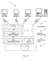
- the architecture of the system 1 is shown in Fig. 2 It has a three-tier architecture, which consists of a user interface layer 15 supporting the interfaces 7 and 13, a business services layer 16 supporting the functions 6 and 8, and a data services layer 17 supporting the database 9 and the integration engine 18.
- the functions are instantiated as objects from user interface, business logic, and data services classes. Objects are instantiated for a task such as a user enquiry session and are terminated at the end.
- This consists of a set of Web classes that reside on a Web server. Objects instantiated from these classes send HTML to a client browser.
- the primary role of the browser 7 is to view the data in a variety of ways i.e. graphically, tabular, by day, by month, by year.
- the browser front-end allows the measurement and management of performance. The measurement is by viewing the data in a variety of forms, and the management is by allowing the user to specify (according to his security privileges) targets, development plans, comments and even override results.
- the Web server interfaces with user Web clients 14.
- This consists of a set of forms which reside in the user interface layer 15. It sends the configuration data directly to the business services layer.
- the primary role of the interface 13 is to configure the browser 7 and to determine the behaviour of the data within the system 1.
- the Windows interface allows 'tailoring' of the system to meet the specific requirements and characteristics of the contact management centre, thus omitting the need for expensive customisation of the product.
- This layer comprises a business server on which resides the functions 6 and 8. These functions perform all calculations and all validations
- the interface 13 directly accesses the business server whilst the interface 7 accesses the business server via the Web server.
- the data services layer 17 comprises a data server hosting the database 9. This layers performs data integration with the external systems.
- a data server hosts data services objects in addition to the actual database 9.
- the business server calls the data services object, which then in turn reltieve data from the database 9.
- the system 1 also comprises a transaction server. This handles all of the database transactions between the objects in the business layer and the objects in the data services layer. It holds a pool of objects together, maintains a pool of database connections, and allows improved scalability and performance
- DLLs Dynamic Library Links
- proxy stub pairs When a function 6 requires the DLL, the proxy stub pairs direct the function to the DLL stored on the server. The proxy stub pairs therefore enable the objects to communicate with each other across multiple servers.
- the configuration functions 8 include a call centre configuration function, a hierarchy maintenance function, and a data dictionary maintenance function.
- the information management functions 6 handle aspects such as personal development, setting objectives for agents, and processing agent awards.
- the integration engine 18 together with the data dictionary function provide comprehensive data for the information management functions 6.
- the call centre configuration function is used via the WindowsTM interface to construct the conceptual organisational hierarchy.
- the organisation can configure up to ten hierarchical levels.
- Fig. 3(a) shows an example for an organisation that has seven levels from agent through to the global organisation view.
- the screen of Fig. 3(b) then allows the user to determine functional access (at the browser end) to the various performance management functions for each level as specified in the system hierarchy in Fig. 3(a). This is inputted in a simple Yes/No cellular structure. Because the defined organisational hierarchy forms a basis for the operation of many other functions, amendments to the same can only be made by a senior systems administrator with the appropriate access and user rights.
- the call centre configuration function is coded in Visual BasicTM and refers to the characteristics of the customer services centre.
- a hierarchy configuration is then set up for each site using the hierarchy maintenance function.
- the fields completed for site configuration are call centre name, call centre ID, year and week start values, system days, close off data, currency mask and a moratorium value.
- the data dictionary maintenance function allows users to manipulate the measurement data that has been imported from the third party performance measurement systems.
- the primary purpose is to formulate the performance management system objective fields from all the data fields imported from the external third party databases or performance measurement systems.
- a sample screen is shown in Fig. 4(a), in which the user is creating a new data dictionary field that forms the measurement of schedule adherence (the percentage of time an agent actually spends signed-on to their phone against the time they were scheduled to be there).
- schedule adherence the percentage of time an agent actually spends signed-on to their phone against the time they were scheduled to be there.
- the user inputs a name description, associates the data dictionary field to a level in the hierarchy, and specifies the period against which the measurement data is captured. The level must be chosen from the set established when creating the organisation hierarchy.
- a second screen shown in Fig.
- Field Name Mandatory / Optional Field Behaviour Field Description Field - Displayed This column displays the database fields that may be entered. Description - Displayed This column displays the description associated with the field. This cannot be edited by the user within the DDM 22 as it is display only. It is stored within the DDM. Value1 M Input This fields allows the user to enter the summation formula for the summary periods. A result will be produced for all periods regardless of whether the period was chosen as a rating period in the objective wizard function.
- Command Name Description TEST This allows the user to test the full formula entered. A result of the formula is displayed from skeleton test data in the database. OK Saves any changes / additions made by the user without prompting for confirmation of same; and quits component / application. CANCEL If change / additions made, prompts user to save same; otherwise quits component / application. HELP Opens Help file for component.
- Fig. 4(c) shows an input screen used to define the data dictionary rules. These rules define how the result for the field is entered, displayed, and calculated. As illustrated in Fig. 4(c) the minimum and maximum values are set, as is the display mask. In this case ##% means that the result will be displayed as a % and rounded up with no decimal places.
- the over-ride check box allows the organisation to control whether or not these results can be over-ridden by a user's manager.
- the following table describes the inputs in more detail.
- Field Name Mandatory / Optional Field Behaviour Field Description Min Value O Input. This field is used to restrict the input permitted for a manual data entry or a result override. The value entered must be greater than or equal to this value. Max Value O Input.
- This field is used to restrict the input permitted for a manual data entry or a result override. The value entered must be less than or equal to this value.
- Display Mask O Input Determines how the result for the data dictionary field will be displayed. Used to indicate currency, percentage, minutes or seconds.
- KPI O Check Indicates that this data dictionary field will be used in conjunction with key performance indicators
- Manual O Check Indicates that this data dictionary field will require a manager to enter a result manually and that data will not be populated automatically from the switch.
- Override O Check Indicates that results for this data dictionary field cannot be over-ridden in the team performance review screen. This field will be used where the formula for the data dictionary is deemed too complicated to allow values to be changed.
- Command Name Description OK Saves any changes / additions made by the user without prompting for confirmation of same; and quits component / application. CANCEL If change / additions made, prompts user to save same; otherwise quits component / application.
- HELP Opens Help file for component, if in WinHelp then the topic is generally (but not always) specific to the tab / component the user is currently using.
- a data dictionary is to be used to provide data for the key performance indicators (KPI's), then it must be entered above the highest level specified.
- the level for the AHT would have be the level higher than the highest level specified in Hierarchy Maintenance, i.e.: if the highest level in Hierarchy Maintenance was 'Organisation' at Level 7, then the Data Dictionary for AHT must be specified at Level 8.
- the display mask must be configured to reflect the maximum characters as specified in the 'Max Value' field., i.e. if the maximum value is 4 characters (1000) then the display mask must provide provision for 4 characters (###0) Reason
- the input mask must provide provision for all the characters entered into the data dictionary field Typical Scenario A manual entry data dictionary is set-up called 'revenue', which will have a maximum amount of £1,000,000. The call centre wish this to be displayed with commas separating every 3 characters, a '£' sign and to 2 decimal places, therefore the input mask is specified as '£#, ###, ##0.00
- the information management functions 6 require a comprehensive range of import data to adequately perform the required processing with use of the data dictionary configuration.
- the imports are performed by the integration engine 18.
- the integration engine allows flexibility in the nature of valid source data systems.
- the integration engine 18 comprises a configuration function. This generates an integration folder comprising external systems, mappings, and parameters sub-folders. These sub-folders effectively configure the integration engine 18.
- the configuration function generates a display as shown in Fig. 5 for selection of the external system ODBC data source and to input the username, password, and additional parameters. This registers the external system.
- the configuration function then defines the external system data to be extracted in the form of mappings.
- the mappings are between one or more data sources of the external system and a data container column in the system database 9. Any SQL arithmetic may be applied under user instructions by the configuration function.
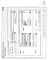
- the sample screen of Fig. 6 illustrates definition of a simple mapping in which data from two columns of the external system is added and the result imported into a data container column of the system 1.
- mappings may perform filtering according to set criteria, in an "advanced" panel, described below.
- the integration engine 18 translates each configured mapping into an ODBC SQL statement for extraction system. All mappings are processed together so that the integration engine 18 generates the most efficient SQL statements so that data is extracted with execution of as few SQL statements as possible. This ensures that the import to the system 1 has the minimum impact on performance of the relevant external system.
- the external systems are indicted generally by the numeral 50.
- a step 51 the SQL statements are executed to implement the defined mappings and transfer data to an ODBC container 52.
- the integration engine then in step 53 consolidates the imported data by employee and delivers the consolidated data to separate containers 54.
- the containers are in this embodiment SWTCHDATA, WFMDATA, and ACCSSDATA one for each external system.
- the data is consolidated so that for each container each agent has only one row of data attributed to him/her.
- the consolidated data is delivered to the containers 54 according to a data container column configurator defined in a data container table.
- step 55 the integration engine then merges selected data from these containers into an internal ForeignData Container table 56 consolidated into 1 row (made up of multiple fields) per employee.
- the merged data is then used for generating results in step 56 according to the data dictionary definitions 57.
- Field Name Mandatory / Optional Field Behaviour Field Description System O Display This field displays the name of the external system as configured by the user Data Source O Display If the system is configured by specifying the data source, then the data source is displayed in this field. If this field is populated then the connection string field cannot be populated Field Length: 255 characters Connection String O Display If the system is configured by specifying String the connection string, then the connection string is displayed in this field. If this field is populated then the data source field cannot be populated Field Length: 255 characters
- Command Name Description NEW Launches the External System Configuration sub screen with all fields blank EDIT Launches the External System Configuration sub screen with all fields pre-populated with the configured data DELETE Deletes the highlighted entry after prompting the user for confirmation
- this screen allows the user to specify a name for the external data source, and configure the external system by using either the data source or connection string.
- This screen is launched by activating the 'New' or 'Edit' command button from 'System' tab on the main screen.
- a call centre needs to interface a performance management system with their workforce management system. Therefore, the external systems configuration screen is launched from the main screen by activating the 'Add' command button.
- the user specifies the name of the external system as 'Workforce' and then decides how the external system should be configured by either entering the connection string or specifying the data source.
- the user selects a data source, and enters a username and password. To test that the username and password are correct the user activates the 'Connect' command button, which returns a dialogue box that the connection was successful.
- the values available for selection are all the data sources available form the 'User DSN' and 'System DSN' tab under ODBC data source administrator in Windows NT This field, once populated by a value, can never be blanked out.
- Field Length 255 characters Username M (if Data Source is selected) Input Free format alpha numeric text which allows the user to specify the username for the external system This field can never be blank
- Field Length 255 characters Password M (if Data Source is selected)
- Input Free format alpha numeric text which allows the user to specify the password for the external system
- This field can never be blank
- Field Length 255 characters Additional O (if Data Source is selected)
- Input Free format alpha numeric text which allows the user to specify any additional information required to connect to the database for the external system
- Field Length 255 characters Connection String O Mutually exclusive radio button Default: disabled This field, if true, indicates that the external system will be configured by specifying the connection string.
- Connection String Connection String M (if Connection String is selected) Input Free format alpha numeric text which allows the user to specify the connection string for the external system This field, once populated by a value, can never be blanked out.
- Field Length 255 characters
- Command Name Description OK Saves changes and exits the application CANCEL If changes have been made prompts the user to save, otherwise quits the application HELP Opens the Help file for the application
- this screen allows the user to map the external systems database columns with columns in the data containers. It also allows the call centre to associate a name with the column in the data container that would populate the DATAFIELDNAME table and hence be displayed to the user in the data dictionary maintenance.
- the screen also allows the user to specify formulae with the source data fields, so that the Acumen Data Containers can hold calculated data. This function allows this whilst ensuring that the minimum amount of SQL expressions are executed, hence optimising performance.
- a call centre needs to integrate a performance management system with their switch. Therefore, all the required fields within the switch need to be mapped onto the switch data containers.
- the implementation consultant would launch the screen of Fig. 6 and enter the name of the data field within the system 1 that the column in the switch would correspond to.
- the implementation consultant selects the data container and column within the data container that the specified external system column is to be mapped to, and the measurement period for the data.
- the implementation consultant then specifies the source system as 'Switch' and selects the column within the table that needs to be mapped to the data container. By double clicking a column in the 'Column' list box, that column appears below in the column expression text box.
- the Consultant may use the 'Column' list box to double click a number of columns - successive columns appear in the column expression text box separated by pluses. For example, double clicking 'CD_CALL_TIME' followed by 'CD_NUM_CALLS' would result in 'CD_CALL_TIME + CD_NUM_CALLS'.
- the Consultant may then edit this to be 'CD_CALL_TIME /CD_NOM_CALLS'.
- the implementation consultant specifies for each table a unique identifier (Agent ID) for each agent. Also, if available, a date column within each table must be specified.
- Field Name mandatory / Optional Field Behaviour Field Description Data Field Name M Input Free format alphanumeric text that allows the user to specify the data field name. This will then be used to identify the name of the foreign value and be displayed to the user in the data dictionary maintenance.
- Field Length 18 characters
- WFMDATACONTAINER 3. ACCSSDATACONATINER 4.
- KPIDATACONTAINER Once specified the field can never be blanked out Field Length: 20 characters Column M Selection Drop down combo Default: Blank The column within the data container that is to be mapped to. This is pre-populated once the 'Data Container' field is populated with a true value and lists all the VALLTE fields within the data container Once specified the field can never be blanked out Field Length: 20 characters Measurement Period M Selection Drop down combo Default: Blank Allows the user to select a measurement period for the data. The measurement period specified in the data dictionary that uses this field must be identical. All Measurement periods are available for selection.
- Field Length 20 characters System M Selection Drop down combo Default: Blank
- the systems available for selection are those configured in the 'External System Configuration' utility
- Field Length 20 characters Table M Display Displays all the tables available in the table specified in the 'System' field. If a different system is selected in the 'System' field, this is refreshed to show the tables in the newly highlighted system.
- Field Length 255 characters Column expression M Display Displays the column SQL expression used to derive the data to be inserted into the data container column. This may be a single column from the table or some SQL expression based on 0 or more columns from the table.
- Field Length 500 characters Agent ID M Selection Drop down combo Default: Blank This field allows the user to select the column within the table that uniquely identifies the agent. The drop-down in this field displays all the columns available in the table specified in the 'Table' field Once specified the field can never be blanked out
- Field Length 20 characters Date O Selection Drop down combo Default: Blank Allows the user to select the column within the table that uniquely identifies the date.
- the drop-down in this field displays all the columns available in the table specified in the 'Table' field
- the data selected from the table will be filtered to only select rows where this date matches the date(s) for the overnight. For example, if the mapping has a Daily measurement period, only rows where the date column matches the system date will be selected.
- This field can be blanked out at any time Field Length: 20 characters Date Conversion O Selection Drop down combo Default: Blank Where a Date column has been selected, this allows the consultant to select a date conversion stored procedure that needs to be applied in order to translate the system 1 date format (YYYYMMDD) to that format used within the external database.
- a switch represents date using a numeric column where the date is in YYYMMDD format.
- the year 1999 in YYY format is 099, 2000 is 100 and 2001 is 101.
- a 'Date Conv' option would be available from this combo and when selected will cause a custom stored procedure within the database 9 to be invoked during data extraction, to change the system 1 date to the external system format.
- Command Name Description TEST Executes the SQL expression to ensure that a single numerical value is returned. Displays a dialogue box informing the user of either success or failure of the test. OK Saves changes and exits the application CANCEL If changes have been made prompts the user to save, otherwise quits the application HELP Opens the Help file for the application
- the integration engine 18 provides for advanced mapping with complex filtering of source data.
- a data container mapping screen is used when the 'Column Expression' functionality of the 'General' tab is insufficient to map the required data.
- the consultant uses the Advanced tab to define the data to be retrieved.
- the consultant enters an SQL 'select' statement that returns one 'column' of data - although that may be derived from a number of columns from one or more tables on the system.
- the consultant may also filter data to be returned by use of an SQL 'where' clause in the 'select' expression.
- the consultant may include parameters in the SQL text. Parameters are used to substitute variable values into the SQL expression. The parameter values may be changed as often as required and are substituted into the SQL expression just before it is executed during the overnight processing. Parameters are described in more detail below.
- the call centre may want to measure agents based on a 'compliance' form of data, for example, that the agent has not had more than three short calls.
- the consultant creates a new data field named 'Short Call Compliance' and chooses the data container, its column and measurement period. The system and table are chosen and then the Agent Id and Date columns are selected.
- the consultant wants to return a '1' where the number of short calls are less than or equal to three.
- Command Name Description TEST Executes the SQL expression to ensure that a single numerical value is returned. Displays a dialogue box informing the user of either success or failure of the test. OK Saves changes and exits the application CANCEL If changes have been made prompts the user to save, otherwise quits the application HELP Opens the Help file for the application
- a secondary screen for parameters is shown. Parameters may be used in the SQL entered by a consultant on the Advanced tab of the Data Container Mapping screen.
- the screen allows the user to view all the parameters configured within the system.
- the screen primary function is to maintain these data fields by allowing users to add, edit or delete data fields.
- a call centre wants to combine agent data between two days where an agent is working a nightshift.
- the Advanced SQL option is used and the consultant wants to filter data where the STARTTIME column is greater than or equal to the nightshift start time.
- a parameter named ':ShiftStart' is created with a value of 2200.
- the ':Shin:Start' parameter name is used in the SQL expressions.
- the nightshift start time is changed to 2230 - the consultant only needs to change the parameter value.
- Type O Display The parameter value type - either numeric, string or date. Value O Display The current value for the parameter. This is what will be substituted for the parameter's name in the SQL statement.
- Command Name Description NEW Launches the Parameter sub screen with all fields blank EDIT Launches the Parameter sub screen with all fields pre-populated with the configured data.
- 'System' parameters such as ':EXTRACT_FROM_DATE' may not be edited.
- DELETE Deletes the highlighted entry after prompting the user for confirmation and checking that the parameter is not already in use in a mapping's advanced SQL.
- 'System' parameters such as ':EXTRACT_FROM_DATE' may not be deleted.
- a sub-screen for specifying parameter properties is illustrated.
- This screen enables the user to alter the Name, Description, Type and Value of existing Parameters and to enter these details for new Parameters. It is launched by activating the 'New' or 'Edit' buttons of the Parameter browser.
- a consultant requires a parameter to be used in a Data Container Mapping's Advanced SQL statement.
- the 'New' button is activated on the parameter browser to display this screen.
- the user enters the parameter name starting with a colon, provides a description of the purpose of the parameter, selects the Numeric type and enters a numeric initial value for the parameter.
- Field Name Mandatory / Optional Field Behaviour Field Description Name
- M Input Parameter name starting with a colon, at least two characters long, with other characters being alphanumeric or underscore.
- Field Length 20 characters Description O Input Free format alpha numeric text allowing the user describe the purpose of the parameter.
- Field Length 255 characters
- Type M Selection Drop down combo Default Blank Allows the user to define whether the parameter is used to represent numeric, date or free format text values. Once specified the field can never be blanked out
- Field Length 20 characters Value M Input The current value for the parameter.
- Field Length 200 characters
- Command Name Description OK Saves changes and exits the application CANCEL If changes have been made prompts the user to save, otherwise quits the application HELP Opens the Help file for the application
- the integration engine 18 allows automatic and comprehensive transfer of data so that the systems are comprehensively integrated. This is important for optimum operation of the host system so that the fields are fully populated both with raw data and filtered or processed data.
- the integration engine 18 operates particularly well with the data dictionary of the host system.
Abstract
Description
- The invention relates to integration of data processing system to allow effective and automatic data transfer. An example is a performance management system capturing data from a switch, a work force manager, and other external systems.
- Various mechanisms are known for transfer of data, such as flat (ASCII) file transfer and use of APIs. However, they do not provide for very comprehensive transfer of data in a versatile and automated manner to the extent that the systems are effectively integrated.
- An object of the invention is to provide an integration engine which performs data transfer in a manner which is sufficiently comprehensive and "intelligent" to effectively integrate at least two data processing systems.
- According to the invention there is provided an integration engine for transfer of source data from a data processing external system to a data processing host system, the integration engine comprising:-
- a configuration function comprising means for defining the external system data to be exported, mappings to be applied to the exported data, and target locations in the host system for imported data, and
- an execution function comprising means for translating the mappings into executable program code, and for executing the code to import data into the host system.
-
- In one embodiment, the configuration function comprises means for generating an external system dataset, mappings dataset, and a parameter value dataset.
- In one embodiment, the configuration function comprises means for definition of target locations in the host system as data container columns.
- In one embodiment, the configuration function comprises means for defining mathematical function mappings in which source data from a plurality of locations in the external system is processed.
- In one embodiment, the execution function comprises means for consolidating the imported data according to persons for whom there are records in the host system.
- In one embodiment, the execution function comprises means for writing the consolidated data to a plurality of data containers of which there is at least one per external system.
- In one embodiment, data associated with each person is written to a single dataset in each container.
- In one embodiment, the execution function comprises means for merging selected data from said containers into a single foreign data container comprising a single dataset per person.
- In one embodiment, the execution function comprises means for generating interfacing with an information management function of the host system to generate output results.
- In one embodiment, the configuration function comprises means for defining filtering of the source data.
- In one embodiment, the configuration function comprises means for storing mapping operator statement for mapping of data from an external system to a data container.
- In one embodiment, the configuration function comprises means for associating the
statements 11 with parameter fields, having variable values. - In one embodiment, the host system is a performance management system and the external system is a customer services system.
- According to another aspect, the invention provides a host system comprising:-
- an integration engine as claimed in any preceding claim,
- information management functions for processing the imported data.
-
- In one embodiment, the host system is a performance management system further comprising:-
- a call centre configuration function for configuring call centre parameters in a configuration dataset, and
- a data dictionary function for formulating under user instructions, calculation rules, value inputs for rules, and storage parameters for database fields.
-
- In one embodiment, the user interface, the configuration functions, and the performance management functions together have a structure of classes for instantiating objects in a user interface layer, a business logic layer, and a data services layer.
- In one embodiment, the business logic class instantiates business logic objects having code of a configuration or an information function, and means for terminating the object at the end of a user session.
- In one embodiment, the business logic layer executes on a business server.
- In one embodiment, the data services layer comprises a class for instantiating data services objects residing on a database server and means for terminating said objects after a user session.
- In one embodiment, the system comprises a transaction server for executing data services layer functions.
- In one embodiment, the transaction server comprises means for maintaining a pool of data services objects together and for maintaining a pool of database connections.
- In one embodiment, dynamic library links for the objects are registered using proxy stub pairs on both a client and a server.
- In one embodiment, the integration engine comprises means for writing imported data to a foreign data table after execution of mappings and selection of particular fields, and in which the data is consolidated into one dataset per agent, and the information management functions comprises means for generating performance management results according to data definitions generated by the data dictionary function.
- The invention will be more clearly understood from the following description of some embodiments thereof, given by way of example only with reference to the accompanying drawings in which:-
- Fig. 1 is an overview block diagram of a performance management system;
- Fig. 2 is a diagram illustrating the physical architecture of the performance management system;
- Figs. 3 and 4 are sample screen shots illustrating operation of a data dictionary maintenance function;
- Figs. 5 and 6 are sample screen shots illustrating operation of an integration engine;
- Fig. 7 is a flow diagram illustrating data transfer paths; and
- Figs. 8 to 10 are sample screens illustrating operation of the integration engine.
-
- Referring to Fig. 1 there is shown a
performance management system 1 for the management of performance in a customer services environment and reporting on same. Thesystem 1 interfaces with externalperformance measurement systems 2 comprising aswitch 3, awork force manager 4, andthird party systems 5 that store performance measurement data within a structured database and can produce reports on either employee, application, departmental or organisational performance. - The
system 1 comprisesinformation management functions 6 which use data from a KPI (key performance indicator) table 10 and a results & ratings table 11 within adatabase 9 to perform calculations pertaining to individual performance of employees, in addition to the overall performance within the customer services centre. Theinformation management functions 6 interact with an HTMLuser interface 7 to display to the end-user the results of the calculations performed on performance. Thedatabase 9 also contains configuration data tables 12. The contents of these tables allow thesystem 1 to be tailored to suit individual organisations, thus minimising the need for bespoke development of the system to suit particular business operations. The configuration data is captured through use ofconfiguration functions 8, and a Windows™-basedinterface 13, which provides the user with a GUI to specify the unique characteristics of the organisation. - At a high level, the
database 9 captures raw data from theexternal systems 2 in a comprehensive and automated manner using anintegration engine 18. The performance data is provided in real time via the HTMLuser interface 7 in response to appropriate requests/enquiries. The performance data may relate to individual customer service agents, to teams, or to overall departments and even site locations. Performance is measured against objectives set up during configuration, and also against KPIs. Like objectives, KPIs have targets but are not rated. However they do not relate to persons, but instead to an organisation or department as a whole. - The architecture of the
system 1 is shown in Fig. 2 It has a three-tier architecture, which consists of auser interface layer 15 supporting theinterfaces business services layer 16 supporting thefunctions data services layer 17 supporting thedatabase 9 and theintegration engine 18. The functions are instantiated as objects from user interface, business logic, and data services classes. Objects are instantiated for a task such as a user enquiry session and are terminated at the end. - There are two types of user interface as follows.
- This consists of a set of Web classes that reside on a Web server. Objects instantiated from these classes send HTML to a client browser. The primary role of the
browser 7 is to view the data in a variety of ways i.e. graphically, tabular, by day, by month, by year. The browser front-end allows the measurement and management of performance. The measurement is by viewing the data in a variety of forms, and the management is by allowing the user to specify (according to his security privileges) targets, development plans, comments and even override results. The Web server interfaces withuser Web clients 14. - This consists of a set of forms which reside in the
user interface layer 15. It sends the configuration data directly to the business services layer. The primary role of theinterface 13 is to configure thebrowser 7 and to determine the behaviour of the data within thesystem 1. The Windows interface allows 'tailoring' of the system to meet the specific requirements and characteristics of the contact management centre, thus omitting the need for expensive customisation of the product. - This layer comprises a business server on which resides the
functions interface 13 directly accesses the business server whilst theinterface 7 accesses the business server via the Web server. - The data services
layer 17 comprises a data server hosting thedatabase 9. This layers performs data integration with the external systems. - A data server hosts data services objects in addition to the
actual database 9. The business server calls the data services object, which then in turn reltieve data from thedatabase 9. - The
system 1 also comprises a transaction server. This handles all of the database transactions between the objects in the business layer and the objects in the data services layer. It holds a pool of objects together, maintains a pool of database connections, and allows improved scalability and performance - Dynamic Library Links (DLLs) are registered using proxy stub pairs on both the servers and on the clients. When a
function 6 requires the DLL, the proxy stub pairs direct the function to the DLL stored on the server. The proxy stub pairs therefore enable the objects to communicate with each other across multiple servers. - The configuration functions 8 include a call centre configuration function, a hierarchy maintenance function, and a data dictionary maintenance function.
- The information management functions 6 handle aspects such as personal development, setting objectives for agents, and processing agent awards.
- The
integration engine 18 together with the data dictionary function provide comprehensive data for the information management functions 6. - The call centre configuration function is used via the Windows™ interface to construct the conceptual organisational hierarchy. The organisation can configure up to ten hierarchical levels. Fig. 3(a) shows an example for an organisation that has seven levels from agent through to the global organisation view. The screen of Fig. 3(b) then allows the user to determine functional access (at the browser end) to the various performance management functions for each level as specified in the system hierarchy in Fig. 3(a). This is inputted in a simple Yes/No cellular structure. Because the defined organisational hierarchy forms a basis for the operation of many other functions, amendments to the same can only be made by a senior systems administrator with the appropriate access and user rights.
- The call centre configuration function is coded in Visual Basic™ and refers to the characteristics of the customer services centre.
- After the call centre configuration has been defined a hierarchy configuration is then set up for each site using the hierarchy maintenance function. The fields completed for site configuration are call centre name, call centre ID, year and week start values, system days, close off data, currency mask and a moratorium value.
- The data dictionary maintenance function allows users to manipulate the measurement data that has been imported from the third party performance measurement systems. The primary purpose is to formulate the performance management system objective fields from all the data fields imported from the external third party databases or performance measurement systems. A sample screen is shown in Fig. 4(a), in which the user is creating a new data dictionary field that forms the measurement of schedule adherence (the percentage of time an agent actually spends signed-on to their phone against the time they were scheduled to be there). As illustrated, the user inputs a name description, associates the data dictionary field to a level in the hierarchy, and specifies the period against which the measurement data is captured. The level must be chosen from the set established when creating the organisation hierarchy. A second screen, shown in Fig. 4(b), is used to assign the data dictionary name to a database field or a combination of database fields and defining how these fields are to be calculated. The calculation is defined by a
Value 1/Operator/Value 2 sequence. In the example Fig. 4(b), the user selects the field [fgn_value5] which relates to the actual time the agent was signed-in (taken from the ACD) and divides this by [fgn_value21] which relates to the amount of time they had been scheduled to be signed-in (taken from the Workforce Management System). - The following table sets out the field descriptions in more detail.
Field Name Mandatory / Optional Field Behaviour Field Description Field - Displayed This column displays the database fields that may be entered. Description - Displayed This column displays the description associated with the field. This cannot be edited by the user within the DDM 22 as it is display only. It is stored within the DDM. Value1 M Input This fields allows the user to enter the summation formula for the summary periods.
A result will be produced for all periods regardless of whether the period was chosen as a rating period in the objective wizard function.
Supported
All approved ANSI 92 SQL Statements
The result of this part of the formula will be stored in the database and used to sum results for period and teamsOperator O
Mandatory if Value2 is enteredSelection This operator makes up the complete formula using Value1 and Value2. Initially the data from the foreign data table is calculated using the full formula. To calculate the sum for periods and teams, the formula Value1 Operator Value2 will be used.
Available operators
+ ; - ; /; *Value2 O Input This fields allows the user enter the second part of the summation formula. This field may not be required for similar formulae of a field assignment.
Supported
All approved ANSI 92 SQL Statements
The result of this part of the formula will be stored in the database and used to sum results for period and teamsResult - Display Displays the result of an expression based on skeleton data, when the 'TEST' option is selected. - The following table sets out the command options.
Command Name Description TEST This allows the user to test the full formula entered. A result of the formula is displayed from skeleton test data in the database. OK Saves any changes / additions made by the user without prompting for confirmation of same; and quits component / application. CANCEL If change / additions made, prompts user to save same; otherwise quits component / application. HELP Opens Help file for component. - Fig. 4(c) shows an input screen used to define the data dictionary rules. These rules define how the result for the field is entered, displayed, and calculated. As illustrated in Fig. 4(c) the minimum and maximum values are set, as is the display mask. In this case ##% means that the result will be displayed as a % and rounded up with no decimal places. The over-ride check box allows the organisation to control whether or not these results can be over-ridden by a user's manager. The following table describes the inputs in more detail.
Field Name Mandatory / Optional Field Behaviour Field Description Min Value O Input. This field is used to restrict the input permitted for a manual data entry or a result override. The value entered must be greater than or equal to this value. Max Value O Input. This field is used to restrict the input permitted for a manual data entry or a result override. The value entered must be less than or equal to this value. Display Mask O Input Determines how the result for the data dictionary field will be displayed. Used to indicate currency, percentage, minutes or seconds. KPI O Check Indicates that this data dictionary field will be used in conjunction with key performance indicators KPI's and not objectives Manual O Check Indicates that this data dictionary field will require a manager to enter a result manually and that data will not be populated automatically from the switch. Override O Check Indicates that results for this data dictionary field cannot be over-ridden in the team performance review screen. This field will be used where the formula for the data dictionary is deemed too complicated to allow values to be changed. - The following are the command options
Command Name Description OK Saves any changes / additions made by the user without prompting for confirmation of same; and quits component / application. CANCEL If change / additions made, prompts user to save same; otherwise quits component / application. HELP Opens Help file for component, if in WinHelp then the topic is generally (but not always) specific to the tab / component the user is currently using. - The following are the business rules.
Description If the data dictionary created is to be used to provide data for the key performance indicators (KPI's), then it must be entered above the highest level specified. Reason Entering the data dictionary that is to be used in conjunction with a KPI at the highest level Typical A data dictionary is to be created for Average Handling Time Scenario (AHT), this will also be later used as a Key Performance Indicator. The level for the AHT would have be the level higher than the highest level specified in Hierarchy Maintenance, i.e.: if the highest level in Hierarchy Maintenance was 'Organisation' at Level 7, then the Data Dictionary for AHT must be specified atLevel 8. - The following are the best practices.
Description The display mask must be configured to reflect the maximum characters as specified in the 'Max Value' field., i.e. if the maximum value is 4 characters (1000) then the display mask must provide provision for 4 characters (###0) Reason The input mask must provide provision for all the characters entered into the data dictionary field Typical Scenario A manual entry data dictionary is set-up called 'revenue', which will have a maximum amount of £1,000,000. The call centre wish this to be displayed with commas separating every 3 characters, a '£' sign and to 2 decimal places, therefore the input mask is specified as '£#, ###, ##0.00 - It will be appreciated that the information management functions 6 require a comprehensive range of import data to adequately perform the required processing with use of the data dictionary configuration. As stated above the imports are performed by the
integration engine 18. The integration engine allows flexibility in the nature of valid source data systems. - The
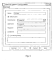
integration engine 18 comprises a configuration function. This generates an integration folder comprising external systems, mappings, and parameters sub-folders. These sub-folders effectively configure theintegration engine 18. - The configuration function generates a display as shown in Fig. 5 for selection of the external system ODBC data source and to input the username, password, and additional parameters. This registers the external system.
- The configuration function then defines the external system data to be extracted in the form of mappings. The mappings are between one or more data sources of the external system and a data container column in the
system database 9. Any SQL arithmetic may be applied under user instructions by the configuration function. The sample screen of Fig. 6 illustrates definition of a simple mapping in which data from two columns of the external system is added and the result imported into a data container column of thesystem 1. - The mappings may perform filtering according to set criteria, in an "advanced" panel, described below.
- The
integration engine 18 translates each configured mapping into an ODBC SQL statement for extraction system. All mappings are processed together so that theintegration engine 18 generates the most efficient SQL statements so that data is extracted with execution of as few SQL statements as possible. This ensures that the import to thesystem 1 has the minimum impact on performance of the relevant external system. - Referring now to Fig. 7, the external systems are indicted generally by the numeral 50. In a
step 51 the SQL statements are executed to implement the defined mappings and transfer data to anODBC container 52. The integration engine then instep 53 consolidates the imported data by employee and delivers the consolidated data to separatecontainers 54. The containers are in this embodiment SWTCHDATA, WFMDATA, and ACCSSDATA one for each external system. The data is consolidated so that for each container each agent has only one row of data attributed to him/her. The consolidated data is delivered to thecontainers 54 according to a data container column configurator defined in a data container table. - In
step 55, the integration engine then merges selected data from these containers into an internal ForeignData Container table 56 consolidated into 1 row (made up of multiple fields) per employee. The merged data is then used for generating results instep 56 according to thedata dictionary definitions 57. - In more detail, the following are the field descriptions for the initial stage of configuring the integration engine for integration of a new performance management system with a switch.
Field Name Mandatory / Optional Field Behaviour Field Description System O Display This field displays the name of the external system as configured by the user Data Source O Display If the system is configured by specifying the data source, then the data source is displayed in this field. If this field is populated then the connection string field cannot be populated
Field Length: 255 charactersConnection String O Display If the system is configured by specifying String the connection string, then the connection string is displayed in this field. If this field is populated then the data source field cannot be populated
Field Length: 255 characters - The following are the command options.
Command Name Description NEW Launches the External System Configuration sub screen with all fields blank EDIT Launches the External System Configuration sub screen with all fields pre-populated with the configured data DELETE Deletes the highlighted entry after prompting the user for confirmation - Referring again to Fig. 5, this screen allows the user to specify a name for the external data source, and configure the external system by using either the data source or connection string. This screen is launched by activating the 'New' or 'Edit' command button from 'System' tab on the main screen.
- In a typical scenario, a call centre needs to interface a performance management system with their workforce management system. Therefore, the external systems configuration screen is launched from the main screen by activating the 'Add' command button. The user specifies the name of the external system as 'Workforce' and then decides how the external system should be configured by either entering the connection string or specifying the data source. The user selects a data source, and enters a username and password. To test that the username and password are correct the user activates the 'Connect' command button, which returns a dialogue box that the connection was successful.
- The following are the field descriptions.
Field Name Mandatory / Optional Field Behaviour Field Description Name M Input Free format alpha numeric text which allows the user to specify a name for the external system
Field length: 20 charactersData Source O Mutually exclusive radio button Default: enabled This field, if true, indicates that the external system will be configured by specifying the data source.
If this field is enabled/disabled the following fields are enabled/disabled:
1. Data Source
2. User Name
3. Password
4. AdditionalData Source M (if Data Source is selected) Selection Drop down combo Default: Blank This field allows the user to specify the data source.
The values available for selection are all the data sources available form the 'User DSN' and 'System DSN' tab under ODBC data source administrator in Windows NT
This field, once populated by a value, can never be blanked out.
Field Length: 255 charactersUsername M (if Data Source is selected) Input Free format alpha numeric text which allows the user to specify the username for the external system
This field can never be blank
Field Length: 255 charactersPassword M (if Data Source is selected) Input Free format alpha numeric text which allows the user to specify the password for the external system
This field can never be blank
Field Length: 255 charactersAdditional O (if Data Source is selected) Input Free format alpha numeric text which allows the user to specify any additional information required to connect to the database for the external system
Field Length: 255 charactersConnection String O Mutually exclusive radio button Default: disabled This field, if true, indicates that the external system will be configured by specifying the connection string.
If this field is enabled/disabled the following fields are enabled/disabled:
1. Connection StringConnection String M (if Connection String is selected) Input Free format alpha numeric text which allows the user to specify the connection string for the external system
This field, once populated by a value, can never be blanked out.
Field Length: 255 characters - The following are the command options.
Command Name Description OK Saves changes and exits the application CANCEL If changes have been made prompts the user to save, otherwise quits the application HELP Opens the Help file for the application - Referring again to Fig. 6, this screen allows the user to map the external systems database columns with columns in the data containers. It also allows the call centre to associate a name with the column in the data container that would populate the DATAFIELDNAME table and hence be displayed to the user in the data dictionary maintenance. The screen also allows the user to specify formulae with the source data fields, so that the Acumen Data Containers can hold calculated data. This function allows this whilst ensuring that the minimum amount of SQL expressions are executed, hence optimising performance.
- In a typical scenario, a call centre needs to integrate a performance management system with their switch. Therefore, all the required fields within the switch need to be mapped onto the switch data containers. The implementation consultant would launch the screen of Fig. 6 and enter the name of the data field within the
system 1 that the column in the switch would correspond to. - The implementation consultant then selects the data container and column within the data container that the specified external system column is to be mapped to, and the measurement period for the data.
- The implementation consultant then specifies the source system as 'Switch' and selects the column within the table that needs to be mapped to the data container. By double clicking a column in the 'Column' list box, that column appears below in the column expression text box. The Consultant may use the 'Column' list box to double click a number of columns - successive columns appear in the column expression text box separated by pluses. For example, double clicking 'CD_CALL_TIME' followed by 'CD_NUM_CALLS' would result in 'CD_CALL_TIME + CD_NUM_CALLS'. The Consultant may then edit this to be 'CD_CALL_TIME /CD_NOM_CALLS'.
- The implementation consultant specifies for each table a unique identifier (Agent ID) for each agent. Also, if available, a date column within each table must be specified.
Field Name Mandatory / Optional Field Behaviour Field Description Data Field Name M Input Free format alphanumeric text that allows the user to specify the data field name. This will then be used to identify the name of the foreign value and be displayed to the user in the data dictionary maintenance. Field Length: 18 characters Data Container M Selection Drop down combo Default: Blank The data container that will be mapped to, the possible values that could populate this field are: 1. SWTCHDATACONTAINER 2. WFMDATACONTAINER 3. ACCSSDATACONATINER 4. KPIDATACONTAINER Once specified the field can never be blanked out Field Length: 20 characters Column M Selection Drop down combo Default: Blank The column within the data container that is to be mapped to. This is pre-populated once the 'Data Container' field is populated with a true value and lists all the VALLTE fields within the data container Once specified the field can never be blanked out Field Length: 20 characters Measurement Period M Selection Drop down combo Default: Blank Allows the user to select a measurement period for the data. The measurement period specified in the data dictionary that uses this field must be identical. All Measurement periods are available for selection. Once specified the field can never be blanked out Field Length: 20 characters System M Selection Drop down combo Default: Blank The external system that is to be specified as the source for Acumen. The systems available for selection are those configured in the 'External System Configuration' utility Once specified the field can never be blanked out Field Length: 20 characters Table M Display Displays all the tables available in the table specified in the 'System' field. If a different system is selected in the 'System' field, this is refreshed to show the tables in the newly highlighted system. Field Length: 255 characters Column chooser O Display Displays all the columns available in the table specified in the 'Table' field. If a different table is highlighted in the 'Table' field then this field is refreshed to show the columns in the newly highlighted table. Field Length: 255 characters Column expression M Display Displays the column SQL expression used to derive the data to be inserted into the data container column. This may be a single column from the table or some SQL expression based on 0 or more columns from the table. Field Length: 500 characters Agent ID M Selection Drop down combo Default: Blank This field allows the user to select the column within the table that uniquely identifies the agent. The drop-down in this field displays all the columns available in the table specified in the 'Table' field Once specified the field can never be blanked out Field Length: 20 characters Date O Selection Drop down combo Default: Blank Allows the user to select the column within the table that uniquely identifies the date. The drop-down in this field displays all the columns available in the table specified in the 'Table' field By selecting a column from this combo, the data selected from the table will be filtered to only select rows where this date matches the date(s) for the overnight. For example, if the mapping has a Daily measurement period, only rows where the date column matches the system date will be selected. This field can be blanked out at any time Field Length: 20 characters Date Conversion O Selection Drop down combo Default: Blank Where a Date column has been selected, this allows the consultant to select a date conversion stored procedure that needs to be applied in order to translate the system 1 date format (YYYYMMDD) to that format used within the external database.For example, a switch represents date using a numeric column where the date is in YYYMMDD format. The year 1999 in YYY format is 099, 2000 is 100 and 2001 is 101. In this case, a 'Date Conv' option would be available from this combo and when selected will cause a custom stored procedure within the database 9 to be invoked during data extraction, to change thesystem 1 date to the external system format. - The following are the command options.
Command Name Description TEST Executes the SQL expression to ensure that a single numerical value is returned. Displays a dialogue box informing the user of either success or failure of the test. OK Saves changes and exits the application CANCEL If changes have been made prompts the user to save, otherwise quits the application HELP Opens the Help file for the application - As stated above, the
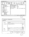
integration engine 18 provides for advanced mapping with complex filtering of source data. Referring to Fig. 8 a data container mapping screen is used when the 'Column Expression' functionality of the 'General' tab is insufficient to map the required data. Having configured all fields of the mapping on the general tab rather than using the Column Chooser Combo and Column Expression Text Box, the consultant uses the Advanced tab to define the data to be retrieved.
The consultant enters an SQL 'select' statement that returns one 'column' of data - although that may be derived from a number of columns from one or more tables on the system. The consultant may also filter data to be returned by use of an SQL 'where' clause in the 'select' expression. In addition to entering valid SQL, the consultant may include parameters in the SQL text. Parameters are used to substitute variable values into the SQL expression. The parameter values may be changed as often as required and are substituted into the SQL expression just before it is executed during the overnight processing. Parameters are described in more detail below. - In a typical scenario, the call centre may want to measure agents based on a 'compliance' form of data, for example, that the agent has not had more than three short calls. The consultant creates a new data field named 'Short Call Compliance' and chooses the data container, its column and measurement period. The system and table are chosen and then the Agent Id and Date columns are selected.
- The consultant wants to return a '1' where the number of short calls are less than or equal to three. The 'Advanced' tab is chosen and the consultant enters 'select 1 from DAGENT where SHORT_CALLS <= 3'.
- Alternatively, the consultant may use a parameter instead of the constant '3' - e.g. 'select 1 from DAGENT where SHORT_CALLS <= :MAX_SHT_CALLS'
- The following describes the fields.
Field Name Mandatory / Optional Field Behaviour Field Description Override All With M Check box Default: false Allows the consultant to select whether the 'Column Expression' text box on the 'General' tab is overridden by the contents of the SQL edit text on this Advanced tab. SQL edit text O Display / Input If the 'Override All With' check box is checked, this displays the SQL expression used to extract the data for the data container column. - The following are the command options.
Command Name Description TEST Executes the SQL expression to ensure that a single numerical value is returned. Displays a dialogue box informing the user of either success or failure of the test. OK Saves changes and exits the application CANCEL If changes have been made prompts the user to save, otherwise quits the application HELP Opens the Help file for the application - Referring to Fig. 9 a secondary screen for parameters is shown. Parameters may be used in the SQL entered by a consultant on the Advanced tab of the Data Container Mapping screen. The screen allows the user to view all the parameters configured within the system. The screen primary function is to maintain these data fields by allowing users to add, edit or delete data fields.
- There are several 'System' parameters such as ':EXTRACT_FROM_DATE' and ':EXTRACT_TO_DATE' that may not be edited or deleted from the system.
- In a typical scenario, a call centre wants to combine agent data between two days where an agent is working a nightshift. In this case, the Advanced SQL option is used and the consultant wants to filter data where the STARTTIME column is greater than or equal to the nightshift start time. Rather than including the current nightshift start time (2200) into the SQL expressions, a parameter named ':ShiftStart' is created with a value of 2200. The ':Shin:Start' parameter name is used in the SQL expressions. Later, the nightshift start time is changed to 2230 - the consultant only needs to change the parameter value.
- The following are the field descriptions.
Field Name Mandatory / Optional Field Behaviour Field Description Name O Display The parameter name - this must start with a colon, be two or more characters long up to a maximum of twenty characters and other than the colon, contain only alphanumeric or underscore characters. Type O Display The parameter value type - either numeric, string or date. Value O Display The current value for the parameter. This is what will be substituted for the parameter's name in the SQL statement. Description O Display A description of the purpose of the parameter. - The following are the command options.
Command Name Description NEW Launches the Parameter sub screen with all fields blank EDIT Launches the Parameter sub screen with all fields pre-populated with the configured data. 'System' parameters such as ':EXTRACT_FROM_DATE' may not be edited. DELETE Deletes the highlighted entry after prompting the user for confirmation and checking that the parameter is not already in use in a mapping's advanced SQL. 'System' parameters such as ':EXTRACT_FROM_DATE' may not be deleted. - Referring to Fig. 10 a sub-screen for specifying parameter properties is illustrated. This screen enables the user to alter the Name, Description, Type and Value of existing Parameters and to enter these details for new Parameters. It is launched by activating the 'New' or 'Edit' buttons of the Parameter browser.
- As an example, a consultant requires a parameter to be used in a Data Container Mapping's Advanced SQL statement. The 'New' button is activated on the parameter browser to display this screen. The user enters the parameter name starting with a colon, provides a description of the purpose of the parameter, selects the Numeric type and enters a numeric initial value for the parameter.
- The following are the field descriptions.
Field Name Mandatory / Optional Field Behaviour Field Description Name M Input Parameter name starting with a colon, at least two characters long, with other characters being alphanumeric or underscore.
Field Length: 20 charactersDescription O Input Free format alpha numeric text allowing the user describe the purpose of the parameter.
Field Length: 255 charactersType M Selection Drop down combo Default: Blank Allows the user to define whether the parameter is used to represent numeric, date or free format text values.
Once specified the field can never be blanked out
Field Length: 20 charactersValue M Input The current value for the parameter.
Field Length: 200 characters - The following are the command options.
Command Name Description OK Saves changes and exits the application CANCEL If changes have been made prompts the user to save, otherwise quits the application HELP Opens the Help file for the application - It will be appreciated that the invention provides for comprehensive integration of a system such as a performance management system with an external system. The
integration engine 18 allows automatic and comprehensive transfer of data so that the systems are comprehensively integrated. This is important for optimum operation of the host system so that the fields are fully populated both with raw data and filtered or processed data. Theintegration engine 18 operates particularly well with the data dictionary of the host system. - The invention is not limited to the embodiments described but may be varied in construction and detail.
Claims (10)
- An integration engine for transfer of source data from a data processing external system to a data processing host system, the integration engine comprising: -a configuration function comprising means for defining the external system data to be exported, mappings to be applied to the exported data, and target locations in the host system for imported data, andan execution function comprising means for translating the mappings into executable program code, and for executing the code to import data into the host system.
- An integration engine as claimed in claim 1, wherein the configuration function comprises means for generating an external system dataset, mappings dataset, and a parameter value dataset.
- An integration engine as claimed in claims 1 or 2, wherein the configuration function comprises means for definition of target locations in the host system as data container columns.
- An integration engine as claimed in claim 1, wherein the configuration function comprises means for defining mathematical function mappings in which source data from a plurality of locations in the external system is processed.
- An integration engine as claimed in claim 1, wherein the execution function comprises means for consolidating the imported data according to persons for whom there are records in the host system.
- An integration engine as claimed in claim 5, wherein the execution function comprises means for writing the consolidated data to a plurality of data containers of which there is at least one per external system.
- An integration engine as claimed in claim 1, wherein the configuration function comprises means for defining filtering of the source data.
- An integration engine as claimed in claim 1, wherein the host system is a performance management system and the external system is a customer services system.
- A host system comprising:-an integration engine as claimed in any preceding claim,information management functions for processing the imported data.
- A host system as claimed in claim 9, wherein the host system is a performance management system further comprising:-a call centre configuration function for configuring call centre parameters in a configuration dataset, anda data dictionary function for formulating under user instructions, calculation rules, value inputs for rules, and storage parameters for database fields.
Applications Claiming Priority (2)
| Application Number | Priority Date | Filing Date | Title |
|---|---|---|---|
| PCT/IE2000/000112 WO2002029631A1 (en) | 2000-09-29 | 2000-09-29 | Integration of data processing systems |
| EP00962779A EP1320810B1 (en) | 2000-09-29 | 2000-09-29 | Integration of data processing systems |
Related Parent Applications (1)
| Application Number | Title | Priority Date | Filing Date |
|---|---|---|---|
| EP00962779A Division EP1320810B1 (en) | 2000-09-29 | 2000-09-29 | Integration of data processing systems |
Publications (1)
| Publication Number | Publication Date |
|---|---|
| EP1605372A1 true EP1605372A1 (en) | 2005-12-14 |
Family
ID=11042191
Family Applications (2)
| Application Number | Title | Priority Date | Filing Date |
|---|---|---|---|
| EP05075788A Ceased EP1605372A1 (en) | 2000-09-29 | 2000-09-29 | Integration of data processing systems |
| EP00962779A Expired - Lifetime EP1320810B1 (en) | 2000-09-29 | 2000-09-29 | Integration of data processing systems |
Family Applications After (1)
| Application Number | Title | Priority Date | Filing Date |
|---|---|---|---|
| EP00962779A Expired - Lifetime EP1320810B1 (en) | 2000-09-29 | 2000-09-29 | Integration of data processing systems |
Country Status (5)
| Country | Link |
|---|---|
| EP (2) | EP1605372A1 (en) |
| AT (1) | ATE292823T1 (en) |
| AU (1) | AU2000274418A1 (en) |
| DE (1) | DE60019348D1 (en) |
| WO (1) | WO2002029631A1 (en) |
Families Citing this family (1)
| Publication number | Priority date | Publication date | Assignee | Title |
|---|---|---|---|---|
| CN106155718B (en) * | 2015-04-02 | 2019-09-06 | 阿里巴巴集团控股有限公司 | Flow engine implementation method and flow engine system |
Citations (3)
| Publication number | Priority date | Publication date | Assignee | Title |
|---|---|---|---|---|
| US5560005A (en) * | 1994-02-25 | 1996-09-24 | Actamed Corp. | Methods and systems for object-based relational distributed databases |
| US5806066A (en) * | 1996-03-26 | 1998-09-08 | Bull Hn Information Systems Inc. | Method of integrating schemas of distributed heterogeneous databases |
| WO2000013112A1 (en) * | 1998-08-31 | 2000-03-09 | Cabletron Systems, Inc. | Method and apparatus for managing data for use by data applications |
-
2000
- 2000-09-29 WO PCT/IE2000/000112 patent/WO2002029631A1/en active IP Right Grant
- 2000-09-29 AT AT00962779T patent/ATE292823T1/en not_active IP Right Cessation
- 2000-09-29 AU AU2000274418A patent/AU2000274418A1/en not_active Abandoned
- 2000-09-29 EP EP05075788A patent/EP1605372A1/en not_active Ceased
- 2000-09-29 EP EP00962779A patent/EP1320810B1/en not_active Expired - Lifetime
- 2000-09-29 DE DE60019348T patent/DE60019348D1/en not_active Expired - Lifetime
Patent Citations (3)
| Publication number | Priority date | Publication date | Assignee | Title |
|---|---|---|---|---|
| US5560005A (en) * | 1994-02-25 | 1996-09-24 | Actamed Corp. | Methods and systems for object-based relational distributed databases |
| US5806066A (en) * | 1996-03-26 | 1998-09-08 | Bull Hn Information Systems Inc. | Method of integrating schemas of distributed heterogeneous databases |
| WO2000013112A1 (en) * | 1998-08-31 | 2000-03-09 | Cabletron Systems, Inc. | Method and apparatus for managing data for use by data applications |
Also Published As
| Publication number | Publication date |
|---|---|
| ATE292823T1 (en) | 2005-04-15 |
| EP1320810B1 (en) | 2005-04-06 |
| WO2002029631A1 (en) | 2002-04-11 |
| DE60019348D1 (en) | 2005-05-12 |
| EP1320810A1 (en) | 2003-06-25 |
| AU2000274418A1 (en) | 2002-04-15 |
Similar Documents
| Publication | Publication Date | Title |
|---|---|---|
| US6694374B1 (en) | Integration of data processing systems | |
| US7584417B2 (en) | Role-dependent action for an electronic form | |
| CA2570266C (en) | Spreadsheet user-interface for an enterprise planning system having multi-dimensional data store | |
| US7337950B2 (en) | Transaction workflow and data collection system | |
| US5918210A (en) | Business query tool, using policy objects to provide query responses | |
| US7167839B1 (en) | Collection agency data access method | |
| US7672853B2 (en) | User interface for processing requests for approval | |
| US20160364671A1 (en) | Web based template reporting system | |
| US20040138939A1 (en) | Method and apparatus for managing workflow | |
| US20030115207A1 (en) | Hierarchical hybrid OLAP analytics generators | |
| US9785685B2 (en) | Enterprise application workcenter | |
| US20060107224A1 (en) | Building a dynamic action for an electronic form | |
| US20040215544A1 (en) | Method, system, and graphic user interface for automated asset management | |
| US20080071610A1 (en) | Techniques for tracking employee training | |
| US20100287106A1 (en) | Actionable Business Intelligence System and Method | |
| GB2402237A (en) | Database hierarchical data extraction using a generated SQL statement | |
| EP1320810B1 (en) | Integration of data processing systems | |
| US9262035B1 (en) | Display for embedded intelligence | |
| WO2002027571A2 (en) | A performance management system | |
| IES20000823A2 (en) | Integration of data processing systems | |
| CN108776759A (en) | A kind of automatic queuing's form number management system and method based on mandate | |
| US9710774B2 (en) | Configuration of embedded intelligence | |
| US11755197B1 (en) | Move tool system | |
| EP2019369A1 (en) | Integrator module for several computer applications | |
| US20020180796A1 (en) | Database interface system |
Legal Events
| Date | Code | Title | Description |
|---|---|---|---|
| PUAI | Public reference made under article 153(3) epc to a published international application that has entered the european phase |
Free format text: ORIGINAL CODE: 0009012 |
|
| AC | Divisional application: reference to earlier application |
Ref document number: 1320810 Country of ref document: EP Kind code of ref document: P |
|
| AK | Designated contracting states |
Kind code of ref document: A1 Designated state(s): AT BE CH CY DE DK ES FI FR GB GR IE IT LI LU MC NL PT SE |
|
| RAP1 | Party data changed (applicant data changed or rights of an application transferred) |
Owner name: PERFORMIX RESEARCH LIMITED |
|
| 17P | Request for examination filed |
Effective date: 20060315 |
|
| AKX | Designation fees paid |
Designated state(s): AT BE CH CY DE DK ES FI FR GB GR IE IT LI LU MC NL PT SE |
|
| RAP1 | Party data changed (applicant data changed or rights of an application transferred) |
Owner name: NICE SYSTEMS LTD. |
|
| REG | Reference to a national code |
Ref country code: HK Ref legal event code: DE Ref document number: 1089825 Country of ref document: HK |
|
| RAP1 | Party data changed (applicant data changed or rights of an application transferred) |
Owner name: NICE SWITZERLAND AG |
|
| RAP1 | Party data changed (applicant data changed or rights of an application transferred) |
Owner name: IEX CORPORATION |
|
| 17Q | First examination report despatched |
Effective date: 20080519 |
|
| STAA | Information on the status of an ep patent application or granted ep patent |
Free format text: STATUS: THE APPLICATION HAS BEEN REFUSED |
|
| 18R | Application refused |
Effective date: 20091126 |