EP1609416A2 - Body-fluid inspection device - Google Patents
Body-fluid inspection device Download PDFInfo
- Publication number
- EP1609416A2 EP1609416A2 EP05020686A EP05020686A EP1609416A2 EP 1609416 A2 EP1609416 A2 EP 1609416A2 EP 05020686 A EP05020686 A EP 05020686A EP 05020686 A EP05020686 A EP 05020686A EP 1609416 A2 EP1609416 A2 EP 1609416A2
- Authority
- EP
- European Patent Office
- Prior art keywords
- sticking
- housing
- plunger
- stopper
- adjustment mechanism
- Prior art date
- Legal status (The legal status is an assumption and is not a legal conclusion. Google has not performed a legal analysis and makes no representation as to the accuracy of the status listed.)
- Withdrawn
Links
Images


Classifications
-
- A—HUMAN NECESSITIES
- A61—MEDICAL OR VETERINARY SCIENCE; HYGIENE
- A61B—DIAGNOSIS; SURGERY; IDENTIFICATION
- A61B5/00—Measuring for diagnostic purposes; Identification of persons
- A61B5/15—Devices for taking samples of blood
- A61B5/150007—Details
- A61B5/150175—Adjustment of penetration depth
- A61B5/15019—Depth adjustment mechanism using movable stops located inside the piercing device housing and limiting the travel of the drive mechanism
-
- G—PHYSICS
- G01—MEASURING; TESTING
- G01N—INVESTIGATING OR ANALYSING MATERIALS BY DETERMINING THEIR CHEMICAL OR PHYSICAL PROPERTIES
- G01N33/00—Investigating or analysing materials by specific methods not covered by groups G01N1/00 - G01N31/00
- G01N33/48—Biological material, e.g. blood, urine; Haemocytometers
- G01N33/50—Chemical analysis of biological material, e.g. blood, urine; Testing involving biospecific ligand binding methods; Immunological testing
- G01N33/53—Immunoassay; Biospecific binding assay; Materials therefor
-
- A—HUMAN NECESSITIES
- A61—MEDICAL OR VETERINARY SCIENCE; HYGIENE
- A61B—DIAGNOSIS; SURGERY; IDENTIFICATION
- A61B5/00—Measuring for diagnostic purposes; Identification of persons
- A61B5/15—Devices for taking samples of blood
- A61B5/150007—Details
- A61B5/150015—Source of blood
- A61B5/150022—Source of blood for capillary blood or interstitial fluid
-
- A—HUMAN NECESSITIES
- A61—MEDICAL OR VETERINARY SCIENCE; HYGIENE
- A61B—DIAGNOSIS; SURGERY; IDENTIFICATION
- A61B5/00—Measuring for diagnostic purposes; Identification of persons
- A61B5/15—Devices for taking samples of blood
- A61B5/150007—Details
- A61B5/150053—Details for enhanced collection of blood or interstitial fluid at the sample site, e.g. by applying compression, heat, vibration, ultrasound, suction or vacuum to tissue; for reduction of pain or discomfort; Skin piercing elements, e.g. blades, needles, lancets or canulas, with adjustable piercing speed
- A61B5/150061—Means for enhancing collection
- A61B5/150099—Means for enhancing collection by negative pressure, other than vacuum extraction into a syringe by pulling on the piston rod or into pre-evacuated tubes
-
- A—HUMAN NECESSITIES
- A61—MEDICAL OR VETERINARY SCIENCE; HYGIENE
- A61B—DIAGNOSIS; SURGERY; IDENTIFICATION
- A61B5/00—Measuring for diagnostic purposes; Identification of persons
- A61B5/15—Devices for taking samples of blood
- A61B5/150007—Details
- A61B5/150053—Details for enhanced collection of blood or interstitial fluid at the sample site, e.g. by applying compression, heat, vibration, ultrasound, suction or vacuum to tissue; for reduction of pain or discomfort; Skin piercing elements, e.g. blades, needles, lancets or canulas, with adjustable piercing speed
- A61B5/150106—Means for reducing pain or discomfort applied before puncturing; desensitising the skin at the location where body is to be pierced
- A61B5/150114—Means for reducing pain or discomfort applied before puncturing; desensitising the skin at the location where body is to be pierced by tissue compression, e.g. with specially designed surface of device contacting the skin area to be pierced
-
- A—HUMAN NECESSITIES
- A61—MEDICAL OR VETERINARY SCIENCE; HYGIENE
- A61B—DIAGNOSIS; SURGERY; IDENTIFICATION
- A61B5/00—Measuring for diagnostic purposes; Identification of persons
- A61B5/15—Devices for taking samples of blood
- A61B5/150007—Details
- A61B5/150175—Adjustment of penetration depth
- A61B5/150183—Depth adjustment mechanism using end caps mounted at the distal end of the sampling device, i.e. the end-caps are adjustably positioned relative to the piercing device housing for example by rotating or screwing
-
- A—HUMAN NECESSITIES
- A61—MEDICAL OR VETERINARY SCIENCE; HYGIENE
- A61B—DIAGNOSIS; SURGERY; IDENTIFICATION
- A61B5/00—Measuring for diagnostic purposes; Identification of persons
- A61B5/15—Devices for taking samples of blood
- A61B5/150007—Details
- A61B5/150358—Strips for collecting blood, e.g. absorbent
-
- A—HUMAN NECESSITIES
- A61—MEDICAL OR VETERINARY SCIENCE; HYGIENE
- A61B—DIAGNOSIS; SURGERY; IDENTIFICATION
- A61B5/00—Measuring for diagnostic purposes; Identification of persons
- A61B5/15—Devices for taking samples of blood
- A61B5/150007—Details
- A61B5/150374—Details of piercing elements or protective means for preventing accidental injuries by such piercing elements
- A61B5/150381—Design of piercing elements
- A61B5/150412—Pointed piercing elements, e.g. needles, lancets for piercing the skin
-
- A—HUMAN NECESSITIES
- A61—MEDICAL OR VETERINARY SCIENCE; HYGIENE
- A61B—DIAGNOSIS; SURGERY; IDENTIFICATION
- A61B5/00—Measuring for diagnostic purposes; Identification of persons
- A61B5/15—Devices for taking samples of blood
- A61B5/151—Devices specially adapted for taking samples of capillary blood, e.g. by lancets, needles or blades
- A61B5/15101—Details
- A61B5/15103—Piercing procedure
- A61B5/15107—Piercing being assisted by a triggering mechanism
- A61B5/15113—Manually triggered, i.e. the triggering requires a deliberate action by the user such as pressing a drive button
-
- A—HUMAN NECESSITIES
- A61—MEDICAL OR VETERINARY SCIENCE; HYGIENE
- A61B—DIAGNOSIS; SURGERY; IDENTIFICATION
- A61B5/00—Measuring for diagnostic purposes; Identification of persons
- A61B5/15—Devices for taking samples of blood
- A61B5/151—Devices specially adapted for taking samples of capillary blood, e.g. by lancets, needles or blades
- A61B5/15101—Details
- A61B5/15115—Driving means for propelling the piercing element to pierce the skin, e.g. comprising mechanisms based on shape memory alloys, magnetism, solenoids, piezoelectric effect, biased elements, resilient elements, vacuum or compressed fluids
- A61B5/15117—Driving means for propelling the piercing element to pierce the skin, e.g. comprising mechanisms based on shape memory alloys, magnetism, solenoids, piezoelectric effect, biased elements, resilient elements, vacuum or compressed fluids comprising biased elements, resilient elements or a spring, e.g. a helical spring, leaf spring, or elastic strap
-
- A—HUMAN NECESSITIES
- A61—MEDICAL OR VETERINARY SCIENCE; HYGIENE
- A61B—DIAGNOSIS; SURGERY; IDENTIFICATION
- A61B5/00—Measuring for diagnostic purposes; Identification of persons
- A61B5/15—Devices for taking samples of blood
- A61B5/151—Devices specially adapted for taking samples of capillary blood, e.g. by lancets, needles or blades
- A61B5/15186—Devices loaded with a single lancet, i.e. a single lancet with or without a casing is loaded into a reusable drive device and then discarded after use; drive devices reloadable for multiple use
- A61B5/15188—Constructional features of reusable driving devices
- A61B5/1519—Constructional features of reusable driving devices comprising driving means, e.g. a spring, for propelling the piercing unit
-
- A—HUMAN NECESSITIES
- A61—MEDICAL OR VETERINARY SCIENCE; HYGIENE
- A61B—DIAGNOSIS; SURGERY; IDENTIFICATION
- A61B5/00—Measuring for diagnostic purposes; Identification of persons
- A61B5/15—Devices for taking samples of blood
- A61B5/157—Devices characterised by integrated means for measuring characteristics of blood
-
- A—HUMAN NECESSITIES
- A61—MEDICAL OR VETERINARY SCIENCE; HYGIENE
- A61B—DIAGNOSIS; SURGERY; IDENTIFICATION
- A61B2562/00—Details of sensors; Constructional details of sensor housings or probes; Accessories for sensors
- A61B2562/02—Details of sensors specially adapted for in-vivo measurements
- A61B2562/0295—Strip shaped analyte sensors for apparatus classified in A61B5/145 or A61B5/157
Definitions
- the present invention relates to a body-fluid inspection device which draws body fluids (especially, blood) by sticking a needle into the surface of a living body, such as a finger tip, and carries out an inspection, upon inspecting body fluids such as, for example, blood and inter-organ fluids.
- body fluids especially, blood
- blood-sugar measuring devices are used in which test paper which changes colors in accordance with the amount of glucose in the blood is prepared, blood is supplied to the test paper so as to be developed therein, and the blood-sugar value is estimated by optically measuring the level of the color that has been developed (measurement of colors).
- the patient Prior to this type of measurements, the patient has to stick the skin of his or her finger tip by using a sticking tool equipped with a needle or a small knife in order to draw and sample his or her blood; and then the patient has to squeeze blood out by pressing the surrounding area of the stuck portion with the fingers, etc.
- the sticking tool and the blood-sugar measuring device are separately provided, the patient has to replace the sticking tool in his or her hand with the blood-sugar measuring device while the finger is bleeding; this causes degradation in the operability, and is not preferable from the sanitary point of view.
- US. Patent No. 5,279,294 discloses a system in which conventional sticking tool and blood-sugar measuring device are provided as an integral part.
- the following means are installed in a housing: a sticking means, a means for transporting blood to a chemical reagent for use in blood and a means for carrying out optical measurements on the chemical reagent for use in blood and for displaying the results thereof.
- a sticking means a means for transporting blood to a chemical reagent for use in blood
- the patient since the amount of blood is not sufficient even if the sticking operation is carried out, the patient has to squeeze blood out by pressing the stuck portion with the fingers, etc. after the sticking operation; this fails to make any improvements in the operability as compared with the conventional devices.
- FIG. 276235 Another blood-sugar measuring device has been disclosed in Jpn. Pat. Appln. KOKAI Publication No. 276235 in 1997.
- a sticking means In this blood-sugar measuring device, a sticking means, a pressure band for pressing the finger and a means for measuring and displaying the blood ingredients are placed in a housing.
- this blood-sugar measuring device makes it possible to draw a sufficient amount of blood required by the function of the pressure band, remaining blood on the finger tip tends to adhere to the pressure band at the time of withdrawing the finger from the pressure band after use; this causes the possibility of contagion, etc.
- an object of the present invention is to provide a body-fluid inspection device which can successively carry out sticking, body-fluid (blood) sampling and measuring processes by using simple operations.
- Another object of the present invention is to provide a sticking tool which can be suitably used also in a body-fluid inspection device of the present invention.
- a body-fluid inspection device which sticks a skin so as to obtain a fine amount of body fluids and measures ingredients of the body fluids, comprising:
- a body-fluid inspection device of the present invention may comprise:
- a body-fluid inspection device of the present invention may comprise:
- a body-fluid inspection device of the present invention may comprise:
- FIG. 1 is a front view that shows one example of the body-fluid inspection device of the present invention
- FIG. 2 is a cross-sectional view of the body-fluid inspection device shown in FIG. 1
- FIG. 3 is a cross-sectional view that shows a state in which reduced pressure is maintained in a casing in the structural examples of the reduced-pressure releasing means and evacuation means
- FIG. 4 is a cross-sectional view that shows a state in which the reduced-pressure releasing means and the evacuation means in the structural examples are being released from the reduced-pressure state
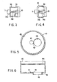
- FIG. 5 is a plan view that shows a blood-sampling chip when viewed from the opening section coupled to a blood-sampling chip connecting section
- FIG. 6 is a cross-sectional view of the blood-sampling chip shown in FIG. 5.
- the following explanation will be given, supposing that a body-fluid inspection device 1 measures the blood-sugar value as one ingredient of body fluids.
- the body-fluid inspection device 1 is shown as being provided with a casing 2, a plunger cover 3, a reduced-pressure releasing button 7 for releasing a reduced pressure state, a blood-sampling chip 10 (coupled to a blood-sampling chip connecting section 8 in FIG. 2), a blood-sampling chip connecting section 8 for securing the blood-sampling chip 10, a blood-sampling chip releasing lever 6 for removing the blood-sampling chip 10, a power switch 4, a display 5 for displaying the results of measurements, and an elastic member 9 for allowing the blood-sampling chip 10 to be engaged and stopped by the connecting section 8 in a vacuumed state.
- a suction sticking mechanism consisting of a lancet 11 having a sticking needle 11a, a lancet holder 12, a first spring 14, a plunger 15, a second spring 16, a gasket 17a, and other members, a measuring mechanism (of which only a photoemmisive means 20 and a photoelectric means 21 are shown), and a display mechanism (not shown).
- the suction/sticking mechanism is constituted by a sticking mechanism and a suction mechanism.
- the sticking mechanism is constituted by the lancet 11 having the sticking needle 11a, the lancet holder 12 for holding the lancet 11, an engaging member 13 that is integral with the lancet holder 12 and has an engaging section 13a at its end, and the first spring 14 for pressing the lancet holder 12 from its rear end face, and these members 11, 12, 13 and 14 are accommodated in a sticking-device housing 22.
- One end of the first spring 14 is secured to the rear end of the lancet holder 12, while the other end is secured to a wall surface inside the sticking-device housing 22.
- an elastic member that can push the lancet holder 12 out such as a rubber member, may be adopted.
- the suction mechanism is, on the other hand, constituted by the plunger 15 and the gasket 17a that is used for allowing the inside wall of the suction housing 23 to slide along the tip end of the plunger 15 in an air-sealed manner, and these members 15 and 17a are accommodated in the suction housing 23.
- the sticking-device housing 22 and the suction housing 23 are installed side by side, and are designed so that the respective inner spaces communicate with each other through a side hole 18.
- the tip end of the sticking-device housing 22 is in an open state, and the blood-sampling chip connecting section 8 is placed along the tip end.
- the rear end thereof is in a closed state, and the first spring 14 connecting to the lancet holder 12 is secured to its inner surface.
- the first spring 14 is fixed between the rear-end face of the sticking-device housing 22 and the lancet holder 12, as shown in FIG. 2. so as to form a structure for pushing the lancet holder 12 out; however, it may be fixed between the tip end of the sticking housing 22 and the lancet holder 12 so as to form a structure for drawing the lancet holder 12 out.
- the suction housing 23 has a communicating hole 19 in its tip end, and the gasket 17a, which slides along the inner wall in an air-sealed state, is sealed inside thereof.
- a non-return valve 32 is installed on the outside section of the suction housing 23 so as to form an evacuation means which, upon a high pressure state inside the sticking-device housing 22 and the suction housing 23, releases air corresponding to the excessive pressure.
- the communicating hole 19 and the non-return valve 32 may be installed on the side face of the suction housing 23.
- the plunger 15, which extends toward the rear end of the suction housing 23, is attached to the gasket 17a.
- an O ring 17b is preferably installed along the circumferential surface of the gasket 17a so as to enhance its sliding property and air-sealing property.
- the sticking-device housing 22 and the suction housing 23 are installed in parallel with each other; however, they may be installed in series with each other.
- a hole, which corresponds to the side hole 18, is formed from the rear end of the sticking-device housing 22 to the tip end of the suction housing 23, and the engaging section 13 is engaged and stopped by this hole, and is released from its engagement by contacting the gasket 17a, with the communicating hole being formed in the side face of the housing.
- the body-fluid inspection device tends to become longer in its entire length; however, it is possible to shorten the entire length by making both or either of the sticking-device housing 22 and the suction housing 23 thicker and shorter, and adjusting the respective components to be housed in the respective housings to corresponding sizes.
- a rod-shaped member is installed in parallel with the sticking-device housing 22 between the outer surface of the sticking-device housing 22 and the inner surface of the casing 2 in such a manner that its one end is secured to the inside of a blood-sampling chip release lever 6 on the surface of the casing 2, while the other end is allowed to stick out by shifting the blood-sampling chip release lever 6, and is further allowed to contact the blood-sampling chip 10 in such a sticking-out state, so as to separate it from the blood-sampling chip connecting section 8.
- cross-sectional shapes of the sticking-device housing 22 and the suction housing 23 are not specifically limited, and may be formed into round, square, or other polygon shapes.
- the gasket 17a is preferably formed into the same shape as the inner-surface shape of the suction housing.
- the blood-sampling chip connecting section 8 is installed in the body-fluid inspection device 1.
- the blood-sampling chip connecting section 8 sticks out from the casing 2 as a cylinder so as to surround the opening of the tip end of the sticking-device housing 22 in the form of double circles, and the blood-sampling chip 10 is fitted thereto in a covering manner.
- a photoemmissive device 20 and a photoelectric device 21 that serve as a measuring mechanism in addition to the tip end of the sticking-device housing 22.
- a ring-shaped elastic member 9 is installed along the outer surface of the blood-sampling chip connecting section 8 in contact therewith so as to positively engage and stop the blood-sampling chip 10 in an air-sealed state.
- the blood-sampling chip connecting section 8 is not intended to be limited to the above-mentioned embodiment.
- it may have a structure that continuously extend from the tip end without surrounding the tip end of the sticking-device housing 22, or is not necessarily provided as a structure that protrudes from the casing 2.
- any structure is adopted as long as it can be fitted to the blood-sampling chip 10 in an air-sealed state, and as long as, when reduced pressure is applied to the sticking-device housing 22 and the suction housing 23 with the skin of a subject being put on a suction opening 43 (see FIG. 5) of the blood-sampling chip 10, the reduced pressure state is maintained.
- the shape of the blood-sampling chip 10 is not intended to be limited to the shape as shown in FIG. 4 or FIG. 5.
- the photoemmissive device 20 and the photoelectric device 21 are installed as a measuring mechanism so that the sugar ingredient in the blood is allowed to develop colors by a color reaction through a method that will be described later, and so that the blood-sugar value is calculated by measuring the degree of light absorption and displayed.
- a conventional blood-sugar calculating means for calculating the blood-sugar value by using a similar means and a conventional display means can be adopted.
- the measuring means is not intended to be limited to a means for allowing the sugar ingredient in the blood to develop colors by a color reaction as will be described later and for measuring the degree of light absorption; and other means for making a direct contact of the sample or for measuring the blood-sugar value by allowing light with a predetermined wavelength to pass through the sample may be adopted.
- a sensor, etc. which is suitable for the means may be used in lieu of the photoemmissive device 20 and the photoelectric device 21.
- FIG. 5 is a plan view that shows the blood-sampling chip 10 that is viewed from an opening 45 that fits to the blood-sampling chip connecting section 8 of the blood-sampling chip 10
- FIG. 6 is a cross-sectional view of the blood-sampling chip 10 shown in FIG. 5.
- the blood-sampling chip 10 which has a cylindrical shape, is provided with a bottom face on its one end in which the suction opening 43 for sucking the skin upon contact with the skin and upon reduced pressure of the sticking-device housing 22 and the suction housing 23 is installed, and an opening 45 on the other end that fits to the blood-sampling chip connecting section 8.
- Test paper 41 used for absorbing body fluids serving as a sample is placed by the side of the suction opening 43 (in the vicinity of the center of the bottom surface), and a groove 42 serving as a body-fluid (blood) guiding means for guiding body fluids from the suction opening 43 to the test paper 41 through the surface tension is also formed.
- the shape, size and length of the groove 42 are not specifically limited; and they are appropriately selected in accordance with the size and shape of the test paper 41 and the suction opening 43.
- the blood-sampling chip 10 is not intended to be limited to the cylinder shape, and may be provided as a square shape in its cross-section, a cylinder having a polygonal shape in its cross-section or a conical shape whose diameter narrows toward its one end.
- the diameter of the suction opening 43 is not particularly limited, and may be set at any size as long as it is larger than a minimum size that allows the sucked skin to form an appropriate mound shape from which blood is absorbed. Further, the shape is not particularly limited, and may be provided as a square or another polygonal shape. Specifically, the suction opening is preferably set so as to have an opening diameter of 4 to 10 mm so as to come into contact with the surface of a living body, such as the finger tip, upper arm, abdomen, thigh, and an ear-lobe and to allow a desired blood absorbing process independent of individual differences such as sex, age, etc.
- the portion to be stuck is an ear-lobe
- it is preferably set in the range of 4 to 6 mm. It is also preferably formed into a shape, such as a pipe shape, which can stimulate the periphery of the portion to be stuck when pressed onto the surface (skin) of a living body. This is because the stimulation on the periphery of the portion to be stuck makes it possible to alleviate pain at the time of sticking.
- a cylinder member 46 is preferably attached to the circumferential edge of the suction opening 43. Moreover, this cylinder member 46 makes it possible to prevent air from flowing into the sticking-device housing 22 and the suction housing 23 through the gap between the blood-sampling chip 10 and the skin when the sticking-device housing 22 and the suction housing 23 are maintained in a reduced pressure state.
- the blood-sampling chip 10 is preferably constituted by a transparent or translucent material.
- the shape and size of the opening 45 are not particularly limited, and any shape and size thereof are used as long as the opening 45 is fitted to the blood-sampling chip connecting section 8 in an air-sealed state. Additionally, it is preferable to form a ring-shaped protrusion 44 along the inner circumferential face of the opening 45; this makes it possible to connect the blood-sampling chip 10 and the blood-sampling chip connecting section 8 more firmly in an air-sealed state by an interactive function with the elastic member 9 installed in the blood-sampling chip connecting section 8.
- the shape and size (including the thickness) of the test paper 41 are not particularly limited; however, when it is too large, there may be a possibility that measurements become inoperative in the case of a small amount of absorbed sample, or when it is too small, the sample might not be absorbed appropriately. Taking these into consideration, the test paper 41 is appropriately selected.
- the position of the test paper 41 is not particularly limited, as long as it is close to the suction opening 43 and allows the measuring mechanism to sense the test paper. In FIGS. 5 and 6, the test paper 41 is located in the vicinity of the center of the bottom face with the suction opening 43 being located on its side; however, the layout may be reversed, or the centers of the test paper 41 and the suction opening 43 may be located in the vicinity of the center of the bottom face.
- the material and mode of the test paper 41 are not particularly limited, and nonwoven fabric, etc. which have been conventionally used as body-fluid testing materials may be utilized. Moreover, since the body-fluid inspection device 1 is designed to measure the blood-sugar value (glucose concentration) by the use of a color reaction, a reagent for allowing an enzyme such as glucose oxidase and/or its decomposed products to develop colors is fixed to the test paper 41.
- the measuring method is not intended to be limited to the measurements of the degree of light absorption by the use of the color reaction, and when another measuring method is used, the measuring mechanism may be provided with another appropriate device, such as a sensor, instead of the above-mentioned photoemmissive device 20 and the photoelectric device 21.
- the communicating hole 19 is formed in the suction housing 23 as one element of the reduced-pressure releasing means for releasing the reduced-pressure state after a reduced pressure has been applied to the sticking-device housing 22 and the suction housing 23 in order to suck the skin and also to suck body fluids.
- the communicating hole 19 also serves as one element of the evacuation means which, in the case of a pressurized state of the sticking-device housing 22 and the suction housing 23 at the time of the sticking process, releases air corresponding to the excessive pressure.
- FIG. 3 shows a cross-sectional view of the suction housing 23 when it is in a normal state or in a reduced-pressure state
- FIG. 4 is a cross-sectional view showing a state in which the suction housing 23 is releasing the reduced-pressure state.
- the reduced-pressure releasing means and the evacuation means are respectively installed in a flexible housing 30.
- the housing 30 is provided with a reduced-pressure releasing button 7 and a vent hole 33.
- the reduced-pressure releasing means is constituted by the communicating hole 19, a driver 31 a having a shape like the tip end of a minus screwdriver and a wedge member 31 b attached to the base end thereof.
- the evacuation means is constituted by the communicating hole 19 and the non-return valve 32.
- the driver 31 a has a needle shape
- the wedge member 31 b consists of several sheets of triangular plates.
- the non-return valve 32 has an opening at the top of its flexible conical body.
- the driver 31 a, the wedge member 31 b and the non-return valve 32 are not intended to be limited to these shapes, and the reduced-pressure releasing means and the evacuation means may be provided as independent parts.
- the reduced-pressure releasing means In the normal state or the reduced-pressure state (FIG. 3) of the suction housing 23, the reduced-pressure releasing means is maintained in a reduced-pressure state since the reversal stopping valve and its opening are sealed with the driver 31 a. Thereafter, when the suction process of the skin becomes unnecessary, the reduced-pressure releasing button 7 is depressed. This allows the driver 31 a and the wedge member 31 b to open the non-return valve 32 in a reverse direction, with the result that air flows into the sticking-device housing 22 and the suction housing 23 from the vent hole 33 via the communicating hole 19, thereby releasing the reduced-pressure state.
- the evacuation means is arranged so that when the sticking-device housing 22 and the suction housing 23 are brought into a pressurized state by sliding the gasket 17a inside the suction housing 23 at the time of sticking, the non-return valve 32 is allowed to open by the pressure so that air corresponding to the excessive pressure is released from the communicating hole 19 via the vent hole 33.
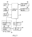
- FIG. 7 shows one example of the body-fluid ingredient measuring circuit of the body-fluid inspection device of the present invention.
- the measuring circuit is provided with a control device 51 such as a CPU, and to the control device 51 are connected a display device 52 (corresponding to the display 5 in FIG. 1), a power-source section 53 (which is connected to the power switch in FIG. 1), a switching circuit 54, a data storage section 55 and an external output section 56.
- an optical sensor 59 constituted by a photoemmissive element 57 (corresponding to the photoemmissive means 20 in FIG. 2) and a photoelectric element 58 (corresponding to the photoelectric means 21 in FIG. 2) is connected to the control device 51.
- the photoemmissive element 57 when driven by a signal from the control device, projects light having a given wavelength onto test paper (not shown) which has absorbed blood, and reflected light is received by the photoelectric element 58.
- the received light is amplified by an amplifier 60, and inputted to the control device through an A/D converter 61; thus, the control device 51 calculates the blood-sugar value from the input signal based upon data stored in the data storage section 55, and allows the display device 52 to display the results.
- the lancet holder 12 After the lancet 11 has been attached to the lancet holder 12, the lancet holder 12 is pushed into the sticking-device housing 22 until the engaging section 13 is engaged by the side hole 18. At this time, the first spring 24 is maintained in a compressed state.
- the blood-sampling chip 10 is attached to the blood-sampling chip connecting section 8 in the main body casing 2. Then, the power switch 4 of the body-fluid inspection device 1 is turned on.
- the power switch may be turned on before the blood-sampling chip 10 has been attached.
- a switch may be designed so as to automatically turn on the power upon attaching the blood-sampling chip 10, and in this case, the power switch 4 is not required.
- the suction opening 43 at the tip of the blood-sampling chip is pressed onto the skin of the subject at a portion to be stuck, and upon pressing the plunger cover 3, the gasket 17a is shifted inside the suction housing 23 in an air-sealed state through the plunger 15 that moves in cooperation with the plunger cover 3.
- the gasket 17a or the O ring 17b pushes the engaging section 13, thereby removing the engagement; thus, the first spring 14, which has been in a compressed state, is released so that the lancet 11 and the lancet holder 12 is allowed to advance toward the suction opening of the blood-sampling chip 10 and carry out a sticking operation.
- the non-return valve 32 is opened by the pressure so that air corresponding to the excessive pressure is released from the communicating hole 19 via the vent hole 33.
- the lancet holder 12 to which the lancet 11 is attached is allowed to return to its original position corresponding to the natural length of the spring by the damping function of the spring.
- the gasket 17a is allowed to retreat by the function of the second spring 16 through the plunger 3 that moves in cooperation with the plunger cover 3, thereby bringing the sticking-device housing 22 and suction housing 23 into a reduced-pressure state so that body fluids are sucked from the stuck portion.
- the minimum pressure inside the space in the reduced-pressure state is preferably set at approximately -300 mmHg with respect to the atmospheric pressure. This makes it possible to suck a required amount of body fluids in a short time. Then, the body fluids sucked onto the skin are transmitted through the guiding groove 42 formed in the inner wall of the blood-sampling chip 10 by the capillary phenomenon, and absorbed into the test paper 41.
- the reduced-pressure releasing button 7 is pressed so that external air is introduced into the sticking-device housing 22 and the suction housing 23, and the body-fluid inspection device 1 is removed when the sense of being sucked disappears from the skin.
- the present invention provides a body-fluid inspection device in which a sticking tool and a measuring device for a body-fluid ingredient (for example, blood-sugar value) are formed into an integral device.
- a sticking tool and a measuring device for a body-fluid ingredient for example, blood-sugar value
- the body-fluid inspection device of the present invention provides an efficient operation and is superior in sanitation.
- the body-fluid inspection device of the present invention carries out a suction operation on the periphery of a portion to be stuck on the skin of the subject, with the inside of the device being maintained in a reduced-pressure state so as to accelerate the flow of body fluids; therefore, even with superficial sticking with less pain, an amount of body fluids required for an inspection, etc., can be readily obtained, and measured.
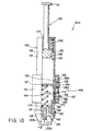
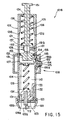
- FIGS. 8, 9, 10 and 11 are cross-sectional side views that show the sticking tool of the present invention in respectively different states; and FIG. 12 and FIG. 13 are cross-sectional views that show a structural example of the air-releasing means.
- the upper side is referred to as "base end” and the lower side is referred to as "tip end”.
- the present sticking tool (blood-sampling sticking tool) 101 A is provided with a housing 102, a sticking plunger 103, a coil spring (first pressing means) 104 for pressing the sticking plunger 103 in the tip-end direction, a suction plunger 105, a coil spring (second pressing means) 106 for pressing the suction plunger 105 in the base-end direction, an air-releasing valve (air-releasing means) 107 and an operation means 108.
- the housing 102 is constituted by a cylinder-shaped housing main body 121 and a cap 122 that is attached to the tip end of the housing main body 121 so as to be freely detached.
- the housing main body 121 and the cap 122 are made of a material that virtually does not transmit air.
- a seal ring 123 made of an elastic material, is inserted and sandwiched between the housing main body 121 and the cap 122 so that the cap 122 is attached to the housing main body 121 in an air-sealed state.
- the housing main body 121 is designed to house the sticking plunger 103 which will be described later in detail, the coil spring 104, the suction plunger 105 and the coil spring 106, and also serves as a holding portion when the sticking tool 101 A is used.
- the cap 122 which is a tube-shaped member, has a taper section 122b that narrows its inner and outer diameters toward the tip end.
- the tip end of the cap 122 is a portion that is to come into contact with the surface of a living body, such as, for example, the finger tip, upper arm, abdomen, thigh or ear-lobe, and is provided with a tip opening 122a.
- This tip opening 122a has its opening diameter (opening area) properly adjusted so that a desired suction blood sampling can be carried out independent of individual differences such as sex, age, etc. and differences in portions to be stuck.
- the opening diameter of the tip opening 122a is preferably set in the range of 4 to 10 mm, and is more preferably set in the range of 4 to 6 mm in the case when the finger or ear-lobe is used as the portion to be stuck.
- the outer edge of the tip end of the cap 122 is formed into a shape that is suitable for stimulating the periphery of the portion to be stuck and for alleviating pain at the time of sticking when it is pressed onto the surface of a living body (the skin).
- the shape is also suitable for preventing air from flowing into the housing 102 between the cap 122 and the surface of a living body when the housing 102 is in a reduced-pressure state.
- the cap 122 is preferably made of a transparent or translucent material.
- An opening 124 through which the suction plunger 105 is inserted is formed at the base end of the housing main body 121.
- side holes 125 and 126 which respectively correspond to a sticking- and suction-use operation button 184 and an air-releasing-use operation button 186 that will be described later, are formed in the side wall of the housing main body 121.
- a partition plate 127 is placed inside the housing main body 121.
- the partition plate 127 is fixedly secured to the side wall of the housing main body 121, or is integrally formed therewith.
- a guide groove 128 is formed in the side-wall inner surface of the housing main body 121 in the length direction of the housing main body 121.
- a stopper 129 with which a protruding portion 134 comes into contact is formed at the tip end of the guide groove 128 (see FIG. 9).
- a sticking mechanism constituted by the sticking plunger 103 and the coil spring 104 for pressing the sticking plunger 103 toward the tip end, is placed inside the housing main body 121.
- the sticking plunger 103 is constituted by a needle holder (lancet holder) 131 to which the lancet 111 having the sticking needle 112 is detachably attached, an elastic member 132 that is integrally formed with the needle holder 131 with a first engaging section 133 provided at its end (on the base-end side), and a protruding portion 134 that is integrally formed with the needle holder 131.
- the first engaging section 133 is pressed to the right in FIG. 8 by the elastic force of the elastic member 132, and is engaged by the edge of the side hole 125; thus, the sticking plunger 103 is restricted in its shift toward the tip end.
- the coil spring 104 When the sticking tool 101 A is not used (in a state prior to sticking), the coil spring 104 is in a compressed state, and its respective ends are secured to the partition plate 127 and the base-end face of the needle holder 131 so that the sticking plunger 103 is pressed toward the tip end.
- the protruding portion 134 is inserted into the guide groove 128, and allowed to slide in the length directions of the guide groove 128.
- the sticking plunger 103 is shifted inside the housing 102.
- the protruding portion 134 comes into contact with the stopper 129, thereby restricting the sticking plunger 103 in its shift toward the tip end.
- the coil spring 104 is properly set so as to have an appropriate elastic coefficient (spring constant) so as not to again stick the surface of a living body during its damping movements after the sticking needle 112 has stuck the surface of the living body.
- a suction mechanism (negative-pressure generation mechanism), which is constituted by the suction plunger 105 and the coil spring 106 for pressing the suction plunger 105 toward the base end, is installed in the housing main body 121.
- the suction plunger 105 is a rod-shaped member, and provided with a handling section 151 on its base end and a gasket 152 on its tip end.
- the gasket 152 has a seal ring (sealing member) 153 made of an elastic material along its peripheral portion.
- the seal ring 153 contacts the inner circumferential face of the housing main body 121 in an air-sealed state, and when the suction plunger 105 is shifted in a length direction of the housing main body 121, the seal ring 153 also shifts in the same direction along the inner circumferential face of the housing main body 121 in an air-sealed state.
- the seal ring 153 is preferably set to exhibit a sliding resistance to a degree not to disturb the expansion and shrinkage of the coil spring 106.
- An elastic member 154 which is elastically deformable, is formed on the side face of the gasket 152 in a protruding manner, and a second engaging section 155 is formed on its tip end.
- the second engaging section 155 is pressed to the right in FIG. 8 by the elastic force of the elastic member 154, and is engaged by the edge of the side hole 125; thus, the suction plunger 105 is restricted in its shift toward the base end.
- the respective ends of the coil spring 106 are fixed to the base end of the housing main body 121 and the gasket 152.
- the coil spring 106 is in an extended state so that the suction plunger 105 is pressed toward the base end by its elastic force.
- the seal ring 153 of the gasket 152 contacts the inner circumferential face of the housing main body 121 in an air-sealed state, and the side holes 125 and 126 are also sealed in an air-sealed state; therefore, when the suction plunger 105 is shifted toward the base end with the tip opening 122a being sealed on the surface of a living body, a space 110 inside the housing 102, surrounded by the housing 102 and the gasket 152, is brought to a reduced-pressure state (negative-pressure state).
- the air-releasing means is used for releasing the space 110 inside the housing 102 kept in the reduced-pressure state to the atmospheric pressure, and in the present embodiment, it is provided as an air-releasing valve 107 that is manually opened and closed.
- the air-releasing valve 107 is constituted by a disc-shaped valve member 171 that is connected to or integrally formed with the shaft 186a of the operation button 186, an elastic member 172 which has a C-lefter shape (a shape of a ring with a cut-out in its one portion) and presses the operation button 186 and the valve member 171 to the right in FIG. 1, and a ring-shaped seal pad (seal member) 173 which is secured to the valve member 171 and made of an elastic material.
- the elastic member 172 is set so as to have an appropriate elasticity (rubber hardness) so that it is hardly deformed when the space 110 is brought to a reduced-pressure state by the operation of the suction plunger 105 and a force is exerted on the valve 171 to the left in FIG. 8 due to the pressure difference over the atmospheric pressure, and so that upon depression of the operation button 186 by the finger, etc., a predetermined amount of deformation is made, thereby allowing the seal pad 173 to separate from the inner face of the housing main body 121 on the periphery of the side hole 126 and to form the gap.
- an appropriate elasticity rubber hardness
- the constituent material of the elastic member 172 for example, the following materials are listed: various rubber materials, such as natural rubber, isoprene rubber, butadiene rubber, styrene-butadiene rubber, nitril rubber, chloroprene rubber, butyl rubber, acrylic rubber, ethylene-propylene rubber, hydrine rubber, urethane rubber, silicone rubber and fluorine-containing rubber, and various elastmers, such as styrene, polyolefin, polyvinyl-chloride, polyurethane, polyester, polyamide, polybutadiene and fluorinated elastmers. Further, various springs such as coil springs may be used as the elastic member 172.
- various rubber materials such as natural rubber, isoprene rubber, butadiene rubber, styrene-butadiene rubber, nitril rubber, chloroprene rubber, butyl rubber, acrylic rubber, ethylene-propylene rubber, hydrine rubber, urethan
- the operation means 108 carries out the following operations: (1) a sticking operation which is made by the sticking needle 112 on the surface of a living body through the operation of the sticking plunger 103; (2) a pressure-reducing operation applied to the space 110 by the operation of the suction plunger 105; and (3) a releasing operation applied to the space 110 so as to release the reduced-pressure state to the atmospheric pressure.
- It is constituted by a cover (case) 181 for housing the housing main body 121, the sticking- and suction-use operation button 184, the pressing member 185 and the air-releasing operation button 186.
- the cover 181 also has a function for housing and maintaining the operation buttons 184 and 186.
- button-inserting holes 182 and 183 are formed in the cover 181 so that the operation button 184 and the operation button 186 are respectively inserted through the button-inserting hole 182 and the button-inserting hole 183.
- the pressing member 185 placed on the backside of the operation button 184, is constituted by a plate-shape member made of an elastic material such as a rubber material, and is fixedly bonded from the outside of the housing 121 in a manner so as to seal the side hole 125 in an air-sealed manner. Therefore, the pressing member 185 also has a function as a sealing member.
- first protruding portion 185a Inside the pressing member 185 are formed a first protruding portion 185a and a second protruding portion 185b that protrude toward the inside of the side hole 125.
- the first protruding portion 185a contacts the first engaging section 133, and the second protruding portion 185b contacts the second engaging section 155.
- the height (the length of protrusion) of the first protruding portion 185a is set to be greater than the height (the length of protrusion) of the second protruding portion 185b.
- the pressing member 185 is deformed in cooperation with the pressing operation of the operation button 184 in a lateral direction in FIG. 8. More specifically, when the operation button 184 is pressed to the left in FIG. 8 by the finger, etc., with the first engaging section 133 and the second engaging section 155 being engaged by the edge of the side hole 125 (see FIG. 8), the pressing member 185 is also depressed in the same direction so that the first protruding portion 185a and the second protruding portion 185b are deformed so as to protrude further into the side hole 125 (see FIGS. 9 and 10). Consequently, the first engaging section 133 and the second engaging section 155 are pressed to the left in FIGS.
- the pressing direction of the operation button 184 that is, the operation direction in which the sticking plunger 103 is operated and allowed to stick
- the shifting direction (the sticking direction) of the sticking plunger 103 are set in different directions (directions virtually orthogonal to each other). This makes it possible to alleviate fear of the sticking operation, and also to keep unchanged the contact pressure of the tip end of the cap 122 onto the surface of a living body applied by the pressing force of the operation button 184, thereby ensuring a predetermined depth of the sticking operation.
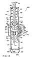
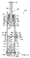
- FIGS. 14 through 17 are cross-sectional side views that respectively show another embodiment of the sticking tool of the present invention
- FIGS. 18 through 21 are cross-sectional views that respectively show a structural example of an air-releasing means.
- sticking tool 101 B shown in these drawings based upon distinctions from the above-mentioned sticking tool 1 01 A, and with respect to the same operations, the description thereof is omitted.
- base end the upper side
- tip end the lower side
- the sticking tool 101 B is provided with an air-releasing means which is automatically operated in accordance with the shift of the suction plunger 105 toward the base end.
- the plunger 105 in the sticking tool 101 B is provided with an inner space (vent path) 156 that penetrates from its base end to its tip end. Moreover, a flange 157 is formed at a position on the base end side from the air-releasing valve 109 of the suction plunger 105, and the tip end of the coil spring 106 is secured to the flange 157.
- the air-releasing valve (air-releasing means) 109 is installed in the suction plunger 105.
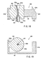
- the air-releasing valve 109 is constituted by an operation member 191 having an inverted letter C-shape when viewed from the top, a seal member 192 secured to one end of the operation member 191 and a tube body 193 having a vent inlet 193d.
- a head portion 191 a is attached to the other end of the operation member 191, and a slanting slope 191 b is formed in the head portion 191 a.
- the seal member 192 is made of an elastic material as described earlier, and a vent path 192a having a narrow-diameter section is formed in the center thereof. As illustrated in FIG. 18, the upper end of the vent path 192a communicates with an inner space 156 formed in the suction plunger 105 on the base-end side from the flange 157.
- a fitting section 192b is formed in the seal member 192, and the fitting section 192b is fitted to one end of the operation member 191 and fixedly bonded thereto.
- the tube body 193, which is inserted into the vent path 192a, is provided with a small-diameter section 193a and a large-diameter section 193b, and a taper section 193c that connects these sections.
- a vent opening 193d which allows the inside and outside of the tube body 193 to communicate with each other is formed in the taper section 193c.
- the small-diameter section 193a and the taper section 193c of the tube body 193 closely contact the inner face of the vent path 192a with the seal member 192 sandwiched along all circumferential area thereof (see FIG. 18 and FIG. 19).
- the end of the large-diameter section 193b of the tube body 193 is inserted into the inner space 156 formed inside the gasket 152 so that the inside of the tube body 193 and the inner space 156 are allowed to communicate with each other.
- a fine flow-path 193e for ensuring a fine amount of ventilation is formed inside the small-diameter section 193a of the tube body 193.
- the fine flow-path 193e communicates with the vent path 192a.
- any of hard materials such as a hard resin and a metal material, soft materials such as a soft resin and elastic materials as described earlier, may be applied; however, it is preferable to use hard or soft resin materials.
- the small-diameter section 193a and the taper section 193c of the tube body 193 closely contact the inner face of the vent path 192a with the seal member 192 sandwiched along all the circumferential area thereof. This blocks the vent opening 193d, making a state in which the inner spaces 56 are virtually shielded from the air flow (a state in which the air-releasing valve 109 has been closed).
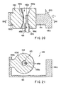
- the inner spaces 156 at the respective ends of the air-releasing valve 109 are allowed to communicate with each other through the vent path 193a, the vent opening 193d and the inside of the tube body 193 so that air flow is available.
- the air-releasing valve 109 is opened in a reduced-pressure state of the space 110, air flows into the space 110 through paths indicated by arrows in FIG. 20.
- the air-releasing valve 109 also serves as a relief valve which, upon having a pressurized state in the space 110 due to the shifting operation of the suction plunger 105 toward the tip end, releases air corresponding to the excessive pressure.
- the air-releasing valve 109 being closed (a state shown in FIG. 18 and FIG. 19)
- the air inside the space 110 is externally released through the fine flow-path 193e of the tube body 193 little by little.
- a slanting face (cam face) 121 a which engages the slanting face 191 b of the head section 191 a, is formed in the inner face on the base-end side of the housing main body 121.
- a step-gap section 121 b is formed in the inner face on the base-end side of the housing main body 121, which is the side opposite to the slanting face 121 a.
- the step-gap section 121 b engages the outer circumferential portion on the base-end side of the gasket 152 so as to restrict the shift of the suction plunger 105 toward the base end.
- the opening of the air-releasing valve 109 which is made when the slanting face 191 b passes through the slanting face 121 a, takes place immediately before the gasket 152 is engaged by the step-gap section 121 b, that is, immediately before the suction plunger 105 has arrived at the limit position of shift on the base-end side.
- the time that is taken from the release of the engaging section 155 from the edge of the side hole 125 to the opening of the air-releasing valve 109 is set as a time period that sufficiently allows an amount of blood required to be sucked through the portion that has been stuck by the sticking needle 112; and, for example, this is preferably set in the range of 3 to 10 seconds.
- This time can be set appropriately by selecting factors, such as the spring elasticity of the coil spring 106, the sliding resistance of the seal ring 153 against the inner face of the housing main body 121, the shift stroke of the suction plunger 105 and the installation position of the slanting face 121 a.
- the time can also be adjusted by exchanging the coil spring 106 and/or the seal ring 153.
- a stopper 129a with which the tip face of the needle holder 131 comes into contact is formed in the inner face of the tip end of the housing main body 121.
- the stopper 129a is secured to the inner surface of the housing main body 121, for example, by means of threads, and can be adjusted in its position in the length direction with respect to the housing main body 121 by the amount of revolutions of the threads. In this manner, the amount of protrusion of the sticking needle 112, that is, the depth of sticking into the surface of a living body, can be adjusted depending on individual differences in the person whose blood is to be sampled (the subject) and differences in the portion to be stuck.
- the gear structure of a micrometer may be adopted.
- the pressure inside the housing 102 is automatically returned to the atmospheric pressure, without the need for the operation of the person whose blood is to be sampled (the subject), etc.; therefore, it is possible to reduce dispersions in the amount of sampled blood resulting from an erroneous judgement on the timing for the return to the atmospheric pressure, and also to prevent scattering of blood due to the fact that the operator forgot to return the pressure to the atmospheric pressure. Consequently, a more appropriate blood inspection is available.
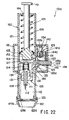
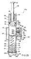
- FIGS. 22 through 25 are cross-sectional side views that respectively show another embodiment of the sticking tool of the present invention.
- sticking tool 101C shown in these drawings based upon distinctions from the above-mentioned sticking tool 101 A, and with respect to the same operations, the description thereof is omitted.
- base end the upper side
- tip end the lower side
- the sticking tool 101C makes it possible to carry out the sticking operation by the use of the sticking needle 112, the suction operation (reduction of the pressure in the space 110) and the releasing operation of the space 110 to the atmospheric pressure in this order.
- the branch path 194 is housed in the cover 181.
- the air-releasing valve (air-releasing means) 109 which is the same as that of the sticking tool 101 B is installed at the end of the branch path 194 in a manner so as to seal (shield) the inside of the branch path 194.
- a lever 184a is attached to the operation button 184 in a manner so as to stick in a direction orthogonal to the shifting direction of the operation button 184.
- the sticking tool 101C is provided with the same stopper 129a as described earlier on the inside of the tip end of the housing main body 121.
- the sticking tool 101C merely by pressing the operation button 184, it is possible to carry out the sticking operation by the use of the sticking needle 112, the suction operation and reduction of the pressure in the space 110 and the releasing operation of the space 110 to the atmospheric pressure in this order; this ensures superior operability.
- the sticking tools of the present invention are not intended to be limited thereby.
- they may be used for sampling body fluids other than blood, such as inter-organ fluids, and the application is not particularly limited.
- the suction process is carried out on the periphery of the portion that has been stuck so as to accelerate the flow of body fluids (bleeding); therefore, it is possible to ensure to obtain an amount of body fluids required for an inspection, etc. quickly, even if only a shallow sticking is made so as to reduce pain.
- the mechanism for releasing the inside of the housing so as to return the pressure to the atmospheric pressure after the suction process is provided; therefore, it is possible to prevent scattering of the body fluids due to a rapid air flow occurring in the proximity of the portion that has been stuck.
- an air-releasing operation is carried out without the need for the shift of the sticking needle (coming close to the surface of a living body), it is possible to prevent an erroneous sticking recurring on the surface of the living body, and consequently to provide a highly safe device.
- the sticking operation and the suction operation are carried out in this order or at the same time, and the air-releasing operation is then carried out successively.
- the depth of sticking can be appropriately adjusted depending on various conditions, such as individual differences and differences in the portion to be stuck, and every time a body-fluid sampling (blood sampling) operation is performed, a constant depth of sticking is provided.
- preparation operations prior to use that is, operations for setting the sticking plunger and suction plunger in an operative state, are simple and easy; this is advantageous when the device is used regularly or repeatedly.
- the sticking needle is designed not to protrude from the tip opening except for the sticking operation, it is possible to prevent accidents such as an erroneous sticking; this ensures a highly safe device.
- the sticking needle is not directly visible, it is possible to alleviate fear of sticking.
- the sticking tool of the present invention is suitable for cases in which the patient measures his or her own blood-sugar value, etc.
- the sticking tool of the present invention has a simple structure and is suitable for mass production.
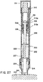
- a sticking tool 201 whose cross-section is shown in FIG. 26 is mainly used for sampling a fine amount of body fluids, such as blood, from the surface of a living body.
- the sticking tool 201 is constituted by a housing 202, a plunger 203 which slides inside the housing 202, a lancet 204 which is attached to the tip end of the plunger 203 and has a sticking needle 241 that extends toward the tip end, a stopper 205 connected to the rear end of the plunger 203, an adjusting mechanism 210 that contacts the stopper 205, and a sticking-use spring 206 used for shifting the plunger 203, the lancet 204 and the stopper 205 toward the tip.
- An engaging section 8 is installed on the inner face of the housing 202, and a stopping section 207, which engages the engaging section 208 so as to stop the plunger 203, the lancet 204 and the stopper 205 at a first position, is installed in the plunger 203.
- the first position refers to a state prior to the sticking operation onto the surface of a living body, and is shown in FIG. 26 more specifically.
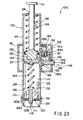
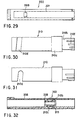
- the shape of the housing 202 is not particularly limited as long as it has a cylindrical shape as shown in FIG. 26; however, from the viewpoint of ease of gripping, it is preferable to provide it as a cylinder. Moreover, it is more preferable to provide a flat section 221 shown in a plan view of FIG. 29 on the periphery of the engaging section 208, because the engagement between the stopping section 207 and the engaging section 208 can be easily released without the need for observing it, merely by sliding the finger along the flat section 221.
- the sticking-use spring 206 one end of which is connected to the plunger 203 and the other end of which is connected to a sticking-use spring fixing base 209 installed inside the housing, is inserted in a compressed state.
- the present invention is not intended to be limited to this structure, and one end may be connected to the lancet 204 or the stopper 205, while the other end may be directly connected to the inner face of the housing 202.
- any spring may be used as long as it allows the plunger 203, lancet 204 and stopper 205 to shift to the first position to the second position, and the shape thereof is not particularly limited; for example, in addition to a coil-shape spring as shown in the drawing, a plate-shape spring, etc. may be adopted, and the material thereof is not particularly limited.
- the sticking-use spring 206 is in a compressed state.
- the second position refers to a position at which the sticking needle 241 sticks the surface of a living body
- the state is not limited to a state in which the sticking needle protrudes from the tip end of the sticking tool 201 and, for example, it includes a state in which the tip end of the sticking tool 201 is pressed onto the surface of a living body so as to be ready for sticking, with the surface of the living body swells inside the tip end.
- the stopping section 207 is installed in the plunger 203; however, the present invention is not intended to be limited to this structure, and it may be installed in the lancet 204 or the stopper 205.
- a shape such as a U-letter shape or a V-letter shape, for allowing both of the ends to be secured to the plunger 203, etc. may be adopted.
- any shape may be adopted as long as the plunger 203, the lancet 204 and the stopper 205 are stopped at the first position by the engagement with the engaging section 208 and the engagement with the engaging section 8 can be released by a movement.
- the stopping section 207 it is preferable to design the stopping section 207 so that one portion thereof protrudes from the outer face of the housing 202 through the engaging section 208, from the viewpoint of the operation for releasing the engagement.
- the engaging section 208 is not particularly limited as long as it engages the stopping section 207 installed on the inner face of the housing 202; however, it is preferable to provide it as a hole penetrating the housing 202 from the inner face to the outer face as is shown in the present embodiment. With this structure, it is possible to ensure the engagement with the stopping section 207, and also to easily release the engagement by pushing the stopping section 207.
- the stopper 205 is connected to the rear end of the plunger 203 and provided with a stopper-side shift restriction mechanism 251.
- the stopper-side shift restriction mechanism 251 engages an adjustment-mechanism-side shift restriction mechanism 210a so that the plunger 203, the lancet 204 and the stopper 205, which have shifted from the first position, are stopped at the second position.
- the stopper-side shift restriction mechanism 251 and the adjustment-mechanism-side shift restriction mechanism 101 are both provided as protrusions; however, the structures are not particularly limited, and another structure may be adopted in which one is provided as a protrusion and the other is provided as a recess, or in which the inner diameter or the outer diameter is gradually changed in the axial direction in both of the mechanisms so that they make a taper-shape engagement.
- the stopper 205 is not necessarily provided as a member separated from the plunger 203 as described in the present embodiment, and it may be provided as an integral part of the plunger 203.
- a shock which is transmitted to the lancet when the plunger 203, the lancet 204 and the stopper 205 have been stopped at the second position from the first position, can be damped by the stopper 205.
- the shock is not directly transmitted to the lancet; therefore, it is possible to prevent an accidental separation of the sticking tool 1 from the hand of the operator by the shock, trembling of the sticking operation and unnecessary pain being given to the person whose body fluids are sampled.
- any mechanism can be adopted as long as it is movable in the axial direction inside the housing 202 as shown in FIG. 26, with the stopper 205 being allowed to move inside thereof, and more specifically, one having a cylinder shape may be adopted.
- the above-mentioned adjustment-mechanism-side shift restriction mechanism 210a is installed in the adjustment mechanism 210.
- the uninserted portion 210b is preferably covered with a protection cover 211 so as to prevent the adjustment mechanism 210 from being shifted from the set position due to an erroneous operation.
- the protection cover 11 is preferably designed so as to have a structure and a material property in which the uninserted portion 210b is not rotated unless the operator intends to do so. For example, it may be removable upon operation of the uninserted portion 210b or it may have flexibility so as to allow the operator to pinch the uninserted portion 210b and to axially rotate it.
- the adjustment mechanism 210 has a structure whose front view is shown in FIG. 30 and whose plan view is shown in FIG. 31. Specifically, a helical groove 210d is formed on the peripheral portion thereof. This groove 210d allows a protruding member 212b installed in a connecting section which will be described later to relatively move along the inside thereof.
- the adjustment mechanism 210 extends in the rear-end direction from the sticking-use spring fixing base 209 installed on the inner face of the housing 202, and is fitted to the connecting section 212 which has a cylinder shape so as to allow the stopper 205 to slide therein.
- the connecting section 212 is provided with the protruding member 212b whose plan view is shown in FIG. 34 and whose left side view is shown in FIG. 36, and a fixing protrusion 212c whose bottom view is shown in FIG. 35.
- the adjustment mechanism 210 When the adjustment mechanism 210 is axially rotated, the protruding member 212b relatively moves inside the groove 210d, thereby allowing the adjustment mechanism 210 to move in the axial length direction.
- the fixing protrusion 212c can fix the state of the adjustment mechanism 210 at the predetermined second position of the plunger, etc. by engaging the recess 210e formed in the inner face of the adjustment mechanism 210.
- the fixing protrusion 212c is not necessarily placed diagonally to the protruding member 212b, and not limited to one position, it may be placed at a plurality of positions.
- the shift range of the stopper 205, etc. from the first position to the second position is indicated by the position of the adjustment mechanism 210 in the length direction and distance X (see FIG. 26) from plane A (see FIG. 26) of the stopper-side shift restriction mechanism 51 and plane B (see FIG. 26) of the adjustment-mechanism-side shift restriction mechanism 210a.
- FIG. 37 shows a state in which the shift range from the first position to the second position is small
- FIG. 38 shows a state in which the shift range from the first position to the second position is large.
- the position of the adjustment mechanism 210 in the length direction is determined by the position of the protruding member 212b of the connecting section 212 inside the helical groove 210d of the adjustment mechanism 210, which is given by axially rotating the adjustment mechanism 210.
- distance X is adjusted and determined by axially rotating the adjustment mechanism 210.
- the following description will discuss the relationship between the recess 210e formed in the inner face of the adjustment mechanism 210 and the fixing protrusion 212c that is placed in the connecting section 212 more specifically.
- the difference in positions of the helical groove 210d in the axial length direction of the adjustment mechanism 210 (the difference between the state having a large range from the first position to the second position and the state having a small range from the first position to the second position) is set at 1 mm, and that five recesses 210e are formed in the inner face of the adjustment mechanism 210 with equal intervals (with 45-degree intervals around the central axis in the length direction of the sticking tool 201).
- distance X can be adjusted by 0.25 mm for each step.
- distance X can be adjusted not at equal intervals, but at predetermined values such as 0.1 mm, 0.2 mm, 0.3 mm and 0.4 mm.
- a mark 210f on the uninserted portion 210b so as to allow visual confirmation of a set value that is to be adjusted by the adjustment mechanism 210.
- the connecting section 212 is preferably provided with one or two or more slits 212a that extend in the length direction.
- the installation of the slits 212a makes it possible to accept a distortion that occurs inside the adjustment mechanism 210 when the stopper-side shift restriction mechanism 251 and the adjustment-mechanism-side shift restriction mechanism 210a come into contact with each other.
- the adjustment mechanism 210 is connected through the connecting section 212 so that the connection of the adjustment mechanism 210 is made with a space 213 between the outer face of the adjustment mechanism 210 from at least the vicinity of the adjustment-mechanism-side shift restriction mechanism 210a to the tip end and the inner face of the housing.
- the space 213 makes it possible to accept a distortion that occurs outside the adjustment mechanism 210 when the stopper-side shift restriction mechanism 251 and the adjustment-mechanism-side shift restriction mechanism 210a come into contact with each other.
- this arrangement in the same manner as the installation of the slits 212a in the connecting section 212 as described above, it is possible to reduce vibration that occurs in the entire structure of the sticking tool 201 when the stopper-side shift restriction mechanism 251 and the adjustment-mechanism-side shift restriction mechanism 210a come into contact with each other. Therefore, it becomes possible to prevent an accidental separation of the sticking tool 201 from the hand of the operator by the vibration, trembling during the sticking operation and unnecessary pain being given to the person whose body fluids are sampled.
- an outer diameter section 210c which is virtually identical to the inner diameter of the housing 202 is preferably attached to the adjustment mechanism 210; thus, it becomes possible to axially rotate the adjustment mechanism 210 stably even with the space 213.
- the connecting section 212 is not necessarily provided, and another structure may be provided in which a protruding member corresponding to the protruding member 212b is attached to either one of the inner face of the housing 202 and the outer face of the adjustment mechanism 210 and a helical groove corresponding to the helical groove 210d is formed in the other so that the position of the adjustment mechanism 210 is adjusted by axially rotating the adjustment mechanism.
- a cap 214 on the tip end of the housing 202.
- the installation method of the cap 214 and the housing 202 is not particularly limited, and a snap-in method and a screwing method by using threads are listed so as to allow easy removal.
- an opening 214a is formed in the contact face to the surface of a living body of the cap 214, and its diameter is set in the range of not less than 1 mm to not more than 10 mm, and more preferably in the range of not less than 1 mm to not more than 6 mm, so as to carry out the sticking operation without limiting the portion to be stuck.
- the cap may have another structure as indicated by a cap 214b whose cross-sectional view of the tip portion is shown in FIG. 39.
- the cap 214b houses a lancet 204b which can slide inside thereof and to which a sticking needle 241 b is connected.
- the cap 214b makes it possible to connect the other end of the lancet 204 to the plunger 203 when the cap 214b is connected to the housing 202b; thus, the same application as described in an explanation of the application of the present embodiment that will be given later is available.
- the plunger 203 it is preferable to respectively provide an axial direction groove 222 in the inner face of the housing 202 and a tremble-preventing protrusion 231 on the plunger 203.
- the tremble-preventing protrusion 231 shifts along the axial direction groove 222 so that the plunger 203 is allowed to move only in the axial direction in a stable manner without trembling in the axial rotation direction; therefore, this allows the sticking needle 241 to stick at an accurate position.
- the materials of the above-mentioned constituent parts are not particularly limited, and they are appropriately selected from hard plastics, metals, etc.
- a material such as a thermoplastic elastomer and rubber, which can maintain the sliding face in an air-sealed state.
- a suction means may be preliminarily provided so that the space inside the housing 202, formed by the plunger 203 and the tip end sealed by the surface of a living body, is brought to a reduced-pressure state, thereby making the surface of the living body swell into the housing 202. Then, the swelled surface may be stuck with the sticking needle 241 so as to effectively suck body fluids to be sampled.
- the operator removes the protection cover 211, and sets the second position of the plunger 203, the lancet 204 and the stopper 205 which allows to suck a minimum amount of body fluids such as blood required for an inspection, that is, the shift distance of the sticking needle 241.
- a minimum amount of body fluids such as blood required for an inspection
- the adjustment mechanism 210 it is not necessary to frequently reset the setting; therefore, the use of the protection cover 11 makes it possible to prevent the sticking needle from being stuck deeper due to an erroneous change in the depth of sticking, erroneous blood sampling, and other misoperations.
- the lancet 204 having the sticking needle 241 is attached to the tip end of the plunger 203, and the plunger 203 with the lancet 204 attached thereto is pushed toward the rear end against the elastic force of the sticking-use spring 206 so that the stopping section 207 is engaged by the edge of the engaging section 208.
- the sticking-use spring 206 is maintained in a compressed state.
- the opening 214a of the tip end of the cap 214 is pressed onto the surface of a living body such as the finger tip, and the stopping section 207 protruding from the engaging section 208 is pressed.
- the stopper 205 slides inside the housing 202 together with the plunger 203, the stopper-side shift restriction mechanism 251 of the stopper 205 comes into contact with the adjustment-mechanism-side shift restriction mechanism 210a of the adjustment mechanism 210 so that the shift of the plunger 203 toward the tip end is restricted; thus, the depth of sticking by the sticking needle 241 of the lancet 204 onto the surface of a living body is adjusted to a predetermined depth.
- the sticking-use spring 208 returns to its natural length through damping movements, and the sticking needle is drawn from the surface of the living body and stored in the housing 202 (see FIG. 28).
- the sticking tool 201 is designed so that the lancet 204 does not protrude from the opening 214a of the tip end of the cap 214 except that it is used for the sticking operation; therefore, it is possible to prevent the sticking needle from erroneously hurt the skin, etc., to prevent contagion, etc., and also to provide a highly safe device.
- the sticking operation can be performed onto the predetermined sticking position with high reproducibility.
- the sticking tool of the present invention is provided with the mechanism for adjusting the depth of sticking by the lancet; this allows the operator to set the depth of sticking suitable for obtaining a minimum amount of blood required for an inspection, and makes it possible to reduce a pain accompanying the sticking operation to a minimum level required.
Abstract
Description
a stopping section is formed in at least one of the lancet, the plunger and the stopper, the stopping section being allowed to engage the engaging section so as to stop the lancet, the plunger and the stopper at a first position; and after the lancet, the plunger and the stopper have shifted toward the tip end from the first position by the spring that is released from the engagement between the engaging section and the stopping section, the stopper comes into contact with the adjustment mechanism so that the shift of the lancet, the plunger and the stopper is stopped at a second position.
Claims (8)
- A sticking tool for sticking into a surface of a body, comprising:wherein: the adjustment mechanism is allowed to move in an axial direction inside the housing, and the stopper is provided so as to slide inside the adjustment mechanism,a housing having a tip end that is opened,a plunger to which a lancet having a sticking needle extending toward the tip end is attached, the plunger being allowed to slide inside the housing,a stopper connected in the rear end direction of the plunger;an adjustment mechanism which contacts the stopper; anda sticking-use spring for shifting the lancet, the plunger and the stopper toward the tip end of the housing, the sticking-use spring being connected to the plunger or the stopper,
an engaging section is provided in the inner face of the housing;
a stopping section is formed in at least one of the lancet, the plunger and the stopper, the stopping section being allowed to engage the engaging section so as to stop the lancet, the plunger and the stopper at a first position; and after the lancet, the plunger and the stopper have shifted toward the tip end from the first position by the spring that is released from the engagement between the engaging section and the stopping section, the stopper comes into contact with the adjustment mechanism so that the shift of the lancet, the plunger and the stopper is stopped at a second position. - The sticking tool according to claim 1, characterized in that at least one portion of the adjustment mechanism has a cylinder shape, the stopper being allowed to slide inside the cylinder of the adjustment mechanism, and a protrusion shift-restricting mechanism for the stopper is installed in both the inside of the cylinder and the stopper.
- The sticking tool according to claims 1 or 2, characterized in that at least not less than one fixing means is provided in the adjustment mechanism and the housing, the fixing means being allowed to stop the adjustment mechanism at a predetermined second position upon adjusting the second position by axially rotating the adjustment mechanism centered on a length-wise axis.
- The sticking tool according to claim 1, characterized in that the second position is adjusted by axially rotating the adjustment mechanism centered on a length-wise axis inside the housing.
- The sticking tool according to claim 1, characterized by further comprising a connecting section that is secured to the housing and extends in the axial direction inside the housing, the adjustment mechanism being fitted in a manner so as to cover the connecting section, a helical groove installed in at least one of the adjustment mechanism and the connecting section, and a protrusion that is formed on the other so as to shift along the helical groove, wherein the second position is adjusted by axially rotating the adjustment mechanism centered on a length-wise axis inside the housing by using the protrusion shifting along the groove.
- The sticking tool according to claim 1, characterized in that: the adjustment mechanism is inserted into the housing from the rear end section of the housing, with an uninserted portion left behind; the adjustment mechanism is axially rotated centered on a length-wise axis inside the housing by axially rotating the uninserted portion centered on thel length-wise axis; and a cover for protecting the uninserted portion is installed on the rear end portion of the housing.
- The sticking tool according to claim 1, characterized in that at least one portion of the adjustment mechanism has a cylinder shape, the stopper being allowed to slide inside the cylinder of the adjustment mechanism, and a shift-restricting mechanism for the stopper is installed in both or either of the inside of the cylinder and the stopper.
- The sticking tool according to claim 7, characterized in that one or not less than two slits that extend in the axial length direction are formed in the cylinder.
Applications Claiming Priority (7)
| Application Number | Priority Date | Filing Date | Title |
|---|---|---|---|
| JP2509198 | 1998-01-22 | ||
| JP10025091A JPH11206742A (en) | 1998-01-22 | 1998-01-22 | Piercing tool |
| JP10183794A JP2000014662A (en) | 1998-01-22 | 1998-06-30 | Humor examination device |
| JP18379498 | 1998-06-30 | ||
| JP29632598 | 1998-10-19 | ||
| JP29632598A JP3902875B2 (en) | 1998-10-19 | 1998-10-19 | Puncture device |
| EP99400147A EP0931507B1 (en) | 1998-01-22 | 1999-01-22 | Body-fluid inspection device |
Related Parent Applications (2)
| Application Number | Title | Priority Date | Filing Date |
|---|---|---|---|
| EP99400147.7 Division | 1999-01-22 | ||
| EP99400147A Division EP0931507B1 (en) | 1998-01-22 | 1999-01-22 | Body-fluid inspection device |
Publications (2)
| Publication Number | Publication Date |
|---|---|
| EP1609416A2 true EP1609416A2 (en) | 2005-12-28 |
| EP1609416A3 EP1609416A3 (en) | 2014-03-26 |
Family
ID=27284890
Family Applications (3)
| Application Number | Title | Priority Date | Filing Date |
|---|---|---|---|
| EP05020686.1A Withdrawn EP1609416A3 (en) | 1998-01-22 | 1999-01-22 | Body-fluid inspection device |
| EP99400147A Expired - Lifetime EP0931507B1 (en) | 1998-01-22 | 1999-01-22 | Body-fluid inspection device |
| EP05020687.9A Expired - Lifetime EP1609417B1 (en) | 1998-01-22 | 1999-01-22 | Lancing device with depth adjustment |
Family Applications After (2)
| Application Number | Title | Priority Date | Filing Date |
|---|---|---|---|
| EP99400147A Expired - Lifetime EP0931507B1 (en) | 1998-01-22 | 1999-01-22 | Body-fluid inspection device |
| EP05020687.9A Expired - Lifetime EP1609417B1 (en) | 1998-01-22 | 1999-01-22 | Lancing device with depth adjustment |
Country Status (8)
| Country | Link |
|---|---|
| US (1) | US6261245B1 (en) |
| EP (3) | EP1609416A3 (en) |
| JP (1) | JP2000014662A (en) |
| KR (1) | KR100301308B1 (en) |
| CN (1) | CN1167382C (en) |
| DE (1) | DE69932191T2 (en) |
| SG (1) | SG89273A1 (en) |
| TW (1) | TW376309B (en) |
Cited By (3)
| Publication number | Priority date | Publication date | Assignee | Title |
|---|---|---|---|---|
| US7691071B2 (en) | 2001-01-19 | 2010-04-06 | Panasonic Corporation | Lancet-integrated sensor, measurer for lancet-integrated sensor, and cartridge |
| WO2010109461A1 (en) * | 2009-03-23 | 2010-09-30 | Sindolor Medical Ltd. | A painlessly hand-held apparatus useful for piercing, detection and quantization of an analyte and methods thereof |
| CN109567824A (en) * | 2019-01-18 | 2019-04-05 | 姬梅真 | A kind of portable blood sugar detector and its detection method |
Families Citing this family (137)
| Publication number | Priority date | Publication date | Assignee | Title |
|---|---|---|---|---|
| US7828749B2 (en) | 1996-05-17 | 2010-11-09 | Roche Diagnostics Operations, Inc. | Blood and interstitial fluid sampling device |
| US7666150B2 (en) | 1996-05-17 | 2010-02-23 | Roche Diagnostics Operations, Inc. | Blood and interstitial fluid sampling device |
| US20020010406A1 (en) | 1996-05-17 | 2002-01-24 | Douglas Joel S. | Methods and apparatus for expressing body fluid from an incision |
| US7235056B2 (en) | 1996-05-17 | 2007-06-26 | Amira Medical | Body fluid sampling device and methods of use |
| EP1579814A3 (en) | 1996-05-17 | 2006-06-14 | Roche Diagnostics Operations, Inc. | Methods and apparatus for sampling and analyzing body fluid |
| US6036924A (en) | 1997-12-04 | 2000-03-14 | Hewlett-Packard Company | Cassette of lancet cartridges for sampling blood |
| US6391005B1 (en) * | 1998-03-30 | 2002-05-21 | Agilent Technologies, Inc. | Apparatus and method for penetration with shaft having a sensor for sensing penetration depth |
| US6187000B1 (en) * | 1998-08-20 | 2001-02-13 | Endius Incorporated | Cannula for receiving surgical instruments |
| US6591125B1 (en) | 2000-06-27 | 2003-07-08 | Therasense, Inc. | Small volume in vitro analyte sensor with diffusible or non-leachable redox mediator |
| DE10010694A1 (en) * | 2000-03-04 | 2001-09-06 | Roche Diagnostics Gmbh | Lancet including tipped needle with body surrounding tip |
| US7780610B2 (en) * | 2000-05-01 | 2010-08-24 | Terumo Kabushiki Kaisha | Component measuring instrument and chip |
| US7207952B2 (en) | 2000-07-26 | 2007-04-24 | Terumo Kabushiki Kaisha | Body fluid composition measuring apparatus |
| JP4493180B2 (en) * | 2000-08-18 | 2010-06-30 | テルモ株式会社 | Component measuring device |
| JP4493181B2 (en) * | 2000-08-18 | 2010-06-30 | テルモ株式会社 | Component measuring device |
| JP4493172B2 (en) * | 2000-07-26 | 2010-06-30 | テルモ株式会社 | Component measuring device |
| US20020137999A1 (en) * | 2000-08-11 | 2002-09-26 | Bandeian John J. | Medical alarm system |
| JP4536890B2 (en) * | 2000-09-12 | 2010-09-01 | テルモ株式会社 | Component measuring device chip and component measuring system |
| DE10053974A1 (en) | 2000-10-31 | 2002-05-29 | Roche Diagnostics Gmbh | Blood collection system |
| US8641644B2 (en) | 2000-11-21 | 2014-02-04 | Sanofi-Aventis Deutschland Gmbh | Blood testing apparatus having a rotatable cartridge with multiple lancing elements and testing means |
| KR20030079958A (en) | 2001-01-22 | 2003-10-10 | 에프. 호프만-라 로슈 아게 | Lancet device having capillary action |
| ATE493929T1 (en) * | 2001-03-29 | 2011-01-15 | Lifescan Scotland Ltd | INTEGRATED BLOOD SAMPLE METER WITH TEST STRIPS |
| ES2269717T3 (en) | 2001-06-08 | 2007-04-01 | Roche Diagnostics Gmbh | DEVICE OF EXTRACTION OF SAMPLES OF BODY FLUID AND CARTRIDGE WITH THE MEANS OF ANALYSIS TO BE USED WITH SUCH DEVICE. |
| US20020188223A1 (en) | 2001-06-08 | 2002-12-12 | Edward Perez | Devices and methods for the expression of bodily fluids from an incision |
| US7981056B2 (en) | 2002-04-19 | 2011-07-19 | Pelikan Technologies, Inc. | Methods and apparatus for lancet actuation |
| US7025774B2 (en) | 2001-06-12 | 2006-04-11 | Pelikan Technologies, Inc. | Tissue penetration device |
| US9427532B2 (en) | 2001-06-12 | 2016-08-30 | Sanofi-Aventis Deutschland Gmbh | Tissue penetration device |
| EP1404235A4 (en) | 2001-06-12 | 2008-08-20 | Pelikan Technologies Inc | Method and apparatus for lancet launching device integrated onto a blood-sampling cartridge |
| US7682318B2 (en) | 2001-06-12 | 2010-03-23 | Pelikan Technologies, Inc. | Blood sampling apparatus and method |
| ATE497731T1 (en) | 2001-06-12 | 2011-02-15 | Pelikan Technologies Inc | DEVICE FOR INCREASING THE SUCCESS RATE OF BLOOD YIELD OBTAINED BY A FINGER PICK |
| US8337419B2 (en) | 2002-04-19 | 2012-12-25 | Sanofi-Aventis Deutschland Gmbh | Tissue penetration device |
| JP4149911B2 (en) | 2001-06-12 | 2008-09-17 | ペリカン テクノロジーズ インコーポレイテッド | Electric lancet actuator |
| AU2002315179A1 (en) * | 2001-06-12 | 2002-12-23 | Pelikan Technologies, Inc. | Blood sampling device with diaphragm actuated lancet |
| US9226699B2 (en) | 2002-04-19 | 2016-01-05 | Sanofi-Aventis Deutschland Gmbh | Body fluid sampling module with a continuous compression tissue interface surface |
| US9795747B2 (en) | 2010-06-02 | 2017-10-24 | Sanofi-Aventis Deutschland Gmbh | Methods and apparatus for lancet actuation |
| EP1404233B1 (en) * | 2001-06-12 | 2009-12-02 | Pelikan Technologies Inc. | Self optimizing lancing device with adaptation means to temporal variations in cutaneous properties |
| DE10142232B4 (en) | 2001-08-29 | 2021-04-29 | Roche Diabetes Care Gmbh | Process for the production of an analytical aid with a lancet and test element |
| US6645219B2 (en) | 2001-09-07 | 2003-11-11 | Amira Medical | Rotatable penetration depth adjusting arrangement |
| EP1437093B1 (en) | 2001-09-19 | 2011-05-04 | Terumo Kabushiki Kaisha | Apparatus for measuring component and chip |
| WO2003039369A1 (en) | 2001-09-26 | 2003-05-15 | Roche Diagnostics Gmbh | Method and apparatus for sampling bodily fluid |
| US20040098010A1 (en) * | 2001-10-22 | 2004-05-20 | Glenn Davison | Confuser crown skin pricker |
| ATE516753T1 (en) * | 2001-10-31 | 2011-08-15 | Arkray Inc | STITCHING DEVICE |
| US6659966B2 (en) * | 2001-11-15 | 2003-12-09 | Roche Diagnostics Corporation | Fluid sampling apparatus |
| EP1450675B1 (en) * | 2001-12-07 | 2012-05-09 | Micronix, Inc. | Consolidated body fluid testing device and method |
| US8360992B2 (en) | 2002-04-19 | 2013-01-29 | Sanofi-Aventis Deutschland Gmbh | Method and apparatus for penetrating tissue |
| US7297122B2 (en) | 2002-04-19 | 2007-11-20 | Pelikan Technologies, Inc. | Method and apparatus for penetrating tissue |
| US9314194B2 (en) | 2002-04-19 | 2016-04-19 | Sanofi-Aventis Deutschland Gmbh | Tissue penetration device |
| US8579831B2 (en) | 2002-04-19 | 2013-11-12 | Sanofi-Aventis Deutschland Gmbh | Method and apparatus for penetrating tissue |
| US7901362B2 (en) | 2002-04-19 | 2011-03-08 | Pelikan Technologies, Inc. | Method and apparatus for penetrating tissue |
| US8372016B2 (en) | 2002-04-19 | 2013-02-12 | Sanofi-Aventis Deutschland Gmbh | Method and apparatus for body fluid sampling and analyte sensing |
| US7648468B2 (en) | 2002-04-19 | 2010-01-19 | Pelikon Technologies, Inc. | Method and apparatus for penetrating tissue |
| US7226461B2 (en) | 2002-04-19 | 2007-06-05 | Pelikan Technologies, Inc. | Method and apparatus for a multi-use body fluid sampling device with sterility barrier release |
| US7232451B2 (en) | 2002-04-19 | 2007-06-19 | Pelikan Technologies, Inc. | Method and apparatus for penetrating tissue |
| US7175642B2 (en) | 2002-04-19 | 2007-02-13 | Pelikan Technologies, Inc. | Methods and apparatus for lancet actuation |
| US7976476B2 (en) | 2002-04-19 | 2011-07-12 | Pelikan Technologies, Inc. | Device and method for variable speed lancet |
| US7371247B2 (en) * | 2002-04-19 | 2008-05-13 | Pelikan Technologies, Inc | Method and apparatus for penetrating tissue |
| US7331931B2 (en) | 2002-04-19 | 2008-02-19 | Pelikan Technologies, Inc. | Method and apparatus for penetrating tissue |
| US8702624B2 (en) | 2006-09-29 | 2014-04-22 | Sanofi-Aventis Deutschland Gmbh | Analyte measurement device with a single shot actuator |
| US7491178B2 (en) | 2002-04-19 | 2009-02-17 | Pelikan Technologies, Inc. | Method and apparatus for penetrating tissue |
| WO2003088824A2 (en) * | 2002-04-19 | 2003-10-30 | Pelikan Technologies, Inc. | Device and method for variable speed lancet |
| US8221334B2 (en) | 2002-04-19 | 2012-07-17 | Sanofi-Aventis Deutschland Gmbh | Method and apparatus for penetrating tissue |
| US7717863B2 (en) | 2002-04-19 | 2010-05-18 | Pelikan Technologies, Inc. | Method and apparatus for penetrating tissue |
| US7909778B2 (en) | 2002-04-19 | 2011-03-22 | Pelikan Technologies, Inc. | Method and apparatus for penetrating tissue |
| US7547287B2 (en) | 2002-04-19 | 2009-06-16 | Pelikan Technologies, Inc. | Method and apparatus for penetrating tissue |
| US7674232B2 (en) | 2002-04-19 | 2010-03-09 | Pelikan Technologies, Inc. | Method and apparatus for penetrating tissue |
| US7229458B2 (en) | 2002-04-19 | 2007-06-12 | Pelikan Technologies, Inc. | Method and apparatus for penetrating tissue |
| US7892183B2 (en) | 2002-04-19 | 2011-02-22 | Pelikan Technologies, Inc. | Method and apparatus for body fluid sampling and analyte sensing |
| US8267870B2 (en) | 2002-04-19 | 2012-09-18 | Sanofi-Aventis Deutschland Gmbh | Method and apparatus for body fluid sampling with hybrid actuation |
| US9795334B2 (en) | 2002-04-19 | 2017-10-24 | Sanofi-Aventis Deutschland Gmbh | Method and apparatus for penetrating tissue |
| US9248267B2 (en) | 2002-04-19 | 2016-02-02 | Sanofi-Aventis Deustchland Gmbh | Tissue penetration device |
| US8784335B2 (en) | 2002-04-19 | 2014-07-22 | Sanofi-Aventis Deutschland Gmbh | Body fluid sampling device with a capacitive sensor |
| CN100361623C (en) * | 2002-11-01 | 2008-01-16 | 佩利坎技术公司 | Method and apparatus for body fluid sampling |
| US7731900B2 (en) * | 2002-11-26 | 2010-06-08 | Roche Diagnostics Operations, Inc. | Body fluid testing device |
| US7582258B2 (en) * | 2002-12-23 | 2009-09-01 | Roche Diagnostics Operations, Inc. | Body fluid testing device |
| KR100699214B1 (en) | 2002-12-23 | 2007-03-28 | 에프. 호프만-라 로슈 아게 | Body fluid testing device, test cassette, method of providing test medium, and method of analyzing body fluid |
| US8574895B2 (en) | 2002-12-30 | 2013-11-05 | Sanofi-Aventis Deutschland Gmbh | Method and apparatus using optical techniques to measure analyte levels |
| US20040132167A1 (en) * | 2003-01-06 | 2004-07-08 | Peter Rule | Cartridge lance |
| US6983177B2 (en) * | 2003-01-06 | 2006-01-03 | Optiscan Biomedical Corporation | Layered spectroscopic sample element with microporous membrane |
| AU2004200523A1 (en) * | 2003-02-19 | 2004-09-09 | Bayer Healthcare, Llc | Endcap for Lancing Device and Method of Use |
| US20060224171A1 (en) * | 2003-03-17 | 2006-10-05 | Arkray, Inc. | Puncture device |
| ES2347248T3 (en) | 2003-05-30 | 2010-10-27 | Pelikan Technologies Inc. | PROCEDURE AND APPLIANCE FOR FLUID INJECTION. |
| US7850621B2 (en) | 2003-06-06 | 2010-12-14 | Pelikan Technologies, Inc. | Method and apparatus for body fluid sampling and analyte sensing |
| WO2006001797A1 (en) | 2004-06-14 | 2006-01-05 | Pelikan Technologies, Inc. | Low pain penetrating |
| EP1671096A4 (en) | 2003-09-29 | 2009-09-16 | Pelikan Technologies Inc | Method and apparatus for an improved sample capture device |
| WO2005037095A1 (en) | 2003-10-14 | 2005-04-28 | Pelikan Technologies, Inc. | Method and apparatus for a variable user interface |
| US7179233B2 (en) * | 2003-10-31 | 2007-02-20 | Yu-Hong Chang | Compact structure of a new biosensor monitor |
| US7822454B1 (en) | 2005-01-03 | 2010-10-26 | Pelikan Technologies, Inc. | Fluid sampling device with improved analyte detecting member configuration |
| US8668656B2 (en) | 2003-12-31 | 2014-03-11 | Sanofi-Aventis Deutschland Gmbh | Method and apparatus for improving fluidic flow and sample capture |
| EP1726259B1 (en) * | 2004-03-15 | 2011-10-05 | Terumo Kabushiki Kaisha | Body fluid collecting device |
| WO2005096942A1 (en) * | 2004-04-01 | 2005-10-20 | Bayer Healthcare Llc | Endcap for a vacuum lancing fixture |
| GB0409354D0 (en) * | 2004-04-27 | 2004-06-02 | Owen Mumford Ltd | Removal of needles |
| EP1751546A2 (en) | 2004-05-20 | 2007-02-14 | Albatros Technologies GmbH & Co. KG | Printable hydrogel for biosensors |
| WO2005120365A1 (en) | 2004-06-03 | 2005-12-22 | Pelikan Technologies, Inc. | Method and apparatus for a fluid sampling device |
| US9775553B2 (en) | 2004-06-03 | 2017-10-03 | Sanofi-Aventis Deutschland Gmbh | Method and apparatus for a fluid sampling device |
| US7695676B2 (en) * | 2004-08-11 | 2010-04-13 | Hans Kloepfer | Methods and apparatus for analyzing an analysis fluid |
| US8652831B2 (en) | 2004-12-30 | 2014-02-18 | Sanofi-Aventis Deutschland Gmbh | Method and apparatus for analyte measurement test time |
| US20090198265A1 (en) | 2005-04-28 | 2009-08-06 | Matsushita Electric Industrial Co., Ltd. | Puncture device and puncture needle cartridge |
| US20060247671A1 (en) * | 2005-05-02 | 2006-11-02 | Levaughn Richard W | Compact, multi-use micro-sampling device |
| GB0524604D0 (en) * | 2005-12-02 | 2006-01-11 | Owen Mumford Ltd | Injection method and apparatus |
| GB2434103B (en) * | 2006-01-12 | 2009-11-25 | Owen Mumford Ltd | Lancet firing device |
| US8016848B2 (en) * | 2006-06-15 | 2011-09-13 | Abbott Diabetes Care Inc. | Lancets and methods of use |
| WO2008087876A1 (en) * | 2007-01-19 | 2008-07-24 | Terumo Kabushiki Kaisha | Component measuring apparatus |
| EP2119396A4 (en) * | 2007-02-26 | 2010-10-13 | Nat Inst Of Advanced Ind Scien | Sensor device |
| JP2008206721A (en) * | 2007-02-26 | 2008-09-11 | National Institute Of Advanced Industrial & Technology | Sensor device |
| WO2008145625A2 (en) * | 2007-05-29 | 2008-12-04 | Roche Diagnostics Gmbh | Test system for measuring the concentration of an analyte in a body fluid |
| FR2924325B1 (en) | 2007-12-03 | 2010-11-26 | Trophy | DENTAL RADIOLOGY APPARATUS AND ASSOCIATED METHOD. |
| US20100305597A1 (en) * | 2007-12-19 | 2010-12-02 | Arkray, Inc. | Lancet device and puncture device |
| WO2009126900A1 (en) | 2008-04-11 | 2009-10-15 | Pelikan Technologies, Inc. | Method and apparatus for analyte detecting device |
| ES2364375T3 (en) * | 2008-10-02 | 2011-09-01 | Eyesense Ag | IMPLEMENTATION DEVICE FOR METABOLIT SENSORS. |
| GB2465390A (en) | 2008-11-17 | 2010-05-19 | Owen Mumford Ltd | Syringe needle cover remover |
| WO2010067501A1 (en) * | 2008-12-09 | 2010-06-17 | パナソニック株式会社 | Pressure reduction mechanism, puncture device, blood analysis device, and sensor mounting mechanism |
| US9375169B2 (en) | 2009-01-30 | 2016-06-28 | Sanofi-Aventis Deutschland Gmbh | Cam drive for managing disposable penetrating member actions with a single motor and motor and control system |
| EP2218392B1 (en) * | 2009-02-16 | 2016-11-16 | Roche Diabetes Care GmbH | Piercing system |
| CN102405018B (en) | 2009-03-02 | 2014-11-19 | 第七感生物系统有限公司 | Techniques and devices associated with blood sampling |
| US8657763B2 (en) | 2010-01-19 | 2014-02-25 | Christopher A. Jacobs | Vacuum assisted lancing system with elective vacuum release and method for blood extraction with minimal pain |
| US8460210B2 (en) | 2010-01-19 | 2013-06-11 | Christopher A. Jacobs | Vacuum assisted lancing system with controlled rate and method for blood extraction with minimal pain |
| US8965476B2 (en) | 2010-04-16 | 2015-02-24 | Sanofi-Aventis Deutschland Gmbh | Tissue penetration device |
| US20130158482A1 (en) | 2010-07-26 | 2013-06-20 | Seventh Sense Biosystems, Inc. | Rapid delivery and/or receiving of fluids |
| BR112013027351B1 (en) | 2011-04-29 | 2022-03-03 | Seventh Sense Biosystems, Inc | Device for receiving fluid from an individual |
| EP3235429B1 (en) * | 2011-04-29 | 2023-06-07 | YourBio Health, Inc. | Devices and methods for collection of blood from a subject |
| EP2701598A1 (en) | 2011-04-29 | 2014-03-05 | Seventh Sense Biosystems, Inc. | Systems and methods for collecting fluid from a subject |
| CN104254280A (en) * | 2012-01-10 | 2014-12-31 | 赛诺菲-安万特德国有限公司 | An apparatus for eliciting a blood sample |
| US9204833B2 (en) | 2012-03-27 | 2015-12-08 | Phlebotics, Inc. | Cartridge for automated blood sampling system |
| CN104470432B (en) * | 2012-08-02 | 2016-10-12 | 张建铭 | There is the syringe-type vacuum blood collector of needle point protection |
| CN105122056A (en) * | 2013-04-22 | 2015-12-02 | 天津天合众生医疗科技有限公司 | Detecting apparatus based on test paper |
| TW201507699A (en) * | 2013-08-19 | 2015-03-01 | Az Instr Corp | Blood collection device with shockproof structure |
| WO2016025709A1 (en) * | 2014-08-13 | 2016-02-18 | Oregon Health & Science University | Dried blood spot collection device |
| WO2017044887A1 (en) | 2015-09-09 | 2017-03-16 | Drawbridge Health, Inc. | Systems, methods, and devices for sample collection, stabilization and preservation |
| CN105836240B (en) * | 2016-03-14 | 2018-08-21 | 上海快灵生物科技有限公司 | Po Guan mechanisms, include the Po Guan mechanisms leakproofness test tube component and its application |
| CN105852883B (en) * | 2016-04-12 | 2018-10-30 | 李懿莎 | A kind of negative pressure sucking disc type blood sample automatic collector |
| AU2018207302B2 (en) | 2017-01-10 | 2023-07-13 | Drawbridge Health, Inc. | Devices, systems, and methods for sample collection |
| CN109567827B (en) * | 2018-11-20 | 2019-12-13 | 陈欣 | clinical laboratory's intelligence indicates blood inspection device |
| CN111012457B (en) * | 2020-01-08 | 2021-04-16 | 浙江省人民医院 | Safe type bone tumour biopsy ware |
| CN113243938B (en) * | 2021-05-13 | 2022-05-17 | 高美龄 | Plunger valve type filtering medical suction nozzle head |
| US11877848B2 (en) | 2021-11-08 | 2024-01-23 | Satio, Inc. | Dermal patch for collecting a physiological sample |
| US11964121B2 (en) | 2021-10-13 | 2024-04-23 | Satio, Inc. | Mono dose dermal patch for pharmaceutical delivery |
| US11510602B1 (en) * | 2021-11-08 | 2022-11-29 | Satio, Inc. | Dermal patch for collecting a physiological sample |
| USD1009226S1 (en) * | 2023-02-13 | 2023-12-26 | Xinhong Xu | Bath drain stopper |
Citations (3)
| Publication number | Priority date | Publication date | Assignee | Title |
|---|---|---|---|---|
| US5279294A (en) | 1985-04-08 | 1994-01-18 | Cascade Medical, Inc. | Medical diagnostic system |
| JPH09276235A (en) | 1996-04-09 | 1997-10-28 | Dainippon Printing Co Ltd | Body fluid analyzing device |
| WO1997042885A1 (en) * | 1996-05-17 | 1997-11-20 | Mercury Diagnostics, Inc. | Methods and apparatus for sampling body fluid |
Family Cites Families (14)
| Publication number | Priority date | Publication date | Assignee | Title |
|---|---|---|---|---|
| DE459483C (en) * | 1928-05-07 | Ehrhard Henke | Device for taking blood samples from the human or animal body | |
| FR567627A (en) * | 1923-06-20 | 1924-03-07 | Mechanical lancet for veterinary use | |
| USRE32922E (en) * | 1983-01-13 | 1989-05-16 | Paul D. Levin | Blood sampling instrument |
| US4787398A (en) * | 1985-04-08 | 1988-11-29 | Garid, Inc. | Glucose medical monitoring system |
| US4627445A (en) * | 1985-04-08 | 1986-12-09 | Garid, Inc. | Glucose medical monitoring system |
| US5029583A (en) * | 1986-07-22 | 1991-07-09 | Personal Diagnostics, Inc. | Optical analyzer |
| US4895147A (en) * | 1988-10-28 | 1990-01-23 | Sherwood Medical Company | Lancet injector |
| DE4212315A1 (en) * | 1992-04-13 | 1993-10-14 | Boehringer Mannheim Gmbh | Blood lancet device for drawing blood for diagnostic purposes |
| JP2630197B2 (en) * | 1993-04-28 | 1997-07-16 | 株式会社ニッショー | Blood suction device |
| DE4320463A1 (en) * | 1993-06-21 | 1994-12-22 | Boehringer Mannheim Gmbh | Blood lancet device for drawing blood for diagnostic purposes |
| JP2723048B2 (en) * | 1994-06-24 | 1998-03-09 | 株式会社ニッショー | Blood suction device |
| US5628764A (en) * | 1995-03-21 | 1997-05-13 | Schraga; Steven | Collar lancet device |
| WO1997043962A1 (en) * | 1996-05-17 | 1997-11-27 | Mercury Diagnostics, Inc. | Methods and apparatus for expressing body fluid from an incision |
| US6071251A (en) * | 1996-12-06 | 2000-06-06 | Abbott Laboratories | Method and apparatus for obtaining blood for diagnostic tests |
-
1998
- 1998-06-30 JP JP10183794A patent/JP2000014662A/en active Pending
-
1999
- 1999-01-16 TW TW088100639A patent/TW376309B/en not_active IP Right Cessation
- 1999-01-21 SG SG9900132A patent/SG89273A1/en unknown
- 1999-01-21 KR KR1019990001761A patent/KR100301308B1/en not_active IP Right Cessation
- 1999-01-22 DE DE69932191T patent/DE69932191T2/en not_active Expired - Lifetime
- 1999-01-22 US US09/236,009 patent/US6261245B1/en not_active Expired - Lifetime
- 1999-01-22 EP EP05020686.1A patent/EP1609416A3/en not_active Withdrawn
- 1999-01-22 EP EP99400147A patent/EP0931507B1/en not_active Expired - Lifetime
- 1999-01-22 CN CNB991012674A patent/CN1167382C/en not_active Expired - Lifetime
- 1999-01-22 EP EP05020687.9A patent/EP1609417B1/en not_active Expired - Lifetime
Patent Citations (3)
| Publication number | Priority date | Publication date | Assignee | Title |
|---|---|---|---|---|
| US5279294A (en) | 1985-04-08 | 1994-01-18 | Cascade Medical, Inc. | Medical diagnostic system |
| JPH09276235A (en) | 1996-04-09 | 1997-10-28 | Dainippon Printing Co Ltd | Body fluid analyzing device |
| WO1997042885A1 (en) * | 1996-05-17 | 1997-11-20 | Mercury Diagnostics, Inc. | Methods and apparatus for sampling body fluid |
Cited By (9)
| Publication number | Priority date | Publication date | Assignee | Title |
|---|---|---|---|---|
| US7691071B2 (en) | 2001-01-19 | 2010-04-06 | Panasonic Corporation | Lancet-integrated sensor, measurer for lancet-integrated sensor, and cartridge |
| US7758517B2 (en) | 2001-01-19 | 2010-07-20 | Panasonic Corporation | Lancet-integrated sensor, measuring device for lancet-integrated sensor, and cartridge |
| US7841993B2 (en) | 2001-01-19 | 2010-11-30 | Panasonic Corporation | Lancet-integrated sensor, measuring device for lancet-integrated sensor, and cartridge |
| US7905843B2 (en) | 2001-01-19 | 2011-03-15 | Panasonic Corporation | Lancet-integrated sensor and measuring device for lancet-integrated sensor |
| US8118756B2 (en) | 2001-01-19 | 2012-02-21 | Panasonic Corporation | Lancet-integrated sensor |
| US8235914B2 (en) | 2001-01-19 | 2012-08-07 | Panasonic Corporation | Measuring device for a lancet-integrated sensor |
| US8551017B2 (en) | 2001-01-19 | 2013-10-08 | Panasonic Corporation | Lancet-integrated sensor, measuring device for lancet-integrated sensor, and cartridge |
| WO2010109461A1 (en) * | 2009-03-23 | 2010-09-30 | Sindolor Medical Ltd. | A painlessly hand-held apparatus useful for piercing, detection and quantization of an analyte and methods thereof |
| CN109567824A (en) * | 2019-01-18 | 2019-04-05 | 姬梅真 | A kind of portable blood sugar detector and its detection method |
Also Published As
| Publication number | Publication date |
|---|---|
| DE69932191D1 (en) | 2006-08-17 |
| US6261245B1 (en) | 2001-07-17 |
| EP0931507A1 (en) | 1999-07-28 |
| KR19990068045A (en) | 1999-08-25 |
| CN1223847A (en) | 1999-07-28 |
| EP1609416A3 (en) | 2014-03-26 |
| SG89273A1 (en) | 2002-06-18 |
| EP1609417A3 (en) | 2014-06-25 |
| EP0931507B1 (en) | 2006-07-05 |
| EP1609417B1 (en) | 2015-09-02 |
| DE69932191T2 (en) | 2007-06-14 |
| CN1167382C (en) | 2004-09-22 |
| TW376309B (en) | 1999-12-11 |
| EP1609417A2 (en) | 2005-12-28 |
| JP2000014662A (en) | 2000-01-18 |
| KR100301308B1 (en) | 2001-09-22 |
Similar Documents
| Publication | Publication Date | Title |
|---|---|---|
| EP0931507B1 (en) | Body-fluid inspection device | |
| EP2258267B1 (en) | A lancet | |
| AU2001266766B2 (en) | Cap for a lancing device | |
| JP3902875B2 (en) | Puncture device | |
| CA2527418C (en) | Lancet device | |
| JP5017730B2 (en) | Skin puncture device | |
| JP3697100B2 (en) | Puncture tool | |
| US8092476B2 (en) | Adjustable cap and lancing device and method of use | |
| US20080004651A1 (en) | Skin Pricking Apparatus | |
| JP2002085384A (en) | Tip for component measuring device and component measuring device and system | |
| JPH07213925A (en) | Fixed volume blood sampling tool | |
| WO2003105924A2 (en) | Blood sampling apparatus | |
| JPH11206742A (en) | Piercing tool | |
| US20140073992A1 (en) | Apparatus and method for manually powered bodily fluid extraction | |
| JP4493172B2 (en) | Component measuring device | |
| US8123772B2 (en) | Cap for lancing device with adjustable mode of operation | |
| JP2000225110A (en) | Stabbing tool | |
| JP4145313B2 (en) | Puncture device | |
| JP2006255432A (en) | Puncture device | |
| JP3154960U (en) | Puncture tool | |
| JP2008099999A (en) | Puncture tool | |
| JP2002065644A (en) | Device for measuring element | |
| JP2009022516A (en) | Puncture device, biosensor cartridge, sucking puncture device, and biosensor measuring device |
Legal Events
| Date | Code | Title | Description |
|---|---|---|---|
| PUAI | Public reference made under article 153(3) epc to a published international application that has entered the european phase |
Free format text: ORIGINAL CODE: 0009012 |
|
| 17P | Request for examination filed |
Effective date: 20050922 |
|
| AC | Divisional application: reference to earlier application |
Ref document number: 0931507 Country of ref document: EP Kind code of ref document: P |
|
| AK | Designated contracting states |
Kind code of ref document: A2 Designated state(s): BE CH DE DK ES FR GB IT LI NL SE |
|
| PUAL | Search report despatched |
Free format text: ORIGINAL CODE: 0009013 |
|
| AK | Designated contracting states |
Kind code of ref document: A3 Designated state(s): BE CH DE DK ES FR GB IT LI NL SE |
|
| RIC1 | Information provided on ipc code assigned before grant |
Ipc: A61B 5/157 20060101ALI20140220BHEP Ipc: A61B 5/151 20060101ALI20140220BHEP Ipc: A61B 5/15 20060101ALI20140220BHEP Ipc: A61B 5/145 20060101AFI20140220BHEP |
|
| RBV | Designated contracting states (corrected) |
Designated state(s): BE CH DE DK ES FR GB IT LI NL SE |
|
| AKX | Designation fees paid |
Designated state(s): BE CH DE DK ES FR GB IT LI NL SE |
|
| 17Q | First examination report despatched |
Effective date: 20180529 |
|
| STAA | Information on the status of an ep patent application or granted ep patent |
Free format text: STATUS: THE APPLICATION HAS BEEN WITHDRAWN |
|
| 18W | Application withdrawn |
Effective date: 20180704 |