EP1610069A1 - Air conditioning system and method for controlling the same - Google Patents
Air conditioning system and method for controlling the same Download PDFInfo
- Publication number
- EP1610069A1 EP1610069A1 EP05007408A EP05007408A EP1610069A1 EP 1610069 A1 EP1610069 A1 EP 1610069A1 EP 05007408 A EP05007408 A EP 05007408A EP 05007408 A EP05007408 A EP 05007408A EP 1610069 A1 EP1610069 A1 EP 1610069A1
- Authority
- EP
- European Patent Office
- Prior art keywords
- unit
- controller
- room
- ventilating
- heating
- Prior art date
- Legal status (The legal status is an assumption and is not a legal conclusion. Google has not performed a legal analysis and makes no representation as to the accuracy of the status listed.)
- Granted
Links
Images


Classifications
-
- F—MECHANICAL ENGINEERING; LIGHTING; HEATING; WEAPONS; BLASTING
- F24—HEATING; RANGES; VENTILATING
- F24F—AIR-CONDITIONING; AIR-HUMIDIFICATION; VENTILATION; USE OF AIR CURRENTS FOR SCREENING
- F24F11/00—Control or safety arrangements
- F24F11/62—Control or safety arrangements characterised by the type of control or by internal processing, e.g. using fuzzy logic, adaptive control or estimation of values
- F24F11/63—Electronic processing
- F24F11/65—Electronic processing for selecting an operating mode
- F24F11/67—Switching between heating and cooling modes
-
- F—MECHANICAL ENGINEERING; LIGHTING; HEATING; WEAPONS; BLASTING
- F24—HEATING; RANGES; VENTILATING
- F24F—AIR-CONDITIONING; AIR-HUMIDIFICATION; VENTILATION; USE OF AIR CURRENTS FOR SCREENING
- F24F11/00—Control or safety arrangements
- F24F11/0001—Control or safety arrangements for ventilation
-
- F—MECHANICAL ENGINEERING; LIGHTING; HEATING; WEAPONS; BLASTING
- F24—HEATING; RANGES; VENTILATING
- F24F—AIR-CONDITIONING; AIR-HUMIDIFICATION; VENTILATION; USE OF AIR CURRENTS FOR SCREENING
- F24F11/00—Control or safety arrangements
- F24F11/30—Control or safety arrangements for purposes related to the operation of the system, e.g. for safety or monitoring
- F24F11/46—Improving electric energy efficiency or saving
-
- F—MECHANICAL ENGINEERING; LIGHTING; HEATING; WEAPONS; BLASTING
- F24—HEATING; RANGES; VENTILATING
- F24F—AIR-CONDITIONING; AIR-HUMIDIFICATION; VENTILATION; USE OF AIR CURRENTS FOR SCREENING
- F24F11/00—Control or safety arrangements
- F24F11/50—Control or safety arrangements characterised by user interfaces or communication
- F24F11/54—Control or safety arrangements characterised by user interfaces or communication using one central controller connected to several sub-controllers
-
- F—MECHANICAL ENGINEERING; LIGHTING; HEATING; WEAPONS; BLASTING
- F24—HEATING; RANGES; VENTILATING
- F24F—AIR-CONDITIONING; AIR-HUMIDIFICATION; VENTILATION; USE OF AIR CURRENTS FOR SCREENING
- F24F11/00—Control or safety arrangements
- F24F11/50—Control or safety arrangements characterised by user interfaces or communication
- F24F11/56—Remote control
- F24F11/58—Remote control using Internet communication
-
- F—MECHANICAL ENGINEERING; LIGHTING; HEATING; WEAPONS; BLASTING
- F24—HEATING; RANGES; VENTILATING
- F24F—AIR-CONDITIONING; AIR-HUMIDIFICATION; VENTILATION; USE OF AIR CURRENTS FOR SCREENING
- F24F11/00—Control or safety arrangements
- F24F11/50—Control or safety arrangements characterised by user interfaces or communication
- F24F11/61—Control or safety arrangements characterised by user interfaces or communication using timers
-
- F—MECHANICAL ENGINEERING; LIGHTING; HEATING; WEAPONS; BLASTING
- F24—HEATING; RANGES; VENTILATING
- F24F—AIR-CONDITIONING; AIR-HUMIDIFICATION; VENTILATION; USE OF AIR CURRENTS FOR SCREENING
- F24F8/00—Treatment, e.g. purification, of air supplied to human living or working spaces otherwise than by heating, cooling, humidifying or drying
- F24F8/10—Treatment, e.g. purification, of air supplied to human living or working spaces otherwise than by heating, cooling, humidifying or drying by separation, e.g. by filtering
-
- F—MECHANICAL ENGINEERING; LIGHTING; HEATING; WEAPONS; BLASTING
- F24—HEATING; RANGES; VENTILATING
- F24F—AIR-CONDITIONING; AIR-HUMIDIFICATION; VENTILATION; USE OF AIR CURRENTS FOR SCREENING
- F24F2110/00—Control inputs relating to air properties
- F24F2110/50—Air quality properties
- F24F2110/64—Airborne particle content
Definitions
- the present invention relates to air conditioning systems, and more particularly, to an air conditioning system which can control various kinds of air conditioning devices collectively, and a method for controlling the same.
- FIG. 1 illustrates a related art air conditioning system.
- the air conditioning system is provided with a cooling/heating unit for cooling or heating a room, and a ventilating unit for ventilating the room.
- the cooling/heating unit is an air conditioner having an outdoor unit and an indoor unit.
- the indoor unit of the air conditioner is installed in the room, for cooling/heating the room.
- the air conditioner is connected to a remote controller 30 with an electrical signal for controlling operation of the indoor unit.
- the ventilating unit 20 is provided with ventilating ducts led to respective rooms, and fans each mounted on an inside of the duct.
- the fan in the ventilating unit 20 is connected to a separate manual handling part 40, so that the fan is operated by manual handling of a manager.
- the air conditioning system only performs cooling/heating and ventilation of the room, but not room air purification. Therefore, a person in the room is required to control an air purifier in the room, manually.
- the manual control of the air purifier causes to fail interlocking with the room cooling/heating function and the ventilating function of the air conditioning system, to drop an overall energy efficiency for air conditioning of the room.
- the present invention is directed to an air conditioning system and a method for controlling the same that substantially obviates one or more problems due to limitations and disadvantages of the related art.
- An object of the present invention is to provide an air conditioning system and a method for controlling the same, which can control room cooling/heating, ventilation and air purification, collectively.
- an air conditioning system includes at least one room cooling/heating unit for cooling/heating a room selectively, at least one ventilating unit for ventilating a room selectively, at least one air purifying unit for purifying contaminated room air selectively, and a controller provided so as to be able to communicate with the room cooling/heating unit, the ventilating unit, and the air purifying unit, for controlling above units interlocked with one another.
- the controller includes a temperature sensor for measuring a room temperature, and a microcomputer for generating a control signal for controlling operation of the units.
- the controller puts the room cooling/heating unit into operation, if the temperature measured at the temperature sensor is outside of a range preset at the microcomputer.
- the controller further includes a timer for measuring an operation time period of the room cooling/heating unit.
- the controller stops operation of the room cooling/heating unit if the operation time period measured at the timer reaches to a time period preset at the microcomputer.
- the controller puts the ventilating unit into operation if the operation time period measured at the timer reaches to a time period preset at the microcomputer.
- the controller puts the air purifying unit into operation at the same time with putting the ventilating unit into operation.
- a plurality of room cooling/heating units are provided so as to be able to communicate with the controller.
- the controller controls the units, remotely.
- the controller is controlled from a distant place by using a computer connected to the Internet.
- the controller includes a room cooling/heating controller connected to the room cooling/heating unit so as to be able to communicate therewith for controlling the room cooling/heating unit, a ventilating controller connected to the ventilating unit so as to be able to communicate therewith, for controlling the ventilating unit, and making the room cooling/heating unit and the ventilating unit to operate interlocked with each other by data transmission/reception to/from the room cooling/heating unit, and an air purifying controller connected to the air purifying unit so as to be able to communicate therewith for controlling the air purifying unit, and making the units to operate interlocked with each other by data transmission/reception to/from the ventilating unit.
- the controller includes a room cooling/heating controller connected to the room cooling/heating unit so as be able to communicate therewith, for remote control of the room cooling/heating unit, and a ventilating and air purifying controller connected to the ventilating unit and the air purifying unit so as to be able to communicate therewith for controlling the ventilating unit and the air purifying unit remotely, and making the room cooling/heating units to operate interlocked with one another by transmission/reception of data to/from the room cooling/heating controller.
- the controller includes a unitized controller connected to the room cooling/heating unit, the ventilating unit, and the air purifying unit so as to be able to communicate therewith for controlling the units remotely, and making the units to operate interlocked with one another.
- an air conditioning system includes at least one room cooling/heating unit for cooling/heating a room selectively, at least one ventilating unit for ventilating a room selectively, at least one air purifying unit for purifying contaminated room air selectively, and a unitized controller connected to one of the room cooling/heating unit, the ventilating unit, and the air purifying unit so as to be able to communicate therewith, for making the room cooling/heating unit, the ventilating unit, and the air purifying unit to operate interlocked with one another.
- the room cooling/heating unit, the ventilating unit, and the air purifying unit are connected so as to be able to transmit/receive data to/from one another.
- the unitized controller puts the room cooling/heating unit into operation when the room temperature is outside of a preset temperature.
- the unitized controller puts the ventilating unit and the air purifying unit into operation when an operation time period of the room cooling/heating unit reaches to a preset time period.
- a method for controlling an air conditioning system includes at least one room cooling/heating unit for cooling/heating a room selectively, at least one ventilating unit for ventilating a room selectively, at least one air purifying unit for purifying contaminated room air selectively, and a controller provided so as to be able to communicate with the room cooling/heating unit, the ventilating unit, and the air purifying unit, for controlling above units interlocked with one another, the method includes a first step for measuring a room temperature, a second step for the controller to put the room cooling/heating unit into operation if the measured temperature is outside of a preset range, and a third step for the controller to put the ventilating unit into operation if an operation time period of the room cooling/heating unit reaches to a preset time period.
- the third step includes the step of putting the air purifying unit into operation at the same time with the ventilating unit.
- the third step includes the step of stopping operation of the room cooling/heating unit.
- Air conditioning systems and methods for controlling the same in accordance with embodiments of the present invention will be described in detail with reference to FIGS. 2 to 8.
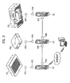
- FIGS. 2 and 3 illustrate air conditioning systems in accordance with a first preferred embodiment of the present invention.
- the air conditioning system includes at least one room cooling/heating unit 110, a ventilating unit 120, an air purifying unit 130, and a controller for controlling the units.
- the controller is able to communicate with the room cooling/heating unit, the ventilating unit, and the air purifying unit, such that the units are operated interlocked with one another.
- the controller For an interlocked operation of the units, the controller includes temperature sensors (not shown), and a microcomputer (not shown).
- the temperature sensor measures a room temperature
- the microcomputer produces control data for controlling operation of the units. If the temperature measured at the temperature sensor is outside of a range preset at the microcomputer, the controller puts the room cooling/heating unit 110 into operation.
- the controller includes a timer for measuring an operation time period of the room cooling/heating unit 110.
- the controller puts the ventilating unit 120 into operation. Then, outdoor air is introduced into the room by the ventilating unit 120. At this time, it is preferable that the air purifying unit 130 is operated at the same time for purifying air introduced into the room.
- the room cooling/heating unit Since the outdoor air having an outdoor temperature is introduced into the room during the ventilation, the room is in an unstable state in which the room temperature varies. In this instance, it is difficult for the room cooling/heating unit to determine which one of the cooling and heating is to be performed. Therefore, it is preferable that the room cooling/heating unit is not operated during the ventilation.
- the controller puts the ventilating unit 120 and the air purifying unit 130 into operation, and operation of the room cooling/heating unit 110 is stopped. According to this, an energy consumption efficiency of the air conditioning system can be improved.
- the controller in accordance with the embodiment of the present invention includes a room cooling/heating controller 111, a ventilating controller 121, and an air purifying controller 131.
- the room cooling/heating controller 111 is able to communicate with the room cooling/heating unit 110, for controlling the room cooling/heating unit 110.
- the ventilating controller 121 is able to communicate with the ventilating unit 120, for controlling the ventilating unit 120, and is able to exchange data with the room cooling/heating controller 111, for making an interlocked operation of the room cooling/heating unit 110, and the ventilating unit 120.
- the air purifying controller 131 is able to communicate with the air purifying unit 130, for controlling the air purifying unit, and is able to exchange data with the ventilating controller 121, for making an interlocked operation of above units.
- the room cooling/heating unit 110 is an indoor unit of an air conditioner.
- the air conditioner includes an outdoor unit and an indoor unit, for making heat exchange between refrigerant flowing in the units, and air, to cool or heat the air selectively.
- the rooms are provided with the indoor units, respectively.
- the room cooling/heating units may be controlled collectively by one room cooling/heating controller.
- data transceiver parts 401, and 402 are provided to the room cooling/heating unit 110 and the room cooling/heating controller 111 respectively, for data transmission/reception therebetween.
- the data transceiver part 402 in the room cooling /heating controller 111 receives data from the data transceiver part 401 in the room cooling /heating unit 110.
- the ventilating unit 120 ventilates the room, selectively.
- the ventilating unit 120 includes a duct making the room and outdoor in communication, and a fan provided inside of the duct.
- the duct is in communication with the rooms, and provided with fans as many as a number determined taking a total capacity of rooms into account.
- the ventilating controller 121 is able to communicate with the ventilating unit 120, for remote control of the ventilating unit 120.
- the ventilating controller 121 and the ventilating unit 120 exchange data through data transceiver parts 403, and 404, respectively.
- Data exchange between the ventilating controller 121 and the room cooling /heating controller 111 is made through data transceiver parts 406, and 405. According to this, the room cooling/heating and ventilation by above units are operated interlocked with each other.
- the air purifying unit 130 purifies contaminated room air.
- the air purifying unit 130 draws room air, removes odor and dust from the room air, and discharges to the room, again.
- the air purifying controller 131 is connected so as to be able to communicate with the air purifying unit 130, for controlling the air purifying unit 130. That is, the air purifying controller 131 and the air purifying unit 130 are connected such that data is exchanged through data transceiver parts 407, and 408.
- the air purifying controller 131 and the ventilating controller 121 are provided with data transceiver parts 410, and 409, additionally.
- the ventilating controller 121 and the air purifying controller 131 are connected such that communication can be made through the transceiver parts 410, and 409. According to this, the air purifying unit 130 and the ventilating unit 120 are operated interlocked with each other.
- the ventilating unit 120 is operated in response to a control data from the ventilating controller 121.
- the ventilating controller 121 since the ventilating controller 121 -provides a control data to the air purifying controller 131, the air purifying unit 130 can be operated interlocked with operation of the room cooling/heating unit 110 and the ventilating unit 120. According to this, the units 110, 120, and 130 are operated according to operation of other units.
- the air purifying controller 131 is connected to the room cooling/heating controller 111 so as to be able to transmit/receive data, and the air purifying unit 130 and the room cooling/heating unit 110 can be operated interlocked with each other.
- one of the room cooling/heating unit 111, the ventilating controller 121, and the air purifying controller 131 controls a corresponding unit, remotely. That is, it is preferable that at least any one of the controllers is a remote controller.
- FIG. 3 illustrates a diagram showing the controllers controlled by apparatus connected to the Internet.
- At least one of the room cooling /heating controller 111, the ventilating controller 120, and the air purifying controller 130 is controlled with a computer connected to the Internet. That is, one of the controllers is provided to be able to communicate with the computer connected to the Internet, so that the user can control operation of the air conditioning system with the computer, on an outside of the building far from the building. Moreover, error signals from the controllers 111, 121, and 131 can be known through the computer connected to the Internet. Moreover, since the control through the Internet can be carried out by an automated program, the units can be managed without attendance of a man.
- the room cooling/heating controller 111 puts the room cooling/heating unit 110 into operation. In this instance, the room cooling/heating controller 111 puts the room cooling/heating unit 110 into operation, or stops operation thereof repeatedly according to the room temperature, to maintain the room temperature at an appropriate temperature.
- the room cooling/heating controller 111 or the room cooling/heating unit 110 is provided with a temperature sensor for measuring the room temperature and a microcomputer at one side thereof. If the temperature measured at the temperature sensor is outside of a range preset at the computer, the microcomputer issues an order for the room cooling/heating unit 110 to start operation. Then, the room cooling/heating unit 110 cools or heats the room for a preset time period.
- a control data performed through the room cooling/heating controller 111 is transmitted from the data transceiver part 405 of the room cooling/heating controller 111 to the data transceiver part 406 of the ventilating controller 121.
- the air conditioning system has the room ventilated after the room cooling/heating unit 110 is operated for a preset time period.
- the room cooling/heating controller 111 or the room cooling/heating unit 110 is provided with a timer therein for measuring a time period starting from starting of operation of the room cooling/heating unit 110.
- a control data is provided from the room cooling/heating controller 111 to the ventilating controller 121.
- the ventilating controller 121 Upon receiving the signal, the ventilating controller 121 puts the ventilating unit 120 into operation. That is, an operation staring point of the ventilating unit 120 is dependent on the operation time period of the room cooling/heating unit 110. During the ventilating unit 120 is operated, the room temperature is unstable due to introduction of the outdoor air into the room. Therefore, when ventilation of the room is required, it is preferable that operation of the room cooling/heating unit is stopped, and the ventilating unit 120 is put into operation. By doing so, the energy consumption efficiency of the air conditioning system can be improved.
- the air purifying controller 131 puts the air purifying unit 130 into operation. That is, a control data informing that the ventilating unit 120 is started is provided from the ventilating controller 121 to the air purifying controller 131, the air purifying controller 131 puts the air purifying unit 130 into operation.
- the air purifying controller 131 puts the air purifying unit 130 into operation at the same time with the operation of the ventilating unit 120. Then, the air purifying unit 130 removes dust and odor from the outdoor air introduced into the room.
- the air purifying unit 130 is operated at the same time with the ventilating unit 120, not necessarily. That is, if room air is contaminated heavily, only the air purifying unit may be operated.
- the units After the ventilating and air purifying are performed for the preset time period, the units are stopped. Then, a control data informing that the units are stopped is provided to the room cooling/heating controller 111, and the controller puts the room cooling/heating unit 110 into operation selectively depending on the room temperature.
- FIG. 4 illustrates a diagram of an air conditioning system in accordance with a second preferred embodiment of the present invention.
- the air conditioning system in the air conditioning system, units, particularly, the room cooling/heating units 110 are grouped, and the grouped units are controlled by one controller. Therefore, the air conditioning system is provided with a ventilating and air purifying controller 221 having a combined function of the ventilating controller and the air purifying controller.
- the room cooling/heating controller 211 is connected to the plurality of room cooling/heating units 110 so as to be able to communicate. At least one room cooling/heating unit is provided to each of the rooms, all of which are controlled by one room cooling/heating unit.
- the room cooling/heating units 110 may be connected to the room cooling/heating controllers so as to be able to communicate respectively, and the room cooling/heating controllers can be controlled by a separate unitized room cooling/heating remote controller.
- the room cooling/heating units 110 and the room cooling/heating controller 211 have data transceiver parts 411, and 412 respectively for transmission/reception of data therebetween.
- the data transceiver part 412 in the room cooling/heating controller 211 receives data from the data transceiver parts 411 of the room cooling/heating units 110, collectively.
- the ventilating unit 130 and the air purifying unit 120 are connected with data transceiver parts 423, and 414 so as to be able to communicate to each other, and the units are interlocked. Therefore, when the ventilating unit 120 is started, a control data is provided to the air purifying unit 130 connected to the ventilating unit 120, and by the control data provided thereto, the air purifying unit 130 is also operated.
- the ventilating and air purifying controller 221 is connected such that it can communicate with one of the ventilating unit 120 and the air purifying unit 130. Therefore, the ventilating unit 120 and the air purifying unit 130 are interlocked. In this instance, it is preferable that the ventilating and air purifying controller 221 is connected to the air purifying unit 130 so as to be able to communicate with each other. This is because there are cases occurred frequently, in which operation of only the air purifying unit 130 is required.
- control data is provided from the ventilating and air purifying controller 221 to the air purifying unit 130 directly, a response speed of the air purifying unit 130 with respect to the control data is improved.
- the ventilating and air purifying controller 221 and the air purifying unit 130 are provided with separate data transceiver parts 415, and 416 respectively for transmission/reception of data therebetween.
- the ventilating and air purifying controller 221 may be connected both to the ventilating unit 120 and the air purifying unit 130 so as to be able to communicate with each other.
- the ventilating and air purifying controller 221 and the room cooling/heating unit 211 are provided with separate data transceiver parts 418, and 417 respectively for data transmission/reception of data therebetween.
- the room cooling/heating controller 211 or the ventilating and air purifying controller 221 controls the room cooling/heating unit 110, the ventilating unit 120, and the air purifying unit 130, remotely.
- the at least one of the room cooling/heating controller 211 and the ventilating and air purifying controller 221 is controllable from a distant place through the Internet.
- the control though the Internet can be embodied according to a method the same with the first embodiment.
- the room cooling/heating controller 211 is provided with a temperature sensor for measuring a room temperature.
- a control data is provided to the data transceiver part 418 in the ventilating and air purifying controller 221 through the data transceiver part 417 in the room cooling/heating controller 211.
- the ventilating and air purifying controller 221 knows starting and stopping time points of the room cooling/heating unit 110, and calculates or sets starting times of the ventilating unit 120, and the air purifying unit 130.
- the room cooling/heating controller 211 stops operation of the room cooling/heating unit 110. Also, the ventilating and air purifying controller 221 puts both the ventilating unit 120 and the air purifying unit 130 into operation, to remove dust and odor from the outdoor air introduced into the room.
- a control data is provided to the ventilating unit 130 through the air purifying unit 120.
- the ventilating and air purifying controller 221 stops the ventilating unit 120 and the air purifying unit 130.
- the control data is provided to the room cooling/heating controller 211, to put the room cooling/heating unit again according to the room temperature.
- the ventilating unit 120 and the air purifying unit 130 in accordance with the second preferred embodiment of the present invention are operated after the room cooling/heating unit 110 is operated for a predetermined time period. That is, it is preferable that starting time control of the ventilating unit and the air purifying unit is performed identical to the first embodiment.
- FIG. 6 illustrates a diagram of an air conditioning system in accordance with a third preferred embodiment of the present invention.
- the room cooling/heating unit 110, the ventilating unit 120, and the air purifying unit 130 are controlled by single unitized controller 300.
- the unitized controller 300 has a display screen for displaying individual operation states of above units. According to this, after knowing operation states of the units through the display screen, the controller 300 is operated, to control the units 110, 120, and 130, collectively.
- the unitized controller 300 can be connected to one of the room cooling/heating unit 110, the ventilating unit 120, and the air purifying unit 130 so as to be able to communicate with each other.
- data transceiver parts 419, 420, 421, and 422 are provided thereto respectively, for transmission/reception of control data.
- the unitized controller 300 may be connected to the room cooling/heating unit 110.
- the ventilating unit 120, and the air purifying unit 130 are connected to the room cooling/heating unit 110 through the data transceiver parts 419, 421, 420, and 422.
- FIGS. 7A and 7B illustrate a diagram of changed connection between the unitized controller 300 and the units.
- the air purifying unit 130 is provided with two data transceiver parts 425, and 426 for data transmission/reception to/from the room cooling/heating unit 110 and the ventilating unit 120, and the room cooling/heating unit 110 and the ventilating unit 120 are respectively provided with data transceiver parts for data transmission/reception to/from the air purifying unit 130.
- a control data is transmitted to the ventilating unit 120 from the unitized controller 300 through the room cooling/heating unit 110 and the ventilating unit 120.
- the ventilating unit 120 is provided with two data transceiver parts 429, and 430 for data transmission/reception to/from the room cooling/heating unit 110 and the ventilating unit 120, and the room cooling/heating unit 110 and the air purifying unit 130 may only be provided with data transceiver parts 431, and 432 for data transmission/reception to/from the ventilating unit 120, respectively.
- the room cooling/heating unit 110 is further provided with a separate data transceiver part 423 for communication with the unitized controller 300, and the unitized controller 300 is also provided with a separate data transceiver part 424.
- the unitized controller 300 controls the room cooling/heating unit, remotely. Moreover, as shown in FIG. 8, alike the first embodiment, the unitized controller 300 can be operated from a distant place by using a computer connected to the Internet.
- the unitized controller 300 controls the room cooling/heating unit 110. After the room cooling/heating process is progressed for a preset time period, the unitized controller 300 stops operation of the room cooling/heating unit 110, and puts the ventilating unit 120 and the air purifying unit 130 into operation at the same time.
- the unitized controller 300 includes a temperature sensor for measuring a room temperature, and a timer for measuring an operation time period of the room cooling/heating unit.
- the unitized controller 300 includes a microcomputer for generating the control data based on data measured at the temperature sensor and the timer.
- the data for controlling the ventilating unit 120, and the air purifying unit 130 is provided to the data transceiver part 419 of the ventilating unit 120 and the data transceiver part 420 of the air purifying unit 130 from the unitized controller 300 through the data transceivers 421, and 422 of the room cooling/heating unit 110.
- the ventilating unit 120 ventilates the room, and the air purifying unit 130 filters dust and odor from outdoor air introduced in the room.
- the unitized controller 300 Upon completion of the ventilation and air purification, the unitized controller 300 stops operation of the ventilating unit 120 and the air purifying unit 130, and puts the room cooling/heating unit 110 into operation again depending on the room temperature.
- operation of the ventilating unit 120 and the air purifying unit 130 are controlled according to the operation time period of the room cooling/heating unit 110, and the units are operated interlocked with one another, energy consumption efficiency of the air conditioning system can be improved.
- the air conditioning system of the present invention has the following advantages.
- the interlocked operation of the units in the air conditioning system permits to improve energy consumption efficiency of the air conditioning system.
- the air conditioning system includes the air purifying unit operated interlocked with the room cooling/heating unit and the ventilating unit, the air conditioning system of the present invention can perform more various functions than the related art.
- the invention provides an air conditioning system including at least one room cooling/heating unit for cooling/heating a room selectively, at least one ventilating unit for ventilating a room selectively, at least one air purifying unit for purifying contaminated room air selectively, and a controller provided so as to be able to communicate with the room cooling/heating unit, the ventilating unit, and the air purifying unit, for controlling above units interlocked with one another, thereby providing an air conditioning system in which a room cooling/heating function, a ventilating function, and an air purifying system are controlled, collectively.
Abstract
Description
Claims (18)
- An air conditioning system comprising:at least one room cooling/heating unit (110) for cooling/heating a room selectively;at least one ventilating unit (120) for ventilating a room selectively;at least one air purifying unit (130) for purifying contaminated room air selectively; anda controller provided so as to be able to communicate with the room cooling/heating unit (110), the ventilating unit (120), and the air purifying unit (130), for controlling above units interlocked with one another.
- An air conditioning system comprising:at least one room cooling/heating unit (110) for cooling/heating a room selectively;at least one ventilating unit (120) for ventilating a room selectively;at least one air purifying unit (130) for purifying contaminated room air selectively; anda unitized controller (300) connected to one of the room cooling/heating unit (110), the ventilating unit (120), and the air purifying unit (130) so as to be able to communicate therewith, for making the room cooling/heating unit (110), the ventilating unit (120), and the air purifying unit (130) to operate interlocked with one another.
- The air conditioning system as claimed in claim 2, wherein the room cooling/heating unit (110), the ventilating unit (120), and the air purifying unit (130) are connected so as to be able to transmit/receive data to/from one another.
- The air conditioning system as claimed in claim 1, wherein the controller includes;a room cooling/heating controller (111) connected to the room cooling/heating unit (110) so as to be able to communicate therewith for controlling the room cooling/heating unit (110),a ventilating controller (121) connected to the ventilating unit (120) so as to be able to communicate therewith, for controlling the ventilating unit (120), and making the room cooling/heating unit (110) and the ventilating unit (120) to operate interlocked with each other by data transmission/reception to/from the room cooling/heating unit (110), andan air purifying controller (131) connected to the air purifying unit (130) so as to be able to communicate therewith for controlling the air purifying unit (130), and making the units to operate interlocked with each other by data transmission/reception to/from the ventilating unit (120).
- The air conditioning system as claimed in claim 1, wherein the controller includes;a room cooling/heating controller (211) connected to the room cooling/heating unit (110) so as to be able to communicate therewith, for remote control of the room cooling/heating unit (110), anda ventilating and air purifying controller (221) connected to the ventilating unit (120) and the air purifying unit (130) so as to be able to communicate therewith for controlling the ventilating unit (120) and the air purifying unit (130) remotely, and making the room cooling/heating units (110) to operate interlocked with one another by transmission/reception of data to/from the room cooling/heating controller (111).
- The air conditioning system as claimed in claim 1, wherein the controller includes a unitized controller (300) connected to the room cooling/heating unit (110), the ventilating unit (120), and the air purifying unit (130) so as to be able to communicate therewith for controlling the units remotely, and making the units to operate interlocked with one another.
- The air conditioning system as claimed in one of claims 1 to 6, wherein the controller includes;a temperature sensor for measuring a room temperature, anda microcomputer for generating a control signal for controlling operation of the units.
- The air conditioning system as claimed in one of claims 1 to 6, wherein the controller puts the room cooling/heating unit (110) into operation, if the temperature measured at the temperature sensor is outside of a range preset at the microcomputer.
- The air conditioning system as claimed in one of claims 1 to 8, wherein the controller further includes a timer for measuring an operation time period of the room cooling/heating unit (110).
- The air conditioning system as claimed in claim 9, wherein the controller stops operation of the room cooling/heating unit (110) if the operation time period measured at the timer reaches to a time period preset at the microcomputer.
- The air conditioning system as claimed in one of claims 9 to 10, wherein the controller puts the ventilating unit (120) into operation if the operation time period measured at the timer reaches to a time period preset at the microcomputer.
- The air conditioning system as claimed in claim 11, wherein the controller puts the air purifying unit (130) into operation at the same time with putting the ventilating unit (120) into operation.
- The air conditioning system as claimed in one of claims 1 to 12, wherein a plurality of room cooling/heating units (110) are provided so as to be able to communicate with the controller.
- The air conditioning system as claimed in one of claims 1 to 13, wherein the controller controls the units, remotely.
- The air conditioning system as claimed in one of claims 1 to 14, wherein the controller is controlled from a distant place by using a computer connected to the Internet.
- A method for controlling an air conditioning system comprising:at least one room cooling/heating unit (110) for cooling/heating a room selectively;at least one ventilating unit (120) for ventilating a room selectively;at least one air purifying unit (130) for purifying contaminated room air selectively; anda controller (300) provided so as to be able to communicate with the room cooling/heating unit (110), the ventilating unit (120), and the air purifying unit (130), for controlling above units interlocked with one another, the method comprising:a first step for measuring a room temperature;a second step for the controller to put the room cooling/heating unit (110) into operation if the measured temperature is outside of a preset range; anda third step for the controller to put the ventilating unit (120) into operation if an operation time period of the room cooling/heating unit reaches to a preset time period.
- The method as claimed in claim 16, wherein the third step includes the step of putting the air purifying unit (130) into operation at the same time with the ventilating unit (120).
- The method as claimed in one of claims 16 to 17, wherein the third step includes the step of stopping operation of the room cooling/heating unit (110).
Applications Claiming Priority (2)
| Application Number | Priority Date | Filing Date | Title |
|---|---|---|---|
| KR2004047648 | 2004-06-24 | ||
| KR1020040047648A KR100546618B1 (en) | 2004-06-24 | 2004-06-24 | air conditioning system |
Publications (2)
| Publication Number | Publication Date |
|---|---|
| EP1610069A1 true EP1610069A1 (en) | 2005-12-28 |
| EP1610069B1 EP1610069B1 (en) | 2007-10-10 |
Family
ID=34934771
Family Applications (1)
| Application Number | Title | Priority Date | Filing Date |
|---|---|---|---|
| EP05007408A Expired - Fee Related EP1610069B1 (en) | 2004-06-24 | 2005-04-05 | Air conditioning system and method for controlling the same |
Country Status (5)
| Country | Link |
|---|---|
| US (1) | US20050284161A1 (en) |
| EP (1) | EP1610069B1 (en) |
| KR (1) | KR100546618B1 (en) |
| CN (1) | CN100346111C (en) |
| ES (1) | ES2295997T3 (en) |
Cited By (2)
| Publication number | Priority date | Publication date | Assignee | Title |
|---|---|---|---|---|
| WO2007097513A3 (en) * | 2006-02-20 | 2009-05-22 | Lg Electronics Inc | Air conditioning system and control method thereof |
| EP2053318A3 (en) * | 2007-10-24 | 2011-02-23 | LG Electronics Inc. | Air conditioning system |
Families Citing this family (9)
| Publication number | Priority date | Publication date | Assignee | Title |
|---|---|---|---|---|
| KR100884644B1 (en) * | 2007-01-29 | 2009-02-23 | 웅진코웨이주식회사 | Air cleaner capable of interworked driving |
| US8290628B2 (en) * | 2010-07-23 | 2012-10-16 | Lg Electronics Inc. | Air conditioner and method for controlling the same |
| CN104930613A (en) * | 2015-06-19 | 2015-09-23 | 河北中康韦尔环境科技有限公司 | Hospital-pathology-department air quality detecting and purifying system |
| CN105240991B (en) * | 2015-09-09 | 2018-02-27 | 周东伟 | Intelligent indoor air cleaning system and its air purification method |
| CN106123246A (en) * | 2016-08-11 | 2016-11-16 | 合肥通用电源设备有限公司 | A kind of integrated power supply switching control system |
| CN106985863B (en) * | 2016-12-27 | 2019-01-04 | 石家庄国祥运输设备有限公司 | The method of high visitor's motor-car air-conditioner set auto-control |
| US11235643B2 (en) * | 2018-11-27 | 2022-02-01 | Scott Bradley Baker | Air vent assembly and control system |
| US20220373197A1 (en) | 2021-05-24 | 2022-11-24 | Lg Electronics Inc. | Air-conditioning system |
| US20220373204A1 (en) | 2021-05-24 | 2022-11-24 | Lg Electronics Inc. | Air-conditioning system |
Citations (5)
| Publication number | Priority date | Publication date | Assignee | Title |
|---|---|---|---|---|
| US5042997A (en) * | 1990-07-27 | 1991-08-27 | Rhodes James A | Air control system providing healthful enclosed environment |
| JPH07217956A (en) * | 1994-01-24 | 1995-08-18 | Sanreiki:Kk | Air ventilation control device |
| JP2000111128A (en) * | 1998-10-08 | 2000-04-18 | Sanyo Electric Co Ltd | Air conditioner |
| EP1182407A2 (en) * | 2000-08-19 | 2002-02-27 | Lampe & Martens Gebäudetechnik Gmbh & Co. KG | Device for controling and/or monitoring the climatic conditions inside a building |
| US6717513B1 (en) * | 1999-01-09 | 2004-04-06 | Heat-Timer Corporation | Electronic message delivery system utilizable in the monitoring of remote equipment and method of same |
Family Cites Families (8)
| Publication number | Priority date | Publication date | Assignee | Title |
|---|---|---|---|---|
| CN2161857Y (en) * | 1993-08-25 | 1994-04-13 | 王晓明 | Air conditioner |
| JP3404150B2 (en) * | 1994-09-28 | 2003-05-06 | 東芝キヤリア株式会社 | Air conditioner and control method thereof |
| US5538471A (en) * | 1994-11-15 | 1996-07-23 | Innovative Air Systems, Inc. | Dynamic particulate control system and method of operation |
| US5810657A (en) * | 1994-11-22 | 1998-09-22 | Lighthouse Associates, Inc. | Controller to maintain a certain set of environmental parameters in an environment |
| KR19990042958A (en) * | 1997-11-28 | 1999-06-15 | 윤종용 | Operation controller and method of air conditioner |
| US6406367B1 (en) * | 2000-12-26 | 2002-06-18 | Carrier Corporation | Indoor air quality control |
| AU2002305270A1 (en) * | 2001-04-30 | 2002-11-11 | Emerson Retail Services Inc. | Building system performance analysis |
| US7083109B2 (en) * | 2003-08-18 | 2006-08-01 | Honeywell International Inc. | Thermostat having modulated and non-modulated provisions |
-
2004
- 2004-06-24 KR KR1020040047648A patent/KR100546618B1/en not_active IP Right Cessation
-
2005
- 2005-04-05 US US11/098,478 patent/US20050284161A1/en not_active Abandoned
- 2005-04-05 ES ES05007408T patent/ES2295997T3/en active Active
- 2005-04-05 EP EP05007408A patent/EP1610069B1/en not_active Expired - Fee Related
- 2005-04-14 CN CNB2005100652400A patent/CN100346111C/en not_active Expired - Fee Related
Patent Citations (5)
| Publication number | Priority date | Publication date | Assignee | Title |
|---|---|---|---|---|
| US5042997A (en) * | 1990-07-27 | 1991-08-27 | Rhodes James A | Air control system providing healthful enclosed environment |
| JPH07217956A (en) * | 1994-01-24 | 1995-08-18 | Sanreiki:Kk | Air ventilation control device |
| JP2000111128A (en) * | 1998-10-08 | 2000-04-18 | Sanyo Electric Co Ltd | Air conditioner |
| US6717513B1 (en) * | 1999-01-09 | 2004-04-06 | Heat-Timer Corporation | Electronic message delivery system utilizable in the monitoring of remote equipment and method of same |
| EP1182407A2 (en) * | 2000-08-19 | 2002-02-27 | Lampe & Martens Gebäudetechnik Gmbh & Co. KG | Device for controling and/or monitoring the climatic conditions inside a building |
Non-Patent Citations (2)
| Title |
|---|
| PATENT ABSTRACTS OF JAPAN vol. 1995, no. 11 26 December 1995 (1995-12-26) * |
| PATENT ABSTRACTS OF JAPAN vol. 2000, no. 07 29 September 2000 (2000-09-29) * |
Cited By (4)
| Publication number | Priority date | Publication date | Assignee | Title |
|---|---|---|---|---|
| WO2007097513A3 (en) * | 2006-02-20 | 2009-05-22 | Lg Electronics Inc | Air conditioning system and control method thereof |
| CN101631994A (en) * | 2006-02-20 | 2010-01-20 | Lg电子株式会社 | Air conditioning system and control method thereof |
| CN101631994B (en) * | 2006-02-20 | 2012-09-26 | Lg电子株式会社 | Air conditioning system and control method thereof |
| EP2053318A3 (en) * | 2007-10-24 | 2011-02-23 | LG Electronics Inc. | Air conditioning system |
Also Published As
| Publication number | Publication date |
|---|---|
| KR100546618B1 (en) | 2006-01-26 |
| ES2295997T3 (en) | 2008-04-16 |
| EP1610069B1 (en) | 2007-10-10 |
| US20050284161A1 (en) | 2005-12-29 |
| CN100346111C (en) | 2007-10-31 |
| KR20050122523A (en) | 2005-12-29 |
| CN1712841A (en) | 2005-12-28 |
Similar Documents
| Publication | Publication Date | Title |
|---|---|---|
| EP1610069B1 (en) | Air conditioning system and method for controlling the same | |
| US10635119B2 (en) | Method and system for configuring wireless sensors in an HVAC system | |
| EP1698833B1 (en) | Multi-air conditioner central control system | |
| US7590469B2 (en) | Method and apparatus for configuring a communicating environmental conditioning network | |
| US20140041846A1 (en) | Hvac system with multiple equipment interface modules | |
| AU2016392133B2 (en) | Air-conditioning control system and remote control device | |
| US20150308707A1 (en) | Air-conditioning system | |
| JP2006308280A (en) | Air conditioning system and its control method | |
| JP2008232531A (en) | Remote performance monitoring device and method | |
| JP6948812B2 (en) | Management equipment, air conditioning systems, management methods, and programs | |
| JP5136403B2 (en) | Equipment control system | |
| KR101936634B1 (en) | Management system | |
| EP3663661A1 (en) | Hvac controller with a zone commissioning mode | |
| JP4698292B2 (en) | Air conditioning apparatus and control method thereof | |
| CN107431734B (en) | Indoor device, communication adapter, control method, and recording medium | |
| JP2021076287A (en) | Air conditioner | |
| KR20110004154A (en) | Remote controller for control building unit | |
| US11940166B2 (en) | Air conditioning system for transferring air in an air-conditioned room | |
| CN109764500A (en) | For solving control method, device and the unit of unit operational mode conflict | |
| KR102560125B1 (en) | Plug-in control system for integrating equipment | |
| KR101198182B1 (en) | Schedule backup device for air conditioner | |
| JP2009204194A (en) | Indoor unit of air conditioner for facility | |
| KR20170137998A (en) | A system for air-cleaning | |
| JP2002039604A (en) | Equipment control system | |
| JP2014066504A (en) | Air conditioner management device |
Legal Events
| Date | Code | Title | Description |
|---|---|---|---|
| PUAI | Public reference made under article 153(3) epc to a published international application that has entered the european phase |
Free format text: ORIGINAL CODE: 0009012 |
|
| 17P | Request for examination filed |
Effective date: 20050405 |
|
| AK | Designated contracting states |
Kind code of ref document: A1 Designated state(s): AT BE BG CH CY CZ DE DK EE ES FI FR GB GR HU IE IS IT LI LT LU MC NL PL PT RO SE SI SK TR |
|
| AX | Request for extension of the european patent |
Extension state: AL BA HR LV MK YU |
|
| AKX | Designation fees paid |
Designated state(s): ES FR GB |
|
| REG | Reference to a national code |
Ref country code: DE Ref legal event code: 8566 |
|
| GRAP | Despatch of communication of intention to grant a patent |
Free format text: ORIGINAL CODE: EPIDOSNIGR1 |
|
| GRAS | Grant fee paid |
Free format text: ORIGINAL CODE: EPIDOSNIGR3 |
|
| GRAA | (expected) grant |
Free format text: ORIGINAL CODE: 0009210 |
|
| AK | Designated contracting states |
Kind code of ref document: B1 Designated state(s): ES FR GB |
|
| REG | Reference to a national code |
Ref country code: GB Ref legal event code: FG4D |
|
| REG | Reference to a national code |
Ref country code: ES Ref legal event code: FG2A Ref document number: 2295997 Country of ref document: ES Kind code of ref document: T3 |
|
| ET | Fr: translation filed | ||
| PGFP | Annual fee paid to national office [announced via postgrant information from national office to epo] |
Ref country code: FR Payment date: 20080312 Year of fee payment: 4 Ref country code: ES Payment date: 20080520 Year of fee payment: 4 |
|
| PLBE | No opposition filed within time limit |
Free format text: ORIGINAL CODE: 0009261 |
|
| STAA | Information on the status of an ep patent application or granted ep patent |
Free format text: STATUS: NO OPPOSITION FILED WITHIN TIME LIMIT |
|
| 26N | No opposition filed |
Effective date: 20080711 |
|
| GBPC | Gb: european patent ceased through non-payment of renewal fee |
Effective date: 20090405 |
|
| REG | Reference to a national code |
Ref country code: FR Ref legal event code: ST Effective date: 20091231 |
|
| PG25 | Lapsed in a contracting state [announced via postgrant information from national office to epo] |
Ref country code: GB Free format text: LAPSE BECAUSE OF NON-PAYMENT OF DUE FEES Effective date: 20090405 Ref country code: FR Free format text: LAPSE BECAUSE OF NON-PAYMENT OF DUE FEES Effective date: 20091222 |
|
| REG | Reference to a national code |
Ref country code: ES Ref legal event code: FD2A Effective date: 20090406 |
|
| PG25 | Lapsed in a contracting state [announced via postgrant information from national office to epo] |
Ref country code: ES Free format text: LAPSE BECAUSE OF NON-PAYMENT OF DUE FEES Effective date: 20090406 |