EP1614465A1 - Microfluidic system for chemical analysis - Google Patents
Microfluidic system for chemical analysis Download PDFInfo
- Publication number
- EP1614465A1 EP1614465A1 EP05076524A EP05076524A EP1614465A1 EP 1614465 A1 EP1614465 A1 EP 1614465A1 EP 05076524 A EP05076524 A EP 05076524A EP 05076524 A EP05076524 A EP 05076524A EP 1614465 A1 EP1614465 A1 EP 1614465A1
- Authority
- EP
- European Patent Office
- Prior art keywords
- fluid
- substrate
- fluid sample
- reagent
- inlet
- Prior art date
- Legal status (The legal status is an assumption and is not a legal conclusion. Google has not performed a legal analysis and makes no representation as to the accuracy of the status listed.)
- Granted
Links
- 238000004458 analytical method Methods 0.000 title claims abstract description 58
- 239000000126 substance Substances 0.000 title description 16
- 239000012530 fluid Substances 0.000 claims abstract description 158
- 239000000758 substrate Substances 0.000 claims abstract description 73
- 239000003153 chemical reaction reagent Substances 0.000 claims abstract description 58
- 238000002156 mixing Methods 0.000 claims abstract description 18
- 238000004891 communication Methods 0.000 claims abstract description 10
- 230000003287 optical effect Effects 0.000 claims description 23
- 238000000034 method Methods 0.000 claims description 18
- 238000005070 sampling Methods 0.000 claims description 14
- 238000005259 measurement Methods 0.000 claims description 12
- OKTJSMMVPCPJKN-UHFFFAOYSA-N Carbon Chemical compound [C] OKTJSMMVPCPJKN-UHFFFAOYSA-N 0.000 claims description 8
- 238000012544 monitoring process Methods 0.000 claims description 7
- 238000012545 processing Methods 0.000 claims description 7
- 239000013307 optical fiber Substances 0.000 claims description 5
- 239000004033 plastic Substances 0.000 claims description 5
- 239000002244 precipitate Substances 0.000 claims description 5
- 229920000089 Cyclic olefin copolymer Polymers 0.000 claims description 4
- 239000004713 Cyclic olefin copolymer Substances 0.000 claims description 4
- 239000003673 groundwater Substances 0.000 claims description 4
- 230000005540 biological transmission Effects 0.000 claims description 3
- 239000003014 ion exchange membrane Substances 0.000 claims description 3
- 239000000463 material Substances 0.000 claims description 2
- 238000001053 micromoulding Methods 0.000 claims description 2
- 238000003860 storage Methods 0.000 claims description 2
- 238000007599 discharging Methods 0.000 claims 2
- 238000012512 characterization method Methods 0.000 claims 1
- 239000000523 sample Substances 0.000 description 39
- XLYOFNOQVPJJNP-UHFFFAOYSA-N water Substances O XLYOFNOQVPJJNP-UHFFFAOYSA-N 0.000 description 12
- 230000015572 biosynthetic process Effects 0.000 description 11
- 238000007726 management method Methods 0.000 description 6
- 238000010586 diagram Methods 0.000 description 5
- 239000002699 waste material Substances 0.000 description 5
- 150000002500 ions Chemical class 0.000 description 4
- UHOVQNZJYSORNB-UHFFFAOYSA-N Benzene Chemical compound C1=CC=CC=C1 UHOVQNZJYSORNB-UHFFFAOYSA-N 0.000 description 3
- CURLTUGMZLYLDI-UHFFFAOYSA-N Carbon dioxide Chemical compound O=C=O CURLTUGMZLYLDI-UHFFFAOYSA-N 0.000 description 3
- 238000001514 detection method Methods 0.000 description 3
- 238000004401 flow injection analysis Methods 0.000 description 3
- 239000003292 glue Substances 0.000 description 3
- 239000007788 liquid Substances 0.000 description 3
- 239000000047 product Substances 0.000 description 3
- RWSOTUBLDIXVET-UHFFFAOYSA-N Dihydrogen sulfide Chemical compound S RWSOTUBLDIXVET-UHFFFAOYSA-N 0.000 description 2
- 229910002651 NO3 Inorganic materials 0.000 description 2
- NHNBFGGVMKEFGY-UHFFFAOYSA-N Nitrate Chemical compound [O-][N+]([O-])=O NHNBFGGVMKEFGY-UHFFFAOYSA-N 0.000 description 2
- 238000013494 PH determination Methods 0.000 description 2
- 239000000853 adhesive Substances 0.000 description 2
- 230000001070 adhesive effect Effects 0.000 description 2
- 229910052788 barium Inorganic materials 0.000 description 2
- 229910002092 carbon dioxide Inorganic materials 0.000 description 2
- 230000001419 dependent effect Effects 0.000 description 2
- 238000013461 design Methods 0.000 description 2
- 239000000835 fiber Substances 0.000 description 2
- 239000007789 gas Substances 0.000 description 2
- 229910001385 heavy metal Inorganic materials 0.000 description 2
- 229910000037 hydrogen sulfide Inorganic materials 0.000 description 2
- 238000002347 injection Methods 0.000 description 2
- 239000007924 injection Substances 0.000 description 2
- 238000011545 laboratory measurement Methods 0.000 description 2
- 229910052751 metal Inorganic materials 0.000 description 2
- 239000002184 metal Substances 0.000 description 2
- 239000000203 mixture Substances 0.000 description 2
- 238000001139 pH measurement Methods 0.000 description 2
- -1 poly(dimethylsiloxane) Polymers 0.000 description 2
- 229920000435 poly(dimethylsiloxane) Polymers 0.000 description 2
- 239000010453 quartz Substances 0.000 description 2
- 230000035484 reaction time Effects 0.000 description 2
- 150000003839 salts Chemical class 0.000 description 2
- 239000010703 silicon Substances 0.000 description 2
- 229910052710 silicon Inorganic materials 0.000 description 2
- VYPSYNLAJGMNEJ-UHFFFAOYSA-N silicon dioxide Inorganic materials O=[Si]=O VYPSYNLAJGMNEJ-UHFFFAOYSA-N 0.000 description 2
- 238000012360 testing method Methods 0.000 description 2
- 229910006130 SO4 Inorganic materials 0.000 description 1
- PMZURENOXWZQFD-UHFFFAOYSA-L Sodium Sulfate Chemical compound [Na+].[Na+].[O-]S([O-])(=O)=O PMZURENOXWZQFD-UHFFFAOYSA-L 0.000 description 1
- QAOWNCQODCNURD-UHFFFAOYSA-L Sulfate Chemical compound [O-]S([O-])(=O)=O QAOWNCQODCNURD-UHFFFAOYSA-L 0.000 description 1
- 238000000862 absorption spectrum Methods 0.000 description 1
- 229910052785 arsenic Inorganic materials 0.000 description 1
- RQNWIZPPADIBDY-UHFFFAOYSA-N arsenic atom Chemical compound [As] RQNWIZPPADIBDY-UHFFFAOYSA-N 0.000 description 1
- DSAJWYNOEDNPEQ-UHFFFAOYSA-N barium atom Chemical compound [Ba] DSAJWYNOEDNPEQ-UHFFFAOYSA-N 0.000 description 1
- 229910052791 calcium Inorganic materials 0.000 description 1
- 239000001569 carbon dioxide Substances 0.000 description 1
- 239000003054 catalyst Substances 0.000 description 1
- 230000000739 chaotic effect Effects 0.000 description 1
- 238000001311 chemical methods and process Methods 0.000 description 1
- 238000006243 chemical reaction Methods 0.000 description 1
- 231100000481 chemical toxicant Toxicity 0.000 description 1
- 239000000470 constituent Substances 0.000 description 1
- 238000007796 conventional method Methods 0.000 description 1
- 238000005260 corrosion Methods 0.000 description 1
- 230000007797 corrosion Effects 0.000 description 1
- 238000013500 data storage Methods 0.000 description 1
- 239000000975 dye Substances 0.000 description 1
- 239000011532 electronic conductor Substances 0.000 description 1
- 238000005516 engineering process Methods 0.000 description 1
- 238000011156 evaluation Methods 0.000 description 1
- 239000011888 foil Substances 0.000 description 1
- 239000011521 glass Substances 0.000 description 1
- 231100001261 hazardous Toxicity 0.000 description 1
- 239000000383 hazardous chemical Substances 0.000 description 1
- 229930195733 hydrocarbon Natural products 0.000 description 1
- 150000002430 hydrocarbons Chemical class 0.000 description 1
- 238000012625 in-situ measurement Methods 0.000 description 1
- 230000010354 integration Effects 0.000 description 1
- 230000002427 irreversible effect Effects 0.000 description 1
- 230000007774 longterm Effects 0.000 description 1
- 238000003754 machining Methods 0.000 description 1
- 229910052749 magnesium Inorganic materials 0.000 description 1
- 238000004519 manufacturing process Methods 0.000 description 1
- 239000012528 membrane Substances 0.000 description 1
- 238000012986 modification Methods 0.000 description 1
- 230000004048 modification Effects 0.000 description 1
- 238000010137 moulding (plastic) Methods 0.000 description 1
- 238000003541 multi-stage reaction Methods 0.000 description 1
- 239000003921 oil Substances 0.000 description 1
- 239000003129 oil well Substances 0.000 description 1
- 150000002894 organic compounds Chemical class 0.000 description 1
- 239000007793 ph indicator Substances 0.000 description 1
- 238000005498 polishing Methods 0.000 description 1
- 238000001556 precipitation Methods 0.000 description 1
- 230000002441 reversible effect Effects 0.000 description 1
- 229910052938 sodium sulfate Inorganic materials 0.000 description 1
- 235000011152 sodium sulphate Nutrition 0.000 description 1
- 239000000243 solution Substances 0.000 description 1
- 238000001228 spectrum Methods 0.000 description 1
- 238000010183 spectrum analysis Methods 0.000 description 1
- 238000010561 standard procedure Methods 0.000 description 1
- 229910052712 strontium Inorganic materials 0.000 description 1
- 239000003440 toxic substance Substances 0.000 description 1
- 230000007704 transition Effects 0.000 description 1
- 238000009834 vaporization Methods 0.000 description 1
- 230000008016 vaporization Effects 0.000 description 1
- 239000002351 wastewater Substances 0.000 description 1
- 238000003466 welding Methods 0.000 description 1
Images


Classifications
-
- B—PERFORMING OPERATIONS; TRANSPORTING
- B01—PHYSICAL OR CHEMICAL PROCESSES OR APPARATUS IN GENERAL
- B01L—CHEMICAL OR PHYSICAL LABORATORY APPARATUS FOR GENERAL USE
- B01L3/00—Containers or dishes for laboratory use, e.g. laboratory glassware; Droppers
- B01L3/50—Containers for the purpose of retaining a material to be analysed, e.g. test tubes
- B01L3/502—Containers for the purpose of retaining a material to be analysed, e.g. test tubes with fluid transport, e.g. in multi-compartment structures
- B01L3/5027—Containers for the purpose of retaining a material to be analysed, e.g. test tubes with fluid transport, e.g. in multi-compartment structures by integrated microfluidic structures, i.e. dimensions of channels and chambers are such that surface tension forces are important, e.g. lab-on-a-chip
- B01L3/502715—Containers for the purpose of retaining a material to be analysed, e.g. test tubes with fluid transport, e.g. in multi-compartment structures by integrated microfluidic structures, i.e. dimensions of channels and chambers are such that surface tension forces are important, e.g. lab-on-a-chip characterised by interfacing components, e.g. fluidic, electrical, optical or mechanical interfaces
-
- B—PERFORMING OPERATIONS; TRANSPORTING
- B01—PHYSICAL OR CHEMICAL PROCESSES OR APPARATUS IN GENERAL
- B01L—CHEMICAL OR PHYSICAL LABORATORY APPARATUS FOR GENERAL USE
- B01L3/00—Containers or dishes for laboratory use, e.g. laboratory glassware; Droppers
- B01L3/50—Containers for the purpose of retaining a material to be analysed, e.g. test tubes
- B01L3/502—Containers for the purpose of retaining a material to be analysed, e.g. test tubes with fluid transport, e.g. in multi-compartment structures
- B01L3/5027—Containers for the purpose of retaining a material to be analysed, e.g. test tubes with fluid transport, e.g. in multi-compartment structures by integrated microfluidic structures, i.e. dimensions of channels and chambers are such that surface tension forces are important, e.g. lab-on-a-chip
- B01L3/502707—Containers for the purpose of retaining a material to be analysed, e.g. test tubes with fluid transport, e.g. in multi-compartment structures by integrated microfluidic structures, i.e. dimensions of channels and chambers are such that surface tension forces are important, e.g. lab-on-a-chip characterised by the manufacture of the container or its components
-
- B—PERFORMING OPERATIONS; TRANSPORTING
- B01—PHYSICAL OR CHEMICAL PROCESSES OR APPARATUS IN GENERAL
- B01L—CHEMICAL OR PHYSICAL LABORATORY APPARATUS FOR GENERAL USE
- B01L3/00—Containers or dishes for laboratory use, e.g. laboratory glassware; Droppers
- B01L3/50—Containers for the purpose of retaining a material to be analysed, e.g. test tubes
- B01L3/502—Containers for the purpose of retaining a material to be analysed, e.g. test tubes with fluid transport, e.g. in multi-compartment structures
- B01L3/5027—Containers for the purpose of retaining a material to be analysed, e.g. test tubes with fluid transport, e.g. in multi-compartment structures by integrated microfluidic structures, i.e. dimensions of channels and chambers are such that surface tension forces are important, e.g. lab-on-a-chip
- B01L3/50273—Containers for the purpose of retaining a material to be analysed, e.g. test tubes with fluid transport, e.g. in multi-compartment structures by integrated microfluidic structures, i.e. dimensions of channels and chambers are such that surface tension forces are important, e.g. lab-on-a-chip characterised by the means or forces applied to move the fluids
Definitions
- the present invention relates to a chemical analysis system and, more particularly, to the use of self-supporting microfluidic systems for chemical analysis of water or mixtures of water and oil.
- Fluid samples collected downhole can undergo various reversible and irreversible phase transitions between the point of collection and the point of analysis as pressure and temperature conditions are hard to preserve. Concentrations of constituent species may change because of loss due to vaporization, precipitation etc., and hence the analysis as done in the laboratories may not be representative of true conditions. For example, water chemistry and pH are important for estimating scaling tendencies and corrosion; however, the pH can change substantially as the fluid flows to the surface. Likewise, scaling out of salts and loss of carbon dioxide and hydrogen sulfide can give misleading pH values when laboratory measurements are made on downhole-collected samples. Conventional methods and apparatuses require bulky components that are not efficiently miniaturized for downhole applications.
- fluid sample for water management requires very frequent (i.e. daily, twice daily, etc.) monitoring and measuring of fluid properties.
- These monitoring regimes include permanent subsurface systems that are designed solely to gather and store frequently acquired data over long periods of time. Accordingly, there is a need for a system that uses very low quantities of reagent, operates autonomously, and collects or neutralizes waste product.
- Traditional solutions include chemical sensors that tend to lose calibration over a relatively short period of time.
- Micro electromechanical systems are well known as microfluidic devices for chemical applications since the 1990's (see Manz et al., “Miniaturized Total Chemical and Analysis Systems: A Novel Concept for Chemical Sensing," Sensors and Actuators B, Vol. B 1, pages 244-248 (1990), incorporated by reference herein in its entirety) and are typically fabricated from silicon, glass, quartz and poly(dimethylsiloxane) (PDMS) (see Verpoorte et al., "Microfluidics Meets MEMS" Proceedings of the IEEE, Vol.
- PDMS poly(dimethylsiloxane)
- MEMS technology allows for miniaturized designs requiring smaller liquid volumes.
- MEMS devices are easy to mass produce having a very accurate reproducibility.
- MEMS also allows easy integration of different components, such as valves, mixers, channels, etc.
- MOEMS micro optical electro mechanical systems, or Optical MEMS.
- MOEMS have also been used for chemical applications since the 1990's.
- Commercial (non-chemical) structures are used in the telecommunications field to make use of MEMS wave-guides to modify or route an optical signal.
- United States Patent No. 5,116,759 to Klainer et al. discloses a laboratory-based system utilizing a MEMS device.
- the MEMS device is a cell that receives the sample for analysis.
- All associated analytical devices, including optical interrogation, power supply, reagent sources, and processing means, are typical laboratory-sized devices not suitable for remote interrogation.
- a microfluidic system for performing fluid analysis having: (a) a submersible housing having a fluid analysis means and a power supply to provide power to the system; and (b) a substrate for receiving a fluid sample, having embedded therein a fluid sample inlet, a reagent inlet, a fluid sample outlet, and a mixing region in fluid communication with the fluid sample inlet, the reagent inlet, and the fluid sample outlet, and wherein the substrate includes a fluid drive means for moving the fluid sample through the substrate, and wherein the substrate interconnects with the housing. At least a portion of the fluid analysis means may be embedded in the substrate.
- a passive fluid drive system includes a system wherein the fluid is driven due to the differential in pressure between the sampling environment and the internal pressure of the microfluidic device.
- Active fluid drive systems may include a pump in the housing or embedded in the substrate.
- the pump is a piezo-electric pump embedded in the substrate; most preferably, it is pressure-balanced.
- At least one reagent reservoir may be connected to the reagent inlet to provide reagents to perform the fluid analysis.
- the substrate may include more than one reagent inlet, wherein each additional inlet has at least one reagent reservoir.
- the reagent reservoirs are collapsible bags, and, most preferably, they are threaded bags.
- the fluid sample inlet and fluid sample outlet may be in fluid communication with the fluid to be sampled.
- a separator system may be positioned at the fluid sample outlet to remove particulate from the fluid prior to analysis.
- the separator system may be embedded in the substrate and may include activated charcoal, an ion exchange membrane, or other means commonly used in the field.
- the system may further comprise a control means to control fluid analysis means to assist in the remote operation of the system.
- data processing means may be used to receive, store, and/or process data from the fluid analysis means.
- the control means may include data transmission means to transmit data received from the fluid analysis means.
- a second embodiment is a method of performing fluid analysis comprising: (a) remotely deploying a microfluidic system in or proximate to the fluid to be sampled (also referred to as a sampling environment), wherein the microfluidic system is comprised of a submersible housing having a fluid analysis means and a power supply to provide power to the system; and a substrate for receiving a fluid sample, having embedded therein a fluid sample inlet, a reagent inlet, a fluid sample outlet, and a mixing region in fluid communication with the fluid sample inlet, the reagent inlet, and the fluid sample outlet, and wherein the substrate includes a fluid drive means for moving the fluid sample through the substrate, and wherein the substrate interconnects with the housing; (b) receiving a fluid sample into the fluid sample inlet; (c) mixing the fluid sample with reagent from the reagent inlet in the mixing region; and (d) analyzing the fluid sample using the fluid analysis means.
- the fluid sample may then be stored in the housing for later disposal or discharged
- the device of the present invention may be manufactured by (a) providing two or more substrates; (b) forming fluid mixing channels and fluid analysis channels within at least one of the substrates; (c) forming an inlet and an outlet within at least one of the substrates; (d) embedding a piezoelectric pump within at least one of the substrates; and (e) bonding the substrates to one another. It is preferred that the optical fibers and electrical wires required for the operation of the pump and the fluid analysis region be embedded within at least one of the substrates.
- the overall system has limited dimensions (such as in diameter and length) and is completely self supporting, enabling remote analysis or monitoring such as in standpipes, aquifers, groundwater, hazardous sites, chemical plants and boreholes.
- the device is submersible and autonomous. Because the device remains robust over an extended period of time it may be permanently (or semi-permanently) installed in remote locations for extended monitoring.
- the instrument is particularly useful, for example, in oilfield applications for the detection of scale forming ions and dissolved gases and in water applications for the detection of hazardous chemicals.
- Chemical measurements of interest in the water business include, but is not limited to, pH and toxic chemicals, such as nitrate, arsenic and other heavy metals, benzene and other organic compounds.
- Chemical measurements of interest in the oilfield include, but is not limited to, the determination of pH, the detection of H 2 S and CO 2 , as well as scale forming ions such as Ca, Ba, Sr, Mg, and SO 4 .
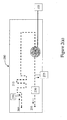
- Figure 1 is a schematic diagram of the microfluidic system of the present invention.
- Figures 2(a), (b) and (c) are schematic diagrams of the substrate of the microfluidic system of the present invention.
- Figure 3 is a schematic showing a detail of a reagent reservoir having a spiral channel.
- Figure 4 is a schematic diagram showing one method of manufacturing the present invention.
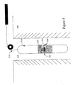
- Figure 5 is a schematic diagram of one application of the present invention, useful in the oilfield and water management areas.
- Figure 6 is a schematic diagram showing various suitable telemetry methods.
- Figure 1 is a schematic of the autonomous microfluidic system 10 of the present invention having a microfluidic substrate 200 in communication with a housing 100.
- the substrate 200 is hermetically sealed to the housing 100 such that the sample inlet 205 extends outside of the housing 100 and the electrical connections 120 are within the housing 100.
- the housing 100 further includes a power supply 105 and control electronics 110 in electrical connection with the substrate 200. It is noted that while reservoir 210 is shown in this figure outside the housing 100 and the waste collector 225 is shown inside the housing 100, the location of these components relative to the housing will depend on the desired configuration of the system. Alternatively, the waste fluid may be discharged via outlet 235. Accordingly, the configuration of Figure 1 is intended to be illustrative and non-limiting. Most preferably, the housing 100 is bonded 115 directly to the substrate 200 avoiding electrical feedthroughs.
- Figures 2(a)-(c) are detailed schematics showing non-limiting embodiments of the substrate 200. More particularly, Figure 2(a) depicts the substrate 200 having fluid channels (dashed lines), optical fibers (dotted lines), and electrical wires (grey lines) embedded therein. Fluids enter the system via sample inlet 205 and mixes with reagent stored in the reagent reservoir 210 in mixing region 215. To minimize particulate in the system, a filter (not shown) may be placed over, attached to, or embedded in, the inlet. The fluid in the system is subject to a driving force, which may be passive or active.
- a driving force which may be passive or active.
- the fluid may be moved through the system using a pump 220 (such as an ultrasonic pump or a piezo-electric pump) operated by control electronics 110 and a power source 105.
- the pump is a piezo-electric pump that is pressure-balanced, such as by applying a water impervious, electrically isolating gel on the surface of the piezo.
- the system may be designed such that the pump pulls or pushes the fluid through the system, or designed such that the pump pulls a portion of the fluid and pushes another portion of the fluid.
- the arrows are intended to show the direction of fluid flow.
- fluid may be moved through the substrate using a passive fluid drive means wherein the differential in pressure between the sampling environment and the pressure within the tool housing is used to move the fluid through the system (such as by lowering the pressure within the submersible housing relative to the sampling environment).
- the sample may be stored in a collector 225 for later use or disposal, or discharged back into the borehole via outlet 235.
- the sample may be 'cleaned' (i.e., reagents or precipitates removed to an acceptable level) prior to discharge using a separator means 230, having, for example, activated charcoal or an ion membrane.
- the separator means 230 may be embedded on the substrate or may be positioned to the outside of the outlet such that the sample passes through the separator means prior to discharge.
- the reagent reservoir 210 preferably has a pressure-balanced contact with the environment to ensure that the reagent is subject to the same pressure as the sample.
- This pressure-balanced contact might be, for example, a flexible impermeable foil or a mechanical pressure adapter.
- the pressure equilibrium prevents back flow through the microfluidic device and reduces the pressure difference to be overcome by the pump.
- the reagent in the reservoir can be, for example, a pH-sensitive color indicator or other reagents or catalysts applicable to the chemical analyses desired.
- the reagent reservoir 210 is connected to the fluid handling system, such as through a permanently open connection or a controlled connection such as with a valve. It is noted that the overall system is inherently pressure-balanced as the inlet and the outlet are exposed to the sampling environment.
- the system may be designed to control the flow rate, sample volumes, and mixing ratios by adjusting the fluid resistance of the system. Because the total flow rate is dependent on the fluid resistance of the complete circuitry, dimensional variation (shape and geometry of the channels, for example) in the system will influence the total fluid resistance and thus the flow rate. To ensure that adequate mixing of the sample with the reagent over a relatively short channel length, various mixing and channel geometries may be used.
- One useful geometry is the herringbone geometry as described by Strook et al. in "Chaotic Mixer for Microchannels", Science, Vol. 295, pages 647-651 (2002) (incorporated by reference herein in its entirety).
- the fluid circuitry may be adapted to generate certain reaction time before interrogation. Accordingly, the fluid circuitry may contain multiple reagent reservoirs, fluid resistors and mixers to control fluid flow and mixing or to create subsequent reactions (such as multistage reactions with variable reaction times).
- Figures 2(b) and 2(c) show alternate embodiments of the present invention.
- Figure 2(b) shows the microfluidic device of Figure 2(a) with a fluid analyzing means 245 inside housing 100 (such as part of the analysis module of Figure 5).
- a fluid analyzing means 245 inside housing 100 (such as part of the analysis module of Figure 5).
- more than one reagent reservoir may be used (i.e., positioned in parallel or series) to allow more than one analyses to be performed using a single microfluidic system.
- the reagents may be stored in a collapsible bag, or a threaded bag as shown in Figure 3, to minimize backflow through the substrate.
- this embodiment shows the fluid analysis means 245 in the housing 100 and connected to the substrate 200 , the fluid analysis means 245 may be embedded directly into the substrate 200 (see, for example, Figure 2(c)).
- the fluid analyzing means 245 is an optical interrogation zone 245a having a light source 245b and a detector 245c.
- the light source 245b and detector 245c may be either embedded in the substrate or connected via optical fibers (as shown).
- the light source 245b transmits lights through the optical interrogation zone 245a to the detector 245c.
- the light source 245b may be any incandescent lamp, LED, laser, etc. suitable for the analysis to be performed.
- the detector 245c measures the transmitted light at a defined wavelength depending on the analysis performed and the source 245b used.
- the detector 245c can be a spectrum analyzer or a combination of appropriate filters and photodiodes.
- Light source 245b and detector 245c are controlled by electronics 110, which may include a microprocessor to process the data and store the measurement values. It is noted that if cyclic olefin copolymer (COC) or any optically clear material is used as the substrate, then no separate optical windows are needed; COC may be used as the optical window.
- COC cyclic olefin copolymer
- FIG. 3 is a schematic of a most preferred embodiment of the reagent reservoir 210, hereinafter referred to as a threaded reagent reservoir.
- This embodiment includes a spiral channel 250 having an opening at the top at 255 such that the channel is pressure balanced relative to the sampling environment.
- a channel 260 extends through the threaded portion to allow the reagent reservoir to be filled and capped 265. Reagent passes from the reservoir into the channels of the substrate via outlet 270.
- the fluid analyzing system may be designed to perform resistivity tests, determine the presence of specific precipitate (such as metal or salt precipitates) or perform other chemical analyses.
- fluid analyses may take place at more than one interrogation zone (not shown), placed in parallel or in series.
- multiple reagents may be used to allow for multiple analyses.
- One particularly useful downhole fluid analysis is pH indication.
- the present invention was tested wherein the interrogation zone was a colorimetric (i.e. optical) pH indicator.
- the results of this test are provided in Table 1, wherein a sample with a known pH was measured using the present invention and compared to measurements taken with standard laboratory equipment (in this case a Spectroquant® Vega 400 photometer): Table 1 Certified Buffer pH Measurement using Vega 400 Measurement using the present invention 4.00 3.98 3.97 5.00 4.90 5.01 6.00 not taken 5.98 6.86 6.78 6.84 7.00 6.90 6.97 7.70 7.63 7.67 8.00 7.99 7.97 As can be seen by the data of Table 1, the system of the present invention can take measurements that are comparable to standard laboratory measurements.
- a bubble trap 240 may be positioned between the mixing region 215 and the optical interrogation zone 245a.
- the entire system is preferably manufactured using MEMS/MOEMS techniques such that all or nearly all connections are eliminated. Accordingly, most bubble sources are naturally eliminated in the design. However, the bubble trap 240 may be used to remove any remaining bubbles and ensure the integrity of the optical measurements.
- the microfluidic device described herein is preferably designed and manufactured so that all channels, tubes and fibers are embedded in a single substrate, such as that possible using MEMS/MOEMS techniques.
- Suitable substrates include (but are not limited to) silicon, quartz, and plastic.
- the substrate may be constructed of plastic using micro-molding techniques wherein a mold is made by machining a piece of metal. The plastic is then formed using the mold and appropriately cured, if needed.
- a second substrate 200b may be attached to 200a where a surface-to-surface bond is applied such that the channels 250 are preserved.
- Adheisve such as UV curable adhesive, may be used.
- a mask may be used to selectively cure the glue in areas of interest.
- the mask allows preferential transmission of UV light such that the glue does not cure in the area of the channels, but cures where desired.
- laser welds may be used.
- substrate is formed of plastic and chemical bonds are used which minimizes dimensional variations due to the layer of glue and complexity of laser welding.
- channel surfaces within the optical interrogation zone may require optical grade polishing to nano-meter scale. For plastic molding, this can be achieved by making the corresponding surface of the mold to be of optical quality polish.
- All tubes and fibers should preferably extend from the substrate at a common end such that they may be isolated in a common waterproof housing. This configuration also allows the device to be easily adapted for fitting in various sampling tools, such as those typically used to monitor aquifers and groundwater as well as those used in the oilfield.
- the present invention may be implemented in a laboratory or in various downhole fluid analysis tools.
- the apparatus described in commonly owned co-pending United States Patent Application Serial No. 10/667,639 filed September 22, 2003, entitled “Determining Fluid Chemistry of Formation Fluid by Downhole Reagent Injection Spectral Analysis” (incorporated by reference herein in its entirety) is a preferred implementation of the present reagent mixture.
- One non-limiting embodiment of the present invention is a wireline formation tester 310, including fluids analyzer 320.
- the formation tester is shown downhole within fluid-filled borehole 305 in formation 300 suspended by logging cable 315.
- Logging cable 315 also couples the formation tester to surface system.
- the housing in this example is the formation tester 310 having a fluids analyzer module 320 with the substrate 200.
- the substrate 200 is affixed to the formation tester 310 in the area of the fluids analyzer module 320 such that the electrical connections 120 are isolated within the tool and the inlet of the microfluidic device (not shown) extends into a fluid flow line 325.
- the power supply and control electronics (not shown) are within the formation tester 310. This configuration eliminates the need to separate pumps, probes and reagent containers.
- Figure 5 is intended to depict a non-limiting embodiment useful for deploying the present invention in the oilfield.
- Other suitable elements may be included as dependent upon the specific application.
- other configurations may be used to extract fluids such as in water or waste water management.
- the substrate may be affixed to tools usually deployed in groundwater monitoring wells such as the Diver® by Van Essen Instruments, chemical processes plants, or producing wells.
- the device may be permanently or semi-permanently installed in these environments.
- the microfluidic device can be used to perform fluid analysis on any fluid sample obtained remotely where space and sample volume is of concern.
- the device may be used in processing plants, for space applications or in a downhole oilfield or water management applications.
- the microfluidic system of the present invention is robust for long term, semi-permanent and permanent applications (on the order of days, months, and years).
- the microfluidic device 100 may communicate with remote equipment via one of the many telemetry schemes known in the art, such as over electronic conductors, optical fibers or other suitable medium to a computer or other remote processing/data storage means 110; it may store the data retrieved from the sensors in the incorporated memory (not shown) to be later retrieved; or it may be transmitted wirelessly 415; or it may be downloaded to a local or remote computer 410.
- a computer or other remote processing/data storage means 110 may store the data retrieved from the sensors in the incorporated memory (not shown) to be later retrieved; or it may be transmitted wirelessly 415; or it may be downloaded to a local or remote computer 410.
Abstract
Description
- The present invention relates to a chemical analysis system and, more particularly, to the use of self-supporting microfluidic systems for chemical analysis of water or mixtures of water and oil.
- In oil well evaluation and aquifer management, quantitative analyses of formation fluid are typically performed in a laboratory environment, the samples having been collected remotely. Standard laboratory procedures are available for quantitative analyses by adding a reagent to chemically react with a specific target species in a sample to cause detectible changes in fluid property such as color, absorption spectra, turbidity, electrical conductivity, etc. See Vogel, A. I., "TextBook of Quantitative Inorganic Analysis, 3rd Edition", Chapter 10-12, John Wiley, 1961, incorporated by reference herein in its entirety. Such changes in fluid property may be caused, for example, by the formation of a product that absorbs light at a certain wavelength, or by the formation of an insoluble product that causes turbidity, or bubbles out as gas. For example, addition of pH sensitive dyes is used for colorimetric pH determination of water samples. A standard procedure for barium determination requires addition of sodium sulfate reagent to the fluid sample resulting in a sulfate precipitate that can be detected through turbidity measurements. Some of these standard laboratory procedures have been adapted for flow injection analysis (Ruzicka et al., Flow Injection Analysis, Chapters 1 and 2, John Wiley, 1981, incorporated by reference herein in its entirety). Flow injection analysis "is based on the injection of a liquid sample into a moving non-segmented continuous carrier stream of a suitable liquid" (see Ruzicka et al., Chapter 2, page 6).
- Fluid samples collected downhole can undergo various reversible and irreversible phase transitions between the point of collection and the point of analysis as pressure and temperature conditions are hard to preserve. Concentrations of constituent species may change because of loss due to vaporization, precipitation etc., and hence the analysis as done in the laboratories may not be representative of true conditions. For example, water chemistry and pH are important for estimating scaling tendencies and corrosion; however, the pH can change substantially as the fluid flows to the surface. Likewise, scaling out of salts and loss of carbon dioxide and hydrogen sulfide can give misleading pH values when laboratory measurements are made on downhole-collected samples. Conventional methods and apparatuses require bulky components that are not efficiently miniaturized for downhole applications.
- Further, fluid sample for water management requires very frequent (i.e. daily, twice daily, etc.) monitoring and measuring of fluid properties. These monitoring regimes include permanent subsurface systems that are designed solely to gather and store frequently acquired data over long periods of time. Accordingly, there is a need for a system that uses very low quantities of reagent, operates autonomously, and collects or neutralizes waste product. Traditional solutions include chemical sensors that tend to lose calibration over a relatively short period of time.
- As will be described in more detail below, the present invention applies MEMS/MOEMS techniques to develop microfluidic devices overcoming the limitations of the prior art. Micro electromechanical systems (MEMS) are well known as microfluidic devices for chemical applications since the 1990's (see Manz et al., "Miniaturized Total Chemical and Analysis Systems: A Novel Concept for Chemical Sensing," Sensors and Actuators B, Vol. B 1, pages 244-248 (1990), incorporated by reference herein in its entirety) and are typically fabricated from silicon, glass, quartz and poly(dimethylsiloxane) (PDMS) (see Verpoorte et al., "Microfluidics Meets MEMS" Proceedings of the IEEE, Vol. 91, pages 930-953 (June 2003), incorporated by reference herein in its entirety). MEMS technology allows for miniaturized designs requiring smaller liquid volumes. In addition, MEMS devices are easy to mass produce having a very accurate reproducibility. MEMS also allows easy integration of different components, such as valves, mixers, channels, etc. Similarly, MEMS systems with optical devices are called MOEMS (micro optical electro mechanical systems, or Optical MEMS). MOEMS have also been used for chemical applications since the 1990's. Commercial (non-chemical) structures are used in the telecommunications field to make use of MEMS wave-guides to modify or route an optical signal.
- For example, United States Patent No. 5,116,759 to Klainer et al. (incorporated by reference herein in its entirety) discloses a laboratory-based system utilizing a MEMS device. In particular, the MEMS device is a cell that receives the sample for analysis. All associated analytical devices, including optical interrogation, power supply, reagent sources, and processing means, are typical laboratory-sized devices not suitable for remote interrogation.
- Accordingly, it is one object of the present invention to provide a novel system to autonomously perform remote chemical analysis.
- It is another object of the present invention to provide a microsystems that will regulate the amounts of sample and reagent to be consumed during each measurement, allowing the use of a reagent reservoir in the downhole instrument and the storage of waste within the instrument.
- It is yet another object of the present invention to provide a microsystem having a total flow rate in the order of microliters per minute, enabling the measurement of pH and use with other reagents for determining the concentration of species like nitrate, heavy metals, scaling ions and hydrocarbons.
- It is yet a further object of the present invention to provide an autonomous system having low power consumption, minimum consumables, neutralized waste material and data logging for in-situ measurements of fluid parameters on a multi-year permanent basis.
- In a first embodiment of the present invention, a microfluidic system for performing fluid analysis is disclosed having: (a) a submersible housing having a fluid analysis means and a power supply to provide power to the system; and (b) a substrate for receiving a fluid sample, having embedded therein a fluid sample inlet, a reagent inlet, a fluid sample outlet, and a mixing region in fluid communication with the fluid sample inlet, the reagent inlet, and the fluid sample outlet, and wherein the substrate includes a fluid drive means for moving the fluid sample through the substrate, and wherein the substrate interconnects with the housing. At least a portion of the fluid analysis means may be embedded in the substrate.
- Fluid is moved through the system using a fluid drive means which may be passive or active. A passive fluid drive system includes a system wherein the fluid is driven due to the differential in pressure between the sampling environment and the internal pressure of the microfluidic device. Active fluid drive systems may include a pump in the housing or embedded in the substrate. Preferably, the pump is a piezo-electric pump embedded in the substrate; most preferably, it is pressure-balanced. At least one reagent reservoir may be connected to the reagent inlet to provide reagents to perform the fluid analysis. It is noted that the substrate may include more than one reagent inlet, wherein each additional inlet has at least one reagent reservoir. Preferably, the reagent reservoirs are collapsible bags, and, most preferably, they are threaded bags.
- To fully pressure-balance the system and ensure efficient fluid handling, the fluid sample inlet and fluid sample outlet may be in fluid communication with the fluid to be sampled. In addition, a separator system may be positioned at the fluid sample outlet to remove particulate from the fluid prior to analysis. The separator system may be embedded in the substrate and may include activated charcoal, an ion exchange membrane, or other means commonly used in the field.
- The system may further comprise a control means to control fluid analysis means to assist in the remote operation of the system. Likewise, data processing means may be used to receive, store, and/or process data from the fluid analysis means. The control means may include data transmission means to transmit data received from the fluid analysis means.
- A second embodiment is a method of performing fluid analysis comprising: (a) remotely deploying a microfluidic system in or proximate to the fluid to be sampled (also referred to as a sampling environment), wherein the microfluidic system is comprised of a submersible housing having a fluid analysis means and a power supply to provide power to the system; and a substrate for receiving a fluid sample, having embedded therein a fluid sample inlet, a reagent inlet, a fluid sample outlet, and a mixing region in fluid communication with the fluid sample inlet, the reagent inlet, and the fluid sample outlet, and wherein the substrate includes a fluid drive means for moving the fluid sample through the substrate, and wherein the substrate interconnects with the housing; (b) receiving a fluid sample into the fluid sample inlet; (c) mixing the fluid sample with reagent from the reagent inlet in the mixing region; and (d) analyzing the fluid sample using the fluid analysis means. The fluid sample may then be stored in the housing for later disposal or discharged back, into the sampling environment.
- The device of the present invention may be manufactured by (a) providing two or more substrates; (b) forming fluid mixing channels and fluid analysis channels within at least one of the substrates; (c) forming an inlet and an outlet within at least one of the substrates; (d) embedding a piezoelectric pump within at least one of the substrates; and (e) bonding the substrates to one another. It is preferred that the optical fibers and electrical wires required for the operation of the pump and the fluid analysis region be embedded within at least one of the substrates.
- The overall system has limited dimensions (such as in diameter and length) and is completely self supporting, enabling remote analysis or monitoring such as in standpipes, aquifers, groundwater, hazardous sites, chemical plants and boreholes. The device is submersible and autonomous. Because the device remains robust over an extended period of time it may be permanently (or semi-permanently) installed in remote locations for extended monitoring.
- The instrument is particularly useful, for example, in oilfield applications for the detection of scale forming ions and dissolved gases and in water applications for the detection of hazardous chemicals. Chemical measurements of interest in the water business include, but is not limited to, pH and toxic chemicals, such as nitrate, arsenic and other heavy metals, benzene and other organic compounds. Chemical measurements of interest in the oilfield include, but is not limited to, the determination of pH, the detection of H2S and CO2, as well as scale forming ions such as Ca, Ba, Sr, Mg, and SO4.
- Further features and applications of the present invention will become more readily apparent from the figures and detailed description that follows.
- Figure 1 is a schematic diagram of the microfluidic system of the present invention.
- Figures 2(a), (b) and (c) are schematic diagrams of the substrate of the microfluidic system of the present invention.
- Figure 3 is a schematic showing a detail of a reagent reservoir having a spiral channel.
- Figure 4 is a schematic diagram showing one method of manufacturing the present invention.
- Figure 5 is a schematic diagram of one application of the present invention, useful in the oilfield and water management areas.
- Figure 6 is a schematic diagram showing various suitable telemetry methods.
- Figure 1 is a schematic of the autonomous
microfluidic system 10 of the present invention having amicrofluidic substrate 200 in communication with ahousing 100. Preferably, thesubstrate 200 is hermetically sealed to thehousing 100 such that thesample inlet 205 extends outside of thehousing 100 and theelectrical connections 120 are within thehousing 100. Thehousing 100 further includes apower supply 105 andcontrol electronics 110 in electrical connection with thesubstrate 200. It is noted that whilereservoir 210 is shown in this figure outside thehousing 100 and thewaste collector 225 is shown inside thehousing 100, the location of these components relative to the housing will depend on the desired configuration of the system. Alternatively, the waste fluid may be discharged viaoutlet 235. Accordingly, the configuration of Figure 1 is intended to be illustrative and non-limiting. Most preferably, thehousing 100 is bonded 115 directly to thesubstrate 200 avoiding electrical feedthroughs. - Figures 2(a)-(c) are detailed schematics showing non-limiting embodiments of the
substrate 200. More particularly, Figure 2(a) depicts thesubstrate 200 having fluid channels (dashed lines), optical fibers (dotted lines), and electrical wires (grey lines) embedded therein. Fluids enter the system viasample inlet 205 and mixes with reagent stored in thereagent reservoir 210 in mixingregion 215. To minimize particulate in the system, a filter (not shown) may be placed over, attached to, or embedded in, the inlet. The fluid in the system is subject to a driving force, which may be passive or active. As shown in Figure 1(a), the fluid may be moved through the system using a pump 220 (such as an ultrasonic pump or a piezo-electric pump) operated bycontrol electronics 110 and apower source 105. Preferably, the pump is a piezo-electric pump that is pressure-balanced, such as by applying a water impervious, electrically isolating gel on the surface of the piezo. The system may be designed such that the pump pulls or pushes the fluid through the system, or designed such that the pump pulls a portion of the fluid and pushes another portion of the fluid. The arrows are intended to show the direction of fluid flow. Alternatively, fluid may be moved through the substrate using a passive fluid drive means wherein the differential in pressure between the sampling environment and the pressure within the tool housing is used to move the fluid through the system (such as by lowering the pressure within the submersible housing relative to the sampling environment). - The sample may be stored in a
collector 225 for later use or disposal, or discharged back into the borehole viaoutlet 235. The sample may be 'cleaned' (i.e., reagents or precipitates removed to an acceptable level) prior to discharge using a separator means 230, having, for example, activated charcoal or an ion membrane. The separator means 230 may be embedded on the substrate or may be positioned to the outside of the outlet such that the sample passes through the separator means prior to discharge. - The
reagent reservoir 210 preferably has a pressure-balanced contact with the environment to ensure that the reagent is subject to the same pressure as the sample. This pressure-balanced contact might be, for example, a flexible impermeable foil or a mechanical pressure adapter. The pressure equilibrium prevents back flow through the microfluidic device and reduces the pressure difference to be overcome by the pump. The reagent in the reservoir can be, for example, a pH-sensitive color indicator or other reagents or catalysts applicable to the chemical analyses desired. Thereagent reservoir 210 is connected to the fluid handling system, such as through a permanently open connection or a controlled connection such as with a valve. It is noted that the overall system is inherently pressure-balanced as the inlet and the outlet are exposed to the sampling environment. - The system may be designed to control the flow rate, sample volumes, and mixing ratios by adjusting the fluid resistance of the system. Because the total flow rate is dependent on the fluid resistance of the complete circuitry, dimensional variation (shape and geometry of the channels, for example) in the system will influence the total fluid resistance and thus the flow rate. To ensure that adequate mixing of the sample with the reagent over a relatively short channel length, various mixing and channel geometries may be used. One useful geometry is the herringbone geometry as described by Strook et al. in "Chaotic Mixer for Microchannels", Science, Vol. 295, pages 647-651 (2002) (incorporated by reference herein in its entirety).
- While only one reagent and mixing region are shown in Figure 2(a), the fluid circuitry may be adapted to generate certain reaction time before interrogation. Accordingly, the fluid circuitry may contain multiple reagent reservoirs, fluid resistors and mixers to control fluid flow and mixing or to create subsequent reactions (such as multistage reactions with variable reaction times).
- Figures 2(b) and 2(c) show alternate embodiments of the present invention. Figure 2(b) shows the microfluidic device of Figure 2(a) with a fluid analyzing means 245 inside housing 100 (such as part of the analysis module of Figure 5). Again, more than one reagent reservoir may be used (i.e., positioned in parallel or series) to allow more than one analyses to be performed using a single microfluidic system. Further, the reagents may be stored in a collapsible bag, or a threaded bag as shown in Figure 3, to minimize backflow through the substrate. While this embodiment shows the fluid analysis means 245 in the
housing 100 and connected to thesubstrate 200, the fluid analysis means 245 may be embedded directly into the substrate 200 (see, for example, Figure 2(c)). - In Figure 2(c) the fluid analyzing means 245 is an
optical interrogation zone 245a having alight source 245b and adetector 245c. Thelight source 245b anddetector 245c may be either embedded in the substrate or connected via optical fibers (as shown). Thelight source 245b transmits lights through theoptical interrogation zone 245a to thedetector 245c. Thelight source 245b, may be any incandescent lamp, LED, laser, etc. suitable for the analysis to be performed. Likewise, thedetector 245c measures the transmitted light at a defined wavelength depending on the analysis performed and thesource 245b used. For example, thedetector 245c can be a spectrum analyzer or a combination of appropriate filters and photodiodes.Light source 245b anddetector 245c are controlled byelectronics 110, which may include a microprocessor to process the data and store the measurement values. It is noted that if cyclic olefin copolymer (COC) or any optically clear material is used as the substrate, then no separate optical windows are needed; COC may be used as the optical window. - As mentioned above, the
reagent reservoir 210 should be pressure balanced with the sampling environment. Figure 3 is a schematic of a most preferred embodiment of thereagent reservoir 210, hereinafter referred to as a threaded reagent reservoir. This embodiment includes aspiral channel 250 having an opening at the top at 255 such that the channel is pressure balanced relative to the sampling environment. Achannel 260 extends through the threaded portion to allow the reagent reservoir to be filled and capped 265. Reagent passes from the reservoir into the channels of the substrate viaoutlet 270. - Alternatively, the fluid analyzing system may be designed to perform resistivity tests, determine the presence of specific precipitate (such as metal or salt precipitates) or perform other chemical analyses.
- It is noted that fluid analyses may take place at more than one interrogation zone (not shown), placed in parallel or in series. As described above, multiple reagents may be used to allow for multiple analyses.
- One particularly useful downhole fluid analysis is pH indication. The present invention was tested wherein the interrogation zone was a colorimetric (i.e. optical) pH indicator. The results of this test are provided in Table 1, wherein a sample with a known pH was measured using the present invention and compared to measurements taken with standard laboratory equipment (in this case a Spectroquant® Vega 400 photometer):
Table 1 Certified Buffer pH Measurement using Vega 400 Measurement using the present invention 4.00 3.98 3.97 5.00 4.90 5.01 6.00 not taken 5.98 6.86 6.78 6.84 7.00 6.90 6.97 7.70 7.63 7.67 8.00 7.99 7.97 - One skilled in the art would recognize that the presence of bubbles in the fluid sample may interfere with optical measurements and capillary pressure. Accordingly, a
bubble trap 240 may be positioned between the mixingregion 215 and theoptical interrogation zone 245a. The entire system is preferably manufactured using MEMS/MOEMS techniques such that all or nearly all connections are eliminated. Accordingly, most bubble sources are naturally eliminated in the design. However, thebubble trap 240 may be used to remove any remaining bubbles and ensure the integrity of the optical measurements. - The microfluidic device described herein is preferably designed and manufactured so that all channels, tubes and fibers are embedded in a single substrate, such as that possible using MEMS/MOEMS techniques. Suitable substrates include (but are not limited to) silicon, quartz, and plastic. For downhole applications, including oilfield and water management applications, the substrate may be constructed of plastic using micro-molding techniques wherein a mold is made by machining a piece of metal. The plastic is then formed using the mold and appropriately cured, if needed. As shown in Figure 4, to close the
channel 250 insubstrate 200a, asecond substrate 200b may be attached to 200a where a surface-to-surface bond is applied such that thechannels 250 are preserved. Adheisve, such as UV curable adhesive, may be used. If UV curable adhesive is used, a mask may be used to selectively cure the glue in areas of interest. The mask allows preferential transmission of UV light such that the glue does not cure in the area of the channels, but cures where desired. In addition, laser welds may be used. Preferably, substrate is formed of plastic and chemical bonds are used which minimizes dimensional variations due to the layer of glue and complexity of laser welding. - It is noted that while only two substrate segments are shown in Figure 4, additional substrate segments may be used to form the microfluidic device of the present invention.
- Depending on the analysis to be performed, it may be preferable to achieve highly polished channel surfaces. For example, if the microfluidic device is to be used for optical interrogation, channel surfaces within the optical interrogation zone may require optical grade polishing to nano-meter scale. For plastic molding, this can be achieved by making the corresponding surface of the mold to be of optical quality polish.
- All tubes and fibers should preferably extend from the substrate at a common end such that they may be isolated in a common waterproof housing. This configuration also allows the device to be easily adapted for fitting in various sampling tools, such as those typically used to monitor aquifers and groundwater as well as those used in the oilfield.
- The present invention may be implemented in a laboratory or in various downhole fluid analysis tools. For example, the apparatus described in commonly owned co-pending United States Patent Application Serial No. 10/667,639 filed September 22, 2003, entitled "Determining Fluid Chemistry of Formation Fluid by Downhole Reagent Injection Spectral Analysis" (incorporated by reference herein in its entirety) is a preferred implementation of the present reagent mixture.
- One non-limiting embodiment of the present invention, as shown in Figure 5, is a
wireline formation tester 310, includingfluids analyzer 320. The formation tester is shown downhole within fluid-filledborehole 305 information 300 suspended by loggingcable 315.Logging cable 315 also couples the formation tester to surface system. The housing in this example is theformation tester 310 having afluids analyzer module 320 with thesubstrate 200. As shown in this figure, thesubstrate 200 is affixed to theformation tester 310 in the area of thefluids analyzer module 320 such that theelectrical connections 120 are isolated within the tool and the inlet of the microfluidic device (not shown) extends into afluid flow line 325. The power supply and control electronics (not shown) are within theformation tester 310. This configuration eliminates the need to separate pumps, probes and reagent containers. - It is noted that Figure 5 is intended to depict a non-limiting embodiment useful for deploying the present invention in the oilfield. Other suitable elements may be included as dependent upon the specific application. For example, other configurations may be used to extract fluids such as in water or waste water management. The substrate may be affixed to tools usually deployed in groundwater monitoring wells such as the Diver® by Van Essen Instruments, chemical processes plants, or producing wells. Likewise, the device may be permanently or semi-permanently installed in these environments.
- It is envisioned that the microfluidic device can be used to perform fluid analysis on any fluid sample obtained remotely where space and sample volume is of concern. For example, the device may be used in processing plants, for space applications or in a downhole oilfield or water management applications. In addition, the microfluidic system of the present invention is robust for long term, semi-permanent and permanent applications (on the order of days, months, and years). Accordingly, as shown in Figure 6, the
microfluidic device 100 may communicate with remote equipment via one of the many telemetry schemes known in the art, such as over electronic conductors, optical fibers or other suitable medium to a computer or other remote processing/data storage means 110; it may store the data retrieved from the sensors in the incorporated memory (not shown) to be later retrieved; or it may be transmitted wirelessly 415; or it may be downloaded to a local orremote computer 410. - While the invention has been described herein with reference to certain examples and embodiments, it will be evident that various modifications and changes may be made to the embodiments described above without departing from the scope and spirit of the invention as set forth in the claims.
Claims (44)
- A microfluidic system for performing fluid analysis, comprised of:a submersible housing having a fluid analysis means and a power supply to provide power to said system; anda substrate for receiving a fluid sample, having embedded therein a fluid sample inlet, a reagent inlet, a fluid sample outlet, and a mixing region in fluid communication with said fluid sample inlet, said reagent inlet, and said fluid sample outlet, and wherein said substrate includes a fluid drive means for moving the fluid sample through said substrate, and wherein said substrate interconnects with said housing.
- The system of claim 1, wherein at least a portion of the fluid analysis means is embedded in said substrate.
- The system of claim 1, wherein said fluid sample inlet, said reagent inlet, and said fluid sample outlet are connected via channels embedded in the substrate.
- The system of claim 1, wherein said fluid drive means is a result of the differential pressure between the sampling environment pressure and the pressure of the system.
- The system of claim 4, wherein the pressure of the system is less than the pressure of the sampling environment.
- The system of claim 1, wherein said fluid drive means is a pump.
- The system of claim 6, wherein said pump is embedded in said substrate.
- The system of claim 7, wherein said pump is a piezo-electric pump.
- The system of claim 8, wherein said pump is pressure balanced.
- The system of claim 1, wherein at least one reagent reservoir is connected to said reagent inlet.
- The system of claim 1, further comprising one or more additional reagent inlets, each additional inlet having at least one reagent reservoir.
- The system of claim 11, wherein said reagent reservoirs are collapsible bags.
- The system of claim 11, wherein said reagent reservoirs are threaded.
- The system of claim 1, further comprising one or more additional fluid analysis means in fluid communication with said substrate.
- The system of claim 1, further comprising a bubble trap embedded in said substrate and positioned between said mixing region and said fluid analysis means.
- The system of claim 1, wherein said fluid analysis means is an optical interrogation means.
- The system of claim 16, wherein said optical interrogation means includes an optical interrogation region that is embedded in said substrate.
- The system of claim 17, wherein said optical interrogation means includes a light source and a detector.
- The system of claim 18, wherein optical fibers of said light source and said detector are embedded in said substrate.
- The system of claim 1, wherein said a storage chamber is positioned in fluid communication with said fluid sample outlet.
- The system of claim 1, wherein said fluid sample inlet and said fluid sample outlet is in fluid communication with the fluid to be sampled.
- The system of claim 21, further comprising a separator system positioned at said fluid sample outlet.
- The system of claim 22, wherein said separator system is embedded in said substrate.
- The system of claim 22, wherein said separator system includes activated charcoal.
- The system of claim 24, wherein said activated charcoal is embedded in said substrate.
- The system of claim 22, wherein said separator system includes an ion exchange membrane.
- The system of claim 26, wherein said ion exchange membrane is embedded in said substrate.
- The system of claim 1, wherein said substrate is comprised of plastic.
- The system of claim 1, wherein said substrate is comprise of an optically clear material.
- The system of claim 1, wherein said substrate is comprised of cyclic olefin copolymer.
- The system of claim 1, wherein said substrate is manufactured using micro-molding techniques.
- The system of claim 1, further comprising a control means to control said fluid analysis means.
- The system of claim 32, wherein said control means further includes data processing means to receive data from said fluid analysis means.
- The system of claim 33, wherein said processing means further include means to store data.
- The system of claim 32, wherein said control means further includes data transmission means to transmit data from said fluid analysis means.
- The system of claim 1, wherein said submersible housing is adapted for connection to a downhole analysis tool.
- The system of claim 36, wherein said downhole analysis tool is selected from the group consisting of a oilfield characterization tool, a groundwater monitoring tool, or a permanent or semi-permanent monitoring system.
- A method of performing fluid analysis comprising:a. remotely deploying a microfluidic system in a sampling environment, wherein said microfluidic system is comprised of a submersible housing having a fluid analysis means and a power supply to provide power to said system; and a substrate for receiving a fluid sample, having embedded therein a fluid sample inlet, a reagent inlet, a fluid sample outlet, and a mixing region in fluid communication with said fluid sample inlet, said reagent inlet, and said fluid sample outlet, and wherein said substrate includes a fluid drive means for moving the fluid sample through said substrate, and wherein said substrate interconnects with said housing;b. receiving a fluid sample into said fluid sample inlet;c. mixing said fluid sample with reagent from said reagent inlet in said mixing region; andd. analyzing said fluid sample using said fluid analysis means.
- The method of claim 38, wherein analyzing said fluid sample includes performing optical measurements on said fluid.
- The method of claim 39, further comprising removing bubbles from said fluid sample prior to performing optical measurements.
- The method of claim 38, further comprising processing data from said fluid analysis means.
- The method of claim 41, further comprising transmitting data from said fluid analysis means.
- The method of claim 38, further comprising discharging the fluid sample into the sampling environment.
- The method of claim 43, further comprising separating reagent or precipitate from said fluid sample prior to discharging the fluid sample into the sampling environment.
Applications Claiming Priority (1)
| Application Number | Priority Date | Filing Date | Title |
|---|---|---|---|
| US10/885,471 US7799278B2 (en) | 2004-07-06 | 2004-07-06 | Microfluidic system for chemical analysis |
Publications (3)
| Publication Number | Publication Date |
|---|---|
| EP1614465A1 true EP1614465A1 (en) | 2006-01-11 |
| EP1614465B1 EP1614465B1 (en) | 2007-08-29 |
| EP1614465B8 EP1614465B8 (en) | 2008-02-20 |
Family
ID=34938366
Family Applications (1)
| Application Number | Title | Priority Date | Filing Date |
|---|---|---|---|
| EP05076524A Not-in-force EP1614465B8 (en) | 2004-07-06 | 2005-07-04 | Microfluidic system for chemical analysis |
Country Status (5)
| Country | Link |
|---|---|
| US (1) | US7799278B2 (en) |
| EP (1) | EP1614465B8 (en) |
| AT (1) | ATE371498T1 (en) |
| CA (1) | CA2511454C (en) |
| DE (1) | DE602005002196D1 (en) |
Cited By (4)
| Publication number | Priority date | Publication date | Assignee | Title |
|---|---|---|---|---|
| WO2007102783A1 (en) * | 2006-03-07 | 2007-09-13 | Nanyang Technological University | Microfluidic immunoassay device |
| EP2075403A1 (en) | 2007-12-27 | 2009-07-01 | PRAD Research and Development N.V. | Real-time measurement of reservoir fluid properties |
| US7575681B2 (en) * | 2004-07-06 | 2009-08-18 | Schlumberger Technology Corporation | Microfluidic separator |
| US10175380B2 (en) | 2013-04-18 | 2019-01-08 | Halliburton Energy Services, Inc. | Device and method for parallel microfluidic pressure-volume-temperature analysis |
Families Citing this family (36)
| Publication number | Priority date | Publication date | Assignee | Title |
|---|---|---|---|---|
| GB0122929D0 (en) * | 2001-09-24 | 2001-11-14 | Abb Offshore Systems Ltd | Sondes |
| SE0400662D0 (en) * | 2004-03-24 | 2004-03-24 | Aamic Ab | Assay device and method |
| JP4683538B2 (en) * | 2004-05-06 | 2011-05-18 | セイコーインスツル株式会社 | Analysis system and analysis method including microchip for analysis |
| US8262909B2 (en) * | 2004-07-06 | 2012-09-11 | Schlumberger Technology Corporation | Methods and devices for minimizing membrane fouling for microfluidic separators |
| US20060198742A1 (en) * | 2005-03-07 | 2006-09-07 | Baker Hughes, Incorporated | Downhole uses of piezoelectric motors |
| CA2557380C (en) * | 2005-08-27 | 2012-09-25 | Schlumberger Canada Limited | Time-of-flight stochastic correlation measurements |
| US7600413B2 (en) * | 2006-11-29 | 2009-10-13 | Schlumberger Technology Corporation | Gas chromatography system architecture |
| US20080245740A1 (en) * | 2007-01-29 | 2008-10-09 | Searete Llc, A Limited Liability Corporation Of The State Of Delaware | Fluidic methods |
| US7784330B2 (en) * | 2007-10-05 | 2010-08-31 | Schlumberger Technology Corporation | Viscosity measurement |
| US7574898B2 (en) * | 2007-11-08 | 2009-08-18 | Schlumberger Technology Corporation | Vibrating wire viscosity sensor |
| US20090120168A1 (en) * | 2007-11-08 | 2009-05-14 | Schlumberger Technology Corporation | Microfluidic downhole density and viscosity sensor |
| US20110039033A1 (en) * | 2008-01-31 | 2011-02-17 | Erika Merschrod | Method of depositing a polymer micropattern on a substrate |
| US8340913B2 (en) * | 2008-03-03 | 2012-12-25 | Schlumberger Technology Corporation | Phase behavior analysis using a microfluidic platform |
| CA2623793C (en) * | 2008-03-03 | 2010-11-23 | Schlumberger Canada Limited | Microfluidic apparatus and method for measuring thermo-physical properties of a reservoir fluid |
| WO2009120642A1 (en) * | 2008-03-26 | 2009-10-01 | Massachusetts Institute Of Technology | Methods for fabricating electrokinetic concentration devices |
| US9051821B2 (en) * | 2008-12-15 | 2015-06-09 | Schlumberger Technology Corporation | Microfluidic methods and apparatus to perform in situ chemical detection |
| US8564768B2 (en) * | 2009-04-17 | 2013-10-22 | Schlumberger Technology Corporation | High pressure and high temperature optical spectroscopy cell using spherical surfaced lenses in direct contact with a fluid pathway |
| US20100269579A1 (en) * | 2009-04-22 | 2010-10-28 | Schlumberger Technology Corporation | Detecting gas compounds for downhole fluid analysis using microfluidics and reagent with optical signature |
| WO2010135852A1 (en) * | 2009-05-27 | 2010-12-02 | 西门子公司 | Capillary electrophoresis chip, apparatus and method suitable for online application |
| US8380446B2 (en) | 2010-06-14 | 2013-02-19 | Schlumberger Technology Corporation | System and method for determining the phase envelope of a gas condensate |
| US8826981B2 (en) * | 2011-09-28 | 2014-09-09 | Schlumberger Technology Corporation | System and method for fluid processing with variable delivery for downhole fluid analysis |
| FR2981283B1 (en) * | 2011-10-13 | 2014-08-29 | Chambre De Commerce Et De L Ind De Paris Au Titre De Son Etablissement D Enseignement Superieur Esie | MICROFLUIDIC DEVICE FOR ANALYZING A FLUID UNDER PRESSURE. |
| US20130175036A1 (en) * | 2012-01-10 | 2013-07-11 | Andreas Hausot | Methods and Apparatus for Downhole Extraction and Analysis of Heavy Oil |
| US9249661B2 (en) | 2012-01-20 | 2016-02-02 | Schlumberger Technology Corporation | Apparatus and methods for determining commingling compatibility of fluids from different formation zones |
| CA2911503C (en) * | 2013-09-20 | 2020-10-06 | Schlumberger Canada Limited | Microfluidic determination of wax appearance temperature |
| EP2878374B1 (en) | 2013-11-29 | 2021-05-12 | IMEC vzw | Method for performing digital PCR |
| US9863881B2 (en) * | 2014-01-15 | 2018-01-09 | Purdue Research Foundation | Methods for measuring concentrations of analytes in turbid solutions by applying turbidity corrections to raman observations |
| KR101562318B1 (en) * | 2014-02-10 | 2015-10-22 | 나노바이오시스 주식회사 | Microfluidic chip and real-time analyzing apparatus using the same |
| US10018040B2 (en) | 2014-10-24 | 2018-07-10 | Schlumberger Technology Corporation | System and methodology for chemical constituent sensing and analysis |
| WO2017061986A1 (en) * | 2015-10-06 | 2017-04-13 | Halliburton Energy Services, Inc. | Methods and systems using micro-photomultiplier tubes and microfluidics with integrated computational elements |
| US10934512B2 (en) * | 2015-11-26 | 2021-03-02 | Pusan National University Industry-University Cooperation Foundation | Microfluidic perfusion cell culture system |
| US11358140B2 (en) * | 2017-05-16 | 2022-06-14 | Autonomous Medical Devices Inc. | Apparatus for automatic sampling of biological species employing an amplification with a magnetic nanoparticle and propulsion method |
| US11039765B2 (en) * | 2017-09-26 | 2021-06-22 | International Business Machines Corporation | Smart pellet for sample testing |
| CN111220625B (en) * | 2020-01-18 | 2023-04-07 | 哈尔滨工业大学 | Surface and sub-surface integrated confocal microscopic measurement device and method |
| CN113063779A (en) * | 2021-03-15 | 2021-07-02 | 埃妥生物科技(杭州)有限公司 | Sampler and mixing device of sample and reagent |
| CN116930541A (en) * | 2023-09-14 | 2023-10-24 | 深圳希克生物医疗科技有限公司 | Method for detecting biological fluid sample, control device, detection instrument and medium |
Citations (4)
| Publication number | Priority date | Publication date | Assignee | Title |
|---|---|---|---|---|
| US5116759A (en) | 1990-06-27 | 1992-05-26 | Fiberchem Inc. | Reservoir chemical sensors |
| US5984023A (en) * | 1996-07-26 | 1999-11-16 | Advanced Coring Technology | Downhole in-situ measurement of physical and or chemical properties including fluid saturations of cores while coring |
| WO2002077613A2 (en) * | 2001-03-23 | 2002-10-03 | Services Petroliers Schlumberger | Fluid property sensors |
| US20040129874A1 (en) | 2002-11-22 | 2004-07-08 | Schlumberger Technology Corporation | Determining fluid chemistry of formation fluid by downhole reagent injection spectral analysis |
Family Cites Families (14)
| Publication number | Priority date | Publication date | Assignee | Title |
|---|---|---|---|---|
| EP0517228B1 (en) * | 1991-06-07 | 1995-12-27 | Asahi Glass Company Ltd. | Method for separating and recovering an acid |
| CA2142010C (en) * | 1992-08-10 | 2002-01-08 | Dorit Zitzelsberger | Process and device for the biological treatment of organically polluted waste water and organic waste |
| US6074827A (en) * | 1996-07-30 | 2000-06-13 | Aclara Biosciences, Inc. | Microfluidic method for nucleic acid purification and processing |
| US6039897A (en) * | 1996-08-28 | 2000-03-21 | University Of Washington | Multiple patterned structures on a single substrate fabricated by elastomeric micro-molding techniques |
| US6306590B1 (en) * | 1998-06-08 | 2001-10-23 | Caliper Technologies Corp. | Microfluidic matrix localization apparatus and methods |
| US6262519B1 (en) * | 1998-06-19 | 2001-07-17 | Eastman Kodak Company | Method of controlling fluid flow in a microfluidic process |
| GB9821573D0 (en) | 1998-10-02 | 1998-11-25 | Central Research Lab Ltd | Method and apparatus for removing a substance from a container |
| DE19941271A1 (en) | 1999-08-31 | 2001-04-05 | Lienhard Pagel | Micro-fluid membrane module used in pH regulating systems has gas-permeable permeation membrane between micro-fluidic channels |
| US20020164816A1 (en) * | 2001-04-06 | 2002-11-07 | California Institute Of Technology | Microfluidic sample separation device |
| US6919046B2 (en) | 2001-06-07 | 2005-07-19 | Nanostream, Inc. | Microfluidic analytical devices and methods |
| US6848462B2 (en) | 2001-12-06 | 2005-02-01 | Nanostream, Inc. | Adhesiveless microfluidic device fabrication |
| JP4039481B2 (en) | 2001-12-26 | 2008-01-30 | 財団法人川村理化学研究所 | Method for manufacturing microfluidic device having porous part |
| US20030150791A1 (en) | 2002-02-13 | 2003-08-14 | Cho Steven T. | Micro-fluidic anti-microbial filter |
| US8075778B2 (en) | 2003-03-25 | 2011-12-13 | Massachusetts Institute Of Technology | Fluid separation |
-
2004
- 2004-07-06 US US10/885,471 patent/US7799278B2/en active Active
-
2005
- 2005-07-04 AT AT05076524T patent/ATE371498T1/en not_active IP Right Cessation
- 2005-07-04 DE DE602005002196T patent/DE602005002196D1/en active Active
- 2005-07-04 EP EP05076524A patent/EP1614465B8/en not_active Not-in-force
- 2005-07-05 CA CA2511454A patent/CA2511454C/en not_active Expired - Fee Related
Patent Citations (4)
| Publication number | Priority date | Publication date | Assignee | Title |
|---|---|---|---|---|
| US5116759A (en) | 1990-06-27 | 1992-05-26 | Fiberchem Inc. | Reservoir chemical sensors |
| US5984023A (en) * | 1996-07-26 | 1999-11-16 | Advanced Coring Technology | Downhole in-situ measurement of physical and or chemical properties including fluid saturations of cores while coring |
| WO2002077613A2 (en) * | 2001-03-23 | 2002-10-03 | Services Petroliers Schlumberger | Fluid property sensors |
| US20040129874A1 (en) | 2002-11-22 | 2004-07-08 | Schlumberger Technology Corporation | Determining fluid chemistry of formation fluid by downhole reagent injection spectral analysis |
Non-Patent Citations (5)
| Title |
|---|
| MANZ: "Miniaturized Total Chemical and Analysis Systems: A Novel Concept for Chemical Sensing", SENSORS AND ACTUATORS B, vol. B1, pages 244 - 248 |
| RUZICKA: "FLOW INJECTION ANALYSIS", 1981, JOHN WILEY |
| STROOK: "Chaotic Mixer for Microchannels", SCIENCE, vol. 295, 2002, pages 647 - 651 |
| VERPOORTE: "Microfluidics Meets MEMS", IEEE, vol. 91, pages 930 - 953, XP002334969, DOI: doi:10.1109/JPROC.2003.813570 |
| VOGEL, A. I.: "TEXT- BOOK OF QUANTITATIVE INORGANIC ANALYSIS, 3RD EDITION", 1961, JOHN WILEY |
Cited By (10)
| Publication number | Priority date | Publication date | Assignee | Title |
|---|---|---|---|---|
| US7575681B2 (en) * | 2004-07-06 | 2009-08-18 | Schlumberger Technology Corporation | Microfluidic separator |
| WO2007102783A1 (en) * | 2006-03-07 | 2007-09-13 | Nanyang Technological University | Microfluidic immunoassay device |
| US8158363B2 (en) | 2006-03-07 | 2012-04-17 | Nanyang Technological University | Microfluidic immunoassay device |
| EP2075403A1 (en) | 2007-12-27 | 2009-07-01 | PRAD Research and Development N.V. | Real-time measurement of reservoir fluid properties |
| WO2009083243A1 (en) * | 2007-12-27 | 2009-07-09 | Services Petroliers Schlumberger | Real-time measurement of reservoir fluid properties |
| US9696193B2 (en) | 2007-12-27 | 2017-07-04 | Schlumberger Technology Corporation | Real-time measurement of reservoir fluid properties |
| US10175380B2 (en) | 2013-04-18 | 2019-01-08 | Halliburton Energy Services, Inc. | Device and method for parallel microfluidic pressure-volume-temperature analysis |
| US11327197B2 (en) | 2013-04-18 | 2022-05-10 | Halliburton Energy Services, Inc. | Device and method for parallel pressure-volume-temperature analysis using gas chromatography and mass spectrometry |
| US11635541B2 (en) | 2013-04-18 | 2023-04-25 | Halliburton Energy Services, Inc. | Microfluidic device and method for parallel pressure-volume-temperature analysis in reservoir simulations |
| US11774623B2 (en) | 2013-04-18 | 2023-10-03 | Halliburton Energy Services, Inc. | Microfluidic device and method for parallel pressure-volume-temperature analysis in reservoir simulations |
Also Published As
| Publication number | Publication date |
|---|---|
| CA2511454A1 (en) | 2006-01-06 |
| ATE371498T1 (en) | 2007-09-15 |
| US20060008382A1 (en) | 2006-01-12 |
| EP1614465B1 (en) | 2007-08-29 |
| CA2511454C (en) | 2015-11-24 |
| DE602005002196D1 (en) | 2007-10-11 |
| EP1614465B8 (en) | 2008-02-20 |
| US7799278B2 (en) | 2010-09-21 |
Similar Documents
| Publication | Publication Date | Title |
|---|---|---|
| EP1614465B1 (en) | Microfluidic system for chemical analysis | |
| US7575681B2 (en) | Microfluidic separator | |
| US9389158B2 (en) | Passive micro-vessel and sensor | |
| US8262909B2 (en) | Methods and devices for minimizing membrane fouling for microfluidic separators | |
| US9051821B2 (en) | Microfluidic methods and apparatus to perform in situ chemical detection | |
| US20140024073A1 (en) | Bio-mems for downhole fluid analysis | |
| US20100210008A1 (en) | Configurable Microfluidic Substrate Assembly | |
| EA021134B1 (en) | Detecting gas compounds for downhole fluid analysis using microfluidics and reagent with optical signature | |
| EP3168595B1 (en) | System and method for acquiring samples in a body of fluid | |
| US11015430B2 (en) | Passive micro-vessel and sensor | |
| US20190323345A1 (en) | Flushing microfluidic sensor systems | |
| WO2004110647A2 (en) | Microfluidic water analytical device | |
| US10208591B2 (en) | Flushing microfluidic sensor systems | |
| Bowden et al. | A prototype industrial sensing system for phosphorus based on micro system technology | |
| EP3740746A1 (en) | Passive micro-vessel and sensor | |
| EP2953677B1 (en) | Passive micro-vessel and sensor for viscosity determination | |
| US20140001114A1 (en) | Fluid Filters | |
| Koch | Micro total analysis system for in-situ and autonomous spectrophotometric monitoring of iron in groundwater | |
| Sieben et al. | Autonomous microfluidic sensors for nutrient detection: applied to nitrite, nitrate, phosphate, manganese and iron | |
| Tavernier et al. | Microsystem With Fluidic and Optical Interface for Inline Measurement of ${\rm CO} _ {2} $ in Oil Fields | |
| Kim et al. | Microfabrication of a multichannel microfluidic system for use with microbead reagent sources and detectors |
Legal Events
| Date | Code | Title | Description |
|---|---|---|---|
| PUAI | Public reference made under article 153(3) epc to a published international application that has entered the european phase |
Free format text: ORIGINAL CODE: 0009012 |
|
| 17P | Request for examination filed |
Effective date: 20050704 |
|
| AK | Designated contracting states |
Kind code of ref document: A1 Designated state(s): AT BE BG CH CY CZ DE DK EE ES FI FR GB GR HU IE IS IT LI LT LU LV MC NL PL PT RO SE SI SK TR |
|
| AX | Request for extension of the european patent |
Extension state: AL BA HR MK YU |
|
| AKX | Designation fees paid |
Designated state(s): AT BE BG CH CY CZ DE DK EE ES FI FR GB GR HU IE IS IT LI LT LU LV MC NL PL PT RO SE SI SK TR |
|
| GRAP | Despatch of communication of intention to grant a patent |
Free format text: ORIGINAL CODE: EPIDOSNIGR1 |
|
| GRAS | Grant fee paid |
Free format text: ORIGINAL CODE: EPIDOSNIGR3 |
|
| GRAA | (expected) grant |
Free format text: ORIGINAL CODE: 0009210 |
|
| AK | Designated contracting states |
Kind code of ref document: B1 Designated state(s): AT BE BG CH CY CZ DE DK EE ES FI FR GB GR HU IE IS IT LI LT LU LV MC NL PL PT RO SE SI SK TR |
|
| REG | Reference to a national code |
Ref country code: GB Ref legal event code: FG4D |
|
| REG | Reference to a national code |
Ref country code: CH Ref legal event code: EP |
|
| REG | Reference to a national code |
Ref country code: IE Ref legal event code: FG4D |
|
| REF | Corresponds to: |
Ref document number: 602005002196 Country of ref document: DE Date of ref document: 20071011 Kind code of ref document: P |
|
| RAP2 | Party data changed (patent owner data changed or rights of a patent transferred) |
Owner name: SCHLUMBERGER HOLDINGS LIMITED Owner name: SERVICES PETROLIERS SCHLUMBERGER Owner name: SCHLUMBERGER TECHNOLOGY B.V. |
|
| PG25 | Lapsed in a contracting state [announced via postgrant information from national office to epo] |
Ref country code: NL Free format text: LAPSE BECAUSE OF FAILURE TO SUBMIT A TRANSLATION OF THE DESCRIPTION OR TO PAY THE FEE WITHIN THE PRESCRIBED TIME-LIMIT Effective date: 20070829 Ref country code: FI Free format text: LAPSE BECAUSE OF FAILURE TO SUBMIT A TRANSLATION OF THE DESCRIPTION OR TO PAY THE FEE WITHIN THE PRESCRIBED TIME-LIMIT Effective date: 20070829 Ref country code: ES Free format text: LAPSE BECAUSE OF FAILURE TO SUBMIT A TRANSLATION OF THE DESCRIPTION OR TO PAY THE FEE WITHIN THE PRESCRIBED TIME-LIMIT Effective date: 20071210 Ref country code: IS Free format text: LAPSE BECAUSE OF FAILURE TO SUBMIT A TRANSLATION OF THE DESCRIPTION OR TO PAY THE FEE WITHIN THE PRESCRIBED TIME-LIMIT Effective date: 20071229 Ref country code: LT Free format text: LAPSE BECAUSE OF FAILURE TO SUBMIT A TRANSLATION OF THE DESCRIPTION OR TO PAY THE FEE WITHIN THE PRESCRIBED TIME-LIMIT Effective date: 20070829 |
|
| NLV1 | Nl: lapsed or annulled due to failure to fulfill the requirements of art. 29p and 29m of the patents act | ||
| PG25 | Lapsed in a contracting state [announced via postgrant information from national office to epo] |
Ref country code: LI Free format text: LAPSE BECAUSE OF FAILURE TO SUBMIT A TRANSLATION OF THE DESCRIPTION OR TO PAY THE FEE WITHIN THE PRESCRIBED TIME-LIMIT Effective date: 20070829 Ref country code: PL Free format text: LAPSE BECAUSE OF FAILURE TO SUBMIT A TRANSLATION OF THE DESCRIPTION OR TO PAY THE FEE WITHIN THE PRESCRIBED TIME-LIMIT Effective date: 20070829 Ref country code: AT Free format text: LAPSE BECAUSE OF FAILURE TO SUBMIT A TRANSLATION OF THE DESCRIPTION OR TO PAY THE FEE WITHIN THE PRESCRIBED TIME-LIMIT Effective date: 20070829 Ref country code: CH Free format text: LAPSE BECAUSE OF FAILURE TO SUBMIT A TRANSLATION OF THE DESCRIPTION OR TO PAY THE FEE WITHIN THE PRESCRIBED TIME-LIMIT Effective date: 20070829 |
|
| REG | Reference to a national code |
Ref country code: CH Ref legal event code: PL |
|
| PG25 | Lapsed in a contracting state [announced via postgrant information from national office to epo] |
Ref country code: LV Free format text: LAPSE BECAUSE OF FAILURE TO SUBMIT A TRANSLATION OF THE DESCRIPTION OR TO PAY THE FEE WITHIN THE PRESCRIBED TIME-LIMIT Effective date: 20070829 Ref country code: BE Free format text: LAPSE BECAUSE OF FAILURE TO SUBMIT A TRANSLATION OF THE DESCRIPTION OR TO PAY THE FEE WITHIN THE PRESCRIBED TIME-LIMIT Effective date: 20070829 |
|
| ET | Fr: translation filed | ||
| PG25 | Lapsed in a contracting state [announced via postgrant information from national office to epo] |
Ref country code: DK Free format text: LAPSE BECAUSE OF FAILURE TO SUBMIT A TRANSLATION OF THE DESCRIPTION OR TO PAY THE FEE WITHIN THE PRESCRIBED TIME-LIMIT Effective date: 20070829 Ref country code: GR Free format text: LAPSE BECAUSE OF FAILURE TO SUBMIT A TRANSLATION OF THE DESCRIPTION OR TO PAY THE FEE WITHIN THE PRESCRIBED TIME-LIMIT Effective date: 20071130 |
|
| PG25 | Lapsed in a contracting state [announced via postgrant information from national office to epo] |
Ref country code: CZ Free format text: LAPSE BECAUSE OF FAILURE TO SUBMIT A TRANSLATION OF THE DESCRIPTION OR TO PAY THE FEE WITHIN THE PRESCRIBED TIME-LIMIT Effective date: 20070829 Ref country code: SK Free format text: LAPSE BECAUSE OF FAILURE TO SUBMIT A TRANSLATION OF THE DESCRIPTION OR TO PAY THE FEE WITHIN THE PRESCRIBED TIME-LIMIT Effective date: 20070829 Ref country code: PT Free format text: LAPSE BECAUSE OF FAILURE TO SUBMIT A TRANSLATION OF THE DESCRIPTION OR TO PAY THE FEE WITHIN THE PRESCRIBED TIME-LIMIT Effective date: 20080129 |
|
| PG25 | Lapsed in a contracting state [announced via postgrant information from national office to epo] |
Ref country code: RO Free format text: LAPSE BECAUSE OF FAILURE TO SUBMIT A TRANSLATION OF THE DESCRIPTION OR TO PAY THE FEE WITHIN THE PRESCRIBED TIME-LIMIT Effective date: 20070829 Ref country code: SE Free format text: LAPSE BECAUSE OF FAILURE TO SUBMIT A TRANSLATION OF THE DESCRIPTION OR TO PAY THE FEE WITHIN THE PRESCRIBED TIME-LIMIT Effective date: 20071129 |
|
| PLBE | No opposition filed within time limit |
Free format text: ORIGINAL CODE: 0009261 |
|
| STAA | Information on the status of an ep patent application or granted ep patent |
Free format text: STATUS: NO OPPOSITION FILED WITHIN TIME LIMIT |
|
| PG25 | Lapsed in a contracting state [announced via postgrant information from national office to epo] |
Ref country code: DE Free format text: LAPSE BECAUSE OF FAILURE TO SUBMIT A TRANSLATION OF THE DESCRIPTION OR TO PAY THE FEE WITHIN THE PRESCRIBED TIME-LIMIT Effective date: 20071130 |
|
| 26N | No opposition filed |
Effective date: 20080530 |
|
| PG25 | Lapsed in a contracting state [announced via postgrant information from national office to epo] |
Ref country code: MC Free format text: LAPSE BECAUSE OF NON-PAYMENT OF DUE FEES Effective date: 20080731 |
|
| PG25 | Lapsed in a contracting state [announced via postgrant information from national office to epo] |
Ref country code: EE Free format text: LAPSE BECAUSE OF FAILURE TO SUBMIT A TRANSLATION OF THE DESCRIPTION OR TO PAY THE FEE WITHIN THE PRESCRIBED TIME-LIMIT Effective date: 20070829 |
|
| PG25 | Lapsed in a contracting state [announced via postgrant information from national office to epo] |
Ref country code: SI Free format text: LAPSE BECAUSE OF FAILURE TO SUBMIT A TRANSLATION OF THE DESCRIPTION OR TO PAY THE FEE WITHIN THE PRESCRIBED TIME-LIMIT Effective date: 20070829 |
|
| PG25 | Lapsed in a contracting state [announced via postgrant information from national office to epo] |
Ref country code: CY Free format text: LAPSE BECAUSE OF FAILURE TO SUBMIT A TRANSLATION OF THE DESCRIPTION OR TO PAY THE FEE WITHIN THE PRESCRIBED TIME-LIMIT Effective date: 20070829 Ref country code: IE Free format text: LAPSE BECAUSE OF NON-PAYMENT OF DUE FEES Effective date: 20080704 |
|
| PG25 | Lapsed in a contracting state [announced via postgrant information from national office to epo] |
Ref country code: BG Free format text: LAPSE BECAUSE OF FAILURE TO SUBMIT A TRANSLATION OF THE DESCRIPTION OR TO PAY THE FEE WITHIN THE PRESCRIBED TIME-LIMIT Effective date: 20071129 |
|
| PG25 | Lapsed in a contracting state [announced via postgrant information from national office to epo] |
Ref country code: LU Free format text: LAPSE BECAUSE OF NON-PAYMENT OF DUE FEES Effective date: 20080704 Ref country code: HU Free format text: LAPSE BECAUSE OF FAILURE TO SUBMIT A TRANSLATION OF THE DESCRIPTION OR TO PAY THE FEE WITHIN THE PRESCRIBED TIME-LIMIT Effective date: 20080301 |
|
| PG25 | Lapsed in a contracting state [announced via postgrant information from national office to epo] |
Ref country code: TR Free format text: LAPSE BECAUSE OF FAILURE TO SUBMIT A TRANSLATION OF THE DESCRIPTION OR TO PAY THE FEE WITHIN THE PRESCRIBED TIME-LIMIT Effective date: 20070829 |
|
| PG25 | Lapsed in a contracting state [announced via postgrant information from national office to epo] |
Ref country code: IT Free format text: LAPSE BECAUSE OF NON-PAYMENT OF DUE FEES Effective date: 20080731 |
|
| REG | Reference to a national code |
Ref country code: FR Ref legal event code: PLFP Year of fee payment: 11 |
|
| PGFP | Annual fee paid to national office [announced via postgrant information from national office to epo] |
Ref country code: FR Payment date: 20150629 Year of fee payment: 11 |
|
| PGFP | Annual fee paid to national office [announced via postgrant information from national office to epo] |
Ref country code: GB Payment date: 20160629 Year of fee payment: 12 |
|
| PG25 | Lapsed in a contracting state [announced via postgrant information from national office to epo] |
Ref country code: FR Free format text: LAPSE BECAUSE OF NON-PAYMENT OF DUE FEES Effective date: 20160801 |
|
| REG | Reference to a national code |
Ref country code: FR Ref legal event code: ST Effective date: 20170331 |
|
| GBPC | Gb: european patent ceased through non-payment of renewal fee |
Effective date: 20170704 |
|
| PG25 | Lapsed in a contracting state [announced via postgrant information from national office to epo] |
Ref country code: GB Free format text: LAPSE BECAUSE OF NON-PAYMENT OF DUE FEES Effective date: 20170704 |
|
| P01 | Opt-out of the competence of the unified patent court (upc) registered |
Effective date: 20231208 |