EP1614475B1 - Rührvorrichtung für den fluiden Inhalt eines Behälters - Google Patents
Rührvorrichtung für den fluiden Inhalt eines Behälters Download PDFInfo
- Publication number
- EP1614475B1 EP1614475B1 EP05019229A EP05019229A EP1614475B1 EP 1614475 B1 EP1614475 B1 EP 1614475B1 EP 05019229 A EP05019229 A EP 05019229A EP 05019229 A EP05019229 A EP 05019229A EP 1614475 B1 EP1614475 B1 EP 1614475B1
- Authority
- EP
- European Patent Office
- Prior art keywords
- mtu
- container
- axis
- rotation
- receptacle
- Prior art date
- Legal status (The legal status is an assumption and is not a legal conclusion. Google has not performed a legal analysis and makes no representation as to the accuracy of the status listed.)
- Expired - Lifetime
Links
Images


Classifications
-
- C—CHEMISTRY; METALLURGY
- C12—BIOCHEMISTRY; BEER; SPIRITS; WINE; VINEGAR; MICROBIOLOGY; ENZYMOLOGY; MUTATION OR GENETIC ENGINEERING
- C12Q—MEASURING OR TESTING PROCESSES INVOLVING ENZYMES, NUCLEIC ACIDS OR MICROORGANISMS; COMPOSITIONS OR TEST PAPERS THEREFOR; PROCESSES OF PREPARING SUCH COMPOSITIONS; CONDITION-RESPONSIVE CONTROL IN MICROBIOLOGICAL OR ENZYMOLOGICAL PROCESSES
- C12Q1/00—Measuring or testing processes involving enzymes, nucleic acids or microorganisms; Compositions therefor; Processes of preparing such compositions
- C12Q1/68—Measuring or testing processes involving enzymes, nucleic acids or microorganisms; Compositions therefor; Processes of preparing such compositions involving nucleic acids
- C12Q1/6813—Hybridisation assays
- C12Q1/6834—Enzymatic or biochemical coupling of nucleic acids to a solid phase
-
- G—PHYSICS
- G01—MEASURING; TESTING
- G01N—INVESTIGATING OR ANALYSING MATERIALS BY DETERMINING THEIR CHEMICAL OR PHYSICAL PROPERTIES
- G01N33/00—Investigating or analysing materials by specific methods not covered by groups G01N1/00 - G01N31/00
- G01N33/48—Biological material, e.g. blood, urine; Haemocytometers
- G01N33/50—Chemical analysis of biological material, e.g. blood, urine; Testing involving biospecific ligand binding methods; Immunological testing
-
- B—PERFORMING OPERATIONS; TRANSPORTING
- B01—PHYSICAL OR CHEMICAL PROCESSES OR APPARATUS IN GENERAL
- B01F—MIXING, e.g. DISSOLVING, EMULSIFYING OR DISPERSING
- B01F29/00—Mixers with rotating receptacles
- B01F29/10—Mixers with rotating receptacles with receptacles rotated about two different axes, e.g. receptacles having planetary motion
-
- B—PERFORMING OPERATIONS; TRANSPORTING
- B01—PHYSICAL OR CHEMICAL PROCESSES OR APPARATUS IN GENERAL
- B01F—MIXING, e.g. DISSOLVING, EMULSIFYING OR DISPERSING
- B01F29/00—Mixers with rotating receptacles
- B01F29/30—Mixing the contents of individual packages or containers, e.g. by rotating tins or bottles
- B01F29/32—Containers specially adapted for coupling to rotating frames or the like; Coupling means therefor
- B01F29/322—Containers specially adapted for coupling to rotating frames or the like; Coupling means therefor of two or more containers supported for simultaneous mixing, e.g. for bottles in crates
-
- B—PERFORMING OPERATIONS; TRANSPORTING
- B01—PHYSICAL OR CHEMICAL PROCESSES OR APPARATUS IN GENERAL
- B01F—MIXING, e.g. DISSOLVING, EMULSIFYING OR DISPERSING
- B01F29/00—Mixers with rotating receptacles
- B01F29/40—Parts or components, e.g. receptacles, feeding or discharging means
- B01F29/403—Disposition of the rotor axis
- B01F29/4035—Disposition of the rotor axis with a receptacle rotating around two or more axes
- B01F29/40354—Disposition of the rotor axis with a receptacle rotating around two or more axes arranged for planetary motion
-
- B—PERFORMING OPERATIONS; TRANSPORTING
- B01—PHYSICAL OR CHEMICAL PROCESSES OR APPARATUS IN GENERAL
- B01L—CHEMICAL OR PHYSICAL LABORATORY APPARATUS FOR GENERAL USE
- B01L7/00—Heating or cooling apparatus; Heat insulating devices
- B01L7/52—Heating or cooling apparatus; Heat insulating devices with provision for submitting samples to a predetermined sequence of different temperatures, e.g. for treating nucleic acid samples
- B01L7/525—Heating or cooling apparatus; Heat insulating devices with provision for submitting samples to a predetermined sequence of different temperatures, e.g. for treating nucleic acid samples with physical movement of samples between temperature zones
- B01L7/5255—Heating or cooling apparatus; Heat insulating devices with provision for submitting samples to a predetermined sequence of different temperatures, e.g. for treating nucleic acid samples with physical movement of samples between temperature zones by moving sample containers
-
- B—PERFORMING OPERATIONS; TRANSPORTING
- B03—SEPARATION OF SOLID MATERIALS USING LIQUIDS OR USING PNEUMATIC TABLES OR JIGS; MAGNETIC OR ELECTROSTATIC SEPARATION OF SOLID MATERIALS FROM SOLID MATERIALS OR FLUIDS; SEPARATION BY HIGH-VOLTAGE ELECTRIC FIELDS
- B03C—MAGNETIC OR ELECTROSTATIC SEPARATION OF SOLID MATERIALS FROM SOLID MATERIALS OR FLUIDS; SEPARATION BY HIGH-VOLTAGE ELECTRIC FIELDS
- B03C1/00—Magnetic separation
- B03C1/02—Magnetic separation acting directly on the substance being separated
- B03C1/28—Magnetic plugs and dipsticks
- B03C1/282—Magnetic plugs and dipsticks with associated accumulation indicator, e.g. Hall sensor
-
- B—PERFORMING OPERATIONS; TRANSPORTING
- B03—SEPARATION OF SOLID MATERIALS USING LIQUIDS OR USING PNEUMATIC TABLES OR JIGS; MAGNETIC OR ELECTROSTATIC SEPARATION OF SOLID MATERIALS FROM SOLID MATERIALS OR FLUIDS; SEPARATION BY HIGH-VOLTAGE ELECTRIC FIELDS
- B03C—MAGNETIC OR ELECTROSTATIC SEPARATION OF SOLID MATERIALS FROM SOLID MATERIALS OR FLUIDS; SEPARATION BY HIGH-VOLTAGE ELECTRIC FIELDS
- B03C1/00—Magnetic separation
- B03C1/02—Magnetic separation acting directly on the substance being separated
- B03C1/28—Magnetic plugs and dipsticks
- B03C1/288—Magnetic plugs and dipsticks disposed at the outer circumference of a recipient
-
- B—PERFORMING OPERATIONS; TRANSPORTING
- B03—SEPARATION OF SOLID MATERIALS USING LIQUIDS OR USING PNEUMATIC TABLES OR JIGS; MAGNETIC OR ELECTROSTATIC SEPARATION OF SOLID MATERIALS FROM SOLID MATERIALS OR FLUIDS; SEPARATION BY HIGH-VOLTAGE ELECTRIC FIELDS
- B03C—MAGNETIC OR ELECTROSTATIC SEPARATION OF SOLID MATERIALS FROM SOLID MATERIALS OR FLUIDS; SEPARATION BY HIGH-VOLTAGE ELECTRIC FIELDS
- B03C1/00—Magnetic separation
- B03C1/02—Magnetic separation acting directly on the substance being separated
- B03C1/30—Combinations with other devices, not otherwise provided for
-
- C—CHEMISTRY; METALLURGY
- C12—BIOCHEMISTRY; BEER; SPIRITS; WINE; VINEGAR; MICROBIOLOGY; ENZYMOLOGY; MUTATION OR GENETIC ENGINEERING
- C12Q—MEASURING OR TESTING PROCESSES INVOLVING ENZYMES, NUCLEIC ACIDS OR MICROORGANISMS; COMPOSITIONS OR TEST PAPERS THEREFOR; PROCESSES OF PREPARING SUCH COMPOSITIONS; CONDITION-RESPONSIVE CONTROL IN MICROBIOLOGICAL OR ENZYMOLOGICAL PROCESSES
- C12Q1/00—Measuring or testing processes involving enzymes, nucleic acids or microorganisms; Compositions therefor; Processes of preparing such compositions
- C12Q1/68—Measuring or testing processes involving enzymes, nucleic acids or microorganisms; Compositions therefor; Processes of preparing such compositions involving nucleic acids
- C12Q1/6813—Hybridisation assays
- C12Q1/6832—Enhancement of hybridisation reaction
-
- G—PHYSICS
- G01—MEASURING; TESTING
- G01N—INVESTIGATING OR ANALYSING MATERIALS BY DETERMINING THEIR CHEMICAL OR PHYSICAL PROPERTIES
- G01N35/00—Automatic analysis not limited to methods or materials provided for in any single one of groups G01N1/00 - G01N33/00; Handling materials therefor
- G01N35/02—Automatic analysis not limited to methods or materials provided for in any single one of groups G01N1/00 - G01N33/00; Handling materials therefor using a plurality of sample containers moved by a conveyor system past one or more treatment or analysis stations
- G01N35/025—Automatic analysis not limited to methods or materials provided for in any single one of groups G01N1/00 - G01N33/00; Handling materials therefor using a plurality of sample containers moved by a conveyor system past one or more treatment or analysis stations having a carousel or turntable for reaction cells or cuvettes
-
- B—PERFORMING OPERATIONS; TRANSPORTING
- B01—PHYSICAL OR CHEMICAL PROCESSES OR APPARATUS IN GENERAL
- B01L—CHEMICAL OR PHYSICAL LABORATORY APPARATUS FOR GENERAL USE
- B01L2200/00—Solutions for specific problems relating to chemical or physical laboratory apparatus
- B01L2200/14—Process control and prevention of errors
- B01L2200/143—Quality control, feedback systems
- B01L2200/147—Employing temperature sensors
-
- B—PERFORMING OPERATIONS; TRANSPORTING
- B01—PHYSICAL OR CHEMICAL PROCESSES OR APPARATUS IN GENERAL
- B01L—CHEMICAL OR PHYSICAL LABORATORY APPARATUS FOR GENERAL USE
- B01L2300/00—Additional constructional details
- B01L2300/18—Means for temperature control
- B01L2300/1805—Conductive heating, heat from thermostatted solids is conducted to receptacles, e.g. heating plates, blocks
- B01L2300/1822—Conductive heating, heat from thermostatted solids is conducted to receptacles, e.g. heating plates, blocks using Peltier elements
-
- B—PERFORMING OPERATIONS; TRANSPORTING
- B01—PHYSICAL OR CHEMICAL PROCESSES OR APPARATUS IN GENERAL
- B01L—CHEMICAL OR PHYSICAL LABORATORY APPARATUS FOR GENERAL USE
- B01L2300/00—Additional constructional details
- B01L2300/18—Means for temperature control
- B01L2300/1805—Conductive heating, heat from thermostatted solids is conducted to receptacles, e.g. heating plates, blocks
- B01L2300/1827—Conductive heating, heat from thermostatted solids is conducted to receptacles, e.g. heating plates, blocks using resistive heater
-
- B—PERFORMING OPERATIONS; TRANSPORTING
- B01—PHYSICAL OR CHEMICAL PROCESSES OR APPARATUS IN GENERAL
- B01L—CHEMICAL OR PHYSICAL LABORATORY APPARATUS FOR GENERAL USE
- B01L9/00—Supporting devices; Holding devices
- B01L9/06—Test-tube stands; Test-tube holders
-
- B—PERFORMING OPERATIONS; TRANSPORTING
- B03—SEPARATION OF SOLID MATERIALS USING LIQUIDS OR USING PNEUMATIC TABLES OR JIGS; MAGNETIC OR ELECTROSTATIC SEPARATION OF SOLID MATERIALS FROM SOLID MATERIALS OR FLUIDS; SEPARATION BY HIGH-VOLTAGE ELECTRIC FIELDS
- B03C—MAGNETIC OR ELECTROSTATIC SEPARATION OF SOLID MATERIALS FROM SOLID MATERIALS OR FLUIDS; SEPARATION BY HIGH-VOLTAGE ELECTRIC FIELDS
- B03C2201/00—Details of magnetic or electrostatic separation
- B03C2201/26—Details of magnetic or electrostatic separation for use in medical applications
-
- C—CHEMISTRY; METALLURGY
- C12—BIOCHEMISTRY; BEER; SPIRITS; WINE; VINEGAR; MICROBIOLOGY; ENZYMOLOGY; MUTATION OR GENETIC ENGINEERING
- C12Q—MEASURING OR TESTING PROCESSES INVOLVING ENZYMES, NUCLEIC ACIDS OR MICROORGANISMS; COMPOSITIONS OR TEST PAPERS THEREFOR; PROCESSES OF PREPARING SUCH COMPOSITIONS; CONDITION-RESPONSIVE CONTROL IN MICROBIOLOGICAL OR ENZYMOLOGICAL PROCESSES
- C12Q2537/00—Reactions characterised by the reaction format or use of a specific feature
- C12Q2537/10—Reactions characterised by the reaction format or use of a specific feature the purpose or use of
-
- G—PHYSICS
- G01—MEASURING; TESTING
- G01N—INVESTIGATING OR ANALYSING MATERIALS BY DETERMINING THEIR CHEMICAL OR PHYSICAL PROPERTIES
- G01N35/00—Automatic analysis not limited to methods or materials provided for in any single one of groups G01N1/00 - G01N33/00; Handling materials therefor
- G01N2035/00346—Heating or cooling arrangements
- G01N2035/00356—Holding samples at elevated temperature (incubation)
-
- G—PHYSICS
- G01—MEASURING; TESTING
- G01N—INVESTIGATING OR ANALYSING MATERIALS BY DETERMINING THEIR CHEMICAL OR PHYSICAL PROPERTIES
- G01N35/00—Automatic analysis not limited to methods or materials provided for in any single one of groups G01N1/00 - G01N33/00; Handling materials therefor
- G01N2035/00465—Separating and mixing arrangements
- G01N2035/00524—Mixing by agitating sample carrier
-
- G—PHYSICS
- G01—MEASURING; TESTING
- G01N—INVESTIGATING OR ANALYSING MATERIALS BY DETERMINING THEIR CHEMICAL OR PHYSICAL PROPERTIES
- G01N35/00—Automatic analysis not limited to methods or materials provided for in any single one of groups G01N1/00 - G01N33/00; Handling materials therefor
- G01N35/02—Automatic analysis not limited to methods or materials provided for in any single one of groups G01N1/00 - G01N33/00; Handling materials therefor using a plurality of sample containers moved by a conveyor system past one or more treatment or analysis stations
- G01N35/04—Details of the conveyor system
- G01N2035/0401—Sample carriers, cuvettes or reaction vessels
- G01N2035/0437—Cleaning cuvettes or reaction vessels
-
- G—PHYSICS
- G01—MEASURING; TESTING
- G01N—INVESTIGATING OR ANALYSING MATERIALS BY DETERMINING THEIR CHEMICAL OR PHYSICAL PROPERTIES
- G01N35/00—Automatic analysis not limited to methods or materials provided for in any single one of groups G01N1/00 - G01N33/00; Handling materials therefor
- G01N35/02—Automatic analysis not limited to methods or materials provided for in any single one of groups G01N1/00 - G01N33/00; Handling materials therefor using a plurality of sample containers moved by a conveyor system past one or more treatment or analysis stations
- G01N35/04—Details of the conveyor system
- G01N2035/0439—Rotary sample carriers, i.e. carousels
- G01N2035/0453—Multiple carousels working in parallel
- G01N2035/0455—Coaxial carousels
-
- G—PHYSICS
- G01—MEASURING; TESTING
- G01N—INVESTIGATING OR ANALYSING MATERIALS BY DETERMINING THEIR CHEMICAL OR PHYSICAL PROPERTIES
- G01N35/00—Automatic analysis not limited to methods or materials provided for in any single one of groups G01N1/00 - G01N33/00; Handling materials therefor
- G01N35/10—Devices for transferring samples or any liquids to, in, or from, the analysis apparatus, e.g. suction devices, injection devices
- G01N2035/1027—General features of the devices
- G01N2035/103—General features of the devices using disposable tips
-
- G—PHYSICS
- G01—MEASURING; TESTING
- G01N—INVESTIGATING OR ANALYSING MATERIALS BY DETERMINING THEIR CHEMICAL OR PHYSICAL PROPERTIES
- G01N35/00—Automatic analysis not limited to methods or materials provided for in any single one of groups G01N1/00 - G01N33/00; Handling materials therefor
- G01N35/0098—Automatic analysis not limited to methods or materials provided for in any single one of groups G01N1/00 - G01N33/00; Handling materials therefor involving analyte bound to insoluble magnetic carrier, e.g. using magnetic separation
-
- G—PHYSICS
- G01—MEASURING; TESTING
- G01N—INVESTIGATING OR ANALYSING MATERIALS BY DETERMINING THEIR CHEMICAL OR PHYSICAL PROPERTIES
- G01N35/00—Automatic analysis not limited to methods or materials provided for in any single one of groups G01N1/00 - G01N33/00; Handling materials therefor
- G01N35/0099—Automatic analysis not limited to methods or materials provided for in any single one of groups G01N1/00 - G01N33/00; Handling materials therefor comprising robots or similar manipulators
-
- G—PHYSICS
- G01—MEASURING; TESTING
- G01N—INVESTIGATING OR ANALYSING MATERIALS BY DETERMINING THEIR CHEMICAL OR PHYSICAL PROPERTIES
- G01N35/00—Automatic analysis not limited to methods or materials provided for in any single one of groups G01N1/00 - G01N33/00; Handling materials therefor
- G01N35/10—Devices for transferring samples or any liquids to, in, or from, the analysis apparatus, e.g. suction devices, injection devices
- G01N35/1065—Multiple transfer devices
-
- Y—GENERAL TAGGING OF NEW TECHNOLOGICAL DEVELOPMENTS; GENERAL TAGGING OF CROSS-SECTIONAL TECHNOLOGIES SPANNING OVER SEVERAL SECTIONS OF THE IPC; TECHNICAL SUBJECTS COVERED BY FORMER USPC CROSS-REFERENCE ART COLLECTIONS [XRACs] AND DIGESTS
- Y10—TECHNICAL SUBJECTS COVERED BY FORMER USPC
- Y10T—TECHNICAL SUBJECTS COVERED BY FORMER US CLASSIFICATION
- Y10T156/00—Adhesive bonding and miscellaneous chemical manufacture
- Y10T156/11—Methods of delaminating, per se; i.e., separating at bonding face
- Y10T156/1105—Delaminating process responsive to feed or shape at delamination
-
- Y—GENERAL TAGGING OF NEW TECHNOLOGICAL DEVELOPMENTS; GENERAL TAGGING OF CROSS-SECTIONAL TECHNOLOGIES SPANNING OVER SEVERAL SECTIONS OF THE IPC; TECHNICAL SUBJECTS COVERED BY FORMER USPC CROSS-REFERENCE ART COLLECTIONS [XRACs] AND DIGESTS
- Y10—TECHNICAL SUBJECTS COVERED BY FORMER USPC
- Y10T—TECHNICAL SUBJECTS COVERED BY FORMER US CLASSIFICATION
- Y10T156/00—Adhesive bonding and miscellaneous chemical manufacture
- Y10T156/19—Delaminating means
- Y10T156/1906—Delaminating means responsive to feed or shape at delamination
-
- Y—GENERAL TAGGING OF NEW TECHNOLOGICAL DEVELOPMENTS; GENERAL TAGGING OF CROSS-SECTIONAL TECHNOLOGIES SPANNING OVER SEVERAL SECTIONS OF THE IPC; TECHNICAL SUBJECTS COVERED BY FORMER USPC CROSS-REFERENCE ART COLLECTIONS [XRACs] AND DIGESTS
- Y10—TECHNICAL SUBJECTS COVERED BY FORMER USPC
- Y10T—TECHNICAL SUBJECTS COVERED BY FORMER US CLASSIFICATION
- Y10T29/00—Metal working
- Y10T29/53—Means to assemble or disassemble
- Y10T29/53657—Means to assemble or disassemble to apply or remove a resilient article [e.g., tube, sleeve, etc.]
-
- Y—GENERAL TAGGING OF NEW TECHNOLOGICAL DEVELOPMENTS; GENERAL TAGGING OF CROSS-SECTIONAL TECHNOLOGIES SPANNING OVER SEVERAL SECTIONS OF THE IPC; TECHNICAL SUBJECTS COVERED BY FORMER USPC CROSS-REFERENCE ART COLLECTIONS [XRACs] AND DIGESTS
- Y10—TECHNICAL SUBJECTS COVERED BY FORMER USPC
- Y10T—TECHNICAL SUBJECTS COVERED BY FORMER US CLASSIFICATION
- Y10T29/00—Metal working
- Y10T29/53—Means to assemble or disassemble
- Y10T29/53683—Spreading parts apart or separating them from face to face engagement
-
- Y—GENERAL TAGGING OF NEW TECHNOLOGICAL DEVELOPMENTS; GENERAL TAGGING OF CROSS-SECTIONAL TECHNOLOGIES SPANNING OVER SEVERAL SECTIONS OF THE IPC; TECHNICAL SUBJECTS COVERED BY FORMER USPC CROSS-REFERENCE ART COLLECTIONS [XRACs] AND DIGESTS
- Y10—TECHNICAL SUBJECTS COVERED BY FORMER USPC
- Y10T—TECHNICAL SUBJECTS COVERED BY FORMER US CLASSIFICATION
- Y10T29/00—Metal working
- Y10T29/53—Means to assemble or disassemble
- Y10T29/53796—Puller or pusher means, contained force multiplying operator
- Y10T29/53839—Puller or pusher means, contained force multiplying operator having percussion or explosive operator
- Y10T29/53843—Tube, sleeve, or ferrule inserting or removing
-
- Y—GENERAL TAGGING OF NEW TECHNOLOGICAL DEVELOPMENTS; GENERAL TAGGING OF CROSS-SECTIONAL TECHNOLOGIES SPANNING OVER SEVERAL SECTIONS OF THE IPC; TECHNICAL SUBJECTS COVERED BY FORMER USPC CROSS-REFERENCE ART COLLECTIONS [XRACs] AND DIGESTS
- Y10—TECHNICAL SUBJECTS COVERED BY FORMER USPC
- Y10T—TECHNICAL SUBJECTS COVERED BY FORMER US CLASSIFICATION
- Y10T436/00—Chemistry: analytical and immunological testing
- Y10T436/11—Automated chemical analysis
- Y10T436/111666—Utilizing a centrifuge or compartmented rotor
-
- Y—GENERAL TAGGING OF NEW TECHNOLOGICAL DEVELOPMENTS; GENERAL TAGGING OF CROSS-SECTIONAL TECHNOLOGIES SPANNING OVER SEVERAL SECTIONS OF THE IPC; TECHNICAL SUBJECTS COVERED BY FORMER USPC CROSS-REFERENCE ART COLLECTIONS [XRACs] AND DIGESTS
- Y10—TECHNICAL SUBJECTS COVERED BY FORMER USPC
- Y10T—TECHNICAL SUBJECTS COVERED BY FORMER US CLASSIFICATION
- Y10T436/00—Chemistry: analytical and immunological testing
- Y10T436/11—Automated chemical analysis
- Y10T436/113332—Automated chemical analysis with conveyance of sample along a test line in a container or rack
- Y10T436/114998—Automated chemical analysis with conveyance of sample along a test line in a container or rack with treatment or replacement of aspirator element [e.g., cleaning, etc.]
-
- Y—GENERAL TAGGING OF NEW TECHNOLOGICAL DEVELOPMENTS; GENERAL TAGGING OF CROSS-SECTIONAL TECHNOLOGIES SPANNING OVER SEVERAL SECTIONS OF THE IPC; TECHNICAL SUBJECTS COVERED BY FORMER USPC CROSS-REFERENCE ART COLLECTIONS [XRACs] AND DIGESTS
- Y10—TECHNICAL SUBJECTS COVERED BY FORMER USPC
- Y10T—TECHNICAL SUBJECTS COVERED BY FORMER US CLASSIFICATION
- Y10T436/00—Chemistry: analytical and immunological testing
- Y10T436/11—Automated chemical analysis
- Y10T436/119163—Automated chemical analysis with aspirator of claimed structure
-
- Y—GENERAL TAGGING OF NEW TECHNOLOGICAL DEVELOPMENTS; GENERAL TAGGING OF CROSS-SECTIONAL TECHNOLOGIES SPANNING OVER SEVERAL SECTIONS OF THE IPC; TECHNICAL SUBJECTS COVERED BY FORMER USPC CROSS-REFERENCE ART COLLECTIONS [XRACs] AND DIGESTS
- Y10—TECHNICAL SUBJECTS COVERED BY FORMER USPC
- Y10T—TECHNICAL SUBJECTS COVERED BY FORMER US CLASSIFICATION
- Y10T436/00—Chemistry: analytical and immunological testing
- Y10T436/25—Chemistry: analytical and immunological testing including sample preparation
- Y10T436/2575—Volumetric liquid transfer
Definitions
- the present invention relates to an agitating device for use in an automated analyzer for performing multiple diagnostic assays simultaneously.
- Diagnostic assays are widely used in clinical diagnosis and health science research to detect or quantify the presence or amount of biological antigens, cell abnormalities, disease states, and disease-associated pathogens, including parasites, fungi, bacteria and viruses present in a host organism or sample. Where a diagnostic assay permits quantification, practitioners may be better able to calculate the extent of infection or disease and to determine the state of a disease over time. In general, diagnostic assays are based either on the detection of antigens (immunoassays) or nucleic acids (nucleic acid-based assays) belonging to an organism or virus of interest.
- Nucleic acid-based assays generally include several steps leading to the detection or quantification of one or more target nucleic acid sequences in a sample which are specific to the organism or virus of interest.
- the targeted nucleic acid sequences can also be specific to an identifiable group of organisms or viruses, where the group is defined by at least one shared sequence of nucleic acid that is common to all members of the group and is specific to that group in the sample being assayed.
- the detection of individual and groups of organisms and viruses using nucleic acid-based methods is fully described by Kohne, U.S. Patent No. 4,851,330,and Hogan, U.S. Patent No. 5,541,551.
- the first step in a nucleic acid-based assay is designing a probe which exhibits specificity, under stringent hybridization conditions, for a nucleic acid sequence belonging to the organism or virus of interest. While nucleic acid-based assays can be designed to detect either deoxyribonucleic acid (DNA) or ribonucleic acid (RNA), ribosomal RNA (rRNA), or the gene encoding rRNA (rDNA), is typically the preferred nucleic acid for detection of a prokaryotic or eukaryotic organism in a sample. Ribosomal RNA target sequences are preferred because of their relative abundance in cells, and because rRNA contains regions of sequence variability that can be exploited to design probes capable of distinguishing between even closely related organisms.
- RNA Ribosomal RNA is the major structural component of the ribosome, which is the situs of protein synthesis in a cell.
- Viruses which do not contain rRNA, and cellular changes are often best detected by targeting DNA, RNA, or a messenger RNA (mRNA) sequence, which is a nucleic acid intermediate used to synthesize a protein.
- mRNA messenger RNA
- the probes are usually designed to detect identifiable changes in the genetic code, such as the abnormal Philadelphia chromosome associated with chronic myelocytic leukemia. See , e.g. , Stephenson et al., U.S. Patent No. 4,681,840.
- sample preparation When performing a nucleic acid-based assay, preparation of the sample is necessary to release and stabilize target nucleic acids which may be present in the sample. Sample preparation can also serve to eliminate nuclease activity and remove or inactivate potential inhibitors of nucleic acid amplification (discussed below) or detection of the target nucleic acids. See, e.g. , Ryder et al., U.S. Patent No. 5,639,599, which discloses methods for preparing nucleic acid for amplification, including the use of complexing agents able to complex with ferric ions contributed by lysed red blood cells.
- the method of sample preparation can vary and will depend in part on the nature of the sample being processed (e.g, blood, urine, stool, pus or sputum).
- a differential lysis procedure is generally followed. See, e.g., Ryder et al., European Patent Application No. 93304542.9 and European Patent Publication No. 0547267.
- Differential lysis.procedures are well known in the art and are designed to specifically isolate nucleic acids from white blood cells, while limiting or eliminating the presence or activity of red blood cell products, such as heme, which can interfere with nucleic acid amplification or detection.
- the target nucleic acid Before or after exposing the extracted nucleic acid to a probe, the target nucleic acid can be immobilized by target-capture means, either' directly or indirectly, using a "capture probe" bound to a substrate, such as a magnetic bead.
- target-capture methodologies are described by Ranki et al., U.S. Patent No. 4,486,539,and Stabinsky, U.S. Patent No. 4,751,177.
- Target capture probes are generally short sequences of nucleic acid (i.e ., oligonucleotide) capable of hybridizing, under stringent hybridization conditions, with a sequence of nucleic acid which also contains the target sequence.
- Magnets in close proximity to the reaction vessel are used to draw and hold the magnetic beads to the side of the vessel.
- the hybridized nucleic acid can be separated from non-hybridized nucleic acid by aspirating fluid from the reaction vessel and optionally performing one or more wash steps.
- nucleic acid amplification is the enzymatic synthesis of nucleic acid amplicons (copies) which contain a sequence that is complementary to a nucleic acid sequence being amplified.
- nucleic acid amplification procedures include the polymerase chain reaction (PCR), strand displacement amplification (SDA), ligase chain reaction (LCR), and transcription-associated amplification (TAA).
- PCR polymerase chain reaction
- SDA strand displacement amplification
- LCR ligase chain reaction
- TAA transcription-associated amplification
- Nucleic acid amplification is especially beneficial when the amount of target sequence present in a sample is very low.
- the sensitivity of an assay can be vastly improved, since fewer target sequences are needed at the beginning of the assay to better ensure detection of nucleic acid in the sample belonging to the organism or virus of interest.
- PCR amplification for instance, is described by Mullis et al. in U.S. Patent Nos. 4,683,195, 4,683,202 and 4,800,159,and in Methods in Enzymology, 155:335-350 (1987).
- SDA can be found in Walker, PCR Methods and Applications, 3:25-30 (1993), Walker et al. in Nucleic Acids Res., 20:1691-1996 (1992) and Proc. Natl. Acad. Sci. , 89:392-396 (1991).
- LCR is described in U.S. Patent Nos. 5,427,930and 5,686,272.
- Probes may include a label capable of detection, where the label is, for example, a radiolabel, fluorescent dye, biotin, enzyme or chemiluminescent compound.
- Chemiluminescent compounds include acridinium esters which can be used in a hybridization protection assay (HPA) and then detected with a luminometer. Examples of chemiluminescent compounds and methods of labeling probes with chemiluminescent compounds can be found in Arnold et al., U.S. Patent Nos. 4,950,613,5,185,439and 5,585,481;and Campbell et al., U.S. Patent No. 4,946,958.
- HPA hybridization protection assay
- HPA is a detection method based on differential hydrolysis which permits specific detection of the acridinium ester-labeled probe hybridized to the target sequence or amplicon thereof.
- HPA is described in detail by Arnold et al. in U.S. Patent Nos. 5,283,174and 5,639,599. This detection format permits hybridized probe to be distinguished from non-hybridized probe in solution and includes both a hybridization step and a selection step. In the hybridization step, an excess of acridinium ester-labeled probe is added to the reaction vessel and permitted to anneal to the target sequence or its amplicon.
- label associated with unhybridized probe is rendered non-chemiluminescent in the selection step by the addition of an alkaline reagent.
- the alkaline reagent specifically hydrolyzes only that acridinium ester label associated with unhybridized probe, leaving the acridinium ester of the probe:target hybrid intact and detectable. Chemiluminescence from the acridinium ester of the hybridized probe can then be measured using a luminometer and signal is expressed in relative light units (RLU).
- RLU relative light units
- the reaction mixture can be treated with a deactivating reagent which destroys nucleic acids and related amplification products in the reaction vessel.
- reagents can include oxidants, reductants and reactive chemicals which modify the primary chemical structure of a nucleic acid. These reagents operate by rendering nucleic acids inert towards an amplification reaction, whether the nucleic acid is RNA or DNA. Examples of such chemical agents include solutions of sodium hypochlorite (bleach), solutions of potassium permanganate, formic acid, hydrazine, dimethyl sulfate and similar compounds. More details of a deactivation protocol can be found in Dattagupta et al., U.S. Patent No. 5,612,200.
- the complexity and shear number of processing steps associated' with a nucleic acid-based assay introduce opportunities for practitioner-error, exposure to pathogens, and cross-contamination between assays.
- the practitioner must safely and conveniently juxtapose the test samples, reagents, waste containers, assay receptacles, pipette tips, aspirator device, dispenser device, and magnetic rack for performing target-capture, while being especially careful not to confuse racks, test samples, assay receptacles, and associated tips, or to knock over any tubes, tips, containers, or instruments.
- the practitioner must carefully perform aspirating and dispensing steps with hand-held, non-fixed instruments in a manner requiring precise execution to avoid undesirable contact between assay receptacles, aerosol formation, or aspiration of magnetic particles or other substrates used in a target-capture assay.
- the magnetic field in a manually performed target-capture assay is often applied to only one side of the assay receptacle so that fluids can be aspirated through a pipette tip inserted along the opposite side of the assay receptacle.
- significant advantages can be realized by automating the various process steps of a nucleic acid-based assay, including greatly reducing the risk of user-error, pathogen exposure, contamination, and spillage, while significantly increasing through-put volume.
- Automating the steps of a nucleic acid-based assay will also reduce the amount training required for practitioners and virtually eliminate sources of physical injury attributable to high-volume manual applications.
- Planetary mixers for agitating reagents in automatic analysers are known in the art, for example from documents EP 0 502 638 A and EP 0 435 481 A. These prior art devices comprise a turntable having a first axis of rotation and carrying liquid containers rotatable about a second axis of rotation coincident with the container's geometric axis of symmetry.
- a planetary mixer adapted for mixing a highly viscous paste (bone cement) is known from US 5 167 448 A. In this device a closed container on a turntable is rotated about an axis offset from its geometric axis of symmetry.
- the device is a rotatable assembly constructed and arranged to selectively agitate the liquid-containing contents of containers (e.g. target capture reagents, including suspensions of solid support material) or -present containers for access by the probe of an automatic robotic pipette system.
- containers e.g. target capture reagents, including suspensions of solid support material
- -present containers for access by the probe of an automatic robotic pipette system.
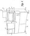
- Analyzer 50 includes a housing 60 built over an internal frame structure 62, preferably made of steel.
- the analyzer 50 is preferably supported on caster wheels 64 structurally mounted to the frame structure 62 so as to make the analyzer movable.
- housing 60 The various stations involved in performing an automated assay and the assay specimens are housed within housing 60.
- the various solutions, reagents, and other materials used in performing the assays are preferably stored within the housing 60, as are the waste products generated when assays are performed with the analyzer 50.
- Housing 60 includes a test receptacle loading opening 68, which is shown in FIGURE 1 to be disposed in a forwardly facing panel of the housing 60, but could as well be located in other panels of the housing 60.
- a pipette door 70 having a view window 72 and a carousel door 74 having a view window 76 are disposed above a generally horizontal work surface 66.
- a forwardly protruding arcuate panel 78 accommodates a specimen carousel, which will be described below.
- a flip-up arcuate specimen door 80 is pivotally attached to the housing so as to be vertically pivotal with respect to arcuate panel 78 so as to provide access to a forward portion of the specimen carousel behind the panel 78.
- the locking mechanism for each door preferably consists of a hook attached to a DC rotary solenoid (rated for continuous duty) with a spring return.
- Preferred rotary solenoids are available from Lucas Control Systems, of Vandalia, Ohio, model numbers L-2670-034 and L-1094-034.
- An extension portion 102 preferably made of a transparent or translucent material, extends above the top portion of housing 60 so as to provide vertical clearance for moving components within the housing 60.
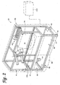
- the assays are performed primarily on a processing deck 200, which is the general location of the various assay stations of the analyzer 50 described below.
- the processing deck 200 is shown in FIGURE 2 without any of the assay stations mounted thereon.
- the processing deck 200 comprises a datum plate 82 to which the various stations are directly or indirectly mounted.
- Datum plate 82 preferably comprises a machined aluminum plate.
- the processing deck 200 also known as the chemistry deck, separates the interior of the housing into the chemistry area, or upper chassis, above the datum plate 82 and the storage areas, or lower chassis 1100, located below the datum plate 82.
- a number of fans and louvers are preferably provided in the upper chassis portion of the housing 60 to create air circulation throughout the upper chassis to avoid excessive temperatures in the upper chassis.
- the analyzer 50 includes a computer controller, schematically represented as box 1000 in FIGURE 2, which runs high-level analyzer-controlling software known as the "assay manager program".
- the assay manager program includes a scheduler routine which monitors and controls test specimen movement through the chemistry deck 200.
- the computer system 1000 which controls the analyzer 50 may include a stand-alone computer system including a CPU, keyboard, monitor, and may optionally include a printer device.
- a portable cart may also be provided for storing and supporting the various computer components.
- the computer hardware for running the analyzer-controlling software may be integrally housed within the housing 60 of the analyzer 50.
- Low level analyzer control such as control of electric motors and heaters used throughout the analyzer 50 and monitoring of fluid levels within bulk fluid and waste fluid containers, is performed by an embedded controller, preferably comprising a Motorola 68332 microprocessor. Stepper motors used throughout the analyzer are also preferably controlled by preprogrammed, off-the-shelf, microprocessor chips available from E-M Technologies, Bala Cynwyd, Pennsylvania.
- FIGURE 3 represents a schematic plan view of a poriton of the processing deck 200
- FIGURE 4 represents a schematic perspective view of the processing deck.
- the datum plate 82 forms the foundation of the processing deck 200 on which all stations are directly or indirectly attached.
- Processing deck 200 includes a reaction receptacle input queue 150 which extends from opening 68 in front of housing 60.
- a plurality of reaction receptacles are loaded in a stacked fashion in the input queue 150.
- the purpose of the input queue is to hold a prescribed number of reaction receptacles and to sequentially present them at a pick-up position to be retrieved by a transport mechanism (described below).
- a reflective sensor at the pick-up position verifies the presence of a receptacle at that position.
- the input queue also includes a device for counting the number of receptacles resident therein at any given time.
- a reaction receptacle shuttle assembly within the queue moves the receptacles along a receptacle advance path toward the pick-up position.
- Optical sensors indicate when the shuttle assembly is in its home and fully extended positions.
- the queue includes a drawer which may be pulled out for loading the receptacles therein. Before the drawer is opened, however, it must be unlocked and the shuttle must disengage from the receptacle advance path. When the drawer is again closed, it is locked and the shuttle engages the receptacles and moves them toward the pick-up position.
- Optical sensors indicate when the drawer is closed and when the shuttle has engaged a receptacle. As each receptacle is removed from the pick-up position by the transport mechanism, the receptacle shuttle advances the receptacles one receptacle-width, so that the next receptacle is in the pick-up position.
- reaction receptacles are preferably integrally formed linear arrays of test tubes and known as multi-tube units, or MTUs.
- MTUs multi-tube units
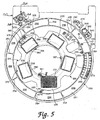
- a first ring assembly which in the preferred embodiment comprises a specimen ring 250, is mounted on a pivoting jig plate 130 at a distance above the datum plate 82.
- Specimen ring 250 is generally circular and preferably holds up to nine specimen trays 300 in an annular fluid container carrier portion thereof, and each of the specimen trays preferably holds 20 specimen-containing containers, or test tubes 320.
- the specimen ring 250 is constructed and arranged to be rotatable about a first generally vertical axis of rotation and delivers the specimen tubes 320 to a specimen pipette assembly 450, preferably an automated robotic pipette system.
- specimen ring 250 is accessible through the flip-up carousel door 80 provided in housing 60 so that trays 300 of test tubes 320 can be easily loaded onto the specimen ring 250 and unloaded from the specimen ring.
- Specimen ring 250 is driven by a motor, as will be described in more detail below.
- a second ring assembly which in the preferred embodiment comprises a pipette tip wheel 350, is located in an interior portion of the specimen ring 250, so that at least a portion of the outer perimeter of the pipette tip wheel 350 is disposed radially inwardly of the inner periphery of the ring 250.
- Pipette tip wheel 350 carries thereon a plurality of commercially available packages of pipette tips.
- Pipette tip wheel 350 is motor driven to rotate independently of specimen ring 250 about a second axis of rotation that is generally parallel to the first axis of rotation of the specimen ring 250.
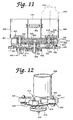
- the inner rotatable assembly constructed and arranged to carry a plurality of fluid containers is provided at an interior portion of the pipette tip wheel 350.
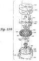
- the inner rotatable assembly comprises the multi-axis mixer 400 according to the present invention, located radially inside the pipette tip wheel 350 (i.e., the second ring assembly) and specimen ring 250 (i.e., the first ring assembly).
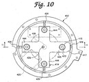
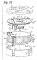
- the multi-axis mixer 400 includes a rotating turntable 414 that is rotatable about a third axis of rotation that is generally parallel to the first and second axes of rotation and on which are mounted four independently and eccentrically rotating container holders 406.
- Each of the container holders 406 receives a container, preferably in the form of a plastic bottle, containing a fluid suspension of magnetic particles with immobilized polynucleotides and polynucleotide capture probes.
- Each container holder 406 is generally cylindrical in shape and includes an axis of symmetry, or axis of rotation.
- the multi-axis mixer 400 rotates each of the containers eccentrically with respect to the center of the holder 406, while simultaneously rotating the turntable 414 about its center so as to provide substantially constant agitation of the containers to maintain the magnetic particles in suspension within the fluid.
- the specimen pipette assembly, or robot, 450 is mounted to the frame structure 62 (see FIGURE 2) in a position above the specimen ring 250 and pipette tip wheel 350.
- the specimen pipette assembly 450 includes a pipette unit 456 having a tubular probe 457 mounted on a gantry assembly to provide X, Y, Z motion.
- the pipette unit 456 is linearly movable in the Y-direction along a track 458 formed in a lateral rail 454, and the lateral rail 454 is longitudinally movable in the X-direction along a longitudinal track 452.
- the pipette unit 456 provides vertical, or Z-axis motion of the probe 457.
- Each axis of the specimen pipette assembly 450 is driven by a stepper motor in a known and conventional manner.
- the pipette assembly is preferably an off-the-shelf product.
- Presently preferred is the Robotic Sample Processor, model number RSP9000, available from Cavro Inc. of Sunnyvale, California. This model includes a single gantry arm.
- the specimen pipette assembly 450 is preferably coupled to a syringe pump (not shown) (the Cavro XP 3000 has been used) and a DC driven diaphragm system fluid wash pump (not shown).
- the syringe pump of the specimen pipette assembly 450 is preferably mounted to the internal frame structure 62 within the housing 60 of the analyzer 50 at a position above the left-hand side of the chemistry deck 200 and is connected to pipette unit 456 by suitable tubing (not shown) or other conduit structures.
- a specimen preparation opening 252 is provided in the jig plate 130, so that the specimen pipette assembly 450 can access a reaction receptacle 160 in the input queue 150 located below the jig plate 130.
- the specimen pipette assembly 450 of the analyzer 50 engages specimen tubes 320 carried on the specimen ring 250 through openings 140, 142 of an elevated cover plate 138 and engages pipette tips carried on the pipette tip wheel 350 near the back portions of the specimen ring 250 and pipette tip wheel 350, respectively. Accordingly, an operator can have access to the forward portions of specimen ring 250 and pipette tip wheel 350 through the carousel door opening, 80 during operation of the analyzer without interfering with pipetting procedures.
- a tip wash/disposal station 340 is disposed adjacent to the specimen ring 250 on the jig plate 130.
- Station 340 includes a tip disposal tube 342 and a wash station basin 346.
- the pipette unit 456 of the specimen pipette assembly 450 can move into position above the wash station basin 346 where the tubular probe 457 can be washed by pumping distilled water through the probe 457, the basin of the wash station 346 being connected, preferably by a flexible hose (not shown), to a liquid waste container in the lower chassis 1100.
- the tip disposal tube 342 comprises an upstanding tubular member.
- an elongated pipette tip is frictionally secured onto the end of the tubular probe 457 of the pipette unit 456, so that specimen material does not come into contact with the tubular probe 457 of the pipette unit 456 when material is drawn from a specimen tube 320 and into the elongated pipette tip.
- the pipette unit 456 moves to a position above the tip disposal tube 342 and ejects the used, disposable pipette tip into the tip disposal tube 342 which is connected to one of the solid waste containers carried in the lower chassis 1100.
- An elongated, pipette tip is preferably also frictionally secured to the probe 457 for transferring target capture reagent from containers carried on the multi-axis mixer 400 to a reaction receptacle 160. Following reagent transfer, the pipette tip is discarded.
- the specimen ring 250, the pipette tip wheel 350, and the multi-axis mixer 400 are preferably mounted on a hinged jig plate 130 (see FIGURES 5 and 6) supported above the datum plate 82.
- the jig plate 130 is hinged at a back end 132 thereof (see FIGURE 6) so that the plate, and the ring 250, the wheel 350, and the mixer 400 mounted thereon, can be pivoted upwardly to permit access to the area of the chemistry deck below the jig plate.
- a first, or right-side, transport mechanism 500 is mounted on the datum plate 82 below the jig plate 130 and specimen ring 250 on generally the same plane as the input queue 150.
- Transport mechanism 500 includes a rotating main body portion 504 defining a receptacle carrier assembly and an extendible manipulating hook 506 mounted within the main body 504 and extendible and retractable with respect thereto by means of a powered hook member drive assembly.
- Each of the reaction receptacles 160 preferably includes manipulating structure that can be engaged by the extendible manipulating hook 506, so that the transport mechanism 500 can engage and manipulate a reaction receptacle 160 and move it from one location on the processing deck 200 to another as the reaction receptacle is sequentially moved from one station to another during the performance of an assay within the reaction receptacle 160.
- a second, or left-side, transport mechanism 502, of substantially identical construction as first distribution arm 500, is also included on the processing deck 200.
- a plurality of receptacle parking stations 210 are also located below the jig plate 130.
- the parking stations 210 are structures for holding specimen-containing reaction receptacles until the assay performing stations of the processing deck 200 of the analyzer 50 are ready to accept the reaction receptacles.
- the reaction receptacles are retrieved from and inserted into the parking stations 210 as necessary by the transport mechanism 500.
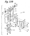
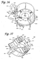
- a right-side orbital mixer 550 is attached to the datum plate 82 and receives reaction receptacles 160 inserted therein by the right-side transport mechanism 500.
- the orbital mixer is provided to mix the contents of the reaction receptacle 160.
- the right-side transport mechanism 500 removes the reaction receptacle from the right-side orbital mixer 550 and moves it to another location in the processing deck.
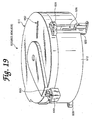
- incubators 600, 602, 604, 606, of substantially identical construction are provided.
- Incubators 600, 602, 604, and 606 are preferably rotary incubators. Although the particular assay to be performed and the desired throughput will determine the desired number of necessary incubators, four incubators are preferably provided in the analyzer 50.
- each incubator has a first, and may also have a second, receptacle access opening through which a transport mechanism 500 or 502 can insert a reaction receptacle 160 into the incubator or retrieve a reaction receptacle 160 from the incubator.
- a rotating receptacle carrier carousel which holds a plurality of reaction receptacles 160 within individual receptacle stations while the receptacles are being incubated.
- first rotary incubator 600 is a target capture and annealing incubator
- second rotary incubator 602 is an active temperature and pre-read cool-down incubator (also known as an "AT incubator")
- third rotary incubator 604 is an amplification incubator
- fourth rotary incubator 606 is a hybridization protection assay incubator.
- the construction, function, and role of the incubators in the overall performance of the assay will be described in more detail below.
- the processing deck 200 preferably also includes a plurality of temperature ramping stations 700. Two such stations 700 are shown attached to the datum plate 82 between incubators 602 and 604 in FIGURE 3. Additional ramping stations may be disposed at other locations on the processing deck 200 where they will be accessible by one of the transport mechanisms 500, 502.
- a reaction receptacle 160 may be placed into or removed from a temperature ramping station 700 by either transport mechanism 500 or 502. Each ramping station 700 either raises or lowers the temperature of the reaction receptacle and its contents to a desired temperature before the receptacle is placed into an incubator or another temperature sensitive station. By bringing the reaction receptacle and its contents to a desired temperature before inserting it into one of the incubators (600, 602, 604, 606), temperature fluctuations within the incubator are minimized.
- the processing deck 200 also includes magnetic separation wash stations 800 for performing a magnetic separation wash procedure.
- Each magnetic separation wash station 800 can accommodate and perform a wash procedure on one reaction receptacle 160 at a time. Therefore, to achieve the desired throughput, five magnetic separation wash stations 800 working in parallel are preferred.
- Receptacles 160 are inserted into and removed from the magnetic separation wash stations 800 by the left-side transport mechanism 502.
- a reagent cooling bay 900 is attached to the datum plate 82 roughly between the incubators 604 and 606.
- Reagent cooling bay 900 comprises a carousel structure having a plurality of container receptacles for holding bottles of temperature sensitive reagents.
- the carousel resides within a cooled housing structure having a lid with pipette-access holes formed therein.
- the left-side orbital mixer 552 includes dispenser nozzles and lines for dispensing fluids into the reaction receptacle resident within the left-side orbital mixer 552.
- a reagent pipette assembly, or robot, 470 includes a double gantry structure attached to the frame structure 62 (see FIGURE 2) and is disposed generally above the incubators 604 and 606 on the left-hand side of the processing deck 200.
- reagent pipette assembly 470 includes pipette units 480 and 482.
- Pipette unit 480 includes a tubular probe 481 and is mounted for linear movement, generally in the X-direction, along track 474 of lateral rail 476, and pipette unit 482, including a tubular probe 483, is also mounted for linear motion, generally in the X-direction, along track 484 of lateral rail 478.
- Each pipette unit 480, 482 provides independent vertical, or Z-axis, motion of the respective probe 481, 483.
- Drive mechanisms within the assembly 470 position the pipette units 480, 482 to the correct X, Y, Z coordinates within the analyzer 50 to pipette fluids, to wash the tubular probes 481, 483 of the respective pipette units 480, 482, or to stow the pipette units 480, 482 during periods of nonuse, e.g., in "home" positions.
- Each axis of the pipette assembly 470 is driven by a stepper motor.
- the reagent pipette assembly 470 is preferably an off-the-shelf product.
- the presently preferred unit is the Cavro Robotic Sample Processor, model RSP9000, with two gantry arms.
- the pipette units 480, 482 of the reagent pipette assembly 470 are each preferably coupled to a respective syringe pump (not shown) (the Cavro XP 3000 has been used) and a DC driven diaphragm system fluid wash pump.
- the syringe pumps of the reagent pipette assembly 470 are preferably mounted to the internal frame structure 62 within the housing 60 of the analyzer 50 at a position above the left-hand side of the chemistry deck 200 and are connected to the respective pipette units 480, 482 by suitable tubing (not shown) or other conduit structures.
- Each pipette unit 480, 482 preferably includes capacitive level sensing capability.
- Capacitive level sensing which is generally known in the medical instrumentation arts, employs capacitance changes when the dielectric of a capacitor, formed by the pipette unit as one plate of the capacitor and the structure and hardware surrounding a container engaged by the pipette unit as the opposite plate, changes from air to fluid to sense when the probe of the pipette unit has penetrated fluid within a container.
- the vertical position of the probe of the pipette unit which may be known by monitoring the stepper motor which drives vertical movement of the pipette unit, the level of the fluid within the container engaged by the pipette unit may be determined.
- Pipette unit 480 transfers reagents from the reagent cooling bay 900 into reaction receptacles disposed within the incubator 606 or the orbital mixer 552, and pipette unit 482 transfers reagent materials from the reagent cooling bay 900 into reaction receptacles disposed within the amplification incubator 604 or the orbital mixer 552.
- the pipette units 480, 482 use capacitive level sensing to ascertain fluid level within a container and submerge only a small portion of the end of the probe of the pipette unit to pipette fluid from the container.
- Pipette units 480, 482 preferably descend as fluid is pipetted into the respective tubular probes 481, 483 to keep the end of the probes submerged to a constant depth.
- the pipette units create a minimum travel air gap of 10 ⁇ l in the end of the respective probe 481 or 483 to ensure no drips from the end of the probe as the pipette unit is moved to another location above the chemistry deck 200.
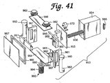
- the processing deck 200 includes a luminometer 950 for detecting and/or quantifying the amount of light emitted by the contents of the reaction receptacle.
- the luminometer 950 comprises a housing through which a reaction receptacle travels under the influence of a transport mechanism, a photomultiplier tube, and associated electronics. Various luminometer embodiments will be described in detail below.
- the processing deck 200 also preferably includes a deactivation queue 750.
- the assay performed in the analyzer 50 involves the isolation and amplification of nucleic acids belonging to at least one organism or cell of interest. Therefore, it is desirable to deactivate the contents of the reaction receptacle 160, typically by dispensing a bleach-based reagent into the reaction receptacle 160 at the conclusion of the assay. This deactivation occurs within the deactivation queue 750.
- reaction receptacle 160 Following deactivation, the deactivated contents of the reaction receptacle 160 are stored in one of the liquid waste containers of the lower chassis 1100 and the used reaction receptacle is discarded into a dedicated solid waste container within the lower chassis 1100.
- the reaction receptacle is preferably not reused.
- the analyzer 50 is initially configured for an assay run by loading bulk fluids into the bulk fluid storage bay of the lower chassis 1100 and connecting the bulk fluid containers to the appropriate hoses (not shown).
- the analyzer is preferably powered up in a sequential process, initially powering the stations, or modules, that will be needed early in the process, and subsequently powering the stations that will not be needed until later in the process. This serves to conserve energy and also avoids large power surges that would accompany full analyzer power-up and which could trip circuit breakers.
- the analyzer also employs a "sleep" mode during periods of nonuse. During sleep mode, a minimal amount of power is supplied to the analyzer, again to avoid large surges necessary to power-up an analyzer from complete shut-down.
- reaction receptacles 160 preferably in the form of plastic, integrally formed multiple-tube units (MTUs), which are described in more detail below, are loaded through opening 68 into the input queue 150.
- MTUs multiple-tube units
- the reaction receptacle shuttle assembly (not shown) within the input queue 150 moves the MTUs 160 from the loading opening 68 to the pick-up position at the end of the queue 150.
- the right-side transport mechanism 500 takes an MTU 160 from the end of the queue 150 and moves it to a bar code reader 253 to read the unique bar code label on that MTU which identifies that MTU. From the bar code reader 253, the MTU is moved to an available specimen transfer station 255 below opening 252.
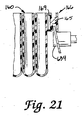
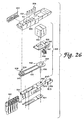
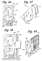
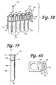
- an MTU 160 comprises a plurality of individual receptacle vessels 162, preferably five.
- the receptacle vessels 162, preferably in the form of cylindrical tubes with open top ends and closed bottom ends, are connected to one another by a connecting rib structure 164 which defines a downwardly facing shoulder extending longitudinally along either side of the MTU 160.
- the MTU 160 is preferably formed from injection molded polypropylene.
- the most preferred polypropylene is sold by Montell Polyolefins, of Wilmington, Delaware, product number PD701NW.
- the Montell material is used because it is readily moldable, chemically compatible with the preferred mode of operation of the analyzer 50, and has a limited number of static discharge events which can interfere with accurate detection or quantification of chemiluminescence.
- An arcuate shield structure 169 is provided at one end of the MTU 160.
- An MTU manipulating structure 166 to be engaged by one of the transport mechanisms 500, 502 extends from the shield structure 169.
- MTU manipulating structure 166 comprises a laterally extending plate 168 extending from shield structure 169 with a vertically extending piece 167 on the opposite end of the plate 168.
- a gusset wall 165 extends downwardly from lateral plate 168 between shield structure 169 and vertical piece 167.
- the shield structure 169 and vertical piece 167 have mutually facing convex surfaces.
- the MTU 160 is engaged by the transport mechanisms 500, 502 and other components, as will be described below, by moving an engaging member laterally (in the direction "A")into the space between the shield structure 169 and the vertical piece 167.
- the convex surfaces of the shield structure 169 and vertical piece 167 provide for wider points of entry for an engaging member undergoing a lateral relative motion into the space.
- the convex surfaces of the vertical piece 167 and shield structure 169 include raised portions 171, 172, respectively, formed at central portions thereof. The purpose of portions 171, 172 will be described below.
- a label-receiving structure 174 having a flat label-receiving surface 175 is provided on an end of the MTU 160 opposite the shield structure 169 and MTU manipulating structure 166. Labels, such as scannable bar codes, can be placed on the surface 175 to provide identifying and instructional information on the MTU 160.
- the MTU 160 preferably includes tiplet holding structures 176 adjacent the open mouth of each respective receptacle vessel 162.
- Each tiplet holding structure 176 provides a cylindrical orifice within which is received a contact-limiting tiplet 170.
- the construction and function of the tiplet 170 will be described below.
- Each holding structure 176 is constructed and arranged to frictionally receive a tiplet 170 in a manner that prevents the tiplet 170 from falling out of the holding structure 176 when the MTU 160 is inverted, but permits the tiplet 170 to be removed from the holding structure 176 when engaged by a pipette.
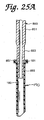
- the tiplet 170 comprises a generally cylindrical structure having a peripheral rim flange 177 and an upper collar 178 of generally larger diameter than a lower portion 179 of the tiplet 170.
- the tiplet 170 is preferably formed from conductive polypropylene.
- Hole 180 includes an outwardly flared end 181 at the top of the tiplet 170 which facilitates insertion of a pipette tubular probe (not shown) into the tiplet 170.
- Two annular ridges 183 line the inner wall of hole 180. Ridges 183 provide an interference friction fit between the tiplet 170 and a tubular probe inserted into the tiplet 170.
- the bottom end of the tiplet 170 preferably includes a beveled portion 182.
- a reaction receptacle such as a receptacle vessel 162 of an MTU 160
- the beveled portion 182 prevents a vacuum from forming between the end of the tiplet 170 and the bottom of the reaction receptacle vessel.
- the lower chassis 1100 includes a steel frame 1101 with a black polyurethane powder coat, a pull-out drip tray 1102 disposed below the chassis, a right-side drawer 1104, and a left-side drawer 1106.
- the left-side drawer 1106 is actually centrally disposed within the lower chassis 1100.
- the far left-side of the lower chassis 1100 houses various power supply system components and other analyzer mechanisms such as, for example, seven syringe pumps 1152 mounted on a mounting platform 1154, a vacuum pump 1162 preferably mounted on the floor of the lower chassis 1100 on vibration isolators (not shown), a power supply unit 1156, a power filter 1158, and fans 1160.
- a different syringe pump 1152 is designated for each of the five magnetic separation wash stations 800, one is designated for the left-side orbital mixer 552, and one is designated for the deactivation queue 750. Although syringe pumps are preferred, peristaltic pumps may be used as an alternative.
- the vacuum pump 1162 services each of the magnetic separation wash stations 800 and the deactivation queue 750.
- the preferred rating of the vacuum pump is 5.3-6.5 cfm at 0" Hg and 4.2-5.2 cfm at 5" Hg.
- a preferred vacuum pump is available from Thomas Industries, Inc. of Sheboygan, Wisconsin, as model number 2750CGH160.
- a capacitor 1172 is sold in conjunction with the pump 1162..
- the power supply unit 1156 is preferably an ASTEC, model number VS1-B5-B7-03, available from ASTEC America, Inc., of Carlsbad, California. Power supply unit 1156 accepts 220 volts ranging from 50-60 Hz, i.e.,power from a typical 220 volt wall outlet. Power filter 1158 is preferably a Corcom model 20MV1 filter, available from Corcom, Inc: of Libertyville, Illinois. Fans 1160 are preferably Whisper XLDC fans available from Comair Rotron, of San Ysidro, California. Each fan is powered by a 24VDC motor and has a 75 cfm output.
- the fans 1160 are preferably disposed proximate a left-side outer wall of the lower chassis 1100.
- the fans 1160 are preferably directed outwardly to draw air through the lower chassis from the right-side thereof to the left-side thereof, and thus, to draw excess heat out of the lower chassis.
- a power switch 1174 preferably an Eaton circuit breaker switch 2-pole, series JA/S, available from the Cutler-Harnmer Division of Eaton Corporation of Cleveland, Ohio, and a power inlet module 1176 at which a power cord (not shown) for connecting the analyzer 50 to an external power source is connected.
- a power switch 1174 preferably an Eaton circuit breaker switch 2-pole, series JA/S, available from the Cutler-Harnmer Division of Eaton Corporation of Cleveland, Ohio
- a power inlet module 1176 at which a power cord (not shown) for connecting the analyzer 50 to an external power source is connected.
- the power supply system of the analyzer 50 also includes a terminal block (not shown), for attaching thereto a plurality of electrical terminals, a solid state switch (not shown), which is preferably a Crydom Series 1, model number D2425, available from Cal Switch, Carson City, California, for switching between different circuits, and an RS232 9-pin connector port for connecting the analyzer 50 to the external computer controller 1000.
- a terminal block for attaching thereto a plurality of electrical terminals
- a solid state switch (not shown), which is preferably a Crydom Series 1, model number D2425, available from Cal Switch, Carson City, California, for switching between different circuits
- an RS232 9-pin connector port for connecting the analyzer 50 to the external computer controller 1000.
- the right-side drawer and left-side drawer bays are preferably closed behind one or two doors (not shown) in front of the analyzer, which is/are preferably locked by the assay manager program during operation of the analyzer. Microswitches are preferably provided to verify door-closed status.
- the far left bay is covered by a front panel. End panels are provided on opposite ends of the lower chassis to enclose the chassis.
- leveler feet 1180 extend down from the four corners of the chassis 1100.
- the leveler feet 1180 include threaded shafts with pads at the lower ends thereof. When the analyzer is in a desired location, the feet 1180 can be lowered until the pads engage the floor to level and stabilize the analyzer. The feet can also be raised to permit the analyzer to be moved on its casters.
- Bulk fluids typically contained in the containers of the lower chassis 1100 may include wash buffer (for washing' immobilized target), distilled water (for washing fixed pipette tips), diagnostic testing reagents, silicon oil (used as a floating fluid for layering over test reagents and specimen), and a bleach-based reagent (used for sample deactivation).
- wash buffer for washing' immobilized target
- distilled water for washing fixed pipette tips
- diagnostic testing reagents for washing fixed pipette tips
- silicon oil used as a floating fluid for layering over test reagents and specimen
- a bleach-based reagent used for sample deactivation
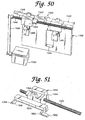
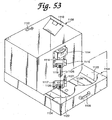
- the right-side drawer 1104 is shown in detail in FIGURE 53.
- the right-side drawer 1104 includes a box-like drawer structure with a front drawer handle 1105.
- drawer handle 1105 is shown as a conventional pull-type drawer handle, in the preferred embodiment of the analyzer 50, handle 1105 is a T-handle latch, such as those available from Southco, Inc. of Concordville, Pennsylvania.
- the drawer 1104 is mounted in the lower chassis on slide brackets (not shown) so that the drawer 1104 can be pulled into and out of the lower chassis.
- a sensor (not shown) is preferably provided for verifying that the drawer 1104 is closed.
- the front portion of the drawer includes bottle receptacles 1122 for holding bottle 1128 (shown in FIGURE 52), which is a dedicated pipette wash waste-containing bottle, and bottle 1130 (also shown in FIGURE 52), which is a dedicated waste bottle for containing waste from a magnetic wash, target-capture procedure.
- Bottle 1130 is preferably evacuated.
- Bottle receptacles 1122 preferably include bottle-present sensors (not shown) to verify the presence of a bottle in each receptacle 1122.
- the bottle-present sensors are preferably diffuse reflective type optical sensors available from SUNX/Ramco Electric, Inc., of West Des Moines, Iowa, model EX-14A.
- Right-side drawer 1104 further includes a waste bin 1108 for holding therein spent MTUs and specimen tips.
- Waste bin 1108 is an open box structure with a sensor mount 1112 at a top portion thereof for mounting thereon a sensor, preferably a 24VDC Opto-diffuse reflector switch (not shown), for detecting whether the waste bin 1108 is full.
- Another diffuse reflector type optical sensor (not shown) is positioned within right-side drawer 1104 to verify that the waste bin 1108 is in place.
- diffuse reflective type optical sensors available from SUNX/Ramco Electric, Inc., of West Des Moines, Iowa, model EX-14A, are preferred.
- a deflector 1110 extends obliquely from a side of the waste bin 1108.
- Deflector 1110 is disposed directly below a chute through which spent MTUs are dropped into the waste bin 1108 and deflects the dropped MTUs toward the middle of the waste bin 1108 to avoid MTU pile-ups in a corner of the waste bin 1108.
- Deflector 1110 is preferably pivotally mounted so that it can pivot upwardly to a substantially vertical position so that when a waste bag, which lines the waste bin 1108 and covers the deflector 1110, is removed from the waste bin 1108, the deflector 1110 will pivot upwardly with the bag as it is pulled out and therefore will not rip the bag.
- a printed circuit board (not shown) and cover 1114 can be mounted to the front of the waste bin 1108.
- Sensor mounts 1116 and 1117 are also mounted to the front of waste bin 1108.
- Sensors 1118 and 1119 are mounted on sensor mount 1116, and sensors 1120 and 1121 mounted on sensor mount 1117.
- Sensors 1118, 1119, 1120, and 1121 are preferably DC capacitive proximity sensors.
- the upper sensors 1118, 1119 indicate when the bottles 1128 and 1130 are full, and the bottom sensors 1120, 1121 indicate when the bottles are empty.
- Sensors 1118-1121 are preferably those available from Stedham Electronics Corporation of Reno, Nevada, model number C2D45AN1-P, which were chosen because their relatively flat physical profile requires less space within the tight confines of the lower chassis 1100 and because the Stedham sensors provide the desired sensing distance range of 3-20 mm.
- the analyzer 50 will preferably not begin performing any assays if the assay manager program detects that any of the waste fluid containers in the right-side drawer 1104 are not initially empty.
- the capacitive proximity sensors 1118-1121 and the bottle-present, waste-bin-present, and waste-bin-full optical sensors of the right-side drawer 1104 are connected to the printed circuit board (not shown) behind cover 1114, and the printed circuit board is connected to the embedded controller of the analyzer 50.
- a handle 1126 is mounted to the front of the waste bin 1108 and teflon strips 1124 are disposed on the bottom floor of the right-side drawer 1104 to facilitate forward and backward sliding of the waste bin 1108 in the drawer 1104 when bottles 1128 and 1130 are removed.
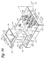
- Left-side drawer 1106 includes a box-like structure with a front mounted handle 1107 and is mounted within the lower chassis 1100 on slide brackets (not shown).
- handle 1107 is shown as a conventional pull-type drawer handle, in the preferred embodiment of the analyzer 50, handle 1107 is a T-handle latch, such as those available from Southco, Inc. of Concordville, Pennsylvania.
- a sensor is provided for verifying that the left-side drawer 1106 is closed.
- Left-side drawer 1106 includes a tiplet waste bin 1134 with a mounting structure 1135 for mounting thereon a tiplet-waste-bin-full sensor (not shown).
- a tiplet-waste-bin-present sensor is preferably provided in the left-side drawer 1106 to verify that the tiplet waste bin 1134 is properly installed.
- Diffuse reflective type optical sensors available from SUNX/Ramco Electric, Inc., of West Des Moines, Iowa, model EX-14A, are preferred for both the tiplet-waste-bin-full sensor and the tiplet-waste bin-present sensor.
- Bundling structures 1132 are provided for securing and bundling various tubing and/or wires (not shown) within the lower chassis 1100.
- the bundling structures preferably used are Energy Chain Systems manufactured and sold by Igus, Inc. of East Buffalo, Rhode Island.
- a printed circuit board 1182 is mounted behind a panel 1184 which is located behind the tiplet waste bin 1134.
- a solenoid valve mounting panel 1186 is located below the tiplet waste bin 1134.
- Left-side drawer 1106 includes a forward container-holding structure for holding therein six similarly sized bottles.
- the container structure includes divider walls 1153, 1155, 1157, and 1159 and container blocks 1151 having a curved bottle-conforming front edge, which together define six container-holding areas.
- Lower sensors 1148 and upper sensors 1150 (six of each) are mounted on the divider walls 1155, 1157, and 1159.
- the upper and lower sensors 1148, 1150 are preferably DC capacitive proximity sensors (preferably sensors available from Stedham Electronics Corporation of Reno, Nevada, model number C2D45ANI-P, chosen for their flat profile and sensing range).
- the upper sensors 1150 indicate when the bottles held in the container structure are full, and the lower sensors 1148 indicate when the bottles are empty.
- the left two bottles 1146 contain a detecting agent ("Detect I")
- the middle two bottles 1168 contain silicon oil
- the right two bottles 1170 contain another detecting agent
- Bottle-present sensors are preferably provided in each of the container-holding areas defined by the container blocks 1151 and the dividing walls 1153, 1155, 1157, and 1159 to verify the presence of bottles in each container-holding area.
- the bottle-present sensors are preferably diffuse reflective type optical sensors available from SUNX/Ramco Electric, Inc., of West Des Moines, Iowa, model EX-14A.
- a large centrally located container receptacle 1164 holds a bottle 1140 (shown in FIGURE 52), preferably containing deionized water.
- Container receptacles 1166 (only one is visible in FIGURE 54) hold bottles 1142 and 1144 (also shown in FIGURE 52) preferably containing a wash buffer solution.
- a dividing wall 1143 between the receptacle 1164 and 1166 has mounted thereon sensors, such as sensor 1141, for monitoring the fluid level in the bottles 1140, 1142, and 1144.
- the sensors, such as sensor 1141 are preferably DC capacitive proximity sensors (preferably sensors available from Stedham Electronics Corporation of Reno, Nevada, model number C2D45AN1-P).
- Container receptacles 1164 and 1166 preferably include bottle-present sensors (not shown) for verifying that bottles are properly positioned in their respective receptacles.
- the bottle-present sensors are preferably diffuse reflective type optical sensors available from SUNX/Ramco Electric, Inc., of West Des Moines, Iowa, model EX-14A.
- the analyzer 50 will not begin performing any assays if the assay manager program determines that any of the bulk-fluid containers in the left-side drawer 1106 are initially empty.
- the capacitive proximity fluid level sensors, the various bottle-present sensors, the tiplet-waste-bin-full sensor, and the tiplet-waste-bin-present sensors are all connected to the printed circuit board 1182, and the printed circuit board 1182 is connected to the embedded controller of the analyzer 50.
- solenoid valves (not shown) are mounted below the solenoid valve mounting panel 1186.
- the solenoid valves connect bulk fluid bottles where fluids are stored in pairs of bottles, i.e., the bottles 1140, 1142 containing wash buffer solution, the two bottles 1146 containing the "Detect I” agent, the two bottles 1168 containing oil, and the two bottles 1170 containing the "Detect II” agent.
- the solenoid valves in response to signals from the respective capacitive proximity sensors, switch bottles from which fluid is being drawing when one of the two bottles containing the same fluid is empty.
- the solenoid valves may switch bottles after a prescribed number of tests are performed.
- the preferred solenoid valves are teflon solenoid valves available from Beco Manufacturing Co., Inc. of Madison Hills, California, model numbers S313W2DFRT and M223W2DFRLT. The two different model numbers correspond to solenoid valves adapted for use with two different tube sizes. Teflon solenoid valves are preferred because they are less likely to contaminate fluids flowing through the valves and the valves are not damaged by corrosive fluids flowing through them.
- Bottle 1136 (see FIGURE 52) is a vacuum trap held in a vacuum trap bracket 1137, and bottle 1138 contains a deactivating agent, such as bleach-containing reagent.
- a deactivating agent such as bleach-containing reagent.
- bottle-present sensors are preferably provided to verify the presence of bottles 1136 and 1138.
- a hand-held bar code scanner 1190 may be provided in the lower chassis 1100 for scanning information provided on scannable container labels into the assay manager program.
- Scanner 1190 is connected by a cord to printed circuit board 1182 of the left-side drawer 1106 and is preferably stowed on a bracket (not show) mounted on dividing wall 1143.
- Scanners available from Symbol Technologies, Inc., of Holtsville, New York, series LS2100, are preferred.
- Specimens are contained in the specimen tubes 320, and the tubes 320 are loaded into the tube trays 300 outside the analyzer 50.
- the trays 300 carrying the specimen tubes 320 are placed onto the specimen ring 250 through the access opening provided by opening the flip-up carousel door 80.
- the first ring assembly, or specimen ring, 250 is formed of milled, unhardened aluminum and includes a raised ring structure defining an annular trough 251 about the outer periphery of ring 250 with a plurality of raised, radially extending dividers 254 extending through trough 251.
- nine dividers 254 divide the trough 251 into nine arcuate specimen tube tray-receiving wells 256.
- the trough 251 and wells 256 define an annular fluid container carrier portion constructed and arranged to carry a plurality of containers as will be described below.
- Specimen ring 250 is preferably rotationally supported by three 120°-spaced V-groove rollers 257, 258, 260 -which engage a continuous V-ridge 262 formed on the inner periphery of ring 250, as shown in FIGURES 5 and 6, so that the ring 250 is rotatable about a first central axis of rotation.
- the rollers are preferably made by Bishop-Wisecarver Corp. of Pittsburg, California, model number W1SSX.
- Rollers 257 and 260 are rotationally mounted on fixed shafts, and roller 258 is mounted on a bracket which pivots about a vertical axis and is spring biased so as to urge roller 258 radially outward against the inner periphery of ring 250.
- ring 250 can be easily installed and removed by merely pushing pivoting roller 258 radially inwardly to allow the specimen ring 250 to move laterally to disengage continuous V-ridge 262 from the fixed V-groove rollers 257, 260.
- Specimen ring 250 is driven by stepper motor 264 (VEXTA stepper motors available from Oriental Motor Co., Ltd. of Tokyo, Japan as model number PK266-01A are preferred) via continuous belt 270 (preferably available from SDP/SI of New Hyde Park, New York, as model number A6R3M444080) which extends over guide rollers 266, 268 and around the outer periphery of ring 250.
- a home sensor and a sector sensor (not shown), preferably slotted optical sensors, are provided adjacent the ring 250 at a rotational home position and at a position corresponding to one of the specimen tube tray receiving wells 256.
- the ring 250 includes a home flag (not shown) located at a home position on the wheel and nine equally-spaced sector flags (not shown) corresponding to the positions of each of the nine specimen tube tray receiving wells 256.
- the home flag and sector flags cooperate with the home sensor and sector sensors to provide ring position information to the assay manager program and to control the ring 250 to stop at nine discrete positions corresponding to established coordinates for user re-load and access by pipette unit 450.
- Preferred sensors for the home sensor and sector sensor are Optek slotted optical sensors, model number OPB857, available from Optek of Carrollton, Texas.
- a specimen cover is disposed over a portion of the annular fluid container carrier portion, or trough 251, and comprises an arcuate cover plate 138 fixed in an elevated position with respect to the wheel 250 on three mounting posts 136.
- Plate 138 has an arcuate shape generally conforming to the curve of the trough 251.
- a first opening 142 is formed in the plate 138, and a second opening 140 is formed in the plate 138 at a greater radial distance from the axis of rotation of ring 250 than opening 142 and at a circumferentially-spaced position from opening 142.
- each specimen tube tray 300 comprises a test tube rack structure that is curved to conform to the curvature of the ring 250.
- Each tray 300 comprises a central wall structure 304 with lateral end walls 303 and 305 disposed on either end of wall 304.
- a floor 312 extends across the bottom of the tray 300.
- the principle purposes of specimen tube tray 300 are to hold specimen tubes on the specimen ring 250 for access by the specimen pipette assembly 450 and to facilitate loading and unloading of multiple specimen tubes into and from the analyzer.
- a plurality of Y-shaped dividers 302 are equidistantly spaced along opposite edges of the tray 300. Each two adjacent dividers 302 define a test-tube receiving area 330.
- End wall 303 includes inwardly bent flanges 316 and 318, and end wall 305 includes inwardly bent flanges 326 and 328.
- the respective inwardly bent flanges of end walls 303 and 305 along with the end-most of the dividers 302 define the end-most tube receiving areas 332.
- the receiving areas 330, 332 are arcuately aligned along two arcuate rows on opposite sides of central wall structure 304
- a leaf spring element 310 is attached to central wall 304.
- Leaf spring element 310 preferably formed of stainless spring steel, elastically deflects when a test tube 320 is inserted into the tube-receiving area 330 or 332 and urges the tube 320 outwardly against the dividers 302.
- the shape of the dividers 302 and the elasticity of the leaf spring elements 310 allow the tray 300 to accommodate specimen tubes of various shapes and sizes, such as tubes 320 and 324.
- Each tray 300 preferably includes nine dividers 302 along each edge to form, along with end walls 303 and 305, ten tube-receiving areas 330, 332 on each side of central wall structure 304 for a total of twenty tube-receiving areas per tray.
- Indicia for designating tube-receiving areas 330 and 332, such as raised numerals 306, may be provided on the tray, such as on central wall 304.
- Each tray 300 may also include boss structures 308, shown in the illustrated embodiment to be integrally formed with the end-most dividers 302.
- An upright inverted U-shaped handle (not shown) may be attached to the tray at boss structures 308 or some other suitable location. Upright handles can facilitate handling of the tray 300 when loading and unloading the tray 300 through the arcuate carousel door 80, but are not necessarily preferred.
- a gap is provided between adjacent dividers 302 so that bar-code labels 334, or other readable or scannable information, on the tubes 320 is accessible when the tube is placed in the tray 320.
- a tray 300 carried on wheel 250 passes beneath the plate 138 of the specimen cover, one tube 320 in a curved row at a radially-inward position with respect to wall structure 304 will be aligned with first opening 142 and another tube 320 in a curved row at a radially-outward position with respect to wall 304 will be aligned with second opening 140.
- the ring 250 is indexed to sequentially move each tube 320 beneath the openings 140, 142 to permit access to the tubes.
- bar code scanners 272 and 274 are disposed adjacent the ring 250.
- Scanner 272 is located outside ring 250, and scanner 274 is disposed inside ring 250. Scanners 272 and 274 are positioned to scan bar code data labels on each specimen tube 320 carried in the specimen tube tray 300 as the ring 250 rotates a tray 300 of specimen tubes 320 past the scanners 272, 274.
- the scanners 272, 274 scan the bar code label 337 (see FIGURE 55) on the outer portion of bent flanges 316 and 318 of end wall 303 of each tray 300 as the tray 300 is brought into the specimen preparation area.
- Various information such as specimen and assay identification, can be placed on the tubes and/or each tray 300, and this information can be scanned by the scanners 272, 274 and stored in the central processing computer. If no specimen tube is present, the tray 300 presents a special code 335 (see FIGURE 55) to be read by the scanners 272, 274.
- a second ring assembly of the preferred embodiment is a pipette tip wheel 350 and comprises a circular ring 352 at a bottom portion thereof, a top panel 374 defining a circular inner periphery and five circumferentially-spaced, radially-protruding sections 370, and a plurality of generally rectangular risers 354 separating the top panel 374 from the ring 352 and preferably held in place by mechanical fasteners 356 extending through the top panel 374 and ring 352 into the risers 354.
- Five rectangular openings 358 are formed in the top panel 374 proximate each of the sections 370, and a rectangular box 376 is disposed beneath panel 374, one at each opening 358.
- Top panel 374, ring 352, and risers 354 are preferably made from machined aluminum, and boxes 376 are preferably formed from stainless steel sheet stock.
- the openings 358 and associated boxes 376 are constructed and arranged to receive trays 372 holding a plurality of disposable pipette tips.
- the pipette tip trays 372 are preferably those manufactured and sold by TECAN (TECAN U.S. Inc., Research Triangle Park, North Carolina) under the trade name "Disposable Tips for GENESIS Series". Each tip has a 1000 ⁇ l capacity and is conductive. Each tray holds ninety-six elongated disposable tips.
- Lateral slots 378 and longitudinal slots 380 are formed in the top panel 374 along the lateral and longitudinal edges, respectively, of each opening 358.
- the slots 378, 380 receive downwardly-extending flanges (not shown) disposed along the lateral and longitudinal edges of the trays 372.
- the slots 378, 380 and associated flanges of the trays 372 serve to properly register the trays 372 with respect to openings 358 and to hold the trays 372 in place on the panel 374.
- Pipette tip wheel 350 is preferably rotationally supported by three 120°-spaced V-groove rollers 357, 360, 361 which engage a continuous V-ridge 362 formed on the inner periphery of ring 352, as shown in FIGURES 5, 6, and 6A, so that the pipette tip wheel 350 is rotatable about a second central axis of rotation that is generally parallel to the first axis of rotation of the specimen ring 250.
- the rollers are preferably made by Bishop-Wisecarver Corp. of Pittsburg, California, model number W 1SSX.
- Rollers 357 and 360 are rotationally mounted on fixed shafts, and roller 361 is mounted on a bracket which pivots about a vertical axis and is spring biased so as to urge roller 361 radially outwardly against the inner periphery of ring 352.
- Having two fixed rollers and one radially movable roller allows the three rollers to accommodate an out-of-round inner periphery of ring 352.
- the wheel 350 can be easily installed and removed by merely pushing pivoting roller 361 radially inwardly to allow the ring 352 to move laterally to disengage continuous V-ridge 362 from the fixed V-groove rollers 357, 360.
- Pipette tip wheel 350 is driven by a motor 364 having a shaft-mounted spur gear which meshes with mating gear teeth formed on an outer perimeter of ring 352.
- Motor 364 is preferably a VEXTA gear head stepper motor, model number PK243-A1-SG7.2, having a 7.2:1 gear reduction and available from Oriental Motor Co., Ltd. of Tokyo, Japan.
- a gear head stepper motor with a 7.2:1 gear reduction is preferred because it provides smooth motion of the pipette tip wheel 350, where the spur gear of the motor 364 is directly engaged with the ring 352.
- a home sensor and a sector sensor are provided adjacent the pipette tip wheel 350 at a rotational home position and at a position of one of the boxes 376.
- the pipette tip wheel 350 includes a home flag (not shown) located at a home position on the wheel and five equally-spaced sector flags (not shown) corresponding to the positions of each of the five boxes 376.
- the home flag and sector flags cooperate with the home sensor and sector sensors to provide wheel position information to the assay manager program and to control the pipette tip wheel 350 to stop at five discrete positions corresponding to established coordinates for user re-load and access by pipette unit 450.
- Preferred sensors for the home sensor and sector sensor are Optek Technology, Inc. slotted optical sensors, model number OPB980, available from Optek Technology, Inc. of Carrollton, Texas.
- the multi-axis mixer 400 of the present invention includes a rotating turntable structure 414 (see FIGURE 10) rotatably mounted on a center shaft 428 supported in center bearings 430 to a fixed base 402 mounted to the jig plate 130 by means of mechanical fasteners (not shown) extending through apertures 419 formed about the outer periphery of the fixed base 402.
- a cover member 404 is attached to and rotates with turntable 414.
- Turntable 414 is preferably in the form of a right angle cross comprising three 90°-spaced rectangular arms 444 of equal length extending radially outwardly from the center of the turntable 414 and a fourth arm 445 having an extension 417 making arm 445 slightly longer than arms 444. As shown in FIGURES 10-12, the center portion of turntable 414 is connected to center shaft 428 by a screw 429.
- Each container holder 406 is disposed on the ends of the arms 444 and 445 of turntable frame 414. Each container holder 406 is attached to one of four vertical shafts 423, which are rotatably supported in container holder bearings 415. Container holder bearings 415 are pressed into the arms 444, 445 of the turntable 414 and are disposed at equal radial distances from shaft 428.
- the cover member 404 includes four circular openings with upwardly-turned peripheral flanges 401 through which shafts 423 extend. Upward flanges 401 can advantageously prevent spilled liquids from flowing into the openings.
- the container holders 406 comprise generally cylindrical members having an open bottom and an open top for receiving and holding a container 440, preferably a plastic bottle, of target capture reagent.
- the target capture reagent used with the preferred assay includes magnetically responsive particles with immobilized polynucleotides, polynucleotide capture probes, and reagents sufficient to lyse cells containing the targeted nucleic acids.
- targeted nucleic acids are available for hybridization under a first set of predetermined hybridization conditions with one or more capture probes, with each capture probe having a nucleotide base sequence region which is capable of hybridizing to a nucleotide base sequence region contained on at least one of the targeted nucleic acids.
- a homopolymer tail (e.g., oligo(dT)) of the immobilized polynucleotides is capable of hybridizing with a' complementary homopolymer tail (e.g., oligo(dA)) contained on the capture probe, thereby immobilizing targeted nucleic acids.
- a homopolymer tail e.g., oligo(dT)
- oligo(dA) oligo(dA)
- a container retainer spring 408 spans a lateral slot formed in the wall of each container holder 406 and helps to hold the container 440 within the container holder 406 by urging the container 440 toward a portion of the inner peripheral wall of the holder 406 opposite the spring 408.
- Each container holder 406 is secured to an associated vertical shaft 423 by a shaft block structure 432.
- Shaft block structure 432 includes curved end portions which conform to the inside of the cylindrical container holder 406, and the container holder 406 is secured to the block 432 by fasteners 434.
- a generally circular aperture 449 receives the shaft 423.
- a slot 438 extends from aperture 449 to an end of the block 432 which does not extend all the way to the inside of the container holder 406, and a second slot 436 extends from an edge of the block 432 generally perpendicularly to slot 438 so as to define a cantilevered arm 435.
- a machine screw 437 extends through a through-hole 441 formed laterally through block 432 and into a threaded hole 447 formed laterally through arm 435. As screw 437 is tightened, arm 435 deflects, thus tightening aperture 449 around shaft 423.
- the shaft block structure 432, the shaft 423, and the container holder bearings 415 associated with each container holder 406 define a preferred container holder mounting structure associated with each container holder 406 that is constructed and arranged to mount the container holder 406 to the turntable 414 and permit the container holder 406 to rotate about an axis of rotation 412 of the shaft 423.
- Container holder planetary gears 422 are attached to the opposite ends of shafts 423.
- the planetary gears 422 operatively engage a stationary sun gear 416.
- a drive pulley 418 is attached to center shaft 428 and is coupled to a drive motor 420 by a drive belt (not shown).
- Drive motor 420 is preferably mounted so as to extend through an opening (not shown) in the jig plate 130 below the base 402.
- Drive motor 420 is preferably a stepper motor, and most preferably a VEXTA. stepper motor, model number PK264-01A, available from Oriental Motor Co., Ltd. of Tokyo, Japan.
- the drive motor 420 via the drive belt and drive pulley 418, rotates the center shaft 428 and the turntable 414 attached thereto.
- each container holder 406 is preferably mounted such that the axis of rotation 410 thereof is offset from the axis of rotation 412 of the associated shaft 423. Thus, each container holder 406 rotates eccentrically about axis 412 of the associated shaft 423.
- the planetary gears 422 and the sun gear 416 constitute rotational motion coupling elements constructed and arranged to cause the container holders 406 to rotate about the respective axes of rotation of the shafts 423 as the turntable 414 rotates about the axis of rotation of the shaft 428.
- a bar code scanner device 405 is preferably mounted on a bracket 403 and reads bar code information of the containers 440 through a scanner slot 407 formed in each container holder 406.
- the preferred scanner is a model number NFT1125/002RL scanner, available from Opticon, Inc. of Orangeburg, New York.
- the multi-axis mixer 400 usually rotates during operation of the analyzer 50 to agitate the fluid contents of the containers 440 to thereby keep the target capture reagent in suspension, stopping only briefly to permit pipette unit 456 to withdraw an amount of mixture from one of the containers.
- Pipette unit 456 draws mixture from a bottle at the same location each time. Therefore, it is desirable to monitor the positions of the bottles so that the bottle from which mixture is withdrawn each time can be specified.
- optical slotted sensors 426 each comprising an optical emitter and detector, are stationed around the periphery of fixed base 402, spaced at 90° intervals.
- Optical sensors available from Optek Technology, Inc. of Carrollton, Texas, model number OPB490P11, are preferred.
- a sensor tab 424 extends down from extension 417 at the end of arm 445 of the turntable 414. When sensor tab 424 passes through a sensor 426, the communication between the emitter and detector is broken thus giving a "container present" signal.
- the tab 424 is only provided at one location, e.g., the first container location. By knowing the position of the first container, the positions of the remaining containers, which are fixed relative to the first container, are also known.
- Power and control signals are provided to the multi-axis mixer 400 via a power and data connector. While the multi-axis mixer 400 provides mixing by rotation and eccentric revolution, other mixing techniques, such as vibration, inversion, etc. may be used.
- the pipette unit 456 moves to transfer target capture reagent, preferably mag-oligo reagent, from a container 440 carried on the multi-axis mixer 400 into each of the receptacle vessels 162 of the MTU 160.
- the target capture reagent includes a support material able to bind to and immobilize a target analyte.
- the support material preferably comprises magnetically responsive particles.
- the tip trays 372 are carried on the pipette tip wheel 350 so as to be precisely positioned to achieve proper registration between the pipette tips and the tubular probe 457 of the pipette unit 456.
- the pipette unit 456 moves down to insert the free end of the tubular probe 457 into the open end of a pipette tip and frictionally engage the pipette tip.
- the Cavro processors preferably used for pipette unit 456 includes a collar (not shown), which is unique to Cavro processors. This collar is moved slightly upwardly when a pipette tip is frictionally engaged onto the end of the tubular probe 457, and the displaced collar trips an electrical switch on the pipette unit 456 to verify that a pipette tip is present.
- tip pick-up is not, successful (e.g., due to missing tips in the trays 372 or a misalignment)
- a missing tip signal is generated and the pipette unit 456 can move to re-try tip engagement at a different tip location.
- the assay manager program causes the multi-axis mixer 400 to briefly stop rotating so that the pipette unit 456 can be moved to a position with the tubular probe 457 and attached pipette tip of the pipette unit 456 aligned over one of the stationary containers 440.
- the pipette unit 456 lowers the pipette tip attached to the tubular probe 457 into the container 440 and draws a desired amount of target capture reagent into the pipette tip.
- the pipette unit 456 then moves the probe 457 out of the container 440, the multi-axis mixer 400 resumes rotating, and the pipette unit 456 moves to a position above opening 252 and the specimen transfer station 255.
- the pipette unit 456 descends, moving the pipette tip and the tubular probe 457 through the opening 252, and dispenses a required amount of target capture (typically 100-500 ⁇ l) into one or more of the receptacle vessels 162 of the MTU 160. It is preferred that the target capture reagent is drawn only into the pipette tip and not into the probe 457 itself. Furthermore, it is preferred that the pipette tip be of sufficient volumetric capacity to hold enough reagent for all five vessels 162 of the MTU 160.
- the pipette unit 456 After target capture reagent transfer, the pipette unit 456 then moves to a "tip discard" position above tip disposal tube 342, where the disposable pipette tip is pushed or ejected off of the end of the tubular probe 457 of the pipette unit 456, and falls through tube 342 toward a solid waste container.
- An optical sensor (not shown) is disposed adjacent to tube 342, and before tip discard, the specimen pipette assembly 450 moves the pipette unit 456 into a sensing position of the sensor.
- the sensor detects whether a tip is engaged, with the end of the tubular probe 457 to verify that the tip is still held on the tubular probe 457 of the pipette unit 456, thereby confirming that the tip was on the tubular probe 457 throughout specimen preparation.
- a preferred sensor is a wide-gap slotted optic sensor, model OPB900W, available from Optek Technology, Inc. of Carrollton, Texas.
- the pipette tip is ejected by the collar (not shown) on the tubular probe 457 of pipette unit 456.
- the collar engages a hard stop when the tubular probe 457 is raised, so that as the probe 457 continues to ascend, the collar remains fixed and engages an upper end of the pipette tip, thereby forcing it off the tubular probe 457.
- the probe 457 of the pipette unit 456 can be washed by running distilled water through the tubular probe 457 at the tip wash station basin 346.
- the tip wash water is collected and drains down into a liquid waste container.
- the pipette unit 456 on the right pipette assembly 450 moves laterally and longitudinally to a position in which the tubular probe 457 of the pipette unit 456 is centered over a new pipette tip on one of the tip trays 372.
- the pipette unit 456 moves back over the specimen ring 250, adjacent to the specimen preparation opening 252 and withdraws a test specimen (about 25-900 ⁇ l) from a specimen tube 320 that is aligned with one of the openings 140, 142 of the cover plate 138.
- both openings 140, 142 include upwardly extending peripheral flanges to prevent any fluids spilled onto the plate 138 from running into the openings 140, 142.
- the pipette unit 456 then moves over the MTU 160 in the specimen transfer station 255, moves down through opening 252, and dispenses test specimen into one of the receptacle vessels 162 of the MTU 160 containing target capture reagent. Pipette unit 456 then moves to the "tip discard" position above the tip disposal tube 342, and the disposable pipette tip is ejected into the tube 342.
- Pipette unit 456 then picks up a new disposable pipette tip from the pipette tip wheel 350, the specimen ring 250 indexes so that a new specimen tube is accessible by the pipette unit 456, unit 456 moves to and draws specimen fluid from the specimen tube into the disposable pipette tip, the pipette unit 456 then moves to a position above the specimen transfer station 255, and dispenses specimen fluid into a different receptacle vessel 162 containing target capture reagent. This process is preferably repeated until all five receptacle vessels 162 contain a combination of fluid specimen sample and target capture reagent.
- the pipette unit 456 may dispense the same test specimen material into two or more of the receptacle vessels 162 and the analyzer can perform the same or different assays on each of those aliquots.
- pipette unit 456 also includes capacitive level sensing capability.
- the pipette tips used on the end of the tubular probe 457 are preferably made from a conductive material, so that capacitive level sensing can be performed with the pipette unit 456, even when a tip is carried on the end of the tubular probe 457.
- the pipette unit 456 moves the tubular probe 457 back down into the receptacle vessel 162 until the top of the fluid level is detected by the change in capacitance.
- the vertical position of the tubular probe 457 is noted to determine whether the proper amount of fluid material is contained in the receptacle vessel 162. Lack of sufficient material in a receptacle vessel 162 can be caused by clotting in the test specimen, which can clot the tip at the end of the tubular probe 457 and prevent proper aspiration of test specimen material into the tip and/or can prevent proper dispensing of test specimen from the tip.
- the pipette tip is discarded into the tip disposal tube 342 as described above.
- the tubular probe 457 of the pipette of unit can be washed with distilled water if desired, but washing of the probe is typically not necessary because, in the preferred method of operation, specimen material only comes into contact with the disposable pipette tip.
- the assay manager program includes pipette unit control logic which controls movements of the pipette units 456, 480, 482, and preferably causes pipette unit 456 to move in such a manner that it never passes over a specimen tube 320 on the specimen ring 250, except when the pipette unit 456 positions the tubular probe 457 over a specimen tube 320 to withdraw a test specimen or when the specimen tube 320 is below the plate 138 of the specimen cover. In this way, inadvertent fluid drips from the tubular probe 457 of the pipette unit 450 into another specimen tube, which might, result in cross-contamination, are avoided.
- the MTU 160 is moved by the right-side transport mechanism 500 from the specimen transfer station to the right orbital mixer 550 in which the specimen/reagent mixtures are mixed.
- the structure and operation of the orbital mixers 550, 552 will be described in further detail below.
- the reaction receptacle shuttle assembly within the input queue 150 advances the next MTU into a position to be retrieved by the righf-side transport mechanisin 500 which moves the next MTU to the specimen transfer station. Specimen preparation procedures are then repeated for this next MTU.
- the right-side transport mechanism 500 (as well as the left-side transport mechanism 502) has a manipulating hook member that, in the illustrated embodiment, includes an extendible distributor hook 506 extending from a hook mounting structure 508 that is radially and slidably displaceable in a slot 510 on a plate 512.
- a housing 504 on top of the plate 512 has an opening 505 configured to receive the upper portion of an MTU 160.
- a stepper motor 514 mounted on the plate 512 turns a threaded shaft 516, which, in cooperation with a lead screw mechanism, moves the distributor hook 506 from the extended position shown in FIGURES 13 and 15, to the retracted position shown in FIGURE 14, the motor 514 and threaded shaft 516 constituting elements of a preferred hook member drive assembly.
- Stepper motor 514 is preferably a modified HSI, series 46000. HSI stepper motors are available from Haydon Switch and Instrument, Inc. of Waterbury, Connecticut. The HSI motor is modified by machining the threads off one end of the threaded shaft 516, so that the shaft 516 can receive the hook mounting structure 508.
- the housing 504, motor 514, and the plate 512 are preferably covered by a conforming shroud 507.
- a stepper motor 518 turns a pulley 520 via a belt 519.
- VEXTA stepper motors model number PK264-01A available from Oriental Motor Co., Ltd. of Tokyo, Japan, and SDP timing belts, model number A6R51M200060, available from SDP/SI of New Hyde Park, New York, are preferred.
- Pulley 520 is preferably a custom-made pulley with one hundred sixty-two (162) axial grooves disposed around its perimeter.
- Base 524 is mounted to the datum plate 82 by means of mechanical fasteners extending through apertures 525 formed about the outer periphery of the base 524.
- a flex circuit 526 provides power and control signals to the hook mounting structure 508 and motor 514, while allowing the plate 512 (and the components carried on the plate) to pivot sufficiently so as to rotate as much as 340° with respect to the base 524.
- the transport mechanism 500, 502, assembly preferably includes hard stops (not shown) at either end of the unit's rotational path of travel.
- An arm position encoder 531 is preferably mounted on an end of the main shaft 522.
- the arm position encoder is preferably an absolute encoder.
- the assay manager program provides control signals to the motors 518 and 514, and to the hook mounting structure 508, to command the distributor hook 506 to engage the MTU manipulating structure 166 on MTU 160.
- the motor 514 can be energized to rotate the shaft 516 and thereby withdraw the hook 506, and the MTU 160, back into the housing 504.
- the MTU 160 is securely held by the transport mechanism 500, 502 via the sliding engagement of the connecting rib structure 164 of the MTU 160 with opposed edges 511 of plate 512 adjacent slot 510.
- the plate 512 thereby constitutes an element of a preferred receptacle carrier assembly that is constructed and arranged to be rotatable about an axis of rotation (e.g., the axis of shaft 522) and to receive and carry a reaction receptacle (e.g., MTU 160).
- the motor 518 can rotate the pulley 520 and shaft 522 via the belt 519 to thereby rotate the plate 512 and housing 504 with respect to the base 524. Rotation of the housing 504 thus changes the orientation of the engaged MTU, thereby bringing that MTU into alignment with a different station on the processing deck.
- Sensors 528, 532 are provided in opposite sides of the housing 504. to indicate the position of the distributor hook 506 within the housing 504.
- Sensor 528 is an end-of-travel sensor
- sensor 532 is a home sensor.
- Sensors 528, 532 are preferably optical slotted sensors available from Optek Technology, Inc. of Carrollton, Texas, model number OPB980T11.
- the sensor beam is broken by a home flag 536 extending from the hook mounting structure 508 when the hook 506 is in its fully retracted position.
- the beam of the end-of-travel sensor 528 is broken by an end-of travel flag 534 extending from the opposite side of the hook mounting structure 508 when the hook 506. is fully extended.
- An MTU-present sensor 530 mounted in the side of the housing 504 senses the presence of an MTU 160 in the housing 504.
- Sensor 530 is preferably a SUNX, infra-red sensor, available from SUNX/Ramco Electric, Inc., of West Des Moines, Iowa.
- One or more temperature ramping stations 700 are preferably disposed below the jig plate 130 and specimen ring 250 (no temperature ramping stations located below the specimen ring 250 are shown in the figures). After mixing the contents of the MTU 160 within the orbital mixer 550, the right-side transport mechanism 500 may move the MTU 160 from the right orbital mixer 550 to a temperature ramping station 700, depending on the assay protocol.
- each ramping station 700 is to adjust the temperature of an MTU 160 and its contents up or down as desired.
- the temperature of the MTU and its contents may be adjusted to approximate an incubator temperature before inserting the MTU into the incubator to avoid large temperature fluctuations within the incubator.
- a temperature ramping station 700 includes a housing 702 in which an MTU 160 can be inserted.
- the housing 702 includes mounting flanges 712, 714 for mounting the ramping station 700 to the datum plate 82.
- a thermoelectric module 704 also known as a Peltier device in thermal contact with a heat sink structure 706 is attached to the housing 702, preferably at the bottom 710.
- Preferred thermoelectric modules are those available from Melcor, Inc. of Trenton, New Jersey, model number CP1.4-127-06L. Although one thermoelectric module 704 is shown in FIGURE 17, the ramping station 700 preferably includes two such thermoelectric modules.
- the outer surface of the housing 702 could be covered with a mylar film resistive heating foil material (not shown) for heating the ramping station.
- Suitable mylar film heating foils are etched foils available from Minco Products, Inc. of Minneapolis, Minnesota and from Heatron, Inc. of Leavenworth, Kansas.
- resistive heating elements are preferably used, and for ramp-down stations (i.e., chillers), thermoelectric modules 704 are preferably used.
- the housing 702 is preferably covered with a thermal insulating jacket structure (not shown).
- the heat sink structure used in conjunction with the thermoelectric module 704 preferably comprises an aluminum block with heat dissipating fins 708 extending therefrom.
- Two thermal sensors are preferably provided at a location on or within the housing 702 to monitor the temperature.
- YSI 44036 series thermistors available from YSI, Inc. of Yellow Springs, Ohio are preferred.
- YSI thermistors are preferred because of their high accuracy and the ⁇ 0.1°C interchangeability provided by YSI thermistors from one thermistor to another.
- One of the thermal sensors is for primary temperature control, that is, it sends signals to the embedded controller for controlling temperature within the ramping station, and the other thermal sensor is for monitoring ramping station temperature as a back-up check of the primary temperature control thermal sensor.
- the embedded controller monitors the thermal sensors and controls the heating foils or the thermoelectric module of the ramping station, to maintain a generally uniform, desired temperature within the ramping station 700.
- An MTU 160 can be inserted into the housing, supported on the MTU support flanges 718 which engage the connecting rib structure 164 of the MTU 160.
- a cut-out 720 is formed in a front edge of a side panel of the housing 702. The cut-out 720 permits a distributor hook 506 of a transport mechanism 500 or 502 to engage or disengage the MTU manipulating structure 166 of an MTU 160 inserted all the way into a temperature ramping station 700 by lateral movement with respect thereto.
- the right-side transport mechanism 500 retrieves the MTU from the ramping station 700 and places the MTU 160 into the target capture and annealing incubator 600.
- the target capture and annealing incubator 600 incubates the contents of the MTU 160 at about 60°C.
- the annealing incubation temperature not vary more than ⁇ 0.5°C and that amplification incubation (described below) temperature not vary more than ⁇ 0.1°C. Consequently, the incubators are designed to provide a consistent uniform temperature.
- each of the incubators has housing with a generally cylindrical portion 610, suitably mounted to the datum plate 82, within an insulating jacket 612 and an insulated cover 611.
- the cylindrical portion 610 is preferably constructed of nickel-plated cast aluminum and the metal portion of the cover 611 is preferably machined aluminum.
- the cylindrical portion 610 is preferably mounted to the datum plate 82 atop three or more resin "feet" 609.
- the feet 609 are preferably formed of Ultem ⁇ -1000 supplied by General Electric Plastics. The material is a poor thermal conductor, and therefore the feet 609 function to thermally isolate the incubator from the datum plate.
- the insulation 612 and the insulation for the cover 611 are preferably comprised of 1/2 inch thick polyethylene supplied by the Boyd Corporation of Pleasantown, California.
- Receptacle access openings 614, 616 are formed in the cylindrical portion 610, and cooperating receptacle access openings 618, 620 are formed in the jacket 612.
- one of set of access openings is positioned to be accessible by the right-side transport mechanism 500 and the other set of access opening is positioned to be accessible by the left-side transport mechanism 502.
- Incubators 604 and 606 need to be accessible only by the left-side transport mechanism 502 and therefore only have a single receptacle access opening.
- Closure mechanisms comprising revolving doors 622, 624 are rotatably positioned within the openings 614 and 616.
- Each revolving door 622, 624 has a MTU slot 626 extending through a solid cylindrical body.
- the MTU slot 626 is configured to closely match the profile of the MTU 160, having a wider upper portion compared to the lower portion.
- a door roller 628, 630 is attached on top of each of the doors 622, 624, respectively.
- the revolving doors 622, 624 are actuated by solenoids (not shown) which are controlled by commands from the assay manager program to open and close the doors 622, 624 at the proper times.
- a door 622 or 624 is opened by turning the door 622, 624 so that the 626 thereof is aligned with the respective receptacle access opening 614, 616 and is closed by turning the door 622, 624 so that the MTU slot 626 thereof extends transversely to the respective access opening 614, 616.
- the cylindrical portion 610, cover 611, doors 622, 624, and a floor panel constitute an enclosure which defines the incubation chamber.
- the doors 622, 624 are opened to permit insertion or retrieval of an MTU into or from an incubator and are closed at all other times to minimize heat loss from the incubator through the access openings 614, 616.
- a centrally positioned radial fan 632 is driven by an internal fan motor (not shown).
- a Papst, model number RER 100-25/14 centrifugal fan, available from ebm/Papst of Farmington, Connecticut, having a 24VDC motor and rated at 32 cfm is preferred because its shape is well-suited to application within the incubator.
- an MTU carousel assembly 671 is a preferred receptacle carrier which carries a plurality of radially oriented, circumferentially-arranged MTUs 160 within the incubator.
- the MTU carousel assembly 671 is carried by a top plate 642, which is supported by the cylindrical portion 610 of the housing, and is preferably actuated by a rotation motor 640, preferably a stepper motor, supported at a peripheral edge of on the top plate 642.
- Rotation motor 640 is preferably a VEXTA stepper motor, model number PK246-01A, available from Oriental Motor Co., Ltd. of Tokyo, Japan.
- the MTU carousel 671 includes a hub 646 disposed below the top plate 642 and coupled, via a shaft 649 extending through the top plate 642, to a pulley 644.
- Pulley 644 is preferably a custom-made pulley with one hundred sixty-two (162) axial grooves disposed around its perimeter and is coupled to motor 640 through a belt 643, so that motor 640 can rotate the hub 646.
- Belt 643 is preferably a GT ® series timing belt available from SDP/SI of New Hyde Park, New York.
- a 9:1 ratio is preferably provided between the pulley 644 and the motor 640.
- the hub 646 has a plurality of equally spaced-apart internal air flow slots 645 optionally separated by radially-oriented, circumferentially arranged divider walls 647. In the illustration, only three divider walls 647 are shown, although it will be understood that divider walls may be provided about the entire circumference of the huu 646. In the preferred embodiment, divider walls 647 are omitted.
- a support disk 670 is attached to hub 646 and disposed below top plate 642 in generally parallel relation therewith.
- a plurality of radially extending; circumferentially-arranged MTU holding members 672 are attached to the bottom of the support disk 670 (only three MTU holding members 672 are shown for clarity).
- the MTU holding members 672 have support ridges 674 extending along opposite sides thereof. Radially oriented MTUs are carried on the MTU carousel assembly 671 within stations 676 defined by circumferentially adjacent MTU holding members 672, with the support ridges 674 supporting the connecting rib structures 164 of each MTU 160 carried by the MTU carousel assembly 671.
- the MTU carousel assembly rotates on a carousel drive shaft to which the drive pulley (644 in the illustrated embodiment) is attached.
- a carousel position encoder is preferably mounted on an exterior end of the carousel drive shaft.
- the carousel position encoder preferably comprises a slotted wheel and an optical slot switch combination (not shown).
- the slotted wheel can be coupled to the carousel assembly 671 to rotate therewith, and the optical slot switch can be fixed to the cylindrical portion 610 of the housing or top plate 642 so as to be stationary.
- the slotted wheel/slot switch combination can be employed to indicate a rotational position of the carousel assembly 671 and can indicate a "home" position (e.g., a position in which an MTU station 676 designated the #1 station is in front of the access opening 614).
- A2 series encoders from U.S. Digital in Seattle, WA, model number A2-S-K-315-H, are preferred.
- a heat source is provided in thermal communication with the incubator chamber defined within the incubator housing comprising the cylindrical portion 610 and cover 611.
- Mylar film-encased electrically-resistive heating foils 660 surround the housing 610 and may be attached to the cover 611 as well.
- Preferred mylar film heating foils are etched foils available from Minco Products, Inc. of Minneapolis, Minnesota and Heatron, Inc. of Leavenworth, Kansas.
- Alternative heat sources may include internally mounted resistive heating elements, thermal-electric heating chips (Peltiers), or a remote heat-generating mechanism thermally connected to the housing by a conduit or the like.
- a pipette slot 662 extends through the incubator cover 611, radially-aligned pipette holes 663 extend through the top plate 642, and pipettes slots 664 are formed in the support disk 670 over each MTU station 676, to allow pipetting of reagents into MTUs disposed within the incubators.
- the analyzer 50 for the preferred mode of operation, only two of the incubators, the amplification incubator 604 and the hybridization protection assay incubator 606, include the pipette holes 663 and pipette slots 662 and 664, because, in the preferred mode of operation, it is only in these two incubators where fluids are dispensed into MTUs 160 while they are in the incubator.
- Two temperature sensors 666 are positioned in the top plate 642.
- YSI 44036 series thermistors available from YSI, Inc. of Yellow Springs, Ohio are preferred.
- YSI thermistors are preferred because of their high accuracy and the ⁇ 0.1°C interchangeability provided by YSI thermistors from one thermistor to another.
- One of the sensors 666 is for primary temperature control, that is, it sends singles to the embedded controller for controlling temperature within the incubator, and the other sensor is for monitoring temperature of the incubator as a back-up check of the primary temperature control sensor.
- the embedded controller monitors the sensors 666 and controls the beating foils 660 and fan 632 to maintain a uniform, desired temperature within the incubator housing 610.
- a transport mechanism 500 502 prepares to load an MTU 160 into an incubator 600, 602, 604, or 606, the motor 640 turns the hub 646 to bring an empty MTU station 676 into alignment with the receptacle access opening 614 (or 616).
- the door-actuating solenoid correspondingly turns the revolving, door 622 (or 624) one-quarter turn to align the MTU slot 626 of the door with the MTU station 676.
- the access opening 614 is thus exposed to allow placement or removal of an MTU 160.
- the transport mechanism 500 or 502 then advances the distributor hook 506 from the retracted position to the extended position, pushing the MTU 160 out of the housing 504, through the access opening 614, and into an MTU station 676 in the incubator.
- the motor 640 turns the hub 646, shifting the previously inserted MTU 160 away from the access opening 614, and the revolving door 622 closes once again. This sequence is repeated for subsequent MTUs inserted into the rotary incubator. Incubation of each loaded MTU continues as that MTU advances around the incubator (counter-clockwise) towards the exit slot 618.
- An MTU sensor in each of the MTU stations 676 detects the presence of an MTU 160 within the station.
- Optek Technology, Inc. sensors, model number OPB770T, available from Optek Technology, Inc. of Carrollton, Texas are preferred because of the ability of these sensors to withstand the high temperature environment of the incubators and because of the ability of these sensors to read bar code data fixed to the label-receiving surfaces 175 of the label-receiving structures 174 of the MTUs 160.
- each door assembly preferably includes slotted optical sensors (not shown) to indicate door open and door closed positions. Sensors available from Optek Technology, Inc.
- a skewed disk linear mixer (also known as a wobbler plate) 634 is provided within housing 610 adjacent MTU carousel assembly 671 and operates as a receptacle mixing mechanism.
- the mixer 634 comprises a disk mounted in a skewed manner to the shaft of a motor 636 which extends through opening 635 into the housing 610.
- the motor is preferably a VEXTA stepper motor, model number PK264-01A, available from Oriental Motors Ltd. of Tokyo, Japan, which is the same motor preferably used for the MTU carousel assembly 671.
- a viscous harmonic damper 638 is preferably attached to motor 636 to damp out harmonic frequencies of the motor which can cause the motor to stall.
- Preferred harmonic dampers are VEXTA harmonic dampers, available from Oriental Motors Ltd. The operation of the skewed disk linear mixer 634 will be described below.
- the amplification incubator 604 and the hybridization protection assay incubator 606 include a skewed disk linear mixer 634, because, in the preferred mode of operation, it is only in these two incubators where fluids are dispensed into the MTUs 160 while they are in the incubator. Thus, it is only necessary to provide linear mixing of the MTU 160 by the skewed disk linear mixer 634 in the amplification incubator 604 and the hybridization protection assay incubator 606.
- the MTU carousel assembly 671 moves the MTU 160 into alignment with the skewed disk linear mixer 634, and the skewed disk of the skewed disk linear mixer 634 engages the MTU manipulating structure 166 of the MTU 160.
- the motor 636 spins the skewed disk of the skewed disk linear mixer 634, the portion of the skewed disk structure engaged with the MTU 160 moves radially in and out with respect to the wall of the housing 610, thus alternately engaging the vertical piece 167 of the MTU manipulating structure 166 and the shield structure 169.
- the MTU 160 engaged with the skewed disk linear mixer 634 is moved radially in and out, preferably at high frequency, providing linear mixing of the contents of the MTU 160.
- a mixing frequency of 10 Hz is preferred.
- a mixing frequency of 14 Hz is preferred.
- a mixing frequency of 13 Hz is preferred.
- the raised arcuate portions 171, 172 may be provided in the middle of the convex surfaces of the vertical piece 167 and the shield structure 169 of the MTU 160, respectively, (see FIGURE 47) to minimize the surface contact between the skewed disk linear mixer 634 and the MTU 160 so as to minimize friction between the MTU 160 and the skewed disk linear mixer 634.
- a sensor is provided at the skewed disk linear mixer 634 to ensure that the skewed disk linear mixer 634 stops rotating in the "home" position shown in FIGURE 21, so that MTU manipulating structure 166 can engage and disengage from the skewed disk linear mixer 634 as the MTU carousel assembly 671 rotates.
- the preferred "home” sensor is a pin extending laterally from the skewed disk linear mixer structure and a slotted optical switch which verifies orientation of the skewed disk linear mixer assembly when the pin interrupts the optical switch beam. Hall effect sensors based on magnetism may also be used.
- the alternate incubator includes a housing assembly 1650 generally comprising a cylindrical portion 1610 constructed of tuckel-plated cast aluminum, a cover 1676 preferably formed of machined aluminum, insulation 1678 for the cover 1676, and an insulation jacket 1651 surrounding the cylindrical portion 1610.
- the incubator may include a linear mixer mechanism including a linear mixer motor 636 with a harmonic damper 638.
- a closure mechanism 1600 (described below) operates to close off or permit access through a receptacle access opening 1614.
- the incubator may include one or two access openings 1614 depending on the location of the incubator and its function within the analyzer 50.
- a centrifugal fan 632 is mounted at a bottom portion of the housing 1650 and is driven by a motor (not shown).
- a fan cover 652 is disposed over the fan and includes sufficient openings to permit air flow generated by the fan 632.
- a carousel support shaft 1654 includes a lower shaft 1692 and an upper shaft 1690 divided by a support disk 1694. The support shaft 1654 is supported by means of the lower shaft 1692 extending down into the fan cover 1652 where it is rotatably supported and secured by bearings (not shown).
- An MTU carousel 1656 includes an upper disk 1658 having a central portion 1696.
- a top surface of the support disk 1694 engages and is attached to a bottom surface of the central portion 1696 of the upper disk 1658 so that the weight of the carousel 1656 is supported from below.
- a plurality of radially extending, circumferentially spaced station dividers 1660 are attached beneath the upper disk 1658.
- a lower disk 1662 includes a plurality of radial flanges 1682 emanating from an annular inner portion 1688.
- the radial flanges 1682 correspond in number and spacing to the carousel station dividers 1660, and the lower disk 1662 is secured to the bottom surfaces of the carousel station dividers 1660, with each flange 1682 being secured to an associated one of the dividers 1660.
- the radial flanges 1682 define a plurality of radial slots 1680 between adjacent pairs of flanges 1682.
- the width in the circumferential direction of each flange 1682 at an inner end 1686 thereof is less than the width in the circumferential direction of the flange 1682 at the outer end 1684 thereof.
- the tapered shape of the flanges 1682 ensures that the opposite sides of the slots 1680 are generally parallel to one another.
- the widths of the flanges along at least a portion of their respective lengths are greater than the widths of the respective dividers 1660, which may also be tapered from an outer end thereof toward an inner end thereof.
- the flanges 1684 define lateral shelves along the sides of adjacent pairs of dividers 1660 for supporting the connecting rib structure 164 of an MTU 160 inserted into each MTU station 1663 defined between adjacent pairs of dividers 1660.
- a pulley 1664 is secured to the top of the central portion 1696 of the top disk 1658 and a motor 1672 is carried by a mounting bracket 1670 which spans the diameter of the housing 1650 and is secured to the cylindrical portion 1610 of the housing at opposite ends thereof.
- the motor is preferably a Vexta PK264-01A stepper motor, and it is coupled to the pulley (having a 9:1 ratio with respect to the motor) by a belt 1666, preferably one supplied by the Gates Rubber Company.
- a position encoder 1674 is secured to a top central portion of the mounting bracket 1672 and is coupled with the upper shaft 1690 of the carousel support shaft 1654.
- the encoder 1674 (preferably an absolute encoder of the A2 series by U.S. Digital Corporation of Vancouver, Washington) indicates the rotational position of the carousel 1656.
- An incubator cover is defined by an incubator plate 1676, preferably formed of machined aluminum, and a conforming cover insulation element 1678.
- Cover plate 1676 and insulation element 1678 include appropriate openings to accommodate the encoder 1674 and the motor 1672 and may also include radial slots formed therein for dispensing fluids into MTUs carried within the incubator as described with regard to the above embodiment.
- FIGURE 23B An alternate, and preferred, closure mechanism 1600 is shown in FIGURE 23B.
- the cylindrical portion 1610 of the incubator housing includes at least one receptacle access opening 1614 with outwardly projecting wall portions 1616, 1618 extending integrally from the cylindrical portion 1610 along opposite sides of the access opening 1614.
- a rotating door 1620 is operatively mounted with respect to the access opening 1614 by means of a door mounting bracket 1636 attached to the cylindrical portion 1610 of the housing above the access opening 1614.
- Door 1620 includes an arcuate closure panel 1622 and a transversely extending hinge plate portion 1628 having a hole 1634 for receiving a mounting post (not shown) of the door mounting bracket 1636.
- the door 1622 is rotatable about the opening 1634 with respect to the access opening 1614 between a first position in which the arcuate closure panel 1622 cooperates with the projecting wall portions 1616, 1618 to close off the access opening 1614 and a second position rotated outwardly with respect to the access opening 1614 to permit movement of a receptacle through the access opening 1614.
- An inner arcuate surface of the arcuate panel 1622 conforms with an arcuate surface 1638 of the door mounting bracket 1636 and an arcuate surface 1619 disposed below the receptacle access opening 1614 to permit movement of the arcuate panel 1622 with respect to the surfaces 1638 and 1619 while providing a minimum gap between the respective surfaces so as to minimize heat loss therethrough.
- the door 1620 is actuated by a motor 1642 mounted to the incubator housing by means of a motor mounting bracket 1640 secured to the cylindrical portion 1610 of the housing beneath the receptacle access opening 1614.
- the motor shaft 1644 is coupled to a lower actuating plate 1626 of the rotating door 1620 so that rotation of the shaft 1644 is transmitted into rotation of the rotating door 1620.
- Motor 1642 is most preferably an HSI 7.5° per step motor available from Haydon Switch and Instrument, Inc. of Waterbury, Connecticut.
- the HSI motor is chosen because of its relatively low cost and because the closure assembly 1600 does not require a high torque, robust motor.
- Door position sensors 1646 and 1648 are operatively mounted on opposite sides of the door mounting bracket 1636.
- the sensor 1646 and 1648 cooperate with sensor tabs 1632 and 1630 on the hinge plate 1628 of the door 1620 for indicating the relative position of the rotating door 1620 and can be configured so as to indicate, for example, a door open and a door closed status.
- a door cover element 1612 is secured to the outside of the cylindrical portion 1610 of the housing so as to cover the door mounting bracket 1636 and a portion of the rotating door 1620.
- the cover element 1612 includes an access opening 1613 aligned with the access opening 1614 of the incubator housing and further includes a receptacle bridge 1615 extending laterally from a bottom edge of the access opening 1613.
- the receptacle bridge 1615 facilitates the insertion of a receptacle (e.g., an MTU 160) into and withdrawal of the receptacle from the incubator.
- the MTU 160 and test specimens are preferably kept at a temperature of about 60 °C ⁇ 0.5°C for a period of time sufficient to permit hybridization between capture probes and target nucleic acids. Under these conditions, the capture probes will preferably not hybridize with those polynucleotides directly immobilized by the magnetic particles.
- the MTU 160 is rotated by the incubator carousel to the entrance door 622, also known as the right-side or number one distributor door.
- the MTU 160 is retrieved from its MTU station 676 within incubator 600 and is then transferred by the right-side transport mechanism 500 to a temperature ramp-down station (not shown) below the specimen ring 250.
- a temperature ramp-down station (not shown) below the specimen ring 250.
- the MTU temperature is brought down to the level of the next incubator.
- This ramp-down station that precedes the active temperature and pre-read cool-down incubator 602 is technically a heater, as opposed to a chiller, because the temperature to which the MTU is decreased, about 40°C, is still greater than the ambient analyzer temperature, about 30°C. Accordingly, this ramp-down station preferably uses resistive heating elements, as opposed to a thermoelectric module.
- the MTU 160 is transferred by the right-side transfer mechanism 500 into the active temperature and pre-read cool-down incubator 602.
- the design and operation of the active temperature and pre-read cool-down 602 is similar to that of the target capture and annealing incubator 600, as described above, except that the active temperature and pre-read cool-down incubator 602 incubates at 40 ⁇ 1.0°C.
- the hybridization conditions are such that the polythymidine tail of the immobilized polynucleotide can hybridize to the polyamine tail of the capture probe.
- a hybridization complex can be formed between the immobilized polynucleotide, the capture probe and the target nucleic acid in the AT incubator 602, thus immobilizing the target nucleic acid.
- the carousel assembly 1656 (or 671) of the active temperature and pre-read cool-down incubator 602 rotates the MTU to the exit door 624, also known as the number two, or left-side, distributor door, from which the MTU 160 can be removed by the left-side transport mechanism 502.
- the left-side transport mechanism 502 removes the MTU 160 from the active temperature and pre-read cool-down incubator 602 and places it into an available magnetic separation wash station 800.
- Temperature ramping stations 700 can be a bottle neck in the processing of a number of MTUs through the chemistry deck 200. It may be possible to use underutilized MTU stations 676 in one or more of the incubators in which temperature sensitivity is of less concern. For example, the active temperature binding process which occurs within the active temperature and pre-read cool-down incubator 602 at about 60°C is not as temperature sensitive as the other incubators, and up to fifteen (15) of the incubator's thirty (30) MTU. stations 676 may be unused at any given time. As presently contemplated, the chemistry deck has only about eight ramp-up stations, or heaters.
- MTUs can be preheated within the unused slots of the active temperature and pre-read cool-down incubator 602 than within the ramp-up stations 700.
- using unused incubator slots instead of heaters allows the omission of some or all of the heaters, thus freeing up space on the chemistry deck.
- each magnetic separation wash station 800 includes a module housing 802 having an upper section 801 and a lower section 803.
- Mounting flanges 805, 806 extend from the lower section 803 for mounting the magnetic separation wash station 800 to the datum plate 82 by means of suitable mechanical fasteners.
- Locator pins 807 and 811 extend from the bottom of lower section 803 of housing 802. Pins 807 and 811 register with apertures (not shown) formed in the datum plate 82 to help to locate the magnetic separation wash station 800 on the datum plate 82 before the housing 802 is secured by fasteners.
- a loading slot 804 extends through the front wall of the lower section 803 to allow a transport mechanism (e.g. 502) to place an MTU 160 into and remove an MTU 160 from the magnetic separation station 800.
- a tapered slot extension 821 surrounds a portion of the loading slot 804 to facilitate MTU insertion through the slot 804.
- a divider 808 separates the upper section 801 from the lower section 803.
- a pivoting magnet moving structure 810 is attached inside the lower section 803 at a pivot 812 so as to be pivotable about point 812.
- the magnet moving structure 810 carries permanent magnets 814, which are positioned on either side of an MTU slot 815 formed in the magnet moving structure 810.
- the magnets are preferably made of neodymium-iron-boron (NdFeB), minimum grade n-35 and have preferred dimensions of 0.5 inch width, 0.3 inch height, and 0.3 inch depth.
- actuator 816 pivots the magnet moving structure 810 up and down, thereby moving the magnets 814.
- actuator 816 preferably comprises a rotary stepper motor 819 which rotates a drive screw mechanism coupled to the magnet moving structure 810 to selectively raise and lower the magnet moving structure 810.
- Motor 819 is preferably an HSI linear stepper actuator, model number 26841-05, available from Haydon Switch and Instrument, Inc. of Waterbury, Connecticut.
- a sensor 818 preferably an optical slotted sensor, is positioned inside the lower section 803 of the housing for indicating the down, or "home", position of the magnet moving structure 810.
- Sensor 818 is preferably an Optek Technology, Inc., model number OPH980T11, available from Optek Technology, Inc. of Carrollton, Texas.
- Another sensor (not shown), also preferably an Optek Technology, Inc., model number OPB980T11, optical slotted sensor, is preferably provided to indicate the up, or engaged, position of the magnet moving structure 810.
- An MTU carrier unit 820 is disposed adjacent the loading slot 804, below the divider 808, for operatively supporting an MTU 160 disposed within the magnetic separation wash station 800.
- the MTU carrier unit 820 has a slot 822 for receiving the upper end of an MTU 160.
- a lower fork plate 824 attaches to the bottom of the carrier unit 820 and supports the underside of the connecting rib structure 164 of the MTU 160 when slid into the carrier unit 820 (see FIGURES 28 and 29).
- a spring clip 826 is attached to the carrier unit 820 with its opposed prongs 831, 833 extending into the slot 822 to releasably hold the MTU within the carrier unit 820.
- An orbital mixer assembly 828 is coupled to the carrier unit 820 for orbitally mixing the contents of an MTU held by the MTU carrier unit 820.
- the orbital mixer assembly 828 includes a stepper motor 830 mounted on a motor mounting plate 832, a drive pulley 834 having an eccentric pin 836, an idler pulley 838 having an eccentric pin 840, and a belt 835 connecting drive pulley 834 with idler pulley 838.
- Stepper motor 830 is preferably a VEXTA, model number PK245-02A, available from Oriental Motors Ltd. of Tokyo, Japan
- belt 835 is preferably a timing belt, model number A 6G16-170012, available from SDP/SI of New Hyde Park, New York.
- eccentric pin 836 fits within a slot 842 formed longitudinally in the MTU carrier unit o20.
- Eccentric pin 840 fits within a circular aperture 844 formed in the opposite end of MTU carrier unit 820.
- the rotation shaft 839 of the idler pulley 838 preferably extends upwardly and has a transverse slot 841 formed therethrough.
- An optical slotted sensor 843 is disposed at the same level as the slot 841 and measures the frequency of the idler pulley 838 via the sensor beam intermittently directed through slot 841 as the shaft 839 rotates.
- Sensor 839 is preferably an Optek Technology, Inc., model number OPB980T11, sensor, available from Optek Technology, Inc. of Carrollton, Texas.
- Locator plate 846 passes through slotted optical sensors 847, 848 mounted to a sensor mounting bracket 845 extending from motor mounting plate 832.
- Sensors 847, 848 are preferably Optek Technology, Inc., model number OPB980T11, sensors, available from Optek Technology, Inc. of Carrollton, Texas.
- Locator plate 846 has a plurality of circumferentially spaced axial openings formed therein which register with one or both sensors 847, 848 to indicate a position of the orbital mixer assembly 828, and thus a position of the MTU carrier unit 820.
- wash buffer solution delivery tubes 854 connect to fittings 856 and extend through a top surface of the module housing 802. Wash buffer delivery tubes 854 extend through the divider 808 via fittings 856, to form a wash buffer delivery network.
- wash buffer dispenser nozzles 858 extending from the fittings 856 are disposed within the divider 808.
- Each nozzle is located above a respective receptacle vessel 162 of the MTU 160 at a laterally off-center position with respect to the receptacle vessel 162.
- Each nozzle includes a laterally-directed lower portion 859 for directing the wash buffer into the respective receptacle vessel from the off-center position. Dispensing fluids into the receptacle vessels 162 in a direction having a lateral component can limit splashing as the fluid runs down the sides of the respective receptacle vessels 162. In addition, the' laterally directed fluid can rinse away materials clinging to the sides of the respective receptacle vessels 162.
- aspirator tubes 860 extend through a tube holder 862, to which the tubes 860 are fixedly secured, and extend through openings 861, in the divider 808.
- a tube guide yoke 809 (see FIGURE 26) is attached by mechanical fasteners to the side of divider 808, below openings 861.
- Aspirator hoses 864 connected to the aspirator tubes 860 extend to the vacuum pump 1162 (see FIGURE 52) within the analyzer 50, with aspirated fluid drawn off into a fluid waste container carried in the lower chassis 1100.
- Each of the aspirator tubes 860 has a preferred length of 12 inches with an inside diameter of 0.041 inches.
- the tube holder 862 is attached to a drive screw 866 actuated by a lift motor 868.
- Lift motor 868 is preferably a VEXTA, model number PK245-02A, available from Oriental Motors Ltd. of Tokyo, Japan
- the drive screw 866 is preferably a ZBX series threaded anti-backlash lead screw, available from Kerk Motion Products, Inc. of Hollis, New Hampshire.
- the tube holder 862 is attached to a threaded sleeve 863 of the drive screw 866.
- Rod 865 and slide rail 867 function as a guide for the tube holder 862.
- Z-axis sensors 829, 827 (slotted optical sensors) cooperate with a tab extending from threaded sleeve 863 to indicate top and bottom of stroke positions of the aspirator tubes 860.
- the Z-axis sensors are preferably Optek Technology, Inc., model number OPB980T11, sensors, available from Optek Technology, Inc. of Carrollton, Texas.
- Cables bring power and control signals to the magnetic separation wash station 800, via a connector 870.
- the magnet moving structure 810 is initially in a down position (shown in phantom in FIGURE 25), as verified by the sensor 818, when the MTU 160 is inserted into the magnetic separation wash station 800 through the insert opening 804 and into the MTU carrier unit 820.
- the magnet moving structure 810 is in the down position, the magnetic fields of the magnets 814 will have no substantial effect on the magnetically responsive particles contained in the MTU 160.
- "no substantial effect" means that the magnetically responsive particles are not drawn out of suspension by the attraction of the magnetic fields of the magnets 814.
- the orbital mixer assembly 828 moves the MTU carrier unit 820 a portion of a complete orbit so as to move the carrier unit 820 and MTU 160 laterally, so that each of the tiplets 170 carried by the tiplet holding structures 176 of the MTU 160 is aligned with each of the aspiration tubes 860, as shown in FIGURE 28.
- the position of the MTU carrier unit 820 can be verified by the locator plate 846 and one of the sensors 847, 848.
- the stepper motor 830 can be moved a known number of steps to place the MTU carrier unit 820 in the desired position, and one of the sensors 847, 848 can be omitted.
- the tube holder 862 and aspirator tubes 860 are lowered by the lift motor 868 and drive screw 866 until each of the aspirator tubes 860 frictionally engages a tiplet 170 held in an associated carrying structure 176 on the MTU 160.
- each aspirator tube 860 is characterized by a tapering, step construction, whereby the tube 860 has a first portion 851 along most of the extent of the tube, a second portion 853 having a diameter smaller than that of the first portion 851, and a third portion 855 having a diameter smaller than that of the second portion 853.
- the diameter of the third portion 855 is such as to permit the end of the tube 860 to be inserted into the flared portion 181 of the through hole 180 of the tiplet 170 and to create an interference friction fit between the outer surface of third portion 855 and the two annular ridges 183 (see FIGURE 46) that line the inner wall of hole 180 of tiplet 170.
- An annular shoulder 857 is defined at the transition between second portion 853 and third portion 855.
- the shoulder 857 limits the extent to which the tube 860 can be inserted into the tiplet 170, so that the tiplet can be stripped off after use, as will be described below.
- the tiplets 170 are at least partially electrically conductive, so that the presence of a tiplet 170 on an aspirator tube 860 can be verified by the capacitance of a capacitor comprising the aspirator tubes 860 as one half of the capacitor and the surrounding hardware of the magnetic separation wash station 800 as the other half of the capacitor. The capacitance will change when the tiplets 170 are engaged with the ends of the aspirator tubes 860.
- five optical slotted sensors can be strategically positioned above the divider 808 to verify the presence of a tiplet 170 on the end of each aspirator tube 860.
- Preferred "tiplet-present" sensors are Optek Technology, Inc., model number OPB930W51, sensors, available from Optek Technology, Inc. of Carrollton, Texas.
- a tiplet 170 on the end of an aspirator tube 860 will break the beam of an associated sensor to verify presence of the tiplet 170. If, following a tiplet pick-up move, tiplet engagement is not verified by the tiplet present sensors for all five aspirator tubes 860, the MTU 160 must be aborted. The aborted MTU is retrieved from the magnetic separation wash station 800 and sent to the deactivation queue 750 and ultimately discarded.
- the orbital mixer assembly 828 moves the MTU carrier unit 820 back to a fluid transfer position shown in FIGURE 27 as verified by the locator plate 846 and one or both of the sensors 847, 848.
- the magnet moving structure 810 is then raised to the up position shown in FIGURE 24 so that the magnets 814 are disposed adjacent opposite sides of the MTU 160. With the contents of the MTU subjected to the magnetic fields of the magnets 814, the magnetically responsive particles bound indirectly to the target nucleic acids will be drain to the sides of the individual receptacle vessels 162 adjacent the magnets 814. The remaining material within the receptacle vessels 162 should be substantially unaffected, thereby isolating the target nucleic acids. The magnet moving structure 810 will remain in the raised position for an appropriate dwell time, as defined by the assay protocol and controlled by the assay manager program, to cause the magnetic particles to adhere to the sides of the respective receptacle vessels 162.
- the aspirator tubes are then lowered into the receptacle vessels 162 of the MTU 160 to aspirate the fluid contents of the individual receptacle vessels 162, while the magnetic particles remain in the receptacle vessels 162, adhering to the sides thereof, adjacent the magnets 814.
- the tiplets 170 at the ends of the aspirator tubes 860 ensure that the contents of each receptacle vessel 162 do not come into contact with the sides of the aspirator tubes 860 during the aspirating procedure. Because the tiplets 170 will be discarded before a subsequent MTU is processed in the magnetic separation wash station 800, the chance of cross-contamination by the aspirator tubes 860 is minimized.
- the electrically conductive tiplets 170 can be used in a known manner for capacitive fluid level sensing within the receptacle vessels 162 of the MTUs.
- the aspirator tubes 860 and the conductive tiplets 170 comprise one half of a capacitor, the surrounding conductive structure within the magnetic separation wash station comprises the second half of the capacitor, and the fluid medium between the two halves of the capacitor constitutes the dielectric. Capacitance changes due to a change in the nature of the dielectric can be detected.
- the capacitive circuitry of the aspirator tubes 860 can be arranged so that all five aspirator tubes 860 operate as a single gang level-sensing mechanism. As a gang level-sensing mechanism, the circuitry will only determine if the fluid level in any of the receptacle vessels 162 is high, but cannot determine if the fluid level in one of the receptacle vessels is low. In other words, when any of the aspirator tubes 860 and its associated tiplet 170 contacts fluid material within a receptacle vessel, capacitance of the system changes due to the change in the dielectric.
- the circuitry cannot differentiate between aspirator tubes, and, therefore, if one or more of the other tubes has not yet contacted the top of the fluid, due to a low fluid level, the low fluid level will go undetected.
- the aspirator tube capacitive circuitry can be arranged so that each of the five aspirator tubes 860 operates as an individual level sensing mechanism.
- the capacitive level sensing circuitry can detect failed fluid aspiration in one or more of the receptacle vessels 162 if the fluid level in one or more of the receptacle vessels is high.
- Individual capacitive level sensing circuitry can detect failed fluid dispensing into one or more of the receptacle vessels 162 if the fluid level in one or more of the receptacle vessels is low.
- the capacitive level sensing circuitry can be used for volume verification to determine if the volume in each receptacle vessel 162 is within a prescribed range. Volume verification can be performed by stopping the descent of the aspirator tubes 860 at a position above expected fluid levels, e.g.
- the aspirator tubes 860 are raised, the magnet moving structure 810 is lowered, and a prescribed volume of wash buffer is dispensed into each receptacle vessel 162 of the MTU 160 through the wash buffer dispenser nozzles 858.
- a brief, post-dispensing air aspiration is preferred.
- the orbital mixer assembly 828 then moves the MTU carriers 820 in a horizontal orbital path at high frequency to mix the contents of the MTU 160. Mixing by moving, or agitating, the MTU in a horizontal plane is preferred so as to avoid splashing the fluid contents of the MTU and to avoid the creation of aerosols. Following mixing, the orbital mixer assembly 828 stops the MTU carrier unit 820 at the fluid transfer position.
- the magnet moving structure 810 is again raised and maintained in the raised position for a prescribed dwell period.
- the aspirator tubes 860 with the engaged tiplets 170 are lowered to the bottoms of the receptacle vessels 162 of the MTU 160 to aspirate the test specimen fluid and wash buffer in an aspiration procedure essentially the same as that described above.
- One or more additional wash cycles may be performed as defined by the assay protocol.
- Those skilled in the art of nucleic acid-based diagnostic testing will be able to determine the appropriate magnetic dwell times, number of wash cycles, wash buffers, etc. for a desired target capture procedure.
- analyzer 50 preferably includes five magnetic separation wash stations 800, so that a magnetic separation wash procedure can be performed on five different MTUs in parallel.
- the magnet moving structure 810 is moved to the down position and the MTU 160 is removed from the magnetic separation wash station 800 by the left-side transport mechanism 502 and is then placed into the left orbital mixer 552.
- the tiplets 170 are stripped from the aspiration tubes 860 by a stripper plate 872 located at the bottom of the lower section 803 of the housing 802.
- the stripper plate 872 has a number of aligned stripping holes 871 corresponding in number to the number of aspiration tubes 860, which is five in the preferred embodiment. As shown in FIGURES 29A to 29D, each stripping hole 871 includes a first portion 873, a second portion 875 smaller than first portion 873, and a bevel 877 surrounding portions 873 and 875.
- the stripper plate 872 is oriented in the bottom of the housing 802 so that the small portion 875 of each stripping hole 871 is generally aligned with each associated aspiration tube 860, as shown in FIGURE 29A.
- the aspiration tubes 860 are lowered so that the tiplet 170 at the end of each aspirator tube 860 engages the stripping hole 871.
- the aspirator tubes 860 are made of an elastically flexible material, preferably stainless steel, so that, as the aspirator tubes 860 continue to descend, the bevelled portion 877 causes each of aspirator tubes 860 to deflect laterally.
- the small portion 875 of the stripping hole 871 can accommodate the diameter of the aspirator tube 860, so that after the rim 177 of the tiplet 170 clears the bottom of stripping hole 871, each of the aspirator tubes 860 snaps, due to its own resilience, into the small portion 875 of the stripping hole 871 as shown in FIGURE 29C.
- the aspirator tubes 860 are then raised, and the rim 177 of each tiplet 170 engages the bottom peripheral edge of the small portion 875 of stripping hole 871.
- the tiplets 170 are pulled off the aspirator tubes 860 by the stripping holes 871 (see FIGURE 29D).
- the stripped tiplets 170 are directed by a chute into a solid waste container, such as the tiplet waste bin 1134.
- the capacitance of the aspiration tubes 860 is sampled to verify that all tiplets 170 have been stripped and discarded.
- the stripping step can be repeated if necessary.
- Stripper plate 882 includes a number of stripping holes 881 corresponding to the number of aspirator tubes 860, which is five in the preferred embodiment.
- Each stripping hole 881 includes a through-hole 883 surrounded by a bevelled countersink 887.
- a pair of tangs 885 extend laterally from diametrically opposed positions below the through-hole 883. Tangs 885 are preferably made from a spring steel and include a v-notch 886 at their ends.
- bevelled portion 887 ensures that any misaligned tubes are directed into the through-hole 883.
- the spacing between the ends of the opposed tangs 885 is less than the diameter of the tiplet 170, so as the aspirator tube 860 and tiplet 170 are lowered, the tiplet engages the tangs 885, causing them to deflect downwardly as the tiplet 170 is forced between tangs 885.
- the notches 886 of the tangs 885 grip the relatively soft material of the tiplet 170, thus preventing upward relative movement of the tiplet 170 with respect to the tangs 885.
- the tangs 885 pull the tiplet 170 off the tube 860.
- the tiplet held between the tangs from the previous stripping is pushed through the tangs by the next tiplet and is directed toward waste bin 1134 (see FIGURE 52) located in the lower chassis 1100 generally below the five magnetic separation wash stations 800.
- stripper plate 1400 includes five stripper cavities 1402, each including an initial frusto-conical portion 1404.
- the frusto-conical portion 1404 tapers down to a neck portion 1406 which connects to an enlarged straight section 1408.
- Straight section 1408 is offset with respect to the center of neck portion 1406, so that one side of the straight section 1408 is flush with a side of.the neck portion 1406, and an opposite side of the straight section 1408 is offset from and undercuts the side of the neck portion 1406, thereby forming a ledge 1414.
- a sloped portion 1410 is provided on a side of the stripper cavity 1402 opposite the ledge 1414. Sloped portion 1410 tapers inwardly toward a bottom opening 1412.
- the frusto-conical portion 1404 directs the tiplet 170 and tube 860 toward the neck portion 1406.
- the aspirator tube 860 continues to descend, and the tiplet 170 enters the straight section 1408 as the rim 177 of the tiplet 170 clears the bottom of the frusto-conical portion 1404. and passes through the neck portion 1406.
- the tiplet 170 engages the lower slopped portion 1410 as the aspirator tube 860 descends further to urge the aspirator tube laterally to direct the tiplet 170 below the ledge 1414.
- the annular shoulder 857 (see FIGURE 25A) formed at the bottom of the aspirator tube 860 ensures that the tube 860 is not forced further into the through hole 180 of the tiplet 170 as the tube 860 is towered into the stripper cavity 1402.
- the aspirator tube 860 then ascends, and the ledge 1414 catches the rim 177 and strips the tiplet 170 off the tube 860.
- the stripped tiplet 170 falls through bottom opening 1412 and into the waist bin 1134 in the lower chassis 1100 (see FIGURE 52).
- the position of the tiplet-stripping elements are not all the same.
- the ledges 1414 of the stripper cavities 1402 of the stripper plate 1400 are not at the same height throughout all the cavities.
- three tiplet-stripping elements are at one height, and two tiplet-stripping elements are at a slightly different height above or below the other three elements.
- the result of the offset tiplet-stripping elements is that the static friction of the tiplet 170 on the end of the aspirator tube 860 need not be overcome, or broken, for all five tubes 860 at once.
- the left orbital mixer 552 (and the right orbital mixer 550), as shown in FIGURES 32-34, are constructed and operate in the same manner as the lower housing section 803 and the orbital mixer assembly 828 of the magnetic separation wash stations 800 described above.
- the orbital mixer 550 (552) includes a housing 554, including a front plate 551, a back plate, and mounting flanges 555, 556, for mounting the orbital mixer 550 (552) to the datum plate 82.
- An insert opening 557 is formed in a front edge of the housing 554.
- An MTU carrier 558 has a fork plate 560 attached to the bottom thereof and an MTU-retaining clip 562 attached to a back portion of the carrier 558 with opposed prongs of the clip 562 extending into an inner cavity of the carrier 558 that accommodates the MTU.
- An orbital mixer assembly 564 includes a drive motor 566 mounted to a motor mounting plate 567, a drive wheel 568 having an eccentric pin 570, an idler wheel 572 having an eccentric pin 573, and a belt 574.
- Drive motor 566 is preferably a stepper motor, and most preferably a VEXTA, model number PK245-02A, available from Oriental Motors Ltd. of Tokyo, Japan.
- Belt 574 is preferably a timing belt, model number A 6G16-170012, available from SDP/SI of New Hyde Park, New York.
- the orbital mixer assembly 564 is coupled to the MTU carrier 558 through the eccentric pins 570, 573 to move the MTU carrier 558 in an orbital path to agitate the contents of the MTU.
- the drive wheel 568 includes a locator plate 576, which, in conjunction with sensor 578 attached to sensor mounting bracket 579, verifies the proper positioning of the MTU carrier 558 for inserting an MTU 160 into the orbital mixer 552 (550) and retrieving an MTU 160 from the orbital mixer.
- Sensor 578 is preferably an Optek Technology, Inc., model number OPB980T11, sensor, available from Optek Technology, Inc. of Carrollton, Texas.
- Top plate 580 is attached atop housing 554.
- Top plate 580 of the left orbital mixer 552 includes a number of tube fittings 582, preferably five, to which are coupled a like number of flexible delivery tubes (not shown) for delivering a fluid from a bulk fluid container to an MTU 160 located within the mixer via dispenser nozzles 583.
- Top plate 580 also includes a plurality of pipette openings 581, corresponding in number to the number of individual receptacle vessels 162 comprising a single MTU 160, which is preferably five.
- pipette unit 480 of the left pipette assembly 470 transfers a prescribed volume of amplification reagent from a container within the reagent cooling bay 900 into each receptacle vessel 162 of the MTU 160 through the pipette openings 581.
- the amplification reagent used will depend upon the amplification procedure being followed. Various amplification procedures are well known to those skilled in the art of nucleic acid-based diagnostic testing, a number of which are discussed in the background section above.
- the contents of the MTU are mixed by the orbital mixer assembly 564 of the orbital mixer 552 to ensure proper exposure of the target nucleic acid to amplification reagent.
- the orbital mixer assembly 564 of the orbital mixer 552 For a desired amplification procedure, those skilled in the art of nucleic acid-based diagnostic testing will be able to determine the appropriate components and amounts of an amplification reagent, as well as mix frequencies and durations.
- the pipette unit 480 After pipetting amplification reagent into the MTU 160, the pipette unit 480 is moved to a rinse basin (described below) on the processing deck 200, and pipette unit 480 is washed by running distilled water through probe 481. The distilled water is pumped from bottle 1140 in the lower chassis 1100, and the purge water is collected in a liquid waste container 1128 in the lower chassis 1100.
- a layer of silicon oil is dispensed into each receptacle vessel through the dispenser nozzles 583.
- the layer of oil pumped from bottles 1148 in the lower chassis 1100, helps prevent evaporation and splashing of the fluid contents of the MTU 160 during subsequent manipulation and incubation of the MTU 160 and its contents.
- the reagent cooling bay 900 will now be described.
- the reagent cooling bay 900 includes an insulating jacket 902 fitted around a cylindrical housing 904, preferably made from aluminum.
- An optical sensor may be provided proximate to or within slot 907 for verifying that tab 905 is seated within slot 907.
- an optical sensor assembly 909 can be secured to an edge of an upper rim of the housing 904 for verifying cover placement.
- the optical sensor assembly 909 cooperates with a sensor-tripping structure (not shown) on the cover 906 to verify that the cover is in place.
- Optical sensor assembly 909 preferably includes an Optek Technology, Inc. slotted optical sensor, model number OPB980T11, available from Optek Technology, Inc. of Carrollton, Texas.
- the cover 906 also includes pipette openings 908 through which pipette units 480, 482 can access reagent containers within the cooling bay 900.
- the housing 904 is attached to a floor plate 910, and the floor plate 910 is attached to the datum plate 82 by means of suitable mechanical fasteners extending through openings formed in mounting flanges 911 spaced about the periphery of the floor plate 910.
- Cooling units 912 preferably two, are attached to floor plate 910.
- Each cooling unit 912 comprises a thermoelectric module 914 attached cool-side-up to the bottom surface of floor plate 910.
- Thermoelectric modules available from Melcor, Inc. of Trenton, New Jersey, model number CP1.4-127-06L, provide the desired cooling capacity.
- a heat sink 916 including a plurality of heat-dissipating fins 915, is attached to, or may be integral with, the bottom surface of floor plate 910, directly below the thermoelectric module 914.
- a fan unit 918 is attached in a position to drain heat away from heat sink 916. Fan units 918 are preferably Orix fans, model number MD825B-24, available from Oriental Motors Ltd. of Tokyo, Japan. Together, the cooling units 912 cool the interior of the housing 904 to a prescribed temperature for the benefit of temperature-sensitive reagents (e.g., enzymes) stored within the bay 900.
- temperature-sensitive reagents e.g., enzymes
- Two temperature sensors are disposed within the cooling bay 900 housing 904 for monitoring and controlling the interior temperature thereof.
- the temperature sensors are preferably thermistors (10 KOhm at 25 °C), and YSI 44036 series thermistors available from YSI, Inc. of Yellow Springs, Ohio are most preferred. YSI thermistors are preferred because of their high accuracy and the ⁇ 0.1°C interchangeability provided by YSI thermistors from one thermistor to another.
- One of the sensors is a primary temperature control sensor, and the other is a temperature monitoring sensor.
- the embedded controller adjusts power to the thermoelectric modules 914 and/or power to the fan units 918 to control cooling bay temperature.
- the temperature monitoring sensor provides a verification check of the primary temperature control sensor.
- container tray 922 is a one-piece turntable structure with borne-holding cavities 924 sized and shaped to receive and hold specific reagent bottles 925.
- a drive system for container tray 922 includes a motor 926, a small pulley 931 on the shaft of motor 926, a belt 928, a pulley 930, and a shaft 932.
- a VEXTA stepper motor model number PK265-02A, available from Oriental Motor Co., Ltd. of Tokyo, Japan, and an SDP timing belt, GT ® Series, available from SDP/SI of New Hyde Park, New York, are preferred).
- Motor 926 and cooling units 912 extend through openings (not shown) formed in the datum plate 82 and extend below the floor plate 910.
- Container tray 922 may include a central, upstanding handle 923 to facilitate installation of the tray 922 into and removal of the tray 922 from the housing 904.
- a top portion 933 of shaft 932 extends through floor plate 910 and is received by a mating aperture (not shown) formed in the bottom of the tray 922.
- a sensor 940 extending up through the floor plate 910 and into the housing 904 verifies that tray 922 is in place within the housing 904.
- Sensor 940 is preferably a capacitive proximity sensor available, from Advanced Controls, Inc., of Bradenton, Florida, model number FCP2.
- a position encoder 934 (preferably a slotted disk) in conjunction with an optical sensor 935 may be used to detect the position of the container tray 922, so that a specific reagent bottle 925 may be aligned under the pipette openings 908 in the cover 906.
- a preferred alternative to the position encoder 934 and optical sensor 935 includes four slotted optical sensors 937 (only two sensors are visible in FIGURE 36) provided inside the housing 904 along with a flag pin (not shown) extending from the bottom of container tray 922.
- One sensor is provided for each quadrant of the container tray 922, and the flag trips one of the four sensors to indicate which quadrant of the container tray 922 is aligned with the pipette openings 908.
- Sensors 937 are preferably Optek Technology, Inc. sensors, model number OPB980T11, available from Optek Technology, Inc. of Carrollton, Texas.
- a preferred alternative to the one-piece container tray 922 shown in FIGURE 37 is a modular tray 1922 shown in FIGURES 35 and 39.
- Tray 1922 includes a circular base plate 1926 and an upstanding handle post 1923 attached to a central portion thereof.
- Modular pieces 1930 having bottle-holding cavities 1924 are preferably connected to one another and to the base plate 1926 by pins 1928 and screws (not shown) to form the circular tray 1922.
- Other means of securing the modular pieces 1930 may be employed in the alternative to pins 1928 and screws.
- the modular pieces 1930 shown in the figures are quadrants of a circle, and thus, of course, four such pieces 1930 would be required to complete the tray 1922.
- Alphanumeric bottle location labels 1940 are preferably provided on the base plate 1926 to identify positions within the tray 1922 for reagent containers.
- the preferred label scheme includes an encircled letter-number pair comprising a leading letter A, E, P, or S with a trailing number 1, 2, 3, or 4,
- the letters A, E, P, and S designate amplification reagent, enzyme reagent, probe reagent, and select reagent, respectively, corresponding to the preferred mode of use of the analyzer 50, and the numbers 1-4 designate a quadrant of the tray 1922.
- Each modular piece 1930 includes a circular hole 1934 at the bottom of each bottle-holding cavity 1924. The holes 1934 align with the bottle location labels 1940, so that the labels 1940 can be seen when the modular pieces 1930 are in place on the base plate 1926.
- the modular pieces 1930 of the container tray 1922 are configured to accommodate reagent containers of different sizes corresponding to reagent quantities sufficient for performing two hundred fifty (250) assays or reagent quantities sufficient for performing five hundred (500) assays.
- Four 250-assay modular quadrants permit the reagent cooling bay to be stocked for 1000 assays, and four 500-assay modular quadrants permit the reagent cooling bay to be stocked for 2000 assays.
- Modular quadrants for 250 or 500 assay reagent kits can be mixed and matched to configure the container tray for accommodating various numbers of a single assay type or various numbers of multiple different assay types.
- An insulation pad 938 is disposed between the container tray 922 and the floor plate 910. Power, control, temperature, and position signals are provided to and from the reagent cooling bay 900 by a connector 936 and a cable (not shown) linked to the embedded controller of the analyzer 50.
- a bar code scanner 941 is mounted to an upstanding scanner mounting plate 939 attached to floor plate 910 in front of an opening 942 formed in a side-wall of the cooling bay 900.
- the bar code scanner 941 is able to scan bar code information from each of the reagent containers carried on the container tray 922.
- longitudinal slots 1932 are formed along the bottle-holding cavities 1924, and bar code information disposed on the sides of the reagent container held in the bottle-holding cavities 1924 can be align with the slots 1932 to permit the bar code scanner 941 to scan the bar code information.
- a preferred bar code scanner is available from Microscan of Newbury Park, California under model number FTS-071O-0001.
- Pipette rinse basins 1942, 1944 are attached to the side of the housing 904.
- Each rinse basin 1942, 1944 provides an enclosure structure with a probe-receiving opening 1941, 1945, respectively, formed in a top panel thereof and a waste drain tube 1946, 1948, respectively, connected to a bottom portion thereof.
- a probe of a pipette unit can be inserted into the rinse basin 1942, 1944 through the probe-receiving opening 1941, 1945, and a wash and/or rinse fluid can be passed through the probe and into the basin. Fluid in the rinse basin 1942, 1944 is conducted by the respective waste drain tube 1946, 1948 to the appropriate waste fluid container in the lower chassis 1100.
- probe 481 of pipette unit 480 is rinsed in rinse basin 1942
- probe 483 of pipette unit 482 is rinsed in rinse basin 1944.
- the left-side transport mechanism 502 retrieves the MTU 160 from the left orbital mixer 552 and moves the MTU 160 to an available temperature ramp-up station 700 that is accessible to the left-side transport mechanism 502, i.e. on the left side of the chemistry deck 200, to increase the temperature of the MTU 160 and its contents to about 60°C.
- the left-side transport mechanism 502 then moves the MTU 160 to the target capture and annealing incubator 600.
- the left-side distributor door of the target capture and annealing incubator 600 opens, and the MTU carousel assembly 671 within the incubator 600 presents an empty MTU station 676 to permit the left-side transport mechanism to insert the MTU into the incubator 600.
- the MTU 160 and its contents are then incubated at about 60°C for a prescribed incubation period. During incubation, the MTU carousel assembly 671 may continually rotate within the incubator 600 as other MTUs 600 are removed from and inserted into the incubator 600.
- oligonucleotide primers introduced from the reagent cooling bay 900 can hybridize to the target nucleic acid and subsequently facilitate amplification of the target nucleotide base sequence.
- the MTU carousel assembly 671 within incubator 600 rotates the MTU 160 to the left-side distributor door 624, the left side distributor door 624 opens, and the left-side transport mechanism 502 retrieves the MTU 160 from the MTU carousel assembly 671 of the target capture and annealing incubator 600.
- the left-side transport mechanism 502 then moves the MTU 160 to, and inserts the MTU 160 into, an available temperature ramp-down station 700 that is accessible to the left-side transport mechanism 502.
- the temperature of the MTU 160 and its contents is decreased to about 40°C in the ramp-down station.
- the MTU 160 is then retrieved from the ramp-down station by the left-side transport mechanism 502 and is moved to the active temperature and pre-read cool-down incubator 602.
- the left-side distributor door of the AT incubator 602 opens, and the MTU carousel assembly 671 within incubator 602 presents an empty MTU station 676, so that the left-side transport mechanism 502 can insert the MTU into the incubator 602.
- the MTU is incubated at about 41°C for a period of time necessary to stabilize the temperature of the MTU.
- the MTU is moved by transport mechanism 502 to the amplification incubator 604 in which the temperature of the MTU is stabilized at 41.5°C.
- the MTU carousel assembly 671 within the amplification incubator 604 rotates to place the MTU at the pipetting station below the pipette openings 662 formed in the cover 611 (see, e.g., FIGURE 19).
- the container tray 922 within the reagent cooling bay 900 rotates to place the enzyme reagent container below a pipette opening 908, and pipette unit 482 of pipette assembly 470 transfers enzyme reagent from the reagent cooling bay 900 to each of the receptacle vessels 162 of the MTU 160.
- pipette units 480, 482 use capacitive level sensing to ascertain fluid level within a container and submerge only a small portion of the end of the probe 481, 483 of the pipette unit 480, 482 to pipette fluid from the container.
- Pipette units 480, 482 preferably descend as fluid is drawn into the respective probe 481, 483 to keep the end of the probe submerged to a constant depth.
- the pipette unit create a minimum travel air gap of 10 ⁇ l in the end of the respective probe 481 or 483 to ensure no drips fall from the end of the probe.
- the MTU carousel assembly 671 of amplification incubator 604 rotates MTU 160 to the skewed disk linear mixer 634 within amplification incubator 604 and the MTU 160 and its contents are mixed as described above at about 10 Hz to facilitate exposure of the target nucleic acid to the added enzyme reagent.
- the pipette unit 482 is moved to rinse basin 1942, and the probe 483 is rinsed by passing distilled water through it.
- the MTU 160 is then incubated within amplification incubator 604. at about 41.5°C for a prescribed incubation period.
- the incubation period should be sufficiently long to permit adequate amplification of at least one target nucleotide base sequence contained on one or more target nucleic acids which may be present in the receptacle tubes 162.
- TMA transcription-mediated amplification
- an internal control sequence is preferably added at the beginning of the assay to provide confirmation that the amplification conditions and reagents were appropriate for amplification. Internal controls are well known in the art and require no further discussion here.
- the MTU 160 is moved by the left-side transport mechanism 502 from the amplification incubator 604 to an available ramp-up station 700 that is accessible to the left-side transport mechanism 502 to bring the temperature of the MTU 160 and its contents to about 60°C.
- the MTU 160 is then moved by the left-side transport mechanism 502 into the hybridization incubator 606.
- the MTU 160 is rotated to a pipetting station in the hybridization incubator 606, and a probe reagent from the reagent cooling bay 900 is pipetted into each receptacle vessel, through openings 662 in the cover 611 of the hybridization incubator 606, by the pipette unit 480.
- the probe reagent includes chemiluminescent detection probes, and preferably acridinium ester (AE)-labeled probes which can be detected using a hybridization protection assay (HPA).
- AE acridinium ester
- HPA hybridization protection assay
- Acridinium ester-labeled probes and the HPA assay are well known in the art and are described more fully in the background section supra. While AE-labeled probes and the HPA assay are preferred, the analyzer 50 can be conveniently adapted to accommodate a variety of detection methods and associated probes, both labeled and unlabeled.
- Confirmation that detection probe has been added to the receptacle vessels 162 can be accomplished using an internal control that is able (or its amplicon is able) to hybridize to a probe in the probe reagent, other than the detection probe, under the HPA assay conditions extant in the receptacle vessels 162 in the hybridization incubator 606.
- the label of this probe must be distinguishable from the label of the detection probe.
- the pipette unit 480 moves to the pipette rinse basin 1944, and the probe 481 of the pipette unit is rinsed with distilled water.
- the MTU carousel assembly 671 rotates the MTU 160 to the skewed disk linear mixer 634 where the MTU 160 and its contents are mixed, as described above, at about 14 Hz to facilitate exposure of the target amplicon to the added detection probes.
- the MTU 160 is then incubated for a period of time sufficient to permit hybridization of the detection probes to the target amplicon.
- the MTU 160 is again rotated within incubator 606 by the MTU carousel assembly 671 to the pipetting position below the pipette openings 662.
- a selection reagent stored in a container in the reagent cooling bay 900 is pipetted into each receptacle vessel 162 by the pipette unit 480.
- a selection reagent is used with the HPA assay and includes an alkaline reagent that specifically hydrolyzes acridinium ester label which is associated with unhybridized probe, destroying or inhibiting its ability to chemiluminesce, while acridinium ester label associated with probe hybridized to target amplicon (or amplicon of the internal standard) is not hydrolyzed and can chemiluminesce in a detectable manner under appropriate detection conditions.
- the pipette probe 481 of the pipette unit 480 is rinsed with distilled water at the pipette rinse basin 1944.
- the MTU 160 is rotated by the MTU carousel assembly 671 within the incubator 606 to the skewed disk linear mixer 634 and mixed, as described above, at about 13 Hz to facilitate exposure of the target amplicon to the added selection reagent.
- the MTU is then incubated in the incubator 606 for a period of time sufficient to complete the selection process.
- the left-side transport mechanism 502 transfers the MTU 160 into an available ramp-down station 700 that is accessible to the left-side transport mechanism 502 to cool the MTU 160. After the MTU 160 is cooled, it is retrieved from the ramp-down station by the left-side transport mechanism 502 and is moved by the transport mechanism 502 into the active temperature and pre-read cool-down incubator 602 to stabilize the temperature of the MTU 160 at about 40°C.
- the MTU carousel assembly 671 within active temperature and pre-read cool-down incubator 602 rotates to present the MTU 160 at the right-side distributor door of the incubator 602.
- the right-side distributor door is opened and the MTU 160 is removed from active temperature and pre-read cool-down incubator 602 by right-side transport mechanism 500.
- the right-side transport mechanism 500 moves the MTU to a bar code scanner (not shown) which scans MTU bar code information posted on the label-receiving surface 175 of the label-receiving structure 174 of the MTU 160.
- the bar code scanner is preferably attached to an outer wall of the housing of the luminometer 950.
- a preferred bar code scanner is available from Opticon, Inc., of Orangeburg, New York, as part number LHA1127RR1S-032.
- the scanner verifies the total time of assay prior to entering the luminometer 950 by confirming the correct MTU at the correct assay time. From the bar code reader, the right-side transport mechanism 500 moves the MTU 160 to the luminometer 950.
- the MTU 160 is placed by the right-side transport mechanism 500 into an available MTU ramp-down station, or chiller, to decrease the temperature of the MTU 160 to 24 ⁇ 3°C. It has been determined that the MTU contents exhibit a more consistent chemiluminescent "light-off" at this cooler temperature.
- a first embodiment of the luminometer 950 includes an electronics unit 952 within a housing 954.
- a photomultiplier tube (PMT) 956 linked to the electronics unit 952 extends from within the housing 954 through a PMT plate 955, with the front end of the PMT 956 aligned with an aperture 953.
- PMT photomultiplier tube
- a preferred PMT is available from Hamamatsu Corp. of Bridgewater, New Jersey as model number HC 135. Signal measurements using the preferred PMT are based on the well known photon counter system.
- the aperture 953 is centered in an aperture box 958 in front of the PMT plate 955.
- the aperture 953 and aperture box 958 are entirely enclosed by a housing, defined by a floor plate 964, a top plate 966, the PMT plate 955, and a back frame 965 and back plate 967, which prevents stray light from entering the aperture 953 and which is attached to the datum plate 82.
- An MTU transport path extends through the housing in front of the aperture 953, generally transversely to an optical axis of the aperture. MTUs 160 pass through the luminometer 950 via the MTU transport path.
- a back rail 991 and a front rail 995 are disposed on opposite sides of the MTU transport path and provide parallel horizontal flanges which support the connecting rib structure 164 of an MTU 160 disposed within the luminometer 950.
- Revolving doors 960 are supported for rotation within associated door housings 961 disposed on opposite ends of the MTU transport path and are turned by door motors 962, which may comprise stepper motors or DC gear motors.
- the door housings 961 provide openings through which MTUs 160 can enter and exit the luminometer 950.
- An MTU 160 enters the luminometer 950 by means of the right-side transport mechanism 500 inserting the MTU 160 through one of the door housings 961.
- the MTU 160 exits the luminometer under the influence of an MTU transport assembly, various embodiments of which are described below, which moves MTUs through the MTU transport path and eventually out of the luminometer through the other door housing 961.
- Revolving doors 960 are generally cylindrical and include a cut-out portion 963. Each revolving door 960 can be rotated between an open position, in which the cut-out portion 963 is generally aligned with the opening of the associated door housing 961, so that an MTU 160 can pass through the opening, and a closed position, in which a side of the revolving door opposite the cut-out portion 963 extends across the opening of the associated door housing 961 so that neither an MTU 160 nor light can pass through the opening. Except when an MTU 160 is entering or exiting the luminometer 950, the revolving doors 960 are preferably in their respective closed positions to prevent stray light from entering the luminometer. Because test results are ascertained by the amount of light detected by the PMT 956, stray light from sources other than the receptacle 160 being sampled can cause erroneous results.
- the MTU transport assembly may include an MTU advance motor 972 which drives a lead screw 974 through a timing belt (not shown) or bevel gears 975.
- a screw follower 976 engaged to the lead screw 974 is coupled to an MTU bracket 977 extending away from lead screw 974 to engage the MTU 160.
- the MTU bracket 977 has a guide flange 978 with an elongated, slightly arcuate guide hole 979 formed therein.
- a guide rod 980 extends through the luminometer 950 adjacent and parallel to the lead screw 974.
- Guide rod 980 extends through guide hole 979.
- the lead screw 974 turns counter-clockwise, as viewed in FIGURE 42B. Due to system friction, the screw follower 976 and the MTU bracket 977 will also turn counter-clockwise with the lead screw 974 until the guide rod 980 contacts the left-side of the guide hole 979. When guide rod 980 contacts the side of guide hole 979, MTU bracket 974 and screw follower 976 can no longer rotate with lead screw 974, and further rotation of the lead screw 974 will cause the MTU bracket 974 and screw follower 976 to advance along the lead screw 974. Arms 981 extending from the MTU bracket 977 will also rotate counter-clockwise over a limited arc to engage the MTU 160 and advance it through the luminometer 950, as the lead screw 974 rotates.
- blinder 982 As shown in FIGURE 39, a blinder 982, driven by a blinder actuator 993, moves vertically up and down, in alignment with the aperture 953.
- Blinder 982 includes a front panel 983 which is mounted for sliding movement with respect to the aperture block 958 and which includes a generally rectangular opening (not shown) formed therein which can be aligned with the aperture 953.
- a top portion of the front panel 983 blocks the aperture 953 when the opening formed in panel 983 is not aligned with the aperture 953 and thus operates as a shutter for the aperture 953.
- the blinder 982 includes two side-walls 987, arranged in parallel on opposite sides of the opening and generally perpendicular to the front panel 983, and a back wall 988 spanning the back edges of the sidewalls 987 opposite the front wall 983 and generally parallel to the front wall 983.
- the side-walls 987 and the back wall 988 define a partial rectangular enclosure sized to accommodate one receptacle vessel 162 of the MTU 160 when the blinder 982 is moved up beneath one of the receptacle vessels 162 of an MTU 160 by the blinder actuator 993.
- Blinder actuator 993 may be a linear stepper actuator including a stepper motor 992 and a lead screw 994. HSI linear stepper actuators, available from Haydon Switch and Instrument, Inc. of Waterbury, Connecticut have been used.
- the motor 972 is energized to pull the first receptacle vessel of the MTU into alignment with the aperture 953.
- the blinder 982 which is normally stowed out of the MTU transport path, is raised by the blinder actuator 993 until the side walls 987 and back wall 988 of the blinder 982 surround the receptacle vessel 162 and the opening formed in the front panel 983 of the blinder 982 is aligned with the aperture 953.
- the blinder 982 substantially prevents light from sources other than the receptacle vessel 162 in front of the aperture 953 from reaching the aperture 953, so that the PMT 556 detects only light emissions from the receptacle vessel directly in front of the aperture 953.
- detecting reagents drawn from containers 1148, 1170 of the lower chassis 1100, are sequentially delivered into the aligned receptacle vessel 162 through dedicated delivery lines (not shown) extending to a reagent port 984 at the top of the luminometer 950.
- the Detect I and Detect II reagents are hydrogen peroxide-containing and sodium hydroxide-containing reagents, respectively, and combine to form a basic hydrogen peroxide solution which enhances the chemiluminescence of acridinium ester label which has not been hydrolyzed.
- the Detect I and Detect II reagents are preferably combined in the receptacle tube 162 just prior to detection in the luminometer 950.
- the light emitted from the contents of the receptacle vessel 162 is detected using the PMT 956 and the PMT shutter is then closed.
- the PMT 956 converts light emitted by chemiluminescent labels into electrical signals processed by the electronics unit 952 and thereafter sent to the controller 1000 or other peripheral unit via cables (not shown) linked to a connector 986.
- an optical sensor in place of a photomultiplier tube.
- a diode is an example of an acceptable optical sensor which can be used with the luminometer 950.
- An optical sensor may also be appropriate when the material of the MTU 160 is relatively transparent, rather than the translucent appearance of the preferred polypropylene material.
- the motor 972 advances to move the MTU 160 through the exit door 961 and out of the luminometer 950 and into the amplicon deactivation station 750.
- Luminometer 1360 includes a housing 1372 having a bottom wall 1370, door assemblies 1200 on opposite sides of the bottom wall 1370 which define end portions of the housing 1372, an optical sensor shutter assembly 1250 which defines a front wall of the housing 1370, a top wall (not shown), and a back wall (not shown), which complete the housing 1370 and define an enclosure therein.
- the right-side door assembly 1200 defines a receptacle entrance opening 1374
- the left-side door assembly 1200 defines a receptacle exit opening 1376 through which a MTU 160 can be passed into and out of the housing 1370.
- Each door assembly 1200 controls access through the respective opening 1374 or 1376 and comprises an end wall 1202, a cover plate 1232, and a rotating door 1220 rotatably disposed between the end wall 1202 and the cover plate 1232.
- the optical sensor aperture shutter assembly 1250 controls light entering an optical sensor (not shown in FIGURE 43), for example a photomultiplier tube.
- Assembly 1250 includes a light receiver mounting, wall 1250 and a cover plate 1290 having an aperture 1292 formed therein.
- a bar code scanner 1368 is attached to a front portion of the housing 1372 for scanning MTUs prior to their entry to the luminometer 1360.
- a receptacle transport assembly 1332 moves a receptacle (e.g., a MTU 160) through the luminometer 1360 from the entrance opening 1374 to the exit opening 1376.
- the assembly 1332 includes a transport 1342 movably carried on a threaded lead screw 1340 that is rotated by a motor 1336 coupled to the lead screw 1340 by a belt (not shown).
- a dispensing nozzle 1362 is attached in the top wall (not shown) and is connected by conduit tubes 1362 and 1364 to a pump and ultimately to bottles 1146 and 1170 in the lower chassis 1100. Nozzle 1362 dispenses the "Detect I” and the “Detect II” regents into the receptacles 162 of the MTU 160 within the housing 1372.
- a receptacle vessel positioner assembly 1300 is disposed within the housing 1372 and is constructed and arranged to position each tube 162 of the MTU 160 in front of the aperture 1292 and to optically isolate each tube being positioned from adjacent tubes, so that only light from one tube at a time enters the aperture 1292.
- the positioner assembly 1300 comprises a receptacle positioner 1304 rotatably mounted within a positioner frame 1302 that is secured to the floor 1370 of the housing 1372.
- Door assembly 1200 for the MTU entrance opening 1374 and exit opening 1376 of the luminometer 1360 is shown in FIGURE 44.
- Door assembly 1200 includes a luminometer end-wall 1202 which forms an end wall of the luminometer housing 1372.
- End-wall 1202 includes a first recessed area 1206 with a second, circular recessed area 1208 superimposed on the first recessed area 1206.
- a circular groove 1207 extends about the periphery of the circular recessed area 1208.
- a slot 1204, having a shape generally conforming to a longitudinal profile of an MTU 160, is formed in the circular recessed area 1208 to one side of the center thereof.
- a short center post 1209 extends from the center of the circular recessed area 1208.
- the rotating door 1220 is circular in shape and includes an axial wall 1222 extending about the periphery of the rotating door 1220.
- the axial wall 1222 is disposed a short radial distance from the outer peripheral edge of the rotating door 1220, thus defining an annular shoulder 1230 about the outermost peripheral edge outside the axial, wall 1222.
- a slot 1226 having a shape generally conforming to the longitudinal profile of an MTU is formed in the rotating door 1220 at an off-center position.
- the rotating door 1220 is installed into the circular recessed area 1208 of the end-wall 1202.
- a central aperture 1224 receives the center post 1209 of the end-wall 1202, and circular groove 1207 receives axial wall 1222.
- the annular shoulder 1230 rests on the flat surface of the recessed area 1206 surrounding the circular recessed area 1208.
- End-wall 1202 includes a drive gear recess 1210 which receives therein a drive gear 1212 attached to the drive shaft of a motor 1213 (See FIGURE 43 in which only the motor 1213 for the right side door assembly 1200 is shown).
- Motor 1213 is preferably a DC gear motor.
- a preferred DC gear motor is available from Micro Mo Electronics, Inc. of Clearwater, Florida, under model number 1524TO24SR 16/7 66:1.
- the outer circumference of the axial wall 1222 of the rotating door 1220 has gear teeth formed thereon which mesh with the drive gear 1212 when the shutter is installed into the circular recess 1208.
- the cover plate 1232 is generally rectangular in shape and includes a raised area 1234 having a size and shape generally conforming to the recessed area 1206 of the end-wall 1202.
- Cover plate 1232 has formed therein an opening 1236 having a shape generally conforming to the longitudinal profile of an MTU, and, when the cover plate 1232 is installed onto the end-wall 1202, the raised rectangular area 1234 is received within the rectangular recessed area 1206 and opening 1236 is in general alignment with opening 1204.
- the rotating door 1220 is sandwiched between the cover plate 1232 and the end-wall 1202, and the openings 1236 and 1204 together define the entrance opening 1374 and exit opening 1376.
- the rotating door 1220 When the drive gear 1212 is rotated by the motor 1213, the rotating door 1220, enmeshed with the drive gear 1212, is caused to rotate about the center post 1209.
- MTUs 160 can be passed through the opening 1374 (1376) of the door assembly 1200.
- the rotating door 1220 With the rotating door 1220 disposed within the circular recessed area 1208 and the raised area 1234 of the cover plate 1232 disposed within the recessed area 1206 of the end-wall 1202, a substantially light-tight structure is achieved, whereby little or no light enters through the door, when the opening 1226 is not aligned with openings 1204 and 1236.
- Optical slotted sensors are disposed within slots 1214 and 1216 disposed on the outer edge of the circular recessed area 1208 at diametrically opposed positions.
- Preferred sensors are available from Optek Technology, Inc. of Carrollton, Texas, model number OPB857.
- the slotted sensors disposed within slots 1214 and 1216 detect the presence of a notch 1228 formed in the axial wall 1222 to signal door open and door closed status.
- the optical sensor aperture shutter assembly 1250 is shown in FIGURE 45.
- a light receiver such as a photomultiplier tube 956, is coupled with a light receiver opening 1254 formed in a light receiver mounting wall 1252.
- the light receiver mounting wall 1252 includes a generally rectangular, two-tiered raised area 1256, which defines a generally rectangular shoulder 1257 and a circular recessed area 1258 superimposed on the rectangular raised area 1256.
- a circular groove 1261 extends about the periphery of circular recessed area 1258.
- a center post 1259 is positioned at the center of the circular recessed area 1258.
- Light receiver opening 1254 is formed in the circular recessed area 1258. In the illustrated embodiment, the light receiver opening 1254 is disposed below the center post 1259, but the light receiver opening 1254 could be placed at any position within the circular recessed area 1258.
- the aperture shutter assembly 1250 includes a rotating shutter 1270 having an axial wall 1274 with gear teeth formed on the outer periphery thereof.
- Axial wall 1274 is formed near, but not at, the outer periphery of the shutter 1270, thereby defining annular shoulder 1276.
- Rotating shutter 1270 is installed in the circular recessed area 1258 with center post 1259 received within a central aperture 1272 formed in the rotating shutter 1270 and with axial wall 1274 received within circular groove 1261.
- a drive gear 1262 disposed within a gear recess 1260 and coupled to a drive motor 1263 meshes with the outer gear teeth formed on the axial wall 1274 of the rotating shutter 1270 to rotate the rotating shutter 1270 about the center post 1259.
- a preferred drive motor 1263 is a DC gear motor available from Micro Mo Electronics, Inc. of Clearwater, Florida, as model number 1524T024SR 16/7 66:1. Micro Mo gear motors are preferred because they provide a high quality, low backlash motor.
- An opening 1280 is formed in the rotating shutter 1270 which can be moved into and out of alignment with light receiver opening 1254 as the rotating shutter 1270 is rotated.
- sensor aperture wall 1290 includes a generally rectangular, two-tiered recessed area 1296 which defines a generally rectangular shoulder 1297 and which is sized and shaped to receive therein the rectangular raised area 1256 of the sensor mount 1252.
- a sensor aperture 1292 is formed through the aperture wall 1290 and is generally aligned with the light receiver opening 1254 formed in the sensor mount 1252.
- the sensor aperture 1292 is generally in the shape of an elongated oval having a width generally corresponding to the width of an individual receptacle vessel 162 of an MTU 160 and a height corresponding to the height of the intended viewing area.
- opening 1280 of shutter 1270 is shown in the illustrated embodiment to be circular, opening 1280 can have other shapes, such as rectangular, with a width corresponding to the width of a receptacle vessel 162 or an elongated oval similar to sensor aperture 1292.
- Rotation of the rotating shutter 1270 to a position in which the opening 1280 is aligned with the light receiver opening 1254 and the sensor aperture 1292 permits light to reach the sensor 956, and rotation of the rotating shutter 1270 to a position in which the opening 1280 is not aligned with light receiver opening 1254 and sensor aperture 1292 prevents light from reaching the sensor 956.
- Slotted optical sensors are disposed in slots 1264 and 1266 and detect a notch 1278 formed in the axial wall 1274 of the shutter 1270 to detect opened and closed positions of the shutter 1270.
- Preferred slotted optical sensors are available from Optek Technology, Inc., of Carrollton, Texas, as model number OPB857.
- the aperture wall 1290 includes an upwardly facing shoulder 1294 extending across the width thereof.
- a downwardly facing shoulder of the MTU 160 defined by the connecting rib structure 164 of the MTU 160 (see FIGURE 45), is supported by the shoulder 1294 as the MTU 160 slides through the luminometer.
- the receptacle vessel positioner assembly 1300 is shown in FIGURES 46 and 48-49.
- the receptacle vessel positioner 1304 is operatively disposed within the receptacle vessel positioner frame 1302.
- the receptacle vessel positioner 1304 is mounted in the receptacle vessel positioner frame 1302 for rotation about a shaft 1308.
- Shaft 1308 is operatively coupled to a rotary solenoid, or, more preferably, a gear motor 1306, to selectively rotate the receptacle vessel positioner 1304 between the retracted position shown in FIGURE 46 and the fully extended position shown in FIGURE 48.
- a preferred gear motor drive is available from Micro Mo Electronics, Inc. of Clearwater, Florida, as model number 1724T024S +16/7 134:1 +X0520.
- the receptacle vessel positioner 1304 includes a V-block structure 1310 defining two parallel walls 1312. Receptacle vessel positioner 1304 further includes an area at, the lower end thereof where a portion of the thickness of the receptacle vessel positioner 1304 is removed, thus defining a relatively thin arcuate flange 1314.
- the receptacle vessel positioner 1304 When an MTU 160 is inserted into the luminometer 1360, the receptacle vessel positioner 1304 is in the retracted position shown in FIGURE 46. When an individual receptacle vessel 162 is disposed in front of the sensor aperture 1292 (see FIGURE 45A), so that a sensor reading of the chemiluminescence of the contents of the receptacle vessel 162 can be taken, the receptacle vessel positioner 1304 rotates forwardly to the engaged position shown in FIGURE 49. In the engaged position shown in FIGURE 49, the V-block 1310 engages the receptacle vessel 162, thus holding the receptacle vessel in the proper position in alignment with the light receiver aperture 1292 of the luminometer.
- aperture wall 1290 includes a protrusion 1298 extending from the back of wall 1290 into the MTU passage of the luminometer.
- the protrusion 1298 is aligned with the aperture 1292 so that when the receptacle vessel positioner 1304 engages a receptacle vessel 162, the receptacle vessel is pushed laterally and encounters protrusion 1298 as a hard stop, thus preventing the receptacle vessel positioner 1304 from significantly tilting the receptacle vessel 162 within the MTU passage.
- the parallel sidewalls 1312 of the V-block 1310 prevent stray light from adjacent receptacle vessels 162 of the MTU 160 from reaching the light receiver while a reading is being taken of the receptacle vessel 162 disposed directly in front of the aperture 1292.
- a slotted optical sensor 1318 is mounted to a lower portion of the frame 1302, with the arcuate flange 1314 operatively positioned' with respect to the sensor 1318.
- a preferred slotted optical sensor is available from Optek Technology, Inc., of Carrollton, Texas, as model number OPB930W51.
- An opening 1316 is formed in the flange 1314. Opening 1316 is properly aligned with the sensor 1318 when the receptacle vessel positioner 1304 engages a receptacle vessel 162 and the receptacle vessel 162 and protrusion 1298 prevent further rotation of the receptacle vessel positioner 1304.
- receptacle vessel 162 If a receptacle vessel 162 is not properly positioned in front of the receptacle vessel positioner 1304, the receptacle vessel positioner 1304 will rotate forwardly to the position shown at FIGURE 48, in which case opening 1316 will not be aligned with the sensor 1318 and an error signal will be generated.
- a gear motor 1306 is employed for rotating the receptacle vessel positioner 1304, it is necessary to provide a second sensor (not shown) to generate a positioner-retracted, i.e., "home", signal to shut off the gear motor when the receptacle vessel positioner 1304 is fully retracted, as shown in FIGURE 46.
- a preferred sensor is available from Optek Technology, Inc. of Carrollton, Texas as model number OPB900W.
- the MTU transport assembly 1332 is shown in FIGURE 50.
- the MTU transport assembly 1332 is operatively positioned adjacent a top edge of an intermediate wall 1330 (not shown in FIGURE 43) of the luminometer 1360.
- Intermediate wall 1330 which defines one side of the MTU transport path through the luminometer housing 1372, includes a rectangular opening 1334.
- the receptacle vessel positioner frame 1302 (see, e.g., FIGURE 57) is mounted to the intermediate wall 1330 proximate the opening 1334, and the receptacle vessel positioner 1304 rotates into engagement with an MTU 160 through the opening 1334.
- the MTU transport 1342 is carried on the threaded lead screw 1340 and includes a screw follower 1344 having threads which mesh with the threads of the lead screw 1340 and an MTU yoke 1346 formed integrally with the screw follower 1344.
- the MTU yoke 1346 includes a longitudinally-extending portion 1356 and two laterally-extending arms 1348 and 1350, with a longitudinal extension 1352 extending from the arm 1350.
- the lead screw 1340 is driven, via a drive belt 1338, by a stepper motor 1336.
- a preferred stepper motor is a VEXTA motor, available from Oriental Motors Ltd. of Tokyo, Japan, model PK266-01A, and a preferred drive belt is available from SDP/SI of New Hyde Park, New York.
- the first receptacle vessel 162 of the MTU 160 is preferably disposed directly in front of the sensor aperture 1292 and is thus properly positioned for the first reading.
- the width of the yoke 1346 between the lateral arms 1348 and 1350 corresponds to the length of a single MTU 160.
- the transport 1342 is moved between a first position shown in phantom in FIGURE 50 and a second position by rotation of the lead screw 1340. Slotted optical sensors 1341 and 1343 respectively indicate that the transport 1342 is in the either the first or second position.
- the lead screw 1340 rotates in a first direction, and friction within the threads of the screw follower 1344 and the lead screw 1340 causes the transport 1342 to rotate with lead screw 1340 upwardly until the upper stop 1354 encounters the top cover (not shown) of the luminometer 1360. At that point, continued rotation of the lead screw 1340 causes the transport 1342 to move backward to the position shown in phantom in FIGURE 50.
- the lateral arms 1348, 1350 pass over the top of the MTU as the transport 1342 moves backward.
- Reverse rotation of the lead screw 1340 first causes the transport 1342 to rotate downwardly with the lead screw 1340 until a bottom portion of the yoke 1346 encounters the top edge of the wall 1330, at which point the lateral arms 1348 and 1350 of the yoke 1346 straddle the MTU 160 disposed within the luminometer 1360.
- the MTU transport mechanism 1332 is then used to incrementally move the MTU 160 forward to position each of the individual receptacle vessels 162 of the MTU 160 in front of the optical sensor aperture 1292.
- the transport 1342 moves the MTU 160 to a position adjacent the exit door, at which point the lead screw 1340 reverses direction, thus retracting the transport 1342 back, as described above, to an initial position, now behind the MTU 160.
- Rotation of the lead screw 1340 is again reversed and the transport 1342 is then advanced, as described above.
- the exit door assembly 1200 is opened and the longitudinal extension 1352 of the yoke 1346 engages the MTU manipulating structure 166 of the MTU 160 to push the MTU 160 out of the luminometer exit door and into the deactivation queue 750.
- dedicated delivery lines add a deactivating solution, such as buffered bleach, into the receptacle vessels 162 of the MTU 160 to deactivate the remaining fluid in the MTU 160.
- a deactivating solution such as buffered bleach
- the fluid contents of the receptacle vessels are aspirated by tubular elements (not shown) connected to dedicated aspiration lines and collected in a dedicated liquid waste container in the lower chassis 1100.
- the tubular elements preferably have a length of 4.7 inches and an inside diameter of 0.041 inches.
- An MTU shuttle moves the MTUs 160 incrementally (to the right in FIGURE 3) with the delivery of each subsequent MTU 160 into the deactivation station 750 from the luminometer 950.
- the MTU shuttle Before an MTU can be delivered to the deactivation queue 750 by the luminometer 950, the MTU shuttle must be retracted to a home position, as sensed by a strategically positioned optical slot switch.
- the shuttle After receiving an MTU 160 from the luminometer, the shuttle moves the MTU 160 to a deactivation station where the dedicated delivery lines connected to dedicated injectors dispense the deactivating solution into each receptacle vessel 162 of the MTU 160.
- Previous MTUs in the deactivation queue if any, will be pushed forward by the distance moved by the MTU shuttle. Sensors at the deactivation station verify the presence of both the MTU and the MTU shuttle, thus preventing the occurrence of a deactivating fluid injection into a non-existent MTU or double injection into the same MTU.
- An aspiration station (not shown) includes five, mechanically coupled aspirator tubes mounted for vertical movement on an aspirator tube rack and coupled to an actuator for raising and lowering the aspirator tubes:
- the aspiration station is at the last position along the deactivation queue before the MTUs are dropped through a hole in the datum plate 82 and into the waste bin 1108.
- the aspirator tubes cycle up and down one time, whether an MTU is present in the aspiration station or not. If an MTU is present, the aspirator tubes aspirate the fluid contents from the MTU.
- the last-aspirated MTU is pushed off the end of the deactivation queue and falls into the waste bin 1108.
- the analyzer 50 can run about 500 preferred assays in an 8 hour period, or about 1,000 preferred assays in a 12 hour period. Once the analyzer 50 is set-up and initialized, it ordinarily requires little or no operator assistance or intervention. Each sample is handled identically for a given assay, although the analyzer is capable of simultaneously performing multiple assay types in which different MTUs may or may not be handled identically. Consequently, manual pipetting, incubation timing, temperature control, and other limitations associated with manually performing multiple assays are avoided, thereby increasing reliability, efficiency, and throughput. And because an operator's exposure to samples is generally limited to the loading of samples, risks of possible infection are greatly reduced.
Claims (26)
- Vorrichtung zum Vermischen des fluiden Inhalts von zumindest einem Behälter, wobei die Vorrichtung aufweist:ein drehbares Bauteil (414), das drehbar um eine erste Drehachse gebaut und angeordnet ist,einen oder mehrere Behälterhalter (406), wobei jeder der Behälterhalter (406) eine geometrische Symmetrieachse (410) hat und zum Halten eines Behälters (440) in diesem gebaut und angeordnet ist, wobei zumindest einer der Behälterhalter einen Flüssigkeit enthaltenden Behälter hält, der an seinem oberen Ende offen ist und eine geometrische Symmetrieachse hat, die mit der geometrischen Symmetrieachse (410) des Behälterhalters (406) zusammenfällt, wobei der Behälterhalter (406) derart auf dem drehbaren Bauteil (414) montiert ist, dass jener mit diesem mitdreht, so dass die geometrische Symmetrieachse (410) jedes Behälterhalters (406) generell parallel zu der ersten Drehachse verläuft;einen Behälterhalter-Montageaufbau, der an jedem Behälterhalter angeschlossen ist, wobei der Behälterhalter-Montageaufbau zum Anschließen des zugeordneten Behälterhalters (406) an das drehbare Bauteil (414) und zum Zulassen der Drehung des angeschlossenen Behälterhalters (406) um eine zweite Drehachse (412)gestaltet und angeordnet ist, undDrehbewegungs-Kopplungsteile, die im Betrieb an dem drehbaren Bauteil (414) und dem Behälterhalter-Montageaufbau angeschlossen sind, wobei die Drehbewegungs-Kopplungsteile derart gestaltet und angeordnet sind, dass jeder Behälterhalter (406) in Drehung um die zweite Drehachse (412) versetzt wird, wenn das drehbare Bauteil (414) um die erste Drehachse dreht,dadurch gekennzeichnet, dass
die zweite Drehachse generell parallel zu und beabstandet von der ersten Drehachse und der geometrischen Symmetrieachse (410) des zugeordneten Behälterhalters verläuft. - Vorrichtung nach Anspruch 1, weiterhin aufweisend vier Behälterhalter (406), die um 90 Grad voneinander beabstandet sind.
- Vorrichtung nach einem der Ansprüche 1 bis 2, wobei das drehbare Bauteil (414) die Gestalt eines rechtwinkligen Kreuzes mit vier um 90 Grad beabstandeten Armen (444, 445) hat, die sich radial von der ersten Drehachse aus erstrecken.
- Vorrichtung nach Anspruch 3, wobei drei der vier Arme (444)generell dieselbe Länge haben und ein vierter Arm (445) länger als die anderen drei Arme ist.
- Vorrichtung nach einem der Ansprüche 3 bis 4, weiterhin aufweisend vier Behälterhalter (406), wobei jeder der Behälterhalter (406) auf einem jeweils zugeordneten Arm (444, 445) des drehbaren Bauteils (414) montiert ist und wobei alle Behälterhalter (406) an dem drehbaren Bauteil (414) in derselben radialen Entfernung von der ersten Drehachse montiert sind.
- Vorrichtung nach einem der Ansprüche 1 bis 5, wobei jeder der Behälterhalter (406) aufweist:ein generell zylindrisches Element mit einem offenen oberen Ende zur Aufnahme und zum Halten eines Behälters (440); undeine Behälter-Zurückhaltefeder (408), die einen seitlichen Spalt überspannt, der in einem Seitenabschnitt des zylindrischen Elements zum Halten des Behälters (440) innerhalb des zylindrischen Elements gebildet ist.
- Vorrichtung nach Anspruch 6, wobei der Behälterhalter-Montageaufbau aufweist:eine vertikale Welle (423), die drehbar in dem drehbaren Bauteil (414) montiert ist; undein Wellenblock-Aufbau geeignet zum Befestigen des zylindrischen Elements an die vertikale Welle (423), wobei der Wellenblock-Aufbau aufweist:eine Blockstruktur (432) mit gekrümmten Endabschnitten, die mit der Innenseite des zylindrischen Behälterhalters zusammenpassen, mit einer generell kreisförmigen Öffnung (449) zur Aufnahme der vertikalen Welle (423), mit einem ersten Schlitz (438), der sich von der Öffnung zu einem Ende der Blockstruktur (432) erstreckt, und mit einem zweiten Schlitz (436), der sich zur Bildung eines ausladenden Arms (435) generell senkrecht von einer Kante der Blockstruktur (432) zu dem ersten Schlitz (438) erstreckt; undeine Schraube (437), die sich durch eine seitlich durch die Blockstruktur (432) hindurch laufende Durchgangsbohrung (441), durch den ersten Schlitz (438) und in eine ausgerichtete, seitlich im ausladenden Arm (435) ausgebildete Gewindebohrung (447) hinein erstreckt, so dass sich bei einem Anziehen der Schraube (437) der ausladenden Arm (435) derart beugt, dass die Öffnung (449) um die vertikale Welle (423) herum enger wird.
- Vorrichtung nach einem der Ansprüche 1 bis 7, wobei die Drehbewegungs-Kopplungsteile aufweisen:ein Planetengetriebe (422), das operativ dem einen oder jedem der mehreren Behälterhalter (406) zugeordnet ist, um drehbar mit diesem bzw. diesen zu sein; undein Sonnenrad (416), das bezüglich des drehbaren Bauteils (414) befestigt ist, wobei jedes Planetengetriebe (422) operativ mit dem Sonnenrad (416) im Eingriff ist, so dass die Drehung des drehbaren Bauteils (414) um die erste Drehachse eine entsprechende Drehung jedes Planetengetriebes (422) und des jeweils zugeordneten Behälterhalters (406) um die zweite Drehachse (412) bewirkt.
- Vorrichtung nach einem der Ansprüche 1 bis 8, wobei eine Strichcode-Leser-Vorrichtung (405) nahe des drehbaren Bauteils (414) befestigt und zum Lesen von Strichcode-Informationen auf einem von dem Behälterhalter (406) getragenen Behälter (440) gestaltet und angeordnet ist.
- Vorrichtung nach einem der Ansprüche 1 bis 9, weiterhin aufweisend ein Sensorsystem, dass zur Bestimmung der Drehstellung des drehbaren Bauteils (414) gestaltet und angeordnet ist.
- Vorrichtung nach Anspruch 10, wobei das Sensorsystem aufweist:vier optische Sensoren (426), die bezüglich des drehbaren Bauteils (414) befestigt und nahe dieser in 90 Grad - Intervallabständen montiert sind; undein Sensorschild (424), das an dem drehbaren Bauteil (414) befestigt und zur während der Drehung des drehbaren Bauteils (414) sequentiellen Aktivierung jedes der vier optischen Sensoren angeordnet ist.
- Vorrichtung nach Anspruch 11, wobei das Sensorschild (424) an dem drehbaren Bauteil (414) an einer einem der Behälterhalter (406) entsprechenden Stelle befestigt ist.
- Vorrichtung nach einem der Ansprüche 11 bis 12, wobei das drehbare Bauteil (414) die Gestalt eines rechtwinkligen Kreuzes mit vier in 90 Grad-Abständen angeordneten, sich radial von der ersten Drehachse aus erstreckenden Armen (444, 445), hat und wobei sich das Sensorschild (424) von einem der vier Arme aus erstreckt.
- Vorrichtung nach Anspruch 13, weiterhin aufweisend eine mit dem Ende eines der vier Arme (445) in Verbindung stehende Erweiterung (417), die den Arm (445) an dem die Erweiterung angebracht ist, länger als die anderen drei Arme (444) macht, wobei das Sensorschild (424), mit der Erweiterung (417) verbunden ist.
- Verfahren zum Vermischen des fluiden Inhalts eines Behälters mit einer Drehachse, aufweisend:Bereitstellung eines offenen, Flüssigkeit-enthaltenden Behälters mit einer geometrischen Symmetrieachse;Drehung des Behälters um eine erste Drehachse, die parallel zu der geometrischen Symmetrieachse des Behälters und beabstandet von der geometrischen Symmetrieachse des Behälters verläuft; undgleichzeitige Drehung des Behälters um eine zweite Drehachse,dadurch gekennzeichnet, dass
die zweite Drehachse parallel zu der geometrischen Symmetrieachse des Behälterhalters und beabstandet von der geometrischen Symmetrieachse des Behälters und der ersten Drehachse verläuft. - Verfahren nach Anspruch 15, wobei der fluide Inhalt des Behälters ein festes Trägermaterial zum Binden und Immobilisieren eines Ziel-Analyts aufweist, das in einer Probe enthalten sein kann.
- Verfahren nach Anspruch 16, wobei das feste Trägermaterial magnetisch ansprechende Partikel enthält.
- Verfahren nach einem der Ansprüche 16 bis 17, wobei das Ziel-Analyt eine Ziel-Nukleinsäure ist.
- Verfahren nach einem der Ansprüche 16 bis 18, wobei der fluide Inhalt des Behälters weiterhin eine Polynukleotid-Einfangsonde enthalten, die einen Zielnukleotid-Basensequenzabschnitt hybridisiert, der in der Ziel-Nukleinsäure bei einem ersten Satz von vorbestimmten Hybridisierungsbedingungen vorhanden ist.
- Verfahren nach einem der Ansprüche 17 bis 19, wobei die magnetisch ansprechenden Partikel ein immobilisiertes Polynukleotid enthält, das die Polynukleotid-Einfangsonde bei einem zweiten Satz von vorbestimmten Hybridisierungsbedingungen hybridisiert.
- Verfahren nach Anspruch 20, weiterhin aufweisend:Entziehen eines Aliquot dem fluiden Inhalt des. Behälters;Bereitstellen des Aliquot der Probe, wobei die Probe in dem Reaktionsbehälter vorhanden ist; undAussetzen der Probe dem ersten und dem zweiten Satz von vorbestimmten Hybridisierungsbedingungen.
- Verfahren nach einem der Ansprüche 17 bis 21, weiterhin aufweisend ein Aussetzen der Probe einem magnetischen Feld zur Isolierung der magnetisch ansprechenden Partikel innerhalb des Reaktionsbehälters.
- Verfahren nach einem der Ansprüche 17 bis 22, weiterhin aufweisend Trennung zumindest eines Teils der Probe von den in des Reaktionsbehälters isolierten magnetisch ansprechenden Partikeln, wodurch eine Trennung einer Nicht-Ziel-Nukleinsäure, die in der Probe vorhanden sein kann, von der Ziel-Nukleinsäure vorgenommen wird.
- Verfahren nach Anspruch 23, weiterhin aufweisend eine Ermittlung des Vorhandenseins oder NichtVorhandenseins der Ziel-Nukleinsäure in der Probe als Indiz für das Vorhandensein oder Nicht-Vorhandensein eines Organismus oder eines Virus oder einer oder mehrerer Bestandteile einer Gruppe von Organismen oder Viruse in der Probe.
- Verfahren nach Anspruch 24, weiterhin aufweisend eine Amplifikation des Zielnukleotid-Basensequenzabschnitts vor dem Ermittlungsschritt.
- Verfahren nach einem der Ansprüche 15 bis 25, wobei der fluide Inhalt des Behälters ein Ziel-Einfangmittel aufweist.
Applications Claiming Priority (2)
| Application Number | Priority Date | Filing Date | Title |
|---|---|---|---|
| US8392798P | 1998-05-01 | 1998-05-01 | |
| EP99920156A EP1075328B1 (de) | 1998-05-01 | 1999-04-30 | Automatisiertes diagnostisches analyseverfahren |
Related Parent Applications (1)
| Application Number | Title | Priority Date | Filing Date |
|---|---|---|---|
| EP99920156A Division EP1075328B1 (de) | 1998-05-01 | 1999-04-30 | Automatisiertes diagnostisches analyseverfahren |
Publications (3)
| Publication Number | Publication Date |
|---|---|
| EP1614475A2 EP1614475A2 (de) | 2006-01-11 |
| EP1614475A3 EP1614475A3 (de) | 2006-02-08 |
| EP1614475B1 true EP1614475B1 (de) | 2007-05-30 |
Family
ID=22181564
Family Applications (16)
| Application Number | Title | Priority Date | Filing Date |
|---|---|---|---|
| EP05019229A Expired - Lifetime EP1614475B1 (de) | 1998-05-01 | 1999-04-30 | Rührvorrichtung für den fluiden Inhalt eines Behälters |
| EP05015156A Revoked EP1614470B1 (de) | 1998-05-01 | 1999-04-30 | Automatische diagnostische Analysevorrichtung |
| EP08152605A Withdrawn EP1930078A1 (de) | 1998-05-01 | 1999-04-30 | Verfahren zum Umrühren des Inhalts eines Containers |
| EP05019227A Withdrawn EP1614473A3 (de) | 1998-05-01 | 1999-04-30 | Mehrfachringaufbau zum liefern von Proben an Reaktionsbehälter in einer automatischen Analysevorrichtung |
| EP05019225A Expired - Lifetime EP1614471B1 (de) | 1998-05-01 | 1999-04-30 | Transportvorrichtung für automatische Analysevorrichtung |
| EP05019226A Expired - Lifetime EP1614472B1 (de) | 1998-05-01 | 1999-04-30 | Luminometer für eine automatische Analysevorrichtung |
| EP99920156A Expired - Lifetime EP1075328B1 (de) | 1998-05-01 | 1999-04-30 | Automatisiertes diagnostisches analyseverfahren |
| EP08152612A Withdrawn EP1925367A1 (de) | 1998-05-01 | 1999-04-30 | Verfahren zum Umrühren des Inhalts eines Containers |
| EP09010368A Withdrawn EP2156891A3 (de) | 1998-05-01 | 1999-04-30 | Verfahren und System zur Inkubation des Inhalts eines Reaktionsbehälters |
| EP05077602A Revoked EP1623764B1 (de) | 1998-05-01 | 1999-04-30 | Automatisches Isolierungs- und Amplifizierungsverfahren für eine Zielnukleinsäuresequenz |
| EP10011555.9A Expired - Lifetime EP2316572B1 (de) | 1998-05-01 | 1999-04-30 | Automatisches Diagnoseanalysegerät und Verfahren |
| EP10012007A Ceased EP2316570A3 (de) | 1998-05-01 | 1999-04-30 | Automatisches Diagnoseanalysegerät und Verfahren |
| EP09004018A Withdrawn EP2082806A3 (de) | 1998-05-01 | 1999-04-30 | Automatisches Diagnoseanalysegerät und Verfahren |
| EP05019228A Expired - Lifetime EP1614474B1 (de) | 1998-05-01 | 1999-04-30 | Inkubator für automatische Analysevorrichtung |
| EP10011547A Withdrawn EP2295144A3 (de) | 1998-05-01 | 1999-04-30 | System und Verfahren zur Inkubation des Inhalts eines Reaktionsbehälters |
| EP10011529A Withdrawn EP2316571A3 (de) | 1998-05-01 | 1999-04-30 | Automatisches Diagnoseanalysegerät und Verfahren |
Family Applications After (15)
| Application Number | Title | Priority Date | Filing Date |
|---|---|---|---|
| EP05015156A Revoked EP1614470B1 (de) | 1998-05-01 | 1999-04-30 | Automatische diagnostische Analysevorrichtung |
| EP08152605A Withdrawn EP1930078A1 (de) | 1998-05-01 | 1999-04-30 | Verfahren zum Umrühren des Inhalts eines Containers |
| EP05019227A Withdrawn EP1614473A3 (de) | 1998-05-01 | 1999-04-30 | Mehrfachringaufbau zum liefern von Proben an Reaktionsbehälter in einer automatischen Analysevorrichtung |
| EP05019225A Expired - Lifetime EP1614471B1 (de) | 1998-05-01 | 1999-04-30 | Transportvorrichtung für automatische Analysevorrichtung |
| EP05019226A Expired - Lifetime EP1614472B1 (de) | 1998-05-01 | 1999-04-30 | Luminometer für eine automatische Analysevorrichtung |
| EP99920156A Expired - Lifetime EP1075328B1 (de) | 1998-05-01 | 1999-04-30 | Automatisiertes diagnostisches analyseverfahren |
| EP08152612A Withdrawn EP1925367A1 (de) | 1998-05-01 | 1999-04-30 | Verfahren zum Umrühren des Inhalts eines Containers |
| EP09010368A Withdrawn EP2156891A3 (de) | 1998-05-01 | 1999-04-30 | Verfahren und System zur Inkubation des Inhalts eines Reaktionsbehälters |
| EP05077602A Revoked EP1623764B1 (de) | 1998-05-01 | 1999-04-30 | Automatisches Isolierungs- und Amplifizierungsverfahren für eine Zielnukleinsäuresequenz |
| EP10011555.9A Expired - Lifetime EP2316572B1 (de) | 1998-05-01 | 1999-04-30 | Automatisches Diagnoseanalysegerät und Verfahren |
| EP10012007A Ceased EP2316570A3 (de) | 1998-05-01 | 1999-04-30 | Automatisches Diagnoseanalysegerät und Verfahren |
| EP09004018A Withdrawn EP2082806A3 (de) | 1998-05-01 | 1999-04-30 | Automatisches Diagnoseanalysegerät und Verfahren |
| EP05019228A Expired - Lifetime EP1614474B1 (de) | 1998-05-01 | 1999-04-30 | Inkubator für automatische Analysevorrichtung |
| EP10011547A Withdrawn EP2295144A3 (de) | 1998-05-01 | 1999-04-30 | System und Verfahren zur Inkubation des Inhalts eines Reaktionsbehälters |
| EP10011529A Withdrawn EP2316571A3 (de) | 1998-05-01 | 1999-04-30 | Automatisches Diagnoseanalysegerät und Verfahren |
Country Status (11)
| Country | Link |
|---|---|
| US (31) | US6335166B1 (de) |
| EP (16) | EP1614475B1 (de) |
| JP (12) | JP4511034B2 (de) |
| KR (1) | KR100704324B1 (de) |
| AT (7) | ATE423622T1 (de) |
| AU (2) | AU765623B2 (de) |
| CA (7) | CA2737959A1 (de) |
| DE (14) | DE1075328T1 (de) |
| DK (4) | DK1614470T3 (de) |
| ES (5) | ES2322859T3 (de) |
| WO (1) | WO1999057561A2 (de) |
Cited By (1)
| Publication number | Priority date | Publication date | Assignee | Title |
|---|---|---|---|---|
| US9695414B2 (en) | 2011-09-21 | 2017-07-04 | Roche Molecular Systems, Inc. | Suspension container for binding particles for the isolation of biological material |
Families Citing this family (510)
| Publication number | Priority date | Publication date | Assignee | Title |
|---|---|---|---|---|
| US6048734A (en) | 1995-09-15 | 2000-04-11 | The Regents Of The University Of Michigan | Thermal microvalves in a fluid flow method |
| WO1998050158A1 (en) | 1997-05-02 | 1998-11-12 | Gen-Probe Incorporated | Reaction receptacle apparatus |
| US8337753B2 (en) * | 1998-05-01 | 2012-12-25 | Gen-Probe Incorporated | Temperature-controlled incubator having a receptacle mixing mechanism |
| EP1614475B1 (de) | 1998-05-01 | 2007-05-30 | Gen-Probe Incorporated | Rührvorrichtung für den fluiden Inhalt eines Behälters |
| US6908770B1 (en) * | 1998-07-16 | 2005-06-21 | Board Of Regents, The University Of Texas System | Fluid based analysis of multiple analytes by a sensor array |
| DE69942220D1 (de) * | 1998-07-27 | 2010-05-20 | Hitachi Ltd | Verfahren zur Handhabung von Körperflüssigkeitsproben und Analysevorrichtung. die diese verwendet |
| JP2000121511A (ja) * | 1998-10-13 | 2000-04-28 | Hitachi Koki Co Ltd | 自動分離抽出装置及びその制御方法 |
| US20040047765A1 (en) * | 1998-10-16 | 2004-03-11 | Gordon Steven J. | Automated robotic workstation and methods of operation thereof |
| US6942771B1 (en) * | 1999-04-21 | 2005-09-13 | Clinical Micro Sensors, Inc. | Microfluidic systems in the electrochemical detection of target analytes |
| WO2001005510A1 (en) * | 1999-07-19 | 2001-01-25 | Akzo Nobel N.V. | Device and method for mixing magnetic particles with a fluid |
| JP4141608B2 (ja) * | 2000-01-17 | 2008-08-27 | プレシジョン・システム・サイエンス株式会社 | 容器搬送処理システム |
| US20030104520A1 (en) * | 2000-06-15 | 2003-06-05 | Ellington Andrew D. | Regulatable, catalytically active nucleic acids |
| US20020090321A1 (en) * | 2001-01-11 | 2002-07-11 | Fuji Photo Film Co., Ltd. | Incubator |
| US6692700B2 (en) | 2001-02-14 | 2004-02-17 | Handylab, Inc. | Heat-reduction methods and systems related to microfluidic devices |
| EP1990092B1 (de) | 2001-03-09 | 2010-02-10 | Gen-Probe Incorporated | Durchlässige Haube |
| US6852287B2 (en) | 2001-09-12 | 2005-02-08 | Handylab, Inc. | Microfluidic devices having a reduced number of input and output connections |
| US7829025B2 (en) | 2001-03-28 | 2010-11-09 | Venture Lending & Leasing Iv, Inc. | Systems and methods for thermal actuation of microfluidic devices |
| US7010391B2 (en) | 2001-03-28 | 2006-03-07 | Handylab, Inc. | Methods and systems for control of microfluidic devices |
| US8895311B1 (en) | 2001-03-28 | 2014-11-25 | Handylab, Inc. | Methods and systems for control of general purpose microfluidic devices |
| US7323140B2 (en) | 2001-03-28 | 2008-01-29 | Handylab, Inc. | Moving microdroplets in a microfluidic device |
| US20020145589A1 (en) * | 2001-04-06 | 2002-10-10 | Sony Corporation Of Japan | User interface for an e-marker |
| US6588625B2 (en) * | 2001-04-24 | 2003-07-08 | Abbott Laboratories | Sample handling system |
| US7458483B2 (en) * | 2001-04-24 | 2008-12-02 | Abbott Laboratories, Inc. | Assay testing diagnostic analyzer |
| US20020164807A1 (en) * | 2001-05-03 | 2002-11-07 | Hideki Itaya | Diagnostic instrument having overlapping carousels |
| US6698213B2 (en) * | 2001-05-22 | 2004-03-02 | Integrated Biosystems, Inc. | Systems and methods for freezing and storing biopharmaceutical material |
| GB0117715D0 (en) * | 2001-07-19 | 2001-09-12 | Mrbp Res Ltd | Microwave biochemical analysis |
| US7250303B2 (en) * | 2001-07-20 | 2007-07-31 | Ortho-Clinical Diagnostics, Inc. | Chemistry system for a clinical analyzer |
| ATE479499T1 (de) | 2001-07-20 | 2010-09-15 | Gen Probe Inc Patent Dept | Probenträger und tropfschirmvorrichtung und verfahren hierfür |
| US20030034956A1 (en) * | 2001-08-17 | 2003-02-20 | Yuichiro Deguchi | Virtual e-marker |
| JP5193408B2 (ja) | 2001-09-13 | 2013-05-08 | ベックマン コールター, インコーポレイテッド | 自動分析装置 |
| JP4558995B2 (ja) * | 2001-09-12 | 2010-10-06 | ベックマン コールター, インコーポレイテッド | 移送ユニットおよびその移送ユニットを備える自動分析装置 |
| EP1293782B1 (de) * | 2001-09-12 | 2008-05-07 | Olympus Corporation | Automatische Analysevorrichtung |
| CN1678897A (zh) * | 2001-10-19 | 2005-10-05 | 蒙诺根有限公司 | 用于分送物品的设备和方法 |
| US20030110133A1 (en) * | 2001-12-07 | 2003-06-12 | Maritzen L. Michael | Automated digital rights management and payment system with embedded content |
| US6902704B2 (en) * | 2002-02-28 | 2005-06-07 | Equistar Chemicals, L.P | Injection pump assembly for a combinatorial reactor and related method |
| JP2005522679A (ja) * | 2002-04-12 | 2005-07-28 | インストゥルメンテイション ラボラトリー カンパニー | イムノアッセイプローブ |
| EP2500076B1 (de) | 2002-04-26 | 2017-11-01 | Abbott Laboratories | Struktur und Verfahren zur Handhabung magnetischer Partikel in biologischen Tests |
| AU2003228711C1 (en) * | 2002-04-26 | 2010-01-07 | Board Of Regents, The University Of Texas System | Method and system for the detection of cardiac risk factors |
| JP4532264B2 (ja) * | 2002-05-17 | 2010-08-25 | ベクトン・ディキンソン・アンド・カンパニー | 自動システム及び自動処理方法並びに核酸自動抽出方法 |
| ATE375823T1 (de) * | 2002-05-17 | 2007-11-15 | Gen Probe Inc | Probenträger mit lösbarer sperreinrichtung |
| AU2003239485B2 (en) * | 2002-05-17 | 2008-11-20 | Gen-Probe Incorporated | Sample carrier having sample tube blocking means and drip shield for use therewith |
| JP4272850B2 (ja) * | 2002-06-17 | 2009-06-03 | 学校法人慈恵大学 | ヒト細胞・組織培養システム |
| US7125722B2 (en) * | 2002-07-03 | 2006-10-24 | Abbott Laboratories | Apparatus and method for handling fluids for analysis |
| US20040021055A1 (en) * | 2002-07-31 | 2004-02-05 | Corson John F. | Extended life biopolymer array scanner system |
| US20040096983A1 (en) * | 2002-11-14 | 2004-05-20 | Jacobs Merrit N. | Wash process for a sample being analyzed |
| EP1420240B1 (de) * | 2002-11-14 | 2008-07-16 | Ortho-Clinical Diagnostics, Inc. | Waschverfahren zur Entfernung unerwünschter Komponenten in zu analysierenden Proben |
| KR100452403B1 (ko) * | 2002-11-19 | 2004-10-12 | 한국과학기술연구원 | 세포배양용 복합 생물반응기 |
| US7648678B2 (en) | 2002-12-20 | 2010-01-19 | Dako Denmark A/S | Method and system for pretreatment of tissue slides |
| JP2004236514A (ja) * | 2003-02-04 | 2004-08-26 | Hitachi Ltd | 培養装置 |
| US20060172436A1 (en) * | 2003-03-14 | 2006-08-03 | Nec Corporation | Diagnosis supporting system |
| DE10312197A1 (de) * | 2003-03-19 | 2004-09-30 | Roche Diagnostics Gmbh | Probenbehandlungsgerät, insbesondere automatisches Analysegerät |
| WO2004092412A2 (en) | 2003-03-31 | 2004-10-28 | Roche Diagnostics Gmbh | Compositions and methods for detecting certain flaviviruses, including members of the japanese encephalitis virus serogroup |
| US6958234B2 (en) * | 2003-04-03 | 2005-10-25 | Hospira, Inc. | Automatic microbial air sampling system and method |
| JP5117719B2 (ja) * | 2003-04-18 | 2013-01-16 | ベクトン・ディキンソン・アンド・カンパニー | 免疫増幅 |
| US7381811B2 (en) | 2003-05-19 | 2008-06-03 | Gen-Probe Incorporated | Compositions and methods for detecting Trichomonas vaginalis in a sample |
| US8262991B2 (en) | 2003-05-19 | 2012-09-11 | Lattec I/S | Apparatus for analysing fluid taken from a body |
| EP1681571B8 (de) | 2003-06-19 | 2010-06-23 | Abbott Laboratories | Vorrichtung und Verfahren zur Handhabung von Analyseflüssigkeiten |
| US8409528B2 (en) * | 2003-06-19 | 2013-04-02 | Abbott Laboratories | Apparatus and method for handling fluids for analysis |
| US7393638B2 (en) * | 2003-07-01 | 2008-07-01 | Asiagen Corporation | Assay system and methods for detecting SARS-CV |
| CA2956645A1 (en) | 2003-07-12 | 2005-03-31 | David A. Goldberg | Sensitive and rapid biodetection |
| EP2413136B1 (de) * | 2003-07-18 | 2013-07-03 | Bio-Rad Laboratories, Inc. | System und Verfahren zur Erkennung mehrerer Analyten |
| US7169356B2 (en) * | 2003-07-18 | 2007-01-30 | Dade Behring Inc. | Random access reagent delivery system for use in an automatic clinical analyzer |
| FR2858057B1 (fr) * | 2003-07-21 | 2006-05-26 | Abx Sa | Dispositif de controle de qualite pour analyseur sanguin fonctionnant en sang total |
| EP2402089A1 (de) | 2003-07-31 | 2012-01-04 | Handylab, Inc. | Verarbeitung partikelhaltiger Proben |
| US7501283B2 (en) * | 2003-08-11 | 2009-03-10 | Sakura Finetek U.S.A., Inc. | Fluid dispensing apparatus |
| US9518899B2 (en) * | 2003-08-11 | 2016-12-13 | Sakura Finetek U.S.A., Inc. | Automated reagent dispensing system and method of operation |
| US7744817B2 (en) * | 2003-08-11 | 2010-06-29 | Sakura Finetek U.S.A., Inc. | Manifold assembly |
| US7767152B2 (en) * | 2003-08-11 | 2010-08-03 | Sakura Finetek U.S.A., Inc. | Reagent container and slide reaction retaining tray, and method of operation |
| EP1710587B1 (de) * | 2003-08-20 | 2016-08-03 | Sysmex Corporation | Nukleinsäuredetekionsverfahren |
| GB0319671D0 (en) * | 2003-08-21 | 2003-09-24 | Secr Defence | Apparatus for processing a fluid sample |
| JP4111223B2 (ja) * | 2003-09-26 | 2008-07-02 | 株式会社ニコン | 環境保持装置および環境制御型分析装置 |
| US7575862B2 (en) * | 2003-12-09 | 2009-08-18 | Asiagen Corporation | Assay systems, kits and methods for detecting microorganisms |
| US7651868B2 (en) * | 2003-12-11 | 2010-01-26 | The Board Of Regents Of The University Of Texas System | Method and system for the analysis of saliva using a sensor array |
| US20050169816A1 (en) * | 2003-12-15 | 2005-08-04 | Kirshner Brian M. | Automated oligomer synthesis |
| US20050266394A1 (en) * | 2003-12-24 | 2005-12-01 | Massachusette Institute Of Technology | Magnetophoretic cell clarification |
| WO2005068608A1 (ja) * | 2004-01-14 | 2005-07-28 | Daikin Industries, Ltd. | 温度制御装置 |
| JP4542345B2 (ja) * | 2004-01-15 | 2010-09-15 | シスメックス株式会社 | 分析装置 |
| US8293471B2 (en) * | 2004-01-28 | 2012-10-23 | Marshall University Research Corporation | Apparatus and method for a continuous rapid thermal cycle system |
| US8105849B2 (en) * | 2004-02-27 | 2012-01-31 | Board Of Regents, The University Of Texas System | Integration of fluids and reagents into self-contained cartridges containing sensor elements |
| US8101431B2 (en) | 2004-02-27 | 2012-01-24 | Board Of Regents, The University Of Texas System | Integration of fluids and reagents into self-contained cartridges containing sensor elements and reagent delivery systems |
| US7951329B2 (en) * | 2004-03-31 | 2011-05-31 | Siemens Healthcare Diagnostics Inc. | Rotary luminometer |
| AU2005230449B2 (en) * | 2004-04-01 | 2010-02-18 | Liposcience, Inc. | NMR clinical analyzers and related methods, systems, modules and computer program products for clinical evaluation of biosamples |
| JP4652717B2 (ja) * | 2004-04-26 | 2011-03-16 | 株式会社ミツトヨ | 画像処理装置及び方法並びにプログラム |
| JP2005304439A (ja) * | 2004-04-26 | 2005-11-04 | Sanyo Electric Co Ltd | 検体保存機器の集中管理システム |
| WO2005108620A2 (en) | 2004-05-03 | 2005-11-17 | Handylab, Inc. | Processing polynucleotide-containing samples |
| US8852862B2 (en) | 2004-05-03 | 2014-10-07 | Handylab, Inc. | Method for processing polynucleotide-containing samples |
| US7939251B2 (en) | 2004-05-06 | 2011-05-10 | Roche Molecular Systems, Inc. | SENP1 as a marker for cancer |
| US20060030037A1 (en) | 2004-05-28 | 2006-02-09 | Victor Joseph | Thermo-controllable high-density chips for multiplex analyses |
| EP1771250B1 (de) * | 2004-06-04 | 2011-01-26 | Abacus Diagnostica OY | Temperatursteuerung für reaktionsgefässe, system mit reaktionsgefäss und verwendung des systems |
| DE602004006508T2 (de) * | 2004-06-07 | 2008-01-31 | The Automation Partnership (Cambridge) Ltd., Royston | Rührsystem für Zellkultur |
| US8211386B2 (en) | 2004-06-08 | 2012-07-03 | Biokit, S.A. | Tapered cuvette and method of collecting magnetic particles |
| BRPI0512480A (pt) * | 2004-06-23 | 2008-03-11 | Rosemary Katherine Cam Sharpin | aperfeiçoamentos em aparelho de teste de microorganismos e relacionados com o mesmo e métodos de utilização do mesmo |
| US20060018802A1 (en) * | 2004-07-09 | 2006-01-26 | Greenway Roger B Jr | Method and apparatus for reconfiguring a labware storage system |
| US20060024212A1 (en) * | 2004-08-02 | 2006-02-02 | Hwang David S | Analytical equipment cart |
| DE102004043399A1 (de) * | 2004-09-03 | 2006-03-09 | Bioplan Consulting Gmbh | Anlage zur Behandlung mikrobiologischer Proben |
| JP2008514949A (ja) * | 2004-09-30 | 2008-05-08 | ライフスキャン・スコットランド・リミテッド | カセット組立体駆動手段及び方法 |
| JPWO2006038643A1 (ja) | 2004-10-06 | 2008-08-07 | ユニバーサル・バイオ・リサーチ株式会社 | 反応容器、および反応制御装置 |
| FI118192B (fi) * | 2004-11-03 | 2007-08-15 | Medicel Oy | Reaktorilaite |
| DE102004054551B4 (de) * | 2004-11-11 | 2021-07-22 | Orgentec Diagnostika Gmbh | Vorrichtung zur vollautomatischen Durchführung eines Einzelimmunoassays |
| EP1657552A1 (de) * | 2004-11-12 | 2006-05-17 | The Automation Partnership (Cambridge) Limited | Beladen/Entladen von Behälter |
| WO2006062235A1 (ja) | 2004-12-10 | 2006-06-15 | Universal Bio Research Co., Ltd. | 生体物質固定担体封入チップ、生体物質固定担体処理装置およびその処理方法 |
| WO2006062236A1 (ja) | 2004-12-10 | 2006-06-15 | Universal Bio Research Co., Ltd. | 生体物質固定領域封入チップ、生体物質固定領域処理装置およびその方法 |
| US7296923B1 (en) * | 2004-12-16 | 2007-11-20 | Stovall Life Science, Inc. | Drive mechanism for mixing device |
| US20060154372A1 (en) * | 2004-12-21 | 2006-07-13 | Arter Thomas C | Providing additional motion in assays |
| EP1835020A4 (de) | 2005-01-07 | 2011-06-15 | Universal Bio Research Co Ltd | Trägerumfassungschip, trägerumfassungsvorrichtung und verfahren zur trägerbehandlung |
| JP4519667B2 (ja) * | 2005-01-31 | 2010-08-04 | シスメックス株式会社 | 検体ラック搬送装置 |
| AU2006218794A1 (en) * | 2005-02-28 | 2006-09-08 | Gen-Probe Incorporated | Compositions and methods of detecting an analyte by using a nucleic acid hybridization switch probe |
| CA2871777C (en) * | 2005-03-10 | 2015-07-28 | Matthew J. Hayes | System and methods for detecting multiple optical signals |
| AU2012202876B2 (en) * | 2005-03-10 | 2012-09-20 | Gen-Probe Incorporated | Systems and methods to perform assays for detecting or quantifying analytes within samples |
| EP1930730B1 (de) * | 2005-03-10 | 2019-08-14 | Gen-Probe Incorporated | Systeme und Verfahren zur Durchführung von Tests zum Nachweis oder zur Quantifizierung von Analyten |
| CA2501122A1 (en) * | 2005-03-17 | 2006-09-17 | David John Moore | Collapsible multi-use cart and tree stand |
| US20060257999A1 (en) * | 2005-03-22 | 2006-11-16 | Chang Jim Y | Compound profiling devices, systems, and related methods |
| US7670553B2 (en) | 2005-03-24 | 2010-03-02 | Siemens Healthcare Diagnostics Inc. | Carousel system for automated chemical or biological analyzers employing linear racks |
| WO2006104006A1 (ja) | 2005-03-29 | 2006-10-05 | Sysmex Corporation | 検体分析方法および検体分析装置 |
| JP4562768B2 (ja) * | 2005-03-30 | 2010-10-13 | 株式会社島津製作所 | 反応容器における不揮発性液体分注方法及び反応容器処理装置 |
| US7910067B2 (en) * | 2005-04-19 | 2011-03-22 | Gen-Probe Incorporated | Sample tube holder |
| US7628954B2 (en) * | 2005-05-04 | 2009-12-08 | Abbott Laboratories, Inc. | Reagent and sample handling device for automatic testing system |
| EP2471805A3 (de) | 2005-05-06 | 2013-01-16 | Gen-Probe Incorporated | Zusammensetzungen und Verfahren zur spezifischen Detektion von Nukleinsäuren der Viren Influenza A oder B |
| US8377398B2 (en) | 2005-05-31 | 2013-02-19 | The Board Of Regents Of The University Of Texas System | Methods and compositions related to determination and use of white blood cell counts |
| CA2613078A1 (en) * | 2005-06-24 | 2007-01-04 | Board Of Regents, The University Of Texas System | Systems and methods including self-contained cartridges with detection systems and fluid delivery systems |
| US20070137062A1 (en) * | 2005-07-05 | 2007-06-21 | Eck Gary A | Increased Negative Static Pressure Drying |
| WO2007020582A1 (en) * | 2005-08-19 | 2007-02-22 | Koninklijke Philips Electronics N.V. | System for automatically processing a biological sample |
| CN102830241B (zh) | 2005-09-05 | 2015-06-17 | 环球生物研究株式会社 | 各种物质保持体处理装置及其处理方法 |
| ATE405842T1 (de) * | 2005-09-21 | 2008-09-15 | Hoffmann La Roche | Verfahren und vorrichtung zur präzisen positionierung einer pipettiervorrichtung |
| JP4328788B2 (ja) * | 2005-10-04 | 2009-09-09 | キヤノン株式会社 | 核酸試料検査装置 |
| JP4630786B2 (ja) * | 2005-10-04 | 2011-02-09 | キヤノン株式会社 | 生化学処理装置、dna増幅精製装置、該装置を含むdna検査装置 |
| JP4328787B2 (ja) * | 2005-10-04 | 2009-09-09 | キヤノン株式会社 | 核酸試料検査装置 |
| JP4981295B2 (ja) * | 2005-10-04 | 2012-07-18 | キヤノン株式会社 | Dna処理方法およびdna処理装置 |
| WO2007047679A2 (en) * | 2005-10-14 | 2007-04-26 | The Research Foundation Of State Of University Of New York | Method for storage of clinical samples prior to culture |
| US7754148B2 (en) | 2006-12-27 | 2010-07-13 | Progentech Limited | Instrument for cassette for sample preparation |
| US7727473B2 (en) * | 2005-10-19 | 2010-06-01 | Progentech Limited | Cassette for sample preparation |
| US20070092403A1 (en) * | 2005-10-21 | 2007-04-26 | Alan Wirbisky | Compact apparatus, compositions and methods for purifying nucleic acids |
| CN101370622B (zh) | 2006-01-18 | 2013-07-31 | 阿戈斯治疗公司 | 用于处理封闭容器中的样品的系统和方法以及相关装置 |
| EP2921859B1 (de) * | 2006-01-23 | 2021-08-18 | Nexus Biosystems, Inc. | Probenfläschchen-greifmodul |
| US20070172390A1 (en) * | 2006-01-23 | 2007-07-26 | Sysmex Corporation | Analyzing apparatus, solid-liquid separation device and solid-liquid separation method |
| US10697987B2 (en) | 2006-01-23 | 2020-06-30 | Brooks Automation, Inc. | Automated system for storing, retrieving and managing samples |
| US7763467B2 (en) * | 2006-02-13 | 2010-07-27 | Gen-Probe Incorporated | Drip shield |
| US7678330B2 (en) * | 2006-03-01 | 2010-03-16 | Aleksandr Ostrovsky | System, method and apparatus for use in blood testing through luminescence |
| US8088616B2 (en) | 2006-03-24 | 2012-01-03 | Handylab, Inc. | Heater unit for microfluidic diagnostic system |
| US10900066B2 (en) | 2006-03-24 | 2021-01-26 | Handylab, Inc. | Microfluidic system for amplifying and detecting polynucleotides in parallel |
| EP2001990B1 (de) * | 2006-03-24 | 2016-06-29 | Handylab, Inc. | Integriertes system zur verarbeitung von mikrofluidischen proben und verwendungsverfahren |
| US7998708B2 (en) | 2006-03-24 | 2011-08-16 | Handylab, Inc. | Microfluidic system for amplifying and detecting polynucleotides in parallel |
| US11806718B2 (en) | 2006-03-24 | 2023-11-07 | Handylab, Inc. | Fluorescence detector for microfluidic diagnostic system |
| JP4857882B2 (ja) * | 2006-04-14 | 2012-01-18 | 東レ株式会社 | 検体溶液の撹拌方法 |
| US8900828B2 (en) * | 2006-05-01 | 2014-12-02 | Cepheid | Methods and apparatus for sequential amplification reactions |
| US8272466B2 (en) * | 2006-05-16 | 2012-09-25 | Murata Kikai Kabushiki Kaisha | Robot |
| US10741034B2 (en) | 2006-05-19 | 2020-08-11 | Apdn (B.V.I.) Inc. | Security system and method of marking an inventory item and/or person in the vicinity |
| US8459509B2 (en) | 2006-05-25 | 2013-06-11 | Sakura Finetek U.S.A., Inc. | Fluid dispensing apparatus |
| AU2007254757A1 (en) * | 2006-05-31 | 2007-12-13 | The Glad Products Company | Evacuation device |
| US20070292889A1 (en) * | 2006-06-16 | 2007-12-20 | The Regents Of The University Of California | Immunoassay magnetic trapping device |
| EP1882948A2 (de) * | 2006-07-28 | 2008-01-30 | Qiagen GmbH | Vorrichtung zur Probenverarbeitung |
| AU2007278425B2 (en) * | 2006-07-28 | 2011-11-17 | Qiagen Gmbh | Device for processing samples |
| FR2904872B1 (fr) * | 2006-08-09 | 2008-10-10 | Neuroservice Sarl | Appareil pour la mesure des variations de potentiel membranaire extracellulaire au moyen de microelectrodes |
| WO2008024778A1 (en) * | 2006-08-21 | 2008-02-28 | Anp Technologies, Inc. | Automated self-contained liquid handling and detection system device |
| JP2008054647A (ja) * | 2006-09-04 | 2008-03-13 | Hitachi Ltd | 培養装置 |
| EP1898218A3 (de) * | 2006-09-05 | 2009-10-07 | FUJIFILM Corporation | Kaltisolationseinheit und Messvorrichtung |
| WO2008043463A1 (de) * | 2006-10-10 | 2008-04-17 | Hte Ag The High Throughput Experimentation Company | Vorrichtung und verfahren zur herstellung von substanzformulierungen -formulierungsstation |
| DE102006049347A1 (de) * | 2006-10-19 | 2008-04-30 | Hte Ag The High Throughput Experimentation Company | Vorrichtung und Verfahren zur Herstellung von Substanzformulierungen - Formulierungsstation |
| CN200960457Y (zh) * | 2006-10-26 | 2007-10-17 | 深圳迈瑞生物医疗电子股份有限公司 | 固体直热反应盘结构 |
| WO2008060604A2 (en) | 2006-11-14 | 2008-05-22 | Handylab, Inc. | Microfluidic system for amplifying and detecting polynucleotides in parallel |
| WO2008061165A2 (en) | 2006-11-14 | 2008-05-22 | Handylab, Inc. | Microfluidic cartridge and method of making same |
| US7953438B2 (en) * | 2006-12-05 | 2011-05-31 | Motorola Mobility, Inc. | Common circuits and user interfaces for shutters and electro-optical components |
| EP2109627A4 (de) | 2007-01-22 | 2014-07-23 | Wafergen Inc | Vorrichtung für chemische reaktionen mit hohem durchsatz |
| US8315817B2 (en) | 2007-01-26 | 2012-11-20 | Illumina, Inc. | Independently removable nucleic acid sequencing system and method |
| US8725425B2 (en) * | 2007-01-26 | 2014-05-13 | Illumina, Inc. | Image data efficient genetic sequencing method and system |
| US8163183B2 (en) * | 2007-02-07 | 2012-04-24 | Universal Bio Research Co., Ltd. | Magnetic particle parallel processing apparatus permitting repeated use of container and method of magnetic particle parallel processing permitting repeated use of container |
| GB0704035D0 (en) | 2007-03-02 | 2007-04-11 | Smiths Detection Watford Ltd | Sample preparation apparatus |
| DE102007010616A1 (de) * | 2007-03-02 | 2008-09-04 | Eppendorf Ag | Mehrplatz-Vorrichtung zum Mischen von Laborgefäß-Inhalten |
| US20090137047A1 (en) * | 2007-03-02 | 2009-05-28 | John Frederick Regan | Automated Diagnostic Kiosk for Diagnosing Diseases |
| US8877507B2 (en) * | 2007-04-06 | 2014-11-04 | Qiagen Gaithersburg, Inc. | Ensuring sample adequacy using turbidity light scattering techniques |
| US8355132B2 (en) * | 2007-04-06 | 2013-01-15 | Qiagen Gaithersburg, Inc. | Sample adequacy measurement system having a plurality of sample tubes and using turbidity light scattering techniques |
| US7985375B2 (en) * | 2007-04-06 | 2011-07-26 | Qiagen Gaithersburg, Inc. | Sample preparation system and method for processing clinical specimens |
| US8357538B2 (en) * | 2007-04-06 | 2013-01-22 | Qiagen Gaithersburg, Inc. | Automated assay and system |
| US8703492B2 (en) * | 2007-04-06 | 2014-04-22 | Qiagen Gaithersburg, Inc. | Open platform hybrid manual-automated sample processing system |
| WO2008126827A1 (ja) * | 2007-04-06 | 2008-10-23 | Universal Bio Research Co., Ltd. | 温度制御装置および温度制御方法 |
| US9116129B2 (en) | 2007-05-08 | 2015-08-25 | Idexx Laboratories, Inc. | Chemical analyzer |
| US8028591B2 (en) * | 2007-05-11 | 2011-10-04 | Applied Biosystems Llc | System and method for selective retrieval of support beads |
| EP3741869A1 (de) | 2007-07-13 | 2020-11-25 | Handylab, Inc. | Materialien zur erfassung von polynukleotiden und verfahren zur verwendung davon |
| US9618139B2 (en) | 2007-07-13 | 2017-04-11 | Handylab, Inc. | Integrated heater and magnetic separator |
| US8287820B2 (en) | 2007-07-13 | 2012-10-16 | Handylab, Inc. | Automated pipetting apparatus having a combined liquid pump and pipette head system |
| US8133671B2 (en) | 2007-07-13 | 2012-03-13 | Handylab, Inc. | Integrated apparatus for performing nucleic acid extraction and diagnostic testing on multiple biological samples |
| US8105783B2 (en) | 2007-07-13 | 2012-01-31 | Handylab, Inc. | Microfluidic cartridge |
| US9186677B2 (en) | 2007-07-13 | 2015-11-17 | Handylab, Inc. | Integrated apparatus for performing nucleic acid extraction and diagnostic testing on multiple biological samples |
| USD621060S1 (en) | 2008-07-14 | 2010-08-03 | Handylab, Inc. | Microfluidic cartridge |
| US8182763B2 (en) | 2007-07-13 | 2012-05-22 | Handylab, Inc. | Rack for sample tubes and reagent holders |
| US20090136385A1 (en) | 2007-07-13 | 2009-05-28 | Handylab, Inc. | Reagent Tube |
| EP2190566B1 (de) * | 2007-08-28 | 2012-10-03 | Corbett Research Pty Ltd | Vorrichtung zur durchführung von temperaturzyklen mit einem probeneinlass, der gezielt geöffnet werden kann |
| GB0717461D0 (en) * | 2007-09-07 | 2007-10-17 | Mole Genetics As | Separation apparatus |
| CN103323610B (zh) | 2007-10-02 | 2016-12-28 | 赛拉诺斯股份有限公司 | 模块化现场护理装置及其应用 |
| US8808649B2 (en) | 2007-10-10 | 2014-08-19 | Pocared Diagnostics Ltd. | System for conducting the identification of bacteria in urine |
| JP5523327B2 (ja) | 2007-10-12 | 2014-06-18 | レオニックス,インコーポレイテッド | 統合型マイクロ流体デバイスおよび方法 |
| US10125388B2 (en) | 2007-10-31 | 2018-11-13 | Akonni Biosystems, Inc. | Integrated sample processing system |
| US8685322B2 (en) * | 2007-11-13 | 2014-04-01 | Stratec Biomedical Ag | Apparatus and method for the purification of biomolecules |
| US9047545B2 (en) | 2007-11-13 | 2015-06-02 | Medica Corporation | Modular chemistry analyzer |
| US8215518B2 (en) * | 2007-12-11 | 2012-07-10 | Tokitae Llc | Temperature-stabilized storage containers with directed access |
| US9140476B2 (en) | 2007-12-11 | 2015-09-22 | Tokitae Llc | Temperature-controlled storage systems |
| US8485387B2 (en) * | 2008-05-13 | 2013-07-16 | Tokitae Llc | Storage container including multi-layer insulation composite material having bandgap material |
| US9205969B2 (en) * | 2007-12-11 | 2015-12-08 | Tokitae Llc | Temperature-stabilized storage systems |
| US8215835B2 (en) | 2007-12-11 | 2012-07-10 | Tokitae Llc | Temperature-stabilized medicinal storage systems |
| US9174791B2 (en) | 2007-12-11 | 2015-11-03 | Tokitae Llc | Temperature-stabilized storage systems |
| US8211516B2 (en) | 2008-05-13 | 2012-07-03 | Tokitae Llc | Multi-layer insulation composite material including bandgap material, storage container using same, and related methods |
| US20090145912A1 (en) * | 2007-12-11 | 2009-06-11 | Searete Llc, A Limited Liability Corporation Of The State Of Delaware | Temperature-stabilized storage containers |
| US8069680B2 (en) | 2007-12-11 | 2011-12-06 | Tokitae Llc | Methods of manufacturing temperature-stabilized storage containers |
| US8377030B2 (en) | 2007-12-11 | 2013-02-19 | Tokitae Llc | Temperature-stabilized storage containers for medicinals |
| US8603598B2 (en) * | 2008-07-23 | 2013-12-10 | Tokitae Llc | Multi-layer insulation composite material having at least one thermally-reflective layer with through openings, storage container using the same, and related methods |
| US9139351B2 (en) * | 2007-12-11 | 2015-09-22 | Tokitae Llc | Temperature-stabilized storage systems with flexible connectors |
| US8887944B2 (en) | 2007-12-11 | 2014-11-18 | Tokitae Llc | Temperature-stabilized storage systems configured for storage and stabilization of modular units |
| EP2245467B1 (de) | 2008-02-05 | 2022-04-06 | Pocared Diagnostics Ltd. | System zur durchführung der identifizierung von bakterien in biologischen proben |
| DE102008009920A1 (de) * | 2008-02-15 | 2009-08-20 | Aj Innuscreen Gmbh | Mobiles Gerät für die Nukleinsäureisolierung |
| JP5166996B2 (ja) * | 2008-06-30 | 2013-03-21 | シスメックス株式会社 | 分析装置 |
| WO2009125971A2 (ko) * | 2008-04-09 | 2009-10-15 | (주)바이오니아 | 자동정제장치, 멀티 웰 플레이트 키트 및 생물학적 시료로부터 핵산을 추출하는 방법 |
| CA2719925C (en) | 2008-04-11 | 2017-01-03 | Biotix Inc. | Pipette tip handling devices and methods |
| EP2269026B1 (de) * | 2008-04-11 | 2019-06-19 | Meso Scale Technologies, LLC | Vorrichtung mit einem plattenhandhabungssystem zum durchführen von lumineszenz-assays in mehrfachlochplatten |
| USD618820S1 (en) | 2008-07-11 | 2010-06-29 | Handylab, Inc. | Reagent holder |
| USD787087S1 (en) | 2008-07-14 | 2017-05-16 | Handylab, Inc. | Housing |
| US8148163B2 (en) | 2008-09-16 | 2012-04-03 | Ibis Biosciences, Inc. | Sample processing units, systems, and related methods |
| US9284523B2 (en) | 2008-10-27 | 2016-03-15 | Terumo Bct, Inc. | Premounted fluid conveyance assembly for cell expansion system and method of use associated therewith |
| JP4762294B2 (ja) | 2008-11-07 | 2011-08-31 | 株式会社椿本チエイン | ブシュ付きサイレントチェーン |
| DE102008058062A1 (de) * | 2008-11-18 | 2010-05-20 | Diasys Diagnostic Systems Gmbh | Automatisierte Analysevorrichtung mit einem drehbaren Karussell für verschiedene Flüssigkeitsbehälter |
| WO2010059569A2 (en) * | 2008-11-21 | 2010-05-27 | Monsanto Technology Llc | Analyzers and methods related thereto |
| US8284386B2 (en) * | 2008-11-26 | 2012-10-09 | Parata Systems, Llc | System and method for verifying the contents of a filled, capped pharmaceutical prescription |
| EP2191900B1 (de) * | 2008-11-28 | 2016-03-30 | F. Hoffmann-La Roche AG | System und Verfahren zur Behandlung von Nukleinsäuren enthaltenden Fluiden |
| EP2192186B1 (de) * | 2008-11-28 | 2016-03-09 | F. Hoffmann-La Roche AG | System und Verfahren zur automatischen Extraktion von Nukleinsäuren |
| JP5279481B2 (ja) | 2008-12-25 | 2013-09-04 | 株式会社日立ハイテクノロジーズ | 核酸分析装置 |
| FR2941385B1 (fr) | 2009-01-23 | 2011-04-01 | Millipore Corp | Procede pour fournir un circuit pour liquide biologique et circuit obtenu. |
| US8309897B2 (en) * | 2009-02-06 | 2012-11-13 | Pocared Diagnostics Ltd. | Optical measurement arrangement |
| EP2394175B1 (de) * | 2009-02-09 | 2016-02-03 | caprotec bioanalytics GmbH | Vorrichtungen, systeme und verfahren zur trennung magnetischer partikel |
| CN101487845B (zh) * | 2009-02-19 | 2013-01-02 | 苏州海路生物技术有限公司 | 大便标本自动检测仪 |
| JP2010202269A (ja) * | 2009-03-05 | 2010-09-16 | Beckman Coulter Inc | 反応カード製造装置 |
| USD697227S1 (en) | 2009-04-11 | 2014-01-07 | Biotix, Inc. | Pipette tip handling device set |
| US8590736B2 (en) * | 2009-04-11 | 2013-11-26 | Biotix, Inc. | Automated pipette tip loading devices and methods |
| CN103941028B (zh) * | 2009-05-15 | 2016-09-28 | 简.探针公司 | 在用于多步骤分析工序的仪器中实现反应容器传送的方法和设备 |
| CN113145298B (zh) * | 2009-05-15 | 2023-09-22 | 简·探针公司 | 用于在执行磁性分离工序的仪器中实现磁体的自动移动的方法和设备 |
| WO2010144859A2 (en) * | 2009-06-12 | 2010-12-16 | Life Technologies Corporation | Devices and methods for automated sample preparation, assay, and analysis |
| EP2520939B1 (de) * | 2009-07-29 | 2016-09-14 | Hitachi High-Technologies Corporation | Automatisches Analysegerät |
| JP5496581B2 (ja) * | 2009-08-31 | 2014-05-21 | シスメックス株式会社 | 検体処理装置 |
| US10288632B2 (en) * | 2009-09-21 | 2019-05-14 | Pocared Diagnostics Ltd. | System for conducting the identification of bacteria in biological samples |
| JP5775086B2 (ja) * | 2009-10-16 | 2015-09-09 | プロメガ・コーポレーション | 加熱、加振、および磁化する装置、ならびにその装置を動作させる方法 |
| KR101122124B1 (ko) * | 2009-11-17 | 2012-03-16 | 주식회사 아모그린텍 | 분석물질의 검출 방법 및 장치 |
| US9953141B2 (en) | 2009-11-18 | 2018-04-24 | Becton, Dickinson And Company | Laboratory central control unit method and system |
| US9107652B2 (en) * | 2009-11-19 | 2015-08-18 | Qiagen Gaithersburg, Inc. | Sampling devices and methods |
| KR101798253B1 (ko) * | 2009-11-27 | 2017-11-15 | 바이엘 인텔렉쳐 프로퍼티 게엠베하 | 유체 관리 시스템 |
| CA2724132C (en) * | 2009-12-10 | 2018-03-06 | F. Hoffmann-La Roche Ag | Amplification system with spatial separation |
| JP5623888B2 (ja) * | 2009-12-10 | 2014-11-12 | エフ.ホフマン−ラ ロシュアーゲーF.Hoffmann−La Roche Aktiengesellschaft | 分析対象物を分離して検出する方法 |
| JP5933918B2 (ja) | 2009-12-10 | 2016-06-15 | エフ.ホフマン−ラ ロシュ アーゲーF. Hoffmann−La Roche Aktiengesellschaft | 型形状繋止式の把持システム |
| US9289768B2 (en) * | 2010-01-11 | 2016-03-22 | Waters Technologies Corporation | Apparatus for reducing variation in sample temperatures in a liquid chromatography system |
| FR2955119B1 (fr) | 2010-01-13 | 2012-12-28 | Millipore Corp | Circuit pour liquide biologique |
| JP5801722B2 (ja) * | 2010-01-21 | 2015-10-28 | シスメックス株式会社 | 免疫分析装置 |
| CA2787327C (en) | 2010-01-22 | 2015-09-15 | Damon Kittredge Getman | Probes for detecting the presence of trichomonas vaginalis in a sample |
| US8759084B2 (en) | 2010-01-22 | 2014-06-24 | Michael J. Nichols | Self-sterilizing automated incubator |
| DE102010005722A1 (de) | 2010-01-26 | 2011-07-28 | Eppendorf AG, 22339 | Positioniereinrichtung für eine Probenverteilervorrichtung, Probenverteilervorrichtung mit Positioniereinrichtung und Verfahren zum Positionieren |
| CN101769858B (zh) * | 2010-02-05 | 2011-09-07 | 深圳市新产业生物医学工程有限公司 | 一种自动检测装置及其检测方法 |
| US9447995B2 (en) | 2010-02-08 | 2016-09-20 | Tokitac LLC | Temperature-stabilized storage systems with integral regulated cooling |
| US9372016B2 (en) | 2013-05-31 | 2016-06-21 | Tokitae Llc | Temperature-stabilized storage systems with regulated cooling |
| ES2390333B1 (es) * | 2010-02-10 | 2013-10-03 | Universidad Autónoma de Madrid | Portamuestras para recubrimiento multicapa por evaporación en vacío y dispositivo para recubrimiento multicapa por evaporación en vacío que incorpora dicho portamuestras. |
| AU2011221244B2 (en) | 2010-02-23 | 2014-02-13 | Rheonix, Inc. | Self-contained biological assay apparatus, methods, and applications |
| CN105004596B (zh) | 2010-02-23 | 2018-12-21 | 卢米尼克斯公司 | 用于整合的样品制备、反应和检测的器械和方法 |
| US9034575B2 (en) * | 2010-03-04 | 2015-05-19 | Roche Molecular Systems, Inc. | Workflow timing between modules |
| EP2363713B1 (de) | 2010-03-04 | 2015-06-03 | F.Hoffmann-La Roche Ag | Hardware-Architektur für Analysiergeräte |
| DE102010003365A1 (de) * | 2010-03-26 | 2011-09-29 | Micropelt Gmbh | Vorrichtung zur Durchführung der PCR und PCR-Verfahren |
| JP5481250B2 (ja) * | 2010-03-26 | 2014-04-23 | 富士フイルム株式会社 | 複屈折パターンを有する物品 |
| WO2011126650A1 (en) | 2010-04-09 | 2011-10-13 | Caridianbct, Inc. | Air removal chamber for a cell expansion system and method of use associated therewith |
| JP5351823B2 (ja) * | 2010-04-28 | 2013-11-27 | 株式会社日立ハイテクノロジーズ | 自動分析装置 |
| JP5662055B2 (ja) * | 2010-05-14 | 2015-01-28 | 株式会社日立ハイテクノロジーズ | 核酸増幅装置及び核酸増幅方法 |
| US10760042B2 (en) * | 2010-05-14 | 2020-09-01 | Biomerieux, Inc. | Automated transfer mechanism for microbial detection apparatus |
| FR2960794B1 (fr) * | 2010-06-08 | 2012-07-27 | Millipore Corp | Dispositif pour une installation de traitement de liquide biologique |
| FR2960796B1 (fr) | 2010-06-08 | 2014-01-24 | Millipore Corp | Dispositif pour une installation de traitement de liquide biologique |
| FR2960795B1 (fr) * | 2010-06-08 | 2012-07-27 | Millipore Corp | Dispositif pour une installation de traitement de liquide biologique |
| ES2569220T3 (es) | 2010-06-22 | 2016-05-09 | F. Hoffmann-La Roche Ag | Envase de suspensión para partículas de unión para el aislamiento de material biológico |
| FR2961713B1 (fr) | 2010-06-23 | 2012-08-10 | Millipore Corp | Poche pour circuit d'une installation de traitement de liquide biologique |
| FR2961711B1 (fr) | 2010-06-23 | 2012-08-17 | Millipore Corp | Poche pour circuit d'une installation de traitement de liquide biologique |
| JP5846773B2 (ja) | 2010-06-29 | 2016-01-20 | エフ.ホフマン−ラ ロシュ アーゲーF. Hoffmann−La Roche Aktiengesellschaft | サンプルの分配 |
| CN103657754B (zh) | 2010-07-23 | 2016-01-06 | 贝克曼考尔特公司 | 吸液管 |
| US9046507B2 (en) | 2010-07-29 | 2015-06-02 | Gen-Probe Incorporated | Method, system and apparatus for incorporating capacitive proximity sensing in an automated fluid transfer procedure |
| FR2963573B1 (fr) | 2010-08-03 | 2012-08-31 | Millipore Corp | Chariot de pompage pour une installation de traitement de liquide biologique |
| US9144801B2 (en) | 2010-08-31 | 2015-09-29 | Abbott Laboratories | Sample tube racks having retention bars |
| KR101823184B1 (ko) * | 2010-10-07 | 2018-01-29 | 가부시키가이샤 다카조노 테크놀로지 | 수제 공급 장치 |
| US8895291B2 (en) | 2010-10-08 | 2014-11-25 | Terumo Bct, Inc. | Methods and systems of growing and harvesting cells in a hollow fiber bioreactor system with control conditions |
| AU2015261711B2 (en) * | 2010-10-29 | 2017-11-09 | Thermo Fisher Scientific Oy | Automated system for sample preparation and analysis |
| DE202011111050U1 (de) | 2010-10-29 | 2018-11-20 | Thermo Fisher Scientific Oy | Automatisiertes System zur Probenaufbereitung und -analyse |
| US8804114B2 (en) | 2010-11-03 | 2014-08-12 | Pocared Diagnostics Ltd. | Optical cup |
| JP5581985B2 (ja) * | 2010-11-12 | 2014-09-03 | 株式会社島津製作所 | Toc計 |
| JP5497620B2 (ja) | 2010-12-14 | 2014-05-21 | シスメックス株式会社 | 分析装置 |
| CN106323876B (zh) | 2011-01-21 | 2020-02-14 | 西拉诺斯知识产权有限责任公司 | 样品使用最大化的系统和方法 |
| US8752732B2 (en) | 2011-02-01 | 2014-06-17 | Sakura Finetek U.S.A., Inc. | Fluid dispensing system |
| CA2827040A1 (en) * | 2011-02-18 | 2012-08-23 | NVS Technologies, Inc. | Quantitative, highly multiplexed detection of nucleic acids |
| US8703653B2 (en) | 2011-02-18 | 2014-04-22 | NVS Technologies, Inc. | Quantitative, highly multiplexed detection of nucleic acids |
| WO2012116308A1 (en) | 2011-02-24 | 2012-08-30 | Gen-Probe Incorporated | Systems and methods for distinguishing optical signals of different modulation frequencies in an optical signal detector |
| US9446411B2 (en) * | 2011-02-24 | 2016-09-20 | Reametrix, Inc. | Sample assembly for a measurement device |
| US9434937B2 (en) | 2011-03-07 | 2016-09-06 | Accelerate Diagnostics, Inc. | Rapid cell purification systems |
| US10254204B2 (en) | 2011-03-07 | 2019-04-09 | Accelerate Diagnostics, Inc. | Membrane-assisted purification |
| CN103443629B (zh) * | 2011-03-25 | 2016-05-11 | 深圳迈瑞生物医疗电子股份有限公司 | 自动分析装置及其样本分析方法 |
| FR2973396B1 (fr) | 2011-03-28 | 2013-05-10 | Millipore Corp | Installation de traitement de liquide biologique |
| EP3236260B1 (de) | 2011-04-13 | 2020-09-30 | Akonni Biosystems, Inc. | Produktionsmethode für ein mikroarray |
| US9086353B2 (en) * | 2011-04-13 | 2015-07-21 | Norman McMillan | Optical instruments |
| CA2833262C (en) | 2011-04-15 | 2020-08-18 | Becton, Dickinson And Company | Scanning real-time microfluidic thermocycler and methods for synchronized thermocycling and scanning optical detection |
| WO2012144983A1 (en) * | 2011-04-18 | 2012-10-26 | Empire Technology Development Llc | Revolving cell culture cartridge and methods of use |
| AU2012250619B2 (en) | 2011-05-04 | 2015-11-26 | Luminex Corporation | Apparatus and methods for integrated sample preparation, reaction and detection |
| WO2013003795A1 (en) * | 2011-06-29 | 2013-01-03 | The Regents Of The University Of California | Multinozzle emitter arrays for ultrahigh-throughput nanoelectrospray mass spectrometry |
| DE102011108537B4 (de) | 2011-07-26 | 2023-10-12 | Eppendorf Se | Positioniereinrichtung für eine Laborvorrichtung zum Verteilen fluider Proben und Laborvorrichtung mit Positioniereinrichtung |
| EP2737294A1 (de) * | 2011-07-27 | 2014-06-04 | Curetis AG | Vorrichtung und verfahren für eine lyse einer probe, insbesondere für eine automatisierte und/oder kontrollierte lyse einer probe |
| DE102011109332A1 (de) | 2011-08-03 | 2013-02-07 | Eppendorf Ag | Laborvorrichtung und Verfahren zur Behandlung von Laborproben |
| SG2014010284A (en) * | 2011-08-17 | 2014-03-28 | Nestec Sa | Linear peristaltic pump |
| CA2977889C (en) * | 2011-09-09 | 2019-02-12 | Gen-Probe Incorporated | Automated sample handling instrumentation, systems, processes, and methods |
| US9268915B2 (en) | 2011-09-25 | 2016-02-23 | Theranos, Inc. | Systems and methods for diagnosis or treatment |
| US8840838B2 (en) | 2011-09-25 | 2014-09-23 | Theranos, Inc. | Centrifuge configurations |
| US9664702B2 (en) | 2011-09-25 | 2017-05-30 | Theranos, Inc. | Fluid handling apparatus and configurations |
| US9619627B2 (en) | 2011-09-25 | 2017-04-11 | Theranos, Inc. | Systems and methods for collecting and transmitting assay results |
| US8475739B2 (en) | 2011-09-25 | 2013-07-02 | Theranos, Inc. | Systems and methods for fluid handling |
| US9632102B2 (en) | 2011-09-25 | 2017-04-25 | Theranos, Inc. | Systems and methods for multi-purpose analysis |
| US20140170735A1 (en) | 2011-09-25 | 2014-06-19 | Elizabeth A. Holmes | Systems and methods for multi-analysis |
| US8435738B2 (en) | 2011-09-25 | 2013-05-07 | Theranos, Inc. | Systems and methods for multi-analysis |
| US8580568B2 (en) | 2011-09-21 | 2013-11-12 | Sakura Finetek U.S.A., Inc. | Traceability for automated staining system |
| US8932543B2 (en) | 2011-09-21 | 2015-01-13 | Sakura Finetek U.S.A., Inc. | Automated staining system and reaction chamber |
| US9250229B2 (en) | 2011-09-25 | 2016-02-02 | Theranos, Inc. | Systems and methods for multi-analysis |
| US9810704B2 (en) | 2013-02-18 | 2017-11-07 | Theranos, Inc. | Systems and methods for multi-analysis |
| US10012664B2 (en) | 2011-09-25 | 2018-07-03 | Theranos Ip Company, Llc | Systems and methods for fluid and component handling |
| JP5979838B2 (ja) * | 2011-09-27 | 2016-08-31 | エフ.ホフマン−ラ ロシュ アーゲーF. Hoffmann−La Roche Aktiengesellschaft | 生物学的材料の単離のための結合粒子のための懸濁容器 |
| KR102121853B1 (ko) | 2011-09-30 | 2020-06-12 | 벡톤 디킨슨 앤드 컴퍼니 | 일체화된 시약 스트립 |
| USD692162S1 (en) | 2011-09-30 | 2013-10-22 | Becton, Dickinson And Company | Single piece reagent holder |
| JP5923270B2 (ja) * | 2011-10-07 | 2016-05-24 | 株式会社日立ハイテクノロジーズ | 検体処理システム |
| USD753311S1 (en) | 2011-10-12 | 2016-04-05 | Alere Switzerland Gmbh | Isothermal nucleic acid amplification meter |
| CN104040238B (zh) | 2011-11-04 | 2017-06-27 | 汉迪拉布公司 | 多核苷酸样品制备装置 |
| BR112014011048A2 (pt) | 2011-11-07 | 2017-05-02 | Beckman Coulter Inc | braço robótico |
| EP2776844B1 (de) | 2011-11-07 | 2020-09-30 | Beckman Coulter, Inc. | Probenbehälterdetektion |
| CN104105969B (zh) | 2011-11-07 | 2016-10-12 | 贝克曼考尔特公司 | 离心机系统和工作流程 |
| CN103975245A (zh) | 2011-11-07 | 2014-08-06 | 贝克曼考尔特公司 | 用于试样输送系统的磁阻尼 |
| BR112014011035A2 (pt) | 2011-11-07 | 2017-06-13 | Beckman Coulter, Inc. | sistema de aliquotagem e fluxo de trabalho |
| EP2776848B1 (de) | 2011-11-07 | 2019-12-25 | Beckman Coulter, Inc. | System und verfahren zum transport von probenbehältern |
| EP2618157A1 (de) | 2012-01-17 | 2013-07-24 | Eppendorf Ag | Laborvorrichtung zur Behandlung eines Probenaufnahmeabschnitts mit einer magnetischen Werkzeugvorrichtung, magnetische Werkzeugvorrichtung, Probenaufnahmevorrichtung zur Verwendung mit der magnetischen Werkzeugvorrichtung und Verfahren zur Durchführung eines Arbeitsschrittes mit mindestens einer Flüssigkeitsprobe unter Verwendung eines magnetischen Feldes |
| US20130195734A1 (en) * | 2012-01-31 | 2013-08-01 | Thermo Shandon Limited | Reagent bottle |
| AU2015275310B2 (en) * | 2012-02-03 | 2018-10-18 | Axxin Pty Ltd | Nucleic acid amplification and detection apparatus and method |
| AU2013203281A1 (en) | 2012-02-03 | 2013-08-22 | Axxin Pty Ltd | Nucleic acid amplification and detection apparatus and method |
| CA2863637C (en) | 2012-02-03 | 2021-10-26 | Becton, Dickinson And Company | External files for distribution of molecular diagnostic tests and determination of compatibility between tests |
| JP6113193B2 (ja) | 2012-02-03 | 2017-04-12 | シーメンス・ヘルスケア・ダイアグノスティックス・インコーポレーテッドSiemens Healthcare Diagnostics Inc. | バーコード読み取り式試験管ホルダ |
| US11485968B2 (en) | 2012-02-13 | 2022-11-01 | Neumodx Molecular, Inc. | Microfluidic cartridge for processing and detecting nucleic acids |
| CN114134029A (zh) | 2012-02-13 | 2022-03-04 | 纽莫德克斯莫勒库拉尔公司 | 用于处理和检测核酸的微流体盒 |
| US11648561B2 (en) | 2012-02-13 | 2023-05-16 | Neumodx Molecular, Inc. | System and method for processing and detecting nucleic acids |
| US9604213B2 (en) | 2012-02-13 | 2017-03-28 | Neumodx Molecular, Inc. | System and method for processing and detecting nucleic acids |
| US9637775B2 (en) | 2012-02-13 | 2017-05-02 | Neumodx Molecular, Inc. | System and method for processing biological samples |
| FR2987896B1 (fr) | 2012-03-08 | 2014-04-25 | Noviloire | Automate d'analyse medicale et procede correspondant |
| MX2012003252A (es) * | 2012-03-16 | 2013-09-16 | Diana Elizabeth Calva Mendez | Sistema hibrido de pipeteo con insercion de punta desechable. |
| CN104364653B (zh) | 2012-04-12 | 2018-12-07 | 贝克顿·迪金森公司 | 用于检测和鉴别微生物培养样品中的微生物的方法、系统和装置 |
| JP2013217882A (ja) * | 2012-04-12 | 2013-10-24 | Hitachi High-Technologies Corp | 試薬撹拌機構および自動分析装置 |
| DE102012206239A1 (de) * | 2012-04-17 | 2013-10-17 | Hamilton Bonaduz Ag | Dosiervorrichtung, insbesondere Pipettierautomat mit Entsorgungsbehälter |
| CN103376333B (zh) * | 2012-04-17 | 2015-09-16 | 深圳迈瑞生物医疗电子股份有限公司 | 全自动生化分析仪 |
| AU2013202804A1 (en) | 2012-06-14 | 2014-01-16 | Gen-Probe Incorporated | Use of a fluorescent material to detect failure or deteriorated performance of a fluorometer |
| EP2677321A1 (de) | 2012-06-20 | 2013-12-25 | Innogenetics N.V. | Integrierte Vorrichtung für Nukleinsäurehybridisierungen und Immuno-Assays |
| US9932629B2 (en) | 2012-06-26 | 2018-04-03 | Axxin Pty Ltd | Nucleic acid amplification and detection kit |
| FR2993572B1 (fr) | 2012-07-23 | 2016-04-15 | Emd Millipore Corp | Circuit pour liquide biologique comportant une vanne a pincement |
| AU2013202793B2 (en) | 2012-07-31 | 2014-09-18 | Gen-Probe Incorporated | System, method and apparatus for automated incubation |
| AU2013202808B2 (en) | 2012-07-31 | 2014-11-13 | Gen-Probe Incorporated | System and method for performing multiplex thermal melt analysis |
| JP6205122B2 (ja) | 2012-09-21 | 2017-09-27 | あおい精機株式会社 | 検体処理装置 |
| DK2912174T3 (da) | 2012-10-25 | 2019-08-26 | Neumodx Molecular Inc | Fremgangsmåde og materialer til isolering af nukleinsyrematerialer |
| KR101415001B1 (ko) | 2012-10-30 | 2014-07-04 | 한국해양과학기술원 | 핵산 추출 또는 증폭을 위한 휴대용 장치 |
| JP6279609B2 (ja) | 2012-12-11 | 2018-02-14 | ポカード・ディアグノスティクス・リミテッドPocared Diagnostics, Ltd. | 湾曲底部を備える光学カップ |
| CN105164530B (zh) * | 2013-01-07 | 2017-04-12 | 安派科生物医学科技(丽水)有限公司 | 改良的疾病检测仪 |
| EP2755035A1 (de) * | 2013-01-09 | 2014-07-16 | Siemens Healthcare Diagnostics Products GmbH | Vorrichtung zum Transport von Reaktionsgefäßen |
| KR101437261B1 (ko) * | 2013-01-17 | 2014-11-03 | 한국과학기술원 | 회전 pcr 공정용 시료 처리 칩, 이를 구비하는 회전 pcr 장치 및 이를 이용한 회전 pcr 방법 |
| US9963740B2 (en) | 2013-03-07 | 2018-05-08 | APDN (B.V.I.), Inc. | Method and device for marking articles |
| AU2013202782B2 (en) | 2013-03-14 | 2015-05-14 | Gen-Probe Incorporated | Apparatus for indexing and agitating fluid containers |
| AU2013202805B2 (en) | 2013-03-14 | 2015-07-16 | Gen-Probe Incorporated | System and method for extending the capabilities of a diagnostic analyzer |
| AU2013202788B2 (en) | 2013-03-14 | 2015-10-01 | Gen-Probe Incorporated | Indexing signal detection module |
| ES2901756T3 (es) | 2013-03-15 | 2022-03-23 | Abbott Lab | Analizadores de diagnóstico automatizados que tienen sistemas de pista accesibles por la parte trasera y métodos relacionados |
| US9677109B2 (en) | 2013-03-15 | 2017-06-13 | Accelerate Diagnostics, Inc. | Rapid determination of microbial growth and antimicrobial susceptibility |
| WO2014144825A2 (en) | 2013-03-15 | 2014-09-18 | Abbott Laboratories | Automated reagent manager of a diagnostic analyzer system |
| WO2014144759A1 (en) | 2013-03-15 | 2014-09-18 | Abbott Laboratories | Linear track diagnostic analyzer |
| JP6165961B2 (ja) | 2013-03-15 | 2017-07-19 | アボット・ラボラトリーズAbbott Laboratories | 前処理カルーセルを有する診断分析装置および関連方法 |
| US9400285B2 (en) | 2013-03-15 | 2016-07-26 | Abbot Laboratories | Automated diagnostic analyzers having vertically arranged carousels and related methods |
| US9513303B2 (en) | 2013-03-15 | 2016-12-06 | Abbott Laboratories | Light-blocking system for a diagnostic analyzer |
| USD707823S1 (en) | 2013-03-28 | 2014-06-24 | Miller Manufacturing Company | Incubator housing |
| JP5805136B2 (ja) * | 2013-05-16 | 2015-11-04 | 株式会社堀場製作所 | 全血血球免疫測定装置 |
| JP5771236B2 (ja) * | 2013-05-17 | 2015-08-26 | 株式会社堀場製作所 | 血液分析装置 |
| EP3058339B1 (de) | 2013-10-07 | 2019-05-22 | APDN (B.V.I.) Inc. | Multimodales bild und spektraler leser |
| WO2015072941A1 (en) * | 2013-11-15 | 2015-05-21 | Anatolia Tani Ve Biyoteknoloji Urunleri Arastirma Gelistirme Sanayi Ve Ticaret Anonim Sirketi | Laboratory automation system |
| US9410904B2 (en) | 2013-12-23 | 2016-08-09 | Rosmount Tank Radar Ab | System and method for determining density of a medium in a tank |
| US9797916B2 (en) | 2014-01-10 | 2017-10-24 | Idexx Laboratories, Inc. | Chemical analyzer |
| US10260111B1 (en) | 2014-01-20 | 2019-04-16 | Brett Eric Etchebarne | Method of detecting sepsis-related microorganisms and detecting antibiotic-resistant sepsis-related microorganisms in a fluid sample |
| CA2939074C (en) * | 2014-02-10 | 2021-03-09 | Big Belly Solar, Inc. | Dynamically adjustable sensors for trash compactors and receptacles |
| CN106103121B (zh) | 2014-03-18 | 2019-12-06 | 亚普蒂恩(B.V.I.)公司 | 用于安全应用的加密光学标记物 |
| US10745825B2 (en) | 2014-03-18 | 2020-08-18 | Apdn (B.V.I.) Inc. | Encrypted optical markers for security applications |
| US10527636B2 (en) * | 2014-03-20 | 2020-01-07 | Beckman Coulter, Inc. | Instrument interface with presentation unit display |
| WO2015160984A1 (en) * | 2014-04-18 | 2015-10-22 | Siemens Healthcare Diagnostics Inc. | Reaction vessel handling apparatus, testing apparatus, and methods using same |
| USD815754S1 (en) * | 2014-05-16 | 2018-04-17 | Cytonome/St, Llc | Droplet sorter |
| EP3155368B1 (de) * | 2014-06-10 | 2020-07-29 | Siemens Healthcare Diagnostics Inc. | Schubladensichtsystem |
| KR101651337B1 (ko) * | 2014-06-18 | 2016-08-25 | 한국과학기술원 | 진단용 마이크로 칩 및 이를 이용한 통합형 회전식 병원균 확인 방법 |
| US10512888B2 (en) | 2014-06-24 | 2019-12-24 | Parker-Hannifin Corporation | Multiple identification point automated parameter assurance method |
| MX2016016456A (es) * | 2014-06-24 | 2017-04-06 | Parker Hannifin Corp | Metodo de aseguramiento de parametros automatizado de puntos de identificacion multiples. |
| US10031085B2 (en) | 2014-07-24 | 2018-07-24 | Ortho-Clinical Diagnostics, Inc. | Point of care analytical processing system |
| CN104190344B (zh) * | 2014-07-25 | 2016-01-13 | 北京泊菲莱科技有限公司 | 光辐照多样品平行反应装置 |
| KR102323205B1 (ko) * | 2014-08-22 | 2021-11-08 | 삼성전자주식회사 | 표적물질 분리장치 및 표적물질 분리방법 |
| JP5771731B2 (ja) * | 2014-09-19 | 2015-09-02 | 株式会社日立ハイテクノロジーズ | 試料処理装置および試料処理方法に使用する反応容器 |
| US9663780B2 (en) | 2014-10-15 | 2017-05-30 | Alpaqua Engineering, LLC | Solid-core ring-magnet |
| US10094842B2 (en) | 2014-10-17 | 2018-10-09 | Shenzhen Mindray Bio-Medical Electronics Co., Ltd. | Automatic biochemical analyzer |
| WO2016075755A1 (ja) * | 2014-11-11 | 2016-05-19 | 株式会社島津製作所 | 自動分析システム |
| US10463290B2 (en) | 2014-11-14 | 2019-11-05 | Axxin Pty Ltd. | Biological sample collection and storage assembly |
| EP3034617A1 (de) | 2014-12-16 | 2016-06-22 | Marcos Isamat Riviere | Verfahren zur gleichzeitigen Identifizierung mehrerer Fragmente desselben Genoms oder mehrerer Fragmente von unterschiedlichen Genomen unter Verwendung einer PCR-Technik |
| US9943092B1 (en) * | 2014-12-22 | 2018-04-17 | Roy Lee Garrison | Liquid processing system and method |
| TWI543290B (zh) * | 2015-01-06 | 2016-07-21 | All Ring Tech Co Ltd | Classification and collection method and device for electronic component sorting equipment |
| WO2016130964A1 (en) | 2015-02-13 | 2016-08-18 | Abbott Laboratories | Decapping and capping apparatus, systems and methods for use in diagnostic analyzers |
| EP3822361A1 (de) | 2015-02-20 | 2021-05-19 | Takara Bio USA, Inc. | Verfahren zur schnellen präzisen abgabe, visualisierung und analyse von einzelzellen |
| US10815524B2 (en) | 2015-02-23 | 2020-10-27 | Hitachi High-Tech Corporation | Nucleic acid analyzer |
| CN107430058A (zh) * | 2015-02-27 | 2017-12-01 | Hycor生物医学有限责任公司 | 用于悬浮和洗涤多个试杯的内容物的装置和方法 |
| EP3278115A2 (de) | 2015-03-30 | 2018-02-07 | Accelerate Diagnostics, Inc. | Instrument und system zum schnellen identifizieren von mikroorganismen und testen der antimikrobiellen wirkstoffempfindlichkeit |
| US10253355B2 (en) | 2015-03-30 | 2019-04-09 | Accelerate Diagnostics, Inc. | Instrument and system for rapid microorganism identification and antimicrobial agent susceptibility testing |
| JP6008013B1 (ja) * | 2015-04-27 | 2016-10-19 | 東洋製罐グループホールディングス株式会社 | 細胞培養装置 |
| US10799871B1 (en) | 2015-04-29 | 2020-10-13 | John L. Sternick | Aspiration adapter and system |
| US10105708B1 (en) | 2015-04-29 | 2018-10-23 | John L. Sternick | Aspiration adapter and system |
| CN111495447B (zh) | 2015-05-01 | 2022-08-26 | 雅培制药有限公司 | 用于去除容器的液体内含物的设备 |
| ES2675166T3 (es) * | 2015-05-27 | 2018-07-09 | Siemens Healthcare Diagnostics Products Gmbh | Recipiente de líquido con un dispositivo anti-salpicaduras |
| CN108027280B (zh) * | 2015-06-26 | 2021-07-06 | 雅培实验室 | 用于使得反应容器在诊断分析仪中从处理轨道运动至旋转装置的反应容器运动部件 |
| AU2016295422B2 (en) | 2015-07-17 | 2022-01-06 | Axxin Pty Ltd | Diagnostic test assembly, apparatus, method |
| US10351893B2 (en) | 2015-10-05 | 2019-07-16 | GeneWeave Biosciences, Inc. | Reagent cartridge for detection of cells |
| EP3374772B1 (de) * | 2015-11-12 | 2020-06-17 | Roche Diagnostics GmbH | Probenhandhabungsvorrichtung und verfahren zur probenhandhabung |
| JP6995369B2 (ja) * | 2015-11-18 | 2022-01-14 | スライブ バイオサイエンス, インコーポレイテッド | 器具リソーススケジューリング |
| CA3007019A1 (en) * | 2015-12-01 | 2017-06-08 | Akonni Biosystems, Inc. | Integrated sample processing system |
| CA3197270A1 (en) | 2016-02-17 | 2017-08-24 | Becton, Dickinson And Company | Automated sample preparation system for diagnostic testing of same |
| EP4328592A2 (de) | 2016-02-19 | 2024-02-28 | Gen-Probe Incorporated | Automatisierte laborinstrumente, systeme und verfahren |
| CN105758848B (zh) * | 2016-02-24 | 2018-06-19 | 南京诺尔曼生物技术有限公司 | 一种应用于化学发光测定的温育磁分离装置 |
| AU2017225767B2 (en) * | 2016-03-02 | 2022-03-31 | Lou FAUSTINI | Sample cup feeding system |
| EP3442719B1 (de) | 2016-04-11 | 2021-09-01 | APDN (B.V.I.) Inc. | Verfahren zur markierung von cellulosischen produkten |
| EP3442485B1 (de) | 2016-04-13 | 2021-10-27 | Avery Dennison Corporation | Klebebandanordnungen |
| CN207067156U (zh) | 2016-04-22 | 2018-03-02 | 贝克顿·迪金森公司 | 自动化诊断分析仪 |
| CN109073664B (zh) | 2016-04-22 | 2022-12-06 | 贝克顿·迪金森公司 | 自动诊断分析仪及其操作方法 |
| DE202017002012U1 (de) * | 2016-05-17 | 2017-08-21 | Brand Gmbh + Co Kg | Gehäuse für ein Laborgerät |
| US10955396B1 (en) * | 2016-05-20 | 2021-03-23 | Center For Pharmaceutical Cleaning Innovation Corp | Automated coupon lifting device |
| US10008074B2 (en) * | 2016-05-25 | 2018-06-26 | Scientific Games International, Inc. | Method and system for linking web-based secondary features to a lottery ticket validation file by an encrypted registration code |
| US9997026B2 (en) * | 2016-05-25 | 2018-06-12 | Scientific Games International, Inc. | Method and system for validating a lottery ticket using an encrypted registration code |
| CN106053198B (zh) * | 2016-06-28 | 2019-06-25 | 深圳市亚辉龙生物科技股份有限公司 | 剂液涡旋震荡器及自动分析仪 |
| CN105929184B (zh) * | 2016-06-30 | 2018-05-15 | 嘉兴凯实生物科技有限公司 | 一种全自动发光免疫分析仪 |
| CN105938143B (zh) * | 2016-06-30 | 2017-11-14 | 嘉兴凯实生物科技有限公司 | 一种反应杯仓及全自动发光免疫分析仪 |
| EP3481462B1 (de) | 2016-07-06 | 2021-03-24 | Bayer Healthcare LLC | Kontrasterwärmungssystem mit inline-kontrasterwärmer |
| DE102016212608B3 (de) * | 2016-07-11 | 2018-01-11 | B Medical Systems S.à r.l. | Agitatoreinheit zur Verwendung mit einem Blutproduktlagersystem und Blutproduktlagersystem |
| US11209447B2 (en) * | 2016-07-14 | 2021-12-28 | Siemens Healthcare Diagnostics Inc. | Methods, systems, and apparatus for dynamic pick and place selection sequence based on sample rack imaging data |
| US11143666B2 (en) * | 2016-07-21 | 2021-10-12 | Siemens Healthcare Diagnostics Inc. | Managing sample exposure to air on an automation system for performing clinical laboratory in-vitro diagnostics |
| EP3488244B1 (de) * | 2016-07-21 | 2023-07-19 | Siemens Healthcare Diagnostics Inc. | Einzelpunktsorgfaltskette innerhalb einer verteilten automatisierungsplattform |
| CN109716048B (zh) * | 2016-07-21 | 2021-05-28 | 西门子医疗保健诊断公司 | 用于存储冷藏的校准和质量控制材料的机构 |
| JP7075394B2 (ja) | 2016-07-21 | 2022-05-25 | タカラ バイオ ユーエスエー, インコーポレイテッド | マルチウェルデバイスを用いたマルチz撮像及び分注 |
| WO2018021238A1 (ja) * | 2016-07-28 | 2018-02-01 | コニカミノルタ株式会社 | 検出チップ、検出システムおよび検出方法 |
| JP6686800B2 (ja) * | 2016-08-31 | 2020-04-22 | ウシオ電機株式会社 | 光学測定器 |
| EP3290926A1 (de) * | 2016-09-01 | 2018-03-07 | Roche Diagnostics GmbH | Gehäuse für ein laborinstrument, laborinstrument und verfahren zur montage eines laborinstruments |
| WO2018057996A1 (en) * | 2016-09-23 | 2018-03-29 | ArcherDX, Inc. | Fluidic system and related methods |
| US10995371B2 (en) | 2016-10-13 | 2021-05-04 | Apdn (B.V.I.) Inc. | Composition and method of DNA marking elastomeric material |
| WO2018088245A1 (ja) * | 2016-11-10 | 2018-05-17 | 株式会社片岡製作所 | 培養容器収容装置 |
| WO2018091938A1 (en) * | 2016-11-18 | 2018-05-24 | Sm Research Inc. | Biologic sample preparation system and related method |
| US20180180634A1 (en) | 2016-12-02 | 2018-06-28 | Gen-Probe Incorporated | Laboratory automated instruments, systems, and methods for transporting sample receptacle carriers |
| US10427162B2 (en) | 2016-12-21 | 2019-10-01 | Quandx Inc. | Systems and methods for molecular diagnostics |
| US20180209874A1 (en) * | 2017-01-26 | 2018-07-26 | Bio-Rad Laboratories, Inc. | Assay performance systems including aqueous sample stabilization |
| US10920274B2 (en) | 2017-02-21 | 2021-02-16 | Apdn (B.V.I.) Inc. | Nucleic acid coated submicron particles for authentication |
| US10799870B2 (en) | 2017-03-03 | 2020-10-13 | Gen-Probe Incorporated | Evaporation-limiting inserts for reagent containers and related methods of use |
| CA3057325C (en) * | 2017-03-24 | 2024-03-12 | Gen-Probe Incorporated | Cover assembly and related methods of use |
| WO2018175880A1 (en) | 2017-03-24 | 2018-09-27 | Gen-Probe Incorporated | System for mixing contents of containers and related methods of use |
| WO2018183890A1 (en) | 2017-03-31 | 2018-10-04 | Gen-Probe Incorporated | Labels, receptacles, systems, and methods for automatic sample processing |
| EP3601995A4 (de) * | 2017-03-31 | 2020-12-16 | X-Zell Inc. | Automatische objektträger-färbe- und -kühlsysteme |
| CN111032209A (zh) | 2017-07-10 | 2020-04-17 | 简·探针公司 | 分析系统和方法 |
| AU2018299890B2 (en) | 2017-07-10 | 2023-09-21 | Gen-Probe Incorporated | Receptacle holders, systems, and methods for capacitive fluid level detection |
| US11433402B2 (en) | 2017-07-19 | 2022-09-06 | Amgen Inc. | Magnetic assisted separation apparatuses and related methods |
| CN111051891B (zh) * | 2017-09-01 | 2023-08-25 | 株式会社日立高新技术 | 连接模块及干涉避免方法 |
| CN111386465B (zh) | 2017-09-27 | 2024-03-22 | 艾可辛私人有限公司 | 诊断测试系统和方法 |
| US10921335B2 (en) | 2017-11-30 | 2021-02-16 | Leica Biosystems Imaging, Inc. | Safety light curtain to disable carousel rotation |
| EP3625569B1 (de) | 2017-12-01 | 2023-06-21 | Leica Biosystems Imaging, Inc. | Objektträgerkarussell |
| EP3720608B1 (de) | 2017-12-05 | 2023-07-12 | Siemens Healthcare Diagnostics Inc. | Abfallschächte mit sondenspitzen und verfahren für automatischen diagnostischen analysator |
| GB201720405D0 (en) * | 2017-12-07 | 2018-01-24 | Biosafe Sa | A bioprocessing system |
| WO2019133756A1 (en) | 2017-12-29 | 2019-07-04 | Clear Labs, Inc. | Automated priming and library loading device |
| CA3089078A1 (en) | 2018-01-29 | 2019-08-01 | Gen-Probe Incorporated | Analytical systems and methods |
| US20210223272A1 (en) * | 2018-05-18 | 2021-07-22 | Meso Scale Technologies, Llc. | High throughput system for performing assays using electrochemiluminescence including a consumable shaking apparatus |
| WO2020014400A1 (en) | 2018-07-10 | 2020-01-16 | Gen-Probe Incorporated | Methods and systems for detecting and quantifying nucleic acids |
| WO2020033557A1 (en) | 2018-08-08 | 2020-02-13 | Gen-Probe Incorporated | Compositions, methods and kits for detecting mycoplasma genitalium |
| US11242519B2 (en) | 2018-08-23 | 2022-02-08 | Alpaqua Engineering, LLC | Discontinuous wall hollow core magnet |
| JP3220518U (ja) * | 2018-11-14 | 2019-03-14 | 株式会社島津製作所 | 磁性体粒子操作用装置 |
| RU2694114C1 (ru) * | 2018-12-28 | 2019-07-09 | Российская Федерация, от имени которой выступает Министерство здравоохранения Российской Федерации | Автоматический анализатор биопатогенов в воздухе |
| CN109557328A (zh) * | 2019-01-02 | 2019-04-02 | 江苏普正医疗科技有限公司 | 一种全自动凝血分析仪的自动装载机构 |
| CN109799336B (zh) * | 2019-02-20 | 2023-11-03 | 重庆科斯迈生物科技有限公司 | 磁微粒化学发光免疫分析仪暗箱检测系统 |
| CA3130792A1 (en) | 2019-03-07 | 2020-09-10 | Gen-Probe Incorporated | System and method for transporting and holding consumables in a processing instrument |
| CA3137749C (en) | 2019-05-03 | 2023-12-05 | Gen-Probe Incorporated | Receptacle transport system for an analytical system |
| JP7154407B2 (ja) * | 2019-05-15 | 2022-10-17 | 株式会社日立ハイテク | 自動分析装置 |
| CN114364987A (zh) * | 2019-07-03 | 2022-04-15 | 贝克曼库尔特有限公司 | 用于样品分析仪的可配置洗涤过程 |
| US11259431B2 (en) | 2019-08-15 | 2022-02-22 | Dell Products L.P. | Rotational hook mechanism for drop prevention and protection during module removal |
| US20220298548A1 (en) | 2019-08-23 | 2022-09-22 | Gen-Probe Incorporated | Compositions, methods and kits for detecting treponema pallidum |
| US10620227B1 (en) * | 2019-09-26 | 2020-04-14 | Process Instruments, Inc. | Automatic liquid sampling system and method of use thereof |
| JP6954336B2 (ja) * | 2019-10-08 | 2021-10-27 | 栗田工業株式会社 | 水質測定用採水装置 |
| US10883873B1 (en) | 2019-10-17 | 2021-01-05 | King Fahd University Of Petroleum And Minerals | Rotating sample platform for SERS analysis |
| JP6791517B1 (ja) * | 2019-11-12 | 2020-11-25 | 株式会社セルシステム | 光照射装置 |
| AU2020398164A1 (en) | 2019-12-02 | 2022-07-07 | Gen-Probe Incorporated | System and methods for lab automation data sharing |
| US20210162398A1 (en) * | 2019-12-03 | 2021-06-03 | RPI Consulting, LLC | Medical testing device |
| WO2021127481A1 (en) * | 2019-12-18 | 2021-06-24 | Elemental Scientific, Inc. | Temperature-controlled sample introduction system for analysis of viscous samples |
| EP4070069A4 (de) * | 2020-02-27 | 2023-09-06 | Molarray Research Inc. | System und vorrichtung zur automatischen extraktion biologischer proben |
| US20210348099A1 (en) * | 2020-05-07 | 2021-11-11 | Rongrong Wu | Devices for incubating and washing biological samples and methods using thereof |
| WO2021246329A1 (ja) * | 2020-06-02 | 2021-12-09 | 東洋紡株式会社 | 遺伝子解析装置 |
| CN114062067A (zh) * | 2020-07-30 | 2022-02-18 | 深圳市帝迈生物技术有限公司 | 样本孵育装置及样本分析仪 |
| CN112345322B (zh) * | 2020-10-26 | 2022-03-22 | 安徽九陆生物科技有限公司 | 全自动液基薄层细胞制片染色机用制片机构 |
| DE102020134836B3 (de) | 2020-12-23 | 2022-03-24 | LCTech GmbH | Extraktionssystem zur Extraktion von Analyten aus einer Probe |
| CN112592827B (zh) * | 2021-01-07 | 2021-09-28 | 广东创晟控股集团有限公司 | 一种基于生物健康研究用转基因培养皿 |
| CN112708548B (zh) * | 2021-01-25 | 2021-11-09 | 西康软件股份有限公司 | 基于5g和区块链的肿瘤突变负荷检测智能系统及方法 |
| CN112924703A (zh) * | 2021-01-26 | 2021-06-08 | 英华达(上海)科技有限公司 | 移液系统及其移液操作方法 |
| CN112935980B (zh) * | 2021-02-05 | 2022-10-28 | 重庆大江国立精密机械制造有限公司 | 一种冲压件毛刺打磨装置 |
| CN112964537B (zh) * | 2021-02-23 | 2022-07-08 | 青岛中科恒维智能科技有限公司 | 一种安全帽头盔测试用极高温预处理装置 |
| CA3218077A1 (en) | 2021-04-29 | 2022-11-03 | Abbott Laboratories | Systems and methods for pooling samples for high-throughput analysis |
| CN113145319B (zh) * | 2021-04-30 | 2022-03-08 | 江苏汉典生物科技股份有限公司 | 一种益生菌粉的制备工艺 |
| EP4334706A1 (de) * | 2021-05-05 | 2024-03-13 | Singular Genomics Systems, Inc. | Multiomikanalysevorrichtung und verfahren zur verwendung davon |
| CN113244871A (zh) * | 2021-07-02 | 2021-08-13 | 山东彩客东奥化学有限公司 | 一种环保型硝化反应器 |
| CN117813460A (zh) * | 2021-10-25 | 2024-04-02 | 贝克曼库尔特有限公司 | 使用霍尔效应传感器的电磁阀监测器 |
| TWI797820B (zh) * | 2021-11-08 | 2023-04-01 | 財團法人工業技術研究院 | Pcr快速檢測裝置及其方法 |
| CN114505109B (zh) * | 2022-01-17 | 2023-06-30 | 南京市蓝业科技有限公司 | 一种内分泌样本批量滴液设备 |
| CN114113620B (zh) * | 2022-01-26 | 2022-03-29 | 山东康华生物医疗科技股份有限公司 | 一种荧光免疫定量分析仪机芯用进出卡机构 |
| WO2023144686A1 (en) * | 2022-01-28 | 2023-08-03 | Mylab Discovery Solutions Private Limited | A deck assembly for a diagnostic system |
| WO2023190216A1 (ja) * | 2022-03-31 | 2023-10-05 | 株式会社日立ハイテク | 自動分析装置 |
| WO2024030890A1 (en) * | 2022-08-02 | 2024-02-08 | NTL Biotech, Inc. | Systems and methods for automated nucleic acid extraction |
| US20240102899A1 (en) * | 2022-09-27 | 2024-03-28 | Stratec Se | Sample purification device |
| CN116899267B (zh) * | 2023-09-14 | 2023-12-01 | 山西省三水实验测试中心有限公司 | 一种土壤成分萃取装置 |
Family Cites Families (571)
| Publication number | Priority date | Publication date | Assignee | Title |
|---|---|---|---|---|
| US749104A (en) | 1904-01-05 | Concentrator | ||
| US31150A (en) * | 1861-01-22 | Louis auguste boisson | ||
| US31108A (en) * | 1861-01-15 | Improvement in subsoil plows | ||
| US1010016A (en) | 1911-03-27 | 1911-11-28 | Merle G Campau | Cream and milk testing device. |
| US1010018A (en) | 1911-04-08 | 1911-11-28 | Emil Christensen | Snatch-block. |
| US1179720A (en) * | 1915-10-20 | 1916-04-18 | William H Hart Jr | Toy money-box or savings-bank. |
| US2075079A (en) * | 1935-01-29 | 1937-03-30 | Raytheon Production Corp | Induction heating coil |
| US2313045A (en) * | 1941-11-25 | 1943-03-09 | Edward A Brown | Mixer |
| US2774803A (en) * | 1952-09-20 | 1956-12-18 | Asea Ab | Inductive stirring device for metallurgical furnace |
| US3190483A (en) * | 1963-10-01 | 1965-06-22 | Gilro Machine & Stamping Co | Waste container |
| US3626190A (en) * | 1966-04-11 | 1971-12-07 | Beckman Instruments Inc | Sample changing elevator and light sealing mechanism for scintillation counting |
| US3663816A (en) * | 1966-05-20 | 1972-05-16 | Beckman Instruments Inc | Sample-conveying mechanism for scintillation counting |
| US3497320A (en) | 1966-12-15 | 1970-02-24 | Xerox Corp | Automated chemical analyzer |
| US3565582A (en) | 1967-11-30 | 1971-02-23 | Robert R Young | Methods and means for handling blood test specimens |
| US3644095A (en) | 1967-12-20 | 1972-02-22 | Eppendorf Geractebau Netheler | Apparatus for performing chemical analyses |
| FR1599134A (de) * | 1967-12-22 | 1970-07-15 | ||
| US3622279A (en) | 1968-06-14 | 1971-11-23 | Hycel Inc | Automatic chemical testing apparatus |
| US3614434A (en) * | 1968-07-17 | 1971-10-19 | Lofstrom James E | Automatic agitating and sample device |
| US3562962A (en) | 1969-02-26 | 1971-02-16 | Ietatsu Ohno | Grinding apparatus |
| US3662962A (en) * | 1969-03-13 | 1972-05-16 | Imco Inc | Machine for treating refuse |
| US3665582A (en) * | 1969-10-01 | 1972-05-30 | Albert G Bodine | Sonic drive for press fitting system |
| US3676078A (en) | 1970-03-19 | 1972-07-11 | Int Salt Co | Salt solution mining and geothermal heat utilization system |
| US3648727A (en) * | 1970-05-07 | 1972-03-14 | Roberts Appliance Corp Gordon | Gas pressure regulator |
| US3754444A (en) | 1970-09-14 | 1973-08-28 | Bio Logics Products | Medical sampling and reading |
| US3676076A (en) | 1970-09-24 | 1972-07-11 | Gradko Glass Lab Inc | Disposable container |
| US3740026A (en) * | 1972-01-27 | 1973-06-19 | Graco Inc | Liquid agitator and dispensing system |
| JPS5141249Y2 (de) * | 1972-03-14 | 1976-10-07 | ||
| GB1417852A (en) | 1972-03-21 | 1975-12-17 | Coulter Electronics | Automatic chemical analysis apparatus |
| US3850368A (en) * | 1973-02-12 | 1974-11-26 | Kennametal Inc | Apparatus for centrifugal compaction |
| US3881869A (en) | 1973-07-02 | 1975-05-06 | Beckman Instruments Inc | Chemiluminescent detection of ozone |
| US3881992A (en) | 1973-07-02 | 1975-05-06 | Wilson Ralston | Optical rate measurement method |
| US3876078A (en) * | 1973-08-21 | 1975-04-08 | Manuel A Gomes | Portable gun rack |
| JPS5344752Y2 (de) * | 1973-08-28 | 1978-10-26 | ||
| US4052161A (en) * | 1974-08-22 | 1977-10-04 | The Perkin-Elmer Corporation | Kinetic analyzer |
| US3985649A (en) | 1974-11-25 | 1976-10-12 | Eddelman Roy T | Ferromagnetic separation process and material |
| US4054415A (en) | 1975-10-28 | 1977-10-18 | Yale University | Body fluid and blood electrolyte analyzer |
| GB1561061A (en) | 1976-03-17 | 1980-02-13 | Hycel Inc | Reaction conveyor assembly in an automatic chemical testing apparatus |
| US4066407A (en) * | 1976-12-16 | 1978-01-03 | Vincent Lupica | Body fluid testing system and process |
| US4298571A (en) | 1976-12-17 | 1981-11-03 | Eastman Kodak Company | Incubator including cover means for an analysis slide |
| US4119381A (en) * | 1976-12-17 | 1978-10-10 | Eastman Kodak Company | Incubator and radiometric scanner |
| US4125335A (en) * | 1977-02-03 | 1978-11-14 | Blume Horst K | Agitator system |
| JPS5629466Y2 (de) | 1977-04-11 | 1981-07-14 | ||
| JPS5631358Y2 (de) | 1977-04-14 | 1981-07-25 | ||
| US4169125A (en) | 1977-04-14 | 1979-09-25 | Baxter Travenol Laboratories, Inc. | Modular chemical analysis system |
| US4234539A (en) | 1979-08-23 | 1980-11-18 | Coulter Electronics, Inc. | Apparatus for monitoring chemical reactions and employing moving photometer means |
| USRE31108E (en) | 1977-06-20 | 1982-12-21 | Coulter Electronics, Inc. | Apparatus for monitoring chemical reactions and employing moving photometer means |
| USRE31150E (en) | 1977-06-20 | 1983-02-15 | Coulter Electronics, Inc. | Apparatus for monitoring chemical reactions and employing moving photometer means |
| US4170625A (en) | 1978-05-24 | 1979-10-09 | Welch Henry H | Automatic analyzer device for carrying out chemical-clinical and kinetic-enzymatic analyses on fluids, particularly biological fluids |
| DE2826275A1 (de) | 1978-06-15 | 1979-12-20 | Bna Augustin Gmbh & Co | Geraet zur probenverteilung fuer fluessiges untersuchungsmaterial zu analysenzwecken |
| JPS5819344B2 (ja) * | 1979-02-26 | 1983-04-18 | テルモ株式会社 | 流体の遠心分離装置 |
| US4291230A (en) | 1979-03-07 | 1981-09-22 | Baxter Travenol Laboratories, Inc. | Fluorometric analyzer including shutter means for simultaneously shielding sample and photodetector during sample change |
| JPS55136958A (en) | 1979-04-14 | 1980-10-25 | Olympus Optical Co Ltd | Automatic analyzer |
| JPS55144550A (en) | 1979-04-28 | 1980-11-11 | Olympus Optical Co Ltd | Automatic analyzer |
| US4235840A (en) | 1979-05-10 | 1980-11-25 | Baxter Travenol Laboratories, Inc. | Sample transfer arm assembly |
| US4346056A (en) | 1979-08-15 | 1982-08-24 | Olympus Optical Company Limited | Automatic analyzing apparatus |
| JPS5631358U (de) * | 1979-08-17 | 1981-03-26 | ||
| JPS6135972Y2 (de) * | 1979-08-15 | 1986-10-18 | ||
| JPS5630650A (en) | 1979-08-22 | 1981-03-27 | Hitachi Ltd | Automatic chemical analyzer |
| US4271123A (en) | 1979-10-22 | 1981-06-02 | Bio-Rad Laboratories, Inc. | Automated system for performing fluorescent immunoassays |
| US4250266A (en) * | 1979-12-19 | 1981-02-10 | Honeywell Inc. | Automated micro-organism culture growth and detection instrument |
| US4276051A (en) | 1980-01-28 | 1981-06-30 | Coulter Electronics, Inc. | System and program for chemical reaction observation with a moving photometer |
| SE8001912L (sv) * | 1980-03-11 | 1981-09-12 | Clinicon Ab | Anordning for vibrering av provror |
| JPS56132567A (en) | 1980-03-20 | 1981-10-16 | Toshiba Corp | Automatic chemical analyzer |
| US4305668A (en) | 1980-04-08 | 1981-12-15 | Scientific Manufacturing Industries, Inc. | Vortexer |
| JPS56147072A (en) | 1980-04-18 | 1981-11-14 | Olympus Optical Co Ltd | Automaic analyzing system |
| US4340390A (en) * | 1980-06-16 | 1982-07-20 | Eastman Kodak Company | Method and apparatus for metering biological fluids |
| JPS6244663Y2 (de) | 1980-06-20 | 1987-11-26 | ||
| SE8004687L (sv) | 1980-06-25 | 1981-12-26 | Clinicon Ab | Automatisk analysapparat |
| GB2081118B (en) * | 1980-08-04 | 1983-09-07 | Technicon Instr | Non-invasive mixing |
| JPS5742325U (de) * | 1980-08-21 | 1982-03-08 | ||
| US4323735A (en) * | 1980-09-26 | 1982-04-06 | Bell Telephone Laboratories, Inc. | Key telephone line shunt detector circuit |
| US4590814A (en) * | 1980-10-14 | 1986-05-27 | Wadensten Theodore S | Vibration dampening apparatus for motor actuated eccentric forces |
| JPS5782769A (en) | 1980-11-10 | 1982-05-24 | Hitachi Ltd | Automatic analyzing device |
| JPS5782753A (en) | 1980-11-10 | 1982-05-24 | Hitachi Ltd | Method and device for analysis with automatic setting of reaction limit |
| US4478095A (en) | 1981-03-09 | 1984-10-23 | Spectra-Physics, Inc. | Autosampler mechanism |
| US4344768A (en) | 1981-03-27 | 1982-08-17 | Baker Instruments Corp. | Automatic pipettor |
| JPS57171266A (en) * | 1981-04-14 | 1982-10-21 | Sunstar Kinzoku Kk | Apparatus for examining mixed reagent |
| JPS57171266U (de) | 1981-04-22 | 1982-10-28 | ||
| US4497774A (en) | 1981-06-19 | 1985-02-05 | Medical Laboratory Automation, Inc. | Coagulation instrument for performing clotting tests |
| US4595562A (en) | 1981-07-20 | 1986-06-17 | American Hospital Supply Corporation | Loading and transfer assembly for chemical analyzer |
| JPS58501142A (ja) | 1981-07-20 | 1983-07-14 | バツクスター トラベノル ラボラトリーズ インコーポレーテツド | 自動化された化学分析装置に使用される胞室システム |
| JPS5841358A (ja) | 1981-09-04 | 1983-03-10 | Hitachi Ltd | 自動分析装置 |
| JPS5861469A (ja) | 1981-10-08 | 1983-04-12 | Mochida Pharmaceut Co Ltd | 免疫学的反応装置 |
| FI63596C (fi) | 1981-10-16 | 1983-07-11 | Orion Yhtymae Oy | Mikrobdiagnostiskt foerfarande som grundar sig pao skiktshybridisering av nukleinsyror och vid foerfarandet anvaenda kombinationer av reagenser |
| GB2112779B (en) | 1981-12-11 | 1986-10-15 | Welsh Nat School Med | Aryl acridinium esters as luminescent labelling materials |
| US4699767A (en) | 1982-02-24 | 1987-10-13 | Olympus Optical Company, Ltd. | Liquid transfer apparatus for automatic analyzers |
| JPS58164674U (ja) | 1982-04-24 | 1983-11-02 | 明勢建設株式会社 | 削岩のみ |
| US5482834A (en) * | 1982-05-17 | 1996-01-09 | Hahnemann University | Evaluation of nucleic acids in a biological sample hybridization in a solution of chaotrophic salt solubilized cells |
| GB2125961B (en) | 1982-08-20 | 1985-10-09 | Philips Electronic Associated | Automatic sampling arrangement turntable |
| JPS5985959A (ja) | 1982-11-09 | 1984-05-18 | Nippon Tectron Co Ltd | 自動分析装置 |
| JPS5984961U (ja) | 1982-11-25 | 1984-06-08 | シャープ株式会社 | ビデオカメラ |
| US4647432A (en) | 1982-11-30 | 1987-03-03 | Japan Tectron Instruments Corporation Tokuyama Soda Kabushiki Kaisha | Automatic analysis apparatus |
| EP0531798B2 (de) | 1983-01-10 | 2003-12-17 | Gen-Probe Incorporated | Verfahren zum Nachweis, Identifizieren und Quantifizieren von Organismen und Viren |
| US4478094A (en) * | 1983-01-21 | 1984-10-23 | Cetus Corporation | Liquid sample handling system |
| JPS59196134A (ja) | 1983-04-18 | 1984-11-07 | Matsushita Electric Ind Co Ltd | ネジ締め装置 |
| DE3314961A1 (de) * | 1983-04-25 | 1984-10-25 | Boehringer Mannheim Gmbh, 6800 Mannheim | Analysegeraet zur photometrischen bestimmung eines parameters einer fluessigkeit |
| US4673657A (en) | 1983-08-26 | 1987-06-16 | The Regents Of The University Of California | Multiple assay card and system |
| CA1220168A (en) | 1983-09-09 | 1987-04-07 | Henry J. Rahn | Magnetic separator for solid phase immunoassays |
| US4555957A (en) * | 1983-10-14 | 1985-12-03 | Cetus Corporation | Bi-directional liquid sample handling system |
| US5675941A (en) * | 1983-12-09 | 1997-10-14 | Dykmans; Maximiliaan J. | Method and apparatus for constructing prestressed structures utilizing a membrane and floating dome assembly |
| JPS60111786U (ja) | 1983-12-29 | 1985-07-29 | 株式会社シマノ | 自転車用制動操作装置 |
| US4681840A (en) | 1984-01-18 | 1987-07-21 | The United States Of America As Represented By The Secretary Of Commerce | Deoxyribonucleic acid molecules useful as probes for detecting oncogenes incorporated into chromosomal DNA |
| US4483695A (en) * | 1984-04-02 | 1984-11-20 | Covey Jr Walter R | Apparatus for vibration separation of oil and water |
| US4961906A (en) | 1984-04-12 | 1990-10-09 | Fisher Scientific Company | Liquid handling |
| US4761268A (en) | 1984-04-12 | 1988-08-02 | Fisher Scientific Company | Liquid handling |
| US4908433A (en) * | 1984-04-25 | 1990-03-13 | Sloan-Kettering Institute For Cancer Research | Uses of interleukin-2 |
| JPS60241884A (ja) | 1984-05-15 | 1985-11-30 | Tokyo Daigaku | 自動サイクリング反応装置およびこれを用いる自動分析装置 |
| EP0188599A1 (de) | 1984-07-17 | 1986-07-30 | International Health Services, Inc. | Verfahren und vorrichtung zum filtern von teilchenmaterial aus flüssigkeiten von medizinischem interesse sowie deren prüfung |
| US4647199A (en) | 1984-09-14 | 1987-03-03 | The Perkin-Elmer Corporation | Automatic shutter system |
| US4764342A (en) | 1985-02-27 | 1988-08-16 | Fisher Scientific Company | Reagent handling |
| US4683202A (en) | 1985-03-28 | 1987-07-28 | Cetus Corporation | Process for amplifying nucleic acid sequences |
| US4683195A (en) | 1986-01-30 | 1987-07-28 | Cetus Corporation | Process for amplifying, detecting, and/or-cloning nucleic acid sequences |
| US5656493A (en) * | 1985-03-28 | 1997-08-12 | The Perkin-Elmer Corporation | System for automated performance of the polymerase chain reaction |
| ZA862334B (en) * | 1985-03-28 | 1987-11-25 | Cetus Corp | Process for amplifying,detecting and/or cloning nucleic acid sequences |
| JPS61274268A (ja) | 1985-05-30 | 1986-12-04 | Toshiba Corp | 自動化学分析装置 |
| US4751177A (en) | 1985-06-13 | 1988-06-14 | Amgen | Methods and kits for performing nucleic acid hybridization assays |
| JPH0786509B2 (ja) | 1985-06-18 | 1995-09-20 | 株式会社東芝 | 自動化学分析装置 |
| EP0216026B1 (de) | 1985-06-26 | 1992-01-22 | Japan Tectron Instruments Corporation | Automatischer Analysenapparat |
| AU596987B2 (en) * | 1985-08-30 | 1990-05-24 | Tosoh Corporation | Automated immunoassay analyser |
| JPH07119765B2 (ja) | 1985-08-30 | 1995-12-20 | 東ソー株式会社 | 自動免疫測定装置 |
| JPH0692975B2 (ja) | 1985-09-11 | 1994-11-16 | 株式会社東芝 | 自動化学分析装置 |
| US4695430A (en) | 1985-10-31 | 1987-09-22 | Bio/Data Corporation | Analytical apparatus |
| US4678752A (en) | 1985-11-18 | 1987-07-07 | Becton, Dickinson And Company | Automatic random access analyzer |
| US4908166A (en) * | 1985-11-22 | 1990-03-13 | University Of Dayton | Method for preparing polyolefin composites containing a phase change material |
| GB8529889D0 (en) | 1985-12-04 | 1986-01-15 | Cardiff Energy & Resources | Luminometer construction |
| US4669274A (en) * | 1986-01-27 | 1987-06-02 | Huang Cheng F | Slush and ice cream maker |
| EP0231430B1 (de) | 1986-01-31 | 1991-07-17 | Kabushiki Kaisha Nittec | Automatischer Analysenapparat |
| US4800159A (en) | 1986-02-07 | 1989-01-24 | Cetus Corporation | Process for amplifying, detecting, and/or cloning nucleic acid sequences |
| JPS62148858U (de) | 1986-03-10 | 1987-09-19 | ||
| US5104621A (en) | 1986-03-26 | 1992-04-14 | Beckman Instruments, Inc. | Automated multi-purpose analytical chemistry processing center and laboratory work station |
| US5206568A (en) * | 1986-03-26 | 1993-04-27 | Beckman Instruments, Inc. | Coordinated control of stepper motors |
| JPS62278460A (ja) * | 1986-05-28 | 1987-12-03 | Olympus Optical Co Ltd | 自動分析装置 |
| JPH0754326B2 (ja) | 1986-06-24 | 1995-06-07 | 株式会社東芝 | 自動化学分析装置 |
| JPH07107999B2 (ja) | 1986-07-04 | 1995-11-15 | 富士通株式会社 | 4相位相復調器 |
| US4965049A (en) | 1986-07-11 | 1990-10-23 | Beckman Instruments, Inc. | Modular analyzer system |
| EP0274519B1 (de) | 1986-07-11 | 1993-01-13 | Beckman Instruments, Inc. | Verfahren zum betreiben eines analysiergeräts |
| DE3623601C2 (de) * | 1986-07-12 | 1997-01-16 | Berthold Lab Prof Dr | Meßgerät für Bio- und Chemilumineszenz |
| US5154889A (en) * | 1986-08-07 | 1992-10-13 | Fuji Photo Film Co., Ltd. | Chemical analysis apparatus |
| ATE88762T1 (de) | 1986-08-11 | 1993-05-15 | Siska Diagnostics Inc | Methoden und zusammensetzungen fuer tests mit nukleinsaeuresonden. |
| US5561058A (en) | 1986-08-22 | 1996-10-01 | Hoffmann-La Roche Inc. | Methods for coupled high temperatures reverse transcription and polymerase chain reactions |
| US5693517A (en) | 1987-06-17 | 1997-12-02 | Roche Molecular Systems, Inc. | Reagents and methods for coupled high temperature reverse transcription and polymerase chain reactions |
| AU597433B2 (en) | 1986-09-16 | 1990-05-31 | Nittec Co., Ltd. | Automatic analyzer |
| US5698450A (en) * | 1986-10-14 | 1997-12-16 | Ringrose; Anthony | Method for measuring antigens or antibodies in biological fluids |
| CH669266A5 (fr) * | 1986-10-14 | 1989-02-28 | Serono Diagnostics Ltd | Appareil d'analyse automatique pour le dosage d'anticorps ou d'antigenes dans un liquide biologique. |
| US5714380A (en) * | 1986-10-23 | 1998-02-03 | Amoco Corporation | Closed vessel for isolating target molecules and for performing amplification |
| US5750338A (en) | 1986-10-23 | 1998-05-12 | Amoco Corporation | Target and background capture methods with amplification for affinity assays |
| US4747693A (en) | 1986-11-20 | 1988-05-31 | Murray Kahl | Laboratory mixer |
| US5541308A (en) | 1986-11-24 | 1996-07-30 | Gen-Probe Incorporated | Nucleic acid probes for detection and/or quantitation of non-viral organisms |
| GB8630136D0 (en) * | 1986-12-17 | 1987-01-28 | Grand Metropolitan Innovation | Luminometer apparatus |
| US5223218A (en) | 1987-04-09 | 1993-06-29 | Kabushiki Kaisha Meidensha | Instrument for quantitative analysis |
| US5039615A (en) | 1987-04-11 | 1991-08-13 | Kabushiki Kaisha Kyoto Daiichi Kagaku | Method for chemically analyzing a test piece |
| US4863695A (en) * | 1987-04-28 | 1989-09-05 | Hewlett-Packard Company | Pipette assembly |
| US4855110A (en) | 1987-05-06 | 1989-08-08 | Abbott Laboratories | Sample ring for clinical analyzer network |
| US4826660A (en) * | 1987-05-07 | 1989-05-02 | Becton, Dickinson And Company | Detector assembly for analyzer instrument |
| US5293174A (en) * | 1987-05-21 | 1994-03-08 | Kropielnicki Jerzy J | Vehicle antenna |
| US4871676A (en) * | 1987-05-28 | 1989-10-03 | Sumitomo Electric Industries, Ltd. | Cell culture incubator |
| US4735055A (en) * | 1987-06-15 | 1988-04-05 | Thermo King Corporation | Method of operating a transport refrigeration system having a six cylinder compressor |
| IL86724A (en) | 1987-06-19 | 1995-01-24 | Siska Diagnostics Inc | Methods and kits for amplification and testing of nucleic acid sequences |
| DE3853700T2 (de) | 1987-07-15 | 1995-09-07 | Fuji Photo Film Co Ltd | Gerät für biochemische Untersuchungen. |
| IE72468B1 (en) | 1987-07-31 | 1997-04-09 | Univ Leland Stanford Junior | Selective amplification of target polynucleotide sequences |
| JPH06103315B2 (ja) | 1987-08-14 | 1994-12-14 | 株式会社東芝 | 自動化学分析装置の分注ノズル装置 |
| US5585481A (en) | 1987-09-21 | 1996-12-17 | Gen-Probe Incorporated | Linking reagents for nucleotide probes |
| US5639604A (en) | 1987-09-21 | 1997-06-17 | Gen-Probe Incorporated | Homogeneous protection assay |
| US5283174A (en) | 1987-09-21 | 1994-02-01 | Gen-Probe, Incorporated | Homogenous protection assay |
| JP3787352B2 (ja) | 1987-09-21 | 2006-06-21 | ジェン−プローブ・インコーポレイテッド | ハイブリダイゼーション保護検定 |
| US5139743A (en) | 1987-09-24 | 1992-08-18 | Fuji Photo Film Co., Ltd. | Biochemical analysis apparatus |
| US5185439A (en) | 1987-10-05 | 1993-02-09 | Gen-Probe Incorporated | Acridinium ester labelling and purification of nucleotide probes |
| GB2211607A (en) | 1987-10-29 | 1989-07-05 | Cardiff Energy & Resources | Injection systems for luminometers |
| US5272092A (en) | 1987-11-12 | 1993-12-21 | Hitachi, Ltd. | Method for analyzing a reaction solution |
| JP2585740B2 (ja) * | 1987-11-12 | 1997-02-26 | 株式会社日立製作所 | 自動分析装置および反応容器 |
| JP2708437B2 (ja) | 1987-11-13 | 1998-02-04 | 株式会社日立製作所 | 自動分析装置 |
| US5051238A (en) | 1987-11-20 | 1991-09-24 | Hitachi, Ltd. | Automatic analyzing system |
| US5403711A (en) * | 1987-11-30 | 1995-04-04 | University Of Iowa Research Foundation | Nucleic acid hybridization and amplification method for detection of specific sequences in which a complementary labeled nucleic acid probe is cleaved |
| US4883644A (en) | 1987-12-09 | 1989-11-28 | Brandeis University | Microtube vortexer adapter and method of its use |
| AU2735988A (en) * | 1987-12-21 | 1989-07-13 | Amoco Corporation | Target and background capture methods with amplification for affinity assays |
| US5449602A (en) * | 1988-01-13 | 1995-09-12 | Amoco Corporation | Template-directed photoligation |
| US5306510A (en) * | 1988-01-14 | 1994-04-26 | Cyberlab, Inc. | Automated pipetting system |
| US5104807A (en) | 1988-02-19 | 1992-04-14 | Hitachi, Ltd. | Analyzing apparatus in which liquid can be stirred and analyzing method thereof |
| US5260028A (en) | 1988-02-22 | 1993-11-09 | Astle Thomas W | Method and apparatus for effecting solid phase extraction |
| US4895650A (en) | 1988-02-25 | 1990-01-23 | Gen-Probe Incorporated | Magnetic separation rack for diagnostic assays |
| US4950613A (en) | 1988-02-26 | 1990-08-21 | Gen-Probe Incorporated | Proteted chemiluminescent labels |
| IE64511B1 (en) * | 1988-03-11 | 1995-08-09 | Takeda Chemical Industries Ltd | Automated synthesizing apparatus |
| IT1219517B (it) | 1988-03-31 | 1990-05-18 | Welch Henry H | Analizzatore ad accesso casuale o sequenziale per analis chimico-cliniche e test-immunologici |
| US5215714A (en) | 1988-04-08 | 1993-06-01 | Toa Medical Electronics Co., Ltd. | Immunoagglutination measurement apparatus |
| JPH0225754A (ja) | 1988-07-15 | 1990-01-29 | Corona Denki Kk | 自動分析装置 |
| US5597733A (en) | 1988-07-25 | 1997-01-28 | Precision Systems, Inc. | Automatic multiple-sample multiple-reagent dispensing method in chemical analyzer |
| US5147529A (en) * | 1988-08-10 | 1992-09-15 | E. I. Du Pont De Nemours And Company | Method for automatically processing magnetic solid phase reagents |
| US4848917A (en) | 1988-08-26 | 1989-07-18 | E. I. Du Pont De Nemours And Company | Automatic vortex mixer |
| US5104808A (en) | 1988-08-26 | 1992-04-14 | Laska Paul F | Method and apparatus for effecting a plurality of assays on a plurality of samples in an automatic analytical device |
| JPH0623769B2 (ja) | 1988-08-31 | 1994-03-30 | 株式会社島津製作所 | 自動分析装置 |
| US4865986A (en) | 1988-10-06 | 1989-09-12 | Coy Corporation | Temperature control apparatus |
| US5536475A (en) | 1988-10-11 | 1996-07-16 | Baxter International Inc. | Apparatus for magnetic cell separation |
| GB8827160D0 (en) | 1988-11-21 | 1988-12-29 | Apothekernes Lab | Detection & quantitative determination of rna & dna |
| US4986817A (en) * | 1988-11-22 | 1991-01-22 | International Development Systems, Inc. | Hypodermic syringe sheath holder and needle guide |
| JPH02180941A (ja) | 1989-01-05 | 1990-07-13 | Chisso Corp | 洗浄用熱可塑性樹脂組成物 |
| JPH0297664U (de) * | 1989-01-24 | 1990-08-03 | ||
| EP0408738B1 (de) * | 1989-02-03 | 1994-01-19 | Eastman Kodak Company | Nukleinsäureprüfungswerkstoff und seine anwendung für die detektion einer vorausbestimmten nukleinsäure |
| CA1338505C (en) * | 1989-02-03 | 1996-08-06 | John Bruce Findlay | Containment cuvette for pcr and method of use |
| US5514550A (en) * | 1989-02-03 | 1996-05-07 | Johnson & Johnson Clinical Diagnostics, Inc. | Nucleic acid test article and its use to detect a predetermined nucleic acid |
| US5229297A (en) | 1989-02-03 | 1993-07-20 | Eastman Kodak Company | Containment cuvette for PCR and method of use |
| JPH02210266A (ja) | 1989-02-10 | 1990-08-21 | Jeol Ltd | 化学分析装置における撹拌機構 |
| US5213761A (en) * | 1989-04-12 | 1993-05-25 | Olympus Optical Co., Ltd. | Automatic chemical analyzer having an improved delivery mechanism |
| JP2731229B2 (ja) | 1989-04-25 | 1998-03-25 | オリンパス光学工業株式会社 | 自動分析装置 |
| JPH0510957Y2 (de) | 1989-05-24 | 1993-03-17 | ||
| US5089233A (en) | 1989-06-12 | 1992-02-18 | Eastman Kodak Company | Processing apparatus for a chemical reaction pack |
| CA1329698C (en) * | 1989-06-12 | 1994-05-24 | Mark Joseph Devaney, Jr. | Temperature control device |
| US5055393A (en) * | 1989-06-13 | 1991-10-08 | Salk Institute Biotechnology/Industrial Associates, Inc. | Prenatal sex determination of bovine cells using male-specific oligonucleotides |
| DE8907335U1 (de) * | 1989-06-15 | 1990-10-18 | Espe Stiftung & Co Produktions- Und Vertriebs Kg, 8031 Seefeld, De | |
| DK0408295T3 (da) * | 1989-07-11 | 1996-09-16 | Gen Probe Inc | Fremgangsmåder til opformering af nukleinsyresekvenser |
| CA2020958C (en) | 1989-07-11 | 2005-01-11 | Daniel L. Kacian | Nucleic acid sequence amplification methods |
| US4943415A (en) * | 1989-07-14 | 1990-07-24 | Eastman Kodak Company | Grooved cover for test elements |
| JP2539512B2 (ja) | 1989-07-17 | 1996-10-02 | 株式会社日立製作所 | 複数項目分析装置およびその分析装置を動作させる方法 |
| IL94212A0 (en) * | 1989-07-24 | 1991-01-31 | Tri Tech Partners And Triton B | Automated analytical apparatus and method |
| DE69003202T2 (de) * | 1989-07-31 | 1994-03-31 | Mitsubishi Heavy Ind Ltd | Hochfeste, hitzebeständige, niedrig legierte Stähle. |
| JP2834200B2 (ja) | 1989-08-02 | 1998-12-09 | 株式会社日立製作所 | 液体試料の分析装置および分析方法 |
| JPH0394828A (ja) * | 1989-09-05 | 1991-04-19 | Mochida Pharmaceut Co Ltd | 反応容器着脱装置および固相と液相との反応装置 |
| US5082628A (en) | 1989-09-19 | 1992-01-21 | Park Pharmaceuticals, Inc. | Luminometer |
| JPH03105251A (ja) * | 1989-09-20 | 1991-05-02 | Hitachi Ltd | 試料調製装置 |
| US5277871A (en) | 1989-10-20 | 1994-01-11 | Hitachi, Ltd. | Liquid chromatographic analyzer, sample feeder and prelabeling reaction treating method |
| US5183638A (en) * | 1989-12-04 | 1993-02-02 | Kabushiki Kaisha Nittec | Automatic immunity analysis apparatus with magnetic particle separation |
| JPH0725217Y2 (ja) * | 1990-03-16 | 1995-06-07 | 三井製薬工業株式会社 | 撹拌装置 |
| AU635008B2 (en) | 1989-12-13 | 1993-03-11 | Genelabs Diagnostics Pte Ltd | Analytical apparatus and method for automated blot assay |
| ATE157459T1 (de) * | 1989-12-22 | 1997-09-15 | Alfa Biotech Spa | Vorrichtung zum selektiven rühren von reaktionskomponenten |
| CA2031912A1 (en) * | 1989-12-22 | 1991-06-23 | Robert Fred Pfost | Heated cover device |
| JPH0642936B2 (ja) * | 1989-12-22 | 1994-06-08 | 株式会社クボタ | 混合機 |
| GB9020352D0 (en) * | 1990-09-18 | 1990-10-31 | Anagen Ltd | Assay or reaction apparatus |
| US5427930A (en) | 1990-01-26 | 1995-06-27 | Abbott Laboratories | Amplification of target nucleic acids using gap filling ligase chain reaction |
| JP3087907B2 (ja) * | 1990-02-16 | 2000-09-18 | エフ.ホフマン ― ラ ロシュ アーゲー | ポリメラーゼチェイン反応の特異性と簡便性の改良 |
| JPH03105251U (de) | 1990-02-16 | 1991-10-31 | ||
| US5585068A (en) | 1990-02-20 | 1996-12-17 | Biochemical Diagnostics, Inc. | Apparatus for automatically separating a compound from a plurality of discrete liquid specimens |
| US5595707A (en) | 1990-03-02 | 1997-01-21 | Ventana Medical Systems, Inc. | Automated biological reaction apparatus |
| US5126239A (en) | 1990-03-14 | 1992-06-30 | E. I. Du Pont De Nemours And Company | Process for detecting polymorphisms on the basis of nucleotide differences |
| TW199858B (de) | 1990-03-30 | 1993-02-11 | Fujirebio Kk | |
| US5139745A (en) | 1990-03-30 | 1992-08-18 | Block Medical, Inc. | Luminometer |
| WO1991016675A1 (en) | 1990-04-06 | 1991-10-31 | Applied Biosystems, Inc. | Automated molecular biology laboratory |
| AU7575291A (en) * | 1990-04-06 | 1991-10-30 | Syngene, Inc. | Process and composition for performing dna assays |
| CA2062808A1 (en) * | 1990-05-01 | 1991-11-02 | Harry E. Petschek | Integral biomolecule preparation device |
| US5141871A (en) | 1990-05-10 | 1992-08-25 | Pb Diagnostic Systems, Inc. | Fluid dispensing system with optical locator |
| US5200151A (en) * | 1990-05-21 | 1993-04-06 | P B Diagnostic Systems, Inc. | Fluid dispensing system having a pipette assembly with preset tip locator |
| US5075079A (en) * | 1990-05-21 | 1991-12-24 | Technicon Instruments Corporation | Slide analysis system |
| US5207987A (en) * | 1990-05-21 | 1993-05-04 | Pb Diagnostic Systems Inc. | Temperature controlled chamber for diagnostic analyzer |
| JPH0678978B2 (ja) * | 1990-05-25 | 1994-10-05 | スズキ株式会社 | 凝集パターン検出装置 |
| US5380662A (en) * | 1990-06-01 | 1995-01-10 | Robbins Scientific Corporation | Hybridization incubator with rotisserie mechanism |
| US7273749B1 (en) * | 1990-06-04 | 2007-09-25 | University Of Utah Research Foundation | Container for carrying out and monitoring biological processes |
| US6569620B1 (en) | 1990-06-11 | 2003-05-27 | Somalogic, Inc. | Method for the automated generation of nucleic acid ligands |
| JPH0448267A (ja) | 1990-06-15 | 1992-02-18 | Hitachi Ltd | 自動分析装置 |
| US5114858A (en) * | 1990-06-26 | 1992-05-19 | E. I. Du Pont De Nemours And Company | Cellular component extraction process in a disposable filtration vessel |
| DE4023165A1 (de) | 1990-07-20 | 1992-01-23 | Kodak Ag | Vorrichtung zum abtasten und zentrieren von behaeltern mit einer fluessigkeit |
| DE4023184A1 (de) * | 1990-07-20 | 1992-01-23 | Kodak Ag | Vorrichtung zum transportieren von behaeltern mit einer fluessigkeit |
| EP0479448A3 (en) | 1990-10-02 | 1992-12-23 | Beckman Instruments, Inc. | Magnetic separation device |
| CA2046813A1 (en) | 1990-10-02 | 1992-04-03 | Ueli Stettler | Apparatus for introducing pipetting inserts through sample cup closures |
| US5154888A (en) | 1990-10-25 | 1992-10-13 | Eastman Kodak Company | Automatic sealing closure means for closing off a passage in a flexible cuvette |
| EP0488247B1 (de) | 1990-11-28 | 1997-04-23 | Hitachi, Ltd. | Analyseverfahren und -vorrichtung für flüssige Proben |
| US5128103A (en) * | 1990-12-14 | 1992-07-07 | E. I. Du Pont De Nemours And Company | Apparatus for automatically processing magnetic solid phase reagents |
| DE4041295A1 (de) | 1990-12-21 | 1992-07-02 | Siemens Ag | Kernreaktor-anlage, insbesondere fuer leichtwasserreaktoren, mit einer kernrueckhaltevorrichtung, verfahren zur notkuehlung bei einer solchen kernreaktor-anlage und verwendung turbulenzerzeugender deltafluegel |
| US5086233A (en) * | 1991-01-22 | 1992-02-04 | Dynatech Corporation | Luminometers with sample container displacement controlled by ramped abutment |
| US5525302A (en) * | 1991-02-01 | 1996-06-11 | Astle; Thomas W. | Method and device for simultaneously transferring plural samples |
| US5138868A (en) | 1991-02-13 | 1992-08-18 | Pb Diagnostic Systems, Inc. | Calibration method for automated assay instrument |
| US6436349B1 (en) * | 1991-03-04 | 2002-08-20 | Bayer Corporation | Fluid handling apparatus for an automated analyzer |
| US5192506A (en) * | 1991-02-14 | 1993-03-09 | P B Diagnostic Systems, Inc. | Incubator port closure for automated assay system |
| US20060013729A1 (en) * | 1991-02-14 | 2006-01-19 | Glen Carey | Fluid handling apparatus for an automated analyzer |
| US5269827A (en) * | 1991-03-01 | 1993-12-14 | Leco Corporation | Analytical sample preparation system |
| US6498037B1 (en) | 1991-03-04 | 2002-12-24 | Bayer Corporation | Method of handling reagents in a random access protocol |
| CA2384535C (en) * | 1991-03-04 | 2006-08-15 | Bayer Corporation | Automated analyzer |
| US5466574A (en) | 1991-03-25 | 1995-11-14 | Immunivest Corporation | Apparatus and methods for magnetic separation featuring external magnetic means |
| US5186827A (en) | 1991-03-25 | 1993-02-16 | Immunicon Corporation | Apparatus for magnetic separation featuring external magnetic means |
| DE4113330A1 (de) * | 1991-04-24 | 1992-10-29 | Amelung Gmbh Heinrich | Vorrichtung zur photometrischen bestimmung des gerinnungsverhaltens von blut, blutplasma oder dergleichen |
| US5994056A (en) | 1991-05-02 | 1999-11-30 | Roche Molecular Systems, Inc. | Homogeneous methods for nucleic acid amplification and detection |
| IT1247883B (it) * | 1991-05-03 | 1995-01-05 | Devi Spa | Procedimento e macchina per lo stampaggio di materiale plastico accoppiato |
| US5213764A (en) | 1991-05-15 | 1993-05-25 | Miles Inc. | Metering device for slide analysis system |
| US5576215A (en) | 1991-06-03 | 1996-11-19 | Abbott Laboratories | Adaptive scheduling system and method for operating a biological sample analyzer with variable interval periods |
| US5320809A (en) | 1991-06-03 | 1994-06-14 | Abbott Laboratories | Retrofit kit for changing single immunoassay instrument to flexible multiple immunoassay instrument |
| US5246665A (en) | 1991-06-03 | 1993-09-21 | Abbott Laboratories | Heat and air flow control for assay carrier |
| US5324481A (en) | 1991-06-03 | 1994-06-28 | Abbott Laboratories | Carousel for assay specimen carrier |
| CA2069530A1 (en) | 1991-06-03 | 1992-12-04 | Cass J. Grandone | Reagent pack for immunoassays |
| JP3091261B2 (ja) | 1991-06-05 | 2000-09-25 | オリンパス光学工業株式会社 | 自動分析装置 |
| DE4121089A1 (de) | 1991-06-26 | 1993-01-07 | Boehringer Mannheim Gmbh | Analysesystem zur automatischen analyse von koerperfluessigkeiten |
| US7087234B1 (en) | 1991-07-09 | 2006-08-08 | Cornell Research Foundation, Inc. | Recombinant multivalent viral vaccine |
| DE4123817C2 (de) * | 1991-07-18 | 1994-06-09 | Berthold Lab Prof Dr | Strahlungsmeßgerät, insbesondere zur Messung der Lumineszenz |
| FR2679660B1 (fr) | 1991-07-22 | 1993-11-12 | Pasteur Diagnostics | Procede et dispositif magnetique d'analyse immunologique sur phase solide. |
| US5104231A (en) | 1991-07-26 | 1992-04-14 | E. I. Du Pont De Nemours And Company | Vortex mixer drive |
| US5254315A (en) * | 1991-07-26 | 1993-10-19 | E. I. Du Pont De Nemours And Company | Carrier device |
| US5232665A (en) * | 1991-07-26 | 1993-08-03 | E. I. Du Pont De Nemours And Company | Multi-linear automatic apparatus for processing immunoassays |
| EP0596883A4 (de) * | 1991-07-26 | 1994-12-07 | Cirrus Diagnostics Inc | Automatisches analysiergerät für immunoassays. |
| DE4128698A1 (de) | 1991-08-29 | 1993-03-04 | Boehringer Mannheim Gmbh | Analysesystem |
| JPH0557163A (ja) * | 1991-08-30 | 1993-03-09 | Maikuronikusu Kk | 偏心回転混合・洗浄装置 |
| JP2549325B2 (ja) * | 1991-09-04 | 1996-10-30 | 協和メデックス株式会社 | 自動分析装置の検体サンプリング方法及びその装置 |
| JPH0560770A (ja) | 1991-09-04 | 1993-03-12 | Kyowa Medetsukusu Kk | 自動分析装置の検体サンプリング方法及びその装置 |
| US20040018489A1 (en) * | 1991-09-09 | 2004-01-29 | Ma Wupo | Detection of RNA |
| JPH0572216A (ja) | 1991-09-18 | 1993-03-23 | Hitachi Ltd | 臨床検査用の自動分析装置 |
| IL102486A (en) * | 1991-10-04 | 1997-11-20 | Orgenics Ltd | Method and apparatus for detection of nucleic acid sequences with a nucleic acid probe |
| SE469198B (sv) | 1991-10-29 | 1993-05-24 | Perstorp Analytical Ab | Luminometeranordning |
| US5232669A (en) * | 1991-11-08 | 1993-08-03 | Abbott Laboratories | Pipette tip with self-aligning and self-sealing features |
| EP0542422A1 (de) | 1991-11-12 | 1993-05-19 | General Atomics | Mikrotiterplatte mit mehreren Vertiefungen |
| US5196168A (en) * | 1991-12-19 | 1993-03-23 | Eastman Kodak Company | Incubator with positioning device for slide elements |
| EP0547267A1 (de) | 1991-12-19 | 1993-06-23 | Lombardi E Simoncelli Snc | Vorrichtung in Verbindung mit Flüssigkeitssaugern zum Reinigen glatter Oberflächen |
| DE69232479T2 (de) * | 1991-12-23 | 2002-10-31 | Dimminaco Ag Adliswil | Serpulina hyodysenteria Impfstoff |
| US5589333A (en) * | 1992-02-03 | 1996-12-31 | Thomas Jefferson University | In situ polymerase chain reaction |
| JPH05219933A (ja) | 1992-02-12 | 1993-08-31 | Shimadzu Corp | Dna検出装置 |
| US5888723A (en) * | 1992-02-18 | 1999-03-30 | Johnson & Johnson Clinical Diagnostics, Inc. | Method for nucleic acid amplification and detection using adhered probes |
| EP0592624B1 (de) | 1992-03-09 | 2001-09-19 | Accumed International Inc. | Diagnostische mikrobiologische testvorrichtung und verfahren |
| US5536471A (en) * | 1992-03-27 | 1996-07-16 | Abbott Laboratories | Syringe with bubble flushing |
| US5610069A (en) | 1992-03-27 | 1997-03-11 | Abbott Laboratories | Apparatus and method for washing clinical apparatus |
| US5646049A (en) | 1992-03-27 | 1997-07-08 | Abbott Laboratories | Scheduling operation of an automated analytical system |
| US5605665A (en) | 1992-03-27 | 1997-02-25 | Abbott Laboratories | Reaction vessel |
| US5376313A (en) | 1992-03-27 | 1994-12-27 | Abbott Laboratories | Injection molding a plastic assay cuvette having low birefringence |
| US5635364A (en) | 1992-03-27 | 1997-06-03 | Abbott Laboratories | Assay verification control for an automated analytical system |
| EP0564907B1 (de) | 1992-04-06 | 1997-05-28 | F. Hoffmann-La Roche Ag | Analysenvorrichtung |
| AU4047893A (en) | 1992-04-06 | 1993-11-08 | Abbott Laboratories | Method and device for detection of nucleic acid or analyte using total internal reflectance |
| FI921765A0 (fi) * | 1992-04-21 | 1992-04-21 | Labsystems Oy | Med en spetsavlaegsnare foersedd pipett. |
| JP3193443B2 (ja) | 1992-04-24 | 2001-07-30 | オリンパス光学工業株式会社 | 自動分析装置 |
| CA2093481A1 (en) | 1992-04-30 | 1993-10-31 | Gottlieb Schacher | Processing station for carrying out fluorescence polarization measurements in an analyzer |
| US5587128A (en) * | 1992-05-01 | 1996-12-24 | The Trustees Of The University Of Pennsylvania | Mesoscale polynucleotide amplification devices |
| FI922003A (fi) * | 1992-05-04 | 1993-11-19 | Wallac Oy | Skakare/inkubator |
| US5380487A (en) | 1992-05-05 | 1995-01-10 | Pasteur Sanofi Diagnostics | Device for automatic chemical analysis |
| US5401465A (en) * | 1992-05-05 | 1995-03-28 | Chiron Corporation | Luminometer with reduced sample crosstalk |
| WO1993022461A1 (en) | 1992-05-06 | 1993-11-11 | Gen-Probe Incorporated | Nucleic acid sequence amplification method, composition and kit |
| JP3099513B2 (ja) * | 1992-05-21 | 2000-10-16 | 株式会社日立製作所 | マイクロチャンバを用いた生化学反応装置 |
| US5250261A (en) * | 1992-05-22 | 1993-10-05 | Eastman Kodak Company | Cam-operated doors for an incubator |
| US5360597A (en) * | 1993-03-22 | 1994-11-01 | Eastman Kodak Company | Ribbed mechanism for mixing sample by vibration |
| US5244633A (en) * | 1992-05-22 | 1993-09-14 | Eastman Kodak Company | Analyzer incubator with plural independently driven rings supporting cuvettes |
| US5686272A (en) | 1992-05-29 | 1997-11-11 | Abbott Laboratories | Amplification of RNA sequences using the ligase chain reaction |
| DK74692D0 (da) * | 1992-06-03 | 1992-06-03 | Foss Electric As | Apparat |
| KR950701979A (ko) | 1992-06-08 | 1995-05-17 | 다니엘 엘. 캐시앙 | 단핵 세포로부터 핵산의 조제 방법(Preparation of Nucleic Acid from Mononuclear Cells) |
| GB9212164D0 (en) * | 1992-06-09 | 1992-07-22 | Medical Res Council | Preparation of nucleic acids |
| WO1993025711A1 (en) | 1992-06-12 | 1993-12-23 | Gen-Probe Incorporated | Preparation of nucleic acid from blood |
| US5612200A (en) | 1992-06-24 | 1997-03-18 | Gen-Probe Incorporated | Method and kit for destroying ability of nucleic acid to be amplified |
| US5280028A (en) * | 1992-06-24 | 1994-01-18 | G. D. Searle & Co. | Benzimidazole compounds |
| JP2578292B2 (ja) | 1992-06-30 | 1997-02-05 | アロカ株式会社 | 分注装置用ピペッティングチップ取り外し装置 |
| US5332549A (en) | 1992-07-01 | 1994-07-26 | Pb Diagnostic Systems, Inc. | Assay module transport apparatus for use in an automated analytical instrument |
| US5314825A (en) | 1992-07-16 | 1994-05-24 | Schiapparelli Biosystems, Inc. | Chemical analyzer |
| US5270210A (en) | 1992-07-16 | 1993-12-14 | Schiapparelli Biosystems, Inc. | Capacitive sensing system and wash/alignment station for a chemical analyzer |
| JP3315439B2 (ja) | 1992-07-21 | 2002-08-19 | 住友電気工業株式会社 | 細胞特異的cDNAの分離法及びライブラリー作製法 |
| JP2711964B2 (ja) * | 1992-08-27 | 1998-02-10 | 株式会社アイ・ケイ・エス | 液体の攪拌・脱泡方法及び装置 |
| GB9219825D0 (en) * | 1992-09-18 | 1992-10-28 | Philips Electronics Uk Ltd | Power amplifier and a transmitter including the power amplifier |
| US5897783A (en) | 1992-09-24 | 1999-04-27 | Amersham International Plc | Magnetic separation method |
| US5360741A (en) | 1992-09-29 | 1994-11-01 | Triangle Biomedical Sciences, Inc. | DNA hybridization incubator |
| JP2616360B2 (ja) | 1992-09-30 | 1997-06-04 | 株式会社島津製作所 | 血液凝固分析装置 |
| US5714127A (en) * | 1992-10-08 | 1998-02-03 | Warner-Lambert Company | System for multiple simultaneous synthesis |
| JP2812625B2 (ja) | 1992-10-19 | 1998-10-22 | 株式会社日立製作所 | 液体試料自動分析装置 |
| US5288463A (en) * | 1992-10-23 | 1994-02-22 | Eastman Kodak Company | Positive flow control in an unvented container |
| TW313588B (de) * | 1992-10-23 | 1997-08-21 | Eastman Kodak Co | |
| US5422271A (en) * | 1992-11-20 | 1995-06-06 | Eastman Kodak Company | Nucleic acid material amplification and detection without washing |
| US6372424B1 (en) | 1995-08-30 | 2002-04-16 | Third Wave Technologies, Inc | Rapid detection and identification of pathogens |
| JPH07107975B2 (ja) | 1992-12-14 | 1995-11-15 | 日本電気株式会社 | ソリッドステートリレー |
| KR970011065B1 (ko) | 1992-12-21 | 1997-07-05 | 다이닛뽕 스크린 세이조오 가부시키가이샤 | 기판처리장치와 기판처리장치에 있어서 기판교환장치 및 기판교환방법 |
| ES2106504T3 (es) | 1992-12-23 | 1997-11-01 | Univ Nebraska | Procedimiento para analisis automaticos de muestras de laboratorio. |
| US5538849A (en) * | 1992-12-29 | 1996-07-23 | Toyo Boseki Kabushiki Kaisha | Apparatus for automated assay of DNA probe and method for assaying nucleic acid in sample |
| AU687363B2 (en) * | 1993-03-19 | 1998-02-26 | Ciba Corning Diagnostics Corp. | Luminometer |
| US5601783A (en) | 1993-05-04 | 1997-02-11 | Pasteur Sanofi Diagnostics | Vessel transport device for automatic chemical analysis |
| JP2842758B2 (ja) | 1993-05-10 | 1999-01-06 | 株式会社日立製作所 | 自動分析装置 |
| CA2122203C (en) | 1993-05-11 | 2001-12-18 | Melinda S. Fraiser | Decontamination of nucleic acid amplification reactions |
| US5466416A (en) * | 1993-05-14 | 1995-11-14 | Ghaed; Ali | Apparatus and methods for carrying out electrochemiluminescence test measurements |
| JPH06327476A (ja) * | 1993-05-21 | 1994-11-29 | Hitachi Ltd | 遺伝子解析装置 |
| US5363885A (en) * | 1993-06-02 | 1994-11-15 | R. J. Reynolds Tobacco Company | Robotic sample preparation system and method |
| US5681530A (en) | 1993-06-11 | 1997-10-28 | Ortho Diagnostic Systems Inc. | Transport system for fluid analysis instrument |
| US5578269A (en) | 1993-06-11 | 1996-11-26 | Ortho Diagnostic Systems Inc. | Automated blood analysis system with an integral centrifuge |
| JPH0723769A (ja) * | 1993-07-09 | 1995-01-27 | Hitachi Ltd | 試料調製装置 |
| US5688643A (en) * | 1993-07-09 | 1997-11-18 | Wakunaga Seiyaku Kabushiki Kaisha | Method of nucleic acid-differentiation and assay kit for nucleic acid differentiation |
| EP0636413B1 (de) * | 1993-07-28 | 2001-11-14 | PE Corporation (NY) | Vorrichtung und Verfahren zur Nukleinsäurevervielfältigung |
| GB9316437D0 (en) * | 1993-08-06 | 1993-09-22 | Harcros Chemicals Uk Limited | Zinc oxide and a process for making it |
| JP2541464B2 (ja) | 1993-08-18 | 1996-10-09 | 日本電気株式会社 | マルチメディア文書の記述・提示方法 |
| US5397709A (en) * | 1993-08-27 | 1995-03-14 | Becton Dickinson And Company | System for detecting bacterial growth in a plurality of culture vials |
| CA2129787A1 (en) | 1993-08-27 | 1995-02-28 | Russell G. Higuchi | Monitoring multiple amplification reactions simultaneously and analyzing same |
| CA2130013C (en) | 1993-09-10 | 1999-03-30 | Rolf Moser | Apparatus for automatic performance of temperature cycles |
| ATE212723T1 (de) | 1993-09-17 | 2002-02-15 | Hoffmann La Roche | Analysengerät mit einer vorrichtung zum abtrennen magnetischer mikropartikel |
| WO1995008642A1 (en) * | 1993-09-23 | 1995-03-30 | Zeneca Limited | Nucleic acid detection with energy transfer |
| JP3448061B2 (ja) | 1993-09-24 | 2003-09-16 | アボツト・ラボラトリーズ | 自動連続ランダムアクセス分析システムおよびその構成要素 |
| JPH07107999A (ja) * | 1993-10-12 | 1995-04-25 | Hitachi Ltd | 遺伝子解析方法及び装置 |
| JPH07107975A (ja) * | 1993-10-12 | 1995-04-25 | Hitachi Ltd | 核酸の精製方法及び装置 |
| US5374395A (en) * | 1993-10-14 | 1994-12-20 | Amoco Corporation | Diagnostics instrument |
| JPH07115080A (ja) * | 1993-10-19 | 1995-05-02 | Dan Kagaku:Kk | 洗浄槽 |
| US5525300A (en) | 1993-10-20 | 1996-06-11 | Stratagene | Thermal cycler including a temperature gradient block |
| JP3457322B2 (ja) * | 1993-10-21 | 2003-10-14 | アボツト・ラボラトリーズ | 標的リガンドの検出装置及び方法 |
| US5645801A (en) | 1993-10-21 | 1997-07-08 | Abbott Laboratories | Device and method for amplifying and detecting target nucleic acids |
| DE69412632T2 (de) * | 1993-10-21 | 1999-01-14 | Abbott Lab | Vorrichtung und verfahren zur überführung einer probe eines fluids |
| US5415839A (en) * | 1993-10-21 | 1995-05-16 | Abbott Laboratories | Apparatus and method for amplifying and detecting target nucleic acids |
| US6165778A (en) * | 1993-11-02 | 2000-12-26 | Affymax Technologies N.V. | Reaction vessel agitation apparatus |
| US5925517A (en) | 1993-11-12 | 1999-07-20 | The Public Health Research Institute Of The City Of New York, Inc. | Detectably labeled dual conformation oligonucleotide probes, assays and kits |
| US5538848A (en) * | 1994-11-16 | 1996-07-23 | Applied Biosystems Division, Perkin-Elmer Corp. | Method for detecting nucleic acid amplification using self-quenching fluorescence probe |
| DE69532953T8 (de) * | 1994-02-01 | 2005-10-06 | IGENE, Inc. (n.d.Ges.d.Staates Delaware), Menlo Park | Molekularanalysator und verfahren zu seiner verwendung |
| US5882918A (en) | 1995-08-08 | 1999-03-16 | Genespan Corporation | Cell culture incubator |
| JP2996860B2 (ja) | 1994-03-18 | 2000-01-11 | 株式会社日立製作所 | 自動分析装置 |
| DE9405224U1 (de) * | 1994-03-28 | 1994-05-26 | Kodak Ag | Automatisches Analysegerät |
| US5469964A (en) * | 1994-03-29 | 1995-11-28 | Bailey; Eddy R. | Multiple syringe unsheathing and resheathing device |
| DE4412286A1 (de) | 1994-04-09 | 1995-10-12 | Boehringer Mannheim Gmbh | System zur kontaminationsfreien Bearbeitung von Reaktionsabläufen |
| US5470744A (en) * | 1994-04-14 | 1995-11-28 | Astle; Thomas W. | Bioassay incubator for use with robotic arms |
| US5602042A (en) * | 1994-04-14 | 1997-02-11 | Cytyc Corporation | Method and apparatus for magnetically separating biological particles from a mixture |
| US5490972A (en) * | 1994-04-29 | 1996-02-13 | Johnson & Johnson Clinical Diagnostics, Inc. | Raising mechanism for incubator cover |
| JP2909216B2 (ja) | 1994-04-29 | 1999-06-23 | パーキン‐エルマー コーポレイション | 核酸増幅生成物のリアルタイム検出装置 |
| US5419871A (en) | 1994-04-29 | 1995-05-30 | Muszak; Martin F. | Analyzer elevator assembly |
| CA2148140C (en) * | 1994-04-29 | 2010-08-10 | John W. Sutherland | Homogeneous method for assay of double-stranded nucleic acids using fluorescent dyes and kit useful therein |
| JPH07333230A (ja) | 1994-06-06 | 1995-12-22 | Hitachi Ltd | 液体分注装置及びこれを用いた自動分析装置 |
| GB9411572D0 (en) * | 1994-06-09 | 1994-08-03 | Amersham Int Plc | Magnetic bead precipitation method |
| DE4420732A1 (de) * | 1994-06-15 | 1995-12-21 | Boehringer Mannheim Gmbh | Vorrichtung zur Behandlung von Nukleinsäuren aus einer Probe |
| JP3115501B2 (ja) | 1994-06-15 | 2000-12-11 | プレシジョン・システム・サイエンス株式会社 | 分注機を利用した磁性体の脱着制御方法及びこの方法によって処理される各種装置 |
| WO1995035390A1 (en) | 1994-06-22 | 1995-12-28 | Mount Sinai School Of Medicine Of The City University Of New York | Ligation-dependent amplification for the detection of infectious pathogens and abnormal genes |
| US5826129A (en) | 1994-06-30 | 1998-10-20 | Tokyo Electron Limited | Substrate processing system |
| SE9402518D0 (sv) * | 1994-07-18 | 1994-07-18 | Pharmacia Biotech Ab | Processing system |
| JPH0835971A (ja) | 1994-07-25 | 1996-02-06 | Hitachi Ltd | ピペット |
| GB9415232D0 (en) * | 1994-07-28 | 1994-09-21 | Anagen Uk Ltd | Rotating incubator |
| US5641658A (en) * | 1994-08-03 | 1997-06-24 | Mosaic Technologies, Inc. | Method for performing amplification of nucleic acid with two primers bound to a single solid support |
| JP3580864B2 (ja) * | 1994-08-11 | 2004-10-27 | 倉敷紡績株式会社 | 撹拌装置 |
| DE4429155A1 (de) * | 1994-08-17 | 1996-02-22 | Hans Schiesl | Meßanordnung und Verfahren zur Durchführung luminometrischer Reihenanalysen sowie Mehrfachküvette zur Aufnahme von Flüssigkeitsproben hierfür |
| ZA956776B (en) * | 1994-08-25 | 1996-03-20 | Akzo Nobel Nv | A process for making the product of a nucleic acid amplification reaction incapable of being a target for further amplification a diagnostic assay employing said process a kit and a container suitable for carrying out said process for assay |
| AUPM798094A0 (en) * | 1994-09-09 | 1994-09-29 | Henott Pty. Ltd. | A scalpel blade remover |
| SE505060C2 (sv) * | 1994-09-15 | 1997-06-16 | Lennart Silverstolpe | Anordning vid centrifug med roterbart armkors |
| US5639425A (en) | 1994-09-21 | 1997-06-17 | Hitachi, Ltd. | Analyzing apparatus having pipetting device |
| JP3229498B2 (ja) | 1994-09-21 | 2001-11-19 | シスメックス株式会社 | 検体の自動分析方法および装置 |
| JP3228645B2 (ja) * | 1994-09-21 | 2001-11-12 | 株式会社日立製作所 | 免疫分析装置 |
| JP3251441B2 (ja) * | 1994-09-30 | 2002-01-28 | シスメックス株式会社 | キュベットおよびキュベット搬送装置 |
| JP3502167B2 (ja) | 1994-10-05 | 2004-03-02 | 實 豊根 | 植物の植込みマット及びその使用方法 |
| JP3652424B2 (ja) | 1994-10-27 | 2005-05-25 | 日本政策投資銀行 | 自動分析装置及びその方法 |
| EP0738395A1 (de) | 1994-11-07 | 1996-10-23 | Laboratoires Merck-Clevenot | Automatisches gerät für immunoassay |
| US5773268A (en) * | 1994-11-09 | 1998-06-30 | Cedars-Sinai Medical Center | Chromosome 21 gene marker, compositions and methods using same |
| US5599501A (en) | 1994-11-10 | 1997-02-04 | Ciba Corning Diagnostics Corp. | Incubation chamber |
| DE4440294A1 (de) | 1994-11-11 | 1996-05-15 | Boehringer Mannheim Gmbh | System zur Inkubation von Probeflüssigkeiten |
| US5541551A (en) | 1994-12-23 | 1996-07-30 | Advinced Micro Devices, Inc. | Analog voltage reference generator system |
| JP3229915B2 (ja) | 1995-01-19 | 2001-11-19 | 日本電子株式会社 | 生化学自動分析装置 |
| JPH08196299A (ja) * | 1995-01-26 | 1996-08-06 | Tosoh Corp | サーマルサイクリング反応装置及びこれに用いる反応容器 |
| US5735587A (en) * | 1995-02-06 | 1998-04-07 | Liconic Ag | Climatic cabinet, turntable and use of the turntable |
| US5571481A (en) | 1995-02-17 | 1996-11-05 | Vicam, L.P. | Magnetic capture rack with slidable magnetic member |
| AU4927496A (en) | 1995-02-21 | 1996-09-11 | Iqbal W. Siddiqi | Apparatus and method for mixing and separation employing magnetic particles |
| JPH08229414A (ja) | 1995-02-28 | 1996-09-10 | Suzuki Motor Corp | 電動ピペット保持選択装置 |
| US5670114A (en) | 1995-03-08 | 1997-09-23 | Hitachi, Ltd. | Apparatus of handling reagent for suppressing decrease in effect of reagent |
| JP3063564B2 (ja) | 1995-03-17 | 2000-07-12 | 株式会社日立製作所 | 自動分析装置 |
| CA2183638C (en) * | 1995-03-20 | 2001-03-20 | Tajima Hideji | Liquid processing method making use of pipette device and apparatus for same |
| US5578270A (en) * | 1995-03-24 | 1996-11-26 | Becton Dickinson And Company | System for nucleic acid based diagnostic assay |
| US6919175B1 (en) | 1995-04-01 | 2005-07-19 | Roche Diagnostics Gmbh | System for releasing and isolating nucleic acids |
| DE19512368A1 (de) * | 1995-04-01 | 1996-10-02 | Boehringer Mannheim Gmbh | System zur Freisetzung und Isolierung von Nukleinsäuren |
| JP2945848B2 (ja) | 1995-04-12 | 1999-09-06 | アロカ株式会社 | 分注装置 |
| DE19518505A1 (de) * | 1995-05-19 | 1996-11-21 | Max Planck Gesellschaft | Verfahren zur Genexpressionsanalyse |
| US5741461A (en) | 1995-05-19 | 1998-04-21 | Hitachi, Ltd. | Automatic analyzer having cuvette cleaning control device |
| JPH08309173A (ja) * | 1995-05-22 | 1996-11-26 | Suzuka Fuji Xerox Kk | 温度調節機能を備えたペースト攪拌装置 |
| US5604130A (en) * | 1995-05-31 | 1997-02-18 | Chiron Corporation | Releasable multiwell plate cover |
| AU709292B2 (en) * | 1995-06-07 | 1999-08-26 | Gen-Probe Incorporated | Methods and kits for determining pre-amplification levels of a nucleic acid target sequence from post-amplification levels of product |
| US5856174A (en) * | 1995-06-29 | 1999-01-05 | Affymetrix, Inc. | Integrated nucleic acid diagnostic device |
| US5876937A (en) * | 1995-07-03 | 1999-03-02 | Akzo Nobel N.V. | Method for determining the integrity of nucleic acid |
| JP2965131B2 (ja) | 1995-07-07 | 1999-10-18 | 東洋紡績株式会社 | 核酸結合用磁性担体およびそれを用いる核酸単離方法 |
| JPH11509100A (ja) | 1995-07-13 | 1999-08-17 | イムノロジカル アソシエーツ オブ デンバー | 核酸抽出、増幅および検出を統合する自己充足装置 |
| US5686046A (en) * | 1995-07-13 | 1997-11-11 | Chiron Diagnostics Corporation | Luminometer |
| US5720377A (en) * | 1995-07-14 | 1998-02-24 | Chiron Diagnostics Corporation | Magnetic conveyor system |
| EP2275821A1 (de) * | 1995-07-31 | 2011-01-19 | Precision System Science Co., Ltd | Behälter |
| US6395887B1 (en) | 1995-08-01 | 2002-05-28 | Yale University | Analysis of gene expression by display of 3'-end fragments of CDNAS |
| US5730938A (en) | 1995-08-09 | 1998-03-24 | Bio-Chem Laboratory Systems, Inc. | Chemistry analyzer |
| US5738827A (en) | 1995-08-23 | 1998-04-14 | Ljl Biosystems, Inc. | Apparatus for holding reagent and sample vessels |
| FR2738344B1 (fr) * | 1995-09-04 | 1997-11-21 | Rech Investissements Sfri Soc | Luminometre notamment pour analyses medicales |
| JP3063584B2 (ja) | 1995-09-05 | 2000-07-12 | 株式会社日立製作所 | 自動分析装置 |
| EP1291441A3 (de) * | 1995-09-12 | 2003-03-19 | Becton, Dickinson and Company | Verfahren und Vorrichtung zur DNS-Amplifikation und -Testung |
| US5605685A (en) * | 1995-09-13 | 1997-02-25 | Isp Investments Inc. | Non-irritating skin and hair rejuvenating compostion having a pH between 1 and 6.5 |
| DE19534632A1 (de) * | 1995-09-19 | 1997-03-20 | Boehringer Mannheim Gmbh | System zur Temperaturwechselbehandlung von Probenflüssigkeiten |
| JP3001087B2 (ja) | 1995-10-18 | 2000-01-17 | 株式会社日立製作所 | 自動分析装置および方法 |
| US5648727A (en) * | 1995-10-24 | 1997-07-15 | Dpc Cirrus Inc. | Capacitive level sensing pipette probe |
| US5972693A (en) * | 1995-10-24 | 1999-10-26 | Curagen Corporation | Apparatus for identifying, classifying, or quantifying DNA sequences in a sample without sequencing |
| JP2000500331A (ja) * | 1995-11-03 | 2000-01-18 | サーノフ コーポレイション | アッセイシステムおよびアッセイを実施する方法 |
| US5611994A (en) * | 1995-11-22 | 1997-03-18 | Dynatech Laboratories, Inc. | Luminometer |
| JP3559879B2 (ja) | 1995-12-13 | 2004-09-02 | 東ソー株式会社 | 自動分析装置用の反応装置 |
| US5679309A (en) | 1995-12-14 | 1997-10-21 | Beckman Instruments, Inc. | Automated random access analyzer |
| US5779985A (en) * | 1995-12-18 | 1998-07-14 | Solid Phase Sciences Corporation | Reaction plenum |
| GB9525794D0 (en) | 1995-12-18 | 1996-02-21 | Hale Alan | Biotechnological process |
| US6277332B1 (en) * | 1995-12-18 | 2001-08-21 | Solid Phase Sciences Corporation | Reaction plenum with magnetic separation and/or ultrasonic agitation |
| EP0876510B1 (de) * | 1995-12-22 | 2008-05-07 | Dade Behring Marburg GmbH | Homogene vervielfältigung und nachweis von nukleinsäuren |
| JPH09187270A (ja) * | 1996-01-11 | 1997-07-22 | Nishi Nippon Shinku Tank Kk | 細菌類の分析方法および同分析装置 |
| JPH09196925A (ja) | 1996-01-19 | 1997-07-31 | Hitachi Ltd | 自動分析装置 |
| US5792427A (en) * | 1996-02-09 | 1998-08-11 | Forma Scientific, Inc. | Controlled atmosphere incubator |
| US6156565A (en) * | 1996-02-21 | 2000-12-05 | Biomerieux, Inc. | Incubation station for test sample cards |
| US5762873A (en) | 1996-02-21 | 1998-06-09 | Biomerieux Vitek, Inc. | Automatic sample testing machine |
| US5670375A (en) * | 1996-02-21 | 1997-09-23 | Biomerieux Vitek, Inc. | Sample card transport method for biological sample testing machine |
| JP3813655B2 (ja) * | 1996-02-22 | 2006-08-23 | 大日本印刷株式会社 | Pcr装置 |
| DE69738791D1 (de) * | 1996-02-25 | 2008-08-07 | Prec System Science Co Ltd | Methode zur behandlung von biopolymeren, mikroorganismen oder anderen materialien, die mehr als einen typ von magnetischen partikeln benutzt. |
| DE19610354C1 (de) * | 1996-03-15 | 1997-11-20 | Innova Gmbh | Vorrichtung, Verfahren und Einrichtung zur Isolierung von Nukleinsäuren |
| EP0929694A4 (de) * | 1996-03-15 | 2002-05-02 | Penn State Res Found | Nachweis von extrazellulärer tumor-assoziierter nukleinsäuren im blutplasma oder -serum mittels eines nukleinsäure-amplifizierungsverfahren |
| EP0891546B1 (de) * | 1996-03-29 | 2006-01-04 | Byk Gulden Italia S.p.A. | Automatische diagnosevorrichtung |
| JP3031237B2 (ja) | 1996-04-10 | 2000-04-10 | 株式会社日立製作所 | 検体ラックの搬送方法及び検体ラックを搬送する自動分析装置 |
| WO1997039008A1 (en) | 1996-04-12 | 1997-10-23 | The Public Health Research Institute Of The City Of New York, Inc. | Detection probes, kits and assays |
| JP3673926B2 (ja) | 1996-04-26 | 2005-07-20 | デイド、ベーリング、インコーポレイテッド | 自動化学分析機においてサンプルを前処理するための方法および装置 |
| WO1997041437A1 (fr) * | 1996-05-01 | 1997-11-06 | Sanko Junyaku Co., Ltd. | Procede et dispositif d'analyse immunologique automatique |
| US5888835A (en) * | 1996-05-10 | 1999-03-30 | Chiron Diagnostics Corporation | Method and apparatus for wash, resuspension, recollection and localization of magnetizable particles in assays using magnetic separation technology |
| US6143578A (en) | 1996-05-10 | 2000-11-07 | Bayer Corporation | Method and apparatus for wash, resuspension, recollection and localization of magnetizable particles in assays using magnetic separation technology |
| US5994075A (en) | 1996-05-17 | 1999-11-30 | Hexagen Technology Limited | Methods for identifying a mutation in a gene of interest without a phenotypic guide |
| US5748978A (en) | 1996-05-17 | 1998-05-05 | Advanced Micro Devices, Inc. | Byte queue divided into multiple subqueues for optimizing instruction selection logic |
| ES2354902T3 (es) | 1996-06-04 | 2011-03-21 | University Of Utah Research Foundation | Aparato para llevar a cabo la pcr y monitorización de la reacción en tiempo real durante ciclos de temperatura. |
| DE19622885A1 (de) | 1996-06-07 | 1997-12-11 | Boehringer Mannheim Gmbh | Reagenzzubereitung enthaltend magnetische Partikel in Form einer Tablette |
| JP3825501B2 (ja) * | 1996-06-10 | 2006-09-27 | 吉郎 岡見 | 微小物質保持担体、その懸濁系、微小物質操作装置及び微小物質位置制御方法 |
| JP3582240B2 (ja) * | 1996-06-14 | 2004-10-27 | 東ソー株式会社 | 自動検体前処理装置および自動検体前処理方法 |
| US5885353A (en) | 1996-06-21 | 1999-03-23 | Micron Technology, Inc. | Thermal conditioning apparatus |
| US5885529A (en) * | 1996-06-28 | 1999-03-23 | Dpc Cirrus, Inc. | Automated immunoassay analyzer |
| WO1998000697A1 (en) * | 1996-06-28 | 1998-01-08 | Dpc Cirrus, Inc. | Automated immunoassay analyzer |
| US5807523A (en) | 1996-07-03 | 1998-09-15 | Beckman Instruments, Inc. | Automatic chemistry analyzer |
| US5866336A (en) | 1996-07-16 | 1999-02-02 | Oncor, Inc. | Nucleic acid amplification oligonucleotides with molecular energy transfer labels and methods based thereon |
| JP2969084B2 (ja) | 1996-07-29 | 1999-11-02 | アロカ株式会社 | ノズルチップの廃棄装置 |
| US5788927A (en) | 1996-07-30 | 1998-08-04 | Bayer Corporation | Unified fluid circuit assembly for a clinical hematology instrument |
| WO1998005753A1 (de) * | 1996-08-05 | 1998-02-12 | Heraeus Instruments GmbH & Co.KG | Objekt-lagervorrichtung, lagerstation und klimaschrank |
| GB9620934D0 (en) | 1996-10-08 | 1996-11-27 | Molecular Drives Limited | Multi-well containers |
| JP3419430B2 (ja) * | 1996-08-21 | 2003-06-23 | 日本電子株式会社 | 生化学自動分析装置における試薬注入攪拌装置 |
| JP3493910B2 (ja) | 1996-08-23 | 2004-02-03 | 株式会社日立製作所 | 自動化処理システム |
| US5798263A (en) | 1996-09-05 | 1998-08-25 | Promega Corporation | Apparatus for quantifying dual-luminescent reporter assays |
| US5795784A (en) * | 1996-09-19 | 1998-08-18 | Abbott Laboratories | Method of performing a process for determining an item of interest in a sample |
| US5817507A (en) * | 1996-09-27 | 1998-10-06 | Becton Dickinson And Company | Blood culture apparatus having a bell-shaped drum |
| JPH10123136A (ja) * | 1996-10-24 | 1998-05-15 | Nippon Tectron Co Ltd | 自動免疫分析装置 |
| US5882903A (en) * | 1996-11-01 | 1999-03-16 | Sarnoff Corporation | Assay system and method for conducting assays |
| US5795726A (en) | 1996-11-12 | 1998-08-18 | Millennium Pharmaceuticals, Inc. | Methods for identifying compounds useful in treating type II diabetes |
| US5863506A (en) | 1996-11-12 | 1999-01-26 | Beckman Instruments, Inc. | Automatic chemistry analyzer with improved heated reaction cup assembly |
| US6110676A (en) * | 1996-12-04 | 2000-08-29 | Boston Probes, Inc. | Methods for suppressing the binding of detectable probes to non-target sequences in hybridization assays |
| JP3336894B2 (ja) | 1997-01-29 | 2002-10-21 | 株式会社日立製作所 | 自動分析装置 |
| US6306588B1 (en) * | 1997-02-07 | 2001-10-23 | Invitrogen Corporation | Polymerases for analyzing or typing polymorphic nucleic acid fragments and uses thereof |
| DE19704732A1 (de) * | 1997-02-07 | 1998-08-13 | Stratec Elektronik Gmbh | Meßvorrichtung zur Durchführung von Lumineszenzmessungen an Flüssigproben |
| US5939271A (en) * | 1997-02-19 | 1999-08-17 | The Regents Of The University Of California | Netrin receptor |
| DE19708151C2 (de) | 1997-02-28 | 1999-05-27 | Eppendorf Geraetebau Netheler | Pipettiervorrichtung |
| JP3693783B2 (ja) | 1997-03-21 | 2005-09-07 | 大日本スクリーン製造株式会社 | 基板処理装置 |
| US5786182A (en) | 1997-05-02 | 1998-07-28 | Biomerieux Vitek, Inc. | Dual chamber disposable reaction vessel for amplification reactions, reaction processing station therefor, and methods of use |
| EP0975807B1 (de) | 1997-05-02 | 2006-09-27 | Gen-Probe Incorporated | Zwei-schritt hybridisierung und einfang von einem polynukleotid |
| US6558901B1 (en) | 1997-05-02 | 2003-05-06 | Biomerieux Vitek | Nucleic acid assays |
| US5989499A (en) * | 1997-05-02 | 1999-11-23 | Biomerieux, Inc. | Dual chamber disposable reaction vessel for amplification reactions |
| WO1998050158A1 (en) * | 1997-05-02 | 1998-11-12 | Gen-Probe Incorporated | Reaction receptacle apparatus |
| US6429007B1 (en) | 1997-05-02 | 2002-08-06 | BIOMéRIEUX, INC. | Nucleic acid amplification reaction station for disposable test devices |
| US5846726A (en) | 1997-05-13 | 1998-12-08 | Becton, Dickinson And Company | Detection of nucleic acids by fluorescence quenching |
| EP0983499B1 (de) * | 1997-05-23 | 2005-10-26 | Becton, Dickinson and Company | Automat für mikrobiologische tests und verfahren dafür |
| US6056923A (en) * | 1997-06-25 | 2000-05-02 | Clmp, Inc. | Dual injector for chemiluminescence immunoanalyzing system |
| US5885783A (en) * | 1997-07-02 | 1999-03-23 | Yoo; Tai-June | Autoimmune inner ear disease antigen and diagnostic assay |
| US6300138B1 (en) * | 1997-08-01 | 2001-10-09 | Qualigen, Inc. | Methods for conducting tests |
| US6597450B1 (en) * | 1997-09-15 | 2003-07-22 | Becton, Dickinson And Company | Automated Optical Reader for Nucleic Acid Assays |
| US6043880A (en) * | 1997-09-15 | 2000-03-28 | Becton Dickinson And Company | Automated optical reader for nucleic acid assays |
| AU744879B2 (en) * | 1997-09-19 | 2002-03-07 | Aclara Biosciences, Inc. | Apparatus and method for transferring liquids |
| US6825921B1 (en) * | 1999-11-10 | 2004-11-30 | Molecular Devices Corporation | Multi-mode light detection system |
| US6077669A (en) | 1997-11-04 | 2000-06-20 | Becton Dickinson And Company | Kit and method for fluorescence based detection assay |
| EP1030736B1 (de) * | 1997-11-14 | 2003-10-01 | Gen-Probe Incorporated | Arbeitsgerät zur analyse |
| US6121054A (en) * | 1997-11-19 | 2000-09-19 | Trega Biosciences, Inc. | Method for separation of liquid and solid phases for solid phase organic syntheses |
| DE29720432U1 (de) | 1997-11-19 | 1999-03-25 | Mwg Biotech Gmbh | Roboter |
| US6033861A (en) * | 1997-11-19 | 2000-03-07 | Incyte Genetics, Inc. | Methods for obtaining nucleic acid containing a mutation |
| US5897102A (en) * | 1998-01-15 | 1999-04-27 | Sorkin; Felix L. | Pocketformer apparatus for a post-tension anchor system |
| JP3758847B2 (ja) | 1998-03-02 | 2006-03-22 | アロカ株式会社 | 分注装置 |
| US5948691A (en) | 1998-04-10 | 1999-09-07 | Abbott Laboratories | Carrier and method of use |
| EP1614475B1 (de) | 1998-05-01 | 2007-05-30 | Gen-Probe Incorporated | Rührvorrichtung für den fluiden Inhalt eines Behälters |
| US8337753B2 (en) * | 1998-05-01 | 2012-12-25 | Gen-Probe Incorporated | Temperature-controlled incubator having a receptacle mixing mechanism |
| US6780617B2 (en) * | 2000-12-29 | 2004-08-24 | Chen & Chen, Llc | Sample processing device and method |
| US6627446B1 (en) * | 1998-07-02 | 2003-09-30 | Amersham Biosciences (Sv) Corp | Robotic microchannel bioanalytical instrument |
| US5988869A (en) * | 1998-07-29 | 1999-11-23 | Pharmacopeia, Inc. | Agitator for orbital agitation |
| US6297365B1 (en) | 1998-07-31 | 2001-10-02 | Gen-Probe Incorporated | Decoy probes |
| JP3855517B2 (ja) | 1999-01-27 | 2006-12-13 | 東ソー株式会社 | 多サンプル対応のスキャナー型蛍光検出装置 |
| US6399952B1 (en) * | 1999-05-12 | 2002-06-04 | Aclara Biosciences, Inc. | Multiplexed fluorescent detection in microfluidic devices |
| US6423536B1 (en) | 1999-08-02 | 2002-07-23 | Molecular Dynamics, Inc. | Low volume chemical and biochemical reaction system |
| ATE495268T1 (de) | 1999-12-17 | 2011-01-15 | Gen Probe Inc | Nukleinsäureamplifizierung und detektion von mykobacterium-spezies |
| JP2001281259A (ja) | 2000-03-29 | 2001-10-10 | Sysmex Corp | 液体サンプリング装置 |
| DE10045521A1 (de) | 2000-03-31 | 2001-10-04 | Roche Diagnostics Gmbh | Nukleinsäureamplifikationen |
| US6783934B1 (en) * | 2000-05-01 | 2004-08-31 | Cepheid, Inc. | Methods for quantitative analysis of nucleic acid amplification reaction |
| DE10022693C1 (de) * | 2000-05-05 | 2001-10-11 | Cybio Instr Gmbh | Pipettierautomat mit einem Einreihigen-Mehrkanal-Pipettierkopf |
| GB0029617D0 (en) * | 2000-12-05 | 2001-01-17 | Norchip As | Ligand detection method |
| US6421898B1 (en) * | 2001-04-12 | 2002-07-23 | David Tsai | Device for separating a needle from a used syringe |
| WO2003033740A2 (en) * | 2001-07-10 | 2003-04-24 | Massachusetts Institute Of Technology | Apparatus and method for isolating a nucleic acid |
| US7250303B2 (en) | 2001-07-20 | 2007-07-31 | Ortho-Clinical Diagnostics, Inc. | Chemistry system for a clinical analyzer |
| US7402282B2 (en) * | 2001-07-20 | 2008-07-22 | Ortho-Clinical Diagnostics, Inc. | Auxiliary sample supply for a clinical analyzer |
| US6919058B2 (en) * | 2001-08-28 | 2005-07-19 | Gyros Ab | Retaining microfluidic microcavity and other microfluidic structures |
| US6835947B2 (en) * | 2002-01-31 | 2004-12-28 | Hewlett-Packard Development Company, L.P. | Emitter and method of making |
| EP2500076B1 (de) | 2002-04-26 | 2017-11-01 | Abbott Laboratories | Struktur und Verfahren zur Handhabung magnetischer Partikel in biologischen Tests |
| JP4532264B2 (ja) * | 2002-05-17 | 2010-08-25 | ベクトン・ディキンソン・アンド・カンパニー | 自動システム及び自動処理方法並びに核酸自動抽出方法 |
| US7133145B2 (en) * | 2003-02-05 | 2006-11-07 | Hewlett-Packard Development Company, L.P. | Method and assembly for carriage locking |
| JP4542345B2 (ja) * | 2004-01-15 | 2010-09-15 | シスメックス株式会社 | 分析装置 |
| JP4359154B2 (ja) | 2004-01-21 | 2009-11-04 | 富士通株式会社 | プロジェクト管理装置、プロジェクト管理方法、およびプログラム |
| US20050220670A1 (en) * | 2004-03-31 | 2005-10-06 | Thomas Palmieri | Multipath access system for use in an automated immunoassay analyzer |
| US7951329B2 (en) * | 2004-03-31 | 2011-05-31 | Siemens Healthcare Diagnostics Inc. | Rotary luminometer |
| EP1612561A1 (de) * | 2004-07-02 | 2006-01-04 | Roche Diagnostics GmbH | Instrument zur leistungsfähigen Verarbeitung von Analysevorrichtungen |
| JP4861668B2 (ja) * | 2005-09-27 | 2012-01-25 | キヤノン株式会社 | 生化学反応装置、攪拌方法 |
| JP4548359B2 (ja) | 2006-02-20 | 2010-09-22 | 株式会社島津製作所 | 反応キット処理装置 |
| DE102006034245C5 (de) * | 2006-07-21 | 2014-05-28 | Stratec Biomedical Systems Ag | Positioniereinrichtung zur Positionierung von Pipetten |
| ZA200904891B (en) | 2007-02-13 | 2010-09-29 | Biotek Holding Aps S | Diet product comprising alginate |
| JP5038004B2 (ja) | 2007-04-12 | 2012-10-03 | キヤノン株式会社 | 分析装置 |
| US8691149B2 (en) | 2007-11-06 | 2014-04-08 | Abbott Laboratories | System for automatically loading immunoassay analyzer |
| US9156010B2 (en) | 2008-09-23 | 2015-10-13 | Bio-Rad Laboratories, Inc. | Droplet-based assay system |
| JP5184397B2 (ja) | 2009-02-06 | 2013-04-17 | ヤンマー株式会社 | Hst変速操作用ペダルアッセンブリ |
| US8701966B2 (en) | 2012-01-24 | 2014-04-22 | Apple Inc. | Induction bonding |
-
1999
- 1999-04-30 EP EP05019229A patent/EP1614475B1/de not_active Expired - Lifetime
- 1999-04-30 EP EP05015156A patent/EP1614470B1/de not_active Revoked
- 1999-04-30 EP EP08152605A patent/EP1930078A1/de not_active Withdrawn
- 1999-04-30 DK DK05015156T patent/DK1614470T3/da active
- 1999-04-30 AT AT05077602T patent/ATE423622T1/de active
- 1999-04-30 DE DE1075328T patent/DE1075328T1/de active Pending
- 1999-04-30 EP EP05019227A patent/EP1614473A3/de not_active Withdrawn
- 1999-04-30 DE DE10012007T patent/DE10012007T1/de active Pending
- 1999-04-30 EP EP05019225A patent/EP1614471B1/de not_active Expired - Lifetime
- 1999-04-30 JP JP2000547476A patent/JP4511034B2/ja not_active Expired - Lifetime
- 1999-04-30 DK DK05077602T patent/DK1623764T3/da active
- 1999-04-30 EP EP05019226A patent/EP1614472B1/de not_active Expired - Lifetime
- 1999-04-30 DE DE69940490T patent/DE69940490D1/de not_active Expired - Lifetime
- 1999-04-30 CA CA2737959A patent/CA2737959A1/en not_active Withdrawn
- 1999-04-30 AT AT05019225T patent/ATE476255T1/de not_active IP Right Cessation
- 1999-04-30 DE DE69936897T patent/DE69936897T2/de not_active Expired - Lifetime
- 1999-04-30 CA CA2737980A patent/CA2737980C/en not_active Expired - Fee Related
- 1999-04-30 DE DE69942654T patent/DE69942654D1/de not_active Expired - Lifetime
- 1999-04-30 AT AT05019226T patent/ATE404287T1/de not_active IP Right Cessation
- 1999-04-30 EP EP99920156A patent/EP1075328B1/de not_active Expired - Lifetime
- 1999-04-30 KR KR1020007012142A patent/KR100704324B1/ko not_active IP Right Cessation
- 1999-04-30 EP EP08152612A patent/EP1925367A1/de not_active Withdrawn
- 1999-04-30 ES ES05015156T patent/ES2322859T3/es not_active Expired - Lifetime
- 1999-04-30 DK DK99920156T patent/DK1075328T3/da active
- 1999-04-30 EP EP09010368A patent/EP2156891A3/de not_active Withdrawn
- 1999-04-30 EP EP05077602A patent/EP1623764B1/de not_active Revoked
- 1999-04-30 WO PCT/US1999/009343 patent/WO1999057561A2/en active Search and Examination
- 1999-04-30 DE DE09004018T patent/DE09004018T1/de active Pending
- 1999-04-30 EP EP10011555.9A patent/EP2316572B1/de not_active Expired - Lifetime
- 1999-04-30 ES ES05077602T patent/ES2322958T3/es not_active Expired - Lifetime
- 1999-04-30 ES ES09004018T patent/ES2327381T1/es active Pending
- 1999-04-30 DK DK05019229T patent/DK1614475T3/da active
- 1999-04-30 CA CA2328069A patent/CA2328069C/en not_active Expired - Lifetime
- 1999-04-30 US US09/303,030 patent/US6335166B1/en not_active Expired - Lifetime
- 1999-04-30 DE DE10011547T patent/DE10011547T1/de active Pending
- 1999-04-30 ES ES99920156T patent/ES2253889T3/es not_active Expired - Lifetime
- 1999-04-30 EP EP10012007A patent/EP2316570A3/de not_active Ceased
- 1999-04-30 DE DE10011529T patent/DE10011529T1/de active Pending
- 1999-04-30 EP EP09004018A patent/EP2082806A3/de not_active Withdrawn
- 1999-04-30 CA CA2737963A patent/CA2737963C/en not_active Expired - Lifetime
- 1999-04-30 CA CA2738140A patent/CA2738140C/en not_active Expired - Fee Related
- 1999-04-30 AU AU37722/99A patent/AU765623B2/en not_active Expired
- 1999-04-30 DE DE69928390T patent/DE69928390T2/de not_active Expired - Lifetime
- 1999-04-30 AT AT05019228T patent/ATE369915T1/de not_active IP Right Cessation
- 1999-04-30 CA CA2737955A patent/CA2737955C/en not_active Expired - Lifetime
- 1999-04-30 DE DE69939347T patent/DE69939347D1/de not_active Expired - Lifetime
- 1999-04-30 DE DE69940647T patent/DE69940647D1/de not_active Expired - Lifetime
- 1999-04-30 DE DE10011555T patent/DE10011555T1/de active Pending
- 1999-04-30 ES ES05019229T patent/ES2286750T3/es not_active Expired - Lifetime
- 1999-04-30 EP EP05019228A patent/EP1614474B1/de not_active Expired - Lifetime
- 1999-04-30 AT AT05019229T patent/ATE363339T1/de not_active IP Right Cessation
- 1999-04-30 CA CA2754182A patent/CA2754182A1/en not_active Withdrawn
- 1999-04-30 EP EP10011547A patent/EP2295144A3/de not_active Withdrawn
- 1999-04-30 DE DE29924635U patent/DE29924635U1/de not_active Expired - Lifetime
- 1999-04-30 DE DE69936237T patent/DE69936237T2/de not_active Expired - Lifetime
- 1999-04-30 AT AT99920156T patent/ATE309865T1/de not_active IP Right Cessation
- 1999-04-30 AT AT05015156T patent/ATE426456T1/de active
- 1999-04-30 EP EP10011529A patent/EP2316571A3/de not_active Withdrawn
-
2000
- 2000-11-27 US US09/721,921 patent/US6605213B1/en not_active Expired - Lifetime
-
2001
- 2001-04-04 US US09/825,067 patent/US6764649B2/en not_active Expired - Lifetime
- 2001-10-11 US US09/973,862 patent/US7033820B2/en not_active Expired - Lifetime
- 2001-11-01 US US09/985,064 patent/US6890742B2/en not_active Expired - Lifetime
-
2002
- 2002-02-13 US US10/073,346 patent/US7267795B2/en not_active Expired - Lifetime
- 2002-05-16 US US10/145,695 patent/US7135145B2/en not_active Expired - Lifetime
- 2002-10-03 US US10/263,939 patent/US7118892B2/en not_active Expired - Lifetime
- 2002-10-11 US US10/268,899 patent/US7384600B2/en not_active Expired - Fee Related
-
2003
- 2003-11-26 US US10/721,216 patent/US7396509B2/en not_active Expired - Fee Related
-
2004
- 2004-09-22 US US10/946,557 patent/US7560255B2/en not_active Expired - Fee Related
-
2005
- 2005-05-23 US US11/134,323 patent/US7666681B2/en not_active Expired - Lifetime
- 2005-06-29 US US11/169,112 patent/US7482143B2/en not_active Expired - Fee Related
- 2005-06-29 US US11/168,374 patent/US7560256B2/en not_active Expired - Fee Related
- 2005-06-29 US US11/168,592 patent/US7524652B2/en not_active Expired - Fee Related
-
2007
- 2007-06-06 JP JP2007151041A patent/JP4662580B2/ja not_active Expired - Fee Related
- 2007-07-02 US US11/772,453 patent/US8012419B2/en not_active Expired - Fee Related
- 2007-10-09 US US11/869,300 patent/US8137620B2/en not_active Expired - Fee Related
- 2007-10-17 US US11/873,818 patent/US9598723B2/en not_active Expired - Fee Related
- 2007-10-19 US US11/875,306 patent/US8318500B2/en not_active Expired - Lifetime
- 2007-10-25 US US11/924,037 patent/US7666602B2/en not_active Expired - Fee Related
- 2007-10-30 US US11/927,856 patent/US7638337B2/en not_active Expired - Fee Related
- 2007-10-31 US US11/931,722 patent/US8569019B2/en not_active Expired - Fee Related
-
2008
- 2008-06-27 JP JP2008169680A patent/JP4526131B2/ja not_active Expired - Lifetime
- 2008-06-27 JP JP2008169684A patent/JP4942049B2/ja not_active Expired - Fee Related
- 2008-06-27 JP JP2008169681A patent/JP4518570B2/ja not_active Expired - Lifetime
- 2008-06-27 JP JP2008169682A patent/JP4550130B2/ja not_active Expired - Fee Related
- 2008-06-27 JP JP2008169683A patent/JP4550131B2/ja not_active Expired - Fee Related
- 2008-09-30 US US12/241,353 patent/US8546110B2/en not_active Expired - Fee Related
- 2008-09-30 US US12/241,349 patent/US20090029877A1/en not_active Abandoned
- 2008-09-30 US US12/241,350 patent/US8569020B2/en not_active Expired - Fee Related
- 2008-12-16 US US12/335,818 patent/US8580574B2/en not_active Expired - Fee Related
- 2008-12-16 US US12/335,814 patent/US7941904B2/en not_active Expired - Fee Related
- 2008-12-16 US US12/335,812 patent/US8047086B2/en not_active Expired - Fee Related
-
2009
- 2009-05-27 AU AU2009202093A patent/AU2009202093B2/en not_active Expired
-
2011
- 2011-01-14 JP JP2011006319A patent/JP2011078433A/ja not_active Withdrawn
- 2011-12-19 JP JP2011277356A patent/JP2012055323A/ja not_active Withdrawn
-
2013
- 2013-09-11 US US14/024,261 patent/US8883455B2/en not_active Expired - Fee Related
- 2013-10-16 JP JP2013215245A patent/JP2014006267A/ja active Pending
- 2013-10-16 JP JP2013215244A patent/JP2014014374A/ja active Pending
-
2014
- 2014-05-21 US US14/284,025 patent/US9150908B2/en not_active Expired - Fee Related
- 2014-10-02 JP JP2014203622A patent/JP5936219B2/ja not_active Expired - Lifetime
-
2015
- 2015-10-02 US US14/873,552 patent/US20160122808A1/en not_active Abandoned
Cited By (2)
| Publication number | Priority date | Publication date | Assignee | Title |
|---|---|---|---|---|
| US9695414B2 (en) | 2011-09-21 | 2017-07-04 | Roche Molecular Systems, Inc. | Suspension container for binding particles for the isolation of biological material |
| US9932574B2 (en) | 2011-09-21 | 2018-04-03 | Roche Molecular Systems, Inc. | Suspension container for binding particles for the isolation of biological material |
Also Published As
Similar Documents
| Publication | Publication Date | Title |
|---|---|---|
| EP1614475B1 (de) | Rührvorrichtung für den fluiden Inhalt eines Behälters | |
| AU2015200046B2 (en) | System and method for incubating the contents of a reaction receptacle | |
| AU2014277869B2 (en) | System and method for incubating the contents of a reaction receptacle | |
| AU2012254973B2 (en) | System and method for incubating the contents of a reaction receptacle |
Legal Events
| Date | Code | Title | Description |
|---|---|---|---|
| PUAI | Public reference made under article 153(3) epc to a published international application that has entered the european phase |
Free format text: ORIGINAL CODE: 0009012 |
|
| PUAL | Search report despatched |
Free format text: ORIGINAL CODE: 0009013 |
|
| AC | Divisional application: reference to earlier application |
Ref document number: 1075328 Country of ref document: EP Kind code of ref document: P |
|
| AK | Designated contracting states |
Kind code of ref document: A2 Designated state(s): AT BE BG CH CY CZ DE DK EE ES FI FR GB GR HU IE IS IT LI LT LU MC NL PL PT RO SE SI SK TR |
|
| AK | Designated contracting states |
Kind code of ref document: A3 Designated state(s): AT BE BG CH CY CZ DE DK EE ES FI FR GB GR HU IE IS IT LI LT LU MC NL PL PT RO SE SI SK TR |
|
| 17P | Request for examination filed |
Effective date: 20060705 |
|
| RIC1 | Information provided on ipc code assigned before grant |
Ipc: G01N 35/00 20060101ALI20060824BHEP Ipc: B01F 9/00 20060101ALI20060824BHEP Ipc: B01L 7/00 20060101AFI20060824BHEP |
|
| AKX | Designation fees paid |
Designated state(s): AT BE CH CY DE DK ES FI FR GB GR IE IT LI LU MC NL PT SE |
|
| GRAP | Despatch of communication of intention to grant a patent |
Free format text: ORIGINAL CODE: EPIDOSNIGR1 |
|
| GRAS | Grant fee paid |
Free format text: ORIGINAL CODE: EPIDOSNIGR3 |
|
| GRAA | (expected) grant |
Free format text: ORIGINAL CODE: 0009210 |
|
| AC | Divisional application: reference to earlier application |
Ref document number: 1075328 Country of ref document: EP Kind code of ref document: P |
|
| AK | Designated contracting states |
Kind code of ref document: B1 Designated state(s): AT BE CH CY DE DK ES FI FR GB GR IE IT LI LU MC NL PT SE |
|
| PG25 | Lapsed in a contracting state [announced via postgrant information from national office to epo] |
Ref country code: FI Free format text: LAPSE BECAUSE OF FAILURE TO SUBMIT A TRANSLATION OF THE DESCRIPTION OR TO PAY THE FEE WITHIN THE PRESCRIBED TIME-LIMIT Effective date: 20070530 |
|
| REG | Reference to a national code |
Ref country code: GB Ref legal event code: FG4D |
|
| REG | Reference to a national code |
Ref country code: SE Ref legal event code: TRGR |
|
| REG | Reference to a national code |
Ref country code: CH Ref legal event code: EP |
|
| REG | Reference to a national code |
Ref country code: IE Ref legal event code: FG4D |
|
| REF | Corresponds to: |
Ref document number: 69936237 Country of ref document: DE Date of ref document: 20070712 Kind code of ref document: P |
|
| REG | Reference to a national code |
Ref country code: SE Ref legal event code: RPOT |
|
| REG | Reference to a national code |
Ref country code: CH Ref legal event code: NV Representative=s name: PATENTANWAELTE SCHAAD, BALASS, MENZL & PARTNER AG |
|
| REG | Reference to a national code |
Ref country code: DK Ref legal event code: T3 |
|
| ET | Fr: translation filed | ||
| REG | Reference to a national code |
Ref country code: ES Ref legal event code: FG2A Ref document number: 2286750 Country of ref document: ES Kind code of ref document: T3 |
|
| PG25 | Lapsed in a contracting state [announced via postgrant information from national office to epo] |
Ref country code: PT Free format text: LAPSE BECAUSE OF FAILURE TO SUBMIT A TRANSLATION OF THE DESCRIPTION OR TO PAY THE FEE WITHIN THE PRESCRIBED TIME-LIMIT Effective date: 20071030 |
|
| PLBE | No opposition filed within time limit |
Free format text: ORIGINAL CODE: 0009261 |
|
| STAA | Information on the status of an ep patent application or granted ep patent |
Free format text: STATUS: NO OPPOSITION FILED WITHIN TIME LIMIT |
|
| PG25 | Lapsed in a contracting state [announced via postgrant information from national office to epo] |
Ref country code: GR Free format text: LAPSE BECAUSE OF FAILURE TO SUBMIT A TRANSLATION OF THE DESCRIPTION OR TO PAY THE FEE WITHIN THE PRESCRIBED TIME-LIMIT Effective date: 20070831 |
|
| PGFP | Annual fee paid to national office [announced via postgrant information from national office to epo] |
Ref country code: DK Payment date: 20080319 Year of fee payment: 10 |
|
| 26N | No opposition filed |
Effective date: 20080303 |
|
| PGFP | Annual fee paid to national office [announced via postgrant information from national office to epo] |
Ref country code: LU Payment date: 20080508 Year of fee payment: 10 |
|
| PGFP | Annual fee paid to national office [announced via postgrant information from national office to epo] |
Ref country code: AT Payment date: 20080318 Year of fee payment: 10 |
|
| PG25 | Lapsed in a contracting state [announced via postgrant information from national office to epo] |
Ref country code: MC Free format text: LAPSE BECAUSE OF NON-PAYMENT OF DUE FEES Effective date: 20080430 |
|
| PG25 | Lapsed in a contracting state [announced via postgrant information from national office to epo] |
Ref country code: CY Free format text: LAPSE BECAUSE OF FAILURE TO SUBMIT A TRANSLATION OF THE DESCRIPTION OR TO PAY THE FEE WITHIN THE PRESCRIBED TIME-LIMIT Effective date: 20070530 |
|
| REG | Reference to a national code |
Ref country code: DK Ref legal event code: EBP |
|
| PG25 | Lapsed in a contracting state [announced via postgrant information from national office to epo] |
Ref country code: AT Free format text: LAPSE BECAUSE OF NON-PAYMENT OF DUE FEES Effective date: 20090430 |
|
| PGFP | Annual fee paid to national office [announced via postgrant information from national office to epo] |
Ref country code: SE Payment date: 20091009 Year of fee payment: 11 Ref country code: ES Payment date: 20091029 Year of fee payment: 11 |
|
| PG25 | Lapsed in a contracting state [announced via postgrant information from national office to epo] |
Ref country code: DK Free format text: LAPSE BECAUSE OF NON-PAYMENT OF DUE FEES Effective date: 20090430 |
|
| EUG | Se: european patent has lapsed | ||
| PG25 | Lapsed in a contracting state [announced via postgrant information from national office to epo] |
Ref country code: SE Free format text: LAPSE BECAUSE OF NON-PAYMENT OF DUE FEES Effective date: 20100501 |
|
| PG25 | Lapsed in a contracting state [announced via postgrant information from national office to epo] |
Ref country code: LU Free format text: LAPSE BECAUSE OF NON-PAYMENT OF DUE FEES Effective date: 20090430 |
|
| REG | Reference to a national code |
Ref country code: ES Ref legal event code: FD2A Effective date: 20110715 |
|
| PG25 | Lapsed in a contracting state [announced via postgrant information from national office to epo] |
Ref country code: ES Free format text: LAPSE BECAUSE OF NON-PAYMENT OF DUE FEES Effective date: 20110705 |
|
| PG25 | Lapsed in a contracting state [announced via postgrant information from national office to epo] |
Ref country code: ES Free format text: LAPSE BECAUSE OF NON-PAYMENT OF DUE FEES Effective date: 20100501 |
|
| PGFP | Annual fee paid to national office [announced via postgrant information from national office to epo] |
Ref country code: BE Payment date: 20130429 Year of fee payment: 15 Ref country code: IE Payment date: 20130425 Year of fee payment: 15 |
|
| PGFP | Annual fee paid to national office [announced via postgrant information from national office to epo] |
Ref country code: NL Payment date: 20130426 Year of fee payment: 15 |
|
| REG | Reference to a national code |
Ref country code: NL Ref legal event code: V1 Effective date: 20141101 |
|
| REG | Reference to a national code |
Ref country code: IE Ref legal event code: MM4A |
|
| PG25 | Lapsed in a contracting state [announced via postgrant information from national office to epo] |
Ref country code: NL Free format text: LAPSE BECAUSE OF NON-PAYMENT OF DUE FEES Effective date: 20141101 |
|
| PG25 | Lapsed in a contracting state [announced via postgrant information from national office to epo] |
Ref country code: IE Free format text: LAPSE BECAUSE OF NON-PAYMENT OF DUE FEES Effective date: 20140430 |
|
| PGFP | Annual fee paid to national office [announced via postgrant information from national office to epo] |
Ref country code: CH Payment date: 20150427 Year of fee payment: 17 |
|
| PGFP | Annual fee paid to national office [announced via postgrant information from national office to epo] |
Ref country code: IT Payment date: 20150429 Year of fee payment: 17 |
|
| REG | Reference to a national code |
Ref country code: FR Ref legal event code: PLFP Year of fee payment: 18 |
|
| REG | Reference to a national code |
Ref country code: CH Ref legal event code: PL |
|
| PG25 | Lapsed in a contracting state [announced via postgrant information from national office to epo] |
Ref country code: LI Free format text: LAPSE BECAUSE OF NON-PAYMENT OF DUE FEES Effective date: 20160430 Ref country code: CH Free format text: LAPSE BECAUSE OF NON-PAYMENT OF DUE FEES Effective date: 20160430 |
|
| PG25 | Lapsed in a contracting state [announced via postgrant information from national office to epo] |
Ref country code: IT Free format text: LAPSE BECAUSE OF NON-PAYMENT OF DUE FEES Effective date: 20160430 |
|
| REG | Reference to a national code |
Ref country code: FR Ref legal event code: PLFP Year of fee payment: 19 |
|
| PG25 | Lapsed in a contracting state [announced via postgrant information from national office to epo] |
Ref country code: BE Free format text: LAPSE BECAUSE OF NON-PAYMENT OF DUE FEES Effective date: 20140430 |
|
| PGFP | Annual fee paid to national office [announced via postgrant information from national office to epo] |
Ref country code: DE Payment date: 20170427 Year of fee payment: 19 Ref country code: FR Payment date: 20170426 Year of fee payment: 19 Ref country code: GB Payment date: 20170427 Year of fee payment: 19 |
|
| REG | Reference to a national code |
Ref country code: DE Ref legal event code: R119 Ref document number: 69936237 Country of ref document: DE |
|
| GBPC | Gb: european patent ceased through non-payment of renewal fee |
Effective date: 20180430 |
|
| PG25 | Lapsed in a contracting state [announced via postgrant information from national office to epo] |
Ref country code: DE Free format text: LAPSE BECAUSE OF NON-PAYMENT OF DUE FEES Effective date: 20181101 |
|
| PG25 | Lapsed in a contracting state [announced via postgrant information from national office to epo] |
Ref country code: GB Free format text: LAPSE BECAUSE OF NON-PAYMENT OF DUE FEES Effective date: 20180430 |
|
| PG25 | Lapsed in a contracting state [announced via postgrant information from national office to epo] |
Ref country code: FR Free format text: LAPSE BECAUSE OF NON-PAYMENT OF DUE FEES Effective date: 20180430 |
|
| P01 | Opt-out of the competence of the unified patent court (upc) registered |
Effective date: 20230529 |