EP1616534B1 - Intraluminal stent with expandable unit cell - Google Patents
Intraluminal stent with expandable unit cell Download PDFInfo
- Publication number
- EP1616534B1 EP1616534B1 EP05019233A EP05019233A EP1616534B1 EP 1616534 B1 EP1616534 B1 EP 1616534B1 EP 05019233 A EP05019233 A EP 05019233A EP 05019233 A EP05019233 A EP 05019233A EP 1616534 B1 EP1616534 B1 EP 1616534B1
- Authority
- EP
- European Patent Office
- Prior art keywords
- stent
- unit cell
- unit cells
- pair
- connecting bar
- Prior art date
- Legal status (The legal status is an assumption and is not a legal conclusion. Google has not performed a legal analysis and makes no representation as to the accuracy of the status listed.)
- Expired - Lifetime
Links
Images


Classifications
-
- A—HUMAN NECESSITIES
- A61—MEDICAL OR VETERINARY SCIENCE; HYGIENE
- A61F—FILTERS IMPLANTABLE INTO BLOOD VESSELS; PROSTHESES; DEVICES PROVIDING PATENCY TO, OR PREVENTING COLLAPSING OF, TUBULAR STRUCTURES OF THE BODY, e.g. STENTS; ORTHOPAEDIC, NURSING OR CONTRACEPTIVE DEVICES; FOMENTATION; TREATMENT OR PROTECTION OF EYES OR EARS; BANDAGES, DRESSINGS OR ABSORBENT PADS; FIRST-AID KITS
- A61F2/00—Filters implantable into blood vessels; Prostheses, i.e. artificial substitutes or replacements for parts of the body; Appliances for connecting them with the body; Devices providing patency to, or preventing collapsing of, tubular structures of the body, e.g. stents
- A61F2/82—Devices providing patency to, or preventing collapsing of, tubular structures of the body, e.g. stents
- A61F2/86—Stents in a form characterised by the wire-like elements; Stents in the form characterised by a net-like or mesh-like structure
- A61F2/90—Stents in a form characterised by the wire-like elements; Stents in the form characterised by a net-like or mesh-like structure characterised by a net-like or mesh-like structure
- A61F2/91—Stents in a form characterised by the wire-like elements; Stents in the form characterised by a net-like or mesh-like structure characterised by a net-like or mesh-like structure made from perforated sheet material or tubes, e.g. perforated by laser cuts or etched holes
- A61F2/915—Stents in a form characterised by the wire-like elements; Stents in the form characterised by a net-like or mesh-like structure characterised by a net-like or mesh-like structure made from perforated sheet material or tubes, e.g. perforated by laser cuts or etched holes with bands having a meander structure, adjacent bands being connected to each other
-
- A—HUMAN NECESSITIES
- A61—MEDICAL OR VETERINARY SCIENCE; HYGIENE
- A61F—FILTERS IMPLANTABLE INTO BLOOD VESSELS; PROSTHESES; DEVICES PROVIDING PATENCY TO, OR PREVENTING COLLAPSING OF, TUBULAR STRUCTURES OF THE BODY, e.g. STENTS; ORTHOPAEDIC, NURSING OR CONTRACEPTIVE DEVICES; FOMENTATION; TREATMENT OR PROTECTION OF EYES OR EARS; BANDAGES, DRESSINGS OR ABSORBENT PADS; FIRST-AID KITS
- A61F2/00—Filters implantable into blood vessels; Prostheses, i.e. artificial substitutes or replacements for parts of the body; Appliances for connecting them with the body; Devices providing patency to, or preventing collapsing of, tubular structures of the body, e.g. stents
- A61F2/82—Devices providing patency to, or preventing collapsing of, tubular structures of the body, e.g. stents
- A61F2/86—Stents in a form characterised by the wire-like elements; Stents in the form characterised by a net-like or mesh-like structure
- A61F2/90—Stents in a form characterised by the wire-like elements; Stents in the form characterised by a net-like or mesh-like structure characterised by a net-like or mesh-like structure
- A61F2/91—Stents in a form characterised by the wire-like elements; Stents in the form characterised by a net-like or mesh-like structure characterised by a net-like or mesh-like structure made from perforated sheet material or tubes, e.g. perforated by laser cuts or etched holes
- A61F2/915—Stents in a form characterised by the wire-like elements; Stents in the form characterised by a net-like or mesh-like structure characterised by a net-like or mesh-like structure made from perforated sheet material or tubes, e.g. perforated by laser cuts or etched holes with bands having a meander structure, adjacent bands being connected to each other
- A61F2002/91525—Stents in a form characterised by the wire-like elements; Stents in the form characterised by a net-like or mesh-like structure characterised by a net-like or mesh-like structure made from perforated sheet material or tubes, e.g. perforated by laser cuts or etched holes with bands having a meander structure, adjacent bands being connected to each other within the whole structure different bands showing different meander characteristics, e.g. frequency or amplitude
-
- A—HUMAN NECESSITIES
- A61—MEDICAL OR VETERINARY SCIENCE; HYGIENE
- A61F—FILTERS IMPLANTABLE INTO BLOOD VESSELS; PROSTHESES; DEVICES PROVIDING PATENCY TO, OR PREVENTING COLLAPSING OF, TUBULAR STRUCTURES OF THE BODY, e.g. STENTS; ORTHOPAEDIC, NURSING OR CONTRACEPTIVE DEVICES; FOMENTATION; TREATMENT OR PROTECTION OF EYES OR EARS; BANDAGES, DRESSINGS OR ABSORBENT PADS; FIRST-AID KITS
- A61F2/00—Filters implantable into blood vessels; Prostheses, i.e. artificial substitutes or replacements for parts of the body; Appliances for connecting them with the body; Devices providing patency to, or preventing collapsing of, tubular structures of the body, e.g. stents
- A61F2/82—Devices providing patency to, or preventing collapsing of, tubular structures of the body, e.g. stents
- A61F2/86—Stents in a form characterised by the wire-like elements; Stents in the form characterised by a net-like or mesh-like structure
- A61F2/90—Stents in a form characterised by the wire-like elements; Stents in the form characterised by a net-like or mesh-like structure characterised by a net-like or mesh-like structure
- A61F2/91—Stents in a form characterised by the wire-like elements; Stents in the form characterised by a net-like or mesh-like structure characterised by a net-like or mesh-like structure made from perforated sheet material or tubes, e.g. perforated by laser cuts or etched holes
- A61F2/915—Stents in a form characterised by the wire-like elements; Stents in the form characterised by a net-like or mesh-like structure characterised by a net-like or mesh-like structure made from perforated sheet material or tubes, e.g. perforated by laser cuts or etched holes with bands having a meander structure, adjacent bands being connected to each other
- A61F2002/91533—Stents in a form characterised by the wire-like elements; Stents in the form characterised by a net-like or mesh-like structure characterised by a net-like or mesh-like structure made from perforated sheet material or tubes, e.g. perforated by laser cuts or etched holes with bands having a meander structure, adjacent bands being connected to each other characterised by the phase between adjacent bands
-
- A—HUMAN NECESSITIES
- A61—MEDICAL OR VETERINARY SCIENCE; HYGIENE
- A61F—FILTERS IMPLANTABLE INTO BLOOD VESSELS; PROSTHESES; DEVICES PROVIDING PATENCY TO, OR PREVENTING COLLAPSING OF, TUBULAR STRUCTURES OF THE BODY, e.g. STENTS; ORTHOPAEDIC, NURSING OR CONTRACEPTIVE DEVICES; FOMENTATION; TREATMENT OR PROTECTION OF EYES OR EARS; BANDAGES, DRESSINGS OR ABSORBENT PADS; FIRST-AID KITS
- A61F2/00—Filters implantable into blood vessels; Prostheses, i.e. artificial substitutes or replacements for parts of the body; Appliances for connecting them with the body; Devices providing patency to, or preventing collapsing of, tubular structures of the body, e.g. stents
- A61F2/82—Devices providing patency to, or preventing collapsing of, tubular structures of the body, e.g. stents
- A61F2/86—Stents in a form characterised by the wire-like elements; Stents in the form characterised by a net-like or mesh-like structure
- A61F2/90—Stents in a form characterised by the wire-like elements; Stents in the form characterised by a net-like or mesh-like structure characterised by a net-like or mesh-like structure
- A61F2/91—Stents in a form characterised by the wire-like elements; Stents in the form characterised by a net-like or mesh-like structure characterised by a net-like or mesh-like structure made from perforated sheet material or tubes, e.g. perforated by laser cuts or etched holes
- A61F2/915—Stents in a form characterised by the wire-like elements; Stents in the form characterised by a net-like or mesh-like structure characterised by a net-like or mesh-like structure made from perforated sheet material or tubes, e.g. perforated by laser cuts or etched holes with bands having a meander structure, adjacent bands being connected to each other
- A61F2002/9155—Adjacent bands being connected to each other
- A61F2002/91558—Adjacent bands being connected to each other connected peak to peak
-
- A—HUMAN NECESSITIES
- A61—MEDICAL OR VETERINARY SCIENCE; HYGIENE
- A61F—FILTERS IMPLANTABLE INTO BLOOD VESSELS; PROSTHESES; DEVICES PROVIDING PATENCY TO, OR PREVENTING COLLAPSING OF, TUBULAR STRUCTURES OF THE BODY, e.g. STENTS; ORTHOPAEDIC, NURSING OR CONTRACEPTIVE DEVICES; FOMENTATION; TREATMENT OR PROTECTION OF EYES OR EARS; BANDAGES, DRESSINGS OR ABSORBENT PADS; FIRST-AID KITS
- A61F2/00—Filters implantable into blood vessels; Prostheses, i.e. artificial substitutes or replacements for parts of the body; Appliances for connecting them with the body; Devices providing patency to, or preventing collapsing of, tubular structures of the body, e.g. stents
- A61F2/82—Devices providing patency to, or preventing collapsing of, tubular structures of the body, e.g. stents
- A61F2/86—Stents in a form characterised by the wire-like elements; Stents in the form characterised by a net-like or mesh-like structure
- A61F2/90—Stents in a form characterised by the wire-like elements; Stents in the form characterised by a net-like or mesh-like structure characterised by a net-like or mesh-like structure
- A61F2/91—Stents in a form characterised by the wire-like elements; Stents in the form characterised by a net-like or mesh-like structure characterised by a net-like or mesh-like structure made from perforated sheet material or tubes, e.g. perforated by laser cuts or etched holes
- A61F2/915—Stents in a form characterised by the wire-like elements; Stents in the form characterised by a net-like or mesh-like structure characterised by a net-like or mesh-like structure made from perforated sheet material or tubes, e.g. perforated by laser cuts or etched holes with bands having a meander structure, adjacent bands being connected to each other
- A61F2002/9155—Adjacent bands being connected to each other
- A61F2002/91566—Adjacent bands being connected to each other connected trough to trough
-
- A—HUMAN NECESSITIES
- A61—MEDICAL OR VETERINARY SCIENCE; HYGIENE
- A61F—FILTERS IMPLANTABLE INTO BLOOD VESSELS; PROSTHESES; DEVICES PROVIDING PATENCY TO, OR PREVENTING COLLAPSING OF, TUBULAR STRUCTURES OF THE BODY, e.g. STENTS; ORTHOPAEDIC, NURSING OR CONTRACEPTIVE DEVICES; FOMENTATION; TREATMENT OR PROTECTION OF EYES OR EARS; BANDAGES, DRESSINGS OR ABSORBENT PADS; FIRST-AID KITS
- A61F2/00—Filters implantable into blood vessels; Prostheses, i.e. artificial substitutes or replacements for parts of the body; Appliances for connecting them with the body; Devices providing patency to, or preventing collapsing of, tubular structures of the body, e.g. stents
- A61F2/82—Devices providing patency to, or preventing collapsing of, tubular structures of the body, e.g. stents
- A61F2/86—Stents in a form characterised by the wire-like elements; Stents in the form characterised by a net-like or mesh-like structure
- A61F2/90—Stents in a form characterised by the wire-like elements; Stents in the form characterised by a net-like or mesh-like structure characterised by a net-like or mesh-like structure
- A61F2/91—Stents in a form characterised by the wire-like elements; Stents in the form characterised by a net-like or mesh-like structure characterised by a net-like or mesh-like structure made from perforated sheet material or tubes, e.g. perforated by laser cuts or etched holes
- A61F2/915—Stents in a form characterised by the wire-like elements; Stents in the form characterised by a net-like or mesh-like structure characterised by a net-like or mesh-like structure made from perforated sheet material or tubes, e.g. perforated by laser cuts or etched holes with bands having a meander structure, adjacent bands being connected to each other
- A61F2002/9155—Adjacent bands being connected to each other
- A61F2002/91575—Adjacent bands being connected to each other connected peak to trough
Definitions
- the present invention relates generally to medical devices, and particularly to a unit cell for use in an expandable endoprosthesis device, more generally called a stent, and to a stent composed of such unit cells.
- Stents are generally cylindrically shaped devices which are radially expandable for implantation into a body lumen for holding open a segment of a blood vessel or other anatomical lumen. Stents have found a particular use in maintaining vessel patency following angioplasty, e.g. , in preventing restenosis of the vessel.
- Stents are typically inserted into the damaged vessel by mounting the stent on a balloon catheter and advancing the catheter to the desired location in the patient's body, inflating the balloon to expand the stent and then deflating the balloon and removing the catheter.
- the stent in its expanded condition in the vessel exerts a radial pressure on the vessel wall at the lesion site, to counter any tendency of the vessel to close.
- Another problem area has been a lack of control over the final, expanded diameter of the stent.
- the expansion of the stents is a function of the particular design or configuration and the spring constant and modulus of elasticity of the material used to manufacture the stent.
- Many stents because of their design and configuration exhibit recoil after expansion, making secure placement of the stent at the treatment site difficult. Poor contact between the stent and the vessel wall not only allows for some closure of the vessel, but can lead to more serious complications including migration of the stent away from the desired location.
- Another problem area has been in meeting the requirement that the stent be capable of maintaining the radial rigidity and strength needed to hold open a vessel while at the same time maintaining the longitudinal flexibility of the stent to facilitate its delivery. Placement of stents often involves advancing the stent-catheter assembly through tortuous vascular paths to the treatment site.
- the stent have a low-profile for intra-luminal delivery and that it be suited for deployment by a delivery system that is reliable and easy to operate.
- WO 97/32543 discloses a stent comprising a proximal end and a distal end as well as a porous tubular wall therebetween.
- the porosity of the tubular wall is defined by a plurality of intersecting members which define a first repeating pattern.
- This first repeating pattern is a polygon comprising a pair of side walls being substantially parallel to a longitudinal axis of the stent.
- the side walls are connected by a concave-shaped wall and a convex-shaped wall.
- the stent further comprises a second repeating pattern which is a mirror image of the first repeating pattern.
- WO 97/32543 relates to a stent having adjacent undulating rings arranged in an in-phase relationship.
- the invention relates to a stent including unit cells adapted to be expanded to conform to the dimensions of a vessel.
- the unit cell may include:
- the arms and expandable looped members are constructed and dimensioned so that the radial outward distance traveled by the arms' outer ends in each pair of first and second arms is approximately equal to the axial inward distance traveled by the associated looped member extremity, as the stent is expanded.
- the first and second arms in each pair are connected to the respective looped members through a shoulder member.
- the shoulder member can be a U-shaped, N-shaped or W-shaped shoulder member.
- the looped members of the unit cell have an undulating configuration.
- the invention in another aspect, includes a stent adapted to be expanded to conform to the dimensions of a vessel, comprising a plurality of unit cells as described above.
- the stent is composed of a first plurality of unit cells connected to one or more axially adjacent plurality of unit cells by at least one connecting segment extending between two axially adjacent axial extremities.
- Each plurality of unit cells can include between about 3-500 unit cells.
- the stent has an expansion ratio, taken as the diameter of the stent after expansion to the diameter before expansion, of between about 1-10.
- the expansion ratio is varied by varying the axial length, taken as the distance between axial extremities in a unit cell, of the unit cells in each plurality of unit cells, or by varying the number of unit cells in each plurality.
- the stent further includes an outer stent surface on which a polymer stent is carried.
- the stent and polymer stent are designed for coexpansion in response to an applied force.
- Stent 10 is shown in its unexpanded, small diameter condition for insertion in a vessel.
- the back side of the cylindrical stent is not shown for clarity purposes.
- Stent 10 is composed of a plurality 12 of unit cells, such as unit cell 14, which will be described hereinbelow.
- Unit cell 14 is joined in a radial direction, which is indicated in the figure by arrow 15, to unit cell 16, which is connected to unit cell 18, and so on to form plurality 12.
- Plurality 12 is connected in an axial direction, that is, in a direction normal to the radial direction of stent expansion, as indicated by arrow 19, to a second plurality of unit cells 20.
- Stent 10 is illustrated with two plurality of unit cells, where each plurality includes nine unit cells, it will be appreciated that any number of pluralities containing any number of unit cells can be selected. as will be described below, depending on the desired stent expansion ratio and the size or length of the lesion to be treated.
- Stent 10 is adapted to be expanded to conform to the dimensions of a vessel.
- the stent is mounted on an expandable member of a delivery catheter, for example a balloon, and the catheter-stent assembly is introduced into a body lumen for deployment of the stent at the implantation site by inflation of the balloon and expansion of the stent.
- the stent of Fig. 1A in its expanded, larger-diameter form is shown in Fig. 1B .
- the stent, and more particularly, the unit cells of the stent are constructed and dimensioned, as will be described below, so that the stent radially expands with limited contraction in the axial direction, e.g., along the length of the stent which is indicated in Fig. 1B by arrow 19.
- the stent has an open reticulated structure allowing for blood perfusion over a substantial portion of the vessel wall against which the stent is biased, to facilitate healing and repair of the damaged vessel.
- the features of the unit cell for use in the stent will be presented through illustration of various embodiments of the unit cell, as shown in Figs. 2-4 .
- the unit cell includes an elongate bar 26, also referred to herein as a connecting bar or an elongate connecting bar, which extends in a direction normal to the direction of stent expansion.
- the direction of stent expansion is indicated in the figure by arrow 27.
- a pair of arms Associated with each end 28, 30 of the connecting bar is a pair of arms, which are indicated in the figure as arm pairs 32 on bar end 28 and arm pair 34 on bar end 30.
- Arm pair 34 includes a first arm 36 and a second arm 38 attached to the associated bar end at inner arm ends 36a, 38a. Arms 36, 38 are attached to the connecting bar for pivotal movement away from one another, as will be described below with reference to Fig. 3 .
- arms 36, 38 as well as the arms of arm pair 32 at the opposite end of the connecting bar are attached at an outer arm end, such as ends 36b. 38b, to an expandable looped member, such as member 40.
- the arm pairs are attached to their respective looped members through U-shpaed shoulder members 42, 44 which provide strain relief during expansion of the unit cells of the stent, to offset the radial expansion with axial inward movement of the axial extremity, to limit shortening of the stent.
- Expandable looped member 40 includes an axial extremity 46, taken as the tip or nose portion of looped member 40, e.g, that portion which is, with respect to the drawing, 'below' dashed line 48.
- the stent arm pairs are attached to each end of the connecting bar for pivotal movement away from the opposing arm in each pair, and away from the connecting bar, for stent expansion.
- the outer arm ends of each arm pair move in an outward direction, away from the connecting bar and travel along a path that has a radial and an axial component.
- the distance the outer arm ends travel in the axial outward direction, that is in the axial direction away from the connecting bar, is approximately equal to the axial inward distance traveled by the looped member extremity.
- stent 70 includes arm pairs 72, 74 connected to elongate bar 76.
- the first arm 78 and the second arm 80 of arm pair 72 are connected to an expandable looped member 82 at outer arm ends 78b, 80b, through W-shaped shoulder members 84, 86.
- Unit cell 90 is shown in Fig. 3A in its small-diameter, unexpanded condition and includes a connecting bar 92. Associated with each end 94, 96 of the connecting bar is a pair of arms 98, 100. Each pair of arms includes a first arm and a second arm, such as arms 102, 104 of arm pair 98. Arms 102, 104 are joined to bar end 94 at inner arm ends 102a, 104a for pivotal movement away from one another with stent expansion.
- the first and second arms in each pair of arms 98, 100 are joined at an outer arm end, such as ends 102b, 104b of arms 102, 104 respectively, to an expandable looped member, such as member 106, which include an axial extremity, such as extremity 108, taken as the nose portion 'above' (with respect to the drawing) dashed line 110.
- the first and second arms are joined to the looped member through shoulder members 112. 114, which, in this embodiment, are U-shaped members.
- the axial extremity in each of the expandable looped members has an undulating or wavy configuration.
- the undulating configuration provides several features that will be more fully described below, such as an increase in the expansion ratio of the unit cell and of a stent composed of such unit cells with minimal change in the length of the unit cell; a decrease in the occurrence of 'flaring', caused when the unit cell radially expands unevenly as when the looped member extremities do not radially expand as fully as the arm pairs of the unit cell; and a decrease in stress in the expandable looped by a more even distribution of force during placement and expansion.
- Fig. 3B shows the unit cell of Fig. 3A in its expanded, large-diameter condition and like structural elements are identified according to the notation set forth in Fig. 3A .
- the unit cell is expanded in response to an applied external force, for example, where the unit cell is part of a stent, the stent is mounted on an expanding means, such as a balloon of a balloon catheter, and expanded by inflation of the balloon.
- expansion of the unit cell is achieved by pivotal movement of the arms attached to each end of the elongate bar.
- the arms pivot at the point of attachment of the inner arm ends to the connecting bar ends and move away from each other in an outward direction.
- “Outward" as used herein is with respect to the connecting bar, where an outward direction refers to movement away from the connecting bar.
- the expandable looped member is caused to move inward, which as used herein refers to movement toward the connecting bar, and in this case toward the associated end of the connecting bar.
- the connecting bar stabilizes the unit cell and provides rigidity for strength. More importantly, the ends of the central bar act as pivot points, allowing for expansion of the unit cell, and at the same time the central bar prevents shortening of the unit cell during expansion.
- the unit cell for use in a stent must impart to the stent sufficient flexibility to enable tracking of the stent through often tortuous vascular paths for placement at the treatment site. At the same time, the stent must be strong enough radially to hold open a body lumen.
- the unit cell of the invention provides a stent having both longitudinal flexibility and radial strength.
- An important advantage provided by the unit cell of the invention is that the longitudinal flexibility is readily varied through simple modifications of the elements of the unit cell.
- unit cell 120 includes a connecting bar 122 with a pair of arms 124, 126 attached to each end of the connecting bar. The arms in each pair are connected by an expandable looped member, 130, 132.
- connecting bar 122 includes a U-shaped loop 134. The loop provides longitudinal flexibility to the unit cell, which lends flexibility to a stent which is formed of a plurality of such unit cells.
- the unit cell 136 of Fig. 4B includes connecting bar 137 having an S-shaped member 138 for added flexibility.
- the flexibility of the unit cell can also be varied by changing the dimensions of the unit cell, e.g., the length and width of the unit cell, the length and width of the unit cell components as well as the relative dimensions.
- the length of the unit cell, l c is varied according to the length a of the connecting bar and the length b of the arms and looped members.
- the length of the unit cell l c is between 1-10 mm, more preferably between 2-8 mm and most preferably between 2-6 mm.
- Length b is determined primarily by the length of the expandable looped member, where the relative dimension of the axial nose length b 1 to length b is variable to vary the flexibility of the unit cell.
- the flexibility of the unit cell is also varied according to length a of the connecting bar, where a shorter connecting bar results in a more flexible and tractable unit cell.
- Typical dimensions for a, the length of the connecting bar are between about 1.5-2.5 mm.
- Length b is generally between 1.5-4 mm, with b 1 between 0.50-1.25 mm.
- the width w c of the unit cell is variable according to the material from which the unit cell is made and its dimensions.
- the unit cell is prepared from a suitable biocompatible materials such as stainless steel, tungsten, titanium, tantalum, gold, platinum and alloys and combinations of these materials, as well as shape-memory alloys and high strength thermoplastic polymers.
- the dimensions c and d in Fig. 5A are readily varied according to material and material dimensions.
- Dimension e corresponds to the dimension of the arm pairs and is variable.
- Typical dimensions for the overall width of the unit cell, w c are between 0.40-4.0 mm, with c generally between 0.025-0.13 mm and d between 0.03-0.10 mm and e between 0.04-0.1 mm.
- dimensions c, d and e can be the same or different within a unit cell.
- dimension e is varied to alter the strength and rigidity of the unit cell, particularly when the unit cell is in its expanded condition.
- the unit cell dimensions, particularly dimensions c and e can vary within a plurality of unit cells and between unit cell pluralities, as will be discussed below.
- Fig. 5B shows six unit cells joined together to form a plurality, for use in forming a stent in accordance with the invention.
- the unit cells are joined along adjacent straight portions of looped member extremities, as can be seen in the figure at dimension f. It will be appreciated that f is variable according to the dimension of the looped member and the degree to which the adjacent cells are merged or overlapped.
- the diameter of the stent d s is determined by width of the unit cell and the number n of unit cells so joined.
- the stent length is determined by the length of the unit cell l c and the number m of pluralities joined in an axial direction. In this way the stent diameter and length is readily varied to treat vessels of any diameter and lesions of any length.
- Figs. 6A-6C are plan views of stents according to the invention composed of unit cells as described above.
- stent 140 is composed of m pluralities of unit cells, where m in this embodiment is four, e.g ., pluralities 142, 144, 146, 148.
- Each plurality is composed of n unit cells, where n in this embodiment is nine, e.g., unit cells 142(1)-142(9).
- the unexpanded diameter of the stent is determined by the number n of unit cells in each plurality and the dimensions of the unit cell.
- the length of the stent is determined by the dimensions of the unit cell and the number m of pluralities.
- pluralities 142, 144, 146, 148 are joined to an adjacent plurality by a connecting segment, such as segments 150, 152, 154.
- the connecting segment most broadly is any means to join one unit cell to another, to connect one plurality of unit cells to another for formation of a stent from the unit cells of the invention.
- the connecting segment can be of a variety of configurations, as will be illustrated, including a simple weld joint between two unit cells ( Fig. 6E ) or a distinct segment ( Figs. 6A-6D ).
- the connecting segment can be an integral part of the unit cells with which it is in contact, or it can be formed independently of the same or a different material and secured to the nose portion of the looped extremity of the unit cells.
- the number and position of the connecting segments joining pluralities can be varied to alter the flexibility of the stent, as can the structure of the connecting segment itself, as will be seen in the embodiments of Figs. 6B-6E below.
- Figs. 6B-6E show alternative embodiments of the connecting segment.
- stent 160 is formed of three pluralities of unit cells, 162, 164, 166.
- the pluralities are joined by connecting segments, such as segment 168, between axially adjacent unit cells.
- the connecting segments are a U-shaped loop, which provides increased tractability and flexibility to the stent, relative to the embodiment of Fig. 6A .
- Fig: 6C shows a stent 170 where pluralities of unit cells 172, 174, 176 are joined by connecting segments having a large loop configuration, such as connecting segment 178. It will be appreciated that in the embodiments of Figs. 6B-6C the number and position of connecting segments between pluralities is variable.
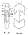
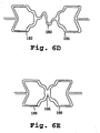
- Figs. 6D-6E illustrate two further embodiment of a connecting segment in accordance with the invention.
- the connecting segment 180 is an S-shaped member joining looped members 182, 184.
- the connecting segment 186 is a butt-weld joint between looped extremities 188, 190.
- connencting segments can be used in a single stent, to alter the rigidity and tractability of the stent.
- a more rigid connecting segment such as the weld joint of Fig. 6E can be used to join pluralities at the ends of the stent, for good tractability, and more flexible connecting segments can be used to join inner stent pluralities to maintain flexibility.
- the stent of the present invention is its capability to expand from a low-profile diameter to a diameter of substantial size while maintaining structural integrity, e.g ., radial strength. Also important is that the expansion ratio of the stent, that is, the ratio of the stent's expanded diameter to the stent's unexpanded diameter, is readily varied according to the number of unit cells in the plurality and the dimensions of the unit cell, as is evident from the discussion above. Typically, the number of unit cells in a plurality for use in forming a stent in accordance with the invention is between 3-500, more preferably between 3-150, and most preferably between 3-100. The expansion ratio of the stent can also be varied by changing the axial length of the unit cell.
- Axial length is taken as the longitudinal or axial distance between the axial extremities in a unit cell and is indicated in Fig. 5A as l c .
- Stents prepared in support of the present invention have typical expansion ratios of between 1-10. It will be appreciated based on the above description of the stent that for any selected application - from the smallest ducts in the body to the largest vessels -- the stent of the invention can be tailored through selection of the number and size of unit cells.
- an exemplary stent for use in a vessel of the coronary system where the vessel has a size of about 2-5 mm, is composed of a plurality of nine unit cells, where each unit cell has an axial length of 3.2 mm. This stent has an expansion ratio of about 5.
- cranial artery (1-3 mm), aorta (2-5 cm), splenic artery (3-6 mm), vena cava (3-5 mm), renal artery (3-5 mm), vessels of the carotid system, such as carotid artery (up to 1.5 cm), internal and external carotid (5 mm), subclavian artery, vertebral artery, brachial artery, iliac vein (1-2 mm), femoral vein or artery, popliteal artery or vein (3-5 mm).
- Stents made in support of the invention were mounted on a balloon of a balloon catheter and expanded by inflating the balloon to a pressure between 4-12 atm.
- the stents had an initial diameter of 1.35 mm and were expanded to between 3.3-3.86 mm, depending on the inflation pressure.
- the final expansion diameter of the stent was measured and compared to the expansion diameter measured when the balloon was inflated.
- Stent of the present invention had a recoil on the order of 1-1.5% (taken as the stent diameter with balloon inflated to the diameter after balloon deflation).
- the recoil of commercially available stents were determined by the same procedure, and found to have recoils on the order of 3-7%.
- the stent of the present invention also provides the advantageous feature of minimal axial shortening upon radial expansion.
- the length of the stent after expansion was measured and compared to the length of the stent prior to expansion.
- the length of the stents of the present invention decreased by less than 0.5 %, typically by about 0.2-0.5% after expansion. In comparison, commercially available stents decreased in length after radial expansion by 3-8 %.
- the stent described above is preferably constructed of a biocompatible material having good mechanical strength, such as those listed above. It will be appreciated that the radial strength of the stent - that is, its ability to prevent restenosis or to maintain vessel patency, and further to prevent vessel recoil and vessel spasms -- is in part a of function of the material from which it is formed and the design and configuration of the stent. Preferred materials for forming the stent include stainless steel, platinum and tantalum and alloys.
- the stent can be formed from a flat sheet or a tubular structure of material by chemically etching, laser cutting or by electronic discharge machining. A preferred method of making the stent of the invention is by laser cutting, and suitable methods and apparatus are known to those in the art.
- the stent, after laser cutting or machining can be electropolished, annealed and/or passivated as desired.
- the stent or a portion of the stent can also be plated or coated with an agent to provide lubricity and/or visibility.
- the stent can be coated in whole or in part with a radiopaque material or plated with platinum or gold to provide improved visibility during fluoroscopy.
- the stent described herein is used as a scaffold or structural member for carrying a polymer stent or sheath which preferably contains a therapeutic agent.
- the polymer stent is preferably carried on the outer surface of the structural stent for coexpansion with the structural stent in response to an applied force.
- An example of a co-expandable metal/polymer stent is described in U.S. Patent No. 5,674,242 .
- the stent of the present invention is particularly suited for use as a structural stent because of the uniform nature of the reticulated structure of the stent in its open, expanded condition.
- a polymer member carried about the outer periphery of the expanded structural stent is sufficiently supported to prevent the polymer from 'sagging' and potentially obstructing the lumen.
- the stent of the invention can be tailored for the embodiment, by forming notches or depressions in the structure where the coextensive polymer stent is in contact. In this way, the profile of the polymer/metal stent is not increased.
- Figs. 7A-7D illustrate introduction, expansion and deployment of the stent of the invention in a body lumen.
- the stent of the invention is suitable for use in a variety of applications, including, but not limited to, prevention of restenosis, reinforcement of reopened, previously obstructed bile ducts and support of narrowing lumens, such as the esophagus, intestine or urethra.
- a stent 180 is mounted on a balloon portion 182 of a catheter 184.
- the stent is secured on the catheter by simply compressing it in place for a snug fit over the balloon.
- Other means to secure the stent to the balloon include temporary adhesives or a withdrawable sleeve, or through ridges or collars on the balloon to restrain lateral movement of the stent.
- the catheter-stent assembly of Fig. 7A is then advanced through a body lumen of a patient to a treatment site, as shown in Fig. 7B .
- balloon 182 is positioned at the site it is to be implanted, typically across a lesion such as a plaque deposit 186 within a vessel 188
- the balloon portion of the catheter is inflated by known means, as depicted in Fig. 7C .
- the inflation of the balloon causes expansion of the stent from its small-diameter, unexpanded condition of Fig. 7A to its larger-diameter, expanded condition.
- the stent radially expands and presses against the lesion, contacting the vessel wall and exerting a radial pressure on the vessel wall.
- the balloon is then deflated and the catheter is removed from the vessel.
- the stent remains in its expanded form within the vessel, as shown in Fig. 7D , to prevent reclosure or obstruction of the vessel.
- the basic unit cell of the invention provides a structure which radially expands with minimal axial shortening.
- the expansion ratio of the unit cell is readily varied through selection of the dimensions of the unit cell components. Any number of unit cells can be joined radially and axially to form an expandable structure, such as a stent for insertion into a body lumen. It will of course be appreciated that the unit cell will have application in other types of medical device or in other fields which use a radially expandable member.
Abstract
Description
- The present invention relates generally to medical devices, and particularly to a unit cell for use in an expandable endoprosthesis device, more generally called a stent, and to a stent composed of such unit cells.
- Stents are generally cylindrically shaped devices which are radially expandable for implantation into a body lumen for holding open a segment of a blood vessel or other anatomical lumen. Stents have found a particular use in maintaining vessel patency following angioplasty, e.g. , in preventing restenosis of the vessel.
- Stents are typically inserted into the damaged vessel by mounting the stent on a balloon catheter and advancing the catheter to the desired location in the patient's body, inflating the balloon to expand the stent and then deflating the balloon and removing the catheter. The stent in its expanded condition in the vessel exerts a radial pressure on the vessel wall at the lesion site, to counter any tendency of the vessel to close.
- Although a variety of stents have been proposed, none to date has proven to be entirely satisfactory. For example, one problem with prior art stents has been contraction of the stent along its longitudinal length upon radial expansion of the stent. This can cause problems in correctly placing the stent within the vessel.
- Another problem with prior art stents has been the limited range of expandability. Some stents expand only to a limited degree, necessitating fabrication of stents in a range of diameters. increasing cost of manufacture and posing difficulty in selecting the proper stent size for the vessel to be treated.
- Another problem area has been a lack of control over the final, expanded diameter of the stent. The expansion of the stents is a function of the particular design or configuration and the spring constant and modulus of elasticity of the material used to manufacture the stent. Many stents because of their design and configuration exhibit recoil after expansion, making secure placement of the stent at the treatment site difficult. Poor contact between the stent and the vessel wall not only allows for some closure of the vessel, but can lead to more serious complications including migration of the stent away from the desired location. This problem is not readily solved by attempting to compensate for recoil by selecting an oversized stent, since improper selection may result in a stent which exerts to much force of the vessel, leading to an increase in the possibility of vessel injury, such as dissection or intimal hyperplasia.
- Another problem area has been in meeting the requirement that the stent be capable of maintaining the radial rigidity and strength needed to hold open a vessel while at the same time maintaining the longitudinal flexibility of the stent to facilitate its delivery. Placement of stents often involves advancing the stent-catheter assembly through tortuous vascular paths to the treatment site.
- It is also important that the stent have a low-profile for intra-luminal delivery and that it be suited for deployment by a delivery system that is reliable and easy to operate.
-
WO 97/32543 WO 97/32543 - It is one object of the present invention to provide a stent which substantially overcomes the limitations of the prior art.
- It is another object of the present invention to provide a stent having a selectively variable radial rigidity and longitudinal flexibility.
- It is another object of the present invention to provide a stent which does not exhibit significant recoil after implantation.
- It is a further object of the present invention to provide a stent having the above features and further capable of carrying a polymer member thereon.
- These and other objects are achieved with the stent as recited in the claims.
- Generally, the invention relates to a stent including unit cells adapted to be expanded to conform to the dimensions of a vessel. The unit cell may include:
- (i) an elongate connecting bar extending in a direction normal to the direction of stent expansion,
- (ii) associated with each end of said connecting bar, a first arm and a second arm, each arm being attached to the connecting bar associated end at an inner arm end for pivotal movement away from one another with stent expansion; the first and second arms having outer arm ends which are moved outwardly, with respect to the connecting bar, with such pivotal movement, and
- (iii) an expandable looped member connecting the outer arm ends in each pair of first and second arms; the looped member having an axial extremity which moves axially inwardly, with respect to the associated connecting bar end, with stent expansion.
- The arms and expandable looped members are constructed and dimensioned so that the radial outward distance traveled by the arms' outer ends in each pair of first and second arms is approximately equal to the axial inward distance traveled by the associated looped member extremity, as the stent is expanded.
- In one embodiment of the unit cell, the first and second arms in each pair are connected to the respective looped members through a shoulder member. The shoulder member can be a U-shaped, N-shaped or W-shaped shoulder member.
- In a preferred embodiment, the looped members of the unit cell have an undulating configuration.
- In another aspect, the invention includes a stent adapted to be expanded to conform to the dimensions of a vessel, comprising a plurality of unit cells as described above.
- In one embodiment, the stent is composed of a first plurality of unit cells connected to one or more axially adjacent plurality of unit cells by at least one connecting segment extending between two axially adjacent axial extremities. Each plurality of unit cells can include between about 3-500 unit cells.
- The stent has an expansion ratio, taken as the diameter of the stent after expansion to the diameter before expansion, of between about 1-10. In various embodiments, the expansion ratio is varied by varying the axial length, taken as the distance between axial extremities in a unit cell, of the unit cells in each plurality of unit cells, or by varying the number of unit cells in each plurality.
- In another embodiment of the invention, the stent further includes an outer stent surface on which a polymer stent is carried. The stent and polymer stent are designed for coexpansion in response to an applied force.
- These and other objects and features of the invention will be more fully appreciated when the following detailed description of the invention is read in conjunction with the accompanying drawings.
-
-
Figs. 1A-1B are perspective-elevational views of one embodiment of the stent of the present invention, where the stent is shown in its small-diameter, unexpanded condition (Fig. 1A ) (the backside of the stent is not shown for clarity) and in its large-diameter, expanded condition (Fig. 1B ); -
Figs. 2A-2B are plan views showing the structural detail of a unit cell according to different embodiments of the invention; -
Figs. 3A-3B are plan views showing the unit cell of the stent ofFig. 1 , where the unit cell is shown in its unexpanded condition (Fig. 3A ) and in its expanded condition (Fig. 3B ); -
Figs. 4A-4B are plan views of a unit cell according to other embodiments of the present invention, where the connecting bar is modified to provide increased flexibility; -
Figs. 5A-5B are plan views of a unit cell (Fig. 5A ) and a plurality of unit cells (Fig. 5B ) showing the dimensions of the unit cell and a plurality thereof; -
Figs. 6A-6C are plan views of the stent of the invention which illustrate various embodiments of a connecting segment for axially connecting a plurality of unit cells; -
Figs. 6D-6E shows other embodiments of the connecting segment for joining unit cells and pluralities of unit cells in a stent of the invention; and -
Figs. 7A-7D illustrate introduction, expansion and deployment of the stent of the invention in a vessel. - Referring to
Fig. 1A , an embodiment of the stent, or endovascular support device, of the present invention is shown.Stent 10 is shown in its unexpanded, small diameter condition for insertion in a vessel. The back side of the cylindrical stent is not shown for clarity purposes.Stent 10 is composed of aplurality 12 of unit cells, such asunit cell 14, which will be described hereinbelow.Unit cell 14 is joined in a radial direction, which is indicated in the figure byarrow 15, tounit cell 16, which is connected tounit cell 18, and so on to formplurality 12.Plurality 12 is connected in an axial direction, that is, in a direction normal to the radial direction of stent expansion, as indicated byarrow 19, to a second plurality ofunit cells 20.Stent 10 is illustrated with two plurality of unit cells, where each plurality includes nine unit cells, it will be appreciated that any number of pluralities containing any number of unit cells can be selected. as will be described below, depending on the desired stent expansion ratio and the size or length of the lesion to be treated. -
Stent 10 is adapted to be expanded to conform to the dimensions of a vessel. Typically, the stent is mounted on an expandable member of a delivery catheter, for example a balloon, and the catheter-stent assembly is introduced into a body lumen for deployment of the stent at the implantation site by inflation of the balloon and expansion of the stent. - The stent of
Fig. 1A in its expanded, larger-diameter form is shown inFig. 1B . The stent, and more particularly, the unit cells of the stent, are constructed and dimensioned, as will be described below, so that the stent radially expands with limited contraction in the axial direction, e.g., along the length of the stent which is indicated inFig. 1B byarrow 19. As can be seen inFig. 1B , the stent has an open reticulated structure allowing for blood perfusion over a substantial portion of the vessel wall against which the stent is biased, to facilitate healing and repair of the damaged vessel. - The features of the unit cell for use in the stent will be presented through illustration of various embodiments of the unit cell, as shown in
Figs. 2-4 . With initial reference toFig. 2A , aunit cell 24 in its unexpanded, small-diameter condition is shown. The unit cell includes anelongate bar 26, also referred to herein as a connecting bar or an elongate connecting bar, which extends in a direction normal to the direction of stent expansion. The direction of stent expansion is indicated in the figure byarrow 27. Associated with eachend bar end 28 and arm pair 34 onbar end 30. Arm pair 34 includes afirst arm 36 and asecond arm 38 attached to the associated bar end at inner arm ends 36a, 38a.Arms Fig. 3 . - With continuing reference to
Fig. 2A ,arms arm pair 32 at the opposite end of the connecting bar, are attached at an outer arm end, such as ends 36b. 38b, to an expandable looped member, such asmember 40. The arm pairs are attached to their respective looped members throughU-shpaed shoulder members member 40 includes anaxial extremity 46, taken as the tip or nose portion of loopedmember 40, e.g, that portion which is, with respect to the drawing, 'below' dashedline 48. - As noted above, the stent arm pairs are attached to each end of the connecting bar for pivotal movement away from the opposing arm in each pair, and away from the connecting bar, for stent expansion. The outer arm ends of each arm pair move in an outward direction, away from the connecting bar and travel along a path that has a radial and an axial component. The distance the outer arm ends travel in the axial outward direction, that is in the axial direction away from the connecting bar, is approximately equal to the axial inward distance traveled by the looped member extremity. This feature of the invention is illustrated more fully below with respect to
Figs. 3A-3B . - It will be appreciated that the U-shaped shoulder member of
Fig. 2A can have a variety of configurations, such as an N-shape or a W-shape as illustrated inFig. 2B . InFig. 2B ,stent 70 includes arm pairs 72, 74 connected to elongatebar 76. Thefirst arm 78 and thesecond arm 80 ofarm pair 72 are connected to an expandable loopedmember 82 at outer arm ends 78b, 80b, through W-shapedshoulder members - Turning now to
Figs. 3A-3B , a preferred embodiment of the unit cell of the invention is shown, the illustrated unit cell corresponding to the unit cell of the stent shown inFigs. 1A-1B .Unit cell 90 is shown inFig. 3A in its small-diameter, unexpanded condition and includes a connectingbar 92. Associated with eachend arms arms arm pair 98.Arms end 94 at inner arm ends 102a, 104a for pivotal movement away from one another with stent expansion. The first and second arms in each pair ofarms arms member 106, which include an axial extremity, such asextremity 108, taken as the nose portion 'above' (with respect to the drawing) dashedline 110. The first and second arms are joined to the looped member throughshoulder members 112. 114, which, in this embodiment, are U-shaped members. - In the embodiment shown in
Fig. 3A , the axial extremity in each of the expandable looped members has an undulating or wavy configuration. The undulating configuration provides several features that will be more fully described below, such as an increase in the expansion ratio of the unit cell and of a stent composed of such unit cells with minimal change in the length of the unit cell; a decrease in the occurrence of 'flaring', caused when the unit cell radially expands unevenly as when the looped member extremities do not radially expand as fully as the arm pairs of the unit cell; and a decrease in stress in the expandable looped by a more even distribution of force during placement and expansion. - The expansion of the unit cell and movement of its structural components will now be described with respect to
Fig. 3B. Fig. 3B shows the unit cell ofFig. 3A in its expanded, large-diameter condition and like structural elements are identified according to the notation set forth inFig. 3A . The unit cell is expanded in response to an applied external force, for example, where the unit cell is part of a stent, the stent is mounted on an expanding means, such as a balloon of a balloon catheter, and expanded by inflation of the balloon. In response to the applied force, expansion of the unit cell is achieved by pivotal movement of the arms attached to each end of the elongate bar. The arms pivot at the point of attachment of the inner arm ends to the connecting bar ends and move away from each other in an outward direction. "Outward" as used herein is with respect to the connecting bar, where an outward direction refers to movement away from the connecting bar. - As the arms move outward, the expandable looped member is caused to move inward, which as used herein refers to movement toward the connecting bar, and in this case toward the associated end of the connecting bar. The connecting bar stabilizes the unit cell and provides rigidity for strength. More importantly, the ends of the central bar act as pivot points, allowing for expansion of the unit cell, and at the same time the central bar prevents shortening of the unit cell during expansion.
- The unit cell for use in a stent must impart to the stent sufficient flexibility to enable tracking of the stent through often tortuous vascular paths for placement at the treatment site. At the same time, the stent must be strong enough radially to hold open a body lumen.
- The unit cell of the invention provides a stent having both longitudinal flexibility and radial strength. An important advantage provided by the unit cell of the invention is that the longitudinal flexibility is readily varied through simple modifications of the elements of the unit cell. For example, embodiments of the unit cell having greater flexibility than the embodiment of
Fig. 3 are shown inFigs. 4A-4B . In the embodiment ofFig. 4A ,unit cell 120 includes a connectingbar 122 with a pair ofarms bar 122 includes aU-shaped loop 134. The loop provides longitudinal flexibility to the unit cell, which lends flexibility to a stent which is formed of a plurality of such unit cells. Theunit cell 136 ofFig. 4B includes connectingbar 137 having an S-shapedmember 138 for added flexibility. - The flexibility of the unit cell can also be varied by changing the dimensions of the unit cell, e.g., the length and width of the unit cell, the length and width of the unit cell components as well as the relative dimensions. For example, and with reference to
Fig. 5A , the length of the unit cell, lc , is varied according to the length a of the connecting bar and the length b of the arms and looped members. Typically, the length of the unit cell lc is between 1-10 mm, more preferably between 2-8 mm and most preferably between 2-6 mm. Length b is determined primarily by the length of the expandable looped member, where the relative dimension of the axial nose length b1 to length b is variable to vary the flexibility of the unit cell. The flexibility of the unit cell is also varied according to length a of the connecting bar, where a shorter connecting bar results in a more flexible and tractable unit cell. Typical dimensions for a, the length of the connecting bar, are between about 1.5-2.5 mm. Length b is generally between 1.5-4 mm, with b1 between 0.50-1.25 mm. - With continuing reference to
Fig. 5A , the width wc of the unit cell is variable according to the material from which the unit cell is made and its dimensions. Typically, the unit cell is prepared from a suitable biocompatible materials such as stainless steel, tungsten, titanium, tantalum, gold, platinum and alloys and combinations of these materials, as well as shape-memory alloys and high strength thermoplastic polymers. The dimensions c and d inFig. 5A are readily varied according to material and material dimensions. Dimension e corresponds to the dimension of the arm pairs and is variable. Typical dimensions for the overall width of the unit cell, wc , are between 0.40-4.0 mm, with c generally between 0.025-0.13 mm and d between 0.03-0.10 mm and e between 0.04-0.1 mm. - It will be appreciated that dimensions c, d and e can be the same or different within a unit cell. In particular, dimension e is varied to alter the strength and rigidity of the unit cell, particularly when the unit cell is in its expanded condition. It will also be appreciated that the unit cell dimensions, particularly dimensions c and e can vary within a plurality of unit cells and between unit cell pluralities, as will be discussed below.
-
Fig. 5B shows six unit cells joined together to form a plurality, for use in forming a stent in accordance with the invention. The unit cells are joined along adjacent straight portions of looped member extremities, as can be seen in the figure at dimension f. It will be appreciated that f is variable according to the dimension of the looped member and the degree to which the adjacent cells are merged or overlapped. The diameter of the stent ds is determined by width of the unit cell and the number n of unit cells so joined. The stent length is determined by the length of the unit cell lc and the number m of pluralities joined in an axial direction. In this way the stent diameter and length is readily varied to treat vessels of any diameter and lesions of any length. -
Figs. 6A-6C are plan views of stents according to the invention composed of unit cells as described above. InFig. 6A ,stent 140 is composed of m pluralities of unit cells, where m in this embodiment is four, e.g.,pluralities - With continuing reference to
Fig. 6A ,pluralities segments Fig. 6E ) or a distinct segment (Figs. 6A-6D ). The connecting segment can be an integral part of the unit cells with which it is in contact, or it can be formed independently of the same or a different material and secured to the nose portion of the looped extremity of the unit cells. The number and position of the connecting segments joining pluralities can be varied to alter the flexibility of the stent, as can the structure of the connecting segment itself, as will be seen in the embodiments ofFigs. 6B-6E below.Figs. 6B-6E show alternative embodiments of the connecting segment. InFig. 6B ,stent 160 is formed of three pluralities of unit cells, 162, 164, 166. The pluralities are joined by connecting segments, such assegment 168, between axially adjacent unit cells. The connecting segments are a U-shaped loop, which provides increased tractability and flexibility to the stent, relative to the embodiment ofFig. 6A . -
Fig: 6C shows astent 170 where pluralities ofunit cells segment 178. It will be appreciated that in the embodiments ofFigs. 6B-6C the number and position of connecting segments between pluralities is variable. -
Figs. 6D-6E illustrate two further embodiment of a connecting segment in accordance with the invention. In these figures, the connecting segment joining the axial extremities of looped members in shown, rather than the entire stent. In the embodiment ofFig. 6D , the connectingsegment 180 is an S-shaped member joining loopedmembers Fig. 6E , the connectingsegment 186 is a butt-weld joint between loopedextremities - It will be appreciated that different connencting segments can be used in a single stent, to alter the rigidity and tractability of the stent. For example, a more rigid connecting segment such as the weld joint of
Fig. 6E can be used to join pluralities at the ends of the stent, for good tractability, and more flexible connecting segments can be used to join inner stent pluralities to maintain flexibility. - One important feature of the stent of the present invention is its capability to expand from a low-profile diameter to a diameter of substantial size while maintaining structural integrity, e.g., radial strength. Also important is that the expansion ratio of the stent, that is, the ratio of the stent's expanded diameter to the stent's unexpanded diameter, is readily varied according to the number of unit cells in the plurality and the dimensions of the unit cell, as is evident from the discussion above. Typically, the number of unit cells in a plurality for use in forming a stent in accordance with the invention is between 3-500, more preferably between 3-150, and most preferably between 3-100. The expansion ratio of the stent can also be varied by changing the axial length of the unit cell. Axial length is taken as the longitudinal or axial distance between the axial extremities in a unit cell and is indicated in
Fig. 5A as lc . The longer the axial length, the larger the expansion ratio of the stent, and the more unit cells in each plurality, the larger the expansion ratio. - Stents prepared in support of the present invention have typical expansion ratios of between 1-10. It will be appreciated based on the above description of the stent that for any selected application - from the smallest ducts in the body to the largest vessels -- the stent of the invention can be tailored through selection of the number and size of unit cells. By way of example, an exemplary stent for use in a vessel of the coronary system, where the vessel has a size of about 2-5 mm, is composed of a plurality of nine unit cells, where each unit cell has an axial length of 3.2 mm. This stent has an expansion ratio of about 5. In addition to vessels in the coronary system, the following vessels are contemplated for use with the stent of the invention: cranial artery (1-3 mm), aorta (2-5 cm), splenic artery (3-6 mm), vena cava (3-5 mm), renal artery (3-5 mm), vessels of the carotid system, such as carotid artery (up to 1.5 cm), internal and external carotid (5 mm), subclavian artery, vertebral artery, brachial artery, iliac vein (1-2 mm), femoral vein or artery, popliteal artery or vein (3-5 mm).
- Another important feature of the stent of the present invention is a minimal elastic recoil after expansion to its large-diameter condition. Stents made in support of the invention were mounted on a balloon of a balloon catheter and expanded by inflating the balloon to a pressure between 4-12 atm. The stents had an initial diameter of 1.35 mm and were expanded to between 3.3-3.86 mm, depending on the inflation pressure. After deflation of the balloon, the final expansion diameter of the stent was measured and compared to the expansion diameter measured when the balloon was inflated. Stent of the present invention had a recoil on the order of 1-1.5% (taken as the stent diameter with balloon inflated to the diameter after balloon deflation). The recoil of commercially available stents were determined by the same procedure, and found to have recoils on the order of 3-7%.
- The stent of the present invention also provides the advantageous feature of minimal axial shortening upon radial expansion. During the testing procedure described above for recoil, the length of the stent after expansion was measured and compared to the length of the stent prior to expansion. The length of the stents of the present invention decreased by less than 0.5 %, typically by about 0.2-0.5% after expansion. In comparison, commercially available stents decreased in length after radial expansion by 3-8 %.
- The stent described above is preferably constructed of a biocompatible material having good mechanical strength, such as those listed above. It will be appreciated that the radial strength of the stent - that is, its ability to prevent restenosis or to maintain vessel patency, and further to prevent vessel recoil and vessel spasms -- is in part a of function of the material from which it is formed and the design and configuration of the stent. Preferred materials for forming the stent include stainless steel, platinum and tantalum and alloys. The stent can be formed from a flat sheet or a tubular structure of material by chemically etching, laser cutting or by electronic discharge machining. A preferred method of making the stent of the invention is by laser cutting, and suitable methods and apparatus are known to those in the art. The stent, after laser cutting or machining can be electropolished, annealed and/or passivated as desired. The stent or a portion of the stent can also be plated or coated with an agent to provide lubricity and/or visibility. For example, the stent can be coated in whole or in part with a radiopaque material or plated with platinum or gold to provide improved visibility during fluoroscopy.
- In another embodiment of the invention, the stent described herein is used as a scaffold or structural member for carrying a polymer stent or sheath which preferably contains a therapeutic agent. The polymer stent is preferably carried on the outer surface of the structural stent for coexpansion with the structural stent in response to an applied force. An example of a co-expandable metal/polymer stent is described in
U.S. Patent No. 5,674,242 . - The stent of the present invention is particularly suited for use as a structural stent because of the uniform nature of the reticulated structure of the stent in its open, expanded condition. A polymer member carried about the outer periphery of the expanded structural stent is sufficiently supported to prevent the polymer from 'sagging' and potentially obstructing the lumen. The stent of the invention can be tailored for the embodiment, by forming notches or depressions in the structure where the coextensive polymer stent is in contact. In this way, the profile of the polymer/metal stent is not increased.
-
Figs. 7A-7D illustrate introduction, expansion and deployment of the stent of the invention in a body lumen. It will be appreciated that the stent of the invention is suitable for use in a variety of applications, including, but not limited to, prevention of restenosis, reinforcement of reopened, previously obstructed bile ducts and support of narrowing lumens, such as the esophagus, intestine or urethra. - With continuing reference to
Figs. 7A-7D , and initially with particular reference toFig. 7A , astent 180 is mounted on aballoon portion 182 of acatheter 184. The stent is secured on the catheter by simply compressing it in place for a snug fit over the balloon. Other means to secure the stent to the balloon include temporary adhesives or a withdrawable sleeve, or through ridges or collars on the balloon to restrain lateral movement of the stent. - The catheter-stent assembly of
Fig. 7A is then advanced through a body lumen of a patient to a treatment site, as shown inFig. 7B . Onceballoon 182 is positioned at the site it is to be implanted, typically across a lesion such as aplaque deposit 186 within avessel 188, the balloon portion of the catheter is inflated by known means, as depicted inFig. 7C . The inflation of the balloon causes expansion of the stent from its small-diameter, unexpanded condition ofFig. 7A to its larger-diameter, expanded condition. The stent radially expands and presses against the lesion, contacting the vessel wall and exerting a radial pressure on the vessel wall. - The balloon is then deflated and the catheter is removed from the vessel. The stent remains in its expanded form within the vessel, as shown in
Fig. 7D , to prevent reclosure or obstruction of the vessel. - From the foregoing, it can be appreciated how various features and objects of the invention are met. The basic unit cell of the invention provides a structure which radially expands with minimal axial shortening. The expansion ratio of the unit cell is readily varied through selection of the dimensions of the unit cell components. Any number of unit cells can be joined radially and axially to form an expandable structure, such as a stent for insertion into a body lumen. It will of course be appreciated that the unit cell will have application in other types of medical device or in other fields which use a radially expandable member.
- Although the invention has been described with respect to particular embodiments, it will be apparent to those skilled in the art that various changes and modifications can be made without departing from the invention.
Claims (9)
- A stent (10; 70) in an unexpanded condition, comprising:a plurality of interconnected unit cells including a first plurality of unit cells (12) and a second plurality of unit cells (20), each unit cell comprising:wherein the first and second ends (28, 30) of the connecting bar (26; 76) act as pivot points for the first and second pairs of pivot arms (32, 34; 72, 74), allowing for expansion of the unit cell, and at the same time the connecting bar (26; 76) prevents shortening of the unit cell during expansion;an elongate connecting bar (26; 76) extending in an axial direction and having a first end (28) and a second end (30);associated with the first end (28) of the connecting bar (26; 76) are a first pair of pivot arms (32; 72), a first pair of shoulder members (84, 86) and a first expandable looped member (82), wherein each arm (78, 80) of the first pair of pivot arms (32;72) is connected to the first end (28) of the connecting bar (26; 76) at an inner arm end and connected to one shoulder member of the first pair of shoulder members (84, 86) at an outer arm end (78b, 80b), wherein the first expandable looped member (82) spans between the first pair of shoulder members (84, 86);associated with the second end (30) of the connecting bar (26; 76) are a second pair of pivot arms (34; 74), a second pair of shoulder members (42, 44) and a second expandable looped member (40), wherein each arm (36, 38) of the second pair of pivot arms (34; 74) is connected to the second end (30) of the connecting bar (26; 76) at an inner arm end (36a, 38a) and connected to one shoulder member of the second pair of shoulder members (42, 44) at an outer arm end (36b, 38b), wherein the second expandable looped member (40) spans between the second pair of shoulder members (42, 44);
wherein a first expandable looped member (82)of the first plurality of unit cells (12) is connected to a second expandable looped member (40) of the second plurality of unit cells (20) by a connecting segment,
wherein the expandable looped members of two adjacent unit cells within the first plurality of unit cells (12) are joined along adjacent straight portions thereof, and
wherein, upon expansion, the outer arm ends of each arm pair are adapted to move in an outward direction, away from the connecting bar and travel along a path that has a radial and an axial component. - The stent of claim 1, wherein a shoulder member (84, 86) comprises a W-shape or an N-shape.
- The stent of claim 1, wherein the first plurality of unit cells (12) is axially adjacent to the second plurality of unit cells (20).
- The stent of claim 1, wherein the first expandable looped member of a unit cell in the first plurality of unit cells (12) is connected to the first expandable looped member of an adjacent unit cell also in the first plurality of unit cells (12).
- The stent of claim 1, wherein adjacent unit cells of the first plurality of unit cells (12) are connected in a circumferential direction.
- The stent of claim 1, wherein the connecting bar (26; 76) of a unit cell further comprises an S-shape.
- The stent of claim 1, wherein the connecting bar (26; 76) of a unit cell further comprises a U-shaped loop.
- The stent of claim 1, wherein said connecting segment comprises an S-shape.
- The stent of claim 1, wherein said connecting segment comprises a U-shaped loop.
Applications Claiming Priority (2)
| Application Number | Priority Date | Filing Date | Title |
|---|---|---|---|
| US09/053,887 US6019789A (en) | 1998-04-01 | 1998-04-01 | Expandable unit cell and intraluminal stent |
| EP99912902A EP1067881B1 (en) | 1998-04-01 | 1999-03-25 | Expandable unit cell and intraluminal stent |
Related Parent Applications (1)
| Application Number | Title | Priority Date | Filing Date |
|---|---|---|---|
| EP99912902A Division EP1067881B1 (en) | 1998-04-01 | 1999-03-25 | Expandable unit cell and intraluminal stent |
Publications (3)
| Publication Number | Publication Date |
|---|---|
| EP1616534A2 EP1616534A2 (en) | 2006-01-18 |
| EP1616534A3 EP1616534A3 (en) | 2006-01-25 |
| EP1616534B1 true EP1616534B1 (en) | 2009-03-04 |
Family
ID=21987226
Family Applications (2)
| Application Number | Title | Priority Date | Filing Date |
|---|---|---|---|
| EP05019233A Expired - Lifetime EP1616534B1 (en) | 1998-04-01 | 1999-03-25 | Intraluminal stent with expandable unit cell |
| EP99912902A Expired - Lifetime EP1067881B1 (en) | 1998-04-01 | 1999-03-25 | Expandable unit cell and intraluminal stent |
Family Applications After (1)
| Application Number | Title | Priority Date | Filing Date |
|---|---|---|---|
| EP99912902A Expired - Lifetime EP1067881B1 (en) | 1998-04-01 | 1999-03-25 | Expandable unit cell and intraluminal stent |
Country Status (10)
| Country | Link |
|---|---|
| US (2) | US6019789A (en) |
| EP (2) | EP1616534B1 (en) |
| JP (1) | JP4097402B2 (en) |
| CN (1) | CN1296398A (en) |
| AT (2) | ATE424165T1 (en) |
| AU (1) | AU760786B2 (en) |
| CA (1) | CA2326317C (en) |
| DE (2) | DE69928915T2 (en) |
| TW (1) | TW453190U (en) |
| WO (1) | WO1999049811A1 (en) |
Families Citing this family (186)
| Publication number | Priority date | Publication date | Assignee | Title |
|---|---|---|---|---|
| US7204848B1 (en) | 1995-03-01 | 2007-04-17 | Boston Scientific Scimed, Inc. | Longitudinally flexible expandable stent |
| US8663311B2 (en) | 1997-01-24 | 2014-03-04 | Celonova Stent, Inc. | Device comprising biodegradable bistable or multistable cells and methods of use |
| US8353948B2 (en) * | 1997-01-24 | 2013-01-15 | Celonova Stent, Inc. | Fracture-resistant helical stent incorporating bistable cells and methods of use |
| CN1626048B (en) * | 1997-01-24 | 2012-09-12 | 帕拉贡知识产权有限责任公司 | Expandable device having bistable spring construction |
| US20020133222A1 (en) * | 1997-03-05 | 2002-09-19 | Das Gladwin S. | Expandable stent having a plurality of interconnected expansion modules |
| IL128261A0 (en) | 1999-01-27 | 1999-11-30 | Disc O Tech Medical Tech Ltd | Expandable element |
| US20060271061A1 (en) * | 2001-07-25 | 2006-11-30 | Disc-O-Tech, Ltd. | Deformable tools and implants |
| DE19722384A1 (en) * | 1997-05-28 | 1998-12-03 | Gfe Ges Fuer Forschung Und Ent | Flexible expandable stent |
| EP0884029B1 (en) * | 1997-06-13 | 2004-12-22 | Gary J. Becker | Expandable intraluminal endoprosthesis |
| US5938697A (en) | 1998-03-04 | 1999-08-17 | Scimed Life Systems, Inc. | Stent having variable properties |
| US7208010B2 (en) * | 2000-10-16 | 2007-04-24 | Conor Medsystems, Inc. | Expandable medical device for delivery of beneficial agent |
| US20040254635A1 (en) * | 1998-03-30 | 2004-12-16 | Shanley John F. | Expandable medical device for delivery of beneficial agent |
| US7208011B2 (en) * | 2001-08-20 | 2007-04-24 | Conor Medsystems, Inc. | Implantable medical device with drug filled holes |
| US7500988B1 (en) * | 2000-11-16 | 2009-03-10 | Cordis Corporation | Stent for use in a stent graft |
| US6241762B1 (en) * | 1998-03-30 | 2001-06-05 | Conor Medsystems, Inc. | Expandable medical device with ductile hinges |
| DE19829702C1 (en) * | 1998-07-03 | 2000-03-16 | Heraeus Gmbh W C | Radially expandable support device V |
| US6461380B1 (en) | 1998-07-28 | 2002-10-08 | Advanced Cardiovascular Systems, Inc. | Stent configuration |
| US6755856B2 (en) * | 1998-09-05 | 2004-06-29 | Abbott Laboratories Vascular Enterprises Limited | Methods and apparatus for stenting comprising enhanced embolic protection, coupled with improved protection against restenosis and thrombus formation |
| US7887578B2 (en) | 1998-09-05 | 2011-02-15 | Abbott Laboratories Vascular Enterprises Limited | Stent having an expandable web structure |
| US6682554B2 (en) * | 1998-09-05 | 2004-01-27 | Jomed Gmbh | Methods and apparatus for a stent having an expandable web structure |
| US7815763B2 (en) * | 2001-09-28 | 2010-10-19 | Abbott Laboratories Vascular Enterprises Limited | Porous membranes for medical implants and methods of manufacture |
| US20020019660A1 (en) * | 1998-09-05 | 2002-02-14 | Marc Gianotti | Methods and apparatus for a curved stent |
| US6193744B1 (en) * | 1998-09-10 | 2001-02-27 | Scimed Life Systems, Inc. | Stent configurations |
| US6293967B1 (en) | 1998-10-29 | 2001-09-25 | Conor Medsystems, Inc. | Expandable medical device with ductile hinges |
| US6190403B1 (en) | 1998-11-13 | 2001-02-20 | Cordis Corporation | Low profile radiopaque stent with increased longitudinal flexibility and radial rigidity |
| US8092514B1 (en) * | 1998-11-16 | 2012-01-10 | Boston Scientific Scimed, Inc. | Stretchable anti-buckling coiled-sheet stent |
| US6530950B1 (en) * | 1999-01-12 | 2003-03-11 | Quanam Medical Corporation | Intraluminal stent having coaxial polymer member |
| US7621950B1 (en) | 1999-01-27 | 2009-11-24 | Kyphon Sarl | Expandable intervertebral spacer |
| US7018401B1 (en) | 1999-02-01 | 2006-03-28 | Board Of Regents, The University Of Texas System | Woven intravascular devices and methods for making the same and apparatus for delivery of the same |
| US6245101B1 (en) * | 1999-05-03 | 2001-06-12 | William J. Drasler | Intravascular hinge stent |
| US6290673B1 (en) | 1999-05-20 | 2001-09-18 | Conor Medsystems, Inc. | Expandable medical device delivery system and method |
| US20050060044A1 (en) * | 1999-08-05 | 2005-03-17 | Ed Roschak | Methods and devices for maintaining patency of surgically created channels in a body organ |
| US20030130657A1 (en) * | 1999-08-05 | 2003-07-10 | Tom Curtis P. | Devices for applying energy to tissue |
| US20050137715A1 (en) * | 1999-08-05 | 2005-06-23 | Broncus Technologies, Inc. | Methods and devices for maintaining patency of surgically created channels in a body organ |
| US7815590B2 (en) * | 1999-08-05 | 2010-10-19 | Broncus Technologies, Inc. | Devices for maintaining patency of surgically created channels in tissue |
| US20040073155A1 (en) * | 2000-01-14 | 2004-04-15 | Broncus Technologies, Inc. | Methods and devices for maintaining patency of surgically created channels in tissue |
| WO2001010314A2 (en) * | 1999-08-05 | 2001-02-15 | Broncus Technologies, Inc. | Methods and devices for creating collateral channels in the lungs |
| US6371980B1 (en) * | 1999-08-30 | 2002-04-16 | Cardiovasc, Inc. | Composite expandable device with impervious polymeric covering and bioactive coating thereon, delivery apparatus and method |
| US6679910B1 (en) * | 1999-11-12 | 2004-01-20 | Latin American Devices Llc | Intraluminal stent |
| US6280466B1 (en) * | 1999-12-03 | 2001-08-28 | Teramed Inc. | Endovascular graft system |
| AU2428201A (en) * | 1999-12-07 | 2001-06-18 | Edwards Lifesciences Corporation | Novel enhanced flexible expandable stents |
| US6355058B1 (en) * | 1999-12-30 | 2002-03-12 | Advanced Cardiovascular Systems, Inc. | Stent with radiopaque coating consisting of particles in a binder |
| US6451050B1 (en) | 2000-04-28 | 2002-09-17 | Cardiovasc, Inc. | Stent graft and method |
| US6520984B1 (en) | 2000-04-28 | 2003-02-18 | Cardiovasc, Inc. | Stent graft assembly and method |
| US20030114918A1 (en) | 2000-04-28 | 2003-06-19 | Garrison Michi E. | Stent graft assembly and method |
| US6616689B1 (en) * | 2000-05-03 | 2003-09-09 | Advanced Cardiovascular Systems, Inc. | Intravascular stent |
| US6799637B2 (en) | 2000-10-20 | 2004-10-05 | Schlumberger Technology Corporation | Expandable tubing and method |
| PT1328213E (en) | 2000-10-16 | 2005-10-31 | Conor Medsystems Inc | EXPANSIVE MEDICAL DEVICE FOR THE ADMINISTRATION OF A BENEFICIAL AGENT |
| US6764507B2 (en) | 2000-10-16 | 2004-07-20 | Conor Medsystems, Inc. | Expandable medical device with improved spatial distribution |
| US6783793B1 (en) * | 2000-10-26 | 2004-08-31 | Advanced Cardiovascular Systems, Inc. | Selective coating of medical devices |
| US7229472B2 (en) * | 2000-11-16 | 2007-06-12 | Cordis Corporation | Thoracic aneurysm repair prosthesis and system |
| US6942692B2 (en) * | 2000-11-16 | 2005-09-13 | Cordis Corporation | Supra-renal prosthesis and renal artery bypass |
| US20070031607A1 (en) * | 2000-12-19 | 2007-02-08 | Alexander Dubson | Method and apparatus for coating medical implants |
| US20020084178A1 (en) * | 2000-12-19 | 2002-07-04 | Nicast Corporation Ltd. | Method and apparatus for manufacturing polymer fiber shells via electrospinning |
| US20040030377A1 (en) * | 2001-10-19 | 2004-02-12 | Alexander Dubson | Medicated polymer-coated stent assembly |
| US7244272B2 (en) | 2000-12-19 | 2007-07-17 | Nicast Ltd. | Vascular prosthesis and method for production thereof |
| US6626935B1 (en) | 2000-12-21 | 2003-09-30 | Advanced Cardiovascular Systems, Inc. | Intravascular stent |
| US6929660B1 (en) | 2000-12-22 | 2005-08-16 | Advanced Cardiovascular Systems, Inc. | Intravascular stent |
| NO335594B1 (en) * | 2001-01-16 | 2015-01-12 | Halliburton Energy Serv Inc | Expandable devices and methods thereof |
| US20040102834A1 (en) * | 2001-02-01 | 2004-05-27 | Ryoji Nakano | Stent |
| US6964680B2 (en) * | 2001-02-05 | 2005-11-15 | Conor Medsystems, Inc. | Expandable medical device with tapered hinge |
| US20040073294A1 (en) | 2002-09-20 | 2004-04-15 | Conor Medsystems, Inc. | Method and apparatus for loading a beneficial agent into an expandable medical device |
| US6679911B2 (en) | 2001-03-01 | 2004-01-20 | Cordis Corporation | Flexible stent |
| US6790227B2 (en) * | 2001-03-01 | 2004-09-14 | Cordis Corporation | Flexible stent |
| US6740114B2 (en) * | 2001-03-01 | 2004-05-25 | Cordis Corporation | Flexible stent |
| AU784552B2 (en) * | 2001-03-02 | 2006-05-04 | Cardinal Health 529, Llc | Flexible stent |
| US7794219B2 (en) * | 2001-03-20 | 2010-09-14 | Nicast Ltd. | Portable electrospinning device |
| US6719804B2 (en) | 2001-04-02 | 2004-04-13 | Scimed Life Systems, Inc. | Medical stent and related methods |
| US6764505B1 (en) | 2001-04-12 | 2004-07-20 | Advanced Cardiovascular Systems, Inc. | Variable surface area stent |
| JP2005506112A (en) * | 2001-04-26 | 2005-03-03 | バスキュラー イノベイション,インコーポレイティド | Intraluminal device and method of making the same |
| US7087088B2 (en) * | 2001-05-24 | 2006-08-08 | Torax Medical, Inc. | Methods and apparatus for regulating the flow of matter through body tubing |
| US7862495B2 (en) * | 2001-05-31 | 2011-01-04 | Advanced Cardiovascular Systems, Inc. | Radiation or drug delivery source with activity gradient to minimize edge effects |
| US6939373B2 (en) * | 2003-08-20 | 2005-09-06 | Advanced Cardiovascular Systems, Inc. | Intravascular stent |
| US6629994B2 (en) | 2001-06-11 | 2003-10-07 | Advanced Cardiovascular Systems, Inc. | Intravascular stent |
| US7201940B1 (en) * | 2001-06-12 | 2007-04-10 | Advanced Cardiovascular Systems, Inc. | Method and apparatus for thermal spray processing of medical devices |
| US6635083B1 (en) | 2001-06-25 | 2003-10-21 | Advanced Cardiovascular Systems, Inc. | Stent with non-linear links and method of use |
| US6749629B1 (en) | 2001-06-27 | 2004-06-15 | Advanced Cardiovascular Systems, Inc. | Stent pattern with figure-eights |
| US7520892B1 (en) * | 2001-06-28 | 2009-04-21 | Advanced Cardiovascular Systems, Inc. | Low profile stent with flexible link |
| US6605110B2 (en) | 2001-06-29 | 2003-08-12 | Advanced Cardiovascular Systems, Inc. | Stent with enhanced bendability and flexibility |
| US6607554B2 (en) | 2001-06-29 | 2003-08-19 | Advanced Cardiovascular Systems, Inc. | Universal stent link design |
| US6656216B1 (en) * | 2001-06-29 | 2003-12-02 | Advanced Cardiovascular Systems, Inc. | Composite stent with regioselective material |
| US7842083B2 (en) * | 2001-08-20 | 2010-11-30 | Innovational Holdings, Llc. | Expandable medical device with improved spatial distribution |
| US7056338B2 (en) * | 2003-03-28 | 2006-06-06 | Conor Medsystems, Inc. | Therapeutic agent delivery device with controlled therapeutic agent release rates |
| US20050060042A1 (en) * | 2001-09-04 | 2005-03-17 | Broncus Technologies, Inc. | Methods and devices for maintaining surgically created channels in a body organ |
| US7708712B2 (en) | 2001-09-04 | 2010-05-04 | Broncus Technologies, Inc. | Methods and devices for maintaining patency of surgically created channels in a body organ |
| US20050137611A1 (en) * | 2001-09-04 | 2005-06-23 | Broncus Technologies, Inc. | Methods and devices for maintaining surgically created channels in a body organ |
| IES20010828A2 (en) * | 2001-09-12 | 2003-03-19 | Medtronic Inc | Medical device for intraluminal endovascular stenting |
| EP1516600B1 (en) * | 2001-09-18 | 2007-03-14 | Abbott Laboratories Vascular Enterprises Limited | Stent |
| US6620202B2 (en) | 2001-10-16 | 2003-09-16 | Scimed Life Systems, Inc. | Medical stent with variable coil and related methods |
| US20030077310A1 (en) * | 2001-10-22 | 2003-04-24 | Chandrashekhar Pathak | Stent coatings containing HMG-CoA reductase inhibitors |
| WO2003053284A1 (en) * | 2001-12-20 | 2003-07-03 | White Geoffrey H | An intraluminal stent and graft |
| US7473273B2 (en) * | 2002-01-22 | 2009-01-06 | Medtronic Vascular, Inc. | Stent assembly with therapeutic agent exterior banding |
| US7354450B2 (en) * | 2002-01-30 | 2008-04-08 | Boston Scientific Scimed, Inc. | Stent with wishbone connectors and serpentine bands |
| US20110306997A9 (en) * | 2002-02-21 | 2011-12-15 | Roschak Edmund J | Devices for creating passages and sensing for blood vessels |
| US7083822B2 (en) | 2002-04-26 | 2006-08-01 | Medtronic Vascular, Inc. | Overlapping coated stents |
| US7695427B2 (en) | 2002-04-26 | 2010-04-13 | Torax Medical, Inc. | Methods and apparatus for treating body tissue sphincters and the like |
| US20050197715A1 (en) * | 2002-04-26 | 2005-09-08 | Torax Medical, Inc. | Methods and apparatus for implanting devices into non-sterile body lumens or organs |
| US6656220B1 (en) | 2002-06-17 | 2003-12-02 | Advanced Cardiovascular Systems, Inc. | Intravascular stent |
| US6878162B2 (en) | 2002-08-30 | 2005-04-12 | Edwards Lifesciences Ag | Helical stent having improved flexibility and expandability |
| US9561123B2 (en) | 2002-08-30 | 2017-02-07 | C.R. Bard, Inc. | Highly flexible stent and method of manufacture |
| US20040127976A1 (en) * | 2002-09-20 | 2004-07-01 | Conor Medsystems, Inc. | Method and apparatus for loading a beneficial agent into an expandable medical device |
| CA2499594A1 (en) * | 2002-09-20 | 2004-04-01 | Conor Medsystems, Inc. | Expandable medical device with openings for delivery of multiple beneficial agents |
| US6786922B2 (en) * | 2002-10-08 | 2004-09-07 | Cook Incorporated | Stent with ring architecture and axially displaced connector segments |
| US7169178B1 (en) * | 2002-11-12 | 2007-01-30 | Advanced Cardiovascular Systems, Inc. | Stent with drug coating |
| US20040181186A1 (en) * | 2003-03-13 | 2004-09-16 | Scimed Life Systems, Inc. | Medical device |
| WO2004080357A1 (en) | 2003-03-14 | 2004-09-23 | Ferreyro Irigoyen Roque Humber | Hydraulic device for the injection of bone cement in percutaneous vertebroplasty |
| EP2289571B1 (en) * | 2003-03-28 | 2016-08-03 | Innovational Holdings, LLC | Implantable medical device with beneficial agent concentration gradient |
| US8066713B2 (en) | 2003-03-31 | 2011-11-29 | Depuy Spine, Inc. | Remotely-activated vertebroplasty injection device |
| US7169179B2 (en) * | 2003-06-05 | 2007-01-30 | Conor Medsystems, Inc. | Drug delivery device and method for bi-directional drug delivery |
| US20070032567A1 (en) * | 2003-06-17 | 2007-02-08 | Disc-O-Tech Medical | Bone Cement And Methods Of Use Thereof |
| US8415407B2 (en) | 2004-03-21 | 2013-04-09 | Depuy Spine, Inc. | Methods, materials, and apparatus for treating bone and other tissue |
| US8002740B2 (en) * | 2003-07-18 | 2011-08-23 | Broncus Technologies, Inc. | Devices for maintaining patency of surgically created channels in tissue |
| US8308682B2 (en) | 2003-07-18 | 2012-11-13 | Broncus Medical Inc. | Devices for maintaining patency of surgically created channels in tissue |
| US7785653B2 (en) * | 2003-09-22 | 2010-08-31 | Innovational Holdings Llc | Method and apparatus for loading a beneficial agent into an expandable medical device |
| US8579908B2 (en) | 2003-09-26 | 2013-11-12 | DePuy Synthes Products, LLC. | Device for delivering viscous material |
| US7198675B2 (en) | 2003-09-30 | 2007-04-03 | Advanced Cardiovascular Systems | Stent mandrel fixture and method for selectively coating surfaces of a stent |
| WO2005065578A2 (en) * | 2004-01-06 | 2005-07-21 | Nicast Ltd. | Vascular prosthesis with anastomotic member |
| US20050154447A1 (en) * | 2004-01-09 | 2005-07-14 | Medtronic Vascular, Inc. | Ostium stent system |
| US8858616B2 (en) * | 2004-03-16 | 2014-10-14 | Admedes Schuessler Gmbh | Stent having a bridge structure |
| CA2591543A1 (en) * | 2004-07-19 | 2006-02-09 | Broncus Technologies, Inc. | Methods and devices for maintaining patency of surgically created channels in a body organ |
| US8409167B2 (en) | 2004-07-19 | 2013-04-02 | Broncus Medical Inc | Devices for delivering substances through an extra-anatomic opening created in an airway |
| US7744641B2 (en) * | 2004-07-21 | 2010-06-29 | Boston Scientific Scimed, Inc. | Expandable framework with overlapping connectors |
| CA2575699C (en) | 2004-07-30 | 2014-07-08 | Disc-O-Tech Medical Technologies Ltd. | Methods, materials and apparatus for treating bone and other tissue |
| US20060064155A1 (en) * | 2004-09-01 | 2006-03-23 | Pst, Llc | Stent and method for manufacturing the stent |
| US7780721B2 (en) * | 2004-09-01 | 2010-08-24 | C. R. Bard, Inc. | Stent and method for manufacturing the stent |
| US7317331B2 (en) * | 2004-11-08 | 2008-01-08 | Tabula, Inc. | Reconfigurable IC that has sections running at different reconfiguration rates |
| US9586030B2 (en) * | 2004-12-23 | 2017-03-07 | Boston Scientific Scimed, Inc. | Fugitive plasticizer balloon surface treatment for enhanced stent securement |
| CN101573086A (en) * | 2005-02-17 | 2009-11-04 | 尼卡斯特有限公司 | Inflatable medical device |
| WO2006130873A2 (en) * | 2005-06-01 | 2006-12-07 | Broncus Technologies, Inc. | Methods and devices for maintaining surgically created channels in a body organ |
| US9381024B2 (en) * | 2005-07-31 | 2016-07-05 | DePuy Synthes Products, Inc. | Marked tools |
| US9918767B2 (en) | 2005-08-01 | 2018-03-20 | DePuy Synthes Products, Inc. | Temperature control system |
| US8360629B2 (en) | 2005-11-22 | 2013-01-29 | Depuy Spine, Inc. | Mixing apparatus having central and planetary mixing elements |
| US7867547B2 (en) | 2005-12-19 | 2011-01-11 | Advanced Cardiovascular Systems, Inc. | Selectively coating luminal surfaces of stents |
| US20070191926A1 (en) * | 2006-02-14 | 2007-08-16 | Advanced Cardiovascular Systems, Inc. | Stent pattern for high stent retention |
| EP3127508A1 (en) | 2006-02-14 | 2017-02-08 | Angiomed GmbH & Co. Medizintechnik KG | Highly flexible stent |
| US8066760B2 (en) * | 2006-04-18 | 2011-11-29 | Medtronic Vascular, Inc. | Stent with movable crown |
| US8003156B2 (en) | 2006-05-04 | 2011-08-23 | Advanced Cardiovascular Systems, Inc. | Rotatable support elements for stents |
| US20070283969A1 (en) * | 2006-06-12 | 2007-12-13 | Medtronic Vascular, Inc. | Method of Diagnosing and Treating Erectile Dysfunction |
| US8603530B2 (en) | 2006-06-14 | 2013-12-10 | Abbott Cardiovascular Systems Inc. | Nanoshell therapy |
| US8048448B2 (en) | 2006-06-15 | 2011-11-01 | Abbott Cardiovascular Systems Inc. | Nanoshells for drug delivery |
| US8017237B2 (en) | 2006-06-23 | 2011-09-13 | Abbott Cardiovascular Systems, Inc. | Nanoshells on polymers |
| DE602007014061D1 (en) * | 2006-08-22 | 2011-06-01 | Abbott Cardiovascular Systems | INTRAVASCULAR STENT |
| US8211163B2 (en) * | 2006-09-13 | 2012-07-03 | Boston Scientific Scimed, Inc. | Hybrid symmetrical stent designs |
| WO2008032322A2 (en) | 2006-09-14 | 2008-03-20 | Depuy Spine, Inc. | Bone cement and methods of use thereof |
| US8778009B2 (en) * | 2006-10-06 | 2014-07-15 | Abbott Cardiovascular Systems Inc. | Intravascular stent |
| CA2747850C (en) | 2006-10-19 | 2013-05-14 | Depuy Spine, Inc. | Fluid delivery system |
| CA2667318C (en) | 2006-10-22 | 2016-09-13 | Idev Technologies, Inc. | Methods for securing strand ends and the resulting devices |
| EP2091439B1 (en) * | 2006-11-22 | 2012-10-24 | Broncus Technologies, Inc. | Devices for creating passages and sensing for blood vessels |
| US8333799B2 (en) * | 2007-02-12 | 2012-12-18 | C. R. Bard, Inc. | Highly flexible stent and method of manufacture |
| US8328865B2 (en) | 2007-02-12 | 2012-12-11 | C. R. Bard, Inc. | Highly flexible stent and method of manufacture |
| US20100274246A1 (en) * | 2007-05-10 | 2010-10-28 | Oren Globerman | Expandable intramedullary nail for small bone fixation |
| US8128679B2 (en) | 2007-05-23 | 2012-03-06 | Abbott Laboratories Vascular Enterprises Limited | Flexible stent with torque-absorbing connectors |
| US8016874B2 (en) | 2007-05-23 | 2011-09-13 | Abbott Laboratories Vascular Enterprises Limited | Flexible stent with elevated scaffolding properties |
| US8048441B2 (en) | 2007-06-25 | 2011-11-01 | Abbott Cardiovascular Systems, Inc. | Nanobead releasing medical devices |
| WO2009013752A2 (en) * | 2007-07-25 | 2009-01-29 | Depuy Spine, Inc. | Expandable bone filler materials and methods of using same |
| US7850726B2 (en) * | 2007-12-20 | 2010-12-14 | Abbott Laboratories Vascular Enterprises Limited | Endoprosthesis having struts linked by foot extensions |
| US8920488B2 (en) | 2007-12-20 | 2014-12-30 | Abbott Laboratories Vascular Enterprises Limited | Endoprosthesis having a stable architecture |
| US8337544B2 (en) * | 2007-12-20 | 2012-12-25 | Abbott Laboratories Vascular Enterprises Limited | Endoprosthesis having flexible connectors |
| US9216023B2 (en) | 2009-05-08 | 2015-12-22 | DePuy Synthes Products, Inc. | Expandable bone implant |
| ES2527819T3 (en) * | 2009-06-17 | 2015-01-30 | Trinity Orthopedics, Llc | Intervertebral device that expands and methods of using it |
| JP4852631B2 (en) * | 2009-06-28 | 2012-01-11 | 株式会社沖データ | Communication device and connection control method thereof |
| GB2476479B (en) | 2009-12-22 | 2012-06-20 | Cook Medical Technologies Llc | Implantable device |
| EP2533730A1 (en) * | 2010-02-10 | 2012-12-19 | Apertomed, L.L.C. | Methods, systems and devices for treatment of cerebrospinal venous insufficiency and multiple sclerosis |
| US20120022578A1 (en) * | 2010-07-20 | 2012-01-26 | Cook Medical Technologies Llc | Frame-based vena cava filter |
| WO2012015825A2 (en) | 2010-07-27 | 2012-02-02 | Incept, Llc | Methods and apparatus for treating neurovascular venous outflow obstruction |
| US9486229B2 (en) | 2011-05-13 | 2016-11-08 | Broncus Medical Inc. | Methods and devices for excision of tissue |
| US8709034B2 (en) | 2011-05-13 | 2014-04-29 | Broncus Medical Inc. | Methods and devices for diagnosing, monitoring, or treating medical conditions through an opening through an airway wall |
| WO2013078235A1 (en) | 2011-11-23 | 2013-05-30 | Broncus Medical Inc | Methods and devices for diagnosing, monitoring, or treating medical conditions through an opening through an airway wall |
| CN102657564B (en) * | 2012-05-10 | 2014-11-12 | 大连理工大学 | Biodegradable vascular scaffold |
| CA2873440C (en) | 2012-05-14 | 2020-06-02 | C.R. Bard, Inc. | Uniformly expandable stent |
| USD723165S1 (en) | 2013-03-12 | 2015-02-24 | C. R. Bard, Inc. | Stent |
| US9320592B2 (en) | 2013-03-15 | 2016-04-26 | Covidien Lp | Coated medical devices and methods of making and using same |
| US9545301B2 (en) | 2013-03-15 | 2017-01-17 | Covidien Lp | Coated medical devices and methods of making and using same |
| TWI510225B (en) * | 2013-06-25 | 2015-12-01 | Univ Nat Cheng Kung | Stent |
| CA2921244A1 (en) * | 2013-08-16 | 2015-02-19 | Amaranth Medical Pte. | Bioresorbable scaffold for treatment of bifurcation lesion |
| US9668890B2 (en) | 2013-11-22 | 2017-06-06 | Covidien Lp | Anti-thrombogenic medical devices and methods |
| WO2015120165A1 (en) | 2014-02-05 | 2015-08-13 | Marino James F | Anchor devices and methods of use |
| US9381103B2 (en) * | 2014-10-06 | 2016-07-05 | Abbott Cardiovascular Systems Inc. | Stent with elongating struts |
| US9789228B2 (en) | 2014-12-11 | 2017-10-17 | Covidien Lp | Antimicrobial coatings for medical devices and processes for preparing such coatings |
| AU2017223963A1 (en) * | 2016-02-25 | 2018-09-20 | Wake Forest University Health Sciences | Non-migrating stent devices and methods |
| US10022255B2 (en) | 2016-04-11 | 2018-07-17 | Idev Technologies, Inc. | Stent delivery system having anisotropic sheath |
| CN106361478B (en) * | 2016-11-02 | 2018-08-21 | 江苏大学 | A kind of mixed type balloon-expandable intravascular stent |
| EP3381416B1 (en) | 2017-03-29 | 2020-07-22 | Cook Medical Technologies LLC | Prosthesis with flexible stent |
| US10238513B2 (en) | 2017-07-19 | 2019-03-26 | Abbott Cardiovascular Systems Inc. | Intravascular stent |
| US10835398B2 (en) | 2017-11-03 | 2020-11-17 | Covidien Lp | Meshes and devices for treating vascular defects |
| US11684498B2 (en) | 2018-10-19 | 2023-06-27 | Inspire M.D Ltd. | Methods of using a self-adjusting stent assembly and kits including same |
Citations (2)
| Publication number | Priority date | Publication date | Assignee | Title |
|---|---|---|---|---|
| WO1997025937A1 (en) * | 1996-01-18 | 1997-07-24 | Jang G David | Programmable variably flexible modular stents |
| US5695516A (en) * | 1996-02-21 | 1997-12-09 | Iso Stent, Inc. | Longitudinally elongating balloon expandable stent |
Family Cites Families (25)
| Publication number | Priority date | Publication date | Assignee | Title |
|---|---|---|---|---|
| US4733665C2 (en) | 1985-11-07 | 2002-01-29 | Expandable Grafts Partnership | Expandable intraluminal graft and method and apparatus for implanting an expandable intraluminal graft |
| US4722655A (en) | 1987-04-03 | 1988-02-02 | Bonerb Timothy C | Bulk storage bin for freight vehicle or other storage facility |
| CA1322628C (en) * | 1988-10-04 | 1993-10-05 | Richard A. Schatz | Expandable intraluminal graft |
| US5674278A (en) * | 1989-08-24 | 1997-10-07 | Arterial Vascular Engineering, Inc. | Endovascular support device |
| US5354309A (en) * | 1991-10-11 | 1994-10-11 | Angiomed Ag | Apparatus for widening a stenosis in a body cavity |
| CA2380683C (en) * | 1991-10-28 | 2006-08-08 | Advanced Cardiovascular Systems, Inc. | Expandable stents and method for making same |
| WO1995014500A1 (en) * | 1992-05-01 | 1995-06-01 | Beth Israel Hospital | A stent |
| US5342348A (en) * | 1992-12-04 | 1994-08-30 | Kaplan Aaron V | Method and device for treating and enlarging body lumens |
| JP2952150B2 (en) | 1993-10-08 | 1999-09-20 | キヤノン株式会社 | Liquid crystal element and manufacturing method thereof |
| US5394390A (en) | 1993-10-29 | 1995-02-28 | International Business Machines Corporation | FDDI network test adapter history store circuit (HSC) |
| JP2703510B2 (en) * | 1993-12-28 | 1998-01-26 | アドヴァンスド カーディオヴァスキュラー システムズ インコーポレーテッド | Expandable stent and method of manufacturing the same |
| WO1995031945A1 (en) * | 1994-05-19 | 1995-11-30 | Scimed Life Systems, Inc. | Improved tissue supporting devices |
| US5637113A (en) * | 1994-12-13 | 1997-06-10 | Advanced Cardiovascular Systems, Inc. | Polymer film for wrapping a stent structure |
| DE19508805C2 (en) * | 1995-03-06 | 2000-03-30 | Lutz Freitag | Stent for placement in a body tube with a flexible support structure made of at least two wires with different shape memory functions |
| US5591197A (en) * | 1995-03-14 | 1997-01-07 | Advanced Cardiovascular Systems, Inc. | Expandable stent forming projecting barbs and method for deploying |
| US5593442A (en) * | 1995-06-05 | 1997-01-14 | Localmed, Inc. | Radially expansible and articulated vessel scaffold |
| US5674242A (en) * | 1995-06-06 | 1997-10-07 | Quanam Medical Corporation | Endoprosthetic device with therapeutic compound |
| CA2192520A1 (en) * | 1996-03-05 | 1997-09-05 | Ian M. Penn | Expandable stent and method for delivery of same |
| DE69738786D1 (en) * | 1996-05-08 | 2008-07-31 | Sorin Biomedica Cardio Srl | A stent for angioplasty |
| US5697971A (en) * | 1996-06-11 | 1997-12-16 | Fischell; Robert E. | Multi-cell stent with cells having differing characteristics |
| US5922020A (en) * | 1996-08-02 | 1999-07-13 | Localmed, Inc. | Tubular prosthesis having improved expansion and imaging characteristics |
| US5755776A (en) * | 1996-10-04 | 1998-05-26 | Al-Saadon; Khalid | Permanent expandable intraluminal tubular stent |
| DE29708879U1 (en) | 1997-05-20 | 1997-07-31 | Jomed Implantate Gmbh | Coronary stent |
| CA2241558A1 (en) * | 1997-06-24 | 1998-12-24 | Advanced Cardiovascular Systems, Inc. | Stent with reinforced struts and bimodal deployment |
| KR20010082497A (en) * | 1997-09-24 | 2001-08-30 | 메드 인스티튜트, 인코포레이티드 | Radially expandable stent |
-
1998
- 1998-04-01 US US09/053,887 patent/US6019789A/en not_active Ceased
-
1999
- 1999-03-25 AT AT05019233T patent/ATE424165T1/en not_active IP Right Cessation
- 1999-03-25 EP EP05019233A patent/EP1616534B1/en not_active Expired - Lifetime
- 1999-03-25 AT AT99912902T patent/ATE312571T1/en not_active IP Right Cessation
- 1999-03-25 AU AU31164/99A patent/AU760786B2/en not_active Ceased
- 1999-03-25 WO PCT/US1999/006621 patent/WO1999049811A1/en active IP Right Grant
- 1999-03-25 CN CN99804828A patent/CN1296398A/en active Pending
- 1999-03-25 DE DE69928915T patent/DE69928915T2/en not_active Expired - Lifetime
- 1999-03-25 CA CA002326317A patent/CA2326317C/en not_active Expired - Fee Related
- 1999-03-25 JP JP2000540780A patent/JP4097402B2/en not_active Expired - Fee Related
- 1999-03-25 EP EP99912902A patent/EP1067881B1/en not_active Expired - Lifetime
- 1999-03-25 DE DE69940529T patent/DE69940529D1/en not_active Expired - Lifetime
- 1999-06-11 TW TW089220821U patent/TW453190U/en unknown
-
2002
- 2002-02-01 US US10/061,458 patent/USRE44763E1/en not_active Expired - Lifetime
Patent Citations (2)
| Publication number | Priority date | Publication date | Assignee | Title |
|---|---|---|---|---|
| WO1997025937A1 (en) * | 1996-01-18 | 1997-07-24 | Jang G David | Programmable variably flexible modular stents |
| US5695516A (en) * | 1996-02-21 | 1997-12-09 | Iso Stent, Inc. | Longitudinally elongating balloon expandable stent |
Also Published As
| Publication number | Publication date |
|---|---|
| JP2002509760A (en) | 2002-04-02 |
| US6019789A (en) | 2000-02-01 |
| ATE312571T1 (en) | 2005-12-15 |
| AU760786B2 (en) | 2003-05-22 |
| ATE424165T1 (en) | 2009-03-15 |
| DE69928915T2 (en) | 2006-08-31 |
| EP1616534A3 (en) | 2006-01-25 |
| CA2326317C (en) | 2008-12-23 |
| TW453190U (en) | 2001-09-01 |
| USRE44763E1 (en) | 2014-02-11 |
| DE69928915D1 (en) | 2006-01-19 |
| CA2326317A1 (en) | 1999-10-07 |
| CN1296398A (en) | 2001-05-23 |
| WO1999049811A1 (en) | 1999-10-07 |
| AU3116499A (en) | 1999-10-18 |
| JP4097402B2 (en) | 2008-06-11 |
| DE69940529D1 (en) | 2009-04-16 |
| EP1067881A1 (en) | 2001-01-17 |
| EP1616534A2 (en) | 2006-01-18 |
| EP1067881B1 (en) | 2005-12-14 |
Similar Documents
| Publication | Publication Date | Title |
|---|---|---|
| EP1616534B1 (en) | Intraluminal stent with expandable unit cell | |
| US8075610B2 (en) | Endoprosthesis for controlled contraction and expansion | |
| US8915954B2 (en) | Endoprosthesis having foot extensions | |
| EP1503700B1 (en) | Endoprosthesis having foot extensions | |
| US6997946B2 (en) | Expandable stents | |
| US6036725A (en) | Expandable endovascular support device | |
| US8109991B2 (en) | Endoprosthesis having foot extensions | |
| US5911732A (en) | Articulated expandable intraluminal stent | |
| US6270524B1 (en) | Flexible, radially expansible luminal prostheses | |
| US7625398B2 (en) | Endoprosthesis having foot extensions | |
| US20160287418A1 (en) | Flexible stent | |
| JPH11221288A (en) | Prosthesis with multiple bridge type joint part for endoscopic operation and operation thereof | |
| CA2188233A1 (en) | Stent having varied amounts of structural strength along its length | |
| JPH1066729A (en) | Luminal expanding indwelling implement |
Legal Events
| Date | Code | Title | Description |
|---|---|---|---|
| PUAI | Public reference made under article 153(3) epc to a published international application that has entered the european phase |
Free format text: ORIGINAL CODE: 0009012 |
|
| PUAL | Search report despatched |
Free format text: ORIGINAL CODE: 0009013 |
|
| AC | Divisional application: reference to earlier application |
Ref document number: 1067881 Country of ref document: EP Kind code of ref document: P |
|
| AK | Designated contracting states |
Kind code of ref document: A2 Designated state(s): AT BE CH CY DE DK ES FI FR GB GR IE IT LI LU MC NL PT SE |
|
| AX | Request for extension of the european patent |
Extension state: AL LT LV MK RO SI |
|
| AK | Designated contracting states |
Kind code of ref document: A3 Designated state(s): AT BE CH CY DE DK ES FI FR GB GR IE IT LI LU MC NL PT SE |
|
| AX | Request for extension of the european patent |
Extension state: AL LT LV MK RO SI |
|
| RIN1 | Information on inventor provided before grant (corrected) |
Inventor name: DINH, LINH, A. Inventor name: PHAN, LOC, X. Inventor name: FROIX, MICHAEL Inventor name: POMERANTSEVA, IRINA Inventor name: EURY, ROBERT |
|
| 17P | Request for examination filed |
Effective date: 20060628 |
|
| AKX | Designation fees paid |
Designated state(s): AT BE CH CY DE DK ES FI FR GB GR IE IT LI LU MC NL PT SE |
|
| 17Q | First examination report despatched |
Effective date: 20060928 |
|
| RIC1 | Information provided on ipc code assigned before grant |
Ipc: A61F 2/90 20060101AFI20080717BHEP |
|
| RTI1 | Title (correction) |
Free format text: INTRALUMINAL STENT WITH EXPANDABLE UNIT CELL |
|
| GRAP | Despatch of communication of intention to grant a patent |
Free format text: ORIGINAL CODE: EPIDOSNIGR1 |
|
| GRAS | Grant fee paid |
Free format text: ORIGINAL CODE: EPIDOSNIGR3 |
|
| GRAA | (expected) grant |
Free format text: ORIGINAL CODE: 0009210 |
|
| AC | Divisional application: reference to earlier application |
Ref document number: 1067881 Country of ref document: EP Kind code of ref document: P |
|
| AK | Designated contracting states |
Kind code of ref document: B1 Designated state(s): AT BE CH CY DE DK ES FI FR GB GR IE IT LI LU MC NL PT SE |
|
| REG | Reference to a national code |
Ref country code: GB Ref legal event code: FG4D |
|
| REG | Reference to a national code |
Ref country code: CH Ref legal event code: EP |
|
| REG | Reference to a national code |
Ref country code: IE Ref legal event code: FG4D |
|
| REF | Corresponds to: |
Ref document number: 69940529 Country of ref document: DE Date of ref document: 20090416 Kind code of ref document: P |
|
| PG25 | Lapsed in a contracting state [announced via postgrant information from national office to epo] |
Ref country code: NL Free format text: LAPSE BECAUSE OF FAILURE TO SUBMIT A TRANSLATION OF THE DESCRIPTION OR TO PAY THE FEE WITHIN THE PRESCRIBED TIME-LIMIT Effective date: 20090304 Ref country code: FI Free format text: LAPSE BECAUSE OF FAILURE TO SUBMIT A TRANSLATION OF THE DESCRIPTION OR TO PAY THE FEE WITHIN THE PRESCRIBED TIME-LIMIT Effective date: 20090304 |
|
| NLV1 | Nl: lapsed or annulled due to failure to fulfill the requirements of art. 29p and 29m of the patents act | ||
| PG25 | Lapsed in a contracting state [announced via postgrant information from national office to epo] |
Ref country code: AT Free format text: LAPSE BECAUSE OF FAILURE TO SUBMIT A TRANSLATION OF THE DESCRIPTION OR TO PAY THE FEE WITHIN THE PRESCRIBED TIME-LIMIT Effective date: 20090304 Ref country code: SE Free format text: LAPSE BECAUSE OF FAILURE TO SUBMIT A TRANSLATION OF THE DESCRIPTION OR TO PAY THE FEE WITHIN THE PRESCRIBED TIME-LIMIT Effective date: 20090604 |
|
| PG25 | Lapsed in a contracting state [announced via postgrant information from national office to epo] |
Ref country code: BE Free format text: LAPSE BECAUSE OF FAILURE TO SUBMIT A TRANSLATION OF THE DESCRIPTION OR TO PAY THE FEE WITHIN THE PRESCRIBED TIME-LIMIT Effective date: 20090304 |
|
| PG25 | Lapsed in a contracting state [announced via postgrant information from national office to epo] |
Ref country code: MC Free format text: LAPSE BECAUSE OF NON-PAYMENT OF DUE FEES Effective date: 20090331 Ref country code: ES Free format text: LAPSE BECAUSE OF FAILURE TO SUBMIT A TRANSLATION OF THE DESCRIPTION OR TO PAY THE FEE WITHIN THE PRESCRIBED TIME-LIMIT Effective date: 20090615 Ref country code: PT Free format text: LAPSE BECAUSE OF FAILURE TO SUBMIT A TRANSLATION OF THE DESCRIPTION OR TO PAY THE FEE WITHIN THE PRESCRIBED TIME-LIMIT Effective date: 20090818 |
|
| REG | Reference to a national code |
Ref country code: CH Ref legal event code: PL |
|
| PLBE | No opposition filed within time limit |
Free format text: ORIGINAL CODE: 0009261 |
|
| STAA | Information on the status of an ep patent application or granted ep patent |
Free format text: STATUS: NO OPPOSITION FILED WITHIN TIME LIMIT |
|
| PG25 | Lapsed in a contracting state [announced via postgrant information from national office to epo] |
Ref country code: LI Free format text: LAPSE BECAUSE OF NON-PAYMENT OF DUE FEES Effective date: 20090331 Ref country code: DK Free format text: LAPSE BECAUSE OF FAILURE TO SUBMIT A TRANSLATION OF THE DESCRIPTION OR TO PAY THE FEE WITHIN THE PRESCRIBED TIME-LIMIT Effective date: 20090304 Ref country code: CH Free format text: LAPSE BECAUSE OF NON-PAYMENT OF DUE FEES Effective date: 20090331 |
|
| 26N | No opposition filed |
Effective date: 20091207 |
|
| GBPC | Gb: european patent ceased through non-payment of renewal fee |
Effective date: 20090604 |
|
| PGFP | Annual fee paid to national office [announced via postgrant information from national office to epo] |
Ref country code: IE Payment date: 20100114 Year of fee payment: 12 |
|
| PG25 | Lapsed in a contracting state [announced via postgrant information from national office to epo] |
Ref country code: GB Free format text: LAPSE BECAUSE OF NON-PAYMENT OF DUE FEES Effective date: 20090604 |
|
| PGFP | Annual fee paid to national office [announced via postgrant information from national office to epo] |
Ref country code: DE Payment date: 20100331 Year of fee payment: 12 |
|
| REG | Reference to a national code |
Ref country code: FR Ref legal event code: ST Effective date: 20100730 |
|
| PG25 | Lapsed in a contracting state [announced via postgrant information from national office to epo] |
Ref country code: GR Free format text: LAPSE BECAUSE OF FAILURE TO SUBMIT A TRANSLATION OF THE DESCRIPTION OR TO PAY THE FEE WITHIN THE PRESCRIBED TIME-LIMIT Effective date: 20090605 Ref country code: FR Free format text: LAPSE BECAUSE OF NON-PAYMENT OF DUE FEES Effective date: 20090504 |
|
| PG25 | Lapsed in a contracting state [announced via postgrant information from national office to epo] |
Ref country code: IT Free format text: LAPSE BECAUSE OF FAILURE TO SUBMIT A TRANSLATION OF THE DESCRIPTION OR TO PAY THE FEE WITHIN THE PRESCRIBED TIME-LIMIT Effective date: 20090304 |
|
| PG25 | Lapsed in a contracting state [announced via postgrant information from national office to epo] |
Ref country code: LU Free format text: LAPSE BECAUSE OF NON-PAYMENT OF DUE FEES Effective date: 20090325 |
|
| PG25 | Lapsed in a contracting state [announced via postgrant information from national office to epo] |
Ref country code: CY Free format text: LAPSE BECAUSE OF FAILURE TO SUBMIT A TRANSLATION OF THE DESCRIPTION OR TO PAY THE FEE WITHIN THE PRESCRIBED TIME-LIMIT Effective date: 20090304 |
|
| REG | Reference to a national code |
Ref country code: IE Ref legal event code: MM4A |
|
| PG25 | Lapsed in a contracting state [announced via postgrant information from national office to epo] |
Ref country code: DE Free format text: LAPSE BECAUSE OF NON-PAYMENT OF DUE FEES Effective date: 20111001 Ref country code: IE Free format text: LAPSE BECAUSE OF NON-PAYMENT OF DUE FEES Effective date: 20110325 |
|
| REG | Reference to a national code |
Ref country code: DE Ref legal event code: R119 Ref document number: 69940529 Country of ref document: DE Effective date: 20111001 |