EP1617131A2 - LED sideward emitting lamp - Google Patents
LED sideward emitting lamp Download PDFInfo
- Publication number
- EP1617131A2 EP1617131A2 EP05015269A EP05015269A EP1617131A2 EP 1617131 A2 EP1617131 A2 EP 1617131A2 EP 05015269 A EP05015269 A EP 05015269A EP 05015269 A EP05015269 A EP 05015269A EP 1617131 A2 EP1617131 A2 EP 1617131A2
- Authority
- EP
- European Patent Office
- Prior art keywords
- support
- lamp
- light source
- led light
- concave reflector
- Prior art date
- Legal status (The legal status is an assumption and is not a legal conclusion. Google has not performed a legal analysis and makes no representation as to the accuracy of the status listed.)
- Withdrawn
Links
Images

Classifications
-
- F—MECHANICAL ENGINEERING; LIGHTING; HEATING; WEAPONS; BLASTING
- F21—LIGHTING
- F21V—FUNCTIONAL FEATURES OR DETAILS OF LIGHTING DEVICES OR SYSTEMS THEREOF; STRUCTURAL COMBINATIONS OF LIGHTING DEVICES WITH OTHER ARTICLES, NOT OTHERWISE PROVIDED FOR
- F21V29/00—Protecting lighting devices from thermal damage; Cooling or heating arrangements specially adapted for lighting devices or systems
- F21V29/50—Cooling arrangements
- F21V29/70—Cooling arrangements characterised by passive heat-dissipating elements, e.g. heat-sinks
-
- F—MECHANICAL ENGINEERING; LIGHTING; HEATING; WEAPONS; BLASTING
- F21—LIGHTING
- F21K—NON-ELECTRIC LIGHT SOURCES USING LUMINESCENCE; LIGHT SOURCES USING ELECTROCHEMILUMINESCENCE; LIGHT SOURCES USING CHARGES OF COMBUSTIBLE MATERIAL; LIGHT SOURCES USING SEMICONDUCTOR DEVICES AS LIGHT-GENERATING ELEMENTS; LIGHT SOURCES NOT OTHERWISE PROVIDED FOR
- F21K9/00—Light sources using semiconductor devices as light-generating elements, e.g. using light-emitting diodes [LED] or lasers
- F21K9/60—Optical arrangements integrated in the light source, e.g. for improving the colour rendering index or the light extraction
- F21K9/68—Details of reflectors forming part of the light source
-
- F—MECHANICAL ENGINEERING; LIGHTING; HEATING; WEAPONS; BLASTING
- F21—LIGHTING
- F21S—NON-PORTABLE LIGHTING DEVICES; SYSTEMS THEREOF; VEHICLE LIGHTING DEVICES SPECIALLY ADAPTED FOR VEHICLE EXTERIORS
- F21S41/00—Illuminating devices specially adapted for vehicle exteriors, e.g. headlamps
-
- F—MECHANICAL ENGINEERING; LIGHTING; HEATING; WEAPONS; BLASTING
- F21—LIGHTING
- F21S—NON-PORTABLE LIGHTING DEVICES; SYSTEMS THEREOF; VEHICLE LIGHTING DEVICES SPECIALLY ADAPTED FOR VEHICLE EXTERIORS
- F21S41/00—Illuminating devices specially adapted for vehicle exteriors, e.g. headlamps
- F21S41/10—Illuminating devices specially adapted for vehicle exteriors, e.g. headlamps characterised by the light source
- F21S41/14—Illuminating devices specially adapted for vehicle exteriors, e.g. headlamps characterised by the light source characterised by the type of light source
- F21S41/141—Light emitting diodes [LED]
- F21S41/143—Light emitting diodes [LED] the main emission direction of the LED being parallel to the optical axis of the illuminating device
- F21S41/145—Light emitting diodes [LED] the main emission direction of the LED being parallel to the optical axis of the illuminating device the main emission direction of the LED being opposite to the main emission direction of the illuminating device
-
- F—MECHANICAL ENGINEERING; LIGHTING; HEATING; WEAPONS; BLASTING
- F21—LIGHTING
- F21S—NON-PORTABLE LIGHTING DEVICES; SYSTEMS THEREOF; VEHICLE LIGHTING DEVICES SPECIALLY ADAPTED FOR VEHICLE EXTERIORS
- F21S41/00—Illuminating devices specially adapted for vehicle exteriors, e.g. headlamps
- F21S41/10—Illuminating devices specially adapted for vehicle exteriors, e.g. headlamps characterised by the light source
- F21S41/14—Illuminating devices specially adapted for vehicle exteriors, e.g. headlamps characterised by the light source characterised by the type of light source
- F21S41/141—Light emitting diodes [LED]
- F21S41/147—Light emitting diodes [LED] the main emission direction of the LED being angled to the optical axis of the illuminating device
-
- F—MECHANICAL ENGINEERING; LIGHTING; HEATING; WEAPONS; BLASTING
- F21—LIGHTING
- F21S—NON-PORTABLE LIGHTING DEVICES; SYSTEMS THEREOF; VEHICLE LIGHTING DEVICES SPECIALLY ADAPTED FOR VEHICLE EXTERIORS
- F21S41/00—Illuminating devices specially adapted for vehicle exteriors, e.g. headlamps
- F21S41/10—Illuminating devices specially adapted for vehicle exteriors, e.g. headlamps characterised by the light source
- F21S41/19—Attachment of light sources or lamp holders
-
- F—MECHANICAL ENGINEERING; LIGHTING; HEATING; WEAPONS; BLASTING
- F21—LIGHTING
- F21S—NON-PORTABLE LIGHTING DEVICES; SYSTEMS THEREOF; VEHICLE LIGHTING DEVICES SPECIALLY ADAPTED FOR VEHICLE EXTERIORS
- F21S41/00—Illuminating devices specially adapted for vehicle exteriors, e.g. headlamps
- F21S41/30—Illuminating devices specially adapted for vehicle exteriors, e.g. headlamps characterised by reflectors
- F21S41/32—Optical layout thereof
- F21S41/321—Optical layout thereof the reflector being a surface of revolution or a planar surface, e.g. truncated
-
- F—MECHANICAL ENGINEERING; LIGHTING; HEATING; WEAPONS; BLASTING
- F21—LIGHTING
- F21S—NON-PORTABLE LIGHTING DEVICES; SYSTEMS THEREOF; VEHICLE LIGHTING DEVICES SPECIALLY ADAPTED FOR VEHICLE EXTERIORS
- F21S43/00—Signalling devices specially adapted for vehicle exteriors, e.g. brake lamps, direction indicator lights or reversing lights
- F21S43/10—Signalling devices specially adapted for vehicle exteriors, e.g. brake lamps, direction indicator lights or reversing lights characterised by the light source
- F21S43/13—Signalling devices specially adapted for vehicle exteriors, e.g. brake lamps, direction indicator lights or reversing lights characterised by the light source characterised by the type of light source
- F21S43/14—Light emitting diodes [LED]
-
- F—MECHANICAL ENGINEERING; LIGHTING; HEATING; WEAPONS; BLASTING
- F21—LIGHTING
- F21S—NON-PORTABLE LIGHTING DEVICES; SYSTEMS THEREOF; VEHICLE LIGHTING DEVICES SPECIALLY ADAPTED FOR VEHICLE EXTERIORS
- F21S43/00—Signalling devices specially adapted for vehicle exteriors, e.g. brake lamps, direction indicator lights or reversing lights
- F21S43/20—Signalling devices specially adapted for vehicle exteriors, e.g. brake lamps, direction indicator lights or reversing lights characterised by refractors, transparent cover plates, light guides or filters
- F21S43/26—Refractors, transparent cover plates, light guides or filters not provided in groups F21S43/235 - F21S43/255
-
- F—MECHANICAL ENGINEERING; LIGHTING; HEATING; WEAPONS; BLASTING
- F21—LIGHTING
- F21S—NON-PORTABLE LIGHTING DEVICES; SYSTEMS THEREOF; VEHICLE LIGHTING DEVICES SPECIALLY ADAPTED FOR VEHICLE EXTERIORS
- F21S43/00—Signalling devices specially adapted for vehicle exteriors, e.g. brake lamps, direction indicator lights or reversing lights
- F21S43/30—Signalling devices specially adapted for vehicle exteriors, e.g. brake lamps, direction indicator lights or reversing lights characterised by reflectors
- F21S43/31—Optical layout thereof
-
- F—MECHANICAL ENGINEERING; LIGHTING; HEATING; WEAPONS; BLASTING
- F21—LIGHTING
- F21S—NON-PORTABLE LIGHTING DEVICES; SYSTEMS THEREOF; VEHICLE LIGHTING DEVICES SPECIALLY ADAPTED FOR VEHICLE EXTERIORS
- F21S45/00—Arrangements within vehicle lighting devices specially adapted for vehicle exteriors, for purposes other than emission or distribution of light
- F21S45/40—Cooling of lighting devices
- F21S45/47—Passive cooling, e.g. using fins, thermal conductive elements or openings
-
- F—MECHANICAL ENGINEERING; LIGHTING; HEATING; WEAPONS; BLASTING
- F21—LIGHTING
- F21V—FUNCTIONAL FEATURES OR DETAILS OF LIGHTING DEVICES OR SYSTEMS THEREOF; STRUCTURAL COMBINATIONS OF LIGHTING DEVICES WITH OTHER ARTICLES, NOT OTHERWISE PROVIDED FOR
- F21V19/00—Fastening of light sources or lamp holders
- F21V19/001—Fastening of light sources or lamp holders the light sources being semiconductors devices, e.g. LEDs
-
- F—MECHANICAL ENGINEERING; LIGHTING; HEATING; WEAPONS; BLASTING
- F21—LIGHTING
- F21V—FUNCTIONAL FEATURES OR DETAILS OF LIGHTING DEVICES OR SYSTEMS THEREOF; STRUCTURAL COMBINATIONS OF LIGHTING DEVICES WITH OTHER ARTICLES, NOT OTHERWISE PROVIDED FOR
- F21V7/00—Reflectors for light sources
- F21V7/0008—Reflectors for light sources providing for indirect lighting
-
- F—MECHANICAL ENGINEERING; LIGHTING; HEATING; WEAPONS; BLASTING
- F21—LIGHTING
- F21W—INDEXING SCHEME ASSOCIATED WITH SUBCLASSES F21K, F21L, F21S and F21V, RELATING TO USES OR APPLICATIONS OF LIGHTING DEVICES OR SYSTEMS
- F21W2103/00—Exterior vehicle lighting devices for signalling purposes
- F21W2103/35—Brake lights
-
- F—MECHANICAL ENGINEERING; LIGHTING; HEATING; WEAPONS; BLASTING
- F21—LIGHTING
- F21Y—INDEXING SCHEME ASSOCIATED WITH SUBCLASSES F21K, F21L, F21S and F21V, RELATING TO THE FORM OR THE KIND OF THE LIGHT SOURCES OR OF THE COLOUR OF THE LIGHT EMITTED
- F21Y2115/00—Light-generating elements of semiconductor light sources
- F21Y2115/10—Light-emitting diodes [LED]
Definitions
- This invention relates to light sources and more particularly to light sources employing light emitting diodes (LED or LEDs) and more particularly to light sources useful in the automotive field such as for headlights, taillights, stoplights, fog lights, turn signals, etc.
- LED light emitting diodes
- a lamp comprising a concave reflector arrayed about an axis and having a circumferential rim; and an LED light source mounted upon a support that is associated with said concave reflector, said support being arrayed along said circumferential rim and directing light toward said concave reflector.
- a lamp comprising a concave reflector arrayed about an axis and having a circumferential rim and an LED light source mounted upon a support that is associated with said concave reflector, said support having an end that is fixed in said concave reflector.
- Such lamps provide relative simplicity in construction with ease of alignment.
- Fig. 1 is a diagrammatic view of an embodiment of the invention
- Fig. 2 is a diagrammatic view of an alternate embodiment of the invention.
- FIG. 3 is a diagrammatic view of yet another embodiment of the invention.
- Fig. 4 is a diagrammatic view of still another embodiment of the invention.
- a lamp 10 that comprises a concave reflector 12 arrayed about an axis 14 and having a circumferential rim 16.
- An LED light source 18 is mounted upon a support 20 that is associated with the concave reflector 12, the support 20 having a leg 22 that is fixed in the concave reflector 12, for example by a press-fit of the leg 22 in a slot 22a.
- the LED light source 18 can be of any suitable style, such as a side emitting LED and the emitted color can be suitable for the lamp's purpose, for example, red emitting for a tail light or stop light or white for a headlight. More than one LED can be employed if desired. If only one LED is used it is preferably aligned along the axis 14.
- FIG. 2 An alternate embodiment is shown in Fig. 2 wherein the support 20 is U-shaped with a bight 24 and legs 22, 26.
- the LED light source 18 is mounted in the bight 24 of the U-shaped support in a manner to direct light directly toward the concave reflector 12 and the legs 22, 26 of the U-shaped support are fixed in said concave reflector 12 in any suitable manner, for example by being press-fitted into slots 22a and 26a..
- the lamp 10 similarly comprises a concave reflector 12 arrayed about an axis 14 and having a circumferential rim 16.
- an LED light source 18 is mounted upon a support 20a that is V-shaped and associated with the concave reflector 12 by being arrayed along the circumferential rim with the LED light source 18 directing light toward the concave reflector from the edge instead of from the center.
- the circumferential rim 16 has a mounting groove 28 that can be in the form of a V-shaped trough as shown in Fig. 3 or as a series of openings, only one of which is shown, in Fig. 4.
- the V-shaped trough can be continuous circumferentially or be formed as one or more discrete areas, depending upon the number of LEDs to be used.
- the groove 28 is provided with a support retainer 30 that can be in the form of an extending lip 30a as shown in Fig. 3.
- the V-shaped support 20a can have an original configuration 20b and can be compressed to snap-fit into the housing.
- an angled surface 30b as shown in Fig. 4 can be provided.
- the support 20 is thermally conductive to remove operational heat from the LED or LEDs and is also provided with the circuitry 32 (shown diagrammatically) necessary to operate the lamp in its chosen environment.
- the LED light source 18 When mounted on or near the rim 16 the LED light source 18 is mounted at an angle ⁇ relative to the axis 14 to insure proper alignment. While the angle will, of course, be dependent upon the curvature of the reflector and the particular LED being used, with a parabolic reflector typical of those used for automotive functions, an angle of approximately 30 degrees will provide good results for directing light from the LED 18 onto the surface of the reflector 12.
- the LEDs 18 are widely spread around the reflector rim providing improved heat dispersion while concentrating the emitted light on the reflector. No holes are formed in the center of the reflector so no shadows or gaps are created in the resulting beam pattern.
- the snap fit assembly assures proper positioning of the LEDs
Abstract
Description
- 001. This application claims priority from Provisional Patent Application Serial No. 60/588,143, filed July 16, 2004.
- 002. This invention relates to light sources and more particularly to light sources employing light emitting diodes (LED or LEDs) and more particularly to light sources useful in the automotive field such as for headlights, taillights, stoplights, fog lights, turn signals, etc.
- 003. In the past, most automotive light sources have involved the use of incandescent bulbs. While working well and being inexpensive, these bulbs have a relatively short life and, of course, the thin filament employed was always subject to breakage due to vibration.
- 004. Recently some of the uses have been replaced by LEDs. These solid-state light sources have incredible life times, in the area of 100,000 hours, and are not as subject to vibration failures. Particular examples of various proposals are shown in U.S. Patent Nos. 6,641,287; 5,136,483; 6,474,852; 6,672,741; 6,238,073; 5,471,371; 6,840,652; and 6,585,402. While providing workable strategies, the lamps are complex and expensive to produce and require difficult LED mounting structures or alignment procedures. It would be an advance in the art if LED illumination could be expanded to other areas of automotive lighting, particularly if the emission of the light could be adequately controlled for specific purposes and if the mounting procedures were simple, relatively inexpensive, and easy to employ.
- 005. It is, therefore, an object of the invention to obviate the disadvantages of the prior art.
- 006. It is another object of the invention to enhance LED light sources.
- 007. It is another object of the invention to enhance LED and reflector combinations.
- 008. These objects are accomplished, in one aspect of the invention; by the provision of a lamp comprising a concave reflector arrayed about an axis and having a circumferential rim; and an LED light source mounted upon a support that is associated with said concave reflector, said support being arrayed along said circumferential rim and directing light toward said concave reflector.
- 009. In an alternative embodiment there is provided a lamp comprising a concave reflector arrayed about an axis and having a circumferential rim and an LED light source mounted upon a support that is associated with said concave reflector, said support having an end that is fixed in said concave reflector.
- 0010. Such lamps provide relative simplicity in construction with ease of alignment.
- 0011. Fig. 1 is a diagrammatic view of an embodiment of the invention;
- 0012. Fig. 2 is a diagrammatic view of an alternate embodiment of the invention;
- 0013. Fig. 3 is a diagrammatic view of yet another embodiment of the invention; and
- 0014. Fig. 4 is a diagrammatic view of still another embodiment of the invention.
- 0015. For a better understanding of the present invention, together with other and further objects, advantages and capabilities thereof, reference is made to the following disclosure and appended claims taken in conjunction with the above-described drawings.
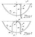
- 0016. Referring now to the drawings with greater particularity, there is shown in Fig. 1 a
lamp 10 that comprises aconcave reflector 12 arrayed about anaxis 14 and having acircumferential rim 16. AnLED light source 18 is mounted upon asupport 20 that is associated with theconcave reflector 12, thesupport 20 having aleg 22 that is fixed in theconcave reflector 12, for example by a press-fit of theleg 22 in aslot 22a. TheLED light source 18 can be of any suitable style, such as a side emitting LED and the emitted color can be suitable for the lamp's purpose, for example, red emitting for a tail light or stop light or white for a headlight. More than one LED can be employed if desired. If only one LED is used it is preferably aligned along theaxis 14. - 0017. An alternate embodiment is shown in Fig. 2 wherein the
support 20 is U-shaped with abight 24 andlegs LED light source 18 is mounted in thebight 24 of the U-shaped support in a manner to direct light directly toward theconcave reflector 12 and thelegs concave reflector 12 in any suitable manner, for example by being press-fitted intoslots 22a and 26a.. - 0018. In Fig. 3 the
lamp 10 similarly comprises aconcave reflector 12 arrayed about anaxis 14 and having acircumferential rim 16. However, in this instance anLED light source 18 is mounted upon asupport 20a that is V-shaped and associated with theconcave reflector 12 by being arrayed along the circumferential rim with theLED light source 18 directing light toward the concave reflector from the edge instead of from the center. - 0019. The
circumferential rim 16 has amounting groove 28 that can be in the form of a V-shaped trough as shown in Fig. 3 or as a series of openings, only one of which is shown, in Fig. 4. The V-shaped trough can be continuous circumferentially or be formed as one or more discrete areas, depending upon the number of LEDs to be used. Thegroove 28 is provided with asupport retainer 30 that can be in the form of an extendinglip 30a as shown in Fig. 3. In this case the V-shaped support 20a can have an original configuration 20b and can be compressed to snap-fit into the housing. Alternatively, an angled surface 30b as shown in Fig. 4 can be provided. - 0020. The
support 20 is thermally conductive to remove operational heat from the LED or LEDs and is also provided with the circuitry 32 (shown diagrammatically) necessary to operate the lamp in its chosen environment. - 0021. When mounted on or near the
rim 16 theLED light source 18 is mounted at an angle θ relative to theaxis 14 to insure proper alignment. While the angle will, of course, be dependent upon the curvature of the reflector and the particular LED being used, with a parabolic reflector typical of those used for automotive functions, an angle of approximately 30 degrees will provide good results for directing light from theLED 18 onto the surface of thereflector 12. - 0022. As a result the
LEDs 18 are widely spread around the reflector rim providing improved heat dispersion while concentrating the emitted light on the reflector. No holes are formed in the center of the reflector so no shadows or gaps are created in the resulting beam pattern. The snap fit assembly assures proper positioning of the LEDs - 0023. While there have been shown and described what are present considered to be the preferred embodiments of the invention, it will be apparent to those skilled in the art that various changes and modifications can be made herein without departing from the scope of the invention as defined by the appended claims.
Claims (13)
- A lamp comprising:a concave reflector arrayed about an axis and having a circumferential rim;an LED light source mounted upon a support that is associated with said concave reflector, said support being arrayed along said circumferential rim and directing light toward said concave reflector.
- A lamp comprising:a concave reflector arrayed about an axis and having a circumferential rim;an LED light source mounted upon a support that is associated with said concave reflector, said support having an end that is fixed in said concave reflector.
- The lamp of Claim 2 wherein said support is U-shaped, said LED light source is mounted in the bight of said U-shaped support in a manner to direct light directly toward said concave reflector and the legs of said U-shaped support are fixed in said concave reflector.
- The lamp of Claim 1 wherein said circumferential rim includes a mounting groove that has a support retainer.
- The lamp of Claim 4 wherein said support is engaged with said mounting groove and said support retainer.
- The lamp of Claim 1 wherein said support includes thermally conductive material to carry away and excess heat generated by said LED light source when said LED light source is operating.
- The lamp of Claim 6 wherein said support includes electrical circuitry for operating said LED light source.
- The lamp of Claim 2 wherein said support includes thermally conductive material to carry away and excess heat generated by said LED light source when said LED light source is operating.
- The lamp of Claim 3 wherein said support includes thermally conductive material to carry away any excess heat generated by said LED light source when said LED light source is operating.
- The lamp of Claim 1 wherein said support includes electrical circuitry for operating said LED light source.
- The lamp of Claim 1 wherein said support is maintained with said rim by a tensioned force.
- The lamp of Claim 1 wherein said reflector has a center portion located about said axis and said center portion is aperture-free.
- The lamp of Claim 2 wherein said reflector has a center portion located about said axis and said center portion is aperture-free.
Applications Claiming Priority (2)
| Application Number | Priority Date | Filing Date | Title |
|---|---|---|---|
| US58814304P | 2004-07-16 | 2004-07-16 | |
| US11/121,493 US20060013004A1 (en) | 2004-07-16 | 2005-05-03 | LED sideward emitting lamp |
Publications (2)
| Publication Number | Publication Date |
|---|---|
| EP1617131A2 true EP1617131A2 (en) | 2006-01-18 |
| EP1617131A3 EP1617131A3 (en) | 2006-09-27 |
Family
ID=35141705
Family Applications (1)
| Application Number | Title | Priority Date | Filing Date |
|---|---|---|---|
| EP05015269A Withdrawn EP1617131A3 (en) | 2004-07-16 | 2005-07-14 | LED sideward emitting lamp |
Country Status (4)
| Country | Link |
|---|---|
| US (1) | US20060013004A1 (en) |
| EP (1) | EP1617131A3 (en) |
| JP (1) | JP2006032345A (en) |
| CA (1) | CA2509184A1 (en) |
Cited By (3)
| Publication number | Priority date | Publication date | Assignee | Title |
|---|---|---|---|---|
| FR2942527A1 (en) * | 2009-02-25 | 2010-08-27 | Cooper Securite Sas | Domestic lighting device for use in wall of ceiling, has plate with active face whose border extends above reflecting part of reflector to maintain LED opposite to reflecting part where thermal energy produced by LED is dissipated |
| EP2287524A1 (en) * | 2009-08-20 | 2011-02-23 | Graviton Lite Limited | Lighting apparatus and a method of fabrication |
| EP2846079A1 (en) * | 2013-09-06 | 2015-03-11 | Valeo Vision | Lighting module for an illumination and/or signalling device |
Families Citing this family (3)
| Publication number | Priority date | Publication date | Assignee | Title |
|---|---|---|---|---|
| TW201120376A (en) * | 2009-12-11 | 2011-06-16 | Power Light Tech Co Ltd | Reflection type light-emitting assembly |
| JP6881881B2 (en) * | 2015-02-25 | 2021-06-02 | リン、ジャオフイ | Surgical lighting and replacement bulbs for surgical lighting |
| US11480313B2 (en) | 2019-05-17 | 2022-10-25 | North American Lighting, Inc. | Vehicle lamp |
Citations (8)
| Publication number | Priority date | Publication date | Assignee | Title |
|---|---|---|---|---|
| US5136483A (en) | 1989-09-08 | 1992-08-04 | Schoeniger Karl Heinz | Illuminating device |
| US5471371A (en) | 1993-01-08 | 1995-11-28 | Ford Motor Company | High efficiency illuminator |
| US6238073B1 (en) | 1998-03-13 | 2001-05-29 | Stanley Electric Co., Ltd. | Vehicle signal lighting unit |
| US6474852B1 (en) | 1999-10-21 | 2002-11-05 | Ichikoh Industries, Ltd. | Small light-source module and light-source unit |
| US6585402B2 (en) | 2000-11-16 | 2003-07-01 | Ichikoh Industries, Ltd. | Vehicle lamp |
| US6641287B2 (en) | 2001-04-11 | 2003-11-04 | Toyoda Gosei Co., Ltd. | Reflective type light-emitting diode |
| US6672741B1 (en) | 2002-08-16 | 2004-01-06 | Tony Chunlung Young | Light emitting diode reflector |
| US6840652B1 (en) | 2001-07-31 | 2005-01-11 | Hi-Lite Safety Systems, L.C. | Lighting enhanced by magnified reflective surfaces |
Family Cites Families (11)
| Publication number | Priority date | Publication date | Assignee | Title |
|---|---|---|---|---|
| US5924785A (en) * | 1997-05-21 | 1999-07-20 | Zhang; Lu Xin | Light source arrangement |
| JP2960928B1 (en) * | 1998-07-24 | 1999-10-12 | スタンレー電気株式会社 | Signal lights for vehicles |
| EP1113506A3 (en) * | 1999-12-28 | 2005-03-16 | Toyoda Gosei Co., Ltd. | Light emitting diode |
| EP1146572A3 (en) * | 2000-03-14 | 2005-03-23 | Toyoda Gosei Co., Ltd. | Light source device |
| CN2458485Y (en) * | 2000-11-16 | 2001-11-07 | 上海嘉利莱实业有限公司 | LED lighting module |
| US6578998B2 (en) * | 2001-03-21 | 2003-06-17 | A L Lightech, Inc. | Light source arrangement |
| JP2003092006A (en) * | 2001-09-19 | 2003-03-28 | Yamada Shomei Kk | Lighting equipment and illumination light |
| DE10149273A1 (en) * | 2001-10-05 | 2003-04-17 | Reitter & Schefenacker Gmbh | Reflector for a light, such as a rear light, a headlight or an interior light of a motor vehicle |
| FR2831647B1 (en) * | 2001-10-26 | 2004-04-16 | Peugeot Citroen Automobiles Sa | MOTOR VEHICLE SIGNALING LIGHT FOR INDIRECT LIGHT BEAMS BROADCAST |
| EP1631769B1 (en) * | 2003-06-10 | 2010-09-22 | Illumination Management Solutions, Inc. | An improved led flashlight |
| US20050146890A1 (en) * | 2004-01-05 | 2005-07-07 | Shih-Hsiung Wu | Vehicle light with a large illumination area |
-
2005
- 2005-05-03 US US11/121,493 patent/US20060013004A1/en not_active Abandoned
- 2005-06-03 CA CA002509184A patent/CA2509184A1/en not_active Abandoned
- 2005-07-14 JP JP2005205489A patent/JP2006032345A/en active Pending
- 2005-07-14 EP EP05015269A patent/EP1617131A3/en not_active Withdrawn
Patent Citations (8)
| Publication number | Priority date | Publication date | Assignee | Title |
|---|---|---|---|---|
| US5136483A (en) | 1989-09-08 | 1992-08-04 | Schoeniger Karl Heinz | Illuminating device |
| US5471371A (en) | 1993-01-08 | 1995-11-28 | Ford Motor Company | High efficiency illuminator |
| US6238073B1 (en) | 1998-03-13 | 2001-05-29 | Stanley Electric Co., Ltd. | Vehicle signal lighting unit |
| US6474852B1 (en) | 1999-10-21 | 2002-11-05 | Ichikoh Industries, Ltd. | Small light-source module and light-source unit |
| US6585402B2 (en) | 2000-11-16 | 2003-07-01 | Ichikoh Industries, Ltd. | Vehicle lamp |
| US6641287B2 (en) | 2001-04-11 | 2003-11-04 | Toyoda Gosei Co., Ltd. | Reflective type light-emitting diode |
| US6840652B1 (en) | 2001-07-31 | 2005-01-11 | Hi-Lite Safety Systems, L.C. | Lighting enhanced by magnified reflective surfaces |
| US6672741B1 (en) | 2002-08-16 | 2004-01-06 | Tony Chunlung Young | Light emitting diode reflector |
Cited By (5)
| Publication number | Priority date | Publication date | Assignee | Title |
|---|---|---|---|---|
| FR2942527A1 (en) * | 2009-02-25 | 2010-08-27 | Cooper Securite Sas | Domestic lighting device for use in wall of ceiling, has plate with active face whose border extends above reflecting part of reflector to maintain LED opposite to reflecting part where thermal energy produced by LED is dissipated |
| EP2287524A1 (en) * | 2009-08-20 | 2011-02-23 | Graviton Lite Limited | Lighting apparatus and a method of fabrication |
| US8366296B2 (en) | 2009-08-20 | 2013-02-05 | Graviton Lite Limited | Lighting apparatus for illuminating accessible areas |
| EP2846079A1 (en) * | 2013-09-06 | 2015-03-11 | Valeo Vision | Lighting module for an illumination and/or signalling device |
| FR3010488A1 (en) * | 2013-09-06 | 2015-03-13 | Valeo Vision | LUMINOUS MODULE FOR LIGHTING AND / OR SIGNALING DEVICE |
Also Published As
| Publication number | Publication date |
|---|---|
| CA2509184A1 (en) | 2006-01-16 |
| JP2006032345A (en) | 2006-02-02 |
| EP1617131A3 (en) | 2006-09-27 |
| US20060013004A1 (en) | 2006-01-19 |
Similar Documents
| Publication | Publication Date | Title |
|---|---|---|
| US7237927B2 (en) | Light emitting diode lamp with conically focused light guides | |
| US7325955B2 (en) | Apparatus and method for mounting and adjusting LED headlamps | |
| US6414801B1 (en) | Catadioptric light emitting diode assembly | |
| US7131760B2 (en) | LED luminaire with thermally conductive support | |
| EP1607676B1 (en) | LED lamp with light pipes | |
| US7186010B2 (en) | LED lamp and lamp/reflector assembly | |
| US7275839B2 (en) | Three color LED bulb | |
| US7110656B2 (en) | LED bulb | |
| US7092612B1 (en) | LED bulb | |
| EP1696172B1 (en) | Colored headlamp | |
| US20070070645A1 (en) | LED lamp with direct optical coupling in axial arrangement | |
| EP1617131A2 (en) | LED sideward emitting lamp | |
| KR20080046689A (en) | Led headlamp system | |
| US20080025037A1 (en) | LED headlamp | |
| US9163803B2 (en) | Hybrid driving light | |
| US7040792B2 (en) | Light-emitting diode module for a vehicle headlamp, and a vehicle headlamp | |
| US20060109654A1 (en) | Stem mount for light emitting diode | |
| JP4627239B2 (en) | lighting equipment | |
| EP1617135A2 (en) | Molded-in light emitting diode light source | |
| US7052166B2 (en) | Light emitting diode optics | |
| EP1617132A2 (en) | Stem mount for light emitting diode | |
| CN1721760A (en) | LED sideward emitting lamp | |
| CN219530639U (en) | Lighting device, motor vehicle headlight and motor vehicle | |
| JP3089316U (en) | LED bulb for automobile | |
| KR20020088913A (en) | Projection Head Lamp having Vehicle's Width Lamp |
Legal Events
| Date | Code | Title | Description |
|---|---|---|---|
| PUAI | Public reference made under article 153(3) epc to a published international application that has entered the european phase |
Free format text: ORIGINAL CODE: 0009012 |
|
| AK | Designated contracting states |
Kind code of ref document: A2 Designated state(s): AT BE BG CH CY CZ DE DK EE ES FI FR GB GR HU IE IS IT LI LT LU LV MC NL PL PT RO SE SI SK TR |
|
| AX | Request for extension of the european patent |
Extension state: AL BA HR MK YU |
|
| PUAL | Search report despatched |
Free format text: ORIGINAL CODE: 0009013 |
|
| AK | Designated contracting states |
Kind code of ref document: A3 Designated state(s): AT BE BG CH CY CZ DE DK EE ES FI FR GB GR HU IE IS IT LI LT LU LV MC NL PL PT RO SE SI SK TR |
|
| AX | Request for extension of the european patent |
Extension state: AL BA HR MK YU |
|
| STAA | Information on the status of an ep patent application or granted ep patent |
Free format text: STATUS: THE APPLICATION HAS BEEN WITHDRAWN |
|
| 18W | Application withdrawn |
Effective date: 20070202 |