EP1621857A2 - Device for the determination of the colour value of transparent objects, in particular teeth - Google Patents
Device for the determination of the colour value of transparent objects, in particular teeth Download PDFInfo
- Publication number
- EP1621857A2 EP1621857A2 EP05405406A EP05405406A EP1621857A2 EP 1621857 A2 EP1621857 A2 EP 1621857A2 EP 05405406 A EP05405406 A EP 05405406A EP 05405406 A EP05405406 A EP 05405406A EP 1621857 A2 EP1621857 A2 EP 1621857A2
- Authority
- EP
- European Patent Office
- Prior art keywords
- light
- emitting diode
- measurement object
- wavelength ranges
- emitting diodes
- Prior art date
- Legal status (The legal status is an assumption and is not a legal conclusion. Google has not performed a legal analysis and makes no representation as to the accuracy of the status listed.)
- Withdrawn
Links
- 238000000034 method Methods 0.000 claims abstract description 13
- 239000000835 fiber Substances 0.000 claims abstract description 12
- 239000002184 metal Substances 0.000 claims abstract description 3
- 238000005259 measurement Methods 0.000 claims description 60
- 238000005286 illumination Methods 0.000 claims description 19
- 238000001514 detection method Methods 0.000 claims description 16
- 239000000523 sample Substances 0.000 claims description 15
- 239000013307 optical fiber Substances 0.000 claims description 13
- 230000005855 radiation Effects 0.000 claims description 9
- 239000011521 glass Substances 0.000 claims description 6
- 230000003287 optical effect Effects 0.000 claims description 5
- 230000010287 polarization Effects 0.000 claims description 4
- 239000003086 colorant Substances 0.000 claims description 3
- 238000005516 engineering process Methods 0.000 claims description 3
- 238000012360 testing method Methods 0.000 claims description 3
- 239000011248 coating agent Substances 0.000 claims description 2
- 238000000576 coating method Methods 0.000 claims description 2
- 230000001629 suppression Effects 0.000 claims 1
- 230000004907 flux Effects 0.000 description 5
- 238000011156 evaluation Methods 0.000 description 3
- 238000004737 colorimetric analysis Methods 0.000 description 2
- 238000012937 correction Methods 0.000 description 2
- 230000001419 dependent effect Effects 0.000 description 2
- 230000004913 activation Effects 0.000 description 1
- 230000008901 benefit Effects 0.000 description 1
- 230000002457 bidirectional effect Effects 0.000 description 1
- 238000005266 casting Methods 0.000 description 1
- 230000008859 change Effects 0.000 description 1
- 239000004020 conductor Substances 0.000 description 1
- 238000011161 development Methods 0.000 description 1
- 230000018109 developmental process Effects 0.000 description 1
- 230000000694 effects Effects 0.000 description 1
- 239000003822 epoxy resin Substances 0.000 description 1
- 238000000265 homogenisation Methods 0.000 description 1
- 230000001771 impaired effect Effects 0.000 description 1
- 239000000463 material Substances 0.000 description 1
- 229920003023 plastic Polymers 0.000 description 1
- 229920000647 polyepoxide Polymers 0.000 description 1
- 229920001296 polysiloxane Polymers 0.000 description 1
- 230000008569 process Effects 0.000 description 1
- 238000011144 upstream manufacturing Methods 0.000 description 1
Images


Classifications
-
- G—PHYSICS
- G01—MEASURING; TESTING
- G01N—INVESTIGATING OR ANALYSING MATERIALS BY DETERMINING THEIR CHEMICAL OR PHYSICAL PROPERTIES
- G01N21/00—Investigating or analysing materials by the use of optical means, i.e. using sub-millimetre waves, infrared, visible or ultraviolet light
- G01N21/17—Systems in which incident light is modified in accordance with the properties of the material investigated
- G01N21/25—Colour; Spectral properties, i.e. comparison of effect of material on the light at two or more different wavelengths or wavelength bands
- G01N21/255—Details, e.g. use of specially adapted sources, lighting or optical systems
-
- G—PHYSICS
- G01—MEASURING; TESTING
- G01J—MEASUREMENT OF INTENSITY, VELOCITY, SPECTRAL CONTENT, POLARISATION, PHASE OR PULSE CHARACTERISTICS OF INFRARED, VISIBLE OR ULTRAVIOLET LIGHT; COLORIMETRY; RADIATION PYROMETRY
- G01J3/00—Spectrometry; Spectrophotometry; Monochromators; Measuring colours
- G01J3/02—Details
- G01J3/10—Arrangements of light sources specially adapted for spectrometry or colorimetry
-
- G—PHYSICS
- G01—MEASURING; TESTING
- G01J—MEASUREMENT OF INTENSITY, VELOCITY, SPECTRAL CONTENT, POLARISATION, PHASE OR PULSE CHARACTERISTICS OF INFRARED, VISIBLE OR ULTRAVIOLET LIGHT; COLORIMETRY; RADIATION PYROMETRY
- G01J3/00—Spectrometry; Spectrophotometry; Monochromators; Measuring colours
- G01J3/46—Measurement of colour; Colour measuring devices, e.g. colorimeters
- G01J3/50—Measurement of colour; Colour measuring devices, e.g. colorimeters using electric radiation detectors
Definitions
- the invention relates to a device for determining the color valence of objects according to the preamble of claim 1 and to a method for operating the device according to claim 18.
- a method and a device for determining the color valence of translucent objects is known.
- the object to be measured is illuminated with light in different wavelength ranges, or the light reflected by the object to be measured is divided into different wavelength ranges with an image sensor prior to detection.
- a conventional lamp is used as the light source.
- the lamp is preferably followed by a concave mirror provided with a diffraction grating. By rotating the concave mirror, the wavelength range coupled into a subsequent fiber optic bundle is changed.
- two image sensors are used, wherein one image sensor is used to visualize the measurement object and the other image sensor is used to determine the colorimetric data of the measurement object.
- the object of the invention is therefore to form the defined in the preamble of claim 1 device such that it is inexpensive, lightweight and portable, the electrical power consumption should be reduced so far that they can be operated by means of batteries or rechargeable batteries.
- the illumination device comprises a plurality of sequentially controllable light-emitting diodes which emit light in different wavelength ranges, we created the fundamental requirement to operate the device autonomously, ie independently of the mains.
- light-emitting diodes have an only slightly better efficiency than incandescent lamps, the fact that, unlike incandescent lamps, that the total emitted light output of the corresponding wavelength range can be used for the measurement, the optical efficiency is about 20 times better, as a result of which Power consumption is ultimately much lower and is allowed to feed the device by means of batteries or rechargeable batteries.
- the use of light-emitting diodes instead of a conventional light source with downstream, electric motor-operated concave mirror has the further advantage that the device is much lighter and more compact and also can be produced more cheaply.
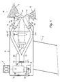
- the schematically illustrated device according to FIG. 1 consists essentially of an illumination device 1, a detection device 2, a microprocessor-controlled control and evaluation electronics 3, a display 4 and a battery 5.
- the said elements are accommodated in an upper part formed as a probe head 6.
- the probe head 6 is provided on the front with a front part 8, which comes to rest on the measurement object M.
- the entire device is designed as an autonomous, portable device and provided with a handle 7. As the measurement object M, areas of the lower or upper jaw 9, 10 together with two teeth 11, 12 are shown.
- the lighting device 1 has, as the actual light source, a light-emitting diode arrangement 14 with a multiplicity of light-emitting diodes 15, of which only three of them are shown schematically.
- the light emitting diodes 14 are arranged on a printed circuit board 16.
- the light-emitting diode arrangement 14 has eight different types of light-emitting diodes which emit light in eight different wavelength ranges.
- the lighting device 1 further comprises an optical fiber bundle 17 into which the light emitted by the light emitting diodes 15 is coupled.
- the optical fiber bundle 17 is divided into two Y-shaped strands 17a, 17b.
- the two strands 17a, 17b of the optical fiber bundle 17 are split at the ends into individual, preferably annularly arranged fibers in order to obtain the most homogeneous possible illumination of the object to be measured M.
- the two optical fiber strands 17a, 17b are followed by lenses 19, 20, which additionally contribute to a uniform illumination of the measurement object M.
- lenses 19, 20 On the light guide fiber strands 17a, 17b downstream lenses 19, 20 follow polarizers 21, 22, which are also shown only schematically.
- a reference mark 23 can be seen, the meaning of which will also be discussed in more detail below.
- a fiber optic fiber bundle 17 for example, a glass rod can be used.
- the detection device 2 is provided with a detection sensor 25 which serves to detect the light reflected by the measurement object M.
- a detection sensor 25 is preferably a black and white CCD chip (Charge Coupled Device) or a black and white CMOS image sensor is used.
- the detection sensor 25 is connected to the electronics 3 via a data line 28. In order to direct the light reflected by the measurement object M to the detection sensor 2, this is preceded by a lens 26.
- a polarizer 27 is arranged, which are tuned to the optical fiber strands 17a, 17b downstream polarizers 20, 22 in such a way that it passes the light emitted by the object to be measured M, while acting as a filter for from the surface of the object to be measured M.
- the polarizer (27) arranged upstream of the detection sensor 25 has a polarization direction rotated by 90 ° relative to the polarizers 20, 22 connected downstream of the optical fiber strands 17a, 17b, or at most no twisted polarization direction, wherein In this case, the polarization is twisted with one or more additional circulator polarizers.
- the device is further provided with a plug connection 31, which is connected via a data line 30 to the electronics 3. Via this plug connection 31, bidirectional data can be transmitted and exchanged. In particular, the measured colorimetric data can be read out via the plug connection 31.
- a plug 33 can be seen, which is connected via a line 32 to the battery and serves to connect a charger. It is understood that the term "battery" is representative of both conventional batteries and all types of rechargeable batteries.
- the light-emitting diode arrangement 14 has eight different types of light-emitting diode which emit visible light in the sense of a monochromator in eight different, narrowband wavelength ranges between approximately 430 and 650 nanometers, wherein the wavelength ranges should be distributed as evenly as possible over the stated range.
- a different number of types of light-emitting diode can be used instead of eight different types of light-emitting diode.
- the number of types of LEDs used depends i.a. their availability and the requirements of colorimetry. Of course, should one of the LED's be available with other or additional wavelength ranges, then the total visible light range between about 380 and 730 nanometers could be covered by a corresponding number of LED types.
- the LEDs 15 are preferably arranged by means of chip-on-board technology annular on the circuit board 16 and electrically connected by means of bonding technology with the corresponding conductor or contact surface.
- a metal core board is used.
- the individual LEDs are mounted and bonded without housing on the circuit board, wherein the entire light emitting diode array by means of a casting material, for example, clear epoxy resin, poured and coupled by means of another mass, such as a permanently elastic silicone gel, optically to the optical fiber bundle 17.
- the diameter of the fiber optic fiber bundle 17 is tuned to the diameter of the light emitting diode array 14 and is less than ten millimeters in the present case.
- the individual high-performance light-emitting diodes are arranged in the center, while the less powerful light-emitting diodes are arranged grouped on the periphery.
- the illumination device 1 is advantageously designed such that not only the measurement object 7 itself, but also the adjacent regions of the upper and lower jaw 6a, 6b are illuminated. Due to the average size of a tooth, an area of at least 10x15 mm, preferably at least 16x22mm, should be illuminated. Due to the translucency of the measurement object, it is important in any case that the illuminated area is larger than the area detected for the determination of the color valence of the measurement object M, ie larger than a single tooth.
- a measurement without illumination is performed first.
- the measurement value present at the detection sensor 25 at this time thus corresponds to the light coupled in from outside into the measurement object M or the detection device 2 (ambient light). So that in the subsequent measurements carried out with illumination, the measured value present at the detection sensor 25 is not falsified by the light coupled in from the outside, this dark value is in each case subtracted from the actual measured value.
- eight measurements are carried out with illumination by the respective light-emitting diode or the respective light-emitting diode group is sequentially driven / so that the measurement object M is illuminated in succession with visible light in eight different wavelength ranges.
- the measured value applied to the detection sensor 25 is detected and stored.
- the respective LED types are energized only for a very short time with power, but with a multiple of the rated current.
- the LEDs are energized only for about 20 milliseconds, but with five to ten times the nominal current specified by the manufacturer. In this way, the desired light intensity can be achieved without the light-emitting diodes 15 being damaged. Since the luminous flux emitted by the light-emitting diodes 15 is subject to or may be subject to certain fluctuations, the measurement of the reference mark 23 will occur with each measurement measured on the detection sensor 25 reflected luminous flux.
- the emitted luminous flux can be calculated and, if necessary, a correction of the measured values can be carried out.
- the correction values are calculated as follows: If a modified light value is measured on the reference surface of the respective reference mark 23, the measurement data are corrected by the factor of the change on the reference surface.
- two reference marks are preferably used. The reference marks are arranged as close as possible to the front part 8 of the probe head 6. In order not to influence the size of the image to be evaluated by the two reference marks in a sustainable and negative manner, the two reference marks are preferably positioned such that they cover only the corner regions of the image to be acquired.
- the measurement object M is displayed visually on the display 4.
- the measurement object M is illuminated sequentially and in very short time intervals in the wavelength ranges of the three primary colors red, green and blue.
- those three types of light emitting diode are sequentially driven, which emit light in the next three wavelengths closest wavelength ranges. From these three primary colors can then computationally a color image assembled and reproduced the measurement object in color on the display, as shown in suggestion.
- the probe head of the device must be aligned with respect to the measurement object such that the optical axis of the device runs exactly perpendicular to the surface of the measurement object.
- the measurement object is a tooth in the mouth of a patient
- the above-mentioned exact alignment of the optical axis is not so easy to accomplish because the operator can not see the tooth during the measurement process.
- Another difficulty is that the teeth are often arranged somewhat obliquely in the mouth of a patient. Since the probe head of the device according to the invention is handled manually, i.
- this problem is taken into account in that a possible angular error in positioning the Probe head 6 is visualized so that the position or orientation of the probe head 6 of the device can be easily corrected before the measurement is performed.
- an extended illumination device is provided in this further exemplary embodiment, of which the essential parts are shown schematically in FIG. 3 in order to project a line pattern onto the surface of the measurement object M at an angle of 45 °. As can be seen from FIG. 2, the parallel lines 34 of the line pattern run vertically on the surface of the measuring object 35.
- the resulting line pattern 34a is on the surface of the measuring object 35 relative to the vertical line pattern 34 generated by a correctly placed probe head 6 , inclined.
- the line pattern 34 or 34a can be made visible on the display 4 (FIG. 1) with the aid of the sensor 26 and the sensor 25. In this way, the operator can correct the position and orientation of the probe head 6.
- the image of the line pattern received by the sensor 25 can be further processed by the control and evaluation unit 3 to calculate the angle error based on the course of the lines 34a projected on the surface of the measurement object.
- the deviation of the course of the lines 34a from the horizontal direction is directly proportional to the deviation of the optical axis of the probe head from the desired direction.
- the control and evaluation unit 3 can provide a statement that allows the operator to correct the position or orientation of the probe head 6.
- an illumination device 1 is already present, which makes it possible to determine the color valence of the measurement object and to illuminate the measurement object at an angle of 45 °.
- this illumination device 1 makes sense to use at least parts of this illumination device 1 to additionally project the line pattern 34 onto the measurement object 35.
- the line pattern 34 is e.g. generated in the range of infrared radiation.
- An alternative illumination device is shown in a schematic side view in FIG. 6 and in a schematic view from above in FIG. 7. It comprises a homogenizer 41, eg a glass rod or a fiber optic bundle, a first deflecting mirror 42, a second deflecting mirror 43, a first lens 44, a second lens 45, a slit diaphragm 46 and a filter 47.
- the radiation path is indicated by the line 48, and the dot-dash line in Fig. 7 symbolizes the plane of symmetry. It is understood that in addition there are the parts and elements required for the measurement of the color valence, which were discussed at the beginning in connection with FIG. 1,
- the illumination device according to FIGS. 6 and 7 shows the following differences:
- the light emitting diode array 14 (not shown in FIGS. 6 and 7) additionally includes at least one other light emitting diode that emits light in the near infrared region, i. with a wavelength of about 850 nm.
- the light which emit this further or this further light emitting diode (s) is likewise coupled into the glass rod or the optical fiber bundle 41.
- a further measurement with illumination by the additional IR light emitting diode or the additional IR light emitting diodes is performed.
- the light fiber bundle 41 is in this embodiment not divided into two strands 17a, 17b as in the embodiment of FIG. 1. Rather, the light beam leaving the optical fiber bundle 41 is deflected by the first deflecting mirror 42 by 90 °.
- the front of the deflecting mirror 42 is provided with a so-called cold light mirror layer. Such a layer acts as a mirror for the visible light, but is transparent to IR light.
- the back of the mirror 42 is provided with a line pattern which reflects infrared radiation.
- the line pattern is projected through the front-side coating of the mirror 42, which is transparent to IR, via the second deflection mirror 43 and the lens 45 onto the measurement object 35.
- the line pattern is aligned so that it extends on the surface of the measurement object in the vertical direction, as indicated in FIGS. 2 and 5.
- an aperture / filter combination 46, 47 is inserted in the light path 48. This is necessary because the reflective line pattern on the back of the mirror 42 is not optically in the right place, resulting in a blurred image of the line pattern on the surface of the device under test.
- the slit diaphragm 46 Through the slit diaphragm 46, the depth of field is increased so far that a sharp image of the line pattern on the surface of the measurement object is ensured.
- slit diaphragm 46 is designed to have no effect on visible light, i. is transparent in order to avoid light losses in the actual colorimetric measurement. This is in turn achieved by a so-called cold light mirror layer on the surface of the slit, but has a central slot.
- visible light can pass unhindered through the aperture / filter combination 45, 46, while the infrared light can only pass through the slot.
- the cold mirror layer is not perfect, then this is not bad or harmless to the measurement because these tracks would be completely blurred.
- the illumination device according to FIGS. 6 and 7 is generally symmetrical with respect to the line 49.
- the projection of the line pattern onto the surface of the measuring object 35 preferably takes place only from one side.
- the arrangement symmetrical with the arrangement shown in FIG. 7 is slightly different.
- the first deflecting mirror 42 has no reflective layer in the form of a line pattern on its rear side. Therefore, no line pattern is projected onto the surface of the measuring object 35 from that side.
- the arrangement 45, 46 is a cold mirror without slot and thus not transparent to infrared light. Consequently, light having a wavelength in the infrared region only reaches the surface of the measuring object 35 from one side, while visible light is projected from both sides onto the surface of the measuring object.
Abstract
Description
Die Erfindung betrifft eine Vorrichtung zur Bestimmung der Farbvalenz von Objekten nach dem Oberbegriff des Anspruchs 1 sowie ein Verfahren zum Betrieb der Vorrichtung nach dem Anspruch 18.The invention relates to a device for determining the color valence of objects according to the preamble of
Aus der EP-A-0 928 957 ist ein Verfahren sowie eine Vorrichtung zur Bestimmung der Farbvalenz von transluzenten Objekten bekannt. Zur Bestimmung der Farbvalenz des transluzenten Messobjekts wird das Messobjekt mit Licht in unterschiedlichen Wellenlängenbereichen beleuchtet oder das vom Messobjekt reflektierte Licht vor der Erfassung mit einem Bildsensor in unterschiedliche Wellenlängenbereiche aufgeteilt. Als Lichtquelle wird eine herkömmliche Lampe eingesetzt. Zum Erzeugen der unterschiedlichen Wellenlängenbereiche wird der Lampe vorzugsweise ein mit einem Beugungsgitter versehener Hohlspiegel nachgeschaltet. Durch Verdrehen des Hohlspiegels wird der in ein nachfolgendes Lichtleiterfaserbündel eingekoppelte Wellenlängenbereich verändert. Vorzugsweise werden zwei Bildsensoren eingesetzt, wobei der eine Bildsensor zum Visualisieren des Messobjekts und der andere Bildsensor zum Ermitteln der farbmetrischen Daten des Messobjekts verwendet wird. Obwohl sich das in dieser Schrift beschriebene Verfahren sowie die zugehörige Vorrichtung bewährt haben, wäre es wünschenswert, wenn die Vorrichtung portabel und handlicher wäre und ausserdem kostengünstiger hergestellt werden könnte.From EP-A-0 928 957 a method and a device for determining the color valence of translucent objects is known. To determine the color valence of the translucent object to be measured, the object to be measured is illuminated with light in different wavelength ranges, or the light reflected by the object to be measured is divided into different wavelength ranges with an image sensor prior to detection. As the light source, a conventional lamp is used. To produce the different wavelength ranges, the lamp is preferably followed by a concave mirror provided with a diffraction grating. By rotating the concave mirror, the wavelength range coupled into a subsequent fiber optic bundle is changed. Preferably, two image sensors are used, wherein one image sensor is used to visualize the measurement object and the other image sensor is used to determine the colorimetric data of the measurement object. Although the method described in this document and the associated device have proven successful, it would be desirable if the device were portable and handy and could also be produced more cheaply.
Die Aufgabe der Erfindung besteht nun darin, die im Oberbegriff des Anspruchs 1 definierte Vorrichtung derart auszubilden, dass sie kostengünstig, leicht und portabel ist, wobei die elektrische Leistungsaufnahme soweit reduziert werden soll, dass sie mittels Batterien oder Akkus betrieben werden kann.The object of the invention is therefore to form the defined in the preamble of
Diese Aufgabe wird mit einer Vorrichtung gelöst, welche mit den Kennzeichen des Anspruchs 1 definierten Merkmalen versehen ist.This object is achieved with a device which is provided with the features of
Indem die Beleuchtungseinrichtung eine Vielzahl von sequentiell ansteuerbaren Leuchtdioden umfasst, welche Licht in unterschiedlichen Wellenlängenbereichen emittieren, wir die grundsätzliche Voraussetzung geschaffen, die Vorrichtung autonom, d.h. netzunabhängig zu betreiben. Auch wenn Leuchtdioden einen gegenüber Glühlampen nur geringfügig besseren Wirkungsgrad haben, wird dadurch, dass im Gegensatz zu Glühlampen, die gesamte emittierte Lichtleistung des entsprechenden Wellenlängenbereichs zur Messung verwendet werden kann, der optische Wirkungsgrad ca. 20 mal besser, wodurch die Leistungsaufnahme letztlich wesentlich geringer ist und ermöglicht wird, die Vorrichtung mittels Batterien oder Akkus zu speisen. Die Verwendung von Leuchtdioden anstelle einer herkömmlichen Lichtquelle mit nachgeschaltetem, elektromotorisch betriebenem Hohlspiegel hat den weiteren Vorteil, dass die Vorrichtung wesentlich leichter und kompakter ausfällt und zudem kostengünstiger hergestellt werden kann.By the illumination device comprises a plurality of sequentially controllable light-emitting diodes which emit light in different wavelength ranges, we created the fundamental requirement to operate the device autonomously, ie independently of the mains. Although light-emitting diodes have an only slightly better efficiency than incandescent lamps, the fact that, unlike incandescent lamps, that the total emitted light output of the corresponding wavelength range can be used for the measurement, the optical efficiency is about 20 times better, as a result of which Power consumption is ultimately much lower and is allowed to feed the device by means of batteries or rechargeable batteries. The use of light-emitting diodes instead of a conventional light source with downstream, electric motor-operated concave mirror has the further advantage that the device is much lighter and more compact and also can be produced more cheaply.
Bevorzugte Ausführungsarten der Vorrichtung in den abhängigen Ansprüchen 2 bis 17 umschrieben.Preferred embodiments of the device in the
Im Anspruch 18 wird zudem ein Verfahren zum Betrieb der Vorrichtung beansprucht. Die abhängigen Ansprüche 19 bis 23 beschreiben bevorzugte Weiterbildungen des Verfahrens.In claim 18, a method for operating the device is also claimed. The dependent claims 19 to 23 describe preferred developments of the method.
Bevorzugte Ausführungsbeispiele der erfindungsgemässen Vorrichtung werden nachfolgend anhand der Zeichnungen näher erläutert. In den Zeichnungen zeigen:
- Fig. 1 eine schematische Seitenansicht der Vorrichtung;
- Fig. 2 eine schematische Vorderansicht des Messobjekts;
- Fig. 3 eine schematische Teilansicht einer weiteren Ausführungsform der Vorrichtung von oben;
- Fig. 4 eine schematische Teilansicht der weiteren Ausführungsform der Vorrichtung von der Seite;
- Fig. 5 eine weitere schematische Vorderansicht des Messobjekts;
- Fig. 6 eine schematische Ansicht einer weiteren Ausführungsform der Vorrichtung von der Seite; und
- Fig. 7 eine schematische Ansicht einer der Ausführungsform der Vorrichtung gemäss Fig. 6 von oben.
- Fig. 1 is a schematic side view of the device;
- FIG. 2 is a schematic front view of the measurement object; FIG.
- 3 shows a schematic partial view of a further embodiment of the device from above;
- 4 shows a schematic partial view of the further embodiment of the device from the side;
- 5 shows a further schematic front view of the measurement object;
- Fig. 6 is a schematic view of another embodiment of the device from the side; and
- Fig. 7 is a schematic view of one of the embodiment of the device according to FIG. 6 from above.
Die schematisch dargestellte Vorrichtung gemäss Fig. 1 besteht im wesentlichen aus einer Beleuchtungseinrichtung 1, einer Erfassungseinrichtung 2, einer Mikroprozessor gesteuerten Steuer- und Auswertelektronik 3, einem Display 4 sowie einer Batterie 5. Die genannten Elemente sind in einem als Sondenkopf 6 ausgebildeten Oberteil aufgenommen. Der Sondenkopf 6 ist auf der Vorderseite mit einem Vorderteil 8 versehen, welcher auf dem Messobjekt M zur Anlage kommt. Die gesamte Vorrichtung ist als autonomes, portables Gerät ausgebildet und mit einem Handgriff 7 versehen. Als Messobjekt M sind schematisch Bereiche des Unter- bzw. Oberkiefers 9, 10 zusammen mit zwei Zähnen 11, 12 dargestellt.The schematically illustrated device according to FIG. 1 consists essentially of an
Die Beleuchtungseinrichtung 1 weist als eigentliche Lichtquelle eine Leuchtdiodenanordnung 14 mit einer Vielzahl von Leuchtdioden 15 auf, von denen allerdings nur deren drei schematisch dargestellt sind. Die Leuchtdioden 14 sind auf einer Leiterplatte 16 angeordnet. lngesamt weist die Leuchtdiodenanordnung 14 acht verschiedene Leuchtdiodentypen auf, welche Licht in acht unterschiedlichen Wellenlängenbereichen emittieren. Auf die Leuchtdiodenanordnung 14 wird nachfolgend noch näher eingegangen. Die Beleuchtungseinrichtung 1 umfasst im weiteren ein Lichtleiterfaserbündel 17, in welches das von den Leuchtdioden 15 emittierte Licht eingekoppelt wird. Das Lichtleiterfaserbündel 17 ist Y-förmig in zwei Stränge 17a, 17b aufgeteilt. Die beiden Stränge 17a, 17b des Lichtleiterfaserbündels 17 sind endseitig in einzelne, vorzugsweise kreisringförmig angeordnete Fasern aufgesplittet, um eine möglichst homogene Ausleuchtung des Messobjekts M zu erhalten. Den beiden Lichtleiterfasersträngen 17a, 17b sind Linsen 19, 20 nachgeschaltet, welche zusätzlich zu einer gleichmässigen Ausleuchtung des Messobjekts M beitragen. Auf die den Lichtleiterfasersträngen 17a, 17b nachgeschalteten Linsen 19, 20 folgen Polarisatoren 21, 22, welche ebenfalls nur schematisch dargestellt sind. Schliesslich ist noch eine Referenzmarke 23 ersichtlich, auf deren Bedeutung nachfolgend ebenfalls noch näher eingegangen wird. Anstelle eines Lichtleiterfaserbündels 17 kann beispielsweise auch ein Glasstab eingesetzt werden.The
Die Erfassungseinrichtung 2 ist mit einem Erfassungssensor 25 versehen, welcher dem Erfassen des vom Messobjekt M reflektierten Lichts dient. Als Erfassungssensor 25 kommt vorzugsweise ein Schwarz-Weiss-CCD-Chip (Charge Coupled Device) oder ein Schwarz-Weiss-CMOS Bildsensor zum Einsatz. Der Erfassungssensor 25 ist über eine Datenleitung 28 mit der Elektronik 3 verbunden. Um das vom Messobjekt M reflektierte Licht auf den Erfassungssensor 2 zu lenken, ist diesem eine Linse 26 vorgeschaltet. Vor der Linse 26 ist ein Polarisator 27 angeordnet, welcher derart auf die den Lichtleiterfasersträngen 17a, 17b nachgeschalteten Polarisatoren 20, 22 abgestimmt sind, dass er das vom Messobjekt M emittierte Licht passieren lässt, während er als Filter für die von der Oberfläche des Messobjekts M reflektierten Wellen -Oberflächenglanz- wirkt. Dazu weist der dem Erfassungssensor 25 vorgeschaltete Polarisator (27) gegenüber den den Lichtleiterfasersträngen 17a, 17b nachgeschalteten Polarisatoren 20, 22 eine um 90° verdrehte Polarisationsrichtung auf oder allenfalls keine verdrehte Polarisationsrichtung, wobei in diesem Fall die Verdrehung der Polarisation mit einem oder mehreren zusätzlichen Zirkulapolarisatoren erfolgt..The
Die Vorrichtung ist im weiteren mit einem Steckanschluss 31 versehen, welcher über eine Datenleitung 30 mit der Elektronik 3 verbunden ist. Über diesen Steckanschluss 31 können bidirektional Daten übermittelt und ausgetauscht werden. Über den Steckanschluss 31 können insbesondere die gemessenen farbmetrischen Daten ausgelesen werden. Im weiteren ist ein Stecker 33 ersichtlich, welche über eine Leitung 32 mit der Batterie verbunden ist und dem Anschluss eines Ladegeräts dient. Es versteht sich, dass der Ausdruck "Batterie" stellvertretend sowohl für herkömmliche Batterien wie auch für alle Arten von aufladbaren Akkumulatoren steht.The device is further provided with a
Wie bereits erwähnt weist die Leuchtdiodenanordnung 14 acht verschiedene Leuchtdiodentypen auf, welche sichtbares Licht im Sinne eines Monochromators in acht unterschiedlichen, schmalbandigen Wellenlängenbereichen zwischen ca. 430 und 650 Nanometern emittieren, wobei die Wellenlängenbereiche möglichst gleichmässig über den genannten Bereich verteilt sein sollten. Es versteht sich, dass anstelle von acht unterschiedlichen Leuchtdiodentypen auch ein andere Anzahl Leuchtdiodentypen zum Einsatz kommen kann. Die Anzahl der eingesetzten Leuchtdiodentypen hängt u.a. von deren Verfügbarkeit sowie den Anforderungen der Farbmetrik ab. Sollten dereinst LED's mit anderen oder zusätzlichen Wellenlängenbereichen verfügbar sein, so könnte natürlich der gesamte Bereich des sichtbaren Lichts zwischen ca. 380 und 730 Nanometern mittels einer entsprechenden Anzahl an Leuchtdiodentypen abgedeckt werden.As already mentioned, the light-emitting
Während für einzelne Wellenlängenbereiche nur eine einzige Leuchtdiode vorgesehen ist, sind für andere Wellenlängenbereiche mehrere, parallel geschaltete Leuchtdioden vorgesehen. Der Grund ist darin zu sehen, dass nicht für alle Wellenlängenbereiche genügend leistungsstarke Leuchtdioden zur Verfügung stehen. Um jedoch trotzdem in allen acht verschiedenen Wellenlängenbereichen Lichtstrom von genügender Intensität in das Lichtleiterfaserbündel 17 einzukoppeln, um genügend Signal-Rauschabstand zu erreichen, werden von den leistungsschwächeren Leuchtdiodentypen so viele Leuchtdioden parallel zu einer Leuchtdiodengruppe angeordnet, bis deren emittierter Gesamtlichtstrom in etwa demjenigen einer leistungsstarken Einzeldiode entspricht.While only a single light-emitting diode is provided for individual wavelength ranges, a plurality of light-emitting diodes connected in parallel are provided for other wavelength ranges. The reason is that not enough powerful LEDs are available for all wavelength ranges. However, in order nevertheless to couple luminous flux of sufficient intensity into the
Die Leuchtdioden 15 werden vorzugsweise mittels Chip-on-Board Technologie ringförmig auf der Platine 16 angeordnet und mittels Bond-Technik mit der entsprechenden Leiterbahn oder Kontaktfläche elektrisch verbunden. Um die Verlustwärme der LED's möglichst gut abführen zu können, kommt vorzugsweise eine Metallkern-Platine zum Einsatz. Die einzelnen LED's werden ohne Gehäuse auf der Leiterplatte befestigt und gebondet, wobei die gesamte Leuchtdiodenanordnung mittels einer Gussmasse, beispielsweise glasklarem Epoxydharz, eingegossen und mittels einer weiteren Masse, beispielsweise einem dauerelastischen Silikongel, optisch an das Lichtleiterfaserbündel 17 angekoppelt wird. Der Durchmesser des Lichtleiterfaserbündels 17 ist auf den Durchmesser der Leuchtdiodenanordnung 14 abgestimmt und beträgt im vorliegenden Fall weniger als zehn Millimeter. Vorzugsweise sind die einzelnen, leistungsstarken Leuchtdioden im Zentrum angeordnet, während die leistungsschwächeren Leuchtdioden an der Peripherie gruppiert angeordnet sind. Um das von der Leuchtdiodenanordnung 14 emittierte Licht möglichst verlustfrei in das nachgeschaltete Lichtleiterfaserbündel 17 einzukoppeln, ist letzteres sehr nahe, d.h. bis auf weniger als ca. einen Millimeter, an die LED's herangeführt. Die Beleuchtungseinrichtung 1 ist vorteilhafterweise derart ausgebildet, dass nicht nur das Messobjekt 7 selber, sondern auch noch die angrenzenden Bereiche des Ober- und Unterkiefers 6a, 6b beleuchtet werden. Aufgrund der durchschnittlichen Grösse eines Zahns sollte eine Fläche von zumindest 10x15 mm, vorzugsweise zumindest 16x22mm beleuchtet werden. Aufgrund der Transluzenz des Messobjekts ist es jedenfalls wichtig, dass die beleuchtete Fläche grösser ist als die für die Bestimmung der Farbvalenz des Messobjekts M erfasste Fläche, also grösser als ein einzelner Zahn.The
Für das Durchführen eines Messvorgangs wird zuerst eine Messung ohne Beleuchtung durchgeführt. Der zu diesem Zeitpunkt am Erfassungssensor 25 anstehende Messwert entspricht somit dem von aussen in das Messobjekt M bzw. die Erfassungseinrichtung 2 eingekoppelten Licht (Umgebungslicht). Damit bei den nachfolgenden, mit Beleuchtung durchgeführten Messungen der jeweils am Erfassungssensor 25 anstehende Messwert durch das von aussen eingekoppelte Licht nicht verfälscht wird, wird dieser Dunkelwert jeweils vom eigentlichen Messwert subtrahiert. Danach werden acht Messungen mit Beleuchtung durchgeführt, indem die jeweilige Leuchtdiode bzw. die jeweilige Leuchtdiodengruppe sequentiell angesteuert wird/werden, so dass das Messobjekt M nacheinander mit sichtbarem Licht in acht unterschiedlichen Wellenlängenbereichen beleuchtet wird. Während der Ansteuerung der jeweiligen Leuchtdiode bzw. Leuchtdiodengruppe wird der am Erfassungssensor 25 anstehende Messwert erfasst und abgespeichert. Vorzugsweise werden die jeweiligen Leuchtdiodentypen nur während einer sehr kurzen Zeit mit Strom beaufschlagt, dafür mit einem Mehrfachen des Nennstroms. Beispielsweise werden die LED's nur während ca. 20 Millisekunden mit Strom beaufschlagt, dafür mit dem fünf- bis zehnfachen des vom Hersteller angegebenen Nennstroms. Auf diese Weise kann die gewünschte Lichtintensität erreicht werden, ohne dass die Leuchtdioden 15 dabei Schaden nehmen. Da der von den Leuchtdioden 15 emittierte Lichtstrom gewissen Schwankungen unterliegt bzw. unterliegen kann, wird bei jeder Messung der von der Referenzmarke 23 auf den Erfassungssensor 25 reflektierte Lichtstrom gemessen. Aufgrund des gemessenen Referenz-Wertes kann rechnerisch der emittierte Lichtstrom ermittelt und ggf. eine Korrektur der gemessenen Werte vorgenommen werden. Die Korrekturwerte werden wie folgt berechnet: Wird auf der Referenzfläche der jeweiligen Referenzmarke 23 ein veränderter Lichtwert gemessen, so werden die Messdaten um den Faktor der Veränderung auf der Referenzfläche korrigiert. Obwohl in diesem Beispiel nur eine Referenzmarke 23 dargestellt ist, werden vorzugsweise zwei Referenzmarken eingesetzt. Die Referenzmarken sind dabei möglichst nahe am Vorderteil 8 des Sondenkopfes 6 angeordnet. Um die Grösse des auszuwertenden Bildes durch die beiden Referenzmarken nicht nachhaltig und negativ zu beeinflussen, sind die beiden Referenzmarken vorzugsweise derart positioniert, dass sie nur die Eckbereiche des zu erfassenden Bildes abdecken.To perform a measurement, a measurement without illumination is performed first. The measurement value present at the
Um eine exakte Positionierung des Sondenkopfs 6 auf dem Messobjekt M zu ermöglichen, wird das Messobjekt M visuell auf dem Display 4 dargestellt. Dazu wird das Messobjekt M sequentiell und in sehr kurzen Zeitabständen in den Wellenlängenbereichen der drei Grundfarben rot, grün und blau beleuchtet. Dabei werden diejenigen drei Leuchtdiodentypen sequentiell angesteuert, welche Licht in den den drei Grundfarben am nächsten kommenden Wellenlängenbereichen emittieren. Aus diesen drei Grundfarben kann dann rechnerisch ein Farbbild zusammengestellt und das Messobjekt in Farbe auf dem Display wiedergegeben werden, wie dies andeutungsweise dargestellt ist.In order to enable an exact positioning of the
Um jedoch optimale und noch genauere Messresultate zu erhalten, muss der Sondenkopf der Vorrichtung gegenüber dem Messobjekt derart ausgerichtet sein, dass die optische Achse der Vorrichtung exakt rechtwinklig zur Oberfläche des Messobjekts verläuft. Wen das Messobjekt, wie im vorliegenden Fall, ein Zahn im Mund eines Patienten ist, ist die oben erwähnte exakte Ausrichtung der optischen Achse nicht so leicht zu bewerkstelligen, da die Bedienungsperson den Zahn während des Messvorgangs nicht sehen kann. Eine weitere Schwierigkeit besteht darin, dass die Zähne oft etwas schief im Mund eines Patienten angeordnet sind. Da der Sondenkopf der Vorrichtung gemäss der Erfindung manuell gehandhabt wird, d.h. einfach auf den Mund des Patienten aufgesetzt wird, dessen Zahnfarbe ermittelt werden soll, kann es des öfteren passieren, dass Messungen vorgenommen werden, die mit einem zu grossen Winkelfehler behaftet sind; tolerierbar sind dabei Winkelfehler in der Grössenordnung von ±10°. Solche Winkelfehler treten meistens in der Vertikalebene auf, d.h. der Sondenkopf wird etwas gegen oben geneigt oder etwas gegen unten geneigt aufgesetzt.However, in order to obtain optimal and even more accurate measurement results, the probe head of the device must be aligned with respect to the measurement object such that the optical axis of the device runs exactly perpendicular to the surface of the measurement object. When the measurement object is a tooth in the mouth of a patient, as in the present case, the above-mentioned exact alignment of the optical axis is not so easy to accomplish because the operator can not see the tooth during the measurement process. Another difficulty is that the teeth are often arranged somewhat obliquely in the mouth of a patient. Since the probe head of the device according to the invention is handled manually, i. If it is simply placed on the patient's mouth whose tooth color is to be determined, it can often happen that measurements are carried out which involve an excessively large angle error; Angular errors of the order of ± 10 ° are tolerable. Such angle errors mostly occur in the vertical plane, i. The probe head is tilted slightly upwards or placed slightly inclined downwards.
Bei einem weiteren Ausführungsbeispiel der vorliegenden Erfindung wird diesem Problem insofern Rechnung getragen, indem ein möglicher Winkelfehler beim Positionieren des Sondenkopfs 6 visualisiert wird, so dass die Position bzw. Ausrichtung des Sondenkopfs 6 der Vorrichtung leicht korrigiert werden kann, bevor die Messung durchgeführt wird. Zu diesem Zweck ist in diesem weiteren Ausführungsbeispiel eine erweiterte Beleuchtungsvorrichtung vorgesehen, von der die wesentlichen Teile schematisch in Fig. 3 dargestellt sind, um unter einem Winkel von 45° ein Linienmuster auf die Oberfläche des Messobjekts M zu projizieren. Wie aus Fig. 2 zu sehen ist, verlaufen die parallelen Linien 34 des Linienmusters vertikal auf der Oberfläche des Messobjekts 35.In a further embodiment of the present invention, this problem is taken into account in that a possible angular error in positioning the
Wenn der Sondenkopf 6 der Vorrichtung, wie in Fig. 4 durch gestrichelte Linien 34a angedeutet ist, unter einem falschen Winkel aufgesetzt wird, ist das resultierende Linienmuster 34a auf der Oberfläche des Messobjekts 35 gegenüber dem vertikalen Linienmuster 34, erzeugt durch einen korrekt aufgesetzten Sondenkopf 6, geneigt.When the
Das Linienmuster 34 bzw. 34a kann mit Hilfe der 26 und des Sensors 25 auf dem Display 4 (Fig. 1) sichtbar gemacht werden. Auf diese Weise kann die Bedienungsperson die Position und Ausrichtung des Sondenkopfs 6 korrigieren. Ausserdem kann das vom Sensor 25 empfangene Bild des Linienmusters durch das Steuer- und Auswertegerät 3 weiterverarbeitet werden, um den Winkelfehler auf der Grundlage des Verlaufs der Linien 34a, die auf die Oberfläche des Messobjekts projiziert werden, zu berechnen. Die Abweichung des Verlaufs der Linien 34a von der horizontalen Richtung ist dabei direkt proportional zur Abweichung der optischen Achse des Sondenkopfs von der gewünschten Richtung. Somit kann das Steuer- und Auswertegerät 3 eine Aussage liefern, die es der Bedienungsperson erlaubt, die Position bzw. Ausrichtung des Sondenkopfs 6 zu korrigieren.The
In der eingangs beschriebenen und im Zusammenhang mit Fig. 1 näher erläuterten Vorrichtung ist bereits eine Beleuchtungseinrichtung 1 vorhanden, die es erlaubt, die Farbvalenz des Messobjekts zu bestimmen und das Messobjekt unter einem Winkel von 45° zu beleuchten. Somit bietet es sich an, zumindest Teile dieser Beleuchtungseinrichtung 1 dazu zu verwenden, zusätzlich das Linienmuster 34 auf das Messobjekt 35 zu projizieren. Um dabei, d.h. durch das Aufprojizieren des Linienmusters 34 auf die Oberfläche des Messobjekts 35, die kolorimetrische Analyse des Messobjekts nicht zu stören, - für die kolorimetrische Messung muss die Beleuchtung homogen sein -, wird der Linienmuster z.B. im Bereich von Infrarotstrahlung erzeugt.In the device described in the introduction and explained in more detail in connection with FIG. 1, an
Eine alternative Beleuchtungseinrichtung ist in Fig. 6 in einer schematischen Seitenansicht und in Fig. 7 in einer schematischen Ansicht von oben dargestellt. Sie umfasst eine Homogenisiereinrichtung 41, z.B. einen Glasstab oder ein Lichtfaserbündel, einen ersten Umlenkspiegel 42, einen zweiten Umlenkspiegel 43, eine erste Linse 44, eine zweite Linse 45, eine Schlitzblende 46 und einen Filter 47. Der Strahlungspfad ist durch die Line 48 angedeutet, und die strichpunktierte Linie in Fig. 7 symbolisiert die Symmetrieebene. Es versteht sich, dass ausserdem die für die Messung der Farbvalenz erforderlichen Teile und Elemente vorhanden sind, die eingangs im Zusammenhang mit Fig. 1 diskutiert worden sind,An alternative illumination device is shown in a schematic side view in FIG. 6 and in a schematic view from above in FIG. 7. It comprises a
Verglichen mit der Beleuchtungseinrichtung 1 gemäss Fig. 1 zeigt die Beleuchtungseinrichtung gemäss Fig. 6 und 7 die folgenden Unterschiede:Compared with the
Die Leuchtdiodenanordnung 14 (nicht dargestellt in den Fig. 6 und 7) umfasst zusätzlich zumindest eine weitere Leuchtdiode die Licht im nahen Infrarotbereich ausstrahlt, d.h. mit einer Wellenlänge von ca. 850 nm. Das Licht, das diese weitere oder diese weiteren Leuchtdiode(n) aussenden, wird ebenfalls in den Glasstab bzw. das Lichtleiterbündel 41 eingekoppelt. Ausserdem wird neben den zuvor erwähnten, acht aufeinander folgenden Messungen noch eine weitere Messung mit Beleuchtung durch die zusätzliche IR-Leuchtdiode bzw. die zusätzlichen IR-Leuchtdioden durchgeführt.The light emitting diode array 14 (not shown in FIGS. 6 and 7) additionally includes at least one other light emitting diode that emits light in the near infrared region, i. with a wavelength of about 850 nm. The light which emit this further or this further light emitting diode (s) is likewise coupled into the glass rod or the
Das Lichtfaserbündel 41 ist in diesem Ausführungsbeispiel nicht in zwei Stränge 17a, 17b aufgeteilt wie beim Ausführungsbeispiel gemäss Fig. 1. Vielmehr wird der Lichtstrahl, der das Lichtfaserbündel 41 verlässt, mittels des ersten Umlenkspiegels 42 um 90° umgelenkt. Die Vorderseite des Umlenkspiegels 42 ist mit einer sogenannten Kaltlichtspiegelschicht versehen. Eine solche Schicht wirkt als Spiegel für das sichtbare Licht, ist aber für IR-Licht transparent. Die Rückseite des Spiegels 42 ist mit einem Linienmuster versehen, welches Infrarotstrahlung reflektiert. Somit wird das Linienmuster durch die vorderseitige Beschichtung des Spiegels 42 hindurch, die ja für IR transparent ist, über den zweiten Umlenkspiegel 43 und die Linse 45 auf das Messobjekt 35 projiziert. Das Linienmuster ist dabei so ausgerichtet, das es auf der Oberfläche des Messobjekts in vertikaler Richtung verläuft, wie es in den Fig. 2 und 5 angedeutet ist.The
Um sicherzustellen, dass das Linienmuster auf der Oberfläche des Messobjekts 35 scharf abgebildet wird, ist eine Blenden/Filter-Kombination 46, 47 in den Lichtpfad 48 eingefügt. Dies ist erforderlich, weil das reflektierende Linienmuster auf der Hinterseite des Spiegels 42 optisch nicht exakt an der richtigen Stelle ist, was zu einem unscharfen Bild des Linienmusters auf der Oberfläche des Messobjekts führen würde. Durch die Schlitzblende 46 wird die Tiefenschärfe so weit erhöht, dass ein scharfes Abbild des Linienmusters auf der Oberfläche des Messobjekts sichergestellt ist.To ensure that the line pattern is sharply imaged on the surface of the measuring
Wiederum ist die Schlitzblende 46 so konstruiert, dass sie für sichtbares Licht keine Wirkung zeigt, d.h. transparent ist, um Lichtverluste bei der eigentlichen kolorimetrischen Messung zu vermeiden. Dies wird wiederum durch eine sogenannten Kaltlichtspiegelschicht auf der Oberfläche der Schlitzblende erreicht, die aber einen zentralen Schlitz besitzt. Somit kann das für die eigentliche Messung wesentliche, sichtbare Licht ungehindert durch die Blenden/Filter-Kombination 45, 46 durchtreten, während das infrarote Licht nur durch den Schlitz durchtreten kann. Falls es dennoch geschehen sollte, dass Spuren des Linienmusters im Bereich des sichtbaren Lichts auftreten, weil die Kaltlichtspiegelschicht nicht perfekt ist, ist das nicht weiter schlimm bzw. für die Messung unschädlich, da diese Spuren völlig unscharf wären.Again, slit
Es versteht sich dass die Beleuchtungseinrichtung gemäss Fig. 6 und 7 bezüglich der Linie 49 generell symmetrisch aufgebaut ist. Allerdings erfolgt die Projektion des Linienmusters auf die Oberfläche des Messobjekts 35 vorzugsweise nur von einer Seite aus. Somit ist die zu der in Fig. 7 gezeigten Anordnung symmetrische Anordnung geringfügig verschieden. Namentlich besitzt der erste Umlenkspiegel 42 auf seiner Rückseite keine reflektierende Schicht in Form eines Linienmusters. Daher wird von jener Seite aus auch kein Linienmuster auf die Oberfläche des Messobjekts 35 projiziert. Ausserdem ist die Anordnung 45, 46 ein Kaltlichtspiegel ohne Schlitz und somit nicht transparent für Infrarotlicht. Folglich gelangt Licht mit einer Wellenlänge im Infrarot-Bereich nur von einer Seite her auf die Oberfläche des Messobjekts 35, während sichtbares Licht von beiden Seiten her auf die Oberfläche des Messobjekts projiziert wird.It is understood that the illumination device according to FIGS. 6 and 7 is generally symmetrical with respect to the
Auch wenn im Zusammenhang mit den hiervor diskutierten Ausführungsbeispielen stets von einem Lichtleitbündel gesprochen wurde, versteht es sich, dass auch andere geeignete Homogenisierungseinrichtungen verwendet werden können, namentlich Glasstäbe oder solche aus optisch transparentem Kunststoff. Eine andere Möglichkeit besteht im Rahmen der vorliegenden Erfindung darin, anstatt IR-Licht eine Strahlung im Bereich von Ultraviolett zur Projektion des Linienmusters auf die Oberfläche des Messobjekts zu verwenden. Wichtig ist jedenfalls, dass eine Strahlung verwendet wird mit einer Wellenlänge, die ausserhalb des sichtbaren Bereichs liegt, damit die Messung der Farbvalenz, die ja mit sichtbarem Licht erfolgt, durch das Aufprojizieren des Linienmusters nicht beeinträchtigt wird.Although it has always been referred to in the context of the embodiments discussed herein before a Lichtleitbündel, it is understood that other suitable homogenization can be used, namely glass rods or those made of optically transparent plastic. Another possibility in the context of the present invention is to use, instead of IR light, radiation in the range of ultraviolet for projecting the line pattern onto the surface of the measurement object. In any case, it is important to use a radiation with a wavelength which is outside the visible range, so that the measurement of the color valence, which indeed occurs with visible light, is not impaired by projecting the line pattern.
Claims (23)
Applications Claiming Priority (1)
| Application Number | Priority Date | Filing Date | Title |
|---|---|---|---|
| CH12762004 | 2004-07-29 |
Publications (2)
| Publication Number | Publication Date |
|---|---|
| EP1621857A2 true EP1621857A2 (en) | 2006-02-01 |
| EP1621857A3 EP1621857A3 (en) | 2006-04-12 |
Family
ID=35149651
Family Applications (1)
| Application Number | Title | Priority Date | Filing Date |
|---|---|---|---|
| EP05405406A Withdrawn EP1621857A3 (en) | 2004-07-29 | 2005-06-24 | Device for the determination of the colour value of transparent objects, in particular teeth |
Country Status (2)
| Country | Link |
|---|---|
| US (1) | US7312874B2 (en) |
| EP (1) | EP1621857A3 (en) |
Families Citing this family (9)
| Publication number | Priority date | Publication date | Assignee | Title |
|---|---|---|---|---|
| DE202004015271U1 (en) * | 2004-09-29 | 2006-02-09 | Brose Fahrzeugteile Gmbh & Co. Kg, Coburg | Electric motor and electric drive unit for motor vehicles |
| FR2894666B3 (en) * | 2005-12-12 | 2008-04-04 | Micro Module Soc Par Actions S | SYSTEM FOR OPTICALLY MEASURING THE COLORIMETRY OF AN OBJECT |
| TWI390194B (en) * | 2006-11-10 | 2013-03-21 | Hon Hai Prec Ind Co Ltd | Device and method for testing leds on a motherboard |
| EP1936337B1 (en) * | 2006-12-21 | 2010-06-02 | X-Rite Europe GmbH | Colour measuring head fitted with scanning device |
| GB2474701B (en) * | 2009-10-26 | 2014-04-30 | Richard Frank Lawn | A handheld device for measuring the colour properties of objects |
| US9478043B2 (en) * | 2014-01-29 | 2016-10-25 | Abdullaibrahim Abdulwaheed | Measuring teeth whiteness system and method |
| US10432927B2 (en) * | 2014-09-30 | 2019-10-01 | Ningbo Sunny Opotech Co., Ltd. | 3D test chart, adjusting arrangement, forming method and adjusting method thereof |
| CN111033116A (en) * | 2017-08-30 | 2020-04-17 | 金泰克斯公司 | Polarized illumination system |
| US10547780B2 (en) | 2018-05-14 | 2020-01-28 | Abdul Abdulwaheed | Body part color measurement detection and method |
Citations (2)
| Publication number | Priority date | Publication date | Assignee | Title |
|---|---|---|---|---|
| EP0928957A2 (en) | 1998-01-09 | 1999-07-14 | MHT Optic Research AG | Method and device for determination of colour value of transparent bodies |
| US20030142314A1 (en) * | 2001-05-22 | 2003-07-31 | Xerox Corporation | Angular, azimuthal and displacement insensitive spectrophotometer for color printer color control systems |
Family Cites Families (6)
| Publication number | Priority date | Publication date | Assignee | Title |
|---|---|---|---|---|
| US5241170A (en) * | 1992-02-19 | 1993-08-31 | Itt Corporation | Fiber optic imaging device and methods |
| US5963333A (en) * | 1996-09-12 | 1999-10-05 | Color Savvy Systems Limited | Color sensor |
| US6038024A (en) * | 1998-01-09 | 2000-03-14 | Mht Optic Research | Method and an apparatus for determining the color stimulus specification of an object |
| US6157454A (en) * | 1998-09-02 | 2000-12-05 | Colorimeter, Llc | Miniature colorimeter |
| AU2003252253A1 (en) * | 2002-07-26 | 2004-02-16 | Olympus Optical Co., Ltd. | Image processing system |
| DE10256188A1 (en) * | 2002-12-02 | 2004-06-24 | Johann Wolfgang Goethe-Universität Frankfurt am Main | reflectance spectrometer |
-
2005
- 2005-06-24 EP EP05405406A patent/EP1621857A3/en not_active Withdrawn
- 2005-07-01 US US11/173,272 patent/US7312874B2/en active Active
Patent Citations (2)
| Publication number | Priority date | Publication date | Assignee | Title |
|---|---|---|---|---|
| EP0928957A2 (en) | 1998-01-09 | 1999-07-14 | MHT Optic Research AG | Method and device for determination of colour value of transparent bodies |
| US20030142314A1 (en) * | 2001-05-22 | 2003-07-31 | Xerox Corporation | Angular, azimuthal and displacement insensitive spectrophotometer for color printer color control systems |
Also Published As
| Publication number | Publication date |
|---|---|
| US20060023215A1 (en) | 2006-02-02 |
| US7312874B2 (en) | 2007-12-25 |
| EP1621857A3 (en) | 2006-04-12 |
Similar Documents
| Publication | Publication Date | Title |
|---|---|---|
| EP1621857A2 (en) | Device for the determination of the colour value of transparent objects, in particular teeth | |
| EP0683384B1 (en) | Apparatus for measuring the colour valve of a luminous flux | |
| EP0279191B1 (en) | Device for contactless measurement of remission | |
| EP1262751B1 (en) | Apparatus and method for analysing light | |
| EP0777113A1 (en) | Method and device for determination of colour value of transparent bodies | |
| DE10149780B4 (en) | Device for illuminating a measuring surface and device and method for determining the visual properties of bodies | |
| EP0121831A2 (en) | Device for measuring diffusing particles | |
| DE19950588B4 (en) | Apparatus and method for quality control of especially painted surfaces | |
| DE19609045C1 (en) | Optical test for wood sample using camera and image-processing system | |
| DE2851455C3 (en) | Device for determining the reflectance values characterizing the glossiness of surfaces | |
| DE102009044151A1 (en) | Device for optical wafer inspection | |
| DE3217258C2 (en) | Device for detecting an agglutination pattern | |
| DE10330003A1 (en) | Apparatus, method and computer program for wafer inspection | |
| DE10156434A1 (en) | Video endoscope and video endoscope system | |
| WO2001050735A1 (en) | Camera system for editing documents | |
| DE3421577A1 (en) | Device for the measurement of reflections on coloured objects | |
| EP0735501B1 (en) | Colour sensor arrangement for reading colour marks | |
| WO2011072864A1 (en) | Sensor for inspecting value documents | |
| WO1996009531A1 (en) | Device for measuring the visual characteristics of surfaces | |
| DE10156804B4 (en) | Optical measuring device for test strips | |
| DE19610393A1 (en) | Identification and/or classification of precious stones using light spectrometer | |
| DE10137043A1 (en) | Valued document examining apparatus e.g. for bank note, includes light detector to detect white light emitted from document | |
| DE3239995C2 (en) | Device for recognizing documents | |
| WO1994025849A1 (en) | Device for the measurement of the reflectance at a point on a surface | |
| EP0408697B1 (en) | Device for point-by-point measurement of coloured originals |
Legal Events
| Date | Code | Title | Description |
|---|---|---|---|
| PUAI | Public reference made under article 153(3) epc to a published international application that has entered the european phase |
Free format text: ORIGINAL CODE: 0009012 |
|
| AK | Designated contracting states |
Kind code of ref document: A2 Designated state(s): AT BE BG CH CY CZ DE DK EE ES FI FR GB GR HU IE IS IT LI LT LU MC NL PL PT RO SE SI SK TR |
|
| AX | Request for extension of the european patent |
Extension state: AL BA HR LV MK YU |
|
| PUAL | Search report despatched |
Free format text: ORIGINAL CODE: 0009013 |
|
| AK | Designated contracting states |
Kind code of ref document: A3 Designated state(s): AT BE BG CH CY CZ DE DK EE ES FI FR GB GR HU IE IS IT LI LT LU MC NL PL PT RO SE SI SK TR |
|
| AX | Request for extension of the european patent |
Extension state: AL BA HR LV MK YU |
|
| 17P | Request for examination filed |
Effective date: 20061002 |
|
| 17Q | First examination report despatched |
Effective date: 20061107 |
|
| AKX | Designation fees paid |
Designated state(s): AT BE BG CH CY CZ DE DK EE ES FI FR GB GR HU IE IS IT LI LT LU MC NL PL PT RO SE SI SK TR |
|
| STAA | Information on the status of an ep patent application or granted ep patent |
Free format text: STATUS: THE APPLICATION IS DEEMED TO BE WITHDRAWN |
|
| 18D | Application deemed to be withdrawn |
Effective date: 20140103 |