EP1621907A1 - Distribution frame for an optical communication network - Google Patents
Distribution frame for an optical communication network Download PDFInfo
- Publication number
- EP1621907A1 EP1621907A1 EP05016256A EP05016256A EP1621907A1 EP 1621907 A1 EP1621907 A1 EP 1621907A1 EP 05016256 A EP05016256 A EP 05016256A EP 05016256 A EP05016256 A EP 05016256A EP 1621907 A1 EP1621907 A1 EP 1621907A1
- Authority
- EP
- European Patent Office
- Prior art keywords
- panel
- assembly
- connector housing
- housing
- splice
- Prior art date
- Legal status (The legal status is an assumption and is not a legal conclusion. Google has not performed a legal analysis and makes no representation as to the accuracy of the status listed.)
- Granted
Links
Images


Classifications
-
- G—PHYSICS
- G02—OPTICS
- G02B—OPTICAL ELEMENTS, SYSTEMS OR APPARATUS
- G02B6/00—Light guides; Structural details of arrangements comprising light guides and other optical elements, e.g. couplings
- G02B6/44—Mechanical structures for providing tensile strength and external protection for fibres, e.g. optical transmission cables
- G02B6/4439—Auxiliary devices
- G02B6/444—Systems or boxes with surplus lengths
- G02B6/4452—Distribution frames
-
- G—PHYSICS
- G02—OPTICS
- G02B—OPTICAL ELEMENTS, SYSTEMS OR APPARATUS
- G02B6/00—Light guides; Structural details of arrangements comprising light guides and other optical elements, e.g. couplings
- G02B6/44—Mechanical structures for providing tensile strength and external protection for fibres, e.g. optical transmission cables
- G02B6/4439—Auxiliary devices
- G02B6/444—Systems or boxes with surplus lengths
- G02B6/4453—Cassettes
- G02B6/4455—Cassettes characterised by the way of extraction or insertion of the cassette in the distribution frame, e.g. pivoting, sliding, rotating or gliding
-
- G—PHYSICS
- G02—OPTICS
- G02B—OPTICAL ELEMENTS, SYSTEMS OR APPARATUS
- G02B6/00—Light guides; Structural details of arrangements comprising light guides and other optical elements, e.g. couplings
- G02B6/24—Coupling light guides
- G02B6/36—Mechanical coupling means
- G02B6/38—Mechanical coupling means having fibre to fibre mating means
- G02B6/3807—Dismountable connectors, i.e. comprising plugs
- G02B6/3897—Connectors fixed to housings, casing, frames or circuit boards
Definitions
- the present invention relates generally to a connector housing for organizing, routing, and storing optical connections such as splices and/or connectors between optical waveguides.
- connector housings are installed in telecommunication equipment racks to allow the craftsman access to multiple connections at a single point.
- Connector housings allow the craftsman to perform necessary maintenance and/or reconfigure the communication network as necessary. It is desirable to have a high density of connections in a given space while still allowing the craftsman easy access, organization, and handling of connections and cables leading to and within the connector housing.
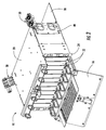
- connector housing 10 Illustrated in Figs. 1-3 is an exemplary connector housing 10 according to the present invention.
- Connector housing 10 is typically mounted to a distribution frame (not shown) and used for organizing, routing, protecting, and storing optical connections and cables of a communication network.
- connector housing 10 includes a housing assembly 12, a pair of cable entry plate assemblies 40, at least one strain relief bracket assembly 50, and a fiber management shelf 60.
- connector housing 10 has the strain relief bracket assemblies 50 removed as would be typical for clearance purposes when installing the same into a distribution frame. As best shown in Fig.
- housing assembly 12 includes a bottom panel 13, a first side panel 14, a second side panel 15, a front panel 16, a rear panel 18, a top panel 20, and a pair of rack mounts 24.
- the panels and sides of housing assembly 12 generally define an interior space of connector housing 10.
- Front and rear panels 16, 18 are rotatable from latched closed positions to open positions, thereby allowing the craftsman access to the interior space respectively from both the front and the rear.
- Cable entry plate assemblies 40 include a plate 42 and at least one grommet 44.
- Strain relief bracket assembly 50 includes a strain relief bracket 52 and at least one cable clamp 54.
- other configurations of the connector housing of the present invention are possible and intended.
- Connector housing 10 has several advantageous features making it adaptable for different applications by changing configurations.
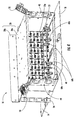
- top panel 20 includes a stationary portion 20a and a jumper management panel 20b that is rotatable relative to stationary portion 20a.
- Jumper management panel 20b includes a pair of panels 20c each having a plurality of cable routing guides (not numbered) attached thereon.
- jumper management panel may have other panel configurations thereon.
- jumper management panel 20b is securable into either a generally vertical position or a generally horizontal position for organizing and routing cables to into the front of connector housing 10. As depicted in Fig.
- jumper management panel 20b is in the generally vertical position and is secured in place using a bracket 20d having an L-shape with a stud thereon using a pair wing-nuts (not numbered). Of course, other configurations are possible for holding the jumper management panel in the vertical position. In the generally vertical position, jumper management panel 20b extends above stationary portion 20a of top panel 20. Moreover, jumper management panel 20b can be designed so that it is removable from connector housing 12.
- FIG. 9 shows connector housing 10 with jumper mangagement panel 20b in a generally vertical position having a cable assembly 57a being routed through two cable routing guides of jumper management panel 20b to a first adapter 23a (not visible) attached to an adapter panel 23.
- Fig. 9 also shows a cable assembly 57b being routed through two cable routing guides (not numbered) disposed on bottom panel 13 to a second adapter 23a on the same adapter panel 23.
- Connector housing 10 may also advantageously include at least one cable entry plate assembly 40, thereby allowing adaptability for different cable entry configurations at the sides of connector housing 10.
- cable entry plate assembly 40 is removable so that a large number of smaller diameter cables can enter connector housing 10 from the side, rather than a small number of larger diameter cables.
- Fig 4 depicts connector assembly 10 having both cable entry plate assemblies 40 respectfully attached to first and second side panels 14,15.
- a cable entry plate is not an assembly having grommets, but instead is merely a removable cable entry plate.
- Strain relief bracket assemblies 50 include strain relief bracket 52 and at least one cable clamp 54.
- Cable clamp 54 can have any suitable design.
- a suitable cable clamp is disclosed in U.S. Pat. No. 5,742,982. From there, the cable proceeds to cable entry plate assembly 40 to enter an interior space of connector housing 10.
- Cable entry plate housing 40 includes a plate 42 having at least one grommet 44 that is soft and flexible, thereby inhibiting the cable from chaffing against a rigid edge.
- cable entry plate assembly 40 includes two grommets 44 so that multiple cables may enter a single side of connector housing 10.
- cables may enter the connector housing from the top, the bottom, or both. If a cable was entering from below, a strain relief bracket assembly is attachable near the bottom of the connector housing side panel.
- connector housing 10 is suitable for either a small number of larger diameter cables entering through grommets 44 or a relatively limited number smaller diameter cables entering through grommets 44.
- connector housing 10 may have more capacity for organizing and housing optical connections than can be provided in cables that can enter through grommets 44.
- Fig. 5 shows a rear perspective view of connector housing having both cable entry plate assemblies 40 removed, thereby leaving larger cable entry areas compared with the area provided by grommets 44.
- cable entry plate assemblies are removable a larger number of cables can enter connector housing 10, thereby utilizing the entire capacity of same. This feature is especially useful when connector housing is used for connecting a relatively large number of single fiber and/or low-count fiber cables. Additionally, when cable entry plate assemblies 40 are removed, strain relief bracket assemblies can still be attached to connector housing 10.
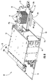
- Embodiments of the connector housing according to the present invention may also include one or more fiber management shelves 60 as best shown in Figs. 4 and 5.
- Fiber management shelf 60 is removably attached to housing assembly 12 and allows for routing and organization of cables/optical waveguides that enter the connector housing from the sides at the rear.
- fiber management shelf 60 includes at least one fastener 60a for securing it to housing assembly 12.
- fiber management shelf 60 includes two push pin fasteners that engage brackets 13a on bottom panel 13 as best shown in Fig. 7.
- any other suitable fasteners or attachment means can be used for securing fiber management shelf 60.
- fiber management shelf 60 can be attached to other panels of housing assembly 12. For instance, Fig.
- Fiber management shelf 60 also includes a plurality of cable routing guides 60b and a plurality of apertures (not numbered) adjacent to a slot for attaching cable ties, thereby allowing for organization and grouping of cables/optical waveguides.
- Figs. 4 and 5 also depicts the connector housing of Fig. 1 having a plurality of adapter panels 23 each having pluralities of adapters 23a therein substituted for a plurality of blank panels 22 as shown in Figs. 2 and 3.
- the plurality of adapters 23a are gang mounted on adapter panel 23, thereby increasing connection density.
- Adapters 23a are used for connecting and making optical connections between the cables/optical waveguides at the front of the connector housing and the cables/optical waveguides at the rear of the connector housing.
- Adapter panels 23 and blank panels 22 are attached to housing assembly 12 using fasteners (not numbered), preferably, fasteners that do not require tools and are quick and easy for the craftsman. In this case, adapter panels 23 and blank panels 22 use push pin fasteners near the top and bottom, thereby allowing the craftsman to quickly and easily remove the same.
- the present invention contemplates still other network configurations such as splicing at the connector housing.
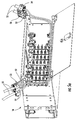
- Figs. 6-8 depict connector housing 10' which replaces fiber management shelf 60 of connector housing 10 with a splice shelf assembly 70.
- Figs. 7 and 8 show connector housing 10 having rear panel 18 removed for the purpose of clarity. In this configuration, it is possible to route optical fibers into the connector housing for fusion splicing and storage of the splices within splice trays.
- Splice shelf assembly 70 includes a splice shelf 72 that has a first portion 72a and a second portion 72b with hingable portion therebetween so that second portion 72b may rotate with respect to first portion 72a.
- first portion 72a of splice shelf 70 is secured to connector housing 12. More specifically, first portion 72a is secured to second side panel 15 using wing nuts that thread onto studs (not numbered) of second side panel 15.
- first portion 72a of splice shelf 72 could be attached on other sides or panels of connector housing 12 such as first side panel 14 and/or use other securement means such as welding, hex nuts, or clips.
- Splice shelf assembly 70 When installed, second portion 72b of splice shelf 70 rotates about a generally vertical axis and when in the fully open extends beyond rear panel 18 as shown in Fig. 6.
- Splice shelf assembly 70 is advantageous because it rotates the slack storage of cables/optical waveguides attached and/or spliced thereon when splice shelf assembly 70 rotates.
- the slack storage of cables/optical waveguides is easily moved and inhibits stresses and/or strain on the same, thereby allowing the craftsman quick and easy access to rear of adapter panels 23. Stress and/or strain are generally minimized since the cable/optical waveguides merely rotate about a point.
- splice shelf assembly 70 also includes a splice tray organizer 74, a latch mechanism 76, a plurality of cable routing guides 77, and a support trough 78 that may include a decal.
- Tray organizer 74 is attached to second portion 72b of splice shelf 72 and has a plurality of shelves (not numbered) for holding a plurality splice trays 85 as depicted in Figs. 7 and 8.
- Splice trays 85 are used for storing the splices between optical waveguides; however, splice trays 85 do not form a portion splice shelf assembly 70.
- Splice shelf assembly may also include a latch mechanism 76 for securing second portion 72b in a closed position within the interior space of connector housing 10'.
- Latch mechanism 76 engages a stop bracket 80 that in this case is mounted to bottom panel 13 of housing assembly 12 using a wing nut as best shown in Fig. 8.
- stop bracket 80 advantageously allows for easy configuration changes, but stop bracket 80 could be mounted in other ways and/or locations.
- other latching mechanisms for securing splice shelf assembly 70 from unintended rotation are also possible such as a detent or a magnet.
- Splice shelf assembly 70 also includes a plurality of cable routing guides for aiding in the organization and routing of cables/optical waveguides. Additionally, as shown in Fig. 8 an end 72c of splice shelf 72 has a generally curved portion. The generally curved portion of end 72c is for maintaining a predetermined bend radius as cable/optical waveguides are routed from a backside of splice shelf 72 to the front side having tray organizer 74. Furthermore, splice shelf assembly 72 further includes a plurality of cable routing guides 77 and fiber support trough 78 for cable/optical waveguide routing, securement and management, thereby aiding the rotation of the cable/optical with splice shelf assembly 70.
- the splice shelf assembly may also include a splice identification panel or label for recording network connections.
- a splice identification panel or label for recording network connections may be used.
- other configurations of the splice shelf assembly are possible and within the scope of the present invention, for instance, other configuration or types of tray organizers and/or splice shelves may be used.
- Figs. 10 and 11 depict a strain relief bracket assembly 100 of the present invention having a different configuration.
- Fig. 10 shows two strain relief bracket assemblies 100 attached to respective opposite sides of connector housing 10.
- strain relief bracket assembly 100 includes a strain relief bracket 101, at least one furcation plug 102 that forms a portion of a cable assembly (not shown), at least mounting rail 104, and mounting hardware 106.
- furcation plug 102 is a portion of a cable assembly and may form the transition point where a larger cable is furcated into a plurality of units having fewer optical waveguides than the entirety of the larger cable.
- Furcation plug 102 has a channel portion 102a that generally runs along a portion of a longitudinal length of furcation plug 102.
- Channel portion 102a may cooperate with a mounting rail 104 that acts as a mounting adapter and is sized for allowing channel portion 102a to slide snuggly thereon.
- Mounting rail 104 also includes a tab portion 104a having a pair of apertures (not numbered) for securing the same to strain relief bracket 101 using mounting hardware.
- suitable mounting hardware 106 is a pair of studs and nuts; however, other suitable mounting hardware such as bolts and nuts are possible.
- strain relief bracket 101 can be configured for mounting more than one furcation plug 102 as depicted.
- Fig. 11a depicts another embodiment where mounting rail that acts as an adapter is integrated into strain relief bracket 101'.
- strain relief bracket 101' includes a mounting rail 101a forming thereon for securing furcation plug 102 by engaging channel 102a.
- other configurations for mounting furcation plug 102 using the concepts of the present invention are possible.
- connector housings of the present invention can include other advantageous features.
- front panel 16 may include an aperture having an insert 16b that is removable so that an optional locking mechanism (not shown) may be attached, thereby restricting access of connector housing 10 to authorized personnel.
- rear panel 18 may also have an aperture for receiving a locking mechanism.
- the projection of connector housing 10 from the distribution frame can be varied by moving rack mounts 24 into different mounting positions along sides 14,15 using the plurality of threaded bores (not numbered) thereon.
- Connector housings of the present invention may also include a panel 90 as shown in Fig. 3 having a decal that extends and stores into the connector housing so that the craftsman can record the interconnection of links in the communication network.
- the connector housing can have other configurations such as a larger height, or different width thereby occupying more rack space.
- the connector housing can have one or more jumper management panels that can be located in other locations such as at the rear of the connector housing.
- the jumper management panel can include more than two positions. Therefore, it is to be understood that the invention is not to be limited to the specific embodiments disclosed and that modifications and other embodiments may be made within the scope of the appended claims.
- specific terms are employed herein, they are used in a generic and descriptive sense only and not for purposes of limitation. The invention has been described with reference to an optical connector housing, but the inventive concepts of the present invention are applicable to other suitable communication networks as well.
Abstract
Description
- The present invention relates generally to a connector housing for organizing, routing, and storing optical connections such as splices and/or connectors between optical waveguides.
- In telecommunication infrastructure installations, equipment for switching, cross-connecting and inter-connecting a variety of devices are used. Many of these devices are installed in telecommunication equipment racks, thereby permitting organized, high-density installations in a limited space. For instance, connector housings are installed in telecommunication equipment racks to allow the craftsman access to multiple connections at a single point. Connector housings allow the craftsman to perform necessary maintenance and/or reconfigure the communication network as necessary. It is desirable to have a high density of connections in a given space while still allowing the craftsman easy access, organization, and handling of connections and cables leading to and within the connector housing.
-
- Fig. 1 is a front perspective view of a connector housing according to one embodiment of the present invention.
- Fig. 2 is a front perspective view of the connector housing of Fig. 1 having with the front panel, the rear panel, and the jumper management panel in open positions with strain relief brackets.
- Fig. 3 is a front partially exploded, partially perspective view of the connector housing of Fig. 2.
- Fig. 4 is a rear perspective view of the connector housing of Fig. 1 with the substitution of a plurality of adapter panels for the blank panels of Fig. 1.
- Fig. 5 is a rear perspective view of the embodiment of Fig. 4 with the cable entry plate assemblies removed.
- Fig. 5a depicts the connector housing of Fig. 4 having portions of cables being attached to respective strain relief bracket assemblies and entering the connector housing.
- Fig. 6 is a side perspective view of another embodiment of a connector housing configured for splicing applications with an optional splice shelf assembly that is rotated into an exposed position.
- Fig. 7 is a rear perspective view of the connector housing of Fig. 6 with the addition of a splice tray that is removed from the splice shelf assembly.
- Fig. 8 is another rear perspective view of the connector housing of Fig. 6.
- Fig. 9 depicts a plurality of cable assemblies being routed to the front of the connector housing of Fig. 1 with the addition of another configuration of strain relief bracket assemblies.
- Fig. 10 depicts the connector housing of Fig. 1 having portions of cable assemblies being attached to another configuration of a strain relief bracket assembly and entering the connector housing according to the present invention.
- Fig. 11 is a partially exploded view of the strain relief bracket assembly depicted in Fig. 10 with the cables removed.
- Fig. 11a is a partially exploded view of another strain relief bracket assembly according to the present invention.
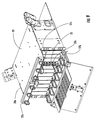
- Illustrated in Figs. 1-3 is an
exemplary connector housing 10 according to the present invention.Connector housing 10 is typically mounted to a distribution frame (not shown) and used for organizing, routing, protecting, and storing optical connections and cables of a communication network. As depicted in Figs. 2 and 3,connector housing 10 includes ahousing assembly 12, a pair of cableentry plate assemblies 40, at least one strainrelief bracket assembly 50, and afiber management shelf 60. In Fig. 1,connector housing 10 has the strainrelief bracket assemblies 50 removed as would be typical for clearance purposes when installing the same into a distribution frame. As best shown in Fig. 3,housing assembly 12 includes abottom panel 13, afirst side panel 14, asecond side panel 15, afront panel 16, arear panel 18, atop panel 20, and a pair ofrack mounts 24. The panels and sides ofhousing assembly 12 generally define an interior space ofconnector housing 10. Front andrear panels entry plate assemblies 40 include aplate 42 and at least onegrommet 44. Strainrelief bracket assembly 50 includes astrain relief bracket 52 and at least onecable clamp 54. Of course, other configurations of the connector housing of the present invention are possible and intended. -
Connector housing 10 has several advantageous features making it adaptable for different applications by changing configurations. For instance,top panel 20 includes astationary portion 20a and ajumper management panel 20b that is rotatable relative tostationary portion 20a.Jumper management panel 20b includes a pair ofpanels 20c each having a plurality of cable routing guides (not numbered) attached thereon. However, jumper management panel may have other panel configurations thereon. In this embodiment,jumper management panel 20b is securable into either a generally vertical position or a generally horizontal position for organizing and routing cables to into the front ofconnector housing 10. As depicted in Fig. 3,jumper management panel 20b is in the generally vertical position and is secured in place using abracket 20d having an L-shape with a stud thereon using a pair wing-nuts (not numbered). Of course, other configurations are possible for holding the jumper management panel in the vertical position. In the generally vertical position,jumper management panel 20b extends abovestationary portion 20a oftop panel 20. Moreover,jumper management panel 20b can be designed so that it is removable fromconnector housing 12. - When jumper management panel is secured in the generally horizontal position it is generally flush with
stationary portion 20a andbracket 20d is not necessary; instead,bracket 20d is stored by securing the same with the wing-nut that fastensjumper management panel 20b. Fig. 9 showsconnector housing 10 withjumper mangagement panel 20b in a generally vertical position having acable assembly 57a being routed through two cable routing guides ofjumper management panel 20b to afirst adapter 23a (not visible) attached to anadapter panel 23. Fig. 9 also shows acable assembly 57b being routed through two cable routing guides (not numbered) disposed onbottom panel 13 to asecond adapter 23a on thesame adapter panel 23. -
Connector housing 10 may also advantageously include at least one cableentry plate assembly 40, thereby allowing adaptability for different cable entry configurations at the sides ofconnector housing 10. Specifically, cableentry plate assembly 40 is removable so that a large number of smaller diameter cables can enterconnector housing 10 from the side, rather than a small number of larger diameter cables. Illustratively, Fig 4 depictsconnector assembly 10 having both cableentry plate assemblies 40 respectfully attached to first andsecond side panels cables 55 are respectively secured and strain relieved at strain relief bracket assemblies 50. Strainrelief bracket assemblies 50 includestrain relief bracket 52 and at least onecable clamp 54.Cable clamp 54 can have any suitable design. A suitable cable clamp is disclosed in U.S. Pat. No. 5,742,982. From there, the cable proceeds to cableentry plate assembly 40 to enter an interior space ofconnector housing 10. Cableentry plate housing 40 includes aplate 42 having at least onegrommet 44 that is soft and flexible, thereby inhibiting the cable from chaffing against a rigid edge. In this case, cableentry plate assembly 40 includes twogrommets 44 so that multiple cables may enter a single side ofconnector housing 10. Moreover, cables may enter the connector housing from the top, the bottom, or both. If a cable was entering from below, a strain relief bracket assembly is attachable near the bottom of the connector housing side panel. With cableentry plate assemblies 40 attached,connector housing 10 is suitable for either a small number of larger diameter cables entering throughgrommets 44 or a relatively limited number smaller diameter cables entering throughgrommets 44. However,connector housing 10 may have more capacity for organizing and housing optical connections than can be provided in cables that can enter throughgrommets 44. - On the other hand, Fig. 5 shows a rear perspective view of connector housing having both cable
entry plate assemblies 40 removed, thereby leaving larger cable entry areas compared with the area provided bygrommets 44. In other words, because cable entry plate assemblies are removable a larger number of cables can enterconnector housing 10, thereby utilizing the entire capacity of same. This feature is especially useful when connector housing is used for connecting a relatively large number of single fiber and/or low-count fiber cables. Additionally, when cableentry plate assemblies 40 are removed, strain relief bracket assemblies can still be attached toconnector housing 10. - Embodiments of the connector housing according to the present invention may also include one or more
fiber management shelves 60 as best shown in Figs. 4 and 5.Fiber management shelf 60 is removably attached tohousing assembly 12 and allows for routing and organization of cables/optical waveguides that enter the connector housing from the sides at the rear. Specifically,fiber management shelf 60 includes at least one fastener 60a for securing it tohousing assembly 12. In this embodiment,fiber management shelf 60 includes two push pin fasteners that engagebrackets 13a onbottom panel 13 as best shown in Fig. 7. However any other suitable fasteners or attachment means can be used for securingfiber management shelf 60. Moreover,fiber management shelf 60 can be attached to other panels ofhousing assembly 12. For instance, Fig. 5 depicts twofiber management shelves 60 respectively attached to bottom andtop panels Fiber management shelf 60 also includes a plurality of cable routing guides 60b and a plurality of apertures (not numbered) adjacent to a slot for attaching cable ties, thereby allowing for organization and grouping of cables/optical waveguides. - Figs. 4 and 5 also depicts the connector housing of Fig. 1 having a plurality of
adapter panels 23 each having pluralities ofadapters 23a therein substituted for a plurality ofblank panels 22 as shown in Figs. 2 and 3. The plurality ofadapters 23a are gang mounted onadapter panel 23, thereby increasing connection density.Adapters 23a are used for connecting and making optical connections between the cables/optical waveguides at the front of the connector housing and the cables/optical waveguides at the rear of the connector housing.Adapter panels 23 andblank panels 22 are attached tohousing assembly 12 using fasteners (not numbered), preferably, fasteners that do not require tools and are quick and easy for the craftsman. In this case,adapter panels 23 andblank panels 22 use push pin fasteners near the top and bottom, thereby allowing the craftsman to quickly and easily remove the same. - The present invention contemplates still other network configurations such as splicing at the connector housing. Figs. 6-8 depict connector housing 10' which replaces
fiber management shelf 60 ofconnector housing 10 with asplice shelf assembly 70. Figs. 7 and 8show connector housing 10 havingrear panel 18 removed for the purpose of clarity. In this configuration, it is possible to route optical fibers into the connector housing for fusion splicing and storage of the splices within splice trays. -
Splice shelf assembly 70 includes asplice shelf 72 that has afirst portion 72a and asecond portion 72b with hingable portion therebetween so thatsecond portion 72b may rotate with respect tofirst portion 72a. When assembled,first portion 72a ofsplice shelf 70 is secured toconnector housing 12. More specifically,first portion 72a is secured tosecond side panel 15 using wing nuts that thread onto studs (not numbered) ofsecond side panel 15. Of course,first portion 72a ofsplice shelf 72 could be attached on other sides or panels ofconnector housing 12 such asfirst side panel 14 and/or use other securement means such as welding, hex nuts, or clips. When installed,second portion 72b ofsplice shelf 70 rotates about a generally vertical axis and when in the fully open extends beyondrear panel 18 as shown in Fig. 6.Splice shelf assembly 70 is advantageous because it rotates the slack storage of cables/optical waveguides attached and/or spliced thereon whensplice shelf assembly 70 rotates. In other words, the slack storage of cables/optical waveguides is easily moved and inhibits stresses and/or strain on the same, thereby allowing the craftsman quick and easy access to rear ofadapter panels 23. Stress and/or strain are generally minimized since the cable/optical waveguides merely rotate about a point. - As shown,
splice shelf assembly 70 also includes asplice tray organizer 74, alatch mechanism 76, a plurality of cable routing guides 77, and asupport trough 78 that may include a decal.Tray organizer 74 is attached tosecond portion 72b ofsplice shelf 72 and has a plurality of shelves (not numbered) for holding aplurality splice trays 85 as depicted in Figs. 7 and 8.Splice trays 85 are used for storing the splices between optical waveguides; however, splicetrays 85 do not form a portionsplice shelf assembly 70. Splice shelf assembly may also include alatch mechanism 76 for securingsecond portion 72b in a closed position within the interior space of connector housing 10'.Latch mechanism 76 engages astop bracket 80 that in this case is mounted tobottom panel 13 ofhousing assembly 12 using a wing nut as best shown in Fig. 8. Using this mounting configuration forstop bracket 80 advantageously allows for easy configuration changes, but stopbracket 80 could be mounted in other ways and/or locations. Additionally, other latching mechanisms for securingsplice shelf assembly 70 from unintended rotation are also possible such as a detent or a magnet. -
Splice shelf assembly 70 also includes a plurality of cable routing guides for aiding in the organization and routing of cables/optical waveguides. Additionally, as shown in Fig. 8 anend 72c ofsplice shelf 72 has a generally curved portion. The generally curved portion ofend 72c is for maintaining a predetermined bend radius as cable/optical waveguides are routed from a backside ofsplice shelf 72 to the front side havingtray organizer 74. Furthermore,splice shelf assembly 72 further includes a plurality of cable routing guides 77 andfiber support trough 78 for cable/optical waveguide routing, securement and management, thereby aiding the rotation of the cable/optical withsplice shelf assembly 70. The splice shelf assembly may also include a splice identification panel or label for recording network connections. Of course other configurations of the splice shelf assembly are possible and within the scope of the present invention, for instance, other configuration or types of tray organizers and/or splice shelves may be used. - Figs. 10 and 11 depict a strain
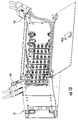
relief bracket assembly 100 of the present invention having a different configuration. Fig. 10 shows two strainrelief bracket assemblies 100 attached to respective opposite sides ofconnector housing 10. As best shown in Fig. 11, strainrelief bracket assembly 100 includes astrain relief bracket 101, at least onefurcation plug 102 that forms a portion of a cable assembly (not shown), at least mountingrail 104, and mountinghardware 106. Generally speaking,furcation plug 102 is a portion of a cable assembly and may form the transition point where a larger cable is furcated into a plurality of units having fewer optical waveguides than the entirety of the larger cable.Furcation plug 102 has achannel portion 102a that generally runs along a portion of a longitudinal length offurcation plug 102.Channel portion 102a may cooperate with a mountingrail 104 that acts as a mounting adapter and is sized for allowingchannel portion 102a to slide snuggly thereon. Mountingrail 104 also includes atab portion 104a having a pair of apertures (not numbered) for securing the same to strainrelief bracket 101 using mounting hardware. Thus,furcation plug 102 of the cable assembly is quickly and easily mounted and/or removed from mountingrail 104 by the craftsman without tools. Mountingrail 104 is attached to strainrelief bracket 101 using suitable mountinghardware 106. For instance, mountinghardware 106 is a pair of studs and nuts; however, other suitable mounting hardware such as bolts and nuts are possible. In this case, the studs are inserted through apertures instrain relief bracket 101 having a predetermined spacing that matches the spacing of the apertures intab 104a as shown. Additionally,strain relief bracket 101 can be configured for mounting more than onefurcation plug 102 as depicted. Fig. 11a depicts another embodiment where mounting rail that acts as an adapter is integrated into strain relief bracket 101'. In this case, strain relief bracket 101' includes a mountingrail 101a forming thereon for securingfurcation plug 102 by engagingchannel 102a. Additionally, other configurations for mountingfurcation plug 102 using the concepts of the present invention are possible. - Futhermore, connector housings of the present invention can include other advantageous features. By way of example,
front panel 16 may include an aperture having an insert 16b that is removable so that an optional locking mechanism (not shown) may be attached, thereby restricting access ofconnector housing 10 to authorized personnel. Likewise,rear panel 18 may also have an aperture for receiving a locking mechanism. Additionally, as depicted in Fig. 3, the projection ofconnector housing 10 from the distribution frame can be varied by moving rack mounts 24 into different mounting positions alongsides panel 90 as shown in Fig. 3 having a decal that extends and stores into the connector housing so that the craftsman can record the interconnection of links in the communication network. - Many modifications and other embodiments of the present invention, within the scope of the appended claims, will become apparent to a skilled artisan. For example, the connector housing can have other configurations such as a larger height, or different width thereby occupying more rack space. Additionally, the connector housing can have one or more jumper management panels that can be located in other locations such as at the rear of the connector housing. Moreover, the jumper management panel can include more than two positions. Therefore, it is to be understood that the invention is not to be limited to the specific embodiments disclosed and that modifications and other embodiments may be made within the scope of the appended claims. Although specific terms are employed herein, they are used in a generic and descriptive sense only and not for purposes of limitation. The invention has been described with reference to an optical connector housing, but the inventive concepts of the present invention are applicable to other suitable communication networks as well.
Claims (15)
- A connector housing for a communications network comprising:a housing assembly having a front panel that is rotatable, a rear panel that is rotatable, a first side panel, a second side panel, a bottom panel, and a top panel; anda jumper management panel that is rotatable into at least two different positions relative to the top panel of the housing assembly.
- The connector housing of claim 1, further including a bracket for securing the jumper management panel in an upright position.
- The connector housing of claim 1, the jumper management panel having a plurality of cable routing guides.
- The connector housing of claim 1, further including a splice shelf assembly, the splice shelf assembly being attached to the housing assembly and rotatable relative to the housing assembly.
- The connector housing of claim 4, the splice shelf assembly being rotatable about a generally vertical axis.
- The connector housing of claim 4, the splice shelf assembly having a latch mechanism for securing the splice shelf assembly in a stored position.
- The connector housing of claim 4, the splice shelf assembly being removably attached to a side panel of the housing assembly.
- The connector housing of claim 1, further comprising at least one fiber management shelf that is detachable, the fiber management shelf having a plurality of cable routing guides thereon.
- A connector housing for a communications network comprising:a housing assembly having a front panel that is rotatable, a rear panel that is rotatable, a first side panel, a second side panel, a bottom panel, and a top panel; anda splice shelf assembly, the splice shelf assembly being attached to the housing assembly and rotatable relative to the housing assembly about a generally vertical axis, the splice shelf assembly being able to hold optical waveguides, thereby allowing the optical waveguide to rotate with the splice shelf assembly.
- The connector housing of claim 9, the splice shelf assembly having a latch mechanism for securing the splice shelf assembly in a stored position.
- The connector housing of claim 9, the splice shelf assembly extending beyond the rear panel when rotated into the fully rotated position.
- The connector housing of claim 9, the splice shelf assembly being removably attached to a side panel of the housing assembly.
- The connector housing of claim 9, further including a jumper management panel that is rotatable into at least two different positions relative to the top panel of the housing assembly.
- The connector housing of claim 13, further including a bracket for securing the jumper management panel in an upright position.
- The connector housing of claim 13, the jumper management panel having a plurality of cable routing guides.
Applications Claiming Priority (1)
| Application Number | Priority Date | Filing Date | Title |
|---|---|---|---|
| US10/903,746 US7200316B2 (en) | 2003-11-26 | 2004-07-30 | Connector housing for a communication network |
Publications (2)
| Publication Number | Publication Date |
|---|---|
| EP1621907A1 true EP1621907A1 (en) | 2006-02-01 |
| EP1621907B1 EP1621907B1 (en) | 2017-09-13 |
Family
ID=35241011
Family Applications (1)
| Application Number | Title | Priority Date | Filing Date |
|---|---|---|---|
| EP05016256.9A Not-in-force EP1621907B1 (en) | 2004-07-30 | 2005-07-27 | Distribution frame for an optical communication network |
Country Status (3)
| Country | Link |
|---|---|
| US (1) | US7200316B2 (en) |
| EP (1) | EP1621907B1 (en) |
| CA (1) | CA2513482C (en) |
Cited By (32)
| Publication number | Priority date | Publication date | Assignee | Title |
|---|---|---|---|---|
| WO2010062626A1 (en) * | 2008-10-27 | 2010-06-03 | Corning Cable Systems Llc | Variably configurable and modular local convergence point |
| WO2011140540A1 (en) * | 2010-05-07 | 2011-11-10 | Corning Cable Systems Llc | Door fiber management for fiber optic housings, and related components and methods |
| WO2011140539A1 (en) * | 2010-05-07 | 2011-11-10 | Corning Cable Systems Llc | Removable fiber management devices for fiber optic housings, and related components and methods |
| EP2434323A1 (en) * | 2010-09-27 | 2012-03-28 | Draka Comteq B.V. | Modular patch box |
| WO2012069084A1 (en) * | 2010-11-25 | 2012-05-31 | Prysmian S.P.A. | Optical box |
| US8699838B2 (en) | 2009-05-14 | 2014-04-15 | Ccs Technology, Inc. | Fiber optic furcation module |
| US8712206B2 (en) | 2009-06-19 | 2014-04-29 | Corning Cable Systems Llc | High-density fiber optic modules and module housings and related equipment |
| US8879881B2 (en) | 2010-04-30 | 2014-11-04 | Corning Cable Systems Llc | Rotatable routing guide and assembly |
| US8879882B2 (en) | 2008-10-27 | 2014-11-04 | Corning Cable Systems Llc | Variably configurable and modular local convergence point |
| US8913866B2 (en) | 2010-03-26 | 2014-12-16 | Corning Cable Systems Llc | Movable adapter panel |
| US8953924B2 (en) | 2011-09-02 | 2015-02-10 | Corning Cable Systems Llc | Removable strain relief brackets for securing fiber optic cables and/or optical fibers to fiber optic equipment, and related assemblies and methods |
| US8985862B2 (en) | 2013-02-28 | 2015-03-24 | Corning Cable Systems Llc | High-density multi-fiber adapter housings |
| US8989547B2 (en) | 2011-06-30 | 2015-03-24 | Corning Cable Systems Llc | Fiber optic equipment assemblies employing non-U-width-sized housings and related methods |
| US8992099B2 (en) | 2010-02-04 | 2015-03-31 | Corning Cable Systems Llc | Optical interface cards, assemblies, and related methods, suited for installation and use in antenna system equipment |
| US8995812B2 (en) | 2012-10-26 | 2015-03-31 | Ccs Technology, Inc. | Fiber optic management unit and fiber optic distribution device |
| US9008485B2 (en) | 2011-05-09 | 2015-04-14 | Corning Cable Systems Llc | Attachment mechanisms employed to attach a rear housing section to a fiber optic housing, and related assemblies and methods |
| US9020320B2 (en) | 2008-08-29 | 2015-04-28 | Corning Cable Systems Llc | High density and bandwidth fiber optic apparatuses and related equipment and methods |
| US9022814B2 (en) | 2010-04-16 | 2015-05-05 | Ccs Technology, Inc. | Sealing and strain relief device for data cables |
| US9038832B2 (en) | 2011-11-30 | 2015-05-26 | Corning Cable Systems Llc | Adapter panel support assembly |
| US9042702B2 (en) | 2012-09-18 | 2015-05-26 | Corning Cable Systems Llc | Platforms and systems for fiber optic cable attachment |
| US9059578B2 (en) | 2009-02-24 | 2015-06-16 | Ccs Technology, Inc. | Holding device for a cable or an assembly for use with a cable |
| US9075216B2 (en) | 2009-05-21 | 2015-07-07 | Corning Cable Systems Llc | Fiber optic housings configured to accommodate fiber optic modules/cassettes and fiber optic panels, and related components and methods |
| US9075217B2 (en) | 2010-04-30 | 2015-07-07 | Corning Cable Systems Llc | Apparatuses and related components and methods for expanding capacity of fiber optic housings |
| US9116324B2 (en) | 2010-10-29 | 2015-08-25 | Corning Cable Systems Llc | Stacked fiber optic modules and fiber optic equipment configured to support stacked fiber optic modules |
| US9213161B2 (en) | 2010-11-05 | 2015-12-15 | Corning Cable Systems Llc | Fiber body holder and strain relief device |
| US9250409B2 (en) | 2012-07-02 | 2016-02-02 | Corning Cable Systems Llc | Fiber-optic-module trays and drawers for fiber-optic equipment |
| US9279951B2 (en) | 2010-10-27 | 2016-03-08 | Corning Cable Systems Llc | Fiber optic module for limited space applications having a partially sealed module sub-assembly |
| US9519118B2 (en) | 2010-04-30 | 2016-12-13 | Corning Optical Communications LLC | Removable fiber management sections for fiber optic housings, and related components and methods |
| CN102884466B (en) * | 2010-05-07 | 2016-12-14 | 康宁光缆系统有限责任公司 | For the door fiber management of optical fiber case, and relevant assembly and method |
| US9645317B2 (en) | 2011-02-02 | 2017-05-09 | Corning Optical Communications LLC | Optical backplane extension modules, and related assemblies suitable for establishing optical connections to information processing modules disposed in equipment racks |
| US10094996B2 (en) | 2008-08-29 | 2018-10-09 | Corning Optical Communications, Llc | Independently translatable modules and fiber optic equipment trays in fiber optic equipment |
| US11294136B2 (en) | 2008-08-29 | 2022-04-05 | Corning Optical Communications LLC | High density and bandwidth fiber optic apparatuses and related equipment and methods |
Families Citing this family (88)
| Publication number | Priority date | Publication date | Assignee | Title |
|---|---|---|---|---|
| TWM259387U (en) * | 2004-06-29 | 2005-03-11 | Lite On Technology Corp | Space allocation structure to sort the wiring of computer and peripheral equipment thereof |
| US7460758B2 (en) | 2005-06-03 | 2008-12-02 | Telect Inc. | Fiber management system |
| US7366391B2 (en) * | 2005-06-03 | 2008-04-29 | Telect Inc. | Hybrid wire-fiber management |
| US7683270B2 (en) * | 2005-06-03 | 2010-03-23 | Telect Inc. | Telecommunications cabinet |
| DE202005019319U1 (en) * | 2005-12-08 | 2006-02-16 | CCS Technology, Inc., Wilmington | Built-in element for a cable distributor housing |
| US7357667B2 (en) * | 2006-06-22 | 2008-04-15 | Adc Telecommunications, Inc. | Telecommunications patch |
| US7711234B2 (en) * | 2006-10-02 | 2010-05-04 | Adc Telecommunications, Inc. | Reskinnable fiber distribution hub |
| US7570861B2 (en) | 2007-01-19 | 2009-08-04 | Adc Telecommunications, Inc. | Adapter panel with lateral sliding adapter arrays |
| US7570860B2 (en) | 2007-01-19 | 2009-08-04 | Adc Telecommunications, Inc. | Adapter panel with lateral sliding adapter arrays |
| US7822310B2 (en) * | 2007-02-28 | 2010-10-26 | Corning Cable Systems Llc | Fiber optic splice trays |
| US7974094B2 (en) * | 2007-03-27 | 2011-07-05 | Commscope, Inc. Of North Carolina | Outside plant telecommunications cabinet direct air cooling system |
| US7620287B2 (en) * | 2007-05-31 | 2009-11-17 | Corning Cable Systems Llc | Telecommunications housing with optical fiber management |
| US8798427B2 (en) | 2007-09-05 | 2014-08-05 | Corning Cable Systems Llc | Fiber optic terminal assembly |
| US8179684B2 (en) * | 2007-10-29 | 2012-05-15 | Adc Telecommunications, Inc. | Sliding adapter panel with living hinge and forward/rearward locking |
| US8263867B2 (en) | 2008-01-07 | 2012-09-11 | Chatsworth Products, Inc. | Cable management accessories |
| WO2009089008A2 (en) * | 2008-01-07 | 2009-07-16 | Corning Cable Systems Llc | Apparatus and method for organizing cables in a cabinet |
| SE535066C2 (en) | 2008-01-07 | 2012-04-03 | Chatsworth Prod Inc | Vertical cable management device |
| US7889961B2 (en) * | 2008-03-27 | 2011-02-15 | Corning Cable Systems Llc | Compact, high-density adapter module, housing assembly and frame assembly for optical fiber telecommunications |
| WO2009131895A2 (en) | 2008-04-21 | 2009-10-29 | Adc Telecommunications, Inc. | Fiber optic splice tray |
| US8249410B2 (en) * | 2008-04-25 | 2012-08-21 | Corning Cable Systems Llc | Connector housing for a communication network |
| US7787740B2 (en) * | 2008-06-12 | 2010-08-31 | Corning Cable Systems Llc | Universal cable bracket |
| US8135257B2 (en) * | 2008-08-29 | 2012-03-13 | Corning Cable Systems Llc | Structures for managing and mounting cable assemblies |
| US8290333B2 (en) * | 2008-08-29 | 2012-10-16 | Corning Cable Systems Llc | Fiber optic cable assemblies with furcation bodies having features for manufacturing and methods of making the same |
| US8184938B2 (en) | 2008-08-29 | 2012-05-22 | Corning Cable Systems Llc | Rear-installable fiber optic modules and equipment |
| US8301004B2 (en) * | 2008-08-29 | 2012-10-30 | Corning Cable Systems Llc | Fiber optic cable assemblies employing a furcation body having anti-rotation feature |
| US8285104B2 (en) * | 2008-08-29 | 2012-10-09 | Corning Cable Systems Llc | Clip for securing a fiber optic cable assembly and associated assemblies |
| US7856166B2 (en) * | 2008-09-02 | 2010-12-21 | Corning Cable Systems Llc | High-density patch-panel assemblies for optical fiber telecommunications |
| US8086084B2 (en) * | 2008-09-09 | 2011-12-27 | Adc Telecommunications, Inc. | Fiber optic splice tray |
| AU2008362634A1 (en) | 2008-10-09 | 2010-04-15 | Corning Cable Systems (Shanghai) Co., Ltd | Fiber optic terminal having adapter panel supporting both input and output fibers from an optical splitter |
| EP2237091A1 (en) | 2009-03-31 | 2010-10-06 | Corning Cable Systems LLC | Removably mountable fiber optic terminal |
| US7703990B1 (en) | 2009-04-23 | 2010-04-27 | Corning Cable Systems Llc | Furcation bodies and fiber optic assemblies using the same |
| US8538226B2 (en) * | 2009-05-21 | 2013-09-17 | Corning Cable Systems Llc | Fiber optic equipment guides and rails configured with stopping position(s), and related equipment and methods |
| US7945136B2 (en) * | 2009-06-19 | 2011-05-17 | Corning Cable Systems Llc | Mounting of fiber optic cable assemblies within fiber optic shelf assemblies |
| JP2012530943A (en) | 2009-06-19 | 2012-12-06 | コーニング ケーブル システムズ リミテッド ライアビリティ カンパニー | High fiber optic cable packaging density equipment |
| US8714368B2 (en) * | 2009-09-09 | 2014-05-06 | Adc Telecommunications, Inc. | Pass-through trough |
| US8467651B2 (en) * | 2009-09-30 | 2013-06-18 | Ccs Technology Inc. | Fiber optic terminals configured to dispose a fiber optic connection panel(s) within an optical fiber perimeter and related methods |
| US8385710B2 (en) * | 2009-11-12 | 2013-02-26 | Panduit Corp. | Fiber tray |
| US8625950B2 (en) | 2009-12-18 | 2014-01-07 | Corning Cable Systems Llc | Rotary locking apparatus for fiber optic equipment trays and related methods |
| US9547144B2 (en) | 2010-03-16 | 2017-01-17 | Corning Optical Communications LLC | Fiber optic distribution network for multiple dwelling units |
| US8792767B2 (en) | 2010-04-16 | 2014-07-29 | Ccs Technology, Inc. | Distribution device |
| EP2381284B1 (en) | 2010-04-23 | 2014-12-31 | CCS Technology Inc. | Under floor fiber optic distribution device |
| US8705926B2 (en) | 2010-04-30 | 2014-04-22 | Corning Optical Communications LLC | Fiber optic housings having a removable top, and related components and methods |
| US9720195B2 (en) * | 2010-04-30 | 2017-08-01 | Corning Optical Communications LLC | Apparatuses and related components and methods for attachment and release of fiber optic housings to and from an equipment rack |
| US8660397B2 (en) | 2010-04-30 | 2014-02-25 | Corning Cable Systems Llc | Multi-layer module |
| US9632270B2 (en) | 2010-04-30 | 2017-04-25 | Corning Optical Communications LLC | Fiber optic housings configured for tool-less assembly, and related components and methods |
| US8538227B2 (en) | 2010-05-14 | 2013-09-17 | Corning Cable Systems Llc | Furcation management structures |
| US9134497B2 (en) * | 2010-05-14 | 2015-09-15 | Afl Telecommunications Llc | Fiber optic cable management module and panel |
| US8824851B2 (en) | 2010-08-27 | 2014-09-02 | Commscope, Inc. Of North Carolina | Communications enclosure having rear mounted bracket and method of securing a cable bundle to a communications enclosure using a rear mounted bracket |
| US8718436B2 (en) | 2010-08-30 | 2014-05-06 | Corning Cable Systems Llc | Methods, apparatuses for providing secure fiber optic connections |
| DE102010048585A1 (en) * | 2010-10-18 | 2012-04-19 | Adc Gmbh | Cable guide element and cassette with a cable guide element |
| US9547145B2 (en) | 2010-10-19 | 2017-01-17 | Corning Optical Communications LLC | Local convergence point for multiple dwelling unit fiber optic distribution network |
| US8662760B2 (en) | 2010-10-29 | 2014-03-04 | Corning Cable Systems Llc | Fiber optic connector employing optical fiber guide member |
| CN102468627A (en) * | 2010-11-16 | 2012-05-23 | 鸿富锦精密工业(深圳)有限公司 | Cable fixing device |
| US20120273627A1 (en) * | 2011-04-26 | 2012-11-01 | Panduit Corp. | Horizontal Cable Manager |
| US8958673B2 (en) | 2011-05-27 | 2015-02-17 | Corning Cable Systems Llc | Molded fiber optic cable furcation assemblies, and related fiber optic components, assemblies, and methods |
| US8831395B2 (en) | 2011-11-14 | 2014-09-09 | Adc Telecommunications, Inc. | Cable pulling arrangement |
| US9219546B2 (en) | 2011-12-12 | 2015-12-22 | Corning Optical Communications LLC | Extremely high frequency (EHF) distributed antenna systems, and related components and methods |
| EP2629128A1 (en) * | 2012-02-14 | 2013-08-21 | CCS Technology, Inc. | Fiber optic distribution device |
| US10110307B2 (en) | 2012-03-02 | 2018-10-23 | Corning Optical Communications LLC | Optical network units (ONUs) for high bandwidth connectivity, and related components and methods |
| EP2669726A1 (en) * | 2012-05-29 | 2013-12-04 | VV-Hammer GmbH | Splice module, component holder and fibre optic cable distributor cabinet |
| EP2680055A1 (en) * | 2012-06-28 | 2014-01-01 | Tyco Electronics Raychem BVBA | Cable storage tray |
| US9004778B2 (en) | 2012-06-29 | 2015-04-14 | Corning Cable Systems Llc | Indexable optical fiber connectors and optical fiber connector arrays |
| US9049500B2 (en) | 2012-08-31 | 2015-06-02 | Corning Cable Systems Llc | Fiber optic terminals, systems, and methods for network service management |
| US8909019B2 (en) | 2012-10-11 | 2014-12-09 | Ccs Technology, Inc. | System comprising a plurality of distribution devices and distribution device |
| US9971120B2 (en) * | 2012-10-31 | 2018-05-15 | Commscope Technologies Llc | Anchoring cables to rack with cable clamp arrangements |
| US9366836B2 (en) * | 2013-09-18 | 2016-06-14 | Hubbell Incorporated | Fiber cable and drop wire organizer |
| AU2014322984B2 (en) | 2013-09-23 | 2018-11-22 | CommScope Connectivity Belgium BVBA | Telecommunications chassis |
| CN104614822A (en) * | 2013-11-05 | 2015-05-13 | 深圳市华为安捷信电气有限公司 | Jumper fiber device, port panel and jumper fiber system |
| US9291786B2 (en) | 2013-12-31 | 2016-03-22 | All Systems Broadband, Inc. | Grommet for fiber optic enclosures |
| AU2015269194A1 (en) | 2014-06-05 | 2016-12-15 | Chatsworth Products, Inc. | Electrical receptacle with locking feature |
| US9690065B2 (en) | 2014-09-12 | 2017-06-27 | Panduit Corp. | High density fiber enclosure and method |
| EP3329570B1 (en) * | 2015-07-30 | 2021-09-08 | Sanmina Corporation | Cable management assembly for rack mounted equipment |
| US10215944B2 (en) | 2016-06-30 | 2019-02-26 | Panduit Corp. | Modular fiber optic tray |
| CA2972609C (en) * | 2016-07-06 | 2024-03-19 | Belden Canada Inc. | Labelling system for rackmount case for the accommodation of optical equipment |
| ES2929573T3 (en) * | 2017-02-23 | 2022-11-30 | Commscope Technologies Llc | High Fiber Count Termination Device |
| CN109874259B (en) * | 2017-12-05 | 2020-07-21 | 北京自动化控制设备研究所 | Assembly method of modular integrated control device |
| US10302227B1 (en) * | 2017-12-29 | 2019-05-28 | Gust Marketing, Llc | Cable organizing apparatus and system |
| US10547145B2 (en) | 2018-02-05 | 2020-01-28 | Chatworth Products, Inc. | Electric receptacle with locking feature |
| US10416406B1 (en) | 2018-03-01 | 2019-09-17 | Afl Telecommunications Llc | Communications module housing |
| US10451828B1 (en) * | 2018-11-09 | 2019-10-22 | Afl Telecommunications Llc | Communications module housing |
| US11706894B2 (en) * | 2019-08-05 | 2023-07-18 | Panduit Corp. | Cable manager with a hinged door |
| US11582538B2 (en) * | 2019-08-05 | 2023-02-14 | Panduit Corp. | Horizontal cable manager with a hinged door |
| TW202232163A (en) | 2020-09-18 | 2022-08-16 | 美商紐比斯通訊股份有限公司 | Data processing systems and apparatuses including optical communication modules and methods thereof |
| US11818860B1 (en) | 2020-12-15 | 2023-11-14 | Chatsworth Products, Inc. | Frame structure for electronic equipment enclosure |
| US11678456B1 (en) | 2020-12-15 | 2023-06-13 | Chatsworth Products, Inc. | Slidable mounting hardware for electronic equipment enclosure and method for installing same |
| US11622458B1 (en) | 2020-12-15 | 2023-04-04 | Chatsworth Products, Inc. | Brush port assembly and method for installing same |
| US11920392B1 (en) | 2021-02-02 | 2024-03-05 | Chatsworth Products, Inc. | Electrical bonding door hinges |
| CA3148577A1 (en) | 2021-02-12 | 2022-08-12 | Belden Canada Ulc | Strain relief assembly |
Citations (8)
| Publication number | Priority date | Publication date | Assignee | Title |
|---|---|---|---|---|
| US4708430A (en) * | 1984-10-25 | 1987-11-24 | Northern Telecom Limited | Cabinet for optical cable terminating equipment |
| US4792203A (en) * | 1985-09-17 | 1988-12-20 | Adc Telecommunications, Inc. | Optical fiber distribution apparatus |
| US5402515A (en) * | 1994-03-01 | 1995-03-28 | Minnesota Mining And Manufacturing Company | Fiber distribution frame system, cabinets, trays and fiber optic connector couplings |
| US5511144A (en) * | 1994-06-13 | 1996-04-23 | Siecor Corporation | Optical distribution frame |
| US5742982A (en) | 1996-11-25 | 1998-04-28 | Siecor Corporation | Cable strain relief apparatus |
| US6175079B1 (en) * | 1999-06-03 | 2001-01-16 | Tyco Electronics Corporation | Fiber optic cable management system |
| US20020150372A1 (en) * | 2001-02-12 | 2002-10-17 | Fiber Optic Network Solutions Corp. | Optical fiber enclosure system |
| US6504988B1 (en) * | 2000-01-24 | 2003-01-07 | Adc Telecommunications, Inc. | Cable management panel with sliding drawer |
Family Cites Families (18)
| Publication number | Priority date | Publication date | Assignee | Title |
|---|---|---|---|---|
| US4900123A (en) * | 1988-08-29 | 1990-02-13 | Gte Products Corporation | 1550 nm fiber distribution panel |
| US4949376A (en) * | 1989-06-15 | 1990-08-14 | Keptel, Inc. | Telephone network interface apparatus |
| US5100221A (en) * | 1990-01-22 | 1992-03-31 | Porta Systems Corp. | Optical fiber cable distribution frame and support |
| US5066149A (en) * | 1990-09-11 | 1991-11-19 | Adc Telecommunications, Inc. | Splice tray with slack take-up |
| US5109467A (en) * | 1991-02-27 | 1992-04-28 | Keptel, Inc. | Interconnect cabinet for optical fibers |
| US5490229A (en) * | 1993-12-08 | 1996-02-06 | At&T Ipm Corp. | Slidably mounted optical fiber distribution tray |
| US5530954A (en) * | 1995-01-13 | 1996-06-25 | Telect, Inc. | Telecommunication fiber optic patch panel shelf assembly |
| US5778130A (en) * | 1996-12-31 | 1998-07-07 | Siecor Corporation | Optical fiber connector housing |
| US5825962A (en) * | 1996-12-31 | 1998-10-20 | Siecor Corporation | Optical fiber splice housing |
| US5987207A (en) * | 1997-06-27 | 1999-11-16 | Siecor Corporation | Fiber organizer |
| US5946440A (en) * | 1997-11-17 | 1999-08-31 | Adc Telecommunications, Inc. | Optical fiber cable management device |
| US6201920B1 (en) * | 1998-12-28 | 2001-03-13 | Siecor Operations, Llc | Fiber optic cable wall mount housing |
| US6250816B1 (en) * | 1999-02-19 | 2001-06-26 | Tyco Electronics Corporation | Cable connector plate and method for interconnecting ends of fiber optic cable |
| US6385381B1 (en) * | 1999-09-21 | 2002-05-07 | Lucent Technologies Inc. | Fiber optic interconnection combination closure |
| US6438310B1 (en) * | 2000-01-24 | 2002-08-20 | Adc Telecommunications, Inc. | Cable management panel with sliding drawer |
| US6631237B2 (en) * | 2001-03-06 | 2003-10-07 | Adc Telecommunications, Inc. | Termination and splice panel |
| US6748155B2 (en) * | 2002-07-22 | 2004-06-08 | Adc Telecommunications, Inc. | Fiber management drawer and sliding cable slack limiter |
| US6832035B1 (en) * | 2003-05-30 | 2004-12-14 | Lucent Technologies Inc. | Optical fiber connection system |
-
2004
- 2004-07-30 US US10/903,746 patent/US7200316B2/en not_active Expired - Lifetime
-
2005
- 2005-07-26 CA CA2513482A patent/CA2513482C/en not_active Expired - Fee Related
- 2005-07-27 EP EP05016256.9A patent/EP1621907B1/en not_active Not-in-force
Patent Citations (8)
| Publication number | Priority date | Publication date | Assignee | Title |
|---|---|---|---|---|
| US4708430A (en) * | 1984-10-25 | 1987-11-24 | Northern Telecom Limited | Cabinet for optical cable terminating equipment |
| US4792203A (en) * | 1985-09-17 | 1988-12-20 | Adc Telecommunications, Inc. | Optical fiber distribution apparatus |
| US5402515A (en) * | 1994-03-01 | 1995-03-28 | Minnesota Mining And Manufacturing Company | Fiber distribution frame system, cabinets, trays and fiber optic connector couplings |
| US5511144A (en) * | 1994-06-13 | 1996-04-23 | Siecor Corporation | Optical distribution frame |
| US5742982A (en) | 1996-11-25 | 1998-04-28 | Siecor Corporation | Cable strain relief apparatus |
| US6175079B1 (en) * | 1999-06-03 | 2001-01-16 | Tyco Electronics Corporation | Fiber optic cable management system |
| US6504988B1 (en) * | 2000-01-24 | 2003-01-07 | Adc Telecommunications, Inc. | Cable management panel with sliding drawer |
| US20020150372A1 (en) * | 2001-02-12 | 2002-10-17 | Fiber Optic Network Solutions Corp. | Optical fiber enclosure system |
Cited By (53)
| Publication number | Priority date | Publication date | Assignee | Title |
|---|---|---|---|---|
| US10416405B2 (en) | 2008-08-29 | 2019-09-17 | Corning Optical Communications LLC | Independently translatable modules and fiber optic equipment trays in fiber optic equipment |
| US10222570B2 (en) | 2008-08-29 | 2019-03-05 | Corning Optical Communications LLC | Independently translatable modules and fiber optic equipment trays in fiber optic equipment |
| US10459184B2 (en) | 2008-08-29 | 2019-10-29 | Corning Optical Communications LLC | High density and bandwidth fiber optic apparatuses and related equipment and methods |
| US11294135B2 (en) | 2008-08-29 | 2022-04-05 | Corning Optical Communications LLC | High density and bandwidth fiber optic apparatuses and related equipment and methods |
| US11294136B2 (en) | 2008-08-29 | 2022-04-05 | Corning Optical Communications LLC | High density and bandwidth fiber optic apparatuses and related equipment and methods |
| US11092767B2 (en) | 2008-08-29 | 2021-08-17 | Corning Optical Communications LLC | High density and bandwidth fiber optic apparatuses and related equipment and methods |
| US11086089B2 (en) | 2008-08-29 | 2021-08-10 | Corning Optical Communications LLC | High density and bandwidth fiber optic apparatuses and related equipment and methods |
| US10564378B2 (en) | 2008-08-29 | 2020-02-18 | Corning Optical Communications LLC | High density and bandwidth fiber optic apparatuses and related equipment and methods |
| US10120153B2 (en) | 2008-08-29 | 2018-11-06 | Corning Optical Communications, Llc | Independently translatable modules and fiber optic equipment trays in fiber optic equipment |
| US10852499B2 (en) | 2008-08-29 | 2020-12-01 | Corning Optical Communications LLC | High density and bandwidth fiber optic apparatuses and related equipment and methods |
| US10126514B2 (en) | 2008-08-29 | 2018-11-13 | Corning Optical Communications, Llc | Independently translatable modules and fiber optic equipment trays in fiber optic equipment |
| US11754796B2 (en) | 2008-08-29 | 2023-09-12 | Corning Optical Communications LLC | Independently translatable modules and fiber optic equipment trays in fiber optic equipment |
| US10606014B2 (en) | 2008-08-29 | 2020-03-31 | Corning Optical Communications LLC | Independently translatable modules and fiber optic equipment trays in fiber optic equipment |
| US9910236B2 (en) | 2008-08-29 | 2018-03-06 | Corning Optical Communications LLC | High density and bandwidth fiber optic apparatuses and related equipment and methods |
| US10094996B2 (en) | 2008-08-29 | 2018-10-09 | Corning Optical Communications, Llc | Independently translatable modules and fiber optic equipment trays in fiber optic equipment |
| US11609396B2 (en) | 2008-08-29 | 2023-03-21 | Corning Optical Communications LLC | High density and bandwidth fiber optic apparatuses and related equipment and methods |
| US9020320B2 (en) | 2008-08-29 | 2015-04-28 | Corning Cable Systems Llc | High density and bandwidth fiber optic apparatuses and related equipment and methods |
| US10444456B2 (en) | 2008-08-29 | 2019-10-15 | Corning Optical Communications LLC | High density and bandwidth fiber optic apparatuses and related equipment and methods |
| US10422971B2 (en) | 2008-08-29 | 2019-09-24 | Corning Optical Communicatinos LLC | High density and bandwidth fiber optic apparatuses and related equipment and methods |
| CN102203653B (en) * | 2008-10-27 | 2015-02-18 | 康宁光缆系统有限责任公司 | Variably configurable and modular local convergence point |
| WO2010062626A1 (en) * | 2008-10-27 | 2010-06-03 | Corning Cable Systems Llc | Variably configurable and modular local convergence point |
| AU2009320110B2 (en) * | 2008-10-27 | 2015-07-23 | Corning Cable Systems Llc | Variably configurable and modular local convergence point |
| US8879882B2 (en) | 2008-10-27 | 2014-11-04 | Corning Cable Systems Llc | Variably configurable and modular local convergence point |
| US9059578B2 (en) | 2009-02-24 | 2015-06-16 | Ccs Technology, Inc. | Holding device for a cable or an assembly for use with a cable |
| US8699838B2 (en) | 2009-05-14 | 2014-04-15 | Ccs Technology, Inc. | Fiber optic furcation module |
| US9075216B2 (en) | 2009-05-21 | 2015-07-07 | Corning Cable Systems Llc | Fiber optic housings configured to accommodate fiber optic modules/cassettes and fiber optic panels, and related components and methods |
| US8712206B2 (en) | 2009-06-19 | 2014-04-29 | Corning Cable Systems Llc | High-density fiber optic modules and module housings and related equipment |
| US8992099B2 (en) | 2010-02-04 | 2015-03-31 | Corning Cable Systems Llc | Optical interface cards, assemblies, and related methods, suited for installation and use in antenna system equipment |
| US8913866B2 (en) | 2010-03-26 | 2014-12-16 | Corning Cable Systems Llc | Movable adapter panel |
| US9022814B2 (en) | 2010-04-16 | 2015-05-05 | Ccs Technology, Inc. | Sealing and strain relief device for data cables |
| US9075217B2 (en) | 2010-04-30 | 2015-07-07 | Corning Cable Systems Llc | Apparatuses and related components and methods for expanding capacity of fiber optic housings |
| US8879881B2 (en) | 2010-04-30 | 2014-11-04 | Corning Cable Systems Llc | Rotatable routing guide and assembly |
| US9519118B2 (en) | 2010-04-30 | 2016-12-13 | Corning Optical Communications LLC | Removable fiber management sections for fiber optic housings, and related components and methods |
| CN102884466B (en) * | 2010-05-07 | 2016-12-14 | 康宁光缆系统有限责任公司 | For the door fiber management of optical fiber case, and relevant assembly and method |
| WO2011140540A1 (en) * | 2010-05-07 | 2011-11-10 | Corning Cable Systems Llc | Door fiber management for fiber optic housings, and related components and methods |
| WO2011140539A1 (en) * | 2010-05-07 | 2011-11-10 | Corning Cable Systems Llc | Removable fiber management devices for fiber optic housings, and related components and methods |
| CN102884466A (en) * | 2010-05-07 | 2013-01-16 | 康宁光缆系统有限责任公司 | Door fiber management for fiber optic housings, and related components and methods |
| EP2434323A1 (en) * | 2010-09-27 | 2012-03-28 | Draka Comteq B.V. | Modular patch box |
| NL2005404C2 (en) * | 2010-09-27 | 2012-03-28 | Draka Comteq Bv | Modular patch box. |
| US9279951B2 (en) | 2010-10-27 | 2016-03-08 | Corning Cable Systems Llc | Fiber optic module for limited space applications having a partially sealed module sub-assembly |
| US9116324B2 (en) | 2010-10-29 | 2015-08-25 | Corning Cable Systems Llc | Stacked fiber optic modules and fiber optic equipment configured to support stacked fiber optic modules |
| US9213161B2 (en) | 2010-11-05 | 2015-12-15 | Corning Cable Systems Llc | Fiber body holder and strain relief device |
| WO2012069084A1 (en) * | 2010-11-25 | 2012-05-31 | Prysmian S.P.A. | Optical box |
| US10481335B2 (en) | 2011-02-02 | 2019-11-19 | Corning Optical Communications, Llc | Dense shuttered fiber optic connectors and assemblies suitable for establishing optical connections for optical backplanes in equipment racks |
| US9645317B2 (en) | 2011-02-02 | 2017-05-09 | Corning Optical Communications LLC | Optical backplane extension modules, and related assemblies suitable for establishing optical connections to information processing modules disposed in equipment racks |
| US9008485B2 (en) | 2011-05-09 | 2015-04-14 | Corning Cable Systems Llc | Attachment mechanisms employed to attach a rear housing section to a fiber optic housing, and related assemblies and methods |
| US8989547B2 (en) | 2011-06-30 | 2015-03-24 | Corning Cable Systems Llc | Fiber optic equipment assemblies employing non-U-width-sized housings and related methods |
| US8953924B2 (en) | 2011-09-02 | 2015-02-10 | Corning Cable Systems Llc | Removable strain relief brackets for securing fiber optic cables and/or optical fibers to fiber optic equipment, and related assemblies and methods |
| US9038832B2 (en) | 2011-11-30 | 2015-05-26 | Corning Cable Systems Llc | Adapter panel support assembly |
| US9250409B2 (en) | 2012-07-02 | 2016-02-02 | Corning Cable Systems Llc | Fiber-optic-module trays and drawers for fiber-optic equipment |
| US9042702B2 (en) | 2012-09-18 | 2015-05-26 | Corning Cable Systems Llc | Platforms and systems for fiber optic cable attachment |
| US8995812B2 (en) | 2012-10-26 | 2015-03-31 | Ccs Technology, Inc. | Fiber optic management unit and fiber optic distribution device |
| US8985862B2 (en) | 2013-02-28 | 2015-03-24 | Corning Cable Systems Llc | High-density multi-fiber adapter housings |
Also Published As
| Publication number | Publication date |
|---|---|
| US20050111810A1 (en) | 2005-05-26 |
| CA2513482C (en) | 2013-11-12 |
| US7200316B2 (en) | 2007-04-03 |
| CA2513482A1 (en) | 2006-01-30 |
| EP1621907B1 (en) | 2017-09-13 |
Similar Documents
| Publication | Publication Date | Title |
|---|---|---|
| CA2513482C (en) | Connector housing for a communication network | |
| US6944389B2 (en) | Connector housing having a sliding tray with a hingeable portion | |
| US20230258904A1 (en) | Optical fiber distribution system | |
| US7493002B2 (en) | Fiber optic adapter cassette and panel | |
| US6748155B2 (en) | Fiber management drawer and sliding cable slack limiter | |
| US9519118B2 (en) | Removable fiber management sections for fiber optic housings, and related components and methods | |
| US7302153B2 (en) | Fiber management access system | |
| US7333707B2 (en) | Optical fiber distribution frame with outside plant enclosure | |
| US8965168B2 (en) | Fiber management devices for fiber optic housings, and related components and methods | |
| US8705926B2 (en) | Fiber optic housings having a removable top, and related components and methods | |
| US6677520B1 (en) | Fanning tray | |
| US9075217B2 (en) | Apparatuses and related components and methods for expanding capacity of fiber optic housings | |
| US9720195B2 (en) | Apparatuses and related components and methods for attachment and release of fiber optic housings to and from an equipment rack | |
| US9134497B2 (en) | Fiber optic cable management module and panel | |
| US8913866B2 (en) | Movable adapter panel | |
| US9632270B2 (en) | Fiber optic housings configured for tool-less assembly, and related components and methods | |
| US20110268408A1 (en) | Door fiber management for fiber optic housings, and related components and methods | |
| US20110274402A1 (en) | Removable fiber management devices for fiber optic housings, and related components and methods | |
| US20190072736A1 (en) | High density distribution frame with an integrated splicing compartment | |
| KR20060028786A (en) | Telecommunications connection cabinet | |
| CA2492828A1 (en) | Fiber management drawer and patch panel | |
| US20200233168A1 (en) | Fiber optic management device | |
| CA2513481C (en) | Connector housing having a sliding tray with a hingeable portion |
Legal Events
| Date | Code | Title | Description |
|---|---|---|---|
| PUAI | Public reference made under article 153(3) epc to a published international application that has entered the european phase |
Free format text: ORIGINAL CODE: 0009012 |
|
| AK | Designated contracting states |
Kind code of ref document: A1 Designated state(s): AT BE BG CH CY CZ DE DK EE ES FI FR GB GR HU IE IS IT LI LT LU LV MC NL PL PT RO SE SI SK TR |
|
| AX | Request for extension of the european patent |
Extension state: AL BA HR MK YU |
|
| 17P | Request for examination filed |
Effective date: 20060225 |
|
| AKX | Designation fees paid |
Designated state(s): AT BE BG CH CY CZ DE DK EE ES FI FR GB GR HU IE IS IT LI LT LU LV MC NL PL PT RO SE SI SK TR |
|
| GRAP | Despatch of communication of intention to grant a patent |
Free format text: ORIGINAL CODE: EPIDOSNIGR1 |
|
| RIC1 | Information provided on ipc code assigned before grant |
Ipc: G02B 6/38 20060101ALN20170320BHEP Ipc: G02B 6/44 20060101AFI20170320BHEP |
|
| INTG | Intention to grant announced |
Effective date: 20170412 |
|
| RAP1 | Party data changed (applicant data changed or rights of an application transferred) |
Owner name: CORNING OPTICAL COMMUNICATIONS LLC |
|
| GRAS | Grant fee paid |
Free format text: ORIGINAL CODE: EPIDOSNIGR3 |
|
| GRAA | (expected) grant |
Free format text: ORIGINAL CODE: 0009210 |
|
| AK | Designated contracting states |
Kind code of ref document: B1 Designated state(s): AT BE BG CH CY CZ DE DK EE ES FI FR GB GR HU IE IS IT LI LT LU LV MC NL PL PT RO SE SI SK TR |
|
| REG | Reference to a national code |
Ref country code: GB Ref legal event code: FG4D |
|
| REG | Reference to a national code |
Ref country code: CH Ref legal event code: EP |
|
| REG | Reference to a national code |
Ref country code: IE Ref legal event code: FG4D |
|
| REG | Reference to a national code |
Ref country code: AT Ref legal event code: REF Ref document number: 928716 Country of ref document: AT Kind code of ref document: T Effective date: 20171015 |
|
| REG | Reference to a national code |
Ref country code: DE Ref legal event code: R096 Ref document number: 602005052699 Country of ref document: DE |
|
| REG | Reference to a national code |
Ref country code: NL Ref legal event code: MP Effective date: 20170913 |
|
| REG | Reference to a national code |
Ref country code: LT Ref legal event code: MG4D |
|
| PG25 | Lapsed in a contracting state [announced via postgrant information from national office to epo] |
Ref country code: LT Free format text: LAPSE BECAUSE OF FAILURE TO SUBMIT A TRANSLATION OF THE DESCRIPTION OR TO PAY THE FEE WITHIN THE PRESCRIBED TIME-LIMIT Effective date: 20170913 Ref country code: SE Free format text: LAPSE BECAUSE OF FAILURE TO SUBMIT A TRANSLATION OF THE DESCRIPTION OR TO PAY THE FEE WITHIN THE PRESCRIBED TIME-LIMIT Effective date: 20170913 Ref country code: FI Free format text: LAPSE BECAUSE OF FAILURE TO SUBMIT A TRANSLATION OF THE DESCRIPTION OR TO PAY THE FEE WITHIN THE PRESCRIBED TIME-LIMIT Effective date: 20170913 |
|
| REG | Reference to a national code |
Ref country code: AT Ref legal event code: MK05 Ref document number: 928716 Country of ref document: AT Kind code of ref document: T Effective date: 20170913 |
|
| PG25 | Lapsed in a contracting state [announced via postgrant information from national office to epo] |
Ref country code: GR Free format text: LAPSE BECAUSE OF FAILURE TO SUBMIT A TRANSLATION OF THE DESCRIPTION OR TO PAY THE FEE WITHIN THE PRESCRIBED TIME-LIMIT Effective date: 20171214 Ref country code: ES Free format text: LAPSE BECAUSE OF FAILURE TO SUBMIT A TRANSLATION OF THE DESCRIPTION OR TO PAY THE FEE WITHIN THE PRESCRIBED TIME-LIMIT Effective date: 20170913 Ref country code: BG Free format text: LAPSE BECAUSE OF FAILURE TO SUBMIT A TRANSLATION OF THE DESCRIPTION OR TO PAY THE FEE WITHIN THE PRESCRIBED TIME-LIMIT Effective date: 20171213 Ref country code: LV Free format text: LAPSE BECAUSE OF FAILURE TO SUBMIT A TRANSLATION OF THE DESCRIPTION OR TO PAY THE FEE WITHIN THE PRESCRIBED TIME-LIMIT Effective date: 20170913 |
|
| PG25 | Lapsed in a contracting state [announced via postgrant information from national office to epo] |
Ref country code: NL Free format text: LAPSE BECAUSE OF FAILURE TO SUBMIT A TRANSLATION OF THE DESCRIPTION OR TO PAY THE FEE WITHIN THE PRESCRIBED TIME-LIMIT Effective date: 20170913 |
|
| PG25 | Lapsed in a contracting state [announced via postgrant information from national office to epo] |
Ref country code: PL Free format text: LAPSE BECAUSE OF FAILURE TO SUBMIT A TRANSLATION OF THE DESCRIPTION OR TO PAY THE FEE WITHIN THE PRESCRIBED TIME-LIMIT Effective date: 20170913 Ref country code: CZ Free format text: LAPSE BECAUSE OF FAILURE TO SUBMIT A TRANSLATION OF THE DESCRIPTION OR TO PAY THE FEE WITHIN THE PRESCRIBED TIME-LIMIT Effective date: 20170913 Ref country code: RO Free format text: LAPSE BECAUSE OF FAILURE TO SUBMIT A TRANSLATION OF THE DESCRIPTION OR TO PAY THE FEE WITHIN THE PRESCRIBED TIME-LIMIT Effective date: 20170913 |
|
| PG25 | Lapsed in a contracting state [announced via postgrant information from national office to epo] |
Ref country code: IS Free format text: LAPSE BECAUSE OF FAILURE TO SUBMIT A TRANSLATION OF THE DESCRIPTION OR TO PAY THE FEE WITHIN THE PRESCRIBED TIME-LIMIT Effective date: 20180113 Ref country code: IT Free format text: LAPSE BECAUSE OF FAILURE TO SUBMIT A TRANSLATION OF THE DESCRIPTION OR TO PAY THE FEE WITHIN THE PRESCRIBED TIME-LIMIT Effective date: 20170913 Ref country code: AT Free format text: LAPSE BECAUSE OF FAILURE TO SUBMIT A TRANSLATION OF THE DESCRIPTION OR TO PAY THE FEE WITHIN THE PRESCRIBED TIME-LIMIT Effective date: 20170913 Ref country code: EE Free format text: LAPSE BECAUSE OF FAILURE TO SUBMIT A TRANSLATION OF THE DESCRIPTION OR TO PAY THE FEE WITHIN THE PRESCRIBED TIME-LIMIT Effective date: 20170913 Ref country code: SK Free format text: LAPSE BECAUSE OF FAILURE TO SUBMIT A TRANSLATION OF THE DESCRIPTION OR TO PAY THE FEE WITHIN THE PRESCRIBED TIME-LIMIT Effective date: 20170913 |
|
| REG | Reference to a national code |
Ref country code: DE Ref legal event code: R097 Ref document number: 602005052699 Country of ref document: DE |
|
| REG | Reference to a national code |
Ref country code: FR Ref legal event code: PLFP Year of fee payment: 14 |
|
| PLBE | No opposition filed within time limit |
Free format text: ORIGINAL CODE: 0009261 |
|
| STAA | Information on the status of an ep patent application or granted ep patent |
Free format text: STATUS: NO OPPOSITION FILED WITHIN TIME LIMIT |
|
| PG25 | Lapsed in a contracting state [announced via postgrant information from national office to epo] |
Ref country code: DK Free format text: LAPSE BECAUSE OF FAILURE TO SUBMIT A TRANSLATION OF THE DESCRIPTION OR TO PAY THE FEE WITHIN THE PRESCRIBED TIME-LIMIT Effective date: 20170913 |
|
| 26N | No opposition filed |
Effective date: 20180614 |
|
| PG25 | Lapsed in a contracting state [announced via postgrant information from national office to epo] |
Ref country code: SI Free format text: LAPSE BECAUSE OF FAILURE TO SUBMIT A TRANSLATION OF THE DESCRIPTION OR TO PAY THE FEE WITHIN THE PRESCRIBED TIME-LIMIT Effective date: 20170913 |
|
| REG | Reference to a national code |
Ref country code: CH Ref legal event code: PL |
|
| PG25 | Lapsed in a contracting state [announced via postgrant information from national office to epo] |
Ref country code: LU Free format text: LAPSE BECAUSE OF NON-PAYMENT OF DUE FEES Effective date: 20180727 Ref country code: MC Free format text: LAPSE BECAUSE OF FAILURE TO SUBMIT A TRANSLATION OF THE DESCRIPTION OR TO PAY THE FEE WITHIN THE PRESCRIBED TIME-LIMIT Effective date: 20170913 |
|
| REG | Reference to a national code |
Ref country code: BE Ref legal event code: MM Effective date: 20180731 |
|
| PG25 | Lapsed in a contracting state [announced via postgrant information from national office to epo] |
Ref country code: LI Free format text: LAPSE BECAUSE OF NON-PAYMENT OF DUE FEES Effective date: 20180731 Ref country code: CH Free format text: LAPSE BECAUSE OF NON-PAYMENT OF DUE FEES Effective date: 20180731 |
|
| REG | Reference to a national code |
Ref country code: IE Ref legal event code: MM4A |
|
| PG25 | Lapsed in a contracting state [announced via postgrant information from national office to epo] |
Ref country code: BE Free format text: LAPSE BECAUSE OF NON-PAYMENT OF DUE FEES Effective date: 20180731 |
|
| PG25 | Lapsed in a contracting state [announced via postgrant information from national office to epo] |
Ref country code: IE Free format text: LAPSE BECAUSE OF NON-PAYMENT OF DUE FEES Effective date: 20180727 |
|
| PGFP | Annual fee paid to national office [announced via postgrant information from national office to epo] |
Ref country code: FR Payment date: 20190621 Year of fee payment: 15 |
|
| PGFP | Annual fee paid to national office [announced via postgrant information from national office to epo] |
Ref country code: DE Payment date: 20190617 Year of fee payment: 15 Ref country code: GB Payment date: 20190626 Year of fee payment: 15 |
|
| PG25 | Lapsed in a contracting state [announced via postgrant information from national office to epo] |
Ref country code: TR Free format text: LAPSE BECAUSE OF FAILURE TO SUBMIT A TRANSLATION OF THE DESCRIPTION OR TO PAY THE FEE WITHIN THE PRESCRIBED TIME-LIMIT Effective date: 20170913 |
|
| PG25 | Lapsed in a contracting state [announced via postgrant information from national office to epo] |
Ref country code: PT Free format text: LAPSE BECAUSE OF FAILURE TO SUBMIT A TRANSLATION OF THE DESCRIPTION OR TO PAY THE FEE WITHIN THE PRESCRIBED TIME-LIMIT Effective date: 20170913 Ref country code: HU Free format text: LAPSE BECAUSE OF FAILURE TO SUBMIT A TRANSLATION OF THE DESCRIPTION OR TO PAY THE FEE WITHIN THE PRESCRIBED TIME-LIMIT; INVALID AB INITIO Effective date: 20050727 |
|
| PG25 | Lapsed in a contracting state [announced via postgrant information from national office to epo] |
Ref country code: CY Free format text: LAPSE BECAUSE OF FAILURE TO SUBMIT A TRANSLATION OF THE DESCRIPTION OR TO PAY THE FEE WITHIN THE PRESCRIBED TIME-LIMIT Effective date: 20170913 |
|
| REG | Reference to a national code |
Ref country code: DE Ref legal event code: R119 Ref document number: 602005052699 Country of ref document: DE |
|
| GBPC | Gb: european patent ceased through non-payment of renewal fee |
Effective date: 20200727 |
|
| PG25 | Lapsed in a contracting state [announced via postgrant information from national office to epo] |
Ref country code: FR Free format text: LAPSE BECAUSE OF NON-PAYMENT OF DUE FEES Effective date: 20200731 Ref country code: GB Free format text: LAPSE BECAUSE OF NON-PAYMENT OF DUE FEES Effective date: 20200727 |
|
| PG25 | Lapsed in a contracting state [announced via postgrant information from national office to epo] |
Ref country code: DE Free format text: LAPSE BECAUSE OF NON-PAYMENT OF DUE FEES Effective date: 20210202 |