EP1623686A2 - Modular orthopaedic implant system - Google Patents
Modular orthopaedic implant system Download PDFInfo
- Publication number
- EP1623686A2 EP1623686A2 EP05254634A EP05254634A EP1623686A2 EP 1623686 A2 EP1623686 A2 EP 1623686A2 EP 05254634 A EP05254634 A EP 05254634A EP 05254634 A EP05254634 A EP 05254634A EP 1623686 A2 EP1623686 A2 EP 1623686A2
- Authority
- EP
- European Patent Office
- Prior art keywords
- proximal
- bore
- distal
- adapter
- femoral
- Prior art date
- Legal status (The legal status is an assumption and is not a legal conclusion. Google has not performed a legal analysis and makes no representation as to the accuracy of the status listed.)
- Granted
Links
- 239000007943 implant Substances 0.000 title claims abstract description 61
- 210000003127 knee Anatomy 0.000 claims abstract description 45
- 230000001154 acute effect Effects 0.000 claims description 4
- 241001227561 Valgus Species 0.000 abstract description 6
- 210000000689 upper leg Anatomy 0.000 description 9
- 210000000629 knee joint Anatomy 0.000 description 4
- 210000002303 tibia Anatomy 0.000 description 4
- 210000002414 leg Anatomy 0.000 description 3
- 238000011882 arthroplasty Methods 0.000 description 2
- 210000000988 bone and bone Anatomy 0.000 description 2
- 238000000034 method Methods 0.000 description 2
- 210000004417 patella Anatomy 0.000 description 2
- 238000001356 surgical procedure Methods 0.000 description 2
- 210000002435 tendon Anatomy 0.000 description 2
- 206010058029 Arthrofibrosis Diseases 0.000 description 1
- 229910000684 Cobalt-chrome Inorganic materials 0.000 description 1
- 208000003076 Osteolysis Diseases 0.000 description 1
- RTAQQCXQSZGOHL-UHFFFAOYSA-N Titanium Chemical compound [Ti] RTAQQCXQSZGOHL-UHFFFAOYSA-N 0.000 description 1
- 229910045601 alloy Inorganic materials 0.000 description 1
- 239000000956 alloy Substances 0.000 description 1
- 210000003484 anatomy Anatomy 0.000 description 1
- 238000000576 coating method Methods 0.000 description 1
- 239000010952 cobalt-chrome Substances 0.000 description 1
- 238000002513 implantation Methods 0.000 description 1
- 208000029791 lytic metastatic bone lesion Diseases 0.000 description 1
- 210000003205 muscle Anatomy 0.000 description 1
- 210000000824 sesamoid bone Anatomy 0.000 description 1
- 239000010421 standard material Substances 0.000 description 1
- 229910052719 titanium Inorganic materials 0.000 description 1
- 239000010936 titanium Substances 0.000 description 1
Images


Classifications
-
- A—HUMAN NECESSITIES
- A61—MEDICAL OR VETERINARY SCIENCE; HYGIENE
- A61F—FILTERS IMPLANTABLE INTO BLOOD VESSELS; PROSTHESES; DEVICES PROVIDING PATENCY TO, OR PREVENTING COLLAPSING OF, TUBULAR STRUCTURES OF THE BODY, e.g. STENTS; ORTHOPAEDIC, NURSING OR CONTRACEPTIVE DEVICES; FOMENTATION; TREATMENT OR PROTECTION OF EYES OR EARS; BANDAGES, DRESSINGS OR ABSORBENT PADS; FIRST-AID KITS
- A61F2/00—Filters implantable into blood vessels; Prostheses, i.e. artificial substitutes or replacements for parts of the body; Appliances for connecting them with the body; Devices providing patency to, or preventing collapsing of, tubular structures of the body, e.g. stents
- A61F2/02—Prostheses implantable into the body
- A61F2/30—Joints
- A61F2/30721—Accessories
- A61F2/30734—Modular inserts, sleeves or augments, e.g. placed on proximal part of stem for fixation purposes or wedges for bridging a bone defect
-
- A—HUMAN NECESSITIES
- A61—MEDICAL OR VETERINARY SCIENCE; HYGIENE
- A61F—FILTERS IMPLANTABLE INTO BLOOD VESSELS; PROSTHESES; DEVICES PROVIDING PATENCY TO, OR PREVENTING COLLAPSING OF, TUBULAR STRUCTURES OF THE BODY, e.g. STENTS; ORTHOPAEDIC, NURSING OR CONTRACEPTIVE DEVICES; FOMENTATION; TREATMENT OR PROTECTION OF EYES OR EARS; BANDAGES, DRESSINGS OR ABSORBENT PADS; FIRST-AID KITS
- A61F2/00—Filters implantable into blood vessels; Prostheses, i.e. artificial substitutes or replacements for parts of the body; Appliances for connecting them with the body; Devices providing patency to, or preventing collapsing of, tubular structures of the body, e.g. stents
- A61F2/02—Prostheses implantable into the body
- A61F2/30—Joints
- A61F2/38—Joints for elbows or knees
-
- A—HUMAN NECESSITIES
- A61—MEDICAL OR VETERINARY SCIENCE; HYGIENE
- A61F—FILTERS IMPLANTABLE INTO BLOOD VESSELS; PROSTHESES; DEVICES PROVIDING PATENCY TO, OR PREVENTING COLLAPSING OF, TUBULAR STRUCTURES OF THE BODY, e.g. STENTS; ORTHOPAEDIC, NURSING OR CONTRACEPTIVE DEVICES; FOMENTATION; TREATMENT OR PROTECTION OF EYES OR EARS; BANDAGES, DRESSINGS OR ABSORBENT PADS; FIRST-AID KITS
- A61F2/00—Filters implantable into blood vessels; Prostheses, i.e. artificial substitutes or replacements for parts of the body; Appliances for connecting them with the body; Devices providing patency to, or preventing collapsing of, tubular structures of the body, e.g. stents
- A61F2/02—Prostheses implantable into the body
- A61F2/30—Joints
- A61F2/30767—Special external or bone-contacting surface, e.g. coating for improving bone ingrowth
-
- A—HUMAN NECESSITIES
- A61—MEDICAL OR VETERINARY SCIENCE; HYGIENE
- A61F—FILTERS IMPLANTABLE INTO BLOOD VESSELS; PROSTHESES; DEVICES PROVIDING PATENCY TO, OR PREVENTING COLLAPSING OF, TUBULAR STRUCTURES OF THE BODY, e.g. STENTS; ORTHOPAEDIC, NURSING OR CONTRACEPTIVE DEVICES; FOMENTATION; TREATMENT OR PROTECTION OF EYES OR EARS; BANDAGES, DRESSINGS OR ABSORBENT PADS; FIRST-AID KITS
- A61F2/00—Filters implantable into blood vessels; Prostheses, i.e. artificial substitutes or replacements for parts of the body; Appliances for connecting them with the body; Devices providing patency to, or preventing collapsing of, tubular structures of the body, e.g. stents
- A61F2/02—Prostheses implantable into the body
- A61F2/30—Joints
- A61F2/38—Joints for elbows or knees
- A61F2/3886—Joints for elbows or knees for stabilising knees against anterior or lateral dislocations
-
- A—HUMAN NECESSITIES
- A61—MEDICAL OR VETERINARY SCIENCE; HYGIENE
- A61F—FILTERS IMPLANTABLE INTO BLOOD VESSELS; PROSTHESES; DEVICES PROVIDING PATENCY TO, OR PREVENTING COLLAPSING OF, TUBULAR STRUCTURES OF THE BODY, e.g. STENTS; ORTHOPAEDIC, NURSING OR CONTRACEPTIVE DEVICES; FOMENTATION; TREATMENT OR PROTECTION OF EYES OR EARS; BANDAGES, DRESSINGS OR ABSORBENT PADS; FIRST-AID KITS
- A61F2/00—Filters implantable into blood vessels; Prostheses, i.e. artificial substitutes or replacements for parts of the body; Appliances for connecting them with the body; Devices providing patency to, or preventing collapsing of, tubular structures of the body, e.g. stents
- A61F2/02—Prostheses implantable into the body
- A61F2/30—Joints
- A61F2002/30001—Additional features of subject-matter classified in A61F2/28, A61F2/30 and subgroups thereof
- A61F2002/30108—Shapes
- A61F2002/30199—Three-dimensional shapes
- A61F2002/30205—Three-dimensional shapes conical
- A61F2002/30215—Stepped cones, i.e. having discrete diameter changes
-
- A—HUMAN NECESSITIES
- A61—MEDICAL OR VETERINARY SCIENCE; HYGIENE
- A61F—FILTERS IMPLANTABLE INTO BLOOD VESSELS; PROSTHESES; DEVICES PROVIDING PATENCY TO, OR PREVENTING COLLAPSING OF, TUBULAR STRUCTURES OF THE BODY, e.g. STENTS; ORTHOPAEDIC, NURSING OR CONTRACEPTIVE DEVICES; FOMENTATION; TREATMENT OR PROTECTION OF EYES OR EARS; BANDAGES, DRESSINGS OR ABSORBENT PADS; FIRST-AID KITS
- A61F2/00—Filters implantable into blood vessels; Prostheses, i.e. artificial substitutes or replacements for parts of the body; Appliances for connecting them with the body; Devices providing patency to, or preventing collapsing of, tubular structures of the body, e.g. stents
- A61F2/02—Prostheses implantable into the body
- A61F2/30—Joints
- A61F2002/30001—Additional features of subject-matter classified in A61F2/28, A61F2/30 and subgroups thereof
- A61F2002/30316—The prosthesis having different structural features at different locations within the same prosthesis; Connections between prosthetic parts; Special structural features of bone or joint prostheses not otherwise provided for
- A61F2002/30329—Connections or couplings between prosthetic parts, e.g. between modular parts; Connecting elements
- A61F2002/30331—Connections or couplings between prosthetic parts, e.g. between modular parts; Connecting elements made by longitudinally pushing a protrusion into a complementarily-shaped recess, e.g. held by friction fit
- A61F2002/30332—Conically- or frustoconically-shaped protrusion and recess
-
- A—HUMAN NECESSITIES
- A61—MEDICAL OR VETERINARY SCIENCE; HYGIENE
- A61F—FILTERS IMPLANTABLE INTO BLOOD VESSELS; PROSTHESES; DEVICES PROVIDING PATENCY TO, OR PREVENTING COLLAPSING OF, TUBULAR STRUCTURES OF THE BODY, e.g. STENTS; ORTHOPAEDIC, NURSING OR CONTRACEPTIVE DEVICES; FOMENTATION; TREATMENT OR PROTECTION OF EYES OR EARS; BANDAGES, DRESSINGS OR ABSORBENT PADS; FIRST-AID KITS
- A61F2/00—Filters implantable into blood vessels; Prostheses, i.e. artificial substitutes or replacements for parts of the body; Appliances for connecting them with the body; Devices providing patency to, or preventing collapsing of, tubular structures of the body, e.g. stents
- A61F2/02—Prostheses implantable into the body
- A61F2/30—Joints
- A61F2002/30001—Additional features of subject-matter classified in A61F2/28, A61F2/30 and subgroups thereof
- A61F2002/30316—The prosthesis having different structural features at different locations within the same prosthesis; Connections between prosthetic parts; Special structural features of bone or joint prostheses not otherwise provided for
- A61F2002/30329—Connections or couplings between prosthetic parts, e.g. between modular parts; Connecting elements
- A61F2002/30405—Connections or couplings between prosthetic parts, e.g. between modular parts; Connecting elements made by screwing complementary threads machined on the parts themselves
-
- A—HUMAN NECESSITIES
- A61—MEDICAL OR VETERINARY SCIENCE; HYGIENE
- A61F—FILTERS IMPLANTABLE INTO BLOOD VESSELS; PROSTHESES; DEVICES PROVIDING PATENCY TO, OR PREVENTING COLLAPSING OF, TUBULAR STRUCTURES OF THE BODY, e.g. STENTS; ORTHOPAEDIC, NURSING OR CONTRACEPTIVE DEVICES; FOMENTATION; TREATMENT OR PROTECTION OF EYES OR EARS; BANDAGES, DRESSINGS OR ABSORBENT PADS; FIRST-AID KITS
- A61F2/00—Filters implantable into blood vessels; Prostheses, i.e. artificial substitutes or replacements for parts of the body; Appliances for connecting them with the body; Devices providing patency to, or preventing collapsing of, tubular structures of the body, e.g. stents
- A61F2/02—Prostheses implantable into the body
- A61F2/30—Joints
- A61F2002/30001—Additional features of subject-matter classified in A61F2/28, A61F2/30 and subgroups thereof
- A61F2002/30316—The prosthesis having different structural features at different locations within the same prosthesis; Connections between prosthetic parts; Special structural features of bone or joint prostheses not otherwise provided for
- A61F2002/30329—Connections or couplings between prosthetic parts, e.g. between modular parts; Connecting elements
- A61F2002/30433—Connections or couplings between prosthetic parts, e.g. between modular parts; Connecting elements using additional screws, bolts, dowels, rivets or washers e.g. connecting screws
-
- A—HUMAN NECESSITIES
- A61—MEDICAL OR VETERINARY SCIENCE; HYGIENE
- A61F—FILTERS IMPLANTABLE INTO BLOOD VESSELS; PROSTHESES; DEVICES PROVIDING PATENCY TO, OR PREVENTING COLLAPSING OF, TUBULAR STRUCTURES OF THE BODY, e.g. STENTS; ORTHOPAEDIC, NURSING OR CONTRACEPTIVE DEVICES; FOMENTATION; TREATMENT OR PROTECTION OF EYES OR EARS; BANDAGES, DRESSINGS OR ABSORBENT PADS; FIRST-AID KITS
- A61F2/00—Filters implantable into blood vessels; Prostheses, i.e. artificial substitutes or replacements for parts of the body; Appliances for connecting them with the body; Devices providing patency to, or preventing collapsing of, tubular structures of the body, e.g. stents
- A61F2/02—Prostheses implantable into the body
- A61F2/30—Joints
- A61F2002/30001—Additional features of subject-matter classified in A61F2/28, A61F2/30 and subgroups thereof
- A61F2002/30316—The prosthesis having different structural features at different locations within the same prosthesis; Connections between prosthetic parts; Special structural features of bone or joint prostheses not otherwise provided for
- A61F2002/30535—Special structural features of bone or joint prostheses not otherwise provided for
- A61F2002/30604—Special structural features of bone or joint prostheses not otherwise provided for modular
- A61F2002/30616—Sets comprising a plurality of prosthetic parts of different sizes or orientations
-
- A—HUMAN NECESSITIES
- A61—MEDICAL OR VETERINARY SCIENCE; HYGIENE
- A61F—FILTERS IMPLANTABLE INTO BLOOD VESSELS; PROSTHESES; DEVICES PROVIDING PATENCY TO, OR PREVENTING COLLAPSING OF, TUBULAR STRUCTURES OF THE BODY, e.g. STENTS; ORTHOPAEDIC, NURSING OR CONTRACEPTIVE DEVICES; FOMENTATION; TREATMENT OR PROTECTION OF EYES OR EARS; BANDAGES, DRESSINGS OR ABSORBENT PADS; FIRST-AID KITS
- A61F2/00—Filters implantable into blood vessels; Prostheses, i.e. artificial substitutes or replacements for parts of the body; Appliances for connecting them with the body; Devices providing patency to, or preventing collapsing of, tubular structures of the body, e.g. stents
- A61F2/02—Prostheses implantable into the body
- A61F2/30—Joints
- A61F2/30721—Accessories
- A61F2/30734—Modular inserts, sleeves or augments, e.g. placed on proximal part of stem for fixation purposes or wedges for bridging a bone defect
- A61F2002/30736—Augments or augmentation pieces, e.g. wedges or blocks for bridging a bone defect
-
- A—HUMAN NECESSITIES
- A61—MEDICAL OR VETERINARY SCIENCE; HYGIENE
- A61F—FILTERS IMPLANTABLE INTO BLOOD VESSELS; PROSTHESES; DEVICES PROVIDING PATENCY TO, OR PREVENTING COLLAPSING OF, TUBULAR STRUCTURES OF THE BODY, e.g. STENTS; ORTHOPAEDIC, NURSING OR CONTRACEPTIVE DEVICES; FOMENTATION; TREATMENT OR PROTECTION OF EYES OR EARS; BANDAGES, DRESSINGS OR ABSORBENT PADS; FIRST-AID KITS
- A61F2/00—Filters implantable into blood vessels; Prostheses, i.e. artificial substitutes or replacements for parts of the body; Appliances for connecting them with the body; Devices providing patency to, or preventing collapsing of, tubular structures of the body, e.g. stents
- A61F2/02—Prostheses implantable into the body
- A61F2/30—Joints
- A61F2/30721—Accessories
- A61F2/30734—Modular inserts, sleeves or augments, e.g. placed on proximal part of stem for fixation purposes or wedges for bridging a bone defect
- A61F2002/30738—Sleeves
-
- A—HUMAN NECESSITIES
- A61—MEDICAL OR VETERINARY SCIENCE; HYGIENE
- A61F—FILTERS IMPLANTABLE INTO BLOOD VESSELS; PROSTHESES; DEVICES PROVIDING PATENCY TO, OR PREVENTING COLLAPSING OF, TUBULAR STRUCTURES OF THE BODY, e.g. STENTS; ORTHOPAEDIC, NURSING OR CONTRACEPTIVE DEVICES; FOMENTATION; TREATMENT OR PROTECTION OF EYES OR EARS; BANDAGES, DRESSINGS OR ABSORBENT PADS; FIRST-AID KITS
- A61F2/00—Filters implantable into blood vessels; Prostheses, i.e. artificial substitutes or replacements for parts of the body; Appliances for connecting them with the body; Devices providing patency to, or preventing collapsing of, tubular structures of the body, e.g. stents
- A61F2/02—Prostheses implantable into the body
- A61F2/30—Joints
- A61F2/30767—Special external or bone-contacting surface, e.g. coating for improving bone ingrowth
- A61F2/30771—Special external or bone-contacting surface, e.g. coating for improving bone ingrowth applied in original prostheses, e.g. holes or grooves
- A61F2002/30772—Apertures or holes, e.g. of circular cross section
- A61F2002/30774—Apertures or holes, e.g. of circular cross section internally-threaded
-
- A—HUMAN NECESSITIES
- A61—MEDICAL OR VETERINARY SCIENCE; HYGIENE
- A61F—FILTERS IMPLANTABLE INTO BLOOD VESSELS; PROSTHESES; DEVICES PROVIDING PATENCY TO, OR PREVENTING COLLAPSING OF, TUBULAR STRUCTURES OF THE BODY, e.g. STENTS; ORTHOPAEDIC, NURSING OR CONTRACEPTIVE DEVICES; FOMENTATION; TREATMENT OR PROTECTION OF EYES OR EARS; BANDAGES, DRESSINGS OR ABSORBENT PADS; FIRST-AID KITS
- A61F2/00—Filters implantable into blood vessels; Prostheses, i.e. artificial substitutes or replacements for parts of the body; Appliances for connecting them with the body; Devices providing patency to, or preventing collapsing of, tubular structures of the body, e.g. stents
- A61F2/02—Prostheses implantable into the body
- A61F2/30—Joints
- A61F2/30767—Special external or bone-contacting surface, e.g. coating for improving bone ingrowth
- A61F2/30771—Special external or bone-contacting surface, e.g. coating for improving bone ingrowth applied in original prostheses, e.g. holes or grooves
- A61F2002/30878—Special external or bone-contacting surface, e.g. coating for improving bone ingrowth applied in original prostheses, e.g. holes or grooves with non-sharp protrusions, for instance contacting the bone for anchoring, e.g. keels, pegs, pins, posts, shanks, stems, struts
- A61F2002/30886—Special external or bone-contacting surface, e.g. coating for improving bone ingrowth applied in original prostheses, e.g. holes or grooves with non-sharp protrusions, for instance contacting the bone for anchoring, e.g. keels, pegs, pins, posts, shanks, stems, struts externally-threaded
-
- A—HUMAN NECESSITIES
- A61—MEDICAL OR VETERINARY SCIENCE; HYGIENE
- A61F—FILTERS IMPLANTABLE INTO BLOOD VESSELS; PROSTHESES; DEVICES PROVIDING PATENCY TO, OR PREVENTING COLLAPSING OF, TUBULAR STRUCTURES OF THE BODY, e.g. STENTS; ORTHOPAEDIC, NURSING OR CONTRACEPTIVE DEVICES; FOMENTATION; TREATMENT OR PROTECTION OF EYES OR EARS; BANDAGES, DRESSINGS OR ABSORBENT PADS; FIRST-AID KITS
- A61F2220/00—Fixations or connections for prostheses classified in groups A61F2/00 - A61F2/26 or A61F2/82 or A61F9/00 or A61F11/00 or subgroups thereof
- A61F2220/0025—Connections or couplings between prosthetic parts, e.g. between modular parts; Connecting elements
- A61F2220/0033—Connections or couplings between prosthetic parts, e.g. between modular parts; Connecting elements made by longitudinally pushing a protrusion into a complementary-shaped recess, e.g. held by friction fit
-
- A—HUMAN NECESSITIES
- A61—MEDICAL OR VETERINARY SCIENCE; HYGIENE
- A61F—FILTERS IMPLANTABLE INTO BLOOD VESSELS; PROSTHESES; DEVICES PROVIDING PATENCY TO, OR PREVENTING COLLAPSING OF, TUBULAR STRUCTURES OF THE BODY, e.g. STENTS; ORTHOPAEDIC, NURSING OR CONTRACEPTIVE DEVICES; FOMENTATION; TREATMENT OR PROTECTION OF EYES OR EARS; BANDAGES, DRESSINGS OR ABSORBENT PADS; FIRST-AID KITS
- A61F2220/00—Fixations or connections for prostheses classified in groups A61F2/00 - A61F2/26 or A61F2/82 or A61F9/00 or A61F11/00 or subgroups thereof
- A61F2220/0025—Connections or couplings between prosthetic parts, e.g. between modular parts; Connecting elements
- A61F2220/0041—Connections or couplings between prosthetic parts, e.g. between modular parts; Connecting elements using additional screws, bolts, dowels or rivets, e.g. connecting screws
-
- A—HUMAN NECESSITIES
- A61—MEDICAL OR VETERINARY SCIENCE; HYGIENE
- A61F—FILTERS IMPLANTABLE INTO BLOOD VESSELS; PROSTHESES; DEVICES PROVIDING PATENCY TO, OR PREVENTING COLLAPSING OF, TUBULAR STRUCTURES OF THE BODY, e.g. STENTS; ORTHOPAEDIC, NURSING OR CONTRACEPTIVE DEVICES; FOMENTATION; TREATMENT OR PROTECTION OF EYES OR EARS; BANDAGES, DRESSINGS OR ABSORBENT PADS; FIRST-AID KITS
- A61F2230/00—Geometry of prostheses classified in groups A61F2/00 - A61F2/26 or A61F2/82 or A61F9/00 or A61F11/00 or subgroups thereof
- A61F2230/0063—Three-dimensional shapes
- A61F2230/0067—Three-dimensional shapes conical
Landscapes
- Health & Medical Sciences (AREA)
- Orthopedic Medicine & Surgery (AREA)
- Heart & Thoracic Surgery (AREA)
- Vascular Medicine (AREA)
- Oral & Maxillofacial Surgery (AREA)
- Transplantation (AREA)
- Engineering & Computer Science (AREA)
- Biomedical Technology (AREA)
- Veterinary Medicine (AREA)
- Cardiology (AREA)
- Life Sciences & Earth Sciences (AREA)
- Animal Behavior & Ethology (AREA)
- General Health & Medical Sciences (AREA)
- Public Health (AREA)
- Physical Education & Sports Medicine (AREA)
- Prostheses (AREA)
Abstract
Description
- The present invention relates generally to prosthetic joints and, more particularly, to modular orthopaedic knee implant systems.
- The knee joint basically consists of the bone interface of the distal end of the femur and the proximal end of the tibia. Appearing to cover or at least partially protect this interface is the patella which is a sesamoid bone within the tendon of the long muscle (quadriceps) on the front of the thigh. This tendon inserts into the tibial tuberosity and the posterior surface of the patella is smooth and glides over the femur.
- The femur is configured with two knob-like processes (the medial condyle and the lateral condyle) which are substantially smooth and which articulate with the medial plateau and the lateral plateau of the tibia, respectively. The plateaus of the tibia are substantially smooth and slightly cupped thereby providing a slight receptacle for receipt of the femoral condyles.
- When the knee joint is damaged whether as a result of accident or illness, a prosthetic replacement of the damaged joint may be necessary to relieve pain and to restore normal use to the joint. Typically, the entire knee joint is replaced by means of a surgical procedure which involves removal of the surfaces of the corresponding damaged bones and replacement of these surfaces with prosthetic implants. This replacement of a native joint with a prosthetic joint is referred to as primary total-joint arthroplasty.
- On occasion, the primary joint prosthesis fails. Failure can result from many causes, including wear, aseptic loosening, osteolysis, ligamentous instability, arthrofibrosis and patellofemoral complications. On such failure, a revision procedure may be necessary. In a revision, the primary joint prosthesis is removed and replaced with components of a revision joint system.
- Implant systems for both primary and revision applications are available from a variety of manufacturers, including DePuy Orthopaedics, Inc. of Warsaw, Indiana. DePuy and others offer several different systems for both primary and revision applications, including the knee joint prostheses sold under the trade marks PFC SIGMA and S-ROM. Each of these orthopaedic knee systems includes several components, some appropriate for use in primary knee arthroplasty and some appropriate for use in revision surgery.
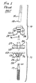
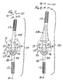
- An example of the PFC SIGMA knee system is shown in FIGS. 1-4. The
system 8 includes a modularfemoral implant 10 and a modulartibial implant 11. The modularfemoral implant 10 includes a distalfemoral component 12, an elongatefemoral stem member 14, abolt 16 and afemoral stem collar 18. The modulartibial implant 11 includes atibial tray 13, atibial insert 15 and an elongatetibial stem extension 17. - The modular
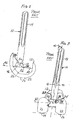
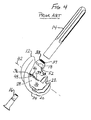
femoral component 12 includes two spacedcondylar portions surfaces surfaces tibial insert 15. As shown in FIGS. 2-3, on the proximal side of thefemoral component 12, the twocondylar portions boss 28. The intercondylar box orboss 28 has a pair of substantiallyvertical side walls mounting platform 34. Theboss mounting platform 34 is generally planar, and has an opening 36 (see FIG. 4) that extends through the boss to define an open channel. Thebolt 16 extends through the channel from the distal side of the femoral component and through theopening 36 to be connected to a female threaded opening in thefemoral stem 14. For clarity, the bolt's external threads are not shown on the drawings, but it should be understood that the proximal end of thebolt 16 is threaded. - The
femoral stem collar 18 has a male portion 37 (FIG. 4) for connection to a distal female threaded end of thestem member 14. A retaining ring is used to hold thecomponents femoral stem member 14,stem collar 18 andfemoral component 12 can be assembled to secure thestem member 14 to thefemoral component 12. With this design, a variety of styles and sizes of stem members and femoral components can be assembled to best suit the patient's anatomy and joint conditions. For example, an implant kit could include a set of different sizes of stem members with outer surfaces adapted for cemented implantation as well as with fluted outer surfaces. - As shown in FIG. 3, when assembled, the
femoral stem member 14 is typically angled in a medial direction. This angle (labelled α) is between theaxis 40 of thefemoral stem member 14 and aline 41 perpendicular to theplane 42 of the seating ormounting platform 34 of the intercondylar boss orbox 28. Theline 41 is also generally co-linear with the central longitudinal axis of thetibial stem extension 17. The angle α corresponds with the valgus angle when the implant assembly is implanted; the valgus angle is defined as the angle between the centre line of the femur and the vertical axis connecting the distal femur and the centre of the femoral head; the centre line of the femur will be aligned with theaxis 40 of thestem member 14, and the vertical axis connecting the distal femur and the centre of the femoral head will be aligned with theline 41. - In the illustrated assembly, the angle α is set by the structure of the
femoral stem collar 18. The femoral stem collar has a superior side orsurface 33 lying in a plane and an inferior side orsurface 35 lying in a plane that is not parallel to the plane of the superior side orsurface 33. Theinferior surface 35 of thecollar 18 is angled, defining an obtuse angle (90° + α) with theaxis 40 of the stem. - For the femoral side, a typical existing implant kit for the PFC SIGMA knee system includes: four sizes of
femoral stem members 14 for use in cemented applications, with diameters of 13 mm and 15 mm and lengths of 90 mm and 130 mm; sixteen sizes of flutedfemoral stem members 14 for non-cemented use, with diameters of 10 mm, 12 mm, 14, mm, 16 mm, 18 mm, 20 mm, 22 mm and 24 mm and lengths of 125 mm and 175 mm in each diameter; two bolts, a standard bolt and one providing a 2 mm anterior-posterior offset; and twostem collars 18 providing angles of 5° and 7° for the angle α, although angles α may be in a typical range of 5 to 9°. A variety of sizes of distalfemoral components 12 are also included in the typical commercial kit. With this variety of modular components, the surgeon can customize the femoral side of the prosthesis to best fit the needs of the individual patient. - Although not shown in FIGS. 1 to 3, the illustrated prior
art stem collar 18 has a central bore to receive part of thebolt 16. The central bore has a central longitudinal axis defining an obtuse angle with at least one of the planes of the superior andinferior sides stem collar 18. - To ensure that the angle α remains in the illustrated orientation, the intercondylar box or
boss 28 typically has a pair ofanti-rotation tabs 46, 48 (see FIGS. 2 and 4) that mate withopposing flats femoral stem collars 18. - As commercially supplied, the
stem members 14 andstem collars 18 are supplied as a unit, connected together prior to being supplied to the surgeon. - As shown in FIG. 1, on the tibial side, the
tibial tray 13 of the modulartibial implant 11 comprises atibial platform 53, with anintegral stem 54 andintegral keels 56 extending between the distal side of the tibial platform and thestem 54. Thetibial platform 53 andstem 54 may have aligned bores to receive a distal extension of thetibial insert 15. In FIG. 1, the illustrated tibial platform and insert are configured for a fixed bearing, although it should be understood that these components could be configured so that theinsert bearing 15 can rotate. - The
distal end 58 of thetibial stem 54 has an interior surface with a threaded female opening (not shown). The threaded female opening mates with a plug (not shown) that can be used where a stem extension is not necessary, and can also be used with the illustratedtibial stem extension 17. Thetibial stem extension 17 has a male threadedend 60 sized and shaped to mate with the threaded female opening at thedistal end 58 of thestem 54. - For the tibial side, a typical existing implant kit for the PFC SIGMA system includes four sizes of
tibial stem extensions 17 for use in cemented applications, with diameters of 13 mm and 15 mm and lengths of 30 mm, 60 mm, 90 mm, 120 mm and 150 mm; twenty-four sizes of flutedtibial stem extensions 17 for non-cemented use, with diameters of 10 mm, 12 mm, 14, mm, 16 mm, 18 mm, 20 mm, 22 mm and 24 mm and lengths of 75 mm, 115 mm and 150 mm in each diameter. A variety of sizes of modulartibial trays 13 andinserts 15 are also included in the typical commercial kit. With this variety of modular components, the surgeon can customize the tibial side of the prosthesis to best fit the needs of the individual patient. - Variations on the knee implant system illustrated in FIGS. 1 to 4 have been disclosed. For example, posterior stabilized mobile bearing knees are disclosed in US-6727723 and US-6443991. Adapters for such knee implant systems are disclosed in US-6171342, US-5824097, US-5782921 and US-5182921. US-5683472 and US-6126693 also disclose features related to knee implant systems.
- Although these known knee implant systems have provided surgeons with great flexibility in meeting patient needs, and the modularity of these systems provides the opportunity to reduce the number of components needed in a surgical kit, these systems still require a substantial number of components.
- The present invention addresses the need for a versatile modular knee implant system that offers surgeons many options to meet the needs of individual patients while reducing the number of components needed to provide these options.
- The present invention therefore provides a modular orthopaedic knee implant system. The system comprises a distal femoral component, a proximal tibial component, an adapter and a stem extension. The distal femoral component has a distal articulating surface and a proximal side. The proximal tibial component has a proximal surface and distal side. The adapter has a proximal end and a distal end; the distal end is sized and shaped to be capable of being connected to the proximal side of the distal femoral component. The stem extension has a connecting end, a body and an opposite end; the connecting end of the stem extension has external threads. The connecting end of the stem extension is sized and shaped to be capable of being selectively connected directly to the proximal tibial component and directly to the adapter.
- The present invention also provides an implantable orthopaedic adapter. The adapter comprises a first end, a second end, a first interior surface, a second interior surface and an outer surface. The first interior surface defines a first bore at the first end. The first bore has a central longitudinal axis. The second interior surface defines a second bore at the second end. The second bore also has a central longitudinal axis. The outer surface of the adapter tapers from one of the ends to the second end. At least one of the interior surfaces is threaded, and the central longitudinal axes of the first bore and second bore intersect at an acute angle.
- The present invention further provides a modular orthopaedic knee implant system comprising a distal femoral component, a proximal tibial component, a tibial bearing, a stem extension, a first femoral adapter, a second femoral adapter and a tapered metaphyseal sleeve. The distal femoral component has a distal articulating surface and a proximal side. The proximal tibial component has a proximal surface and a tibial side. The tibial bearing is carried by the proximal tibial component. The stem extension has a connecting end, a body and an opposite end. The first femoral adapter has a proximal end, a distal end, an interior surface defining a proximal bore and an interior surface defining a distal bore. The proximal bore and distal bore each have a central longitudinal axis. The central longitudinal axis of the distal bore defines an angle with the central longitudinal axis of the proximal bore when viewed in a plane extending in a medial-lateral direction. The second femoral adapter has a proximal end, a distal end, an interior surface defining a proximal bore and an interior surface defining a distal bore. The proximal bore has a central longitudinal axis and the distal bore has a central longitudinal axis of the proximal bore. The central longitudinal axis of the distal bore defines an angle with the central longitudinal axis of the proximal bore when viewed in a plane extending in a medial-lateral direction; this angle of the second femoral adapter is different from the corresponding angle of the first femoral adapter. The tapered metaphyseal component has a proximal end and a distal end, an interior surface defining a distal bore at the distal end and an interior surface defining a proximal bore at the proximal end. The distal bore of the metaphyseal component is sized and shaped to be capable of selectively receiving at least a portion of each of the femoral adapters for selectively mounting the tapered metaphyseal component to the adapter. The connecting end of the stem extension is sized and shaped to be capable of being selectively connected directly to the proximal tibial component, to the proximal end of the first femoral adapter, to the proximal end of the second femoral adapter and to the proximal end of the tapered metaphyseal component.
- Accordingly, in one aspect, the invention provides an n implantable orthopaedic adapter comprising:
- a first end and a second end;
- a first interior surface defining a first bore at the first end, the first bore having a central longitudinal axis;
- a second interior surface defining a second bore at the second end, the second bore having a central longitudinal axis; and
- an outer surface tapering from one of the ends to the second end;
- wherein:
- at least one of the interior surfaces is threaded; and
- the central longitudinal axes of the first bore and second bore intersect at an acute angle.
- In another aspect, the invention provides a modular orthopaedic knee implant system comprising:
- a distal femoral component having a distal articulating surface and a proximal side;
- a proximal tibial component having a proximal surface and a tibial side;
- a tibial bearing to be carried by the proximal tibial component;
- a stem extension having a connecting end, a body and an opposite end;
- a first femoral adapter having a proximal end, a distal end, an interior surface defining a proximal bore having a central longitudinal axis, an interior surface defining a distal bore having a central longitudinal axis defining an angle with the central longitudinal axis of the proximal bore when viewed in a plane extending in a medial-lateral direction;
- a second femoral adapter having a proximal end, a distal end, an interior surface defining a proximal bore having a central longitudinal axis, an interior surface defining a distal bore having a central longitudinal axis defining an angle with the central longitudinal axis of the proximal bore when viewed in a plane extending in a medial-lateral direction, the angle of the second femoral adapter being different from the angle of the first femoral adapter; and
- a tapered metaphyseal component having a proximal end and a distal end, an interior surface defining a distal bore at the distal end, an interior surface defining a proximal bore at the proximal end, wherein the distal bore is sized and shaped to be capable of selectively receiving at least a portion of each of the femoral adapters for selectively mounting the tapered metaphyseal component to the adapter;
- In a further aspect, the invention provides a modular orthopaedic knee implant system comprising:
- a distal femoral component having a distal articulating surface and a proximal side;
- a proximal tibial component having a proximal surface and distal side;
- an adapter having a proximal end and a distal end, wherein the distal end is sized and shaped to be capable of being connected to the proximal side of the distal femoral component; and
- a stem extension having a connecting end, a body and an opposite end, the connecting end having external threads;
- Embodiments of the invention will now be described by way of example with reference to the accompanying drawings, in which:
- FIG. 1 is an exploded view of a prior art modular orthopaedic knee implant system;
- FIG. 2 is a lateral side view of the assembled femoral components of the modular orthopaedic knee implant system of FIG. 1;
- FIG. 3 is a posterior view of the assembled femoral components of the modular orthopaedic knee implant system of FIGS. 1-2;
- FIG. 4 is an exploded perspective view of the femoral components of the modular orthopaedic knee implant system of FIGS. 1-3;
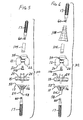
- FIG. 5 is an exploded view of an example of a modular orthopaedic knee implant incorporating the teachings of the present invention;
- FIG. 6 is an exploded view of another example of a modular orthopaedic knee implant incorporating the teachings of the present invention;
- FIG. 7 is a posterior view of the assembled knee implant of FIG. 5;
- FIG. 8 is a posterior view of the assembled knee implant of FIG. 6;
- FIG. 9 is a medial or lateral view of an example of an orthopaedic adapter incorporating the teachings of the present invention;
- FIG. 10 is a distal end view of the orthopaedic adapter of FIGS. 9 and 11-12, taken along line 10-10 of FIG. 11;
- FIG. 11 is an anterior or posterior view of the orthopaedic adapter of FIGS. 9-10 and 12;
- FIG. 12 is a cross-section of the orthopaedic adapter of FIGS. 9-11, taken along line 12-12 of FIG. 9;
- FIG. 13 is a cross-section of an exemplary metaphyseal sleeve that may be used with the implant and system of the present invention;
- FIG. 14 is a side view of an example of a bolt that may be used with the orthopaedic adapter of FIGS. 9-12;
- FIG. 15 is a cross-section of the bolt of FIG. 14, taken along line 15-15 of FIG. 14;
- FIG. 16 is an end view of the bolt of FIGS. 14-15;
- FIG. 17 is a view of an example of modular orthopaedic knee implant system or kit incorporating the teachings of the present invention;
- FIG. 18 is a medial or lateral view of another example of an orthopaedic adapter that can be included in the modular orthopaedic knee implant system or kit of the present invention to allow for anterior and posterior offset of the femoral stem;
- FIG. 19 is a distal end view of the orthopaedic adapter of FIGS. 18, 20-21 and 23, taken along line 19-19 of FIG. 20;
- FIG. 20 is an anterior or posterior view of the orthopaedic adapter of FIGS. 18-19, 21 and 23;
- FIG. 21 is a cross-section of the orthopaedic adapter of FIGS. 18-20 and 23, taken along line 21-21 of FIG. 18;
- FIG. 22 is an exploded view of the orthopaedic adapter of FIGS. 9-12 in combination with a stem extension, femoral implant component and bolt, with parts shown in cross-section through an anterior-posterior or sagittal plane; and
- FIG. 23 is an exploded view of the orthopaedic adapter of FIGS. 18-21 in combination with a stem extension, femoral implant component and bolt, with parts shown in cross-section through an anterior-posterior or sagittal plane;
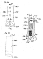
- FIG. 24 is a medial or lateral view of another example of an orthopaedic adapter that can be included in the modular orthopaedic knee implant system or kit of the present invention to allow for anterior and posterior offset of the femoral stem;
- FIG. 25 is an anterior or posterior view of the orthopaedic adapter of FIG. 24; and
- FIG. 26 is a cross-section of the orthopaedic adapter of FIGS. 24-25, taken along line 26-26 of FIG. 24.
- Referring to the drawings, FIGS. 5-6 show in exploded views two exemplary
orthopaedic knee implants knee implants - Each of the knee implants shown in FIGS. 5-8 includes: a
femoral adapter 104; a distalfemoral component 12; afemoral adapter bolt 106; atibial insert 15; atibial tray 13; and two stemextensions 17. As indicated by the use of the same reference numbers for the distalfemoral component 12,tibial insert 15,tibial tray 13, and two stemextensions 17, these components of the implants may have the same features as the PFC SIGMA system described above with reference to FIGS. 1-4. - However, unlike the system shown in FIGS. 1-4, the
knee implants stem extensions 17 previously used only for the tibial portion of the implant can also be used for the femoral side, substantially reducing the number of components needed. - The
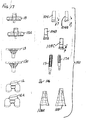
knee implant 102 illustrated in FIGS. 6 and 8 includes an additional component, ametaphyseal sleeve 108. Themetaphyseal sleeve 108 may have features such as those disclosed in US-A-2005/107883. Alternatively, themetaphyseal sleeve 108 may have features of commercially available sleeves which are available as part of the LCS system discussed above. - As illustrated in FIG. 13, the
metaphyseal sleeve 108 may include a Morse taper bore 109 at itsdistal end 110 and a threaded female bore 111 at or near itsproximal end 112. Theouter surface 113 of the illustratedsleeve 108 has a stepped configuration, tapering from thedistal end 110 toward theproximal end 112. Theouter surface 113 of the sleeve may be partially porous, or may be fully porous as disclosed in US-A-2005/107883. - The
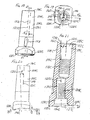
metaphyseal sleeve 108 is selectively mountable on thefemoral adapter 104. As shown in FIGS. 9 and 11-12, the outer surface of thefemoral adapter 104 includes a taperedportion 114 at its proximal end. The taperedportion 114 of the outer surface is sized and shaped to frictionally lock with the Morse taper female bore 109 of themetaphyseal sleeve 108. Typically, the taperedportion 114 of the outer surface would taper at an angle of 5 to 8° to define a Morse taper post to be received within and lock with the Morse taper bore 109 of themetaphyseal sleeve 108. - As shown in FIG. 12, at its
proximal end 116, thefemoral adapter 104 has a proximal female bore 115 with interior walls defining a lead-inchamfer 117, acylindrical portion 119 and a threadedfemale portion 118. The threadedfemale portion 118 is sized and shaped to receive and engage the threadedmale end 60 of thestem extension 17. The threads may be formed so as to lock together on engagement, for example using a thread assembly such as that sold under the trade mark SPIRALOCK. The proximalfemale bore 115 has a central longitudinal axis 121. - As shown in FIG. 12, at or near its
distal end 122, thefemoral adapter 104 has a distal female bore 123 with interior walls defining achamfer portion 127, acylindrical portion 129 and a threadedfemale portion 124. The threadedfemale portion 124 is sized and shaped to receive and engage the threadedmale end 126 of thefemoral bolt 106, shown in FIGS. 14-15. These threads may also be formed so as to lock together on engagement. The distal female bore 123 has a centrallongitudinal axis 125 that intersects the central longitudinal axis 121 of the proximal female bore 115 at an angle β. - The
femoral adapter 104 has an annular boss-engagingsurface 128 at itsdistal end 122. This boss-engagingsurface 128 may be generally perpendicular to theaxis 125 of the distalfemale bore 123. In the illustrated embodiment, the boss-engagingsurface 128 is canted at an angle δ to atransverse plane 130. Thetransverse plane 130 is perpendicular to the axis 121 of the proximalfemale bore 115. In the illustrated embodiment, the angles β and δ are equal to each other, and are about 5°. Alternatively, the angles β and δ could be about 3° or 7°. In the embodiment where δ is 7°, theaxis 125 of the distal female bore 123 may be tilted at an angle of 2° relative to the boss-engagingsurface 128. - When assembled, the boss-engaging
surface 128 of thefemoral adapter 104 engages the mountingplatform 34 of the intercondylar boss orbox 28 of thefemoral component 12. Thus, the angles β and δ set the valgus angle of thefemoral adapter 104, and thereby set the valgus angle of the femoral stem extension, as discussed in more detail below. The distal end of thefemoral adaptor 104 may have features of thefemoral stem collar 18 of the existing PFC SIGMA system. - To lock the
femoral adapter 104 to the distalfemoral component 12, thebolt 106 of FIGS. 14-15 is used in the illustrated embodiments. In addition to the threadedmale end 126, thebolt 106 includes a head with acylindrical portion 140 and atapered portion 142. Thecylindrical portion 140 and taperedportion 142 of the bolt head are sized and shaped to be received within thecylindrical portion 129 andchamfer portion 127 of the distal female bore 123 of thefemoral adapter 104 and theopening 36 of the mountingplatform 34 of thefemoral component 12. The taperedportion 142 of the bolt may be frustoconical or could be spherically shaped as disclosed in US-5556433. - An example of a
knee implant system 150 incorporating the above-described components is illustrated in FIG. 17. The illustratedknee implant system 150 includes a plurality of distalfemoral components 12, 12A of different sizes; a plurality oftibial trays 13, 13A of different sizes; a plurality oftibial insert bearings metaphyseal sleeves stem extensions femoral adapters knee implant system 150 would also include additional femoral andtibial components system 150, threefemoral adapters system 150 is that one set of stem extensions can be used on both the tibial and femoral sides. Accordingly, the number of stem extensions provided in the kit or system can be reduced without reducing the options available to the surgeon. With the inclusion ofmetaphyseal sleeves - To provide further options to suit individual patient needs, the knee implant system or
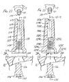
kit 150 could include an anterior-posterior offset femoral adapter 104C illustrated in FIGS. 18-21 and 23. Like thefemoral adapter 104 described above with reference to FIGS. 9-12, the outer surface of the anterior-posterior offset femoral adapter 104C has a taperedportion 114C at its proximal end, sized and shaped to frictionally lock with a Morse taper female bore 109 of a metaphyseal sleeve 108 (see FIG. 13). And like the embodiment of FIGS. 9-12, the anterior-posterior offset femoral adapter 104C has a proximal female bore 115C (see FIGS. 21 and 23) at or near itsproximal end 116C with interior walls defining a lead in chamfer 117C, acylindrical portion 119C and a threadedfemale portion 118C. The threadedfemale portion 118C is sized and shaped to receive and engage the threadedmale end 60 of thestem extension 17. - At or near its
distal end 122C, the anterior-posterior offset femoral adapter 104C has a distal female bore 123C (see FIGS. 21 and 23) with interior walls defining a lead-in chamfer portion 127C, acylindrical portion 129C and a threadedfemale portion 124C. The threadedfemale portion 124C is sized and shaped to receive the threadedmale end 126 of thefemoral bolt 106. - The distal
female bore 123C of the anterior-posterior offset femoral adapter has a centrallongitudinal axis 125C. As in the embodiment of FIGS. 9-12, thisaxis 125C of the distalfemale bore 123C defines an angle β with the centrallongitudinal axis 121C of the proximal female bore 115C (see FIG. 21) when viewed in a central medial-lateral or coronal plane (labelled 152 in FIGS. 10 and 19). Like the embodiment of FIGS. 9-12, the boss-engaging surface 128C is inclined at an angle δ to atransverse plane 130C when viewed in a medial-lateral or coronal plane (labelled 152 in FIGS. 10 and 19). As in the embodiment of FIGS. 9 to 12, the angles β and δ could be, for example, 0°, 3°, 5° or a kit could include anterior-posterior offset femoral adapters with all of these angles. It should be understood that the angles β and δ also correspond with the valgus angle, shown as angle α in FIGS. 3 and 7 to 8. - However, the embodiments of FIGS. 9-12 and FIGS. 18-21 differ when viewed in an anterior-posterior or sagittal plane (labelled 154 and 154C in FIGS. 10 and 19), as can be seen from a comparison of FIGS. 22 and 23. The
femoral adapters 104 and 104C are shown in FIGS. 22 and 23 in exploded views in combination with astem extension 17,femoral implant component 12 andbolt 106. FIG. 22 illustrates thefemoral adapter 104 of FIGS. 9-12 and FIG. 23 illustrates the femoral adapter 104C of FIGS. 18-21. - As can be seen in FIG. 22, in the case of the
femoral adapter 104 of FIGS. 9-12, the centrallongitudinal axis 131 of the threadedend 60 of thestem extension 17 is aligned co-linearly with the central longitudinal axis 121 of the proximal female threadedbore 115, the centrallongitudinal axis 125 of the distal threadedfemale bore 123 and the centrallongitudinal axis 155 of thebolt 106 when viewed in an anterior-posterior or sagittal plane. Thus, as shown in FIG. 10 for the femoral adapter of FIGS. 9-12, the centrallongitudinal axes 121, 125 of both the proximal female threadedbore 115 and the distal female threaded bore 123 lie in the same central medial-lateral orcoronal plane 152. - But as can be seen in FIG. 23, in the case of the anterior-posterior offset femoral adapter 104C of FIGS. 18-21, the central
longitudinal axis 131 of the threadedend 60 of thestem extension 17 is aligned co-linearly only with the centrallongitudinal axis 121C of the proximal female threaded bore 115C. The centrallongitudinal axis 125C of the distal female bore 123C and the centrallongitudinal axis 155 of thebolt 106 are co-linearly aligned, but are offset by a distance "d" (see FIGS. 18-19 and 23) from the centrallongitudinal axes end 60 of theextension 17 and the proximal female bore 115C. This distance "d" equates with an offset in the anterior-posterior direction. FIG. 19 illustrates this distance "d" as the distance between the central medial-lateral orcoronal plane 152 of the centrallongitudinal axis 121C of the proximal female bore 115C and the parallelcoronal plane 153 of the centrallongitudinal axis 125C of the distal female bore 123C. Thus, using the anterior-posterior offset femoral adapter of the embodiment of FIGS. 18-21 and 23, the position of thestem extension 17 can be offset in either the anterior or posterior direction. A typical example of a dimension for distance "d" is on the order of 2 mm. - To provide an offset in the anterior direction, the anterior-posterior offset femoral adapter 104C would be used on the left knee. To provide an offset in the posterior direction, the anterior-posterior femoral adapter 104C would be used on the right knee. To allow for such offsets in both the anterior and posterior directions for both knees, a typical surgical kit would include an anterior-posterior femoral adapter 104C as illustrated in FIGS. 18-21 and 23 and would also include an anterior-posterior femoral adapter similar to that illustrated in FIGS. 18-21 and 23 but with the position of the central longitudinal axis of the distal female bore offset to the left of the central axis of the proximal female bore, instead of to the right as shown in FIG. 23.
- Another embodiment of a femoral adapter is illustrated in FIGS. 24-26 at 104D. The femoral adapter 104D of this embodiment is similar to the femoral adapter 104C of FIGS. 18-21, except that the exterior surfaces of the
adapters 104, 104C, 104D are shaped slightly differently. In FIGS. 24-26, the reference numbers used for the embodiments of FIGS. 9-12 and 18-21 have also been used, followed by the letter "D", to indicate similar features or portions of the adapters. - In the embodiments of FIGS. 9-12 and 18-21, the
femoral adapters 104, 104C include a cylindrical outer surface 160, 160C between the taperedouter surface proximal end portion distal end distal end 122D; there is no intermediate cylindrically shaped portion. The angle of the tapered outer surface 114D in the embodiment of FIGS. 24-26 may be sized and shaped to frictionally lock with the Morse taper female bore 109 of themetaphyseal sleeve 108. - Although the embodiment of FIGS. 24-26 is illustrated with an anterior-posterior offset similar to the adapter 104C of FIGS. 18-21, it should be understood that an adapter with the extended tapered exterior surface of FIGS. 24-26 could have the features of the
adapter 104 of FIGS. 8-12 so that no anterior-posterior offset is provided. It should also be understood that a surgical kit or knee implant system could include several adapters having the exterior surface shape shown in FIGS. 24-26. - All of the components of the illustrated
knee implant system 150 can be made of standard materials, such as titanium or a cobalt-chrome alloy. The components can be made and finished in standard ways, and may include porous coatings where desired. - As is typical in known orthopaedic implant systems, a number of trials would also be included in the kit to give the surgeon the opportunity to evaluate the implants selected before permanently implanting the implant components.
- In use, the surgeon will prepare the patient's femur and tibia in a standard manner. If the surgeon determines that it is desirable to include a
stem extension 17 on either the tibial side or femoral side, an appropriately sized and finished stemextension 17 can be selected from the kit or system. For the tibial side, the surgeon can simply thread the stem extension onto the distal end of thetibial tray 13. For the femoral side, if a stem extension is desired the surgeon would select the appropriatefemoral adapter 104, 104C or 104D and affix the selected adapter to the mountingsurface 34 of the intercondylar box orboss 28 with thebolt 106. If the patient's condition does not warrant use of ametaphyseal sleeve 108, the surgeon can thread an appropriately sized and finished stemextension 17 onto the proximal end of thefemoral adapter 104, 104C, 104D. If the patient's condition warrants use of ametaphyseal sleeve 108, the surgeon can fix an appropriately sized and finishedsleeve 108 onto thefemoral adapter 104, 104C, 104D through the Morse taper connection and then can thread an appropriately sized and finished stemextension 17 onto the proximal end of themetaphyseal sleeve 108.
wherein the connecting end of the stem extension is sized and shaped to be capable of being selectively connected directly to the proximal tibial component, to the proximal end of the first femoral adapter, to the proximal end of the second femoral adapter and to the proximal end of the tapered metaphyseal component.
wherein the connecting end of the stem extension is sized and shaped to be capable of being selectively connected directly to the proximal tibial component and directly to the adapter.
Claims (11)
- An implantable orthopaedic adapter comprising:a first end and a second end;a first interior surface defining a first bore at the first end, the first bore having a central longitudinal axis;a second interior surface defining a second bore at the second end, the second bore having a central longitudinal axis; andan outer surface tapering from one of the ends to the second end;wherein:at least one of the interior surfaces is threaded; andthe central longitudinal axes of the first bore and second bore intersect at an acute angle.
- An adapter as claimed in claim 1 including a first end surface lying in one plane and a second end surface lying in a non-parallel plane.
- A modular orthopaedic knee implant system comprising:a distal femoral component having a distal articulating surface and a proximal side;a proximal tibial component having a proximal surface and a tibial side;a tibial bearing to be carried by the proximal tibial component;a stem extension having a connecting end, a body and an opposite end;a first femoral adapter having a proximal end, a distal end, an interior surface defining a proximal bore having a central longitudinal axis, an interior surface defining a distal bore having a central longitudinal axis defining an angle with the central longitudinal axis of the proximal bore when viewed in a plane extending in a medial-lateral direction;a second femoral adapter having a proximal end, a distal end, an interior surface defining a proximal bore having a central longitudinal axis, an interior surface defining a distal bore having a central longitudinal axis defining an angle with the central longitudinal axis of the proximal bore when viewed in a plane extending in a medial-lateral direction, the angle of the second femoral adapter being different from the angle of the first femoral adapter; anda tapered metaphyseal component having a proximal end and a distal end, an interior surface defining a distal bore at the distal end, an interior surface defining a proximal bore at the proximal end, wherein the distal bore is sized and shaped to be capable of selectively receiving at least a portion of each of the femoral adapters for selectively mounting the tapered metaphyseal component to the adapter;
wherein the connecting end of the stem extension is sized and shaped to be capable of being selectively connected directly to the proximal tibial component, to the proximal end of the first femoral adapter, to the proximal end of the second femoral adapter and to the proximal end of the tapered metaphyseal component. - A system as claimed in claim 3 wherein the central longitudinal axis of the distal bore of the first femoral adapter and the central longitudinal axis of the proximal bore of the first femoral adapter are co-linear when viewed in a plane extending in an anterior-posterior direction.
- A system as claimed in claim 3 wherein the central longitudinal axis of the distal bore of the second femoral adapter is offset from and parallel to the central longitudinal axis of the proximal bore of the second femoral adapter when viewed in a plane extending in an anterior-posterior direction.
- A system as claimed in claim 5 wherein the central longitudinal axis of the distal bore of the first femoral adapter and the central longitudinal axis of the proximal bore of the first femoral adapter are co-linear when viewed in a plane extending in an anterior-posterior direction.
- A modular orthopaedic knee implant system comprising:a distal femoral component having a distal articulating surface and a proximal side;a proximal tibial component having a proximal surface and distal side;an adapter having a proximal end and a distal end, wherein the distal end is sized and shaped to be capable of being connected to the proximal side of the distal femoral component; anda stem extension having a connecting end, a body and an opposite end, the connecting end having external threads;
wherein the connecting end of the stem extension is sized and shaped to be capable of being selectively connected directly to the proximal tibial component and directly to the adapter. - A system as claimed in claim 7 which includes a tapered metaphyseal component having a proximal end and a distal end, an interior surface defining a distal bore at the distal end, an interior surface defining a proximal bore at the proximal end, wherein the distal bore is sized and shaped to be capable of receiving at least a portion of the adapter for mounting the tapered metaphyseal component to the adapter, and the proximal bore is sized and shaped to be capable being connected to the connecting end of the stem extension.
- A system as claimed in claim 8 wherein the adapter has an outer surface and wherein the outer surface of the adapter and the distal bore of the tapered metaphyseal component are sized and shaped to frictionally lock together when assembled.
- A system as claimed in claim 8 wherein the adapter includes:a distal interior surface defining a distal bore at the distal end of the adapter, the distal bore having a central longitudinal axis; anda proximal interior surface defining a proximal bore at the proximal end of the adapter, the proximal bore having a central longitudinal axis defining an acute angle with the central longitudinal axis of the distal bore when viewed in a plane extending in a medial-lateral direction;
wherein the proximal interior surface of the proximal bore is threaded. - A system as claimed in claim 8 which includes a second adapter having a proximal end and a distal end, wherein the distal end is sized and shaped to be capable of being connected to the proximal side of the distal femoral component, wherein each adapter has a proximal end surface lying in one plane and a distal end surface lying in a non-parallel plane, and wherein the planes of the distal end surfaces of the two adapters define different angles with the planes of the proximal end surfaces.
Applications Claiming Priority (1)
| Application Number | Priority Date | Filing Date | Title |
|---|---|---|---|
| US10/912,325 US8366782B2 (en) | 2004-08-05 | 2004-08-05 | Modular orthopaedic implant system with multi-use stems |
Publications (3)
| Publication Number | Publication Date |
|---|---|
| EP1623686A2 true EP1623686A2 (en) | 2006-02-08 |
| EP1623686A3 EP1623686A3 (en) | 2011-03-30 |
| EP1623686B1 EP1623686B1 (en) | 2012-08-22 |
Family
ID=35395746
Family Applications (1)
| Application Number | Title | Priority Date | Filing Date |
|---|---|---|---|
| EP05254634A Active EP1623686B1 (en) | 2004-08-05 | 2005-07-26 | Modular orthopaedic implant system |
Country Status (4)
| Country | Link |
|---|---|
| US (1) | US8366782B2 (en) |
| EP (1) | EP1623686B1 (en) |
| JP (1) | JP4642586B2 (en) |
| AU (1) | AU2005203297B2 (en) |
Cited By (12)
| Publication number | Priority date | Publication date | Assignee | Title |
|---|---|---|---|---|
| EP1913902A1 (en) | 2006-10-19 | 2008-04-23 | DePuy Products, Inc. | Bowed femoral sleeve |
| EP2042127A1 (en) | 2007-09-27 | 2009-04-01 | DePuy Products, Inc. | Knee orthopaedic implant |
| EP2046248A1 (en) * | 2006-07-18 | 2009-04-15 | Biomet Manufacturing Corp. | Method and apparatus for a knee implant |
| US8366782B2 (en) | 2004-08-05 | 2013-02-05 | Depuy Products, Inc. | Modular orthopaedic implant system with multi-use stems |
| US8540775B2 (en) | 2007-06-11 | 2013-09-24 | Aesculap Ag | Modular implant part and knee joint prosthesis |
| EP2777620A1 (en) * | 2013-03-14 | 2014-09-17 | DePuy (Ireland) | Orthopaedic knee prosthesis |
| US8998996B2 (en) | 2012-09-20 | 2015-04-07 | Depuy (Ireland) | Knee prosthesis system with standard and distal offset joint line |
| US9044328B2 (en) | 2008-03-07 | 2015-06-02 | Aesculap Ag | Medical implant and knee joint endoprosthesis |
| US9320603B2 (en) | 2012-09-20 | 2016-04-26 | Depuy (Ireland) | Surgical instrument system with multiple lengths of broaches sharing a common geometry |
| US9532879B2 (en) | 2012-09-20 | 2017-01-03 | Depuy Ireland Unlimited Company | Femoral knee prosthesis system with augments and multiple lengths of sleeves sharing a common geometry |
| WO2019171139A1 (en) * | 2018-03-07 | 2019-09-12 | Cossington Limited | Temporary spacer device for joints of the human body |
| EP4344680A1 (en) * | 2022-09-28 | 2024-04-03 | Wright Medical Technology, Inc. | Implants with modular stems with tension/compression mechanisms |
Families Citing this family (77)
| Publication number | Priority date | Publication date | Assignee | Title |
|---|---|---|---|---|
| JP2008500140A (en) * | 2004-05-21 | 2008-01-10 | メイヤーズ サージカル ソリューションズ, エルエルシー | Fracture fixation and site stabilization system |
| AU2005317184B2 (en) * | 2004-12-17 | 2011-10-13 | Depuy Products, Inc. | Modular implant system and method with diaphyseal implant and adapter |
| US7867282B2 (en) * | 2004-12-17 | 2011-01-11 | Depuy Products, Inc. | Modular implant system and method with diaphyseal implant and adapter |
| WO2010037038A2 (en) | 2008-09-26 | 2010-04-01 | Sonoma Orthopedic Products, Inc. | Bone fixation device, tools and methods |
| US9060820B2 (en) | 2005-05-18 | 2015-06-23 | Sonoma Orthopedic Products, Inc. | Segmented intramedullary fracture fixation devices and methods |
| US8961516B2 (en) | 2005-05-18 | 2015-02-24 | Sonoma Orthopedic Products, Inc. | Straight intramedullary fracture fixation devices and methods |
| US20070005141A1 (en) | 2005-06-30 | 2007-01-04 | Jason Sherman | Apparatus, system, and method for transcutaneously transferring energy |
| US7780613B2 (en) | 2005-06-30 | 2010-08-24 | Depuy Products, Inc. | Apparatus, system, and method for transcutaneously transferring energy |
| WO2007114841A1 (en) * | 2006-04-04 | 2007-10-11 | Smith & Nephew, Inc. | Trial coupler systems and methods |
| US8015024B2 (en) | 2006-04-07 | 2011-09-06 | Depuy Products, Inc. | System and method for managing patient-related data |
| US8075627B2 (en) | 2006-04-07 | 2011-12-13 | Depuy Products, Inc. | System and method for transmitting orthopaedic implant data |
| US8632464B2 (en) | 2006-09-11 | 2014-01-21 | DePuy Synthes Products, LLC | System and method for monitoring orthopaedic implant data |
| US20080091271A1 (en) * | 2006-10-13 | 2008-04-17 | Bonitati John A | Mobile/fixed prosthetic knee systems |
| CA2670263A1 (en) | 2006-11-22 | 2008-05-29 | Sonoma Orthopedic Products, Inc. | Fracture fixation device, tools and methods |
| US8187280B2 (en) | 2007-10-10 | 2012-05-29 | Biomet Manufacturing Corp. | Knee joint prosthesis system and method for implantation |
| US8328873B2 (en) | 2007-01-10 | 2012-12-11 | Biomet Manufacturing Corp. | Knee joint prosthesis system and method for implantation |
| US8562616B2 (en) | 2007-10-10 | 2013-10-22 | Biomet Manufacturing, Llc | Knee joint prosthesis system and method for implantation |
| US8163028B2 (en) | 2007-01-10 | 2012-04-24 | Biomet Manufacturing Corp. | Knee joint prosthesis system and method for implantation |
| JP5448842B2 (en) | 2007-01-10 | 2014-03-19 | バイオメト マニファクチャリング コーポレイション | Knee joint prosthesis system and implantation method |
| US8430879B2 (en) * | 2007-03-22 | 2013-04-30 | Sonoma Orthopedic Products, Inc. | Segmented intramedullary structure |
| US8147557B2 (en) | 2007-03-30 | 2012-04-03 | Depuy Products, Inc. | Mobile bearing insert having offset dwell point |
| US8142510B2 (en) | 2007-03-30 | 2012-03-27 | Depuy Products, Inc. | Mobile bearing assembly having a non-planar interface |
| US8147558B2 (en) | 2007-03-30 | 2012-04-03 | Depuy Products, Inc. | Mobile bearing assembly having multiple articulation interfaces |
| US8328874B2 (en) | 2007-03-30 | 2012-12-11 | Depuy Products, Inc. | Mobile bearing assembly |
| US8764841B2 (en) | 2007-03-30 | 2014-07-01 | DePuy Synthes Products, LLC | Mobile bearing assembly having a closed track |
| US8177849B2 (en) * | 2007-05-07 | 2012-05-15 | Zimmer, Inc. | Methods and apparatuses for attaching tissue to orthopaedic implants |
| US8080064B2 (en) * | 2007-06-29 | 2011-12-20 | Depuy Products, Inc. | Tibial tray assembly having a wireless communication device |
| US7993407B2 (en) * | 2007-06-29 | 2011-08-09 | Depuy Products, Inc. | Orthopaedic prosthesis having a positionable stem |
| DE202007009620U1 (en) * | 2007-07-09 | 2007-11-22 | Zrinski Ag | Articulated prosthesis with an anti-twist device |
| DE202007009619U1 (en) * | 2007-07-09 | 2007-11-22 | Zrinski Ag | Articulated prosthesis with expandable shaft |
| US8632600B2 (en) | 2007-09-25 | 2014-01-21 | Depuy (Ireland) | Prosthesis with modular extensions |
| US8128703B2 (en) | 2007-09-28 | 2012-03-06 | Depuy Products, Inc. | Fixed-bearing knee prosthesis having interchangeable components |
| US9204967B2 (en) | 2007-09-28 | 2015-12-08 | Depuy (Ireland) | Fixed-bearing knee prosthesis having interchangeable components |
| US20100114323A1 (en) | 2008-10-31 | 2010-05-06 | Depuy Products, Inc. | Knee prosthesis kit with winged sleeves and milling guide |
| US8454706B2 (en) | 2009-02-25 | 2013-06-04 | Brian C. de Beaubien | Antibiotic delivery system and method for treating an infected synovial joint during re-implantation of an orthopedic prosthesis |
| US9918842B1 (en) * | 2009-12-16 | 2018-03-20 | Signal Medical Corporation | Knee system |
| US9011547B2 (en) * | 2010-01-21 | 2015-04-21 | Depuy (Ireland) | Knee prosthesis system |
| US8932364B2 (en) * | 2010-07-14 | 2015-01-13 | Howmedica Osteonics Corp. | Prosthetic knee void filers with splined fixation |
| US9381090B2 (en) | 2010-07-24 | 2016-07-05 | Zimmer, Inc. | Asymmetric tibial components for a knee prosthesis |
| US8764840B2 (en) | 2010-07-24 | 2014-07-01 | Zimmer, Inc. | Tibial prosthesis |
| EP3034042B1 (en) | 2010-07-24 | 2017-06-28 | Zimmer, Inc. | Asymmetric tibial components for a knee prosthesis |
| US8591594B2 (en) | 2010-09-10 | 2013-11-26 | Zimmer, Inc. | Motion facilitating tibial components for a knee prosthesis |
| US8317870B2 (en) | 2010-09-30 | 2012-11-27 | Depuy Products, Inc. | Tibial component of a knee prosthesis having an angled cement pocket |
| US8287601B2 (en) | 2010-09-30 | 2012-10-16 | Depuy Products, Inc. | Femoral component of a knee prosthesis having an angled cement pocket |
| US8603101B2 (en) | 2010-12-17 | 2013-12-10 | Zimmer, Inc. | Provisional tibial prosthesis system |
| CN104066402B (en) | 2011-11-18 | 2016-05-04 | 捷迈有限公司 | For the shin bone support member with improved articulation feature of knee-joint prosthesis |
| ES2585838T3 (en) | 2011-11-21 | 2016-10-10 | Zimmer, Inc. | Tibial base plate with asymmetric placement of fixing structures |
| EP2787930B1 (en) * | 2011-12-07 | 2018-10-03 | Smith&Nephew, Inc. | Posterior stabilized insert trial with adjustable post |
| US9452054B2 (en) * | 2012-03-06 | 2016-09-27 | University Of Cape Town | Rotating hinge knee prosthesis |
| US8721733B2 (en) | 2012-05-14 | 2014-05-13 | Depuy (Ireland) | Prosthesis kit with finned sleeve |
| US20140081410A1 (en) * | 2012-09-20 | 2014-03-20 | Jay R. Lieberman | Modular knee prosthesis system with multiple lengths of sleeves sharing a common geometry |
| US9603649B2 (en) | 2013-03-15 | 2017-03-28 | Depuy Ireland Unlimited Company | Instruments for use in disassembling implants |
| US9138321B2 (en) | 2013-03-15 | 2015-09-22 | Depuy (Ireland) | Prosthetic components with secondary retention |
| US9101479B2 (en) * | 2013-03-15 | 2015-08-11 | Depuy (Ireland) | Prosthetic components and methods for joint line access |
| US9144498B2 (en) | 2013-03-15 | 2015-09-29 | Depuy (Ireland) | Modular knee prosthesis system for use with different load requirements |
| US9925052B2 (en) | 2013-08-30 | 2018-03-27 | Zimmer, Inc. | Method for optimizing implant designs |
| US9770278B2 (en) | 2014-01-17 | 2017-09-26 | Arthrex, Inc. | Dual tip guide wire |
| US10874496B2 (en) | 2014-06-25 | 2020-12-29 | Canary Medical Inc. | Devices, systems and methods for using and monitoring implants |
| CA2992263A1 (en) | 2014-06-25 | 2015-12-30 | Canary Medical Inc. | Devices, systems and methods for using and monitoring tubes in body passageways |
| US11596347B2 (en) | 2014-06-25 | 2023-03-07 | Canary Medical Switzerland Ag | Devices, systems and methods for using and monitoring orthopedic hardware |
| US20180125365A1 (en) | 2014-09-17 | 2018-05-10 | Canary Medical Inc. | Devices, systems and methods for using and monitoring medical devices |
| US9814499B2 (en) | 2014-09-30 | 2017-11-14 | Arthrex, Inc. | Intramedullary fracture fixation devices and methods |
| US9943413B2 (en) | 2015-01-30 | 2018-04-17 | Russell Nevins | Revision stepped tibial implant |
| US10433965B2 (en) * | 2015-06-17 | 2019-10-08 | Joint Purification Systems Llc | Total joint replacement infection control devices and methods |
| US9668883B2 (en) * | 2015-08-19 | 2017-06-06 | Depuy Ireland Unlimited Company | Trial kit for knee prosthesis system |
| CN108135701B (en) | 2015-09-21 | 2019-12-24 | 捷迈有限公司 | Prosthesis system including tibial bearing component |
| US11191479B2 (en) | 2016-03-23 | 2021-12-07 | Canary Medical Inc. | Implantable reporting processor for an alert implant |
| MX2018011544A (en) | 2016-03-23 | 2019-06-24 | Canary Medical Inc | Implantable reporting processor for an alert implant. |
| US10182830B2 (en) | 2016-04-05 | 2019-01-22 | Arthrology Consulting, Llc | Modular total knee arthroplasty system and method |
| US10675153B2 (en) | 2017-03-10 | 2020-06-09 | Zimmer, Inc. | Tibial prosthesis with tibial bearing component securing feature |
| CA3063415C (en) | 2017-05-12 | 2021-10-19 | Zimmer, Inc. | Femoral prostheses with upsizing and downsizing capabilities |
| US11426282B2 (en) | 2017-11-16 | 2022-08-30 | Zimmer, Inc. | Implants for adding joint inclination to a knee arthroplasty |
| US10835380B2 (en) | 2018-04-30 | 2020-11-17 | Zimmer, Inc. | Posterior stabilized prosthesis system |
| CN109077834A (en) * | 2018-09-29 | 2018-12-25 | 北京爱康宜诚医疗器材有限公司 | Tibial plateau prosthesis assembly |
| WO2021022047A1 (en) * | 2019-08-01 | 2021-02-04 | Smith & Nephew, Inc. | Orthopaedic implant |
| US11660199B2 (en) | 2020-01-29 | 2023-05-30 | Encore Medical, L.P. | Modular knee augment cones |
| CN112618114A (en) * | 2020-11-27 | 2021-04-09 | 北京市春立正达医疗器械股份有限公司 | Tantalum metal trabecular femoral condyle prosthesis and knee joint replacement body |
Citations (10)
| Publication number | Priority date | Publication date | Assignee | Title |
|---|---|---|---|---|
| US5182921A (en) | 1992-04-10 | 1993-02-02 | Industrial Technology Research Institute | Solar dehumidifier |
| US5556433A (en) | 1994-12-01 | 1996-09-17 | Johnson & Johnson Professional, Inc. | Modular knee prosthesis |
| US5683472A (en) | 1995-12-29 | 1997-11-04 | Johnson & Johnson Professional, Inc. | Femoral stem attachment for a modular knee prosthesis |
| US5782921A (en) | 1996-07-23 | 1998-07-21 | Johnson & Johnson Professional, Inc. | Modular knee prosthesis |
| US5824097A (en) | 1996-07-23 | 1998-10-20 | Johnson & Johnson Professional, Inc. | Medical fastening system |
| US6126693A (en) | 1998-09-18 | 2000-10-03 | Depuy Orthopaedics, Inc. | Tapped box femoral stem attachment for a modular knee prosthesis |
| US6171342B1 (en) | 1996-07-23 | 2001-01-09 | Depuy Orthopaedics, Inc. | Medical fastening system |
| US6443991B1 (en) | 1998-09-21 | 2002-09-03 | Depuy Orthopaedics, Inc. | Posterior stabilized mobile bearing knee |
| US6727723B2 (en) | 1999-11-19 | 2004-04-27 | Renesas Technology Corp. | Test system and manufacturing of semiconductor device |
| US20050107883A1 (en) | 2003-11-18 | 2005-05-19 | Goodfried Gary P. | Modular implant system with fully porous coated sleeve |
Family Cites Families (24)
| Publication number | Priority date | Publication date | Assignee | Title |
|---|---|---|---|---|
| US4822366A (en) * | 1986-10-16 | 1989-04-18 | Boehringer Mannheim Corporation | Modular knee prosthesis |
| US5061271A (en) | 1989-02-27 | 1991-10-29 | Boehringer Mannheim Corporation | Tool for separating components of a modular joint prosthesis |
| US5133760A (en) | 1990-02-12 | 1992-07-28 | Alvarado Orthopedic Research, Inc. | Universal modular prosthesis stem extension |
| ES2064805T3 (en) | 1990-05-18 | 1995-02-01 | Intraplant Ag | PROSTHESIS OF FEMUR. |
| CA2084095C (en) | 1990-06-01 | 2002-04-02 | David Clark Kelman | Metal/composite hybrid orthopedic implants |
| US5290313A (en) | 1992-11-23 | 1994-03-01 | Zimmer, Inc. | Offset prosthetic stem extension |
| US5944756A (en) | 1994-02-22 | 1999-08-31 | Johnson & Johnson Professional, Inc. | Modular prosthesis with offset attachment mechanism |
| US5593449A (en) | 1994-03-04 | 1997-01-14 | Smith & Nephew Richards Inc. | Dual taper stem extension for knee prosthesis |
| CA2201297A1 (en) | 1994-09-30 | 1996-04-11 | Richard G. Rincoe | Artificial ankle joint and prosthetic devices formed therewith |
| FR2733411B1 (en) * | 1995-04-28 | 1997-10-31 | Howmedica France | TIBIAL ELEMENT FOR KNEE PROSTHESIS |
| NZ331962A (en) | 1996-03-29 | 1999-05-28 | Kimberly Clark Co | Absorbent article comprising a vapour permeable material with a specified water vapour transmission rate |
| US5879391A (en) | 1996-09-30 | 1999-03-09 | Johnson & Johnson Professional, Inc. | Modular prosthesis |
| US5782920A (en) * | 1996-11-14 | 1998-07-21 | Johnson & Johnson Professional, Inc. | Offset coupling for joint prosthesis |
| WO1999003430A1 (en) | 1997-07-16 | 1999-01-28 | Knapp John G | Joint prosthesis |
| FR2772593B1 (en) | 1997-12-22 | 2000-03-31 | Saout Jacques Le | FEMALE IMPLANT OF A KNEE PROSTHESIS AND ORTHOPEDIC MATERIAL ASSEMBLY COMPRISING SUCH A FEMORAL IMPLANT |
| US6149687A (en) | 1998-07-10 | 2000-11-21 | Sulzer Orthopedics Inc. | Offset trial stem |
| US6214052B1 (en) | 1999-01-19 | 2001-04-10 | Sulzer Orthopedics Inc. | Tibial component with a reversible, adjustable stem |
| US6613092B1 (en) | 2000-07-19 | 2003-09-02 | Centerpulse Orthopedics Inc. | Stem taper adapter |
| US20020120340A1 (en) | 2001-02-23 | 2002-08-29 | Metzger Robert G. | Knee joint prosthesis |
| US6953479B2 (en) | 2001-07-16 | 2005-10-11 | Smith & Nephew, Inc. | Orthopedic implant extension |
| AUPS038802A0 (en) | 2002-02-08 | 2002-02-28 | Portland Orthopaedics Pty Limited | Modulear prosthesis with adjustable taper |
| US8366782B2 (en) | 2004-08-05 | 2013-02-05 | Depuy Products, Inc. | Modular orthopaedic implant system with multi-use stems |
| US20090149963A1 (en) | 2005-11-14 | 2009-06-11 | Ronald Sekel | Prosthesis assembly including angle and position adaptors |
| US20090088862A1 (en) | 2007-09-27 | 2009-04-02 | Kyle Thomas | Stem extension and adaptor for use with a knee orthopaedic implant |
-
2004
- 2004-08-05 US US10/912,325 patent/US8366782B2/en active Active
-
2005
- 2005-07-26 EP EP05254634A patent/EP1623686B1/en active Active
- 2005-07-27 AU AU2005203297A patent/AU2005203297B2/en not_active Ceased
- 2005-08-04 JP JP2005226873A patent/JP4642586B2/en active Active
Patent Citations (10)
| Publication number | Priority date | Publication date | Assignee | Title |
|---|---|---|---|---|
| US5182921A (en) | 1992-04-10 | 1993-02-02 | Industrial Technology Research Institute | Solar dehumidifier |
| US5556433A (en) | 1994-12-01 | 1996-09-17 | Johnson & Johnson Professional, Inc. | Modular knee prosthesis |
| US5683472A (en) | 1995-12-29 | 1997-11-04 | Johnson & Johnson Professional, Inc. | Femoral stem attachment for a modular knee prosthesis |
| US5782921A (en) | 1996-07-23 | 1998-07-21 | Johnson & Johnson Professional, Inc. | Modular knee prosthesis |
| US5824097A (en) | 1996-07-23 | 1998-10-20 | Johnson & Johnson Professional, Inc. | Medical fastening system |
| US6171342B1 (en) | 1996-07-23 | 2001-01-09 | Depuy Orthopaedics, Inc. | Medical fastening system |
| US6126693A (en) | 1998-09-18 | 2000-10-03 | Depuy Orthopaedics, Inc. | Tapped box femoral stem attachment for a modular knee prosthesis |
| US6443991B1 (en) | 1998-09-21 | 2002-09-03 | Depuy Orthopaedics, Inc. | Posterior stabilized mobile bearing knee |
| US6727723B2 (en) | 1999-11-19 | 2004-04-27 | Renesas Technology Corp. | Test system and manufacturing of semiconductor device |
| US20050107883A1 (en) | 2003-11-18 | 2005-05-19 | Goodfried Gary P. | Modular implant system with fully porous coated sleeve |
Cited By (22)
| Publication number | Priority date | Publication date | Assignee | Title |
|---|---|---|---|---|
| US8366782B2 (en) | 2004-08-05 | 2013-02-05 | Depuy Products, Inc. | Modular orthopaedic implant system with multi-use stems |
| EP2046248A1 (en) * | 2006-07-18 | 2009-04-15 | Biomet Manufacturing Corp. | Method and apparatus for a knee implant |
| EP2046248A4 (en) * | 2006-07-18 | 2012-01-18 | Biomet Mfg Corp | Method and apparatus for a knee implant |
| US7806936B2 (en) | 2006-10-19 | 2010-10-05 | Depuy Products, Inc. | Bowed femoral sleeve |
| CN101172062B (en) * | 2006-10-19 | 2012-01-11 | 德普伊产品公司 | Bowed femoral sleeve |
| AU2007226820B2 (en) * | 2006-10-19 | 2012-08-02 | Depuy Products, Inc | Bowed femoral sleeve |
| EP1913902A1 (en) | 2006-10-19 | 2008-04-23 | DePuy Products, Inc. | Bowed femoral sleeve |
| US8540775B2 (en) | 2007-06-11 | 2013-09-24 | Aesculap Ag | Modular implant part and knee joint prosthesis |
| EP2042127A1 (en) | 2007-09-27 | 2009-04-01 | DePuy Products, Inc. | Knee orthopaedic implant |
| US9044328B2 (en) | 2008-03-07 | 2015-06-02 | Aesculap Ag | Medical implant and knee joint endoprosthesis |
| US9649204B2 (en) | 2008-03-07 | 2017-05-16 | Aesculap Ag | Medical implant and knee joint endoprosthesis |
| US8998996B2 (en) | 2012-09-20 | 2015-04-07 | Depuy (Ireland) | Knee prosthesis system with standard and distal offset joint line |
| US9320603B2 (en) | 2012-09-20 | 2016-04-26 | Depuy (Ireland) | Surgical instrument system with multiple lengths of broaches sharing a common geometry |
| US9532879B2 (en) | 2012-09-20 | 2017-01-03 | Depuy Ireland Unlimited Company | Femoral knee prosthesis system with augments and multiple lengths of sleeves sharing a common geometry |
| US10543097B2 (en) | 2012-09-20 | 2020-01-28 | Depuy Ireland Unlimited Company | Method and surgical instrument system with multiple lengths of broaches sharing a common geometry |
| US10583011B2 (en) | 2012-09-20 | 2020-03-10 | Depuy Ireland Unlimited Company | Method and system including sleeves and broaches for surgically preparing the patient's bone |
| US11648127B2 (en) | 2012-09-20 | 2023-05-16 | Depuy Ireland Unlimited Company | Method and system including sleeves and broaches for surgically preparing the patient's bone |
| EP2777620A1 (en) * | 2013-03-14 | 2014-09-17 | DePuy (Ireland) | Orthopaedic knee prosthesis |
| WO2019171139A1 (en) * | 2018-03-07 | 2019-09-12 | Cossington Limited | Temporary spacer device for joints of the human body |
| CN111867520A (en) * | 2018-03-07 | 2020-10-30 | 科辛顿有限公司 | Temporary spacer device for human body joints |
| US11304809B2 (en) | 2018-03-07 | 2022-04-19 | Cossington Limited | Temporary spacer device for joints of the human body |
| EP4344680A1 (en) * | 2022-09-28 | 2024-04-03 | Wright Medical Technology, Inc. | Implants with modular stems with tension/compression mechanisms |
Also Published As
| Publication number | Publication date |
|---|---|
| US20060030945A1 (en) | 2006-02-09 |
| JP2006043464A (en) | 2006-02-16 |
| AU2005203297A1 (en) | 2006-02-23 |
| US8366782B2 (en) | 2013-02-05 |
| EP1623686B1 (en) | 2012-08-22 |
| AU2005203297B2 (en) | 2010-08-26 |
| EP1623686A3 (en) | 2011-03-30 |
| JP4642586B2 (en) | 2011-03-02 |
Similar Documents
| Publication | Publication Date | Title |
|---|---|---|
| EP1623686B1 (en) | Modular orthopaedic implant system | |
| US11648127B2 (en) | Method and system including sleeves and broaches for surgically preparing the patient's bone | |
| AU2018204287B2 (en) | Femoral knee prosthesis system with augments and multiple lengths of sleeves sharing common geometry | |
| EP1430856B1 (en) | Modular prosthetic knee implant system comprising femoral stem augment | |
| AU2020200583B2 (en) | Knee prosthesis system with standard and distal offset joint line | |
| US7867282B2 (en) | Modular implant system and method with diaphyseal implant and adapter | |
| US7799085B2 (en) | Modular implant system with fully porous coated sleeve | |
| US9855147B2 (en) | Modular prosthesis | |
| AU2018204289B2 (en) | Modular knee prosthesis with multiple lengths of sleeves sharing a common geometry | |
| EP2664301B1 (en) | Prosthesis kit with finned sleeve |
Legal Events
| Date | Code | Title | Description |
|---|---|---|---|
| PUAI | Public reference made under article 153(3) epc to a published international application that has entered the european phase |
Free format text: ORIGINAL CODE: 0009012 |
|
| AK | Designated contracting states |
Kind code of ref document: A2 Designated state(s): AT BE BG CH CY CZ DE DK EE ES FI FR GB GR HU IE IS IT LI LT LU LV MC NL PL PT RO SE SI SK TR |
|
| AX | Request for extension of the european patent |
Extension state: AL BA HR MK YU |
|
| PUAL | Search report despatched |
Free format text: ORIGINAL CODE: 0009013 |
|
| AK | Designated contracting states |
Kind code of ref document: A3 Designated state(s): AT BE BG CH CY CZ DE DK EE ES FI FR GB GR HU IE IS IT LI LT LU LV MC NL PL PT RO SE SI SK TR |
|
| AX | Request for extension of the european patent |
Extension state: AL BA HR MK YU |
|
| 17P | Request for examination filed |
Effective date: 20110930 |
|
| AKX | Designation fees paid |
Designated state(s): AT BE BG CH CY CZ DE DK EE ES FI FR GB GR HU IE IS IT LI LT LU LV MC NL PL PT RO SE SI SK TR |
|
| REG | Reference to a national code |
Ref country code: DE Ref legal event code: R079 Ref document number: 602005035742 Country of ref document: DE Free format text: PREVIOUS MAIN CLASS: A61F0002380000 Ipc: A61F0002300000 |
|
| GRAP | Despatch of communication of intention to grant a patent |
Free format text: ORIGINAL CODE: EPIDOSNIGR1 |
|
| RIC1 | Information provided on ipc code assigned before grant |
Ipc: A61F 2/38 20060101ALI20120210BHEP Ipc: A61F 2/30 20060101AFI20120210BHEP |
|
| GRAS | Grant fee paid |
Free format text: ORIGINAL CODE: EPIDOSNIGR3 |
|
| GRAA | (expected) grant |
Free format text: ORIGINAL CODE: 0009210 |
|
| AK | Designated contracting states |
Kind code of ref document: B1 Designated state(s): AT BE BG CH CY CZ DE DK EE ES FI FR GB GR HU IE IS IT LI LT LU LV MC NL PL PT RO SE SI SK TR |
|
| REG | Reference to a national code |
Ref country code: GB Ref legal event code: FG4D |
|
| REG | Reference to a national code |
Ref country code: CH Ref legal event code: EP |
|
| REG | Reference to a national code |
Ref country code: IE Ref legal event code: FG4D |
|
| REG | Reference to a national code |
Ref country code: CH Ref legal event code: NV Representative=s name: E. BLUM & CO. AG PATENT- UND MARKENANWAELTE VSP |
|
| REG | Reference to a national code |
Ref country code: AT Ref legal event code: REF Ref document number: 571508 Country of ref document: AT Kind code of ref document: T Effective date: 20120915 |
|
| REG | Reference to a national code |
Ref country code: DE Ref legal event code: R096 Ref document number: 602005035742 Country of ref document: DE Effective date: 20121018 |
|
| REG | Reference to a national code |
Ref country code: NL Ref legal event code: VDEP Effective date: 20120822 |
|
| REG | Reference to a national code |
Ref country code: AT Ref legal event code: MK05 Ref document number: 571508 Country of ref document: AT Kind code of ref document: T Effective date: 20120822 |
|
| REG | Reference to a national code |
Ref country code: LT Ref legal event code: MG4D Effective date: 20120822 |
|
| PG25 | Lapsed in a contracting state [announced via postgrant information from national office to epo] |
Ref country code: FI Free format text: LAPSE BECAUSE OF FAILURE TO SUBMIT A TRANSLATION OF THE DESCRIPTION OR TO PAY THE FEE WITHIN THE PRESCRIBED TIME-LIMIT Effective date: 20120822 Ref country code: LT Free format text: LAPSE BECAUSE OF FAILURE TO SUBMIT A TRANSLATION OF THE DESCRIPTION OR TO PAY THE FEE WITHIN THE PRESCRIBED TIME-LIMIT Effective date: 20120822 Ref country code: IS Free format text: LAPSE BECAUSE OF FAILURE TO SUBMIT A TRANSLATION OF THE DESCRIPTION OR TO PAY THE FEE WITHIN THE PRESCRIBED TIME-LIMIT Effective date: 20121222 Ref country code: CY Free format text: LAPSE BECAUSE OF FAILURE TO SUBMIT A TRANSLATION OF THE DESCRIPTION OR TO PAY THE FEE WITHIN THE PRESCRIBED TIME-LIMIT Effective date: 20120822 Ref country code: AT Free format text: LAPSE BECAUSE OF FAILURE TO SUBMIT A TRANSLATION OF THE DESCRIPTION OR TO PAY THE FEE WITHIN THE PRESCRIBED TIME-LIMIT Effective date: 20120822 |
|
| PG25 | Lapsed in a contracting state [announced via postgrant information from national office to epo] |
Ref country code: BE Free format text: LAPSE BECAUSE OF FAILURE TO SUBMIT A TRANSLATION OF THE DESCRIPTION OR TO PAY THE FEE WITHIN THE PRESCRIBED TIME-LIMIT Effective date: 20120822 Ref country code: GR Free format text: LAPSE BECAUSE OF FAILURE TO SUBMIT A TRANSLATION OF THE DESCRIPTION OR TO PAY THE FEE WITHIN THE PRESCRIBED TIME-LIMIT Effective date: 20121123 Ref country code: PT Free format text: LAPSE BECAUSE OF FAILURE TO SUBMIT A TRANSLATION OF THE DESCRIPTION OR TO PAY THE FEE WITHIN THE PRESCRIBED TIME-LIMIT Effective date: 20121224 Ref country code: SI Free format text: LAPSE BECAUSE OF FAILURE TO SUBMIT A TRANSLATION OF THE DESCRIPTION OR TO PAY THE FEE WITHIN THE PRESCRIBED TIME-LIMIT Effective date: 20120822 Ref country code: SE Free format text: LAPSE BECAUSE OF FAILURE TO SUBMIT A TRANSLATION OF THE DESCRIPTION OR TO PAY THE FEE WITHIN THE PRESCRIBED TIME-LIMIT Effective date: 20120822 Ref country code: LV Free format text: LAPSE BECAUSE OF FAILURE TO SUBMIT A TRANSLATION OF THE DESCRIPTION OR TO PAY THE FEE WITHIN THE PRESCRIBED TIME-LIMIT Effective date: 20120822 |
|
| PG25 | Lapsed in a contracting state [announced via postgrant information from national office to epo] |
Ref country code: NL Free format text: LAPSE BECAUSE OF FAILURE TO SUBMIT A TRANSLATION OF THE DESCRIPTION OR TO PAY THE FEE WITHIN THE PRESCRIBED TIME-LIMIT Effective date: 20120822 |
|
| PG25 | Lapsed in a contracting state [announced via postgrant information from national office to epo] |
Ref country code: DK Free format text: LAPSE BECAUSE OF FAILURE TO SUBMIT A TRANSLATION OF THE DESCRIPTION OR TO PAY THE FEE WITHIN THE PRESCRIBED TIME-LIMIT Effective date: 20120822 Ref country code: EE Free format text: LAPSE BECAUSE OF FAILURE TO SUBMIT A TRANSLATION OF THE DESCRIPTION OR TO PAY THE FEE WITHIN THE PRESCRIBED TIME-LIMIT Effective date: 20120822 Ref country code: CZ Free format text: LAPSE BECAUSE OF FAILURE TO SUBMIT A TRANSLATION OF THE DESCRIPTION OR TO PAY THE FEE WITHIN THE PRESCRIBED TIME-LIMIT Effective date: 20120822 Ref country code: RO Free format text: LAPSE BECAUSE OF FAILURE TO SUBMIT A TRANSLATION OF THE DESCRIPTION OR TO PAY THE FEE WITHIN THE PRESCRIBED TIME-LIMIT Effective date: 20120822 Ref country code: ES Free format text: LAPSE BECAUSE OF FAILURE TO SUBMIT A TRANSLATION OF THE DESCRIPTION OR TO PAY THE FEE WITHIN THE PRESCRIBED TIME-LIMIT Effective date: 20121203 |
|
| PG25 | Lapsed in a contracting state [announced via postgrant information from national office to epo] |
Ref country code: SK Free format text: LAPSE BECAUSE OF FAILURE TO SUBMIT A TRANSLATION OF THE DESCRIPTION OR TO PAY THE FEE WITHIN THE PRESCRIBED TIME-LIMIT Effective date: 20120822 Ref country code: IT Free format text: LAPSE BECAUSE OF FAILURE TO SUBMIT A TRANSLATION OF THE DESCRIPTION OR TO PAY THE FEE WITHIN THE PRESCRIBED TIME-LIMIT Effective date: 20120822 Ref country code: PL Free format text: LAPSE BECAUSE OF FAILURE TO SUBMIT A TRANSLATION OF THE DESCRIPTION OR TO PAY THE FEE WITHIN THE PRESCRIBED TIME-LIMIT Effective date: 20120822 |
|
| PLBE | No opposition filed within time limit |
Free format text: ORIGINAL CODE: 0009261 |
|
| STAA | Information on the status of an ep patent application or granted ep patent |
Free format text: STATUS: NO OPPOSITION FILED WITHIN TIME LIMIT |
|
| 26N | No opposition filed |
Effective date: 20130523 |
|
| PG25 | Lapsed in a contracting state [announced via postgrant information from national office to epo] |
Ref country code: BG Free format text: LAPSE BECAUSE OF FAILURE TO SUBMIT A TRANSLATION OF THE DESCRIPTION OR TO PAY THE FEE WITHIN THE PRESCRIBED TIME-LIMIT Effective date: 20121122 |
|
| REG | Reference to a national code |
Ref country code: DE Ref legal event code: R097 Ref document number: 602005035742 Country of ref document: DE Effective date: 20130523 |
|
| PG25 | Lapsed in a contracting state [announced via postgrant information from national office to epo] |
Ref country code: MC Free format text: LAPSE BECAUSE OF FAILURE TO SUBMIT A TRANSLATION OF THE DESCRIPTION OR TO PAY THE FEE WITHIN THE PRESCRIBED TIME-LIMIT Effective date: 20120822 |
|
| PG25 | Lapsed in a contracting state [announced via postgrant information from national office to epo] |
Ref country code: TR Free format text: LAPSE BECAUSE OF FAILURE TO SUBMIT A TRANSLATION OF THE DESCRIPTION OR TO PAY THE FEE WITHIN THE PRESCRIBED TIME-LIMIT Effective date: 20120822 |
|
| PG25 | Lapsed in a contracting state [announced via postgrant information from national office to epo] |
Ref country code: HU Free format text: LAPSE BECAUSE OF FAILURE TO SUBMIT A TRANSLATION OF THE DESCRIPTION OR TO PAY THE FEE WITHIN THE PRESCRIBED TIME-LIMIT; INVALID AB INITIO Effective date: 20050726 Ref country code: LU Free format text: LAPSE BECAUSE OF NON-PAYMENT OF DUE FEES Effective date: 20130726 |
|
| REG | Reference to a national code |
Ref country code: FR Ref legal event code: PLFP Year of fee payment: 12 |
|
| REG | Reference to a national code |
Ref country code: FR Ref legal event code: PLFP Year of fee payment: 13 |
|
| REG | Reference to a national code |
Ref country code: FR Ref legal event code: PLFP Year of fee payment: 14 |
|
| PGFP | Annual fee paid to national office [announced via postgrant information from national office to epo] |
Ref country code: IE Payment date: 20220609 Year of fee payment: 18 Ref country code: GB Payment date: 20220606 Year of fee payment: 18 |
|
| PGFP | Annual fee paid to national office [announced via postgrant information from national office to epo] |
Ref country code: FR Payment date: 20220609 Year of fee payment: 18 |
|
| PGFP | Annual fee paid to national office [announced via postgrant information from national office to epo] |
Ref country code: DE Payment date: 20220531 Year of fee payment: 18 |
|
| PGFP | Annual fee paid to national office [announced via postgrant information from national office to epo] |
Ref country code: CH Payment date: 20220801 Year of fee payment: 18 |
|
| REG | Reference to a national code |
Ref country code: DE Ref legal event code: R119 Ref document number: 602005035742 Country of ref document: DE |
|
| REG | Reference to a national code |
Ref country code: CH Ref legal event code: PL |
|
| GBPC | Gb: european patent ceased through non-payment of renewal fee |
Effective date: 20230726 |