EP1623762A2 - Cartridge for processing a nucleic acid sample - Google Patents
Cartridge for processing a nucleic acid sample Download PDFInfo
- Publication number
- EP1623762A2 EP1623762A2 EP05022568A EP05022568A EP1623762A2 EP 1623762 A2 EP1623762 A2 EP 1623762A2 EP 05022568 A EP05022568 A EP 05022568A EP 05022568 A EP05022568 A EP 05022568A EP 1623762 A2 EP1623762 A2 EP 1623762A2
- Authority
- EP
- European Patent Office
- Prior art keywords
- cartridge
- channel
- active surface
- chip
- liquid
- Prior art date
- Legal status (The legal status is an assumption and is not a legal conclusion. Google has not performed a legal analysis and makes no representation as to the accuracy of the status listed.)
- Withdrawn
Links
Images


Classifications
-
- B—PERFORMING OPERATIONS; TRANSPORTING
- B01—PHYSICAL OR CHEMICAL PROCESSES OR APPARATUS IN GENERAL
- B01L—CHEMICAL OR PHYSICAL LABORATORY APPARATUS FOR GENERAL USE
- B01L3/00—Containers or dishes for laboratory use, e.g. laboratory glassware; Droppers
- B01L3/50—Containers for the purpose of retaining a material to be analysed, e.g. test tubes
- B01L3/502—Containers for the purpose of retaining a material to be analysed, e.g. test tubes with fluid transport, e.g. in multi-compartment structures
-
- B—PERFORMING OPERATIONS; TRANSPORTING
- B01—PHYSICAL OR CHEMICAL PROCESSES OR APPARATUS IN GENERAL
- B01F—MIXING, e.g. DISSOLVING, EMULSIFYING OR DISPERSING
- B01F31/00—Mixers with shaking, oscillating, or vibrating mechanisms
- B01F31/10—Mixers with shaking, oscillating, or vibrating mechanisms with a mixing receptacle rotating alternately in opposite directions
-
- B—PERFORMING OPERATIONS; TRANSPORTING
- B01—PHYSICAL OR CHEMICAL PROCESSES OR APPARATUS IN GENERAL
- B01F—MIXING, e.g. DISSOLVING, EMULSIFYING OR DISPERSING
- B01F31/00—Mixers with shaking, oscillating, or vibrating mechanisms
- B01F31/20—Mixing the contents of independent containers, e.g. test tubes
- B01F31/201—Holders therefor
-
- B—PERFORMING OPERATIONS; TRANSPORTING
- B01—PHYSICAL OR CHEMICAL PROCESSES OR APPARATUS IN GENERAL
- B01L—CHEMICAL OR PHYSICAL LABORATORY APPARATUS FOR GENERAL USE
- B01L9/00—Supporting devices; Holding devices
- B01L9/52—Supports specially adapted for flat sample carriers, e.g. for plates, slides, chips
- B01L9/527—Supports specially adapted for flat sample carriers, e.g. for plates, slides, chips for microfluidic devices, e.g. used for lab-on-a-chip
-
- B—PERFORMING OPERATIONS; TRANSPORTING
- B01—PHYSICAL OR CHEMICAL PROCESSES OR APPARATUS IN GENERAL
- B01L—CHEMICAL OR PHYSICAL LABORATORY APPARATUS FOR GENERAL USE
- B01L2300/00—Additional constructional details
- B01L2300/06—Auxiliary integrated devices, integrated components
- B01L2300/0627—Sensor or part of a sensor is integrated
- B01L2300/0636—Integrated biosensor, microarrays
-
- B—PERFORMING OPERATIONS; TRANSPORTING
- B01—PHYSICAL OR CHEMICAL PROCESSES OR APPARATUS IN GENERAL
- B01L—CHEMICAL OR PHYSICAL LABORATORY APPARATUS FOR GENERAL USE
- B01L2300/00—Additional constructional details
- B01L2300/08—Geometry, shape and general structure
- B01L2300/0809—Geometry, shape and general structure rectangular shaped
- B01L2300/0816—Cards, e.g. flat sample carriers usually with flow in two horizontal directions
-
- B—PERFORMING OPERATIONS; TRANSPORTING
- B01—PHYSICAL OR CHEMICAL PROCESSES OR APPARATUS IN GENERAL
- B01L—CHEMICAL OR PHYSICAL LABORATORY APPARATUS FOR GENERAL USE
- B01L2400/00—Moving or stopping fluids
- B01L2400/04—Moving fluids with specific forces or mechanical means
- B01L2400/0403—Moving fluids with specific forces or mechanical means specific forces
- B01L2400/0457—Moving fluids with specific forces or mechanical means specific forces passive flow or gravitation
-
- B—PERFORMING OPERATIONS; TRANSPORTING
- B01—PHYSICAL OR CHEMICAL PROCESSES OR APPARATUS IN GENERAL
- B01L—CHEMICAL OR PHYSICAL LABORATORY APPARATUS FOR GENERAL USE
- B01L3/00—Containers or dishes for laboratory use, e.g. laboratory glassware; Droppers
- B01L3/50—Containers for the purpose of retaining a material to be analysed, e.g. test tubes
- B01L3/502—Containers for the purpose of retaining a material to be analysed, e.g. test tubes with fluid transport, e.g. in multi-compartment structures
- B01L3/5027—Containers for the purpose of retaining a material to be analysed, e.g. test tubes with fluid transport, e.g. in multi-compartment structures by integrated microfluidic structures, i.e. dimensions of channels and chambers are such that surface tension forces are important, e.g. lab-on-a-chip
-
- G—PHYSICS
- G01—MEASURING; TESTING
- G01N—INVESTIGATING OR ANALYSING MATERIALS BY DETERMINING THEIR CHEMICAL OR PHYSICAL PROPERTIES
- G01N35/00—Automatic analysis not limited to methods or materials provided for in any single one of groups G01N1/00 - G01N33/00; Handling materials therefor
- G01N35/00029—Automatic analysis not limited to methods or materials provided for in any single one of groups G01N1/00 - G01N33/00; Handling materials therefor provided with flat sample substrates, e.g. slides
- G01N2035/00099—Characterised by type of test elements
- G01N2035/00158—Elements containing microarrays, i.e. "biochip"
-
- G—PHYSICS
- G01—MEASURING; TESTING
- G01N—INVESTIGATING OR ANALYSING MATERIALS BY DETERMINING THEIR CHEMICAL OR PHYSICAL PROPERTIES
- G01N35/00—Automatic analysis not limited to methods or materials provided for in any single one of groups G01N1/00 - G01N33/00; Handling materials therefor
- G01N2035/00465—Separating and mixing arrangements
- G01N2035/00524—Mixing by agitating sample carrier
-
- Y—GENERAL TAGGING OF NEW TECHNOLOGICAL DEVELOPMENTS; GENERAL TAGGING OF CROSS-SECTIONAL TECHNOLOGIES SPANNING OVER SEVERAL SECTIONS OF THE IPC; TECHNICAL SUBJECTS COVERED BY FORMER USPC CROSS-REFERENCE ART COLLECTIONS [XRACs] AND DIGESTS
- Y10—TECHNICAL SUBJECTS COVERED BY FORMER USPC
- Y10S—TECHNICAL SUBJECTS COVERED BY FORMER USPC CROSS-REFERENCE ART COLLECTIONS [XRACs] AND DIGESTS
- Y10S977/00—Nanotechnology
- Y10S977/902—Specified use of nanostructure
- Y10S977/904—Specified use of nanostructure for medical, immunological, body treatment, or diagnosis
- Y10S977/924—Specified use of nanostructure for medical, immunological, body treatment, or diagnosis using nanostructure as support of dna analysis
Definitions
- the present invention relates to a system for processing a nucleic acid sample contained in a liquid.
- the invention further relates to a cartridge for processing a nucleic acid sample contained in a liquid.
- the invention relates in particular to a cartridge for processing a nucleic acid sample contained in a liquid introduced into the cartridge which contains a chip shaped carrier having a biochemically active surface which is adapted to be read by an opto-electronic reading device.
- a chip shaped carrier is a substrate, in particular a glass chip of e.g. squared shape having a thickness of e.g. 0.7 or 1.0 millimeter and a so called active surface, which is a surface coated with an array of different snippets of DNA or other molecular probes, e.g. DNA oligonucleotide probes, located at known positions on that surface. Those probes serve for detecting DNA fragments with a complementary DNA sequence.
- the above- mentioned cartridge is in particular a cartridge made of a plastic material, which cartridge is used as a packaging device for packaging such a chip shaped carrier usually called DNA chip. More preferably, the cartridge is designed as a one-way cartridge.
- DNA chips contained in such cartridges have a wide range of applications. For example, they may be used for understanding the structure-activity relationship between different biological materials or determining the DNA-sequence of an unknown biological material. For instance, the DNA-sequence of such unknown material may be determined by, for example, a process known as sequencing by hybridization.
- sequencing by hybridization sequences of diverse materials are formed at known locations on a surface of a chip, and a solution containing one or more targets to be sequenced is applied to that surface. The targets will bind or hybridize with only complementary sequences on the substrate.
- the locations at which hybridization occurs are detected with appropriate detection systems by labeling the targets with a fluorescent dye, radioactive isotope, enzyme, or other marker. Information about target sequences can be extracted from the data obtained by such detection systems.
- EP-A-0695941 describes a method and an apparatus for evaluating probe chips. This method includes the steps of
- FIG. 11A and 11B of WO-A-99 38612 describes an apparatus having a cartridge which comprises a U-shaped flow chamber shown by Figures 11A and 11B of WO-A-99 38612. A first and a second arm of this flow chamber define each a sub-chamber. In use liquid is moved from one sub-chamber to the other by means of said valve and pumping means.
- the cartridge is stationarily arranged in the apparatus.
- the apparatus described by WO-A-99 38612 is for performing a separation of bioparticles on a bioelectronic chip by dielectrophoresis.
- This apparatus comprises suitable tubings and valves for supplying liquids to the flow chamber and for removing liquids therefrom by means of pumping means.
- U.S. Patent Specification No. 5,133,937 describes an analysis system for analyzing a biological fluid.
- This system comprises a replaceable cartridge assembly which contains a reaction chamber structure with an immobilized enzyme in the reaction chamber.
- the latter enzyme being capable of converting the constituent of interest to a constituent detectable by a measuring system.
- a main aim of the instant invention is therefore to provide a cartridge which makes it possible to provide effective contact of a solution processed in the cartridge of the above mentioned kind with the active surface of the chip shaped carrier and this with a high reproducibility and at low cost.
- the main advantages of a cartridge according to the invention are that it makes possible to achieve the above mentioned, desirable effective contact between the sample solution and the active surface of the chip shaped carrier with high reproducibility and with simple means which in turn makes possible to achieve all this at low cost. This latter advantage becomes very important when a plurality of cartridges each containing a liquid containing a sample have to be simultaneously processed.
- a cartridge 12 As schematically represented in Fig. 1, a cartridge 12 according to the invention comprises a chamber 11 which includes a curved channel 13.
- Cartridge 12 contains a chip shaped carrier 14 having an active surface 15 which carries an array of oligonucleotides and which faces an inner surface 24 of a channel plate 21, a part of cartridge 12 described hereinafter with reference to Fig. 2.
- Chip shaped carrier 14 is located in a central zone of channel 13. A portion of said channel 13 lies between active surface 15 of chip shaped carrier 14 and the inner surface 24 of a channel plate 21.
- line Z-Z is a vertical straight line.
- Fig. 1 shows cartridge holder 16 and cartridge 12 in a position 29 at which a mid-axis S-S of cartridge 12 lies in a horizontal plane and is thus perpendicular to line Z-Z.
- Fig. 1 shows just one possible cartridge position which is suitable to introduce liquid into the cartridge or to remove liquid from the cartridge.
- Another possible and even more preferable cartridge position for this purpose is one where the mid-axis S-S of the cartridge forms an angle greater than 90 degrees with a horizontal plane, e.g. an angle of 110 degrees.
- Such a position is more advantageous for removing liquid from the channel of the cartridge, because its lower arm becomes more inclined.
- a predetermined volume of a liquid containing a nucleic acid sample is introduced into chamber 11 through an opening 35 of cartridge 12 by means of a pipetting needle 17 which is part of an automatic pipetting unit 67 which is only partially represented in Fig. 1. Opening 35 is used as inlet and outlet of cartridge 12.
- the level reached by the sample containing liquid in chamber 11 is represented in Fig. 1 by horizontal line segments 18.
- An advantage of the cartridge design represented in the enclosed drawings and of the initial position chosen for introducing a liquid containing a sample into the cartridge is that when a liquid is introduced into the cartridge as described above, the liquid initially remains below the lower edge of the chip shaped carrier 14. This makes possible to choose the point of time at which the binding reaction between the sample contained in the liquid and the active surface of the chip shaped carrier starts by choosing the point of time at which the oscillation movement of the cartridges is started.
- cartridge 12 comprises the following components: a channel plate 21 which comprises and substantially defines the shape of chamber 11 and of channel 13, and a chip plate 22 which is adapted to receive and hold chip shaped carrier 14 within a cavity 23 of chip plate 22.
- Channel plate 21 and chip plate 22 are so configured and dimensioned that they are adapted to be assembled together to form cartridge 12.
- Fig. 2 shows the following parts of cartridge 12:
- Fig. 3 shows the following parts of cartridge 12 not shown by Fig. 2:
- Channel plate 21, chip plate 22 and other parts of cartridge 12 are made preferably of plastic materials which are suitable manufacture by injection molding and also for carrying out the envisaged process steps for processing a sample containing liquid of the above mentioned kind.
- plastic materials should be chemically inert so that they cannot interfere with the processing of the samples contained in such liquids.
- the material chosen for the manufacture of components of cartridge 12 should not be fluorescent, so that they cannot interfere with fluorescence measurements usually performed after processing e.g. a nucleic acid sample contained in a liquid.
- Channel plate 21 and chip plate 22 can but must not necessarily be transparent.
- the upper part of channel plate 21, where opening 35 is located comprises projections or tongues 31, 32 which are integral parts of cartridge 12 and which are so configured and dimensioned that they are adapted to be grasped by a suitable gripper of a transport device in order to transport and insert a cartridge 12 into a cartridge holder 16 and to remove a cartridge 12 from a cartridge holder 16.
- the process of manufacture of cartridge 12 comprises positioning and fixing chip shaped carrier 14 into a corresponding cavity 23 available in chip plate 22 e.g. by means of a sealing frame 41 and a locking frame 42 and by assembling together channel plate 21 and chip plate with carrier 14 attached to it in order to form a cartridge 12 ready for use, wherein the active surface 15 of carrier is at the above mentioned position with respect to channel 13.
- the just mentioned assembling of channel plate 21 and chip plate 22 forms chamber 11 and channel 13 within cartridge 12.
- the means for positioning and fixing chip shaped carrier 14 into cavity 23 available in chip plate 22 are preferably those described in co-pending European patent application No. 00810501.7 published us EP 1161984 A1 and entitled "Device for packaging a chip shaped carrier and process for assembling a plurality of such carriers” filed on June 8, 2000 by the applicant of this application.
- curved channel 13 has a variable width and a variable depth along its length.
- the width 37 ,respectively 38, of the end segments of channel 13 is smaller than the width 39 of the central part of this channel, and the width of channel 13 continuously increases over a portion of channel 13 and reaches a maximum value at the center thereof.
- the depth of channel 13 has a minimum value D1 over the central part thereof, whereas in the end segments of channel 13 (i.e. outside the central part thereof) its depth D2 continuously increases with increasing distance from the center of channel 13 and reaches a maximum value at the end segments of channel 13.
- the variation of the width and the depth of channel 13 along its length is so chosen and dimensioned that the cross-section of channel 13 remains fairly or at least approximately constant over its entire length or at least over a substantial part of its length.
- the relatively small value of the height (depth) of channel 13 yields a low Reynolds number and makes therefore possible to achieve a laminar flow of liquid within channel 13 when cartridge 12 is oscillated back and forth between two angular positions as described hereinafter.
- the advantageous effect of such a laminar flow is a very effective and reproducible contact between the nucleic acid sample contained in the liquid and the active surface 15 of chip shaped carrier 14.
- An additional advantage which results from the combined choice of a channel 13 having a curved shape and having a substantially constant cross-section over its length is that it makes possible to make a compact cartridge 12 of relatively small dimensions, and this in turn makes it possible to accommodate a plurality of such cartridges in a compactly built apparatus.
- chamber 11 has a narrow interior and includes a curved channel 13 which is formed within chamber 11.
- Chamber 11 and channel 13 are cavities comprised between inner surface 24 of channel plate 21 and inner surface 25 of chip plate 22.
- These inner surfaces are shown by Fig. 2 respectively Fig. 3 and are substantially opposite to each other.
- One of these inner surfaces is an inner surface 24 of channel plate 21 and the other is an inner surface 25 of chip plate 22.
- cartridge 12 is inserted and thereby positioned into a cartridge holder 16 which is represented schematically in Figures 1, 6 and 7.
- Cartridge 12 and cartridge holder 16 are so configured that when cartridge 12 is positioned into cartridge holder 16 the active surface 15 of chip shaped carrier 14 preferably lies in a substantially vertical plane.
- the active surface 15 does not need to be vertical, it may also be inclined or even horizontal, even if these variants are expected to perform less well.
- Cartridge 12 is used e.g. in a system which comprises a cartridge 12 and a cartridge holder 16 having the above described features and comprises in addition means for oscillating cartridge holder 16 and thereby cartridge 12 about an axis of rotation which is substantially perpendicular to the above mentioned vertical plane.
- the means for oscillating cartridge holder 16 are in particular adapted for moving cartridge holder 16 and thereby cartridge 12 back and forth between a first angular position 26 and a second angular position 28 shown in Fig. 7. During these oscillations the active surface 15 of chip shaped carrier 14 lies in a substantially vertical plane. Fig. 6 also shows cartridge 12 in first angular position 26.
- Fig. 7 shows different angular positions of cartridge 12.
- angular positions 26 respectively 28 lie on opposite sides of an intermediate angular position 27 at which the active surface 15 of chip shaped carrier 14 is at the lowest part of its motion path during oscillation of cartridge holder 16 and thereby cartridge 12 back and forth between first and second angular positions 26 respectively 28.
- gravity force acting on the liquid contained in channel 13 of cartridge 12 maintains level 18 of the liquid in a horizontal plane and causes a relative motion of the sample containing liquid in channel 13 with respect to the active surface 15 of chip shaped carrier 14.
- This relative motion provides a very effective contact of that liquid containing the sample with the active surface 15 of chip shaped carrier 14.
- line Z-Z is a vertical straight line.
- first angular position 26 is located at an angle of about plus forty degrees with respect to the intermediate angular position 27, and second angular position 28 is located at an angle of about minus forty degrees with respect to the intermediate angular position 27.
- An angle smaller than plus/minus 40 degrees is even more preferable in order to reduce the size of the cartridge.
- the means for oscillating cartridge holder 16 are also adapted for bringing cartridge holder 16 and thereby cartridge 12 to the angular position shown in Fig. 1 which is at an angle of ninety degrees with respect to the intermediate angular position 27 shown in Fig. 7.
- an angle larger than 90 degrees, e.g. 110 degrees, is also suitable and even more preferable.
- the means for oscillating a cartridge holder 16 holding a single cartridge 12 are in principle very similar to those described hereinafter with reference to Fig. 8 for oscillating a cartridge holder 36 adapted for holding a plurality of cartridges 12.
- Fig. 8 shows a side view of a preferred embodiment of a system wherein cartridge 12 is used.
- This embodiment comprises a cartridge holder 36 having a plurality of compactly arranged chambers each of which is adapted to receive and hold a cartridge 12, and a means for oscillating cartridge holder 56.
- This system is thus adapted to receive and hold a plurality of cartridges 12 and to oscillate them simultaneously in a similar way as described above for the case of a single cartridge holder 16.
- Cartridges 12 and cartridge holder 36 are so configured that when cartridges 12 are positioned into cartridge holder 36 the active surface 15 of each chip shaped carrier 14 preferably lies in a substantially vertical plane. However, the active surface 15 does not need to be vertical, it may also be inclined or even horizontal, even if these variants are expected to perform less well.
- Fig. 9 shows a transport head 65 which has a gripper 66 at the moment it positions a cartridge 12 into a cartridge holder 36 shown in Fig. 8. Also represented in Fig. 9 are means for oscillating cartridge holder 36 and thereby cartridges 12 positioned into that holder. These means include e.g. a step motor or a DC motor 61, drive means 62 and coupling means 63 located between motor 61 and drive means 62. Drive means 62 and coupling means 63 can include e.g. a serrated belt, a gearing, a friction drive or a steel band.
- Fig. 10 shows a cartridge 12 in a first angular position 26.
- Fig. 11 shows a cartridge 12 in an angular position 29 which is the same as the one shown in Fig. 1. Also represented in Fig. 11 is a part 67 of a pipetting unit. This part 67 is moved by means of transport head 65, which as mentioned above also carries and moves gripper 66. Part 67 of the automatic pipetting unit comprises pipetting needle 17 shown also in Fig. 1.
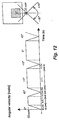
- the oscillation frequency is 0.2 cycle per second and the maximal angular velocity is about 0.62 rad per second or 35.6 degrees per second.
- a cartridge oscillation according to the diagram of Fig. 12 is used for instance during the sample hybridization step described hereinafter.
- the variation of the angle of oscillation with time has a similar shape as in Fig. 12, but the oscillation frequency is e.g. of 0.4 cycle per second.
- the function angle vs. time differs from the one shown by Fig. 12 and has approximately a sinusoidal shape in order that the movement parameters (location, velocity, acceleration) vary substantially smoothly.
- a method for processing a nucleic acid sample contained in a liquid can be carried out with the means described in this example and comprises the following steps:
- a method of the type just described is carried out simultaneously on a plurality of cartridges by means of a system adapted for that purpose and comprising a cartridge holder 36 and the means for oscillating it shown in Figures 6 to 11.
- a typical use of a cartridge according to the invention is for carrying out process steps of a so called post PCR processing of a nucleic acid sample which has been amplified by means of a PCR method or the like.
- Such post PCR processing carried out using cartridge 12 includes in general terms the following steps:
- a post PCR processing of an amplified nucleic acid sample using the devices described above comprises e.g. the following steps:
- a liquid containing this sample is introduced into cartridge 12 through an inlet thereof and by means of the pipetting needle of an automatic pipetting unit as shown by Fig. 1.
- a hybridization step by means of heat transfer the temperature of the cartridge is maintained at a predetermined level. Over the whole duration of this step, which usually takes between 30 and 60 minutes, but which can take up to 8 hours (e.g. for a gene expression), a relative movement of the sample containing liquid with respect to the active surface of the chip shaped carrier and thereby a flow of that liquid over that surface is effected by the means described above.
- this step it is important to note that the chamber and the channel within the cartridge are so configured that a uniform distribution of the liquid over the active surface of the chip shaped carrier is achieved.
- a first washing step the interior of cartridge 12 is rinsed with a washing buffer which flows into the cartridge through an inlet thereof and leaves it through an outlet thereof. This step is repeated up to ten times.
- This step serves for stabilizing the processing of the sample containing liquid contained in the cartridge. During this step which takes about 15 minutes, the liquid is kept at a different temperature level than during the hybridization step and is moved with respect to the active surface of the chip shaped carrier in the same way as during the hybridization step.
- a fluorescent solution is added to the sample containing liquid contained in the cartridge in order that individual fluorescing molecules can get attached to DNA fragments.
- the cartridge is kept again at a higher temperature level.
- step 6 the sample is bound to the active surface 15 of chip shaped carrier 14, this surface is flooded with a sample-free buffer, and the cartridge containing the sample containing liquid is transferred by suitable transport means which include a gripper to a detection unit, where the active surface of chip shaped carrier is scanned with a laser beam and fluorescent light emerging from said active surface in response to that excitation is measured by means of suitable instrument.
- suitable transport means which include a gripper to a detection unit, where the active surface of chip shaped carrier is scanned with a laser beam and fluorescent light emerging from said active surface in response to that excitation is measured by means of suitable instrument.
- the cartridge has an opening through which the chip shaped carrier and the active surface thereof are accessible to opto-electronic examination.
Abstract
Description
- The present invention relates to a system for processing a nucleic acid sample contained in a liquid.
- The invention further relates to a cartridge for processing a nucleic acid sample contained in a liquid.
- The invention relates in particular to a cartridge for processing a nucleic acid sample contained in a liquid introduced into the cartridge which contains a chip shaped carrier having a biochemically active surface which is adapted to be read by an opto-electronic reading device.
- Within the context of the instant invention a chip shaped carrier is a substrate, in particular a glass chip of e.g. squared shape having a thickness of e.g. 0.7 or 1.0 millimeter and a so called active surface, which is a surface coated with an array of different snippets of DNA or other molecular probes, e.g. DNA oligonucleotide probes, located at known positions on that surface. Those probes serve for detecting DNA fragments with a complementary DNA sequence.
- Within the context of the instant invention and in a preferred embodiment, the above- mentioned cartridge is in particular a cartridge made of a plastic material, which cartridge is used as a packaging device for packaging such a chip shaped carrier usually called DNA chip. More preferably, the cartridge is designed as a one-way cartridge.
- DNA chips contained in such cartridges have a wide range of applications. For example, they may be used for understanding the structure-activity relationship between different biological materials or determining the DNA-sequence of an unknown biological material. For instance, the DNA-sequence of such unknown material may be determined by, for example, a process known as sequencing by hybridization. In one method of sequencing by hybridization, sequences of diverse materials are formed at known locations on a surface of a chip, and a solution containing one or more targets to be sequenced is applied to that surface. The targets will bind or hybridize with only complementary sequences on the substrate. The locations at which hybridization occurs are detected with appropriate detection systems by labeling the targets with a fluorescent dye, radioactive isotope, enzyme, or other marker. Information about target sequences can be extracted from the data obtained by such detection systems.
- By combining various available technologies, such as photolithography and fabrication techniques, substantial progress has been made in the fabrication and placement of diverse materials on chips of the above mentioned kind. For example, thousands of different sequences may be fabricated on a single substrate of about 1.28 square centimeter in only a small fraction of the time required by conventional methods. Such improvements make these substrates practical for use in various applications, such as biomedical research, clinical diagnostics, and other industrial markets, as well as the emerging field of genomics, which focuses on determining the relationship between genetic sequences and human physiology.
- For efficient use of a chip shaped carrier of the above described type it is necessary that the sample solution containing one or more targets to be sequenced effectively contacts the active surface of the chip shaped carrier. Moreover, in view of the relatively large number of sample solutions to be processed, this effective contact should be achieved with high reproducibility and at low cost.
- Known prior art attempts to attain these aims require means for pumping a liquid containing a nucleic acid sample into and out a chamber of a cartridge in order to obtain the desired effective contact between the liquid containing the sample and the active surface of the chip shaped carrier. This approach is too expensive, cumbersome and requires too much working space, and can therefore not satisfy present day requirements on this kind of apparatuses.
- European patent application EP-A-0695941 describes a method and an apparatus for evaluating probe chips. This method includes the steps of
- (a) introducing a liquid sample into a chamber of a cartridge which contains a chip shaped carrier, an active surface of which carries an array of oligonucleotides, said chamber having a narrow interior and including a channel comprised between two inner surfaces of said chamber, and
- (b) positioning said cartridge in a cartridge holder. The apparatus described by EP-A-0695941 comprises a vortexer for rotating the cartridge e.g. at about 3000 cycles per minute. Operation of this vortexer is similar to that of a paint mixer.
- International Patent Application WO-A-99 38612 describes an apparatus having a cartridge which comprises a U-shaped flow chamber shown by Figures 11A and 11B of WO-A-99 38612. A first and a second arm of this flow chamber define each a sub-chamber. In use liquid is moved from one sub-chamber to the other by means of said valve and pumping means. The cartridge is stationarily arranged in the apparatus. The apparatus described by WO-A-99 38612 is for performing a separation of bioparticles on a bioelectronic chip by dielectrophoresis. This apparatus comprises suitable tubings and valves for supplying liquids to the flow chamber and for removing liquids therefrom by means of pumping means.
- U.S. Patent Specification No. 5,133,937 describes an analysis system for analyzing a biological fluid. This system comprises a replaceable cartridge assembly which contains a reaction chamber structure with an immobilized enzyme in the reaction chamber. The latter enzyme being capable of converting the constituent of interest to a constituent detectable by a measuring system.
- A main aim of the instant invention is therefore to provide a cartridge which makes it possible to provide effective contact of a solution processed in the cartridge of the above mentioned kind with the active surface of the chip shaped carrier and this with a high reproducibility and at low cost.
- According to the invention the above aim is achieved with a cartridge according to claim 1. Features of preferred embodiments are defined by the dependent claims.
- The main advantages of a cartridge according to the invention are that it makes possible to achieve the above mentioned, desirable effective contact between the sample solution and the active surface of the chip shaped carrier with high reproducibility and with simple means which in turn makes possible to achieve all this at low cost. This latter advantage becomes very important when a plurality of cartridges each containing a liquid containing a sample have to be simultaneously processed.
- Preferred embodiments of the invention are described hereinafter more in detail with reference to the accompanying drawings, wherein
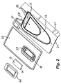
- Fig. 1 shows a schematic representation of a
cartridge 12 when it is being filled with a liquid containing a nucleic acid sample, - Fig. 2 shows an perspective exploded view of components of
cartridge 12 showing in particular the interior ofchamber 11 andchannel 13 formed in achannel plate 21 which is part ofcartridge 12, - Fig. 3 shows an perspective exploded view of components of
cartridge 12 seen from a point of view opposite to the one of Fig. 2 and showing in particular the inner surface of achip plate 22 which is part ofcartridge 12 and anactive surface 15 of achip carrier plate 14, - Fig. 4 shows a top view of the
channel plate 21 ofcartridge 12 and ofchannel 13 thereof, - Fig. 5 shows a cross-sectional view of the
channel plate 21 ofcartridge 12 and ofchannel 13 thereof, - Fig. 6 shows
cartridge 12 andcartridge holder 16 in a firstangular position 26, - Fig. 7 shows different angular positions of
cartridge 12, - Fig. 8 shows a system for handling a plurality of
cartridges 12 simultaneously, - Fig. 9 shows a transport head which has a
gripper 66 at the moment it positions acartridge 12 into a cartridge holder, - Fig. 10 shows a
cartridge 12 in a firstangular position 26, - Fig. 11 shows a
cartridge 12 in anangular position 29 which is the same as the one shown in Fig. 1, and - Fig. 12 shows a diagram of the variation of the angular velocity ω = dθ/dt with time for oscillation movement of
cartridge 12. - As schematically represented in Fig. 1, a
cartridge 12 according to the invention comprises achamber 11 which includes acurved channel 13. Cartridge 12 contains a chip shapedcarrier 14 having anactive surface 15 which carries an array of oligonucleotides and which faces aninner surface 24 of achannel plate 21, a part ofcartridge 12 described hereinafter with reference to Fig. 2. Chip shapedcarrier 14 is located in a central zone ofchannel 13. A portion of saidchannel 13 lies betweenactive surface 15 of chip shapedcarrier 14 and theinner surface 24 of achannel plate 21. In Fig. 1 line Z-Z is a vertical straight line. - Fig. 1 shows
cartridge holder 16 andcartridge 12 in aposition 29 at which a mid-axis S-S ofcartridge 12 lies in a horizontal plane and is thus perpendicular to line Z-Z. - Fig. 1 shows just one possible cartridge position which is suitable to introduce liquid into the cartridge or to remove liquid from the cartridge. Another possible and even more preferable cartridge position for this purpose is one where the mid-axis S-S of the cartridge forms an angle greater than 90 degrees with a horizontal plane, e.g. an angle of 110 degrees. Such a position is more advantageous for removing liquid from the channel of the cartridge, because its lower arm becomes more inclined.
- With
cartridge 12 in the position shown in Fig. 1, a predetermined volume of a liquid containing a nucleic acid sample is introduced intochamber 11 through anopening 35 ofcartridge 12 by means of apipetting needle 17 which is part of anautomatic pipetting unit 67 which is only partially represented in Fig. 1.Opening 35 is used as inlet and outlet ofcartridge 12. The level reached by the sample containing liquid inchamber 11 is represented in Fig. 1 byhorizontal line segments 18. - An advantage of the cartridge design represented in the enclosed drawings and of the initial position chosen for introducing a liquid containing a sample into the cartridge is that when a liquid is introduced into the cartridge as described above, the liquid initially remains below the lower edge of the chip shaped
carrier 14. This makes possible to choose the point of time at which the binding reaction between the sample contained in the liquid and the active surface of the chip shaped carrier starts by choosing the point of time at which the oscillation movement of the cartridges is started. - As shown more in detail by the perspective views shown by Figures 2 and 3,
cartridge 12 comprises the following components: achannel plate 21 which comprises and substantially defines the shape ofchamber 11 and ofchannel 13, and achip plate 22 which is adapted to receive and hold chip shapedcarrier 14 within acavity 23 ofchip plate 22.Channel plate 21 andchip plate 22 are so configured and dimensioned that they are adapted to be assembled together to formcartridge 12. - Fig. 2 shows the following parts of cartridge 12:
- the
inner surface 24 ofchannel plate 21, the interior ofchamber 11 andchannel 11 formed inchannel plate 21, - opening 35 of
channel plate 21 which is used as an inlet and outlet ofcartridge 12, theouter surface 33 ofchip plate 22, the interior ofcavity 23 ofchip plate 22 and theback side surface 19 of chip shapedcarrier 14 which lies on the opposite side of theactive surface 15 thereof. - Fig. 3 shows the following parts of
cartridge 12 not shown by Fig. 2: - the
inner surface 25 ofchip plate 22, theactive surface 15 of chip shapedcarrier 14, and theouter surface 34 ofchannel plate 21. -
Channel plate 21,chip plate 22 and other parts ofcartridge 12 are made preferably of plastic materials which are suitable manufacture by injection molding and also for carrying out the envisaged process steps for processing a sample containing liquid of the above mentioned kind. Such plastic materials should be chemically inert so that they cannot interfere with the processing of the samples contained in such liquids. Moreover the material chosen for the manufacture of components ofcartridge 12 should not be fluorescent, so that they cannot interfere with fluorescence measurements usually performed after processing e.g. a nucleic acid sample contained in a liquid.Channel plate 21 andchip plate 22 can but must not necessarily be transparent. - As shown by Figures 2 and 3, the upper part of
channel plate 21, whereopening 35 is located, comprises projections ortongues cartridge 12 and which are so configured and dimensioned that they are adapted to be grasped by a suitable gripper of a transport device in order to transport and insert acartridge 12 into acartridge holder 16 and to remove acartridge 12 from acartridge holder 16. - The process of manufacture of
cartridge 12 comprises positioning and fixing chip shapedcarrier 14 into a correspondingcavity 23 available inchip plate 22 e.g. by means of a sealingframe 41 and alocking frame 42 and by assembling togetherchannel plate 21 and chip plate withcarrier 14 attached to it in order to form acartridge 12 ready for use, wherein theactive surface 15 of carrier is at the above mentioned position with respect tochannel 13. The just mentioned assembling ofchannel plate 21 andchip plate 22forms chamber 11 andchannel 13 withincartridge 12. - The means for positioning and fixing chip shaped
carrier 14 intocavity 23 available inchip plate 22 are preferably those described in co-pending European patent application No. 00810501.7 published us EP 1161984 A1 and entitled "Device for packaging a chip shaped carrier and process for assembling a plurality of such carriers" filed on June 8, 2000 by the applicant of this application. - As shown more in detail by Figures 4 and 5,
curved channel 13 has a variable width and a variable depth along its length. As shown by Fig. 4, thewidth 37 ,respectively 38, of the end segments ofchannel 13 is smaller than thewidth 39 of the central part of this channel, and the width ofchannel 13 continuously increases over a portion ofchannel 13 and reaches a maximum value at the center thereof. As shown by Fig. 5, the depth ofchannel 13 has a minimum value D1 over the central part thereof, whereas in the end segments of channel 13 (i.e. outside the central part thereof) its depth D2 continuously increases with increasing distance from the center ofchannel 13 and reaches a maximum value at the end segments ofchannel 13. - In a preferred embodiment of the invention the variation of the width and the depth of
channel 13 along its length is so chosen and dimensioned that the cross-section ofchannel 13 remains fairly or at least approximately constant over its entire length or at least over a substantial part of its length. The relatively small value of the height (depth) ofchannel 13 yields a low Reynolds number and makes therefore possible to achieve a laminar flow of liquid withinchannel 13 whencartridge 12 is oscillated back and forth between two angular positions as described hereinafter. The advantageous effect of such a laminar flow is a very effective and reproducible contact between the nucleic acid sample contained in the liquid and theactive surface 15 of chip shapedcarrier 14. - An additional advantage which results from the combined choice of a
channel 13 having a curved shape and having a substantially constant cross-section over its length is that it makes possible to make acompact cartridge 12 of relatively small dimensions, and this in turn makes it possible to accommodate a plurality of such cartridges in a compactly built apparatus. - As can be appreciated in particular from Figures 4 and 5, but also from Figures 2 and 3,
chamber 11 has a narrow interior and includes acurved channel 13 which is formed withinchamber 11.Chamber 11 andchannel 13 are cavities comprised betweeninner surface 24 ofchannel plate 21 andinner surface 25 ofchip plate 22. These inner surfaces are shown by Fig. 2 respectively Fig. 3 and are substantially opposite to each other. One of these inner surfaces is aninner surface 24 ofchannel plate 21 and the other is aninner surface 25 ofchip plate 22. - In order to perform the method described hereinafter for processing a nucleic acid sample contained in a liquid,
cartridge 12 is inserted and thereby positioned into acartridge holder 16 which is represented schematically in Figures 1, 6 and 7. -
Cartridge 12 andcartridge holder 16 are so configured that whencartridge 12 is positioned intocartridge holder 16 theactive surface 15 of chip shapedcarrier 14 preferably lies in a substantially vertical plane. However, theactive surface 15 does not need to be vertical, it may also be inclined or even horizontal, even if these variants are expected to perform less well. -
Cartridge 12 is used e.g. in a system which comprises acartridge 12 and acartridge holder 16 having the above described features and comprises in addition means for oscillatingcartridge holder 16 and therebycartridge 12 about an axis of rotation which is substantially perpendicular to the above mentioned vertical plane. - The means for oscillating
cartridge holder 16 are in particular adapted for movingcartridge holder 16 and therebycartridge 12 back and forth between a firstangular position 26 and a secondangular position 28 shown in Fig. 7. During these oscillations theactive surface 15 of chip shapedcarrier 14 lies in a substantially vertical plane. Fig. 6 also showscartridge 12 in firstangular position 26. - Fig. 7 shows different angular positions of
cartridge 12. As can be appreciated from Fig. 7,angular positions 26 respectively 28 lie on opposite sides of an intermediateangular position 27 at which theactive surface 15 of chip shapedcarrier 14 is at the lowest part of its motion path during oscillation ofcartridge holder 16 and therebycartridge 12 back and forth between first and secondangular positions 26 respectively 28. Whencartridge 12 is oscillated in this way gravity force acting on the liquid contained inchannel 13 ofcartridge 12 maintainslevel 18 of the liquid in a horizontal plane and causes a relative motion of the sample containing liquid inchannel 13 with respect to theactive surface 15 of chip shapedcarrier 14. This relative motion provides a very effective contact of that liquid containing the sample with theactive surface 15 of chip shapedcarrier 14. - In Figures 6 and 7 line Z-Z is a vertical straight line.
- At the intermediate angular position of
cartridge 12 its mid-axis S-S is in a vertical position and is thus parallel to line Z-Z. At the firstangular position 26 ofcartridge 12 its mid-axis S-S forms a positive angle with a vertical line parallel to line Z-Z. At the secondangular position 28 ofcartridge 12 its mid-axis S-S forms a negative angle with a vertical line parallel to line Z-Z. - In a preferred embodiment, first
angular position 26 is located at an angle of about plus forty degrees with respect to the intermediateangular position 27, and secondangular position 28 is located at an angle of about minus forty degrees with respect to the intermediateangular position 27. An angle smaller than plus/minus 40 degrees is even more preferable in order to reduce the size of the cartridge. - The means for oscillating
cartridge holder 16 are also adapted for bringingcartridge holder 16 and therebycartridge 12 to the angular position shown in Fig. 1 which is at an angle of ninety degrees with respect to the intermediateangular position 27 shown in Fig. 7. As mentioned above an angle larger than 90 degrees, e.g. 110 degrees, is also suitable and even more preferable. - The means for oscillating a
cartridge holder 16 holding asingle cartridge 12 are in principle very similar to those described hereinafter with reference to Fig. 8 for oscillating acartridge holder 36 adapted for holding a plurality ofcartridges 12. - Fig. 8 shows a side view of a preferred embodiment of a system wherein
cartridge 12 is used. This embodiment comprises acartridge holder 36 having a plurality of compactly arranged chambers each of which is adapted to receive and hold acartridge 12, and a means for oscillating cartridge holder 56. This system is thus adapted to receive and hold a plurality ofcartridges 12 and to oscillate them simultaneously in a similar way as described above for the case of asingle cartridge holder 16. -
Cartridges 12 andcartridge holder 36 are so configured that whencartridges 12 are positioned intocartridge holder 36 theactive surface 15 of each chip shapedcarrier 14 preferably lies in a substantially vertical plane. However, theactive surface 15 does not need to be vertical, it may also be inclined or even horizontal, even if these variants are expected to perform less well. - Fig. 9 shows a
transport head 65 which has agripper 66 at the moment it positions acartridge 12 into acartridge holder 36 shown in Fig. 8. Also represented in Fig. 9 are means for oscillatingcartridge holder 36 and therebycartridges 12 positioned into that holder. These means include e.g. a step motor or aDC motor 61, drive means 62 and coupling means 63 located betweenmotor 61 and drive means 62. Drive means 62 and coupling means 63 can include e.g. a serrated belt, a gearing, a friction drive or a steel band. - Fig. 10 shows a
cartridge 12 in a firstangular position 26. - Fig. 11 shows a
cartridge 12 in anangular position 29 which is the same as the one shown in Fig. 1. Also represented in Fig. 11 is apart 67 of a pipetting unit. Thispart 67 is moved by means oftransport head 65, which as mentioned above also carries and movesgripper 66.Part 67 of the automatic pipetting unit comprises pipettingneedle 17 shown also in Fig. 1. - Fig. 12 shows as an example a diagram of the variation of the angular velocity ω = dθ/dt with time which is achievable with the above described means for oscillating
cartridge 12 for the case where the angle of oscillation varies between plus 40 degrees and minus 40 degrees. With the values shown in this diagram the oscillation frequency is 0.2 cycle per second and the maximal angular velocity is about 0.62 rad per second or 35.6 degrees per second. A cartridge oscillation according to the diagram of Fig. 12 is used for instance during the sample hybridization step described hereinafter. For the sample rinse step described hereinafter the variation of the angle of oscillation with time has a similar shape as in Fig. 12, but the oscillation frequency is e.g. of 0.4 cycle per second. - In a preferred embodiment, the function angle vs. time differs from the one shown by Fig. 12 and has approximately a sinusoidal shape in order that the movement parameters (location, velocity, acceleration) vary substantially smoothly.
- A method for processing a nucleic acid sample contained in a liquid can be carried out with the means described in this example and comprises the following steps:
- (a) introducing a liquid containing a nucleic acid sample into
chamber 11 ofcartridge 12 and thereby intochannel 13 formed within that chamber, - (b)
positioning cartridge 12 intocartridge holder 16 in such a way thatactive surface 15 of chip shapedcarrier 14 lies in a substantially vertical plane, this positioning ofcartridge 12 incartridge holder 16 being effected before or after introduction of the liquid containing said sample intochamber 11, - (c) oscillating
cartridge holder 16 and therebycartridge 12 about an axis of rotation which is substantially perpendicular to a vertical plane, thereby moving saidcartridge 12 back and forth between firstangular position 26 and secondangular position 28 which lie on opposite sides of an intermediateangular position 27 at whichactive surface 15 of chip shapedcarrier 14 is substantially at the lowest part of its motion path caused by the above mentioned movement ofcartridge 12 in order to cause a relative motion of the liquid contained inchannel 13 with respect toactive surface 15 of said chip shapedcarrier 14. - According to a preferred embodiment, a method of the type just described is carried out simultaneously on a plurality of cartridges by means of a system adapted for that purpose and comprising a
cartridge holder 36 and the means for oscillating it shown in Figures 6 to 11. - A typical use of a cartridge according to the invention is for carrying out process steps of a so called post PCR processing of a nucleic acid sample which has been amplified by means of a PCR method or the like.
- Such post PCR processing carried out using
cartridge 12 includes in general terms the following steps: - introducing liquid into
chamber 11 and intochannel 13 ofcartridge 12 at some points of time and withdrawing liquid fromchamber 11 andchannel 13 ofcartridge 12 at other points of time, repeating this steps several times, and - heating and
cooling cartridge 12 during predetermined time intervals according to predetermined temperature profiles, e.g. in a temperature range between zero and seventy degrees Celsius. The liquid containing a nucleic acid sample is one of the liquids introduced into and withdrawn fromcartridge 12. Another type of liquid handled in this way as part of the method is e.g. buffer liquid used for rinsingchamber 11 andchannel 13 during rinsing steps mentioned hereinafter. - More in detail a post PCR processing of an amplified nucleic acid sample using the devices described above comprises e.g. the following steps:
- A liquid containing this sample is introduced into
cartridge 12 through an inlet thereof and by means of the pipetting needle of an automatic pipetting unit as shown by Fig. 1. - During a hybridization step by means of heat transfer the temperature of the cartridge is maintained at a predetermined level. Over the whole duration of this step, which usually takes between 30 and 60 minutes, but which can take up to 8 hours (e.g. for a gene expression), a relative movement of the sample containing liquid with respect to the active surface of the chip shaped carrier and thereby a flow of that liquid over that surface is effected by the means described above. In connection with this step it is important to note that the chamber and the channel within the cartridge are so configured that a uniform distribution of the liquid over the active surface of the chip shaped carrier is achieved.
- In a first washing step (rinse) the interior of
cartridge 12 is rinsed with a washing buffer which flows into the cartridge through an inlet thereof and leaves it through an outlet thereof. This step is repeated up to ten times. - This step serves for stabilizing the processing of the sample containing liquid contained in the cartridge. During this step which takes about 15 minutes, the liquid is kept at a different temperature level than during the hybridization step and is moved with respect to the active surface of the chip shaped carrier in the same way as during the hybridization step.
- In this step a fluorescent solution is added to the sample containing liquid contained in the cartridge in order that individual fluorescing molecules can get attached to DNA fragments. During this step the cartridge is kept again at a higher temperature level.
- In this step remaining free fluorescing molecules are washed out of the cartridge by means injecting a washing buffer through an inlet of the cartridge at a suitable first position thereof and changing the position cartridge to a second position at which liquid carrying those free fluorescing molecules is withdrawn from the cartridge through an outlet thereof. This step is repeated up to ten times.
- After step 6) the sample is bound to the
active surface 15 of chip shapedcarrier 14, this surface is flooded with a sample-free buffer, and the cartridge containing the sample containing liquid is transferred by suitable transport means which include a gripper to a detection unit, where the active surface of chip shaped carrier is scanned with a laser beam and fluorescent light emerging from said active surface in response to that excitation is measured by means of suitable instrument. In order that this detection can be performed the cartridge has an opening through which the chip shaped carrier and the active surface thereof are accessible to opto-electronic examination. -
- 11
- chamber
- 12
- cartridge
- 13
- channel
- 14
- chip shaped carrier of an array of oligonucleotides
- 15
- active surface of
carrier 14 - 16
- cartridge holder
- 17
- pipetting needle
- 18
- level of liquid contained in
cartridge 12 - 19
- back side surface of chip shaped
carrier 14 - 21
- channel plate
- 22
- chip plate
- 23
- cavity of chip plate
- 24
- inner surface of channel plate
- 25
- inner surface of chip plate
- 26
- first angular position
- 27
- intermediate angular position
- 28
- second angular position
- 29
- angular position of
cartridge 12 for effecting a pipetting operation - 31
- tongue
- 32
- tongue
- 33
- outer surface of
chip plate 22 - 34
- outer surface of
channel plate 21 - 35
- opening (inlet/outlet)
- 36
- cartridge holder
- 37
- width of end segment of
channel 13 - 38
- width of end segment of
channel 13 - 39
- width of central part of
channel 13 - 41
- sealing frame
- 42
- locking frame
- 61
- motor
- 62
- drive means
- 63
- coupling means
- 65
- transport head
- 66
- gripper
- 67
- pipetting unit
- S-S
- mid-axis of
cartridge 12 - Z-Z
- a vertical straight line
- Modifications and alternative embodiments of the cartridge according to the invention will be apparent to those skilled in the art in view of the foregoing description. Accordingly, this description is to be construed as illustrative only and is for the purpose of teaching those skilled in the art the best mode of carrying out the invention. Details of the cartridge described may be varied without departing from the spirit of the invention and the exclusive use of all modifications which come within the scope of the appended claims is reserved.
Claims (3)
- A cartridge for processing a nucleic acid sample contained in a liquid, said cartridge including
a chip shaped carrier (14) having an active surface (15) which carries an array of oligonucleotides, said active surface (15) facing an inner surface (24) of a part (21) of said cartridge (12),
said cartridge being characterized in that it further comprises
a chamber (11) having a narrow interior and including a curved channel (13), a portion of said channel (13) lying between said active surface (15) and said inner surface (24) . - A cartridge according to claim 1, wherein said active surface (15) of chip shaped carrier (14) is adjacent to a central portion of said channel (13).
- A cartridge according to claim 1, wherein said cartridge is a disposable component and is made of a plastic material.
Priority Applications (1)
| Application Number | Priority Date | Filing Date | Title |
|---|---|---|---|
| EP05022568.9A EP1623762A3 (en) | 2000-12-28 | 2000-12-28 | Cartridge for processing a nucleic acid sample |
Applications Claiming Priority (2)
| Application Number | Priority Date | Filing Date | Title |
|---|---|---|---|
| EP05022568.9A EP1623762A3 (en) | 2000-12-28 | 2000-12-28 | Cartridge for processing a nucleic acid sample |
| EP00811253A EP1224976B1 (en) | 2000-12-28 | 2000-12-28 | Method, system and cartridge for processing a nucleic acid sample by oscillating the cartridge |
Related Parent Applications (1)
| Application Number | Title | Priority Date | Filing Date |
|---|---|---|---|
| EP00811253A Division EP1224976B1 (en) | 2000-12-28 | 2000-12-28 | Method, system and cartridge for processing a nucleic acid sample by oscillating the cartridge |
Publications (2)
| Publication Number | Publication Date |
|---|---|
| EP1623762A2 true EP1623762A2 (en) | 2006-02-08 |
| EP1623762A3 EP1623762A3 (en) | 2014-05-21 |
Family
ID=8175115
Family Applications (2)
| Application Number | Title | Priority Date | Filing Date |
|---|---|---|---|
| EP05022568.9A Withdrawn EP1623762A3 (en) | 2000-12-28 | 2000-12-28 | Cartridge for processing a nucleic acid sample |
| EP00811253A Expired - Lifetime EP1224976B1 (en) | 2000-12-28 | 2000-12-28 | Method, system and cartridge for processing a nucleic acid sample by oscillating the cartridge |
Family Applications After (1)
| Application Number | Title | Priority Date | Filing Date |
|---|---|---|---|
| EP00811253A Expired - Lifetime EP1224976B1 (en) | 2000-12-28 | 2000-12-28 | Method, system and cartridge for processing a nucleic acid sample by oscillating the cartridge |
Country Status (7)
| Country | Link |
|---|---|
| US (2) | US6921639B2 (en) |
| EP (2) | EP1623762A3 (en) |
| JP (2) | JP3970023B2 (en) |
| AT (1) | ATE337093T1 (en) |
| CA (1) | CA2364146C (en) |
| DE (1) | DE60030306T2 (en) |
| ES (1) | ES2269093T3 (en) |
Families Citing this family (20)
| Publication number | Priority date | Publication date | Assignee | Title |
|---|---|---|---|---|
| DE60030306T2 (en) | 2000-12-28 | 2007-08-30 | Roche Diagnostics Gmbh | Method, system and cartridge for processing a nucleic acid sample by oscillation of the cartridge |
| EP1419821A1 (en) * | 2002-11-14 | 2004-05-19 | F. Hoffmann-La Roche Ag | Method, system and reaction vessel for processing a biological sample contained in a liquid |
| EP1419820A1 (en) * | 2002-11-14 | 2004-05-19 | F. Hoffmann-La Roche Ag | Method, system and reaction vessel for processing a biological sample contained in a liquid |
| ATE377194T1 (en) | 2004-07-02 | 2007-11-15 | Hoffmann La Roche | DEVICE FOR RELIABLE ANALYSIS |
| WO2007006315A2 (en) * | 2005-07-07 | 2007-01-18 | Inverness Medical Switzerland Gmbh | A method of performing a test, a support instrument and a microliquid system comprising such support instrument |
| ES2688281T3 (en) | 2006-07-28 | 2018-10-31 | Diagnostics For The Real World, Ltd | Device, system and method to process a sample |
| EP2101917A1 (en) | 2007-01-10 | 2009-09-23 | Scandinavian Micro Biodevices A/S | A microfluidic device and a microfluidic system and a method of performing a test |
| WO2008139415A1 (en) * | 2007-05-14 | 2008-11-20 | Koninklijke Philips Electronics N.V. | Microfluidic device and method of operating a microfluidic device |
| US9707556B2 (en) | 2007-08-17 | 2017-07-18 | Diagnostics For The Real World, Ltd. | Device, system and method for processing a sample |
| JPWO2010001636A1 (en) * | 2008-07-01 | 2011-12-15 | 日本碍子株式会社 | DNA array |
| JP5867668B2 (en) | 2010-12-01 | 2016-02-24 | セイコーエプソン株式会社 | Thermal cycling apparatus and thermal cycling method |
| JP5896100B2 (en) * | 2011-03-01 | 2016-03-30 | セイコーエプソン株式会社 | Heat cycle equipment |
| JP5971463B2 (en) | 2012-03-30 | 2016-08-17 | セイコーエプソン株式会社 | Thermal cycle device and control method for thermal cycle device |
| JP2013208066A (en) | 2012-03-30 | 2013-10-10 | Seiko Epson Corp | Thermal cycler and control method of thermal cycler |
| JP2013252091A (en) * | 2012-06-06 | 2013-12-19 | Seiko Epson Corp | Thermal cycler |
| JP5967361B2 (en) | 2012-06-06 | 2016-08-10 | セイコーエプソン株式会社 | Heat cycle equipment |
| JP2015154722A (en) | 2014-02-20 | 2015-08-27 | セイコーエプソン株式会社 | Nucleic acid amplification reaction vessel and nucleic acid amplification reaction device |
| WO2015187849A2 (en) | 2014-06-04 | 2015-12-10 | Lucigen Corporation | Sample collection and analysis devices |
| CN109794308B (en) * | 2017-11-17 | 2021-05-04 | 长春长光华大智造测序设备有限公司 | Biochip bears frame |
| CN113559753B (en) * | 2021-09-23 | 2021-12-03 | 启锰生物科技(江苏)有限公司 | Detection subassembly that adjuvant vaccine used |
Citations (4)
| Publication number | Priority date | Publication date | Assignee | Title |
|---|---|---|---|---|
| WO1997039151A1 (en) * | 1996-04-17 | 1997-10-23 | Affymetrix, Inc. | Photolabile polymer array synthesis methods |
| US5922604A (en) * | 1997-06-05 | 1999-07-13 | Gene Tec Corporation | Thin reaction chambers for containing and handling liquid microvolumes |
| WO1999038612A1 (en) * | 1998-01-30 | 1999-08-05 | Nanogen, Inc. | Channel-less separation of bioparticles on a bioelectronic chip by dielectrophoresis |
| EP0969083A1 (en) * | 1997-08-29 | 2000-01-05 | Olympus Optical Co., Ltd. | Dna capillary |
Family Cites Families (11)
| Publication number | Priority date | Publication date | Assignee | Title |
|---|---|---|---|---|
| US5133937A (en) * | 1989-06-01 | 1992-07-28 | Iniziative Marittime, 1991 S.R.L. | Analysis system having a removable reaction cartridge and temperature control |
| DE69527585T2 (en) * | 1994-06-08 | 2003-04-03 | Affymetrix Inc | Method and device for packaging chips |
| CA2296341A1 (en) | 1997-07-18 | 1999-01-28 | C.A. Arnold & Associates, Inc. | Pulverizing materials into small particles |
| US5961930A (en) * | 1997-10-15 | 1999-10-05 | Eastman Kodak Company | Integrated micro-ceramic chemical plant with insertable reaction chambers and micro-filters |
| US6087102A (en) * | 1998-01-07 | 2000-07-11 | Clontech Laboratories, Inc. | Polymeric arrays and methods for their use in binding assays |
| CA2319587C (en) | 1998-02-11 | 2004-09-21 | University Of Houston | Method and apparatus for chemical and biochemical reactions using photo-generated reagents |
| FR2806165B1 (en) * | 2000-03-09 | 2003-01-17 | Genomic Sa | AUTOMATON FOR BIOLOGICAL ANALYSIS |
| JP3871846B2 (en) * | 2000-03-10 | 2007-01-24 | 日立ソフトウエアエンジニアリング株式会社 | Hybridization reaction detection method and detection apparatus |
| EP1397679B1 (en) | 2000-11-27 | 2010-01-20 | Intelligent Medical Devices LLC | Clinically intelligent diagnostic devices and methods |
| DE60030306T2 (en) * | 2000-12-28 | 2007-08-30 | Roche Diagnostics Gmbh | Method, system and cartridge for processing a nucleic acid sample by oscillation of the cartridge |
| EP1226863B1 (en) * | 2000-12-28 | 2004-11-03 | F.Hoffmann-La Roche Ag | Method for processing a nucleic acid sample by swinging a segment of a cartridge wall, a system and a cartridge for performing such a method |
-
2000
- 2000-12-28 DE DE60030306T patent/DE60030306T2/en not_active Expired - Lifetime
- 2000-12-28 EP EP05022568.9A patent/EP1623762A3/en not_active Withdrawn
- 2000-12-28 ES ES00811253T patent/ES2269093T3/en not_active Expired - Lifetime
- 2000-12-28 EP EP00811253A patent/EP1224976B1/en not_active Expired - Lifetime
- 2000-12-28 AT AT00811253T patent/ATE337093T1/en active
-
2001
- 2001-11-30 CA CA2364146A patent/CA2364146C/en not_active Expired - Fee Related
- 2001-12-27 JP JP2001397708A patent/JP3970023B2/en not_active Expired - Fee Related
- 2001-12-27 US US10/033,424 patent/US6921639B2/en not_active Expired - Fee Related
-
2005
- 2005-04-04 US US11/099,107 patent/US7435575B2/en not_active Expired - Fee Related
-
2006
- 2006-09-11 JP JP2006245035A patent/JP4512573B2/en not_active Expired - Fee Related
Patent Citations (4)
| Publication number | Priority date | Publication date | Assignee | Title |
|---|---|---|---|---|
| WO1997039151A1 (en) * | 1996-04-17 | 1997-10-23 | Affymetrix, Inc. | Photolabile polymer array synthesis methods |
| US5922604A (en) * | 1997-06-05 | 1999-07-13 | Gene Tec Corporation | Thin reaction chambers for containing and handling liquid microvolumes |
| EP0969083A1 (en) * | 1997-08-29 | 2000-01-05 | Olympus Optical Co., Ltd. | Dna capillary |
| WO1999038612A1 (en) * | 1998-01-30 | 1999-08-05 | Nanogen, Inc. | Channel-less separation of bioparticles on a bioelectronic chip by dielectrophoresis |
Also Published As
| Publication number | Publication date |
|---|---|
| EP1224976B1 (en) | 2006-08-23 |
| JP2002257830A (en) | 2002-09-11 |
| DE60030306D1 (en) | 2006-10-05 |
| CA2364146A1 (en) | 2002-06-28 |
| US20020155475A1 (en) | 2002-10-24 |
| JP4512573B2 (en) | 2010-07-28 |
| JP3970023B2 (en) | 2007-09-05 |
| JP2007010684A (en) | 2007-01-18 |
| ATE337093T1 (en) | 2006-09-15 |
| EP1623762A3 (en) | 2014-05-21 |
| CA2364146C (en) | 2010-09-14 |
| US7435575B2 (en) | 2008-10-14 |
| DE60030306T2 (en) | 2007-08-30 |
| US20050170496A1 (en) | 2005-08-04 |
| EP1224976A1 (en) | 2002-07-24 |
| ES2269093T3 (en) | 2007-04-01 |
| US6921639B2 (en) | 2005-07-26 |
Similar Documents
| Publication | Publication Date | Title |
|---|---|---|
| US7435575B2 (en) | Method for processing a nucleic acid sample by oscillating a cartridge, a system and a cartridge for performing such a method | |
| EP1385006A2 (en) | System and cartridge for processing a biological sample | |
| EP1608952B1 (en) | Assay apparatus and method using microfluidic arrays | |
| US7326561B2 (en) | Flow-thru chip cartridge, chip holder, system and method thereof | |
| JP5236056B2 (en) | Reaction vessel and reaction control device | |
| JP4820756B2 (en) | Reaction vessel, reaction vessel liquid introduction device, liquid introduction reaction measuring device, and liquid introduction device | |
| EP1226863B1 (en) | Method for processing a nucleic acid sample by swinging a segment of a cartridge wall, a system and a cartridge for performing such a method | |
| JP4755588B2 (en) | Reaction vessel, reaction measuring device, and liquid rotation processing device | |
| JP4754746B2 (en) | Rod-shaped carrier and cylinder reaction vessel equipped with the same | |
| US20060078934A1 (en) | Method for acceleration and intensification of target-receptor binding and devices therefor | |
| JP2000346842A (en) | Method and device for production of probe array using micro particles | |
| JP4411661B2 (en) | Biological substance detection method | |
| JP4351028B2 (en) | Method, system and reaction vessel for processing a biological sample contained in a liquid | |
| JP4473007B2 (en) | Hybridization method | |
| EP1419821A1 (en) | Method, system and reaction vessel for processing a biological sample contained in a liquid | |
| JPWO2004104584A1 (en) | Biologically related substance inspection method, fluid transfer device and fluid transfer method therefor | |
| JP2002303627A (en) | Dna microarray preparing method and dna microarray container |
Legal Events
| Date | Code | Title | Description |
|---|---|---|---|
| PUAI | Public reference made under article 153(3) epc to a published international application that has entered the european phase |
Free format text: ORIGINAL CODE: 0009012 |
|
| 17P | Request for examination filed |
Effective date: 20051017 |
|
| AC | Divisional application: reference to earlier application |
Ref document number: 1224976 Country of ref document: EP Kind code of ref document: P |
|
| AK | Designated contracting states |
Kind code of ref document: A2 Designated state(s): AT BE CH CY DE DK ES FI FR GB GR IE IT LI LU MC NL PT SE TR |
|
| PUAL | Search report despatched |
Free format text: ORIGINAL CODE: 0009013 |
|
| AK | Designated contracting states |
Kind code of ref document: A3 Designated state(s): AT BE CH CY DE DK ES FI FR GB GR IE IT LI LU MC NL PT SE TR |
|
| RIC1 | Information provided on ipc code assigned before grant |
Ipc: G01N 35/00 20060101ALI20140417BHEP Ipc: B01L 3/00 20060101AFI20140417BHEP Ipc: B01L 9/00 20060101ALI20140417BHEP Ipc: B01F 11/00 20060101ALI20140417BHEP |
|
| 17Q | First examination report despatched |
Effective date: 20140602 |
|
| STAA | Information on the status of an ep patent application or granted ep patent |
Free format text: STATUS: THE APPLICATION IS DEEMED TO BE WITHDRAWN |
|
| 18D | Application deemed to be withdrawn |
Effective date: 20140701 |