EP1630902A2 - An electrical connector and a shield member for flat cables. - Google Patents
An electrical connector and a shield member for flat cables. Download PDFInfo
- Publication number
- EP1630902A2 EP1630902A2 EP05107462A EP05107462A EP1630902A2 EP 1630902 A2 EP1630902 A2 EP 1630902A2 EP 05107462 A EP05107462 A EP 05107462A EP 05107462 A EP05107462 A EP 05107462A EP 1630902 A2 EP1630902 A2 EP 1630902A2
- Authority
- EP
- European Patent Office
- Prior art keywords
- shield member
- circuit board
- shield
- electrical connector
- contacts
- Prior art date
- Legal status (The legal status is an assumption and is not a legal conclusion. Google has not performed a legal analysis and makes no representation as to the accuracy of the status listed.)
- Withdrawn
Links
Images


Classifications
-
- H—ELECTRICITY
- H01—ELECTRIC ELEMENTS
- H01R—ELECTRICALLY-CONDUCTIVE CONNECTIONS; STRUCTURAL ASSOCIATIONS OF A PLURALITY OF MUTUALLY-INSULATED ELECTRICAL CONNECTING ELEMENTS; COUPLING DEVICES; CURRENT COLLECTORS
- H01R13/00—Details of coupling devices of the kinds covered by groups H01R12/70 or H01R24/00 - H01R33/00
- H01R13/648—Protective earth or shield arrangements on coupling devices, e.g. anti-static shielding
-
- H—ELECTRICITY
- H01—ELECTRIC ELEMENTS
- H01R—ELECTRICALLY-CONDUCTIVE CONNECTIONS; STRUCTURAL ASSOCIATIONS OF A PLURALITY OF MUTUALLY-INSULATED ELECTRICAL CONNECTING ELEMENTS; COUPLING DEVICES; CURRENT COLLECTORS
- H01R12/00—Structural associations of a plurality of mutually-insulated electrical connecting elements, specially adapted for printed circuits, e.g. printed circuit boards [PCB], flat or ribbon cables, or like generally planar structures, e.g. terminal strips, terminal blocks; Coupling devices specially adapted for printed circuits, flat or ribbon cables, or like generally planar structures; Terminals specially adapted for contact with, or insertion into, printed circuits, flat or ribbon cables, or like generally planar structures
- H01R12/70—Coupling devices
- H01R12/77—Coupling devices for flexible printed circuits, flat or ribbon cables or like structures
- H01R12/771—Details
- H01R12/775—Ground or shield arrangements
-
- H—ELECTRICITY
- H01—ELECTRIC ELEMENTS
- H01R—ELECTRICALLY-CONDUCTIVE CONNECTIONS; STRUCTURAL ASSOCIATIONS OF A PLURALITY OF MUTUALLY-INSULATED ELECTRICAL CONNECTING ELEMENTS; COUPLING DEVICES; CURRENT COLLECTORS
- H01R12/00—Structural associations of a plurality of mutually-insulated electrical connecting elements, specially adapted for printed circuits, e.g. printed circuit boards [PCB], flat or ribbon cables, or like generally planar structures, e.g. terminal strips, terminal blocks; Coupling devices specially adapted for printed circuits, flat or ribbon cables, or like generally planar structures; Terminals specially adapted for contact with, or insertion into, printed circuits, flat or ribbon cables, or like generally planar structures
- H01R12/70—Coupling devices
- H01R12/82—Coupling devices connected with low or zero insertion force
- H01R12/85—Coupling devices connected with low or zero insertion force contact pressure producing means, contacts activated after insertion of printed circuits or like structures
- H01R12/88—Coupling devices connected with low or zero insertion force contact pressure producing means, contacts activated after insertion of printed circuits or like structures acting manually by rotating or pivoting connector housing parts
-
- H—ELECTRICITY
- H01—ELECTRIC ELEMENTS
- H01R—ELECTRICALLY-CONDUCTIVE CONNECTIONS; STRUCTURAL ASSOCIATIONS OF A PLURALITY OF MUTUALLY-INSULATED ELECTRICAL CONNECTING ELEMENTS; COUPLING DEVICES; CURRENT COLLECTORS
- H01R12/00—Structural associations of a plurality of mutually-insulated electrical connecting elements, specially adapted for printed circuits, e.g. printed circuit boards [PCB], flat or ribbon cables, or like generally planar structures, e.g. terminal strips, terminal blocks; Coupling devices specially adapted for printed circuits, flat or ribbon cables, or like generally planar structures; Terminals specially adapted for contact with, or insertion into, printed circuits, flat or ribbon cables, or like generally planar structures
- H01R12/70—Coupling devices
- H01R12/77—Coupling devices for flexible printed circuits, flat or ribbon cables or like structures
- H01R12/79—Coupling devices for flexible printed circuits, flat or ribbon cables or like structures connecting to rigid printed circuits or like structures
-
- H—ELECTRICITY
- H01—ELECTRIC ELEMENTS
- H01R—ELECTRICALLY-CONDUCTIVE CONNECTIONS; STRUCTURAL ASSOCIATIONS OF A PLURALITY OF MUTUALLY-INSULATED ELECTRICAL CONNECTING ELEMENTS; COUPLING DEVICES; CURRENT COLLECTORS
- H01R13/00—Details of coupling devices of the kinds covered by groups H01R12/70 or H01R24/00 - H01R33/00
- H01R13/648—Protective earth or shield arrangements on coupling devices, e.g. anti-static shielding
- H01R13/658—High frequency shielding arrangements, e.g. against EMI [Electro-Magnetic Interference] or EMP [Electro-Magnetic Pulse]
- H01R13/6581—Shield structure
- H01R13/6582—Shield structure with resilient means for engaging mating connector
- H01R13/6583—Shield structure with resilient means for engaging mating connector with separate conductive resilient members between mating shield members
Definitions
- the present invention relates to an electrical connector for flat cables, which is utilized in electronic devices such as cellular telephones.
- the present invention also relates to a shield member, which is employed in the electrical connector for flat cables.
- the present invention relates to a shielded (electromagnetic shield) electrical connector for flat cables and a shield member employed therefor.
- FIG. 2000-231971 discloses a connector, which is utilized to connect FPC's (Flexible Printed Circuits).
- FPC Flexible Printed Circuits
- This connector comprises a pair of connectors, one on the side of a circuit board, and one on the side of the cable (FPC) .
- a shell shield member
- a grounding conductor of the FPC is connected to the shell of the cable side connector.
- the shells are mounted on the exteriors of housings having predetermined shapes, and are thereby built into the connector. Accordingly, the shielding properties are stable.
- a connector is equipped with a openable/closable locking member, for fixing an FFC (Flexible Flat Cable) or an FPC
- the locking member temporarily protrudes toward the exterior of a housing during operation thereof. Therefore, a shielding structure such as that disclosed in the known FPC connector cannot be employed in a connector equipped with a locking member.
- problems such as spurious radiation (electromagnetic waves) being emitted from the connector itself, and external electromagnetic waves entering the electrical paths of the connector arise.
- the present invention has been developed in view of the foregoing circumstances. It is an object of the present invention to provide an electrical connector for flat cables and a shield member to be employed therefor, which have improved EMI (Electro Magnetic Interference) properties.
- EMI Electro Magnetic Interference
- an electrical connector for flat cables comprising:
- the shield member comprises: elastic mounting pieces formed as clips, to enable mounting of the shield member onto the insulative hosing in a removable manner; and tongue pieces, provided at a first end and a second end of the shield member; wherein: the tongue piece at the first end elastically contacts the shield of the flat cable and the tongue piece at the second end elastically contacts the grounding portion of the circuit board, when the shield member is mounted on the insulative housing.
- the shield member may be supported in a see-saw fashion, by the mounting pieces, which have pivot points between the first end and the second end.
- Protrusions that contact the circuit board to restrict movement of the shield member toward the circuit board may be provided on the mounting pieces.
- a shield member to be employed in an electrical connector for flat cables to cover the outer surfaces of an insulative housing of the electrical connector, which is mounted on a circuit board comprising: elastic mounting pieces formed as clips; a tongue piece at a first end of the shield member; and a tongue piece at a second end of the shield member; the tongue piece at the first end elastically contacting a shield of a flat cable and the tongue piece at the second end elastically contacting a grounding portion of the circuit board, when the shield member is mounted on the insulative housing.
- Protrusions that contact the circuit board to restrict movement of the shield member toward the circuit board may be provided on the mounting pieces.
- the electrical connector for flat cables of the present invention comprises the shield member, which is mounted on the insulative housing so as to substantially cover the outer surfaces thereof.
- the tongue piece at the first end of the shield member contacts the shield of the flat cable and the tongue piece at the second end contacts the grounding portion of the circuit board. Accordingly, the electrical connector for flat cables of the present invention exhibits the following advantageous effects.
- the shield member that covers the insulative housing establishes a grounding path between the flat cable and the grounding portion of the circuit board. Therefore, the EMI properties of the electrical connector for flat cables can be improved.
- the shield member comprises: the elastic mounting pieces formed as clips, to enable mounting of the shield member onto the insulative hosing in a removable manner; and the tongue pieces, provided at the first end and the second end of the shield member; wherein the tongue piece at the first end elastically contacts the shield of the flat cable and the tongue piece at the second end elastically contacts the grounding portion of the circuit board, when the shield member is mounted on the insulative housing.
- the electrical contacts are stable, and the EMI properties are stably improved.
- the shield member may be supported in a seesaw fashion, by the mounting pieces, which have pivot points between the first end and the second end. In this case, the shield member rotates automatically due to the difference in reactive forces of the contacts with the shield of the flat cable and the grounding portion of the circuit board. Therefore, the contacts are established with good balance, maintaining the stability of the electrical contacts.
- Protrusions that contact the circuit board to restrict movement of the shield member toward the circuit board may be provided on the mounting pieces. Consequently, downward movement of the mounting pieces beyond a certain degree is restricted. Therefore, contact with the contacts, due to excessive descent of the shield member, is prevented.
- the shield member of the present invention comprises the elastic mounting pieces formed as clips, and the tongue pieces at the first and second ends thereof.
- the tongue piece at the first end contacts the shield of the flat cable, and the tongue piece at the second end contacts the grounding portion of the circuit board. Accordingly, the shield member of the present invention exhibits the following advantageous effects.
- the shield member that covers the insulative housing establishes a grounding path between the flat cable and the grounding portion of the circuit board. Therefore, the EMI properties of the electrical connector for flat cables can be improved. Further, the shield member is mounted on the insulative housing via the elastic mounting pieces such that the tongue pieces at the first and second ends elastically contact the shield of the flat cable and the grounding portion of the circuit board, respectively. Therefore, the electrical contacts are stabilized, and the EMI properties are stably improved.
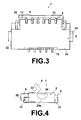
- FIGS. 1 through 4 illustrate the outer appearance of the connector 1, wherein Figure 1 is a plan view, Figure 2 is a front view, Figure 3 is a bottom view, and Figure 4 is a side view. A shield member 30 is omitted from Figures 1 through 4.
- the connector 1 comprises: an insulative housing 2 (hereinafter, simply referred to as "housing") in the form of a flattened parallelepiped; a plurality of contacts 4, which are provided in the housing 2 at predetermined intervals; and a locking member 6, which is pivotally supported by the housing 2 so as to be openable and closable.
- housing insulative housing 2
- contacts 4 which are provided in the housing 2 at predetermined intervals
- locking member 6 which is pivotally supported by the housing 2 so as to be openable and closable.
- a cable receiving recess 8 that opens along the longitudinal direction of the connector 1 is provided in the front side of the housing 2.
- the contacts 4 are provided in parallel along the cable receiving recess 8.
- the "front side” refers to the side of the connector 1, at which a flat cable 100 (hereinafter, simply referred to as "cable") illustrated in Figure 6A is inserted.
- Tines 12 of the contacts 4 protrude toward the side of the bottom surface 2a of the housing 2.
- the tines 12 are surface mounted onto a circuit board 80, when the housing 2 is mounted thereon.
- Figures 5A and 5B are partial sectional views of the connector 1, wherein Figure 5A is a sectional view taken along line 5A-5A of Figure 2, and Figure 5B is a sectional view taken along line 5B-5B of Figure 2.
- the contacts 4 are constituted by two types of contacts, 4a and 4b.
- the contacts 4a are press-fitted into the housing 2 from the rear portion thereof.
- Each contact 4a comprises: a contact arm 10a that protrudes into the cable receiving recess 8, provided at the lower end of the contact 4a; and a pressing arm 11a, provided at the upper end of the contact 4a.
- the contacts 4b are press-fitted into the housing 2 form the front portion thereof.
- Each contact 4b comprises: a contact arm 10b, provided at the lower end of the contact 4b; and a pressing arm 11b, provided at the upper end of the contact 4b.
- the contacts 4a and 4b electrically contact the cable 100 via their contact arms 10a and 10b.
- the pressing arms 11a and 11b press the cable 100 downward, via the locking member 6.
- the locking member 6 is a planar insulative member, and comprises cylindrical axial support portions 14 at each end thereof.
- the axial support portions 14 are press-fitted into corresponding grooves 16 of the housing 2, such that the locking member 6 is rotatably supported by the housing 2.
- Rectangular openings 18 are formed in the locking member 6 at positions corresponding to the pressing arms 11a and 11b, so that the locking member 6 will not interfere with the contacts 4.
- the openings 18 are formed such that they are not open toward the rear end of the locking member 6. Accordingly, the pressing arms 11a and 11b are capable of pressing the cable 100 downward via the locking member 6, by pressing the locking member 6 downward.
- Downwardly protruding cable regulating portions 20 are formed at both ends of the lock member 6 toward the front side thereof.
- the lock member 6 is closed to lock (fix) the cable 100, after the cable 100 is inserted into the cable receiving recess 8 of the housing 2.
- the cable regulating portion 20 regulate horizontal movement of the inserted cable 100, that is, movement in the width direction of the cable 100.
- a substantially semicircular protrusion 24 (engaging portion), which has its curved surface on the bottom thereof, is formed on each side wall 22 of the hosing 2. The protrusions 24 engage with the shield member 6, which will be described later.
- Figures 6A and 6B illustrate the connector 1 in a state in which the shield member 30 is mounted thereon, wherein Figure 6A is a plan view, and Figure 6B is a side view.
- the shield member 30 is formed by punching and bending a single metal plate.
- the material of the shield member is a copper alloy having elasticity, such as phosphor bronze.
- the shield member 6 comprises: a rectangular base 32 that covers the upper surface 2b of the housing 2 (refer to Figure 1); and a pair of substantially rectangular mounting pieces 34, which are bent toward the side walls 22 of the housing 2 from the base 32 and formed into clips.
- the mounting pieces 34 are sized to cover the side walls 22, and have openings 36 (engaging portions) for engaging the protrusions 24 formed therein, at positions that correspond to the protrusions 24.
- the openings 36 have curved surfaces 36a, which are complementary with respect to the curved surfaces 24a (refer to Figure 4) of the protrusions 24.
- the protrusions 24 and the openings 36 serve as pivot points that cause the shield member 30 to move in a see-saw fashion.
- a downwardly protruding curved protrusion 38 is formed at the bottom end of each mounting piece 34, in the vicinity of the opening 36.
- FIG. 7 is a sectional view of the cable 100.
- the cable 100 comprises: a plurality of signal conductors 102, which are arranged parallel at predetermined intervals; and grounding conductors 104, which are arranged at predetermined positions.
- the conductors 102 and 103 are disposed within a molded insulator 106.
- the outer surfaces of the insulator 106 are covered by a conductor 108, such as aluminum foil, to form a shield surface.
- the conductor 108 is provided so as to cover the entire insulator 106.
- the conductor 108 may be provided so as to cover either the upper surface or the lower surface of the insulator 106. In this case, the conductor 108 may be formed on the entire upper or lower surface, or only on a portion thereof.
- Figure 8 is a side view that shows the connector 1 mounted on the circuit board 80.
- the cable 100 is attached to the connector 1 by: opening the locking member 6 to the position illustrated by broken lines in Figure 4; inserting the cable 100 into the connector 1; and closing the locking member 6.
- the shield member 30 is mounted onto the hosing 2. Consequently, the curved protrusions 38 on the mounting pieces 34 abut the circuit board 80, restricting downward displacement of the mounting pieces 34 beyond a certain degree. Thereby, contact between the shield member 30 and the contacts 4, due to excessive descent of the shield member 30, is prevented.
- the shield member 30 is enabled to be mounted on the housing 2 after the cable 100 is attached thereto in this manner.
- the shield member 30 can be mounted onto the housing 2 even if a member that temporarily protrudes from the housing 2, such as the locking member 6, is present.
- the shield member 30 is mounted after the housing 2 is mounted onto the circuit board 80 and after the cable 100 is attached to the housing 2. Therefore, the soldered state of the housing 2 with respect to the circuit board 80 and the connection state of the cable 100 can be easily confirmed prior to mounting the shield member 30.
- the tongue piece 40 contacts the shield surface of the cable 100, and the tongue piece 42 contacts a conductive pad 82 (grounding portion) of the circuit board 80.
- the tongue pieces 40 and 42 of the shield member 30 have elasticity, so they contact the shield surface of the cable 100 and the conductive pad 82 in an elastically urged state. Thereby, the entire housing 2 is covered by the shield member 30, to shield the connector 1.
- the base plate 44 is mounted on the circuit board 80 at a position beneath the tongue piece 40, to support the pressing force exerted thereby onto the cable 100. Thereby, the contact between the shield surface of the cable 100 and the tongue piece 40 is stabilized.
- the material of the base plate 44 is not limited to a particular type, and may be of the same material as that of the circuit board 80. Alternatively, where the base plate 44 is a metallic plate which is soldered onto the grounding portion of the circuit board 80, an electric connection can be established between the base plate 44 and the shield surface formed on the bottom surface of the cable 100.
- the shield member 30 is mounted on the housing 2 such that it is capable of moving in a see-saw fashion, with the curved protrusions 38 as the pivot points. That is, the shield member 30 automatically balances out the difference in reactive forces received by the tongue pieces 40 and 42, by rotating about the curved protrusions 38. Thereby, contact by the tongue pieces 40 and 42 are favorably maintained.
- Figure 9 is a plan view showing the positional relationships
- Figure 10 is a side view showing the positional relationships.
- the cable 100 is indicated by the hatched portions.
- Figure 9 illustrates a state in which electrodes (not shown) at the tip of the cable 100 are in contact with the contacts 4.
- a gap G is secured between the upper surface 2b of the housing 2 and the bottom surface 32a of the base 32 of the shield member 30. The gap G enables see-saw movement of the shield member 30 with the curved protrusions 38 as pivot points, without interfering with the housing 2.
- the present invention is not limited to connectors which are surface mounted onto circuit boards.
- the present invention is applicable to connectors, in which contacts are inserted through and soldered to through holes (apertures) of circuit boards as well.
Abstract
Description
- The present invention relates to an electrical connector for flat cables, which is utilized in electronic devices such as cellular telephones. The present invention also relates to a shield member, which is employed in the electrical connector for flat cables. Particularly, the present invention relates to a shielded (electromagnetic shield) electrical connector for flat cables and a shield member employed therefor.
- Japanese Unexamined Patent Publication No. 2000-231971 (Figure 1, Figure 2) discloses a connector, which is utilized to connect FPC's (Flexible Printed Circuits). This is an example of a known electrical connector for flat cables. This connector comprises a pair of connectors, one on the side of a circuit board, and one on the side of the cable (FPC) . A shell (shield member) is mounted on the exterior of each of the pair of connectors. A grounding conductor of the FPC is connected to the shell of the cable side connector.
- In the known FPC connector, the shells are mounted on the exteriors of housings having predetermined shapes, and are thereby built into the connector. Accordingly, the shielding properties are stable. Where a connector is equipped with a openable/closable locking member, for fixing an FFC (Flexible Flat Cable) or an FPC, the locking member temporarily protrudes toward the exterior of a housing during operation thereof. Therefore, a shielding structure such as that disclosed in the known FPC connector cannot be employed in a connector equipped with a locking member. However, in the case where shells are not mounted on the exteriors of housings, problems such as spurious radiation (electromagnetic waves) being emitted from the connector itself, and external electromagnetic waves entering the electrical paths of the connector arise.
- The present invention has been developed in view of the foregoing circumstances. It is an object of the present invention to provide an electrical connector for flat cables and a shield member to be employed therefor, which have improved EMI (Electro Magnetic Interference) properties.
- According to an aspect of the present invention there is provided an electrical connector for flat cables, comprising:
- a plurality of contacts, for contacting a shield of a flat cable to be inserted into the connector;
- an insulative housing, for holding the contacts, which is to be mounted onto a circuit board having a grounding portion; and
- a shield member, which is mounted on the insulative housing so as to substantially cover the outer surfaces thereof;
- the shield member electrically connecting the shield of the flat cable and the grounding portion of the circuit board when the shield member is mounted on the insulative housing.
- Preferably the shield member comprises: elastic mounting pieces formed as clips, to enable mounting of the shield member onto the insulative hosing in a removable manner; and tongue pieces, provided at a first end and a second end of the shield member; wherein: the tongue piece at the first end elastically contacts the shield of the flat cable and the tongue piece at the second end elastically contacts the grounding portion of the circuit board, when the shield member is mounted on the insulative housing.
- The shield member may be supported in a see-saw fashion, by the mounting pieces, which have pivot points between the first end and the second end.
- Protrusions that contact the circuit board to restrict movement of the shield member toward the circuit board may be provided on the mounting pieces.
- According to another aspect of the present invention there is provided a shield member to be employed in an electrical connector for flat cables to cover the outer surfaces of an insulative housing of the electrical connector, which is mounted on a circuit board, comprising: elastic mounting pieces formed as clips; a tongue piece at a first end of the shield member; and a tongue piece at a second end of the shield member; the tongue piece at the first end elastically contacting a shield of a flat cable and the tongue piece at the second end elastically contacting a grounding portion of the circuit board, when the shield member is mounted on the insulative housing.
- Protrusions that contact the circuit board to restrict movement of the shield member toward the circuit board may be provided on the mounting pieces.
- The electrical connector for flat cables of the present invention comprises the shield member, which is mounted on the insulative housing so as to substantially cover the outer surfaces thereof. The tongue piece at the first end of the shield member contacts the shield of the flat cable and the tongue piece at the second end contacts the grounding portion of the circuit board. Accordingly, the electrical connector for flat cables of the present invention exhibits the following advantageous effects.
- The shield member that covers the insulative housing establishes a grounding path between the flat cable and the grounding portion of the circuit board. Therefore, the EMI properties of the electrical connector for flat cables can be improved.
- A configuration may be adopted, wherein the shield member comprises: the elastic mounting pieces formed as clips, to enable mounting of the shield member onto the insulative hosing in a removable manner; and the tongue pieces, provided at the first end and the second end of the shield member; wherein the tongue piece at the first end elastically contacts the shield of the flat cable and the tongue piece at the second end elastically contacts the grounding portion of the circuit board, when the shield member is mounted on the insulative housing. In this case, the electrical contacts are stable, and the EMI properties are stably improved.
- The shield member may be supported in a seesaw fashion, by the mounting pieces, which have pivot points between the first end and the second end. In this case, the shield member rotates automatically due to the difference in reactive forces of the contacts with the shield of the flat cable and the grounding portion of the circuit board. Therefore, the contacts are established with good balance, maintaining the stability of the electrical contacts.
- Protrusions that contact the circuit board to restrict movement of the shield member toward the circuit board may be provided on the mounting pieces. Consequently, downward movement of the mounting pieces beyond a certain degree is restricted. Therefore, contact with the contacts, due to excessive descent of the shield member, is prevented.
- The shield member of the present invention comprises the elastic mounting pieces formed as clips, and the tongue pieces at the first and second ends thereof. When the shield member is mounted onto the insulative housing, the tongue piece at the first end contacts the shield of the flat cable, and the tongue piece at the second end contacts the grounding portion of the circuit board. Accordingly, the shield member of the present invention exhibits the following advantageous effects.
- The shield member that covers the insulative housing establishes a grounding path between the flat cable and the grounding portion of the circuit board. Therefore, the EMI properties of the electrical connector for flat cables can be improved. Further, the shield member is mounted on the insulative housing via the elastic mounting pieces such that the tongue pieces at the first and second ends elastically contact the shield of the flat cable and the grounding portion of the circuit board, respectively. Therefore, the electrical contacts are stabilized, and the EMI properties are stably improved.
- An embodiment of the present invention will now be described, by way of example only, and with reference to the accompanying schematic drawings, in which:
- Figure 1 is a plan view of an electrical connector for flat cables according to an embodiment of the present invention, with a shield member removed;
- Figure 2 is a front view of the electrical connector for flat cables of Figure 1;
- Figure 3 is a bottom view of the electrical connector for flat cables of Figure 1;
- Figure 4 is a side view of the electrical connector for flat cables of Figure 1;
- Figures 5A and 5B are partial sectional views of the electrical connector for flat cables of Figure 1, wherein Figure 5A is a sectional view taken along line 5A-5A of Figure 2, and Figure 5B is a sectional view taken along line 5B-5B of Figure 2;
- Figures 6A and 6B illustrate the connector for flat cables in a state in which the shield member is mounted thereon, wherein Figure 6A is a plan view, and Figure 6B is a side view;
- Figure 7 is a sectional view that illustrates an example of a flat cable;
- Figure 8 is a side view that illustrates a state in which the connector for flat cables of the present invention is mounted on a circuit board;
- Figure 9 is a plan view that illustrates the positional relationships among an insulative housing, the shield member, the flat cable, and a base plate of the electrical connector for flat cables of the present invention; and
- Figure 10 is a side view that illustrates the positional relationships among the insulative housing, the shield member, the flat cable, and the base plate of the electrical connector for flat cables of the present invention.
- Hereinafter, an electrical connector for flat cables 1 (hereinafter, simply referred to as "connector") according to a preferred embodiment of the present invention will be described, with reference to the attached drawings. Figures 1 through 4 illustrate the outer appearance of the
connector 1, wherein Figure 1 is a plan view, Figure 2 is a front view, Figure 3 is a bottom view, and Figure 4 is a side view. Ashield member 30 is omitted from Figures 1 through 4. Theconnector 1 comprises: an insulative housing 2 (hereinafter, simply referred to as "housing") in the form of a flattened parallelepiped; a plurality ofcontacts 4, which are provided in thehousing 2 at predetermined intervals; and alocking member 6, which is pivotally supported by thehousing 2 so as to be openable and closable. - A cable receiving
recess 8 that opens along the longitudinal direction of theconnector 1 is provided in the front side of thehousing 2. Thecontacts 4 are provided in parallel along the cable receivingrecess 8. Note that the "front side" refers to the side of theconnector 1, at which a flat cable 100 (hereinafter, simply referred to as "cable") illustrated in Figure 6A is inserted.Tines 12 of thecontacts 4 protrude toward the side of the bottom surface 2a of thehousing 2. Thetines 12 are surface mounted onto acircuit board 80, when thehousing 2 is mounted thereon. - Next, the shapes of the
contacts 4 will be described with reference to Figures 5A and 5B. Figures 5A and 5B are partial sectional views of theconnector 1, wherein Figure 5A is a sectional view taken along line 5A-5A of Figure 2, and Figure 5B is a sectional view taken along line 5B-5B of Figure 2. Thecontacts 4 are constituted by two types of contacts, 4a and 4b. Thecontacts 4a are press-fitted into thehousing 2 from the rear portion thereof. Eachcontact 4a comprises: acontact arm 10a that protrudes into thecable receiving recess 8, provided at the lower end of thecontact 4a; and apressing arm 11a, provided at the upper end of thecontact 4a. Thecontacts 4b are press-fitted into thehousing 2 form the front portion thereof. Eachcontact 4b comprises: acontact arm 10b, provided at the lower end of thecontact 4b; and apressing arm 11b, provided at the upper end of thecontact 4b. Thecontacts cable 100 via theircontact arms pressing arms cable 100 downward, via the lockingmember 6. - Next, the locking
member 6 will be described. The lockingmember 6 is a planar insulative member, and comprises cylindricalaxial support portions 14 at each end thereof. Theaxial support portions 14 are press-fitted intocorresponding grooves 16 of thehousing 2, such that the lockingmember 6 is rotatably supported by thehousing 2.Rectangular openings 18 are formed in the lockingmember 6 at positions corresponding to thepressing arms member 6 will not interfere with thecontacts 4. Theopenings 18 are formed such that they are not open toward the rear end of the lockingmember 6. Accordingly, thepressing arms cable 100 downward via the lockingmember 6, by pressing the lockingmember 6 downward. Downwardly protrudingcable regulating portions 20 are formed at both ends of thelock member 6 toward the front side thereof. - The
lock member 6 is closed to lock (fix) thecable 100, after thecable 100 is inserted into thecable receiving recess 8 of thehousing 2. Thecable regulating portion 20 regulate horizontal movement of the insertedcable 100, that is, movement in the width direction of thecable 100. A substantially semicircular protrusion 24 (engaging portion), which has its curved surface on the bottom thereof, is formed on eachside wall 22 of thehosing 2. Theprotrusions 24 engage with theshield member 6, which will be described later. - Next, a state in which the
shield member 6 is mounted on thehousing 2 will be described with reference to Figures 6A and 6B. Figures 6A and 6B illustrate theconnector 1 in a state in which theshield member 30 is mounted thereon, wherein Figure 6A is a plan view, and Figure 6B is a side view. Theshield member 30 is formed by punching and bending a single metal plate. The material of the shield member is a copper alloy having elasticity, such as phosphor bronze. Theshield member 6 comprises: arectangular base 32 that covers theupper surface 2b of the housing 2 (refer to Figure 1); and a pair of substantially rectangular mountingpieces 34, which are bent toward theside walls 22 of thehousing 2 from thebase 32 and formed into clips. The mountingpieces 34 are sized to cover theside walls 22, and have openings 36 (engaging portions) for engaging theprotrusions 24 formed therein, at positions that correspond to theprotrusions 24. Theopenings 36 havecurved surfaces 36a, which are complementary with respect to thecurved surfaces 24a (refer to Figure 4) of theprotrusions 24. Theprotrusions 24 and theopenings 36 serve as pivot points that cause theshield member 30 to move in a see-saw fashion. A downwardly protrudingcurved protrusion 38 is formed at the bottom end of each mountingpiece 34, in the vicinity of theopening 36. - Downwardly extending
tongue pieces shield member 30, respectively. Thetongue piece 40 extends toward thecable 100, and thetip 40a thereof is bent upward. Thetongue piece 42 extends toward thecircuit board 80, and itstip 42a is bent upward in a manner similar to that of thetip 40a. The upwardly bent portions of thetips shield member 30. Note that in Figure 6,reference number 100 denotes the cable, which has been inserted into theconnector 1, andreference number 44 denotes a base plate, separate from thehousing 2. - Here, an example of the
cable 100 will be described with reference to Figure 7. Figure 7 is a sectional view of thecable 100. Thecable 100 comprises: a plurality ofsignal conductors 102, which are arranged parallel at predetermined intervals; and groundingconductors 104, which are arranged at predetermined positions. Theconductors 102 and 103 are disposed within a moldedinsulator 106. The outer surfaces of theinsulator 106 are covered by aconductor 108, such as aluminum foil, to form a shield surface. In the present embodiment, theconductor 108 is provided so as to cover theentire insulator 106. However, theconductor 108 may be provided so as to cover either the upper surface or the lower surface of theinsulator 106. In this case, theconductor 108 may be formed on the entire upper or lower surface, or only on a portion thereof. - Next, a situation in which the
connector 1 is mounted on thecircuit board 80 will be described with reference to Figure 8. Figure 8 is a side view that shows theconnector 1 mounted on thecircuit board 80. Thecable 100 is attached to theconnector 1 by: opening the lockingmember 6 to the position illustrated by broken lines in Figure 4; inserting thecable 100 into theconnector 1; and closing the lockingmember 6. Thereafter, theshield member 30 is mounted onto thehosing 2. Consequently, thecurved protrusions 38 on the mountingpieces 34 abut thecircuit board 80, restricting downward displacement of the mountingpieces 34 beyond a certain degree. Thereby, contact between theshield member 30 and thecontacts 4, due to excessive descent of theshield member 30, is prevented. Theshield member 30 is enabled to be mounted on thehousing 2 after thecable 100 is attached thereto in this manner. Therefore, theshield member 30 can be mounted onto thehousing 2 even if a member that temporarily protrudes from thehousing 2, such as the lockingmember 6, is present. In addition, theshield member 30 is mounted after thehousing 2 is mounted onto thecircuit board 80 and after thecable 100 is attached to thehousing 2. Therefore, the soldered state of thehousing 2 with respect to thecircuit board 80 and the connection state of thecable 100 can be easily confirmed prior to mounting theshield member 30. - The
tongue piece 40 contacts the shield surface of thecable 100, and thetongue piece 42 contacts a conductive pad 82 (grounding portion) of thecircuit board 80. Thetongue pieces shield member 30 have elasticity, so they contact the shield surface of thecable 100 and theconductive pad 82 in an elastically urged state. Thereby, theentire housing 2 is covered by theshield member 30, to shield theconnector 1. Thebase plate 44 is mounted on thecircuit board 80 at a position beneath thetongue piece 40, to support the pressing force exerted thereby onto thecable 100. Thereby, the contact between the shield surface of thecable 100 and thetongue piece 40 is stabilized. The material of thebase plate 44 is not limited to a particular type, and may be of the same material as that of thecircuit board 80. Alternatively, where thebase plate 44 is a metallic plate which is soldered onto the grounding portion of thecircuit board 80, an electric connection can be established between thebase plate 44 and the shield surface formed on the bottom surface of thecable 100. - In this manner, the
shield member 30 is mounted on thehousing 2 such that it is capable of moving in a see-saw fashion, with thecurved protrusions 38 as the pivot points. That is, theshield member 30 automatically balances out the difference in reactive forces received by thetongue pieces curved protrusions 38. Thereby, contact by thetongue pieces - Next, the positional relationships among the
housing 2, theshield member 30, thecable 100, and thebase plate 44 will be described with reference to Figures 9 and 10. Figure 9 is a plan view showing the positional relationships, and Figure 10 is a side view showing the positional relationships. Note that in Figures 9 and 10, thecable 100 is indicated by the hatched portions. Figure 9 illustrates a state in which electrodes (not shown) at the tip of thecable 100 are in contact with thecontacts 4. In addition, as illustrated in Figure 10, a gap G is secured between theupper surface 2b of thehousing 2 and thebottom surface 32a of thebase 32 of theshield member 30. The gap G enables see-saw movement of theshield member 30 with thecurved protrusions 38 as pivot points, without interfering with thehousing 2. - A preferred embodiment of the present invention has been described above. However, the present invention is not limited to connectors which are surface mounted onto circuit boards. The present invention is applicable to connectors, in which contacts are inserted through and soldered to through holes (apertures) of circuit boards as well.
Note that "flat cables" include FFC's, in which a plurality of wires are arranged in parallel within a planar insulator, and FPC's, in which conductive paths are printed on a flexible circuit board.
Claims (6)
- An electrical connector for flat cables (1), comprising:a plurality of contacts (4), for contacting a shield of a flat cable (100) to be inserted into the connector (1);an insulative housing (2), for holding the contacts (4), which is to be mounted onto a circuit board (80) having a grounding portion (82); anda shield member (30), which is mounted on the insulative housing (2) so as to substantially cover the outer surfaces thereof;the shield member (30) electrically connecting the shield of the flat cable (100)and the grounding portion (82) of the circuit board (80) when the shield member (30) is mounted on the insulative housing (2).
- An electrical connector for flat cables (1) as defined in claim 1, wherein the shield member (30) comprises:elastic mounting pieces (34) formed as clips, to enable mounting of the shield member (30) onto the insulative housing (2) in a removable manner; andtongue pieces (40, 42), provided at a first end and a second end of the shield member (30); wherein:the tongue piece (40) at the first end elastically contacts the shield of the flat cable (100) and the tongue piece (42)at the second end elastically contacts the grounding portion (82) of the circuit board (80), when the shield member (30) is mounted on the insulative housing (2).
- An electrical connector for flat cables (1) as defined in claim 2, wherein:the shield member (30) is supported in a see-saw fashion, by the mounting pieces (34), which have pivot points (24, 36) between the first end and the second end.
- An electrical connector for flat cables (1) as defined in either claim 2 or claim 3, wherein:protrusions (38) that contact the circuit board (80) to restrict movement of the shield member (30) toward the circuit board (80) are provided on the mounting pieces (34).
- A shield member (30) to be employed in an electrical connector for flat cables (1) to cover the outer surfaces of an insulative housing (2) of the electrical connector (1), which is mounted on a circuit board (80), comprising:elastic mounting pieces (34) formed as clips;a tongue piece (40) at a first end of the shield member; anda tongue piece (42) at a second end of the shield member; whereinthe tongue piece (40) at the first end elastically contacts a shield of a flat cable (100) and the tongue piece (42) at the second end elastically contacts a grounding portion (82) of the circuit board (80), when the shield member (30) is mounted on the insulative housing (2).
- A shield member (30) as defined in claim 5, wherein:protrusions (38) that contact the circuit board (80) to restrict movement of the shield member (30) toward the circuit board (80) are provided on the mounting pieces (34).
Applications Claiming Priority (1)
| Application Number | Priority Date | Filing Date | Title |
|---|---|---|---|
| JP2004247844A JP2006066242A (en) | 2004-08-27 | 2004-08-27 | Electric connector for flat cable and shield member used for same |
Publications (2)
| Publication Number | Publication Date |
|---|---|
| EP1630902A2 true EP1630902A2 (en) | 2006-03-01 |
| EP1630902A3 EP1630902A3 (en) | 2007-11-14 |
Family
ID=35385518
Family Applications (1)
| Application Number | Title | Priority Date | Filing Date |
|---|---|---|---|
| EP05107462A Withdrawn EP1630902A3 (en) | 2004-08-27 | 2005-08-12 | An electrical connector and a shield member for flat cables. |
Country Status (5)
| Country | Link |
|---|---|
| US (1) | US7261595B2 (en) |
| EP (1) | EP1630902A3 (en) |
| JP (1) | JP2006066242A (en) |
| KR (1) | KR101158929B1 (en) |
| CN (1) | CN1747243A (en) |
Families Citing this family (15)
| Publication number | Priority date | Publication date | Assignee | Title |
|---|---|---|---|---|
| US7244125B2 (en) | 2003-12-08 | 2007-07-17 | Neoconix, Inc. | Connector for making electrical contact at semiconductor scales |
| US7758351B2 (en) | 2003-04-11 | 2010-07-20 | Neoconix, Inc. | Method and system for batch manufacturing of spring elements |
| US8584353B2 (en) | 2003-04-11 | 2013-11-19 | Neoconix, Inc. | Method for fabricating a contact grid array |
| US7114961B2 (en) | 2003-04-11 | 2006-10-03 | Neoconix, Inc. | Electrical connector on a flexible carrier |
| US7383632B2 (en) | 2004-03-19 | 2008-06-10 | Neoconix, Inc. | Method for fabricating a connector |
| JP4199272B2 (en) * | 2006-08-23 | 2008-12-17 | 日本航空電子工業株式会社 | connector |
| KR100871926B1 (en) * | 2007-01-19 | 2008-12-05 | 전상철 | Housing Connector For Flexible Flat Cable |
| KR100951073B1 (en) * | 2007-03-22 | 2010-04-05 | 주식회사 후성테크 | Ffc/fpc cable connector |
| JP5004233B2 (en) * | 2007-11-08 | 2012-08-22 | 株式会社ヨコオ | Relay connector |
| JP5571398B2 (en) * | 2010-01-26 | 2014-08-13 | 京セラコネクタプロダクツ株式会社 | Connector cover member |
| JP5344059B2 (en) * | 2011-03-18 | 2013-11-20 | 第一精工株式会社 | Electrical connector |
| US8641428B2 (en) | 2011-12-02 | 2014-02-04 | Neoconix, Inc. | Electrical connector and method of making it |
| US9680273B2 (en) | 2013-03-15 | 2017-06-13 | Neoconix, Inc | Electrical connector with electrical contacts protected by a layer of compressible material and method of making it |
| JP6199153B2 (en) * | 2013-10-25 | 2017-09-20 | 日本航空電子工業株式会社 | connector |
| JP2016066478A (en) * | 2014-09-24 | 2016-04-28 | 第一精工株式会社 | Electric connector |
Citations (4)
| Publication number | Priority date | Publication date | Assignee | Title |
|---|---|---|---|---|
| WO1986002781A1 (en) * | 1984-10-30 | 1986-05-09 | Amp Incorporated | Shielded electrical connector |
| US4944690A (en) * | 1988-01-14 | 1990-07-31 | Amp Incorporated | Electrical connector for flat electrical cables |
| US5882223A (en) * | 1996-02-21 | 1999-03-16 | Japan Aviation Delectronics Industry, Limited | Connector which is adapted to connect a flat connection object having a signal pattern and a shield pattern opposite to each other |
| US6345998B1 (en) * | 2001-05-04 | 2002-02-12 | Super Link Electronics Co., Ltd. | Flexible printed circuit connector |
Family Cites Families (7)
| Publication number | Priority date | Publication date | Assignee | Title |
|---|---|---|---|---|
| US5961348A (en) * | 1996-03-01 | 1999-10-05 | Molex Incorporated | System for terminating the shield of a high speed cable |
| JP3196018B2 (en) * | 1997-03-31 | 2001-08-06 | 日本航空電子工業株式会社 | Relay connector with shield mechanism |
| JP3451393B2 (en) * | 1998-01-30 | 2003-09-29 | 日本航空電子工業株式会社 | Plug connector and socket connector |
| US6183281B1 (en) * | 1999-10-20 | 2001-02-06 | Hon Hai Precision Ind. Co., Ltd. | Electrical connector |
| JP2001135392A (en) * | 1999-10-29 | 2001-05-18 | Smk Corp | Flat cable connector |
| JP3887694B2 (en) * | 2001-12-14 | 2007-02-28 | 住友電装株式会社 | Flat cable connector |
| US6932648B1 (en) * | 2004-08-02 | 2005-08-23 | P-Two Industries Inc. | Flexible printed circuit connector capable of preventing electromagnetic interference |
-
2004
- 2004-08-27 JP JP2004247844A patent/JP2006066242A/en not_active Withdrawn
-
2005
- 2005-08-10 KR KR1020050073405A patent/KR101158929B1/en active IP Right Grant
- 2005-08-12 EP EP05107462A patent/EP1630902A3/en not_active Withdrawn
- 2005-08-26 US US11/212,278 patent/US7261595B2/en not_active Expired - Fee Related
- 2005-08-29 CN CNA2005100976363A patent/CN1747243A/en active Pending
Patent Citations (4)
| Publication number | Priority date | Publication date | Assignee | Title |
|---|---|---|---|---|
| WO1986002781A1 (en) * | 1984-10-30 | 1986-05-09 | Amp Incorporated | Shielded electrical connector |
| US4944690A (en) * | 1988-01-14 | 1990-07-31 | Amp Incorporated | Electrical connector for flat electrical cables |
| US5882223A (en) * | 1996-02-21 | 1999-03-16 | Japan Aviation Delectronics Industry, Limited | Connector which is adapted to connect a flat connection object having a signal pattern and a shield pattern opposite to each other |
| US6345998B1 (en) * | 2001-05-04 | 2002-02-12 | Super Link Electronics Co., Ltd. | Flexible printed circuit connector |
Also Published As
| Publication number | Publication date |
|---|---|
| KR101158929B1 (en) | 2012-06-21 |
| EP1630902A3 (en) | 2007-11-14 |
| US7261595B2 (en) | 2007-08-28 |
| US20060046559A1 (en) | 2006-03-02 |
| JP2006066242A (en) | 2006-03-09 |
| KR20060050390A (en) | 2006-05-19 |
| CN1747243A (en) | 2006-03-15 |
Similar Documents
| Publication | Publication Date | Title |
|---|---|---|
| EP1630902A2 (en) | An electrical connector and a shield member for flat cables. | |
| US6066000A (en) | Two-piece electrical connector having a cable connector with a single metallic shell holding a cable fixture | |
| EP0405454B1 (en) | Coaxial contact element | |
| US7189090B2 (en) | Coupler for flat cables and electrical connector assembly | |
| US5454734A (en) | Electrical connection system | |
| US7520774B2 (en) | Micro coaxial cable connector assembly | |
| US5035649A (en) | Shielded electrical connectors | |
| US8092254B2 (en) | Wire to board connector with multiple contact points | |
| EP0933837A1 (en) | Plug connector and socket connector | |
| WO2002058191A3 (en) | Shielded electrical connector | |
| US20060121782A1 (en) | Electrical connector having an improved grounding path | |
| JP6859998B2 (en) | Electrical connectors and connector devices | |
| KR101125067B1 (en) | Connector for coaxial cable | |
| CN101355203A (en) | Board connector, mating connector, and electronic device inc.luding the same | |
| JP3104176B2 (en) | Electrical connector for coaxial cable | |
| EP3316406B1 (en) | Electronic device and connector | |
| JPH09509278A (en) | Connector assembly | |
| CN102771014B (en) | Electrical connector and electrical connector assembly | |
| EP1037314B1 (en) | Receptacle and printed circuit assembly for receiving a plug | |
| US20080176435A1 (en) | Electrical Connector for Flat Cable | |
| US6354876B1 (en) | Electronic card connector having improved grounding plate | |
| EP1193811A1 (en) | Electrical connector | |
| US6793538B2 (en) | Slim modular jack | |
| JP7176659B2 (en) | electrical connector | |
| JP7148009B2 (en) | electrical connector |
Legal Events
| Date | Code | Title | Description |
|---|---|---|---|
| PUAI | Public reference made under article 153(3) epc to a published international application that has entered the european phase |
Free format text: ORIGINAL CODE: 0009012 |
|
| AK | Designated contracting states |
Kind code of ref document: A2 Designated state(s): AT BE BG CH CY CZ DE DK EE ES FI FR GB GR HU IE IS IT LI LT LU LV MC NL PL PT RO SE SI SK TR |
|
| AX | Request for extension of the european patent |
Extension state: AL BA HR MK YU |
|
| PUAL | Search report despatched |
Free format text: ORIGINAL CODE: 0009013 |
|
| AK | Designated contracting states |
Kind code of ref document: A3 Designated state(s): AT BE BG CH CY CZ DE DK EE ES FI FR GB GR HU IE IS IT LI LT LU LV MC NL PL PT RO SE SI SK TR |
|
| AX | Request for extension of the european patent |
Extension state: AL BA HR MK YU |
|
| AKX | Designation fees paid | ||
| STAA | Information on the status of an ep patent application or granted ep patent |
Free format text: STATUS: THE APPLICATION IS DEEMED TO BE WITHDRAWN |
|
| REG | Reference to a national code |
Ref country code: DE Ref legal event code: 8566 |
|
| 18D | Application deemed to be withdrawn |
Effective date: 20080304 |