EP1632893A2 - Device service provider interface - Google Patents
Device service provider interface Download PDFInfo
- Publication number
- EP1632893A2 EP1632893A2 EP05107826A EP05107826A EP1632893A2 EP 1632893 A2 EP1632893 A2 EP 1632893A2 EP 05107826 A EP05107826 A EP 05107826A EP 05107826 A EP05107826 A EP 05107826A EP 1632893 A2 EP1632893 A2 EP 1632893A2
- Authority
- EP
- European Patent Office
- Prior art keywords
- component
- rfid
- provider
- interface
- dspi
- Prior art date
- Legal status (The legal status is an assumption and is not a legal conclusion. Google has not performed a legal analysis and makes no representation as to the accuracy of the status listed.)
- Withdrawn
Links
Images


Classifications
-
- G—PHYSICS
- G06—COMPUTING; CALCULATING OR COUNTING
- G06Q—INFORMATION AND COMMUNICATION TECHNOLOGY [ICT] SPECIALLY ADAPTED FOR ADMINISTRATIVE, COMMERCIAL, FINANCIAL, MANAGERIAL OR SUPERVISORY PURPOSES; SYSTEMS OR METHODS SPECIALLY ADAPTED FOR ADMINISTRATIVE, COMMERCIAL, FINANCIAL, MANAGERIAL OR SUPERVISORY PURPOSES, NOT OTHERWISE PROVIDED FOR
- G06Q10/00—Administration; Management
- G06Q10/08—Logistics, e.g. warehousing, loading or distribution; Inventory or stock management
-
- G—PHYSICS
- G06—COMPUTING; CALCULATING OR COUNTING
- G06K—GRAPHICAL DATA READING; PRESENTATION OF DATA; RECORD CARRIERS; HANDLING RECORD CARRIERS
- G06K17/00—Methods or arrangements for effecting co-operative working between equipments covered by two or more of main groups G06K1/00 - G06K15/00, e.g. automatic card files incorporating conveying and reading operations
Abstract
Description
- This application claims the benefit of U.S. Provisional Patent Application Serial No. 60/606,281 filed on September 1, 2004, entitled "SYSTEM AND METHODS THAT FACILITATE RFID SERVER PROGRAMMING MODEL AND API'S," and U.S. Provisional Patent Application Serial No. 60/606,577 filed on September 2, 2004, entitled "FACILITATE RFID SERVER PROGRAMMING MODEL AND API'S." This application is also related to co-pending U.S. Patent Application Serial Nos. , _____, and _____, filed on _____, _____, and _____, respectively. The entireties of these applications are incorporated herein by reference.
- The subject invention generally relates to radio frequency identification (RFID), and more particularly to a system and/or a method that facilitates providing uniform RFID communication and management.
- Many retail, manufacture, and distribution establishments are applying different and innovative operating methods to increase efficiency. These establishments can monitor store inventory to facilitate optimizing supply and demand relating to consumers. One aspect of maximizing profit hinges on properly stocking inventory such that replenishment occurs in conjunction with exhaustion of goods and/or products. For example, a retailer selling a computer and/or a VCR, must stock the computer in relation to its consumer sales, and the VCR in relation to its consumer sales. Thus, if the computer is in higher demand (e.g., more units sold) than the VCR, the retailer can stock the computer more frequently in order to optimize supply and demand, and in turn, profit. Monitoring inventory and associated sales can be a complex task, wherein product activity is comparable to a black box since inner workings are unknown; yet monitoring products is a crucial element in inventory/product efficiency.
- One type of monitoring system relating to products is a portable image collection device (e.g., barcode reader), which is widely used in manufacturing, service and/or package delivery industries. Such devices can perform a variety of on-site data collection activities. Portable data collection devices often include integrated bar code dataform readers adapted to read bar code dataforms affixed to products, product packaging and/or containers in warehouses, retail stores, shipping terminals, for inventory control, tracking, production control and expediting, quality assurance and/or other purposes.
- A unique bar code can be placed on a product, wherein the bar code can be associated with information relating to that product. A bar-code scanner can be utilized to scan the barcode on the product, and product related information can be retrieved threrefrom. Such identifying information, however, is aesthetically displeasing as such information can clutter the product. Moreover, tears, smudges, annotation or other physical damage/alteration to a barcode can render such conventional systems and/or methodologies substantially useless. If a portion of a bar code is torn from the product, a bar code scanner may not be able to correctly read the bar code. Similarly, a smudge on a product can render such barcode unreadable.
- Monitoring systems and/or methods utilizing barcode readers and a universal product code (UPC) confront a user (e.g., retailer, distributor, manufacturer, ...) with additional complications. Barcode readers require a line of sight in order to properly monitor products. For example, a typical barcode system requires a scanner to be within 4-8 inches of a barcode and/or UPC to achieve a proper read. Not only does a barcode system require line of sight, manual scans are necessary on each individual product in order to identify the product. Moreover, a single barcode and/or UPC must represent all instances of a product (e.g., a bottle of ketchup of brand Tomato is designated a single UPC and/or barcode for representation of the product). In addition, the amount of information associated to the single barcode and/or UPC is limited. Thus, a scanning of brand Tomato ketchup can give the product identification and a price. Not only is the information insubstantial, but the information is not conducive to real-time product monitoring.
- Automatic identification and data capture (AIDC) technology, specifically, Radio Frequency Identification (RFID) has been developed based at least upon the need to cure the above deficiencies of monitoring systems and/or methodologies (e.g., barcode readers, barcodes, and/or UPCs). RFID is a technique of remotely storing and retrieving data utilizing RFID tags. Since RFID systems are based upon radio frequency and associated signals, numerous benefits and/or advantages precede traditional techniques in monitoring products. RFID technology does not require a line of sight in order to monitor products and/or receive signals from RFID tags. Thus, no manual scan is necessary wherein the scanner is required to be in close proximity of the target (e.g., product). Yet, range is limited in RFID based upon radio frequency, RFID tag size, and associated power source. Additionally, RFID systems allow multiple reads within seconds providing quick scans and identification. In other words, an RFID system allows a plurality of tags to be read and/or identified when the tags are within a range of an RFID reader. The capability of multiple reads in an RFID system is complimented with the ability of providing informational tags that contain a unique identification code to each individual product. Therefore, in contrast to a barcode system, each bottle of ketchup made by brand Tomato would have an associated identification code. For example, two bottles of ketchup made by brand Tomato have two distinct identification codes associated thereto within an RFID system; whereas in barcode systems, the two bottles of ketchup made by brand Tomato would have the same barcode and/or UPC. In another example, RFID systems and/or methods can be implemented in water such as tracking and/or monitoring underwater pipe, whereas a barcode monitoring system presents numerous complications under such conditions.
- Moreover, RFID systems and/or methodologies provide real-time data associated to a tagged item. Real-time data streams allow a retailer, distributor, and/or manufacturer the ability to monitor inventory and/or products with precision. Utilizing RFID can further facilitate supplying products on a front-end distribution (e.g., retailer to consumer) and a back-end distribution (e.g., distributor/manufacturer to retailer). Distributors and/or manufacturers can monitor shipments of goods, quality, amount, shipping time, etc. In addition, retailers can track the amount of inventory received, location of such inventory, quality, shelf life, etc. The described benefits demonstrate the flexibility of RFID technology to function across multiple domains such as, front-end supply, back-end supply, distribution chains, manufacturing, retail, automation, etc.
- An RFID system consists of at least an RFID tag and a RFID transceiver. The RFID tag can contain an antenna that provides reception and/or transmission to radio frequency queries from the RFID transceiver. The RFID tag can be a small object, such as, for example, an adhesive sticker, a flexible label and integrated chip, etc. There are typically four different frequencies the RFID tags utilize: low frequency tags (between 125 to 134 kilohertz), high frequency tags (13.56 megahertz), UHF tags (868 to 956 megahertz) and Microwave tags (2.45 gigahertz).
- Within the various frequency ranges, RFID tags can be either passive or active. A passive RFID tag does not include a power supply. When electrical current is induced in the antenna by the received radio frequency from an RFID transceiver, sufficient power is provided for the tag to respond. In many instances, the passive RFID tag response is brief, consisting of an ID number (e.g., Globally Unique Identifier (GUID)). A GUID is a pseudo-random number that is unique and can be implemented by a standard Universally Unique Identifier (UUID) (e.g., a 16-byte number written in hexadecimal format). However, RFID systems and/or methods have converged on storing information in, for instance, multi-bit format (e.g., 64 bit or 96 bit) called a electronic product code (EPC). The lack of power supply in the passive RFID tag allows the device to be small and cost-efficient. Some passive RFID tags are measured to be .4 mm x .4 mm, with a thickness thinner than a sheet of paper. Yet, the absence of the power supply limits the practical read range of the passive RFID tag from 10 mm to about 5 meters.
- An active RFID tag contains a power source providing longer read ranges. A typical active RFID tags are about the size of a U.S. currency coin, and provides providing read ranges of about tens of meters, while maintaining a battery life of up to several years. Furthermore, active RFID tags can be read and/or written. For instance, RFID tags can provide an additional security layer to deter theft by writing to an active RFID tag. A security bit can determine a security status based at least upon a RFID transceiver. In one security system, for example, an active RFID tag can have a security bit set/written to one, which can indicate the product is not cleared to leave a secure area without triggering an alarm/warning. Once the appropriate conditions exist, the RFID system and/or method can write the bit on the tag to a zero, which can indicate the tagged product is cleared to leave the secure area.
- In general, an RFID system can include multiple components: tags, tag readers (e.g., tag transceivers), tag-programming stations, circulation readers, sorting equipment, tag inventory wands, etc. Moreover, various makes, models, types, and/or applications can be associated with respective components (e.g., tag, tag readers, tag programming stations, circulation readers, sorting equipment, tag inventory wands, ...), which can complicate discovery, configuration, setup, communication, maintenance, security, and/or compatibility within the RFID system and with other RFID systems. In view of the above, there is a need to provide a uniform way to discover, configure, setup, and communicate to RFID devices in respect to the maker and associated specifications.
- The following presents a simplified summary of the invention in order to provide a basic understanding of some aspects of the invention. This summary is not an extensive overview of the invention. It is intended to neither identify key or critical elements of the invention nor delineate the scope of the invention. Its sole purpose is to present some concepts of the invention in a simplified form as a prelude to the more detailed description that is presented later.
- The subject invention relates to systems and/or methods that facilitate interacting with a radio frequency identification (RFID) device and/or other real-time event generation systems (e.g., a sensor, a web service, ...). A device service provider interface (DSPI) component can provide an abstraction layer to communicate and manage device(s) in a uniform manner regardless of the device's type and/or brand. In particular, the DSPI component defines at least one interface for a device vendor (e.g., reader vendor) to provide a service to an RFID server uniformly. Thus, the DSPI component is a layer between the server and at least one device. Moreover, the DSPI component can define an interface to handle: discovery, configuration, communication, and connection management.
- In accordance with one aspect of the subject invention, the DSPI component can include a receiver component that receives one or more of a protocol translation that relates to a device, RFID server data, RFID device data, etc. The DSPI component facilitates communicating uniformly to the device and exposing functionality of the device regardless of a device vendor and the protocol standard. In addition, the receiver component can be either external and/or internal in relation to the DSPI component. It is to be appreciated that a device can be, but is not limited to, an RFID reader, an RFID writer, an RFID transmitter, an RFID device, a sensor, a real-time generation system, a real-time sensor, a device extensible to a web service, and a real-time event generation system, ...
- In accordance with another aspect of the subject invention, the DSPI component can include a request response component that defines a message exchange in the device layer. It is to be appreciated that the message exchange can be asynchronous. Furthermore, the message exchange can be a request response pair, a notification, a command, and/or a property. The message exchange is utilized by the request response component, wherein the message exchange is markup language syntax between the RFID server and at least one RFID device. The markup language can be, but is not limited to, an extensible markup language (XML), a hypertext markup language (HTML), a standard generalized markup language (SGML), and an extensible hypertext markup language (XHTML).
- Furthermore, the DSPI component can include a device interface component that defines a message layer and/or a transport layer. The device interface component provides the messaging and connecting management between the RFID server and at least one RFID device. The device interface component can utilize markup language syntax in order to send and/or receive messages (e.g., notification, response, request, ...).
- In yet another aspect of the subject, the DSPI component can include a device discovery interface component that discovers RFID devices. Thus, the device discovery interface component can define an interface that can inform and/or report new RFID device(s). In order to be efficient, the device discovery interface component can instantiate one component per provider. Furthermore, the DSPI component can include an SPI container component that facilitates loading the DSPI provider into the RFID server. The SPI container component maintains version-ability between the RFID server and the SPI. Moreover, the SPI container component can register at least one driver with the RFID server.
- The following description and the annexed drawings set forth in detail certain illustrative aspects of the invention. These aspects are indicative, however, of but a few of the various ways in which the principles of the invention may be employed and the subject invention is intended to include all such aspects and their equivalents. Other advantages and novel features of the invention will become apparent from the following detailed description of the invention when considered in conjunction with the drawings.
- Fig. 1 illustrates a block diagram of an exemplary system that facilitates interacting with a device component.
- Fig. 2 illustrates a block diagram of an exemplary system that facilitates interacting with a device.
- Fig. 3 illustrates a block diagram of an exemplary system that facilitates interacting with a device within a radio frequency identification system.
- Fig. 4 illustrates a block diagram of an exemplary system that facilitates communicating with a device.
- Fig. 5 illustrates a block diagram of an exemplary system that facilitates communicating with a device.
- Fig. 6 illustrates a block diagram of an exemplary system that facilitates communicating with a device.
- Fig. 7 illustrates a block diagram of an exemplary system that facilitates communicating with a device.
- Fig. 8 illustrates a block diagram of an exemplary system that facilitates communicating with a plurality of devices and associated providers.
- Fig. 9 illustrates a block diagram of an exemplary system that facilitates interacting with a device.
- Fig. 10 illustrates a flow chart of an exemplary methodology that facilitates providing uniform services for a device.
- Fig. 11 illustrates a flow chart of an exemplary methodology that facilitates providing uniform services for a device.
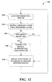
- Fig. 12 illustrates a flow chart of an exemplary methodology that facilitates providing uniform services for a device.
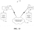
- Fig. 13 illustrates an exemplary networking environment, wherein the novel aspects of the subject invention can be employed.
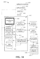
- Fig. 14 illustrates an exemplary operating environment, wherein the novel aspects of the subject invention can be employed.
- As utilized in this application, terms "component," "system," and the like are intended to refer to a computer-related entity, either hardware, software (e.g., in execution), and/or firmware. For example, a component can be a process running on a processor, a processor, an object, an executable, a program, and/or a computer. By way of illustration, both an application running on a server and the server can be a component. One or more components can reside within a process and a component can be localized on one computer and/or distributed between two or more computers.
- The subject invention is described with reference to the drawings, wherein like reference numerals are used to refer to like elements throughout. In the following description, for purposes of explanation, numerous specific details are set forth in order to provide a thorough understanding of the subject invention. It may be evident, however, that the subject invention may be practiced without these specific details. In other instances, well-known structures and devices are shown in block diagram form in order to facilitate describing the subject invention.
- Artificial intelligence based systems (e.g., explicitly and/or implicitly trained classifiers) can be employed in connection with performing inference and/or probabilistic determinations and/or statistical-based determinations as described herein. As used herein, the term "inference" refers generally to the process of reasoning about or inferring states of the system, environment, and/or user from a set of observations as captured via events and/or data. Inference can be employed to identify a specific context or action, or can generate a probability distribution over states, for example. The inference can be probabilistic - that is, the computation of a probability distribution over states of interest based on a consideration of data and events. Inference can also refer to techniques employed for composing higher-level events from a set of events and/or data. Such inference results in the construction of new events or actions from a set of observed events and/or stored event data, whether or not the events are correlated in close temporal proximity, and whether the events and data come from one or several event and data sources. Various classification schemes and/or systems (e.g., support vector machines, neural networks, expert systems, Bayesian belief networks, fuzzy logic, data fusion engines... ) can be employed in connection with performing automatic and/or inferred action in connection with the subject invention.
- Now turning to the figures, Fig. 1 illustrates a
system 100 that facilitates interacting with a device component to provide uniform communication and/or management. Thesystem 100 can employ adevice interface component 102 to provide an abstraction layer that communicates and manages adevice component 104 in a uniform manner. Thedevice interface component 102 can act as a "middle intermediary" between aserver 106 and the at least onedevice component 104. Theserver 106 can be, for example, an RFID server, wherein at least one service (e.g., publish, subscribe, query, poll, manage, monitor, update, etc.) and/or programmed computer process (e.g., related to manufacturing and/or shipping, etc.) can be provided to thedevice component 104. Furthermore, thedevice interface component 102 can include areceiver component 108 that receives one or more of server data, a protocol translation that relates to a device, RFID server data, RFID device data, etc. It is to be appreciated that thedevice interface component 102 facilitates communicating uniformly to the device and exposing functionality of the device regardless of a device vendor and the protocol standard.. In addition, thereceiver component 108 can be either external and/or internal in relation to thedevice interface component 102. It is to be further appreciated that a device can be, but is not limited to, an RFID reader, an RFID writer, an RFID transmitter, an RFID device, a device, real-time sensor, a sensor, a device extensible to a web service, and a real-time event generation system, ... - Device vendors (e.g., individual hardware vendor (IHV) that specialize in hardware manufacturing of a specific type of hardware device and associated software driver) can utilize the
device interface component 102 in order to provide services to middleware products based at least in part upon the plethora of devices and associated command sets. In other words, one device from a vendor can utilize one set of commands, while another device can utilize a substantially different set of commands. To mitigate the problems relating to the various vendors and command sets, thedevice interface component 102 can define an interface for a device vendor that provides services to theserver 106 in a uniform manner. Therefore,server 106 can utilize thedevice interface component 102 to interact with thedevice component 104 with a uniform technique that provides device flexibility. Moreover, thedevice interface component 102 can provide an interface and/or interfaces to delegate discovery, configuration, communication, and connection management of thedevice component 104. It is to be appreciated thedevice interface component 102 can interact withnumerous device components 104, wherein provider(s) are associated to eachdevice component 104. - For instance, various legacy systems (e.g., wherein a legacy system is typically a reader and/or device that have proprietary protocols for communication that are obsolete in the face of new standards) by definition utilize obsolete devices and/or software. These legacy systems can employ the
device interface component 102 allowing an interface and/or interfaces to provide multiple legacy devices and providers a uniform interaction with theserver 106. Thus, theobsolete device component 104 and associated provider (not shown) can be utilized to provide a variety of services and/or processes via thedevice interface component 102 andserver 106. - In one example, the
device interface component 102 can be utilized in order to provide a uniform technique for interaction between a plurality ofdevice components 104 and aserver 106. Thedevice components 104 can be, for instance, legacy devices, auto-identification devices, EPC-Crlobal compliant devices, etc. Additionally, it is to be appreciated that eachdevice component 104 can have an associated provider (e.g., EPC-G compliant provider, proprietary provider, legacy provider, ...). Thus, thedevice interface component 102 can provide a uniform interaction between multiple providers utilizing various command sets fordevice components 104 and aserver 106. - The
device interface component 102 can provide normalization across multiple standards representative of thenumerous device components 104, a web service, and/or real time event generation systems (not shown). Thus, thedevice components 104 can be an RFID device and/or a sensor device. Furthermore, utilizing thedevice interface component 102 enables hardware innovations to surface to a higher level. Thedevice interface component 102 can be implemented by a provider (not shown), which can be, for instance, a processor independent platform assembly. The provider can implement an interface and/or interfaces defined by thedevice interface component 102. By defining the interface for the provider, thedevice interface component 102 interacts with thedevice component 104 by employing device specific commands. Thus, thedevice interface component 102 minimizes device specific details from theRFID server 106. - Fig. 2 illustrates a
system 200 that provides an overview in respect to the novelty of the subject invention. For instance, an RFID device vendor needs a uniform way of providing their services to a host layer running on an operating system platform, as each device supports a different command set, a protocol(s), and/or behavior. The Device Service Provider Interface (DSPI) is an abstraction layer for an RFID services platform to communicate with and manage RFID devices uniformly. This layer provides for normalization across multiple communication protocols, support for Legacy Readers and other Auto-ID devices in uniform manner, as well as providing the ability to surface key hardware innovations to the higher layers. - The DSPI defines the abstract classes (for handling discovery, configuration, communication, and device & connection management) that device vendors can implement to provide services to the RFID services platform on the operating system in a uniform way. The providers can run under a RFID services host 202 as a managed entity, and could communicate with the device 204 and/or devices 204 itself via, for example, managed API, unmanaged code, a COM implementation, or Win 32 API's, based on the transport supported referred to as a
host machine 206. - In particular, a process
instance app domain 208 can contain aprocess instance 210, wherein the processinstance app domain 208 can interact with at least one deviceprovider app domain 212. The deviceprovider app domain 212 can contain aDSPI implementation 214 for a device, wherein there can be a plurality ofdevices 216 associated therewith. It is to be appreciated that there can be one to N devices, wherein N is an integer as depicted in the figure. - Device Service Providers would fall under at least one of the following categories: 1) Pure Managed code implementation using one of the standard protocols [HTTP, TCP, SERIAL (e.g., Samsys); 2) Managed code protocol implementation but calling unmanaged code (e.g. USB Reader device, a proxy connecting to a different protocol handler process); 3) Managed code wrapper for a proprietary protocol implemented as windows device driver (e.g., Pure Printer drivers such as SATO)
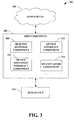
- Fig. 3 illustrates a
system 300 that facilitates interacting with a device to provide uniform techniques for communication and/or management. AnRFID server 306 can communicate with anRFID device 304 by utilizing a device service provider interface (DSPI)component 302. It is to be appreciated that theRFID server 306 can communicate with a sensor (not shown) as well as anyRFID device 304. An RFID device provider (not shown) can employ theDSPI component 302, which can define at least one DSPI component that facilitates interacting with theRFID server 306. The interfaces defined by theDSPI component 302 can be implemented by IHV's for protocol translation to expose device functionality to theDSPI component 302. It is to be appreciated theDSPI component 302 provides uniform interaction with an RFID server and a plurality ofRFID devices 304. It is to be appreciated that anRFID device 304 can be, but is not limited to, an RFID reader, an RFID writer, an RFID transmitter, ... - The
DSPI component 302 can further include arequest response component 308 that facilitates handling messages with theRFID device 304. Therequest response component 308 defines a message exchange between theRFID server 306 and the RFID device(s) 304. The message exchange can be, for example, message pairs (e.g., where a first message can trigger a second message utilizing vendor specific commands), a request, a reply, a notification, an event, a property, a query, an acknowledgement, a flag, etc. It is to be appreciated that therequest response component 308 defines at least one message exchange that is asynchronous and/or synchronous. Thus, a message exchange from therequest response component 308 that is asynchronous does not trigger an immediate response from a request. - For example, a legacy device and/or proprietary provider can implement the
DSPI component 302 in order to utilize uniform communicative techniques. It is to be appreciated that the provider that implements the DSPI component can be, for instance, a processor independent platform assembly. TheDSPI component 302 defines an interface from which the assembly can implement in relation to theRFID device 304. In other words, theDSPI component 302 employs a uniform command set of which a plurality of devices and/or a plurality of providers can utilize in order to provide IHV services to theRFID server 306. - Moreover, the
DSPI component 302 can include adevice interface component 310. Thedevice interface component 310 defines the message layer and/or the transport layer. The message layer and/or transport layer can be implemented by a markup language such as, but is not limited to, an extensible markup language (XML), a hypertext markup language (HTML), a standard generalized markup language (SGML), and an extensible hypertext markup language (XHTML). It is to be appreciated that the transport layer can be independent of the message layer. Additionally, thedevice interface component 310 delegates message and connection management. In order for communications and/or interactions with theRFID server 306 to persist, thedevice interface component 310 can define the message and transport layer. In conjunction with therequest response component 308, thedevice interface component 310 manages messaging with theRFID device 304 andRFID server 306 utilizing the message pairs (e.g., defined by the request response component 308) and the message/transport layer (e.g., defined by the device interface component 310). Furthermore, the connection of each device is managed (e.g., controlled, established, determined, relinquished, monitored, etc.) by thedevice interface component 310 via the message/transport layer. - To facilitate discovering the
RFID device 304, theDSPI component 302 can include a devicediscovery interface component 312. In other words, the devicediscovery interface component 312 defines device discovery mechanism(s). Such discovery mechanisms can be, but are not limited to, discovery start, discovery stop, connection requirement data (e.g., device id, provider name, etc.), ... It is to be appreciated that the devicediscovery interface component 312 efficiently instantiates one DSPI component per provider, wherein the devices associated to such vendor are handled (e.g., controlled, managed, monitored, etc.). Moreover, it is to be appreciated the provider can implement the devicediscovery interface component 312. - The
DSPI component 302 can further include anSPI container component 314 that loads the providers (not shown) into theRFID server 306. By loading the provider into theRFID server 306, the provider configuration and registration is handled by theSPI container component 314. TheSPI container component 314 provides version and identification information relating to providers. In addition,SPI container component 314 is the uber-gateway to provider implementation. The SPI provider(s) can be, for instance, processor independent platform assemblies. It is to be appreciated that the provider(s) can utilize the drivers interchangeably. - For example, the providers can be processor independent software assemblies that enable the creation and/or use of markup language applications, processes, and websites as services that can share and/or combine information and functionality with each other by design, or platform, or smart device, to provide tailored solutions. By utilizing such assemblies, various benefits and/or advantages are provided. Driver versioning problems can be solved utilizing such assembly versioning since different versions of a driver can exist on the server at a time. Thus, when changing from one version to another, the assembly allows multiple versions to be utilized, wherein the correct version is available. Drivers written in such an assembly format are not susceptible to buffer overruns, errors, and the like. The exceptions from the driver can be isolated such that the server stability is unaffected. Additionally, IHV's can digitally sign drivers to ensure authenticity and/or veracity.
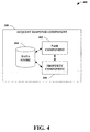
- Fig. 4 illustrates a
system 400 that facilitates interacting with a device to provide uniform techniques for communication and management. Therequest response component 308 can include apair component 402 that provides message exchange pairs that allow a device (not shown) and a server (not shown) to communicate. For example, the message exchanges can be defined as request response pairs that are asynchronous. Moreover, the message exchange is matched (e.g., paired) utilizing identification. The identification can be, for instance, a message identification that is unique to a particular corresponding pair. It is to be appreciated that thepair component 402 can support vendor specific commands (e.g., message exchange pairs, request response pairs, etc.). In addition, a command/routine (e.g., "SendMessage()"discussed infra) can be utilized to send requests to the device. - The
pair component 402 can utilize adata store 404 wherein the message exchange pairs can be stored. It is to be appreciated thedata store 404 can be an in-memory database within the DSPI (not shown) and/or on a remote server. Thedata store 404 can be employed to retain request response pairs that are supported by the DSPI component (not shown). Furthermore, thedata store 404 can be, for example, either volatile memory or nonvolatile memory, or can include both volatile and nonvolatile memory. By way of illustration, and not limitation, nonvolatile memory can include read only memory (ROM), programmable ROM (PROM), electrically programmable ROM (EPROM), electrically erasable programmable ROM (EEPROM), or flash memory. Volatile memory can include random access memory (RAM), which acts as external cache memory. By way of illustration and not limitation, RAM is available in many forms such as static RAM (SRAM), dynamic RAM (DRAM), synchronous DRAM (SDRAM), double data rate SDRAM (DDR SDRAM), enhanced SDRAM (ESDRAM), Synchlink DRAM (SLDRAM), Rambus direct RAM (RDRAM), direct Rambus dynamic RAM (DRDRAM), and Rambus dynamic RAM (RDRAM). Thedata store 404 of the subject systems and methods is intended to comprise, without being limited to, these and any other suitable types of memory. - The
pair component 402 supports a plurality of message exchange pairs. For instance, the following table, Table 1, illustrates a sample of suitable request response pairs (and a description) which can be utilized to communicate between a device and a server:Table 1 Command Response Description Writeld (string id, string passCode) Status Code and/or Error Writes ID to a tag. Id- Tag Id to write as a hex encoded string. passCode - optional password as a hex encoded string. If Id is null, it is equivalent to a writePassCode command, GetTagData (string id) User Data as provider specific string Reads a particular tag's (user) data given by Tag Id. All user data present on the tag is returned without any fine grained access. WriteTagData(string id, string data) Status Code and/or Error Writes User data to a particular tag given by Tag Id. Data string is in provider specified encoding. GetTagIds() List of Strings Reads all the tags and data available at the time of call and returns as a collection. It is a real time call which returns all the tags accessible by the device at that instant of time from one or more antennas. GetTagList() Tag List List of ID/Source read entries in the tag list. ClearTagList() Status Code and/or Error Clears Tag list. GetTagMetaData(string id) Tag Details Reads a particular tag's details (type, manufacture number, blocks, etc. ) given by Tag Id. LockTag(string id, string lockCode) Status Code and/or Error Locks a particular tag. lockCode is needed if it was set earlier. Kill (string id, string killCode) Status Code and/or Error Kills a tag. killCode is needed if it was set earlier. AddReadFilter (string bitMask, bool incExc) Status Code and/or Error Adds a simple bit mask filter to the device. RemoveReadFilter(string bitMask, bool incExc) Status Code and/or Error Removes the specified filter from the device ClearReadFilters() Status Code and/or Error Clears all the filters in the device. Reboot() Status Code and/or Error Reboot the device. Any connection to the device is lost and is not re-established. Writeld (string id, string passCode) Status Code and/or Error Writes ID to a tag. Id - Tag Id to write as a hex encoded string. passCode - optional password as a hex encoded string. If Id is null, it is equivalent to a writePassCode command.
Furthermore, thepair component 402 can provide a reply and/or a notification (e.g., received through "CmdResponseEvent" and "NotificationEvent" respectively). For instance, the notification event "ReadTagEvent" can be utilized in event mode and sent by the device to report a tag read/detect event. - The
request response component 308 can further include aproperty component 406 that can provide property pairs defined by the DSPI component (not shown). The property pairs can, for example, have substantially similar behavior to the message exchange pairs. In particular, the properties can be "get" or "set," which do not throw exceptions. It is to be appreciated the properties can be manipulated by a common mechanism (e.g., requests sent via SendMessage() method, discussed infra). It is to be appreciated that standard properties can be defined by the DSPI component (not shown), while the specific provider can define other properties. The provider(s) can support a property called REQUEST-TIMEOUT (e.g., in milliseconds) for a time-out request. It is to be appreciated that theproperty component 406 can utilize thedata store 404 to store the properties. - The
property component 406 supports a plurality of property pairs. For instance, the following table, Table 2, illustrates various property pairs (and a description) which can be utilized to communicate between a device and a server:Table 2 Command Response Description GetProperty(string propertyGroupName, string propertyName) Property object. NULL if no such property. Get the specified property. SetProperty(Property property) Status Code and/or Error Set the property. ApplyPropertyProfile(Property[] propertyProfile) Status Code and/or Error A plurality of properties can be applied at the same time using this method. Here's a scenario where such functionality will be useful: A set of properties need to be set for optimal performance of the device. All these can be specified as a profile in the device configuration. They can be applied at once by the server. GetProperty(string propertyGroupName, string propertyName) Property object. NULL if no such property. Get the specified property. SetProperty(Property property) Status Code and/or Error Set the property. - Furthermore, the
property component 406 supports a plurality of standard properties. For instance, the following table, Table 3, illustrates a standard property, specifically whether the property is read and/or write and a description:Table 3 Property Read/ Write Mandatory Description REQLTEST_TIMEOUT R/W Yes In milliseconds, timeout period for request messages. Provider sends a TIMEOUT response after this period has expired. - The
request response component 308 can utilize program code in order to utilize message exchange between a device and a server. The program code can be a markup language such as, but is not limited to, an extensible markup language (XML), a hypertext markup language (HTML), a standard generalized markup language (SGML), and an extensible hypertext markup language (XHTML). For example, a markup language can be utilized to provide a syntax for request, response, and notifications. It is to be appreciated that the request, notification, etc. can be represented as programmed objects in the DSPI component (not shown) to provide strong typing. - Fig. 5 illustrates a
system 500 that facilitates interacting with a device to provide uniform techniques for communication and management. Thedevice interface component 310 can include acommunication component 502 that facilitates defining a message layer and a transport layer. Moreover, thedevice interface component 310 further contains techniques for messaging and connection management. It is to be appreciated that thecommunication component 502 can contain at least one send channel and at least one receive channel to implement the message layer and the transport layer. - For instance, the
communication component 502 can include asend channel 504. The send channel can utilize "SendMessage()" in order to send information. In addition, thecommunication component 502 can have a first receivechannel 506 and a second receivechannel 508. The first receivechannel 506 can utilize "CmdResponseEvent" for responses (e.g., for request), while the second receivechannel 508 can utilize "NotificationEvent" for notifications. The response event can be for synchronous request-response commands, while the notifications can be for asynchronous, wherein notifications can be a tag list event, a reader management event, etc. It is to be appreciated that thedevice interface component 310 can also utilize a "ProviderException." The "ProviderException" is the top level exception for all the provider related exceptions. Any inner exception can be passed inside this exception. For example, the following code can define a ProviderException Class:
- The
communication component 502 can send messages to the device. The following code is an example of implementing "SendMessage()" to send a message: - void SendMessage (ICommand command);
- event ResponseEventHandler CmdResponseEvent;
- event ResponseEventHandler NotificationEvent;
- The code below can be implemented by the
device interface component 310 in order to open the message layer for communication. It is to be appreciated the standard ML (SML) message requests are sent utilizing the following code:

"DeviceInformation Devicelnformation {get}" provides device information relating to this device instance. It contains all information about this device. The device information class is provided at the time of discovery in the discovery event and from thedevice interface component 310. For example, the device information class can be defined as follows:
"void SendMessage (ICommand command);" is the command utilized to send all messages in the device layer. The following exceptions can be thrown:
ConnectionDownException (e.g., device is either not connected or connection went down); SendFailedException (e.g., connection to the device exists, but sending message to the device failed); System.ArgumentException (e.g., when the message parameter is invalid); etc. The function "event ResponseEventHandler CmdResponseEvent;" is an event that is generated whenever a response to a request comes. "event NotificationEventHandler NotificationEvent;" is an event that is generated whenever an asynchronous notification event is received from the device.
Furthermore, the following code can be utilized in handling exceptions relating to the communications:

It is to be appreciated that the above code can contain the techniques for properties and/or management. Additionally, the code below can create classes related to the exceptions as follows:
- The
device interface component 310 can also manage the connection maintained with a device. It is to be appreciated that the management of such connection can be for a plurality of devices associated to a provider. The connection to the device is maintained utilizing various functions (discussed infra). It is to be appreciated that the provider maintains the connection to the device until such connection is closed using the function "Close()." The connection management can be employed by utilizing the following code:
"bool SetupConnection();" sets up a connection to the device (e.g., abstracted by this Devicelnterface instance). This method can utilize the following exception:
ConnectionFailedException (e.g., connecting to the device failed). "void Close();" can remove states related to the device from the driver and/or close the connection. "bool IsConnectionAlive();" returns true if connection to the device (e.g., abstracted by this Devicelnterface instance) exists. "HashTable GetSources();" returns all the sources (e.g., antenna) at the device as name versus status (e.g., true if the source is connected and active). - Fig. 6 illustrates a
system 600 that facilitates interacting with a device to provide uniform techniques for communication and management. The devicediscovery interface component 312 can include an informcomponent 602 that informs the DSPI component (not shown) of a new device that is detected. The informcomponent 602 is extremely efficient such that one component is instantiated per provider so that the devices can be handled. It is to be appreciated that since the server may not have control over resources, the provider implements the devicediscovery interface component 312. Yet, the provider may implement such a devicediscovery interface component 312 and is not so limited. For example, the number of threads created can depend on the number of devices of a particular type. Moreover, if the discovery thread(s) encounter an error during execution, the provider can handle such error(s) in order to allow the threads to run. Moreover, the devicediscovery interface component 312 can define the device discovery mechanism by utilizing an interface such as, but is not limited to, DeviceListenerInterface. - The inform
component 602 can provide discovery of a newly detected device by utilizing the following code: The discovery start and stop can throw the exception: "public class DiscoveryException : ApplicationException {...}." In particular, the "DiscoveryEventHandler" is a callback handler for all discovery events (e.g., provider sends device discovery event to the host utilizing this event); "StartDiscovery" is the function to start the discovery of device; and "StopDiscovery" is the function to stop discovering new devices. Additionally, the above code utilizes device information object which includes information relating to the discovered RFID device.
- The device
discovery interface component 312 further includes aconnection component 604 that facilitates connecting to a device. For example, theconnection component 604 can utilize an XML string, such as "deviceIdXml", that encapsulates the information and/or data required to connect to the device. A schema can be employed by theconnection component 604 that includes the following: a unique ID of a device, a provider name, a transport name, a standard transports, etc. For instance, the following schema can be utilized by the connection component 604:
The device information class provides information about the RFID device. This class is provided by the provider at the time of discovery in the discovery event and from thedevice interface component 310 in Fig. 3. - Furthermore, a connection information class can be used for connection to an RFID device. For devices which support discovery, this object can be obtained from Devicelnformation object from the DiscoveryEvent. For devices that do not support discovery, this object can be manually filled before calling GetDevice() on ServiceProviderInterface object. The connection information class can be defined as follows:

- Fig. 7 illustrates a
system 700 that facilitates interacting with a device to provide uniform techniques for communication and management. The SPI providers can be, for instance, assemblies that provide a multitude of advantages (e.g., .NET assemblies). It is to be appreciated theSPI container component 314 maintains driver state at a minimum. In other words, the amount of devices discovered and/or connected is unimportant to theSPI component 314. - The
SPI container component 314 can include aservice provider component 702 that can implement a service provider interface. The service provider interface is the entry point for the DSPI component (not shown). A DSPI implementer requires the interface in order to utilize an entry point. It is to be appreciated that methods in the interface can utilize the ProviderException. For example, the following code can be employed:
It is to be appreciated that a driver class supports the interface created above. Moreover, the "ProviderException" defined infra can be called. "ProviderInformation Providerlnformation {get;};" provides information about the DSPI provider, which can be utilized for information purposes by the DSPI host(s). A provider information class can be utilized to provide such information. For example, the following can be utilized to define the provider information class:
"Encoding UserDataEncoding {get;};" provides the encoding expected by the provider for user data (e.g., ASCII, Hex, ...). The function "void Init(string hosted, string initXml);" is the constructor of the provider. Host initializes the DSPI provider utilizing this method. "hostId" can be used for informational purposes by the provider, while "initXml" is provider specific XML (e.g., whose schema is specific to the provider), which can be utilized by the provider to initialize itself. The function "void Shutdown()" can be used when devices are still connected, wherein the server is responsible for closing such connections. The function stops the discovery thread, cleans up state conditions, and/or resets the system. Thus, it is the destructor of the provider, and shuts down the provider. "DeviceListenerInterface GetDeviceListener()" returns a reference to an object that supports, as cited in the code, Devicelnterface Listener interface (e.g., device interface component 310) that is utilized for discovery. Moreover, "DeviceInterface GetDevice(Connectionlnformation deviceConnectionInfo" implements ServiceProviderInterface interface to act as the factory for Devicelnterface interface. DeviceInterface interface abstracts an RFID device to which a host can communicate. It is also to be appreciated that the code "bool IsValidDevice(DeviceInformation deviceInfo);" provides a return of true if the device information represents a valid device supported by this device and is available for connection or connected already. "string[] GetPropertyGroupNames();" returns names of property groups supported by this provider. A global property group with the name "String.Empty" is not returned by this method. The function "Hashtable GetpropertyMetadata(string propertyGroupName, string propertyName);" returns meta data about the properties as group name versus property meta data map. The return value can be defined by the following table:Property Name - NULL Property Name - NON NULL Property Group Name - NULL Meta data for all global properties - as empty string versus property meta data, Meta data for named global property - as empty string versus property meta data; if this is not a global property return NULL Property Group Name - NON -NULL Meta data for all properties in this group as group name versus property meta data. Meta data for named property in named group- as group name versus property meta data; if this is not a property belonging to this group, return NULL
The function "PropertyProfile GetIdealReaderPropertyProfile();" returns the optimal property profile for the RFID device which is in Reader role (e.g., which is in tag notification mode) for this provider. It contains the set of properties which when applied, results in the reader operating optimally. "PropertyProfile GetIdealWriterPropertyProfile();" returns the optimal property for the RFID device which is in Writer role (e.g., synchronous commands mode) for this provider. It contains the set of properties which when applied, results in the writer operating optimally. - The
SPI container component 314 can include adriver component 704 to facilitate registering at least one driver with a server. Thedriver component 704 provides the driver registration with the server in order to allow verified and authentic drivers. For instance, the driver registration can utilize digital signatures that enable secured and/or authentic drivers that ensure compatibility and functionality. For example, an IDriverManager interface can be implemented with the following code: The IDriverNianager interface can be supported by, for instance, an RFID accelerator. Moreover, it is to be appreciated that a client can utilize a .NET platform to remotely connect and manage drivers. As stated supra, .NET platform provides a variety of advantages relating to the use of drivers and versatility. The code "string LoadDriver (AssemblyQualifiedNamespace);" can be implemented by the
driver component 704. The path can be of an assembly located on a local machine, wherein the following exceptions can be thrown: assembly not found; version of driver in assembly not supported by the server; and identifier of assembly not unique (e.g., across the loaded drivers), wherein the identifier identifies a driver upon loading. It is to be appreciated that the "providerInstanceId" is returned upon the correct load of a driver. In addition, thedriver component 704 can utilize the function "void UnloadDriver (string providerInstanceId);" that provides the removal of the driver from the server configuration. The driver corresponding to identifier not found is an exception that can be thrown in relation to the function. -
Driver component 704 can implement the code, "string ListLoadedDrivers();" that facilitates managing drivers. It is to be appreciated that thedriver component 704 can provide management, wherein the string returned from the function "string ListLoadedDrivers();" can be an XML string with the following format: The above code can create a complex type with the reference name, "Drivers." Furthermore, the code contains a driver name (e.g., providerlnstanceld), a driver assembly name, and a driver version.
- Fig. 8 illustrates a
system 800 that facilitates utilizing a device service provider interface (DSPI)component 802 to provide uniform communication and management for a plurality of devices and associated providers.Providers 804 can include a plurality of providers such as an EPC-Gcompliant provider 808, a firstproprietary provider 810, and a secondproprietary provider 812. It is to be appreciated that theproviders 804 enable service to an associated device. For instance, the EPC-Gcompliant provider 808 can be associated to an EPC-Global device 814, the firstproprietary provider 810 can be associated to afirst legacy device 816, and the secondproprietary provider 812 can be associated to asecond legacy device 818. It is to be appreciated that aDSPI component 802 interacts through one of the existingproviders 804 for the associated device (e.g., the EPC-Global device 814, thefirst legacy device 816, and the second legacy device 818). TheDSPI component 802 provides a uniform manner in which theproviders 804 provide services to middleware products as each device supports a different set of commands. In other words, theDSPI component 802 defines interfaces for device vendors (e.g., and associated devices) to uniformly provide services to anRFID server 806. - It is to be appreciated that the
DSPI component 802 can support in the message layer commands specific to at least one of theproviders 804. The provider specific commands can be sent utilizing the following command object:

The object above contains the provider specific command as a string. Additional parameters can be passed in the ParameterCollection. Reply to the command is sent as a reply string and any additional data is put in the data object. It is to be further appreciated that a provider specific notification can be sent utilizing the following event object:
This object contains an event id, vendor id, provider specific event name, and any provider specific data for the event. - In accordance with one aspect of the subject invention, the DSPI provider can implement a tag list functionality. A tag list stores the tags detected by the device (e.g., up to a buffer limit). The tag list eliminates duplicates utilizing DUPLICATE_ELIMINATION_TIME and stores them in the tag list. The tag list is utilized to store the detected tags at the device so that a host does not lose tags even if it is not connected to the provider. Tag list contains a collection of Tag entries, which is defined below:
 Tag stores a tag Id, optional tag data, optional tag type, optional time, and optional source. Source is stored as simple provider specific string (e.g., Antennal). It is to be appreciated that the source names can be, but are not limited to, Antenna1, Antenna2, and so on and so forth.
- In accordance with another aspect of the subject invention, a bitmask filter can be applied to the tag ids of detected tags. Filter patterns can be implemented such as, for instance, utilizing zeros, ones, and x's, wherein an x represents a do not care. A filter is applied to the tag id of matching length only. In one example, filters are applied only to notifications. Synchronous commands do not apply these filters. A BitMaskReadFilter can be employed utilizing the following:

- In accordance with yet another aspect of the subject invention, at least one of the
providers 804 can provide a set of tag commands which support a pass code. If a user sets the pass code utilizing the "WriteID" command, it will be applicable to all these secure operations. If the user had no pas code, all these will become normal commands. Pass codes will be specific to a tag. - Fig. 9 illustrates a
system 900 that facilitates utilizing a device service provider interface (DSPI)component 902 to provide uniform communication and/or management for a device. TheDSPI component 902 facilitates communicating between anRFID server 906 and anRFID device 904 by providing uniform techniques for communication and management. For instance, a provider (not shown) associated to at least oneRFID device 904 can implement theDSPI component 902. The provider can be a processor independent platform assembly that implements the interface(s) defined by theDSPI component 902. - The
DSPI component 902 can utilize ahistory component 908 that provides a log of activity based at least upon theDSPI component 902, theRFID server 906, and/or theRFID device 904. The history component can track and/or log information such as, for instance, provider lists, devices associated to providers, connection history, connection data, signal data, authentication data, etc. Furthermore, it is to be appreciated that the activity log created by thehistory component 908 can be real-time data stream and/or stored data. Thehistory component 908 can utilize adata store 914 to store such log activity and/or historic data.Such data store 914 is described in detail infra. - The
DSPI component 902 can interact with asecurity component 910 to provide additional security to thesystem 900. Thesecurity component 910 can allow authentication (e.g., login and/or password), verification (e.g., verifying such login and password), secured connection (e.g., based at least upon verification), security levels (e.g., based on a user name and/or password), encryption, etc. For example, thesecurity component 910 can provide a secure connection, wherein information can be exchanged that allows providers to interact with and/or utilize interfaces defined by theDSPI component 902. Furthermore, the authentication and/or verification of thesystem 900 can increase the confidence of users regarding the drivers provided. - In accordance with one aspect of the subject invention, the
DSPI component 902 can utilize alearn component 912 to facilitate establishing communication between theRFID server 906 and theRFID device 904. Thelearn component 912 can utilize machine learning (e.g., artificial intelligence) techniques in order to determine, for example, provider activity/behavior, device activity/behavior, security trends, etc. Thelearn component 912 can analyze the information associated to thehistory component 908 such as, for instance, historic data and/or activity logs to determine whether a provider can implement an interface defined by theDSPI component 902. Furthermore, in determining whether a particular device is to be connected and/or serviced, thelearn component 912 can analyze characteristics and/or behavior patterns determined based at least in part upon artificial intelligence techniques. - It is to be appreciated that the
history component 908, thesecurity component 910, and/or thelearn component 912 can utilize thedata store 914 in order to store data. Thedata store 914 can be located within theDSPI component 902 and/or on a remote server. Furthermore, thedata store 914 can be, for example, either volatile memory or nonvolatile memory, or can include both volatile and nonvolatile memory. By way of illustration, and not limitation, nonvolatile memory can include read only memory (ROM), programmable ROM (PROM), electrically programmable ROM (EPROM), electrically erasable programmable ROM (EEPROM), or flash memory. Volatile memory can include random access memory (RAM), which acts as external cache memory. By way of illustration and not limitation, RAM is available in many forms such as static RAM (SRAM), dynamic RAM (DRAM), synchronous DRAM (SDRAM), double data rate SDRAM (DDR SDRAM), enhanced SDRAM (ESDRAM), Synchlink DRAM (SLDRAM), Rambus direct RAM (RDRAM), direct Rambus dynamic RAM (DRDRAM), and Rambus dynamic RAM (RDRAM). Thedata store 914 of the subject systems and methods is intended to comprise, without being limited to, these and any other suitable types of memory. - Figs. 10-12 illustrate methodologies in accordance with the subject invention. For simplicity of explanation, the methodologies are depicted and described as a series of acts. It is to be understood and appreciated that the subject invention is not limited by the acts illustrated and/or by the order of acts, for example acts can occur in various orders and/or concurrently, and with other acts not presented and described herein. Furthermore, not all illustrated acts may be required to implement the methodologies in accordance with the subject invention. In addition, those skilled in the art will understand and appreciate that the methodologies could alternatively be represented as a series of interrelated states via a state diagram or events.
- Fig. 10 illustrates a
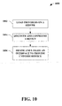
methodology 1000 that facilitates communicating with a device by utilizing a uniform technique for interaction. At 1002, providers can be loaded on a server. In particular, an SPI container can load the provider(s) onto an RFID server. Upon loading the provider(s) onto a server, the version of the SPI can be verified to be compatible with such server. Furthermore, the driver(s) can be registered with the RFID server in order to provide compatible driver(s) (e.g., digital verification). - At 1004, a device is discovered and configured. The discovery is efficient such that one component is instantiated per a provider and the devices can be utilized. Furthermore, the provider handles the discovery thread errors during the discovery process. After discovery of a device, a string can provide information required to connect and/or configure the device. For instance, the string can be in markup language format (e.g., an extensible markup language (XML), a hypertext markup language (HTML), a standard generalized markup language (SGML), and an extensible hypertext markup language (XHTML), ...) having information such as, but is not limited to, a unique id of the device, a provider name, a transport name, etc.
- Next at 1006, an interface can be defined and utilized in order to provide a uniform service to the device. Once a provider is loaded on the RFID server, and a device is discovered and/or configured, the interface(s) can be utilized by a provider in order to communicate with uniform techniques. The defined interfaces can provide discovery and configuration for new devices; and further communication can connection management for all devices (e.g., new and established). By utilizing uniform technique(s), normalization is provided across a multitude of standards.
- Fig. 11 illustrates a
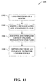
methodology 1100 that facilitates communicating with a device. At 1102, a provider is loaded onto an RFID server. Once authenticated, the provider is loaded, wherein a plurality of services can be provided uniformly by utilizing at least one interface. At 1104, a message layer and/or a transport layer are defined. Messaging and/or connection managing is provided within the message layer and/or the transport layer. For instance, a send channel can utilize "SendMessage()" to send message exchanges. Additionally, a first receive channel for responses can implement "CmdResponseEvent," while a second receive channel for notifications can utilize "NotificationEvent." The connection management can be provided utilizing an XML string. It is to be appreciated the provider can maintain a connection to a device until the connection is closed with the function "Close()." - At 1106, device(s) can be discovered and configured by utilizing the message layer and/or transport layer. The discovery and configuration of the device(s) is done with message exchange pairs. The message exchange pairs are exchanged between the server and the device. It is to be appreciated that the message exchange pairs are asynchronous and can be matched utilizing a message identification. As stated supra, the "SendMessage()" can be used to send requests to a device, while replies and notifications are received with "CmdResponseEvent" and "NotificationEvent" respectively. Furthermore, the message exchange pairs can utilize properties to configure the device(s). It is to be appreciated that standard properties can also be defined and implemented by the configuration and/or discovery process.
- Next at 1108, an interface is defined and utilized to provide uniform service via the RFID server to the discovered and configured devices. Message exchange pairs can provide uniform techniques to communicate with existing and/or newly detected devices. It is to be appreciated that numerous interfaces can be defined for discovery, configuration, communication, and connection management. In general, the
method 1100 can provide an abstraction layer to communicate with and to manage devices uniformly. - Fig. 12 illustrates a
methodology 1200 that provides a uniform technique to communicate and/or manage a device. At 1202, RFID providers are loaded onto an RFID server in order to provide services. It is to be appreciated that new providers are detected and loaded accordingly upon authentication and/or verification. At 1204, a message layer and a transport layer are defined providing communication capabilities from a device service provider interface (DSPI) component and an RFID device. At 1206, a determination is made whether a new device is detected. If a new device is detected, the process proceeds to 1208, where the device is connected, authenticated, and configured accordingly. If a new device is not detected, the process continues to 1210, where interfaces can be defined and utilized to provide uniform services to the detected (e.g., discovered, verified, and/or authenticated) RFID devices. - It is to be appreciated that the
process 1200 provides a continuous polling and/or a period determination on whether a new provider and/or new associated devices are present within the RFID server. In other words, while providing the uniform service to the detected devices, the process can proceed to 1202 upon the detection of a new provider, wherein the provider can be loaded and associated devices can be discovered, connected, and authenticated. Furthermore, it is to be appreciated that a new device can be established on a pre-existing provider. Thus, the process can discover and configure such a new device accordingly. A substantially continuous polling and/or a periodic check can employ the determination of new devices and/or providers. - In order to provide additional context for implementing various aspects of the subject invention, Figs. 13-14 and the following discussion is intended to provide a brief, general description of a suitable computing environment in which the various aspects of the subject invention may be implemented. While the invention has been described above in the general context of computer-executable instructions of a computer program that runs on a local computer and/or remote computer, those skilled in the art will recognize that the invention also may be implemented in combination with other program modules. Generally, program modules include routines, programs, components, data structures, etc., that perform particular tasks and/or implement particular abstract data types.
- Moreover, those skilled in the art will appreciate that the inventive methods may be practiced with other computer system configurations, including single-processor or multi-processor computer systems, minicomputers, mainframe computers, as well as personal computers, hand-held computing devices, microprocessor-based and/or programmable consumer electronics, and the like, each of which may operatively communicate with one or more associated devices. The illustrated aspects of the invention may also be practiced in distributed computing environments where certain tasks are performed by remote processing devices that are linked through a communications network. However, some, if not all, aspects of the invention may be practiced on stand-alone computers. In a distributed computing environment, program modules may be located in local and/or remote memory storage devices.
- Fig. 13 is a schematic block diagram of a sample-
computing environment 1300 with which the subject invention can interact. Thesystem 1300 includes one or more client(s) 1310. The client(s) 1310 can be hardware and/or software (e.g., threads, processes, computing devices). Thesystem 1300 also includes one or more server(s) 1320. The server(s) 1320 can be hardware and/or software (e.g., threads, processes, computing devices). Theservers 1320 can house threads to perform transformations by employing the subject invention, for example. - One possible communication between a
client 1310 and aserver 1320 can be in the form of a data packet adapted to be transmitted between two or more computer processes. Thesystem 1300 includes acommunication framework 1340 that can be employed to facilitate communications between the client(s) 1310 and the server(s) 1320. The client(s) 1310 are operably connected to one or more client data store(s) 1350 that can be employed to store information local to the client(s) 1310. Similarly, the server(s) 1320 are operably connected to one or more server data store(s) 1330 that can be employed to store information local to theservers 1340. - With reference to Fig. 14, an
exemplary environment 1400 for implementing various aspects of the invention includes acomputer 1412. Thecomputer 1412 includes aprocessing unit 1414, asystem memory 1416, and asystem bus 1418. Thesystem bus 1418 couples system components including, but is not limited to, thesystem memory 1416 to theprocessing unit 1414. Theprocessing unit 1414 can be any of various available processors. Dual microprocessors and other multiprocessor architectures also can be employed as theprocessing unit 1414. - The
system bus 1418 can be any of several types of bus structure(s) including the memory bus or memory controller, a peripheral bus or external bus, and/or a local bus using any variety of available bus architectures including, but are not limited to, Industrial Standard Architecture (ISA), Micro-Channel Architecture (MSA), Extended ISA (EISA), Intelligent Drive Electronics (IDE), VESA Local Bus (VLB), Peripheral Component Interconnect (PCI), Card Bus, Universal Serial Bus (USB), Advanced Graphics Port (AGP), Personal Computer Memory Card International Association bus (PCMCIA), Firewire (IEEE 1394), and Small Computer Systems Interface (SCSI). - The
system memory 1416 includesvolatile memory 1420 andnonvolatile memory 1422. The basic input/output system (BIOS), containing the basic routines to transfer information between elements within thecomputer 1412, such as during start-up, is stored innonvolatile memory 1422. By way of illustration, and not limitation,nonvolatile memory 1422 can include read only memory (ROM), programmable ROM (PROM), electrically programmable ROM (EPROM), electrically erasable programmable ROM (EEPROM), or flash memory.Volatile memory 1420 includes random access memory (RAM), which acts as external cache memory. By way of illustration and not limitation, RAM is available in many forms such as static RAM (SRAM), dynamic RAM (DRAM), synchronous DRAM (SDRAM), double data rate SDRAM (DDR SDRAM), enhanced SDRAM (ESDRAM), Synchlink DRAM (SLDRAM), Rambus direct RAM (RDRAM), direct Rambus dynamic RAM (DRDRAM), and Rambus dynamic RAM (RDRAM). -
Computer 1412 also includes removable/non-removable, volatile/non-volatile computer storage media. Fig. 14 illustrates, for example adisk storage 1424.Disk storage 1424 includes, but is not limited to, devices like a magnetic disk drive, floppy disk drive, tape drive, Jaz drive, Zip drive, LS-100 drive, flash memory card, or memory stick. In addition,disk storage 1424 can include storage media separately or in combination with other storage media including, but is not limited to, an optical disk drive such as a compact disk ROM device (CD-ROM), CD recordable drive (CD-R Drive), CD rewritable drive (CD-RW Drive) or a digital versatile disk ROM drive (DVD-ROM). To facilitate connection of thedisk storage devices 1424 to thesystem bus 1418, a removable or non-removable interface is typically used such asinterface 1426. - It is to be appreciated that Fig. 14 describes software that acts as an intermediary between users and the basic computer resources described in the
suitable operating environment 1400. Such software includes anoperating system 1428.Operating system 1428, which can be stored ondisk storage 1424, acts to control and allocate resources of thecomputer system 1412.System applications 1430 take advantage of the management of resources byoperating system 1428 throughprogram modules 1432 andprogram data 1434 stored either insystem memory 1416 or ondisk storage 1424. It is to be appreciated that the subject invention can be implemented with various operating systems or combinations of operating systems. - A user enters commands or information into the
computer 1412 through input device(s) 1436.Input devices 1436 include, but are not limited to, a pointing device such as a mouse, trackball, stylus, touch pad, keyboard, microphone, joystick, game pad, satellite dish, scanner, TV tuner card, digital camera, digital video camera, web camera, and the like. These and other input devices connect to theprocessing unit 1414 through thesystem bus 1418 via interface port(s) 1438. Interface port(s) 1438 include, for example, a serial port, a parallel port, a game port, and a universal serial bus (USB). Output device(s) 1440 use some of the same type of ports as input device(s) 1436. Thus, for example, a USB port may be used to provide input tocomputer 1412, and to output information fromcomputer 1412 to anoutput device 1440.Output adapter 1442 is provided to illustrate that there are someoutput devices 1440 like monitors, speakers, and printers, amongother output devices 1440, which require special adapters. Theoutput adapters 1442 include, by way of illustration and not limitation, video and sound cards that provide a means of connection between theoutput device 1440 and thesystem bus 1418. It should be noted that other devices and/or systems of devices provide both input and output capabilities such as remote computer(s) 1444. -
Computer 1412 can operate in a networked environment using logical connections to one or more remote computers, such as remote computer(s) 1444. The remote computer(s) 1444 can be a personal computer, a server, a router, a network PC, a workstation, a microprocessor based appliance, a peer device or other common network node and the like, and typically includes many or all of the elements described relative tocomputer 1412. For purposes of brevity, only amemory storage device 1446 is illustrated with remote computer(s) 1444. Remote computer(s) 1444 is logically connected tocomputer 1412 through anetwork interface 1448 and then physically connected viacommunication connection 1450.Network interface 1448 encompasses wire and/or wireless communication networks such as local-area networks (LAN) and wide-area networks (WAN). LAN technologies include Fiber Distributed Data Interface (FDDI), Copper Distributed Data Interface (CDDI), Ethernet, Token Ring and the like. WAN technologies include, but are not limited to, point-to-point links, circuit switching networks like Integrated Services Digital Networks (ISDN) and variations thereon, packet switching networks, and Digital Subscriber Lines (DSL). - Communication connection(s) 1450 refers to the hardware/software employed to connect the
network interface 1448 to thebus 1418. Whilecommunication connection 1450 is shown for illustrative clarity insidecomputer 1412, it can also be external tocomputer 1412. The hardware/software necessary for connection to thenetwork interface 1448 includes, for exemplary purposes only, internal and external technologies such as, modems including regular telephone grade modems, cable modems and DSL modems, ISDN adapters, and Ethernet cards. - What has been described above includes examples of the subject invention. It is, of course, not possible to describe every conceivable combination of components or methodologies for purposes of describing the subject invention, but one of ordinary skill in the art may recognize that many further combinations and permutations of the subject invention are possible. Accordingly, the subject invention is intended to embrace all such alterations, modifications, and variations that fall within the spirit and scope of the appended claims.
- In particular and in regard to the various functions performed by the above described components, devices, circuits, systems and the like, the terms (including a reference to a "means") used to describe such components are intended to correspond, unless otherwise indicated, to any component which performs the specified function of the described component (e.g., a functional equivalent), even though not structurally equivalent to the disclosed structure, which performs the function in the herein illustrated exemplary aspects of the invention. In this regard, it will also be recognized that the invention includes a system as well as a computer-readable medium having computer-executable instructions for performing the acts and/or events of the various methods of the invention.
- In addition, while a particular feature of the invention may have been disclosed with respect to only one of several implementations, such feature may be combined with one or more other features of the other implementations as may be desired and advantageous for any given or particular application. Furthermore, to the extent that the terms "includes," and "including" and variants thereof are used in either the detailed description or the claims, these terms are intended to be inclusive in a manner similar to the term "comprising."
The
System. ArgumentException (e.g., when a message parameter is invalid), etc. Moreover, the
The code above is an event that is generated when a response to a request is received. It is to be appreciated that the above code can be given by a device when a response to a command is received. Additionally, the
The event above is generated when a notification event is received by the device. Moreover, the above code can be given by a device when an asynchronous event is received. It is to be appreciated the
Claims (20)
- A system that facilitates interacting with a device, comprising:a component that receives a protocol translation that relates to a device; anda device service provider interface (DSPI) component that defines an interface to uniformly communicate to the device and expose functionality of the device regardless of a device vendor and the protocol standard.
- The system of claim 1, the device can have at least one of the following: an associated provider that implements the interface to expose functionality; the device vendor as a third-party vendor to utilize the DSPI component.
- The system of claim 2, the associated provider utilizes a device command, which abstracts a device specific detail and is a processor independent platform assembly.
- The system of claim 1, further comprising a request response component that defines a message exchange that is a command and a response object, wherein the command and the response are asynchronous and matched utilizing a message ID.
- The system of claim 4, the message exchange is a request response pair being at least one of the following: a command; a property; and a notification.
- The system of claim 1, the device is at last one of the following: a radio frequency identification (RFID) device, a real-time sensor, a sensor, a device extensible to a web service, and a real-time event generation system.
- The system of claim 1, the DSPI component separates a logical event source and a physical event source, wherein there is one instantiation and such instantiation is utilized to work with the device regardless of at least one of the following: a location, a type, the device vender, the protocol standard.
- The system of claim 1, further comprising a device interface component that defines a layer, wherein the layer is one of: a message layer; and a transport layer.
- The system of claim 1, further comprising a device discovery interface component that defines an device discovery mechanism utilizing a markup language defined string encapsulating device connection data, wherein the device discovery mechanism instantiates one DSPI component per provider.
- The system of claim 1, further comprising an SPI container component that loads a DSPI provider, wherein the SPI container component provides one of the following: a compatible SPI version; a digital authentication of a driver; and a driver registration.
- The system of claim 1, the DSPI component utilizes a security component that provides one of the following: a secure connection; an authentication of a provider; and a verification of the device.
- A computer readable medium having stored thereon the components of the system of claim 1.
- A computer-implemented method that facilitates interacting with a device, comprising:receiving a protocol translation that relates to a device; anddefining an interface to uniformly communicate to the device and expose functionality of the device regardless of a device vendor and the protocol standard.
- The method of claim 13, further comprising:loading a provider into an RFID server;defining a message layer and a transport layer; anddiscovering and configuring the device.
- The method of claim 13, further comprising a message exchange pair that is asynchronous.
- The method of claim 15, the message exchange pair is one of the following: a request and a response; a request and a reply; a request and a notification; and a request and a property.
- The method of claim 13, further comprising separating a logical event source and a physical event source.
- The method of claim 13, further comprising extending the interface to at least one of a third party device vendor, a web service, and a real-time sensor device.
- A data packet that communicates between a receiver component and the interface, the data packet facilitates the method of claim 13.
- A computer implemented system that facilitates interacting with a radio frequency identification (RFID) device, comprising:means for receiving a protocol translation that relates to a device; andmeans for defining an interface to uniformly communicate to the device and expose functionality of the device regardless of a device vendor and the protocol standard
Applications Claiming Priority (3)
| Application Number | Priority Date | Filing Date | Title |
|---|---|---|---|
| US60628104P | 2004-09-01 | 2004-09-01 | |
| US60657704P | 2004-09-02 | 2004-09-02 | |
| US11/061,337 US7701341B2 (en) | 2004-09-01 | 2005-02-18 | Device service provider interface |
Publications (2)
| Publication Number | Publication Date |
|---|---|
| EP1632893A2 true EP1632893A2 (en) | 2006-03-08 |
| EP1632893A3 EP1632893A3 (en) | 2006-03-22 |
Family
ID=35502895
Family Applications (1)
| Application Number | Title | Priority Date | Filing Date |
|---|---|---|---|
| EP05107826A Withdrawn EP1632893A3 (en) | 2004-09-01 | 2005-08-26 | Device service provider interface |
Country Status (9)
| Country | Link |
|---|---|
| US (1) | US7701341B2 (en) |
| EP (1) | EP1632893A3 (en) |
| JP (1) | JP4974487B2 (en) |
| KR (1) | KR101183334B1 (en) |
| AU (1) | AU2005204231A1 (en) |
| BR (1) | BRPI0504756A (en) |
| CA (1) | CA2517860C (en) |
| MX (1) | MXPA05009275A (en) |
| TW (1) | TW200611169A (en) |
Cited By (11)
| Publication number | Priority date | Publication date | Assignee | Title |
|---|---|---|---|---|
| WO2007106283A1 (en) * | 2006-03-10 | 2007-09-20 | Microsoft Corporation | Rfid business process-decoupling of design and deployment time activities |
| WO2008002120A2 (en) * | 2006-06-30 | 2008-01-03 | Rfid De Mexico S.A. De C.V. | System and method for optimizing resources in a supply or production chain using rfid and artificial intelligence |
| US7378966B2 (en) | 2006-01-04 | 2008-05-27 | Microsoft Corporation | RFID device groups |
| US7382260B2 (en) | 2004-09-01 | 2008-06-03 | Microsoft Corporation | Hot swap and plug-and-play for RFID devices |
| US7533812B2 (en) | 2004-09-01 | 2009-05-19 | Microsoft Corporation | Reader application markup language schema |
| WO2009128695A1 (en) * | 2008-04-16 | 2009-10-22 | Rfid Mexico S.A. De C.V. | Rfid network system |
| US7675418B2 (en) | 2006-06-15 | 2010-03-09 | Microsoft Corporation | Synchronous command model for RFID-enabling applications |
| US7701341B2 (en) | 2004-09-01 | 2010-04-20 | Microsoft Corporation | Device service provider interface |
| US7868738B2 (en) | 2006-06-15 | 2011-01-11 | Microsoft Corporation | Device simulator framework for an RFID infrastructure |
| US7956724B2 (en) | 2006-06-15 | 2011-06-07 | Microsoft Corporation | Support for reliable end to end messaging of tags in an RFID infrastructure |
| US8098158B2 (en) | 2004-09-01 | 2012-01-17 | Microsoft Corporation | RFID server internals design |
Families Citing this family (62)
| Publication number | Priority date | Publication date | Assignee | Title |
|---|---|---|---|---|
| US7789308B2 (en) * | 2004-05-13 | 2010-09-07 | Cisco Technology, Inc. | Locating and provisioning devices in a network |
| US8113418B2 (en) * | 2004-05-13 | 2012-02-14 | Cisco Technology, Inc. | Virtual readers for scalable RFID infrastructures |
| US7422152B2 (en) * | 2004-05-13 | 2008-09-09 | Cisco Technology, Inc. | Methods and devices for providing scalable RFID networks |
| US8604910B2 (en) * | 2004-07-13 | 2013-12-10 | Cisco Technology, Inc. | Using syslog and SNMP for scalable monitoring of networked devices |
| US8217756B2 (en) * | 2004-09-01 | 2012-07-10 | Microsoft Corporation | Rule-based filtering and alerting |
| US7339476B2 (en) * | 2004-11-10 | 2008-03-04 | Rockwell Automation Technologies, Inc. | Systems and methods that integrate radio frequency identification (RFID) technology with industrial controllers |
| US7551081B2 (en) * | 2004-11-10 | 2009-06-23 | Rockwell Automation Technologies, Inc. | Systems and methods that integrate radio frequency identification (RFID) technology with agent-based control systems |
| US20060168112A1 (en) * | 2004-12-30 | 2006-07-27 | Jie Weng | Generic integration within an auto-id system |
| US7830256B2 (en) * | 2005-04-07 | 2010-11-09 | Microsoft Corporation | Method and system for setup of, and communication with, an RFID middleware server from an enterprise resource planning system server |
| US8131213B2 (en) * | 2005-06-15 | 2012-03-06 | Wfs Technologies Ltd. | Sea vessel tagging apparatus and system |
| US7953826B2 (en) * | 2005-07-14 | 2011-05-31 | Cisco Technology, Inc. | Provisioning and redundancy for RFID middleware servers |
| US7616117B2 (en) * | 2005-07-19 | 2009-11-10 | Rockwell Automation Technologies, Inc. | Reconciliation mechanism using RFID and sensors |
| US7388491B2 (en) | 2005-07-20 | 2008-06-17 | Rockwell Automation Technologies, Inc. | Mobile RFID reader with integrated location awareness for material tracking and management |
| US7764191B2 (en) | 2005-07-26 | 2010-07-27 | Rockwell Automation Technologies, Inc. | RFID tag data affecting automation controller with internal database |
| US7345585B2 (en) * | 2005-08-01 | 2008-03-18 | Cisco Technology, Inc. | Network based device for providing RFID middleware functionality |
| US8260948B2 (en) | 2005-08-10 | 2012-09-04 | Rockwell Automation Technologies, Inc. | Enhanced controller utilizing RFID technology |
| US7510110B2 (en) * | 2005-09-08 | 2009-03-31 | Rockwell Automation Technologies, Inc. | RFID architecture in an industrial controller environment |
| US7931197B2 (en) | 2005-09-20 | 2011-04-26 | Rockwell Automation Technologies, Inc. | RFID-based product manufacturing and lifecycle management |
| US7446662B1 (en) | 2005-09-26 | 2008-11-04 | Rockwell Automation Technologies, Inc. | Intelligent RFID tag for magnetic field mapping |
| US8025227B2 (en) | 2005-09-30 | 2011-09-27 | Rockwell Automation Technologies, Inc. | Access to distributed databases via pointer stored in RFID tag |
| US20070075832A1 (en) * | 2005-09-30 | 2007-04-05 | Rockwell Automation Technologies, Inc. | RFID reader with programmable I/O control |
| US8698603B2 (en) | 2005-11-15 | 2014-04-15 | Cisco Technology, Inc. | Methods and systems for automatic device provisioning in an RFID network using IP multicast |
| US8155142B2 (en) * | 2006-03-16 | 2012-04-10 | Exceptional Innovation Llc | Network based digital access point device |
| US7966083B2 (en) | 2006-03-16 | 2011-06-21 | Exceptional Innovation Llc | Automation control system having device scripting |
| US8725845B2 (en) | 2006-03-16 | 2014-05-13 | Exceptional Innovation Llc | Automation control system having a configuration tool |
| US8001219B2 (en) * | 2006-03-16 | 2011-08-16 | Exceptional Innovation, Llc | User control interface for convergence and automation system |
| US8209398B2 (en) * | 2006-03-16 | 2012-06-26 | Exceptional Innovation Llc | Internet protocol based media streaming solution |
| US7509402B2 (en) * | 2006-03-16 | 2009-03-24 | Exceptional Innovation, Llc | Automation control system having a configuration tool and two-way ethernet communication for web service messaging, discovery, description, and eventing that is controllable with a touch-screen display |
| US7496627B2 (en) * | 2006-03-16 | 2009-02-24 | Exceptional Innovation, Llc | Automation control system having digital logging |
| US8271881B2 (en) * | 2006-04-20 | 2012-09-18 | Exceptional Innovation, Llc | Touch screen for convergence and automation system |
| US7667968B2 (en) | 2006-05-19 | 2010-02-23 | Exceptional Innovation, Llc | Air-cooling system configuration for touch screen |
| US20080010535A1 (en) * | 2006-06-09 | 2008-01-10 | Microsoft Corporation | Automated and configurable system for tests to be picked up and executed |
| US8207822B2 (en) * | 2006-06-15 | 2012-06-26 | Microsoft Corporation | Support for batching of events, and shredding of batched events in the RFID infrastructure platform |
| US20080001711A1 (en) * | 2006-06-15 | 2008-01-03 | Microsoft Corporation | Reliability of execution for device provider implementations |
| WO2008073658A2 (en) * | 2006-11-09 | 2008-06-19 | Exceptional Innovation, Llc. | Portable device for convergence and automation solution |
| US20080174404A1 (en) * | 2007-01-23 | 2008-07-24 | Microsoft Corporation | Dynamic updates in rfid manager |
| US8245219B2 (en) * | 2007-01-25 | 2012-08-14 | Microsoft Corporation | Standardized mechanism for firmware upgrades of RFID devices |
| US7782203B2 (en) * | 2007-03-28 | 2010-08-24 | Microsoft Corporation | Strong typing of components in RFID business processes |
| WO2008143881A1 (en) * | 2007-05-14 | 2008-11-27 | Exceptional Innovation, Llc | Customizable media device |
| WO2008148096A1 (en) | 2007-05-25 | 2008-12-04 | Exceptional Innovation, Llc | Customizable remote control device |
| US7904470B2 (en) * | 2007-06-13 | 2011-03-08 | Sap Ag | Discovery service for electronic data environment |
| KR101478144B1 (en) * | 2007-12-27 | 2015-01-02 | 삼성전자주식회사 | Rfid communication method |
| JP4614144B2 (en) * | 2008-03-26 | 2011-01-19 | ブラザー工業株式会社 | Wireless tag identification information management system |
| JP4582506B2 (en) * | 2008-03-26 | 2010-11-17 | ブラザー工業株式会社 | Information provision system |
| US7859412B2 (en) * | 2008-06-16 | 2010-12-28 | Xerox Corporation | System and method of monitoring modules of printing machines utilizing RFID tags |
| US8190725B2 (en) * | 2008-07-01 | 2012-05-29 | Microsoft Corporation | Standardized mechanism of remote management of embedded radio modules |
| US9024723B2 (en) * | 2008-08-29 | 2015-05-05 | Alcatel Lucent | Method and apparatus for cross-media use of RFID readers and RFID tags |
| US20100122209A1 (en) * | 2008-11-11 | 2010-05-13 | Jadak Llc | Multiple Platform Optical Imager Interface and Communication System |
| US8631284B2 (en) * | 2010-04-30 | 2014-01-14 | Western Digital Technologies, Inc. | Method for providing asynchronous event notification in systems |
| US8762682B1 (en) | 2010-07-02 | 2014-06-24 | Western Digital Technologies, Inc. | Data storage apparatus providing host full duplex operations using half duplex storage devices |
| JP5935235B2 (en) * | 2011-02-18 | 2016-06-15 | ソニー株式会社 | COMMUNICATION DEVICE, COMMUNICATION SYSTEM, AND COMMUNICATION METHOD |
| US9264304B2 (en) | 2012-06-20 | 2016-02-16 | Reliance Jio Infocomm Usa, Inc. | Method and procedure for dynamic services orchestration that runs within an on device software container |
| US9015793B2 (en) | 2012-12-21 | 2015-04-21 | Mcafee, Inc. | Hardware management interface |
| US9419953B2 (en) | 2012-12-23 | 2016-08-16 | Mcafee, Inc. | Trusted container |
| US8850543B2 (en) | 2012-12-23 | 2014-09-30 | Mcafee, Inc. | Hardware-based device authentication |
| US20140181844A1 (en) * | 2012-12-23 | 2014-06-26 | Vincent Edward Von Bokern | Hardware management interface |
| US9449032B2 (en) * | 2013-04-22 | 2016-09-20 | Sap Se | Multi-buffering system supporting read/write access to different data source type |
| IN2014MU00227A (en) | 2014-01-22 | 2015-09-04 | Reliance Jio Infocomm Ltd | |
| US9888044B2 (en) | 2014-09-15 | 2018-02-06 | Reliance Jio Infocomm Usa, Inc. | Extending communication services to a consumption device using a proxy device |
| US9338071B2 (en) | 2014-10-08 | 2016-05-10 | Google Inc. | Locale profile for a fabric network |
| CA2975151A1 (en) | 2015-03-03 | 2016-09-09 | Purple Deck Media, Inc. | A networked computer system for remote rfid device management and tracking |
| WO2017020003A1 (en) | 2015-07-30 | 2017-02-02 | Reliance Jio Infocomm Usa, Inc. | Method and system for routing ip based messaging, voice and video calling based on the network parameters the device is connected to and the location |
Family Cites Families (46)
| Publication number | Priority date | Publication date | Assignee | Title |
|---|---|---|---|---|
| JPH07296124A (en) * | 1994-04-27 | 1995-11-10 | Oki Electric Ind Co Ltd | Ic card applying device |
| US5910776A (en) | 1994-10-24 | 1999-06-08 | Id Technologies, Inc. | Method and apparatus for identifying locating or monitoring equipment or other objects |
| US5650768A (en) | 1996-03-04 | 1997-07-22 | Eswaran; Kapali P. | Baggage claiming method and apparatus |
| US6175860B1 (en) | 1997-11-26 | 2001-01-16 | International Business Machines Corporation | Method and apparatus for an automatic multi-rate wireless/wired computer network |
| US7586398B2 (en) | 1998-07-23 | 2009-09-08 | Universal Electronics, Inc. | System and method for setting up a universal remote control |
| US20040016796A1 (en) | 1998-11-25 | 2004-01-29 | Diebold, Incorporated | Automated banking apparatus and method |
| US6677852B1 (en) | 1999-09-22 | 2004-01-13 | Intermec Ip Corp. | System and method for automatically controlling or configuring a device, such as an RFID reader |
| US6631363B1 (en) | 1999-10-11 | 2003-10-07 | I2 Technologies Us, Inc. | Rules-based notification system |
| GB9925958D0 (en) * | 1999-11-02 | 1999-12-29 | Bundred Nigel J | Therapeutic use |
| US6784802B1 (en) | 1999-11-04 | 2004-08-31 | Nordx/Cdt, Inc. | Real time monitoring of cable patch panel |
| US7171459B2 (en) | 2000-06-07 | 2007-01-30 | Microsoft Corporation | Method and apparatus for handling policies in an enterprise |
| US20020070865A1 (en) | 2000-09-29 | 2002-06-13 | Lancos Kenneth J. | System and method for creating a group of guests at a coverage area |
| US6883710B2 (en) | 2000-10-11 | 2005-04-26 | Amerasia International Technology, Inc. | Article tracking system and method |
| US20020183882A1 (en) | 2000-10-20 | 2002-12-05 | Michael Dearing | RF point of sale and delivery method and system using communication with remote computer and having features to read a large number of RF tags |
| US20020143624A1 (en) | 2001-03-31 | 2002-10-03 | Koninklijke Philips Electronics N.V. | Machine readable label for tokens and method of use |
| US6732923B2 (en) | 2001-04-04 | 2004-05-11 | Ncr Corporation | Radio frequency identification system and method |
| US6793127B2 (en) | 2001-04-04 | 2004-09-21 | Koninklijke Philips Electronics N.V. | Internet enabled resource constrained terminal for processing tags |
| US20030155413A1 (en) | 2001-07-18 | 2003-08-21 | Rozsa Kovesdi | System and method for authoring and providing information relevant to a physical world |
| US6908034B2 (en) | 2001-12-17 | 2005-06-21 | Zih Corp. | XML system |
| US6843415B2 (en) | 2002-01-11 | 2005-01-18 | Sap Atkiengesellschaft | Event-based communication in a distributed item tracking system |
| US7149753B2 (en) | 2002-01-11 | 2006-12-12 | Sap Aktiengesellschaft | Providing selective access to tracking information |
| US7969306B2 (en) | 2002-01-11 | 2011-06-28 | Sap Aktiengesellschaft | Context-aware and real-time item tracking system architecture and scenarios |
| US7287053B2 (en) | 2002-01-15 | 2007-10-23 | International Business Machines Corporation | Ad hoc data sharing in virtual team rooms |
| DE60208325T2 (en) | 2002-01-21 | 2006-08-03 | Hewlett-Packard Development Co., L.P., Houston | Location device of a data network device |
| US7406439B2 (en) | 2002-01-31 | 2008-07-29 | International Business Machines Corporation | Inventory controls with radio frequency identification |
| US20030225928A1 (en) | 2002-05-28 | 2003-12-04 | Sun Microsystems, Inc. | Method, system, and program for managing access to a device by device specific components and operating system specific components |
| US20040046642A1 (en) | 2002-09-05 | 2004-03-11 | Honeywell International Inc. | Protocol for addressing groups of RFID tags |
| US20040111335A1 (en) | 2002-12-04 | 2004-06-10 | Black Charles Ronald | RFID space monitoring and asset inventory system |
| EP1595234A4 (en) | 2003-02-21 | 2007-01-03 | Zachry Construction Corp | Tagging and tracking system for assets and personnel of a commercial enterprise |
| US7270266B2 (en) | 2003-04-07 | 2007-09-18 | Silverbrook Research Pty Ltd | Card for facilitating user interaction |
| US8103753B2 (en) | 2003-04-22 | 2012-01-24 | Microsoft Corporation | Distributing membership information for multi-party application layer sessions |
| US7380125B2 (en) | 2003-05-22 | 2008-05-27 | International Business Machines Corporation | Smart card data transaction system and methods for providing high levels of storage and transmission security |
| JP2004355306A (en) | 2003-05-29 | 2004-12-16 | Hitachi Ltd | Terminal device, servicing server, and rf tag sheet |
| US20050062603A1 (en) | 2003-08-06 | 2005-03-24 | Oren Fuerst | Secure, networked and wireless access, storage and retrival system and method utilizing tags and modular nodes |
| US7155305B2 (en) | 2003-11-04 | 2006-12-26 | Universal Electronics Inc. | System and methods for home appliance identification and control in a networked environment |
| CA2586333A1 (en) | 2003-11-04 | 2005-05-19 | Captech Ventures, Inc. | System and method for rfid system integration |
| US7237194B2 (en) | 2003-11-18 | 2007-06-26 | Microsoft Corporation | System and method for generating optimized binary representation of an object tree |
| GB2453477A (en) | 2004-02-06 | 2009-04-08 | Zih Corp | Identifying a plurality of transponders |
| JP2005279008A (en) * | 2004-03-30 | 2005-10-13 | Brother Ind Ltd | Embroidery data preparing device, embroidery data preparing method, embroidery data preparation controlling program, and embroidering method |
| US7071825B2 (en) | 2004-04-26 | 2006-07-04 | Microsoft Corporation | Self-monitored active rack |
| US7295116B2 (en) * | 2004-09-01 | 2007-11-13 | Microsoft Corporation | Architecture, programming model and API'S |
| US8217756B2 (en) | 2004-09-01 | 2012-07-10 | Microsoft Corporation | Rule-based filtering and alerting |
| US7204409B2 (en) | 2004-09-01 | 2007-04-17 | Microsoft Corporation | Reader application markup language schema |
| US7701341B2 (en) | 2004-09-01 | 2010-04-20 | Microsoft Corporation | Device service provider interface |
| US7557707B2 (en) * | 2004-09-01 | 2009-07-07 | Microsoft Corporation | RFID enabled information systems utilizing a business application |
| US7382260B2 (en) * | 2004-09-01 | 2008-06-03 | Microsoft Corporation | Hot swap and plug-and-play for RFID devices |
-
2005
- 2005-02-18 US US11/061,337 patent/US7701341B2/en active Active
- 2005-07-20 JP JP2005209986A patent/JP4974487B2/en active Active
- 2005-07-27 KR KR1020050068217A patent/KR101183334B1/en active IP Right Grant
- 2005-08-02 TW TW094126259A patent/TW200611169A/en unknown
- 2005-08-18 BR BRPI0504756-0A patent/BRPI0504756A/en not_active IP Right Cessation
- 2005-08-24 AU AU2005204231A patent/AU2005204231A1/en not_active Abandoned
- 2005-08-26 EP EP05107826A patent/EP1632893A3/en not_active Withdrawn
- 2005-08-30 MX MXPA05009275A patent/MXPA05009275A/en active IP Right Grant
- 2005-08-31 CA CA2517860A patent/CA2517860C/en not_active Expired - Fee Related
Non-Patent Citations (1)
| Title |
|---|
| PARK K-L ET AL: "Design of a service-oriented middleware for making the global RFID system", CONF - PROCEEDINGS OF THE INTERNATIONAL CONFERENCE ON INTERNET COMPUTING; PROCEEDINGS OF THE INTERNATIONAL SYMPOSIUM ON WEB SERVICES AND APPLICATIONS, IC'04; 20040621 TO 20040624; LAS VEGAS, NV, USA, CSREA PRESS, US, vol. 2, 21 June 2004 (2004-06-21), pages 879 - 884, XP008181908, ISBN: 978-1-932415-45-2 * |
Cited By (15)
| Publication number | Priority date | Publication date | Assignee | Title |
|---|---|---|---|---|
| US7701341B2 (en) | 2004-09-01 | 2010-04-20 | Microsoft Corporation | Device service provider interface |
| US8098158B2 (en) | 2004-09-01 | 2012-01-17 | Microsoft Corporation | RFID server internals design |
| US7944355B2 (en) | 2004-09-01 | 2011-05-17 | Microsoft Corporation | Security techniques in the RFID framework |
| US7382260B2 (en) | 2004-09-01 | 2008-06-03 | Microsoft Corporation | Hot swap and plug-and-play for RFID devices |
| US7533812B2 (en) | 2004-09-01 | 2009-05-19 | Microsoft Corporation | Reader application markup language schema |
| US7378966B2 (en) | 2006-01-04 | 2008-05-27 | Microsoft Corporation | RFID device groups |
| US7756747B2 (en) | 2006-03-10 | 2010-07-13 | Microsoft Corporation | RFID business process-decoupling of design and deployment time activities |
| WO2007106283A1 (en) * | 2006-03-10 | 2007-09-20 | Microsoft Corporation | Rfid business process-decoupling of design and deployment time activities |
| US7675418B2 (en) | 2006-06-15 | 2010-03-09 | Microsoft Corporation | Synchronous command model for RFID-enabling applications |
| US7868738B2 (en) | 2006-06-15 | 2011-01-11 | Microsoft Corporation | Device simulator framework for an RFID infrastructure |
| US7956724B2 (en) | 2006-06-15 | 2011-06-07 | Microsoft Corporation | Support for reliable end to end messaging of tags in an RFID infrastructure |
| WO2008002120A3 (en) * | 2006-06-30 | 2008-02-14 | Rfid De Mexico S A De C V | System and method for optimizing resources in a supply or production chain using rfid and artificial intelligence |
| WO2008002120A2 (en) * | 2006-06-30 | 2008-01-03 | Rfid De Mexico S.A. De C.V. | System and method for optimizing resources in a supply or production chain using rfid and artificial intelligence |
| WO2009128695A1 (en) * | 2008-04-16 | 2009-10-22 | Rfid Mexico S.A. De C.V. | Rfid network system |
| EP2312491A4 (en) * | 2008-04-16 | 2017-09-20 | Rfid De Mexico S.a. De C.v. | Rfid network system |
Also Published As
| Publication number | Publication date |
|---|---|
| US20060053234A1 (en) | 2006-03-09 |
| MXPA05009275A (en) | 2006-03-03 |
| AU2005204231A1 (en) | 2006-03-16 |
| CA2517860A1 (en) | 2006-03-01 |
| KR101183334B1 (en) | 2012-09-14 |
| KR20060092836A (en) | 2006-08-23 |
| TW200611169A (en) | 2006-04-01 |
| CA2517860C (en) | 2014-03-25 |
| JP2006072974A (en) | 2006-03-16 |
| US7701341B2 (en) | 2010-04-20 |
| BRPI0504756A (en) | 2006-05-23 |
| EP1632893A3 (en) | 2006-03-22 |
| JP4974487B2 (en) | 2012-07-11 |
Similar Documents
| Publication | Publication Date | Title |
|---|---|---|
| US7701341B2 (en) | Device service provider interface | |
| RU2421811C2 (en) | Interface of device service providers | |
| US8098158B2 (en) | RFID server internals design | |
| ZA200506980B (en) | Device service provider interface | |
| US7533812B2 (en) | Reader application markup language schema | |
| US7994919B2 (en) | Systems and methods that integrate radio frequency identification (RFID) technology with agent-based control systems | |
| US7274291B2 (en) | Dynamic and hybrid RFID | |
| US8165928B2 (en) | Managing events within supply chain networks | |
| US7868738B2 (en) | Device simulator framework for an RFID infrastructure | |
| US8035490B2 (en) | Communication and filtering of events among peer controllers in the same spatial region of a sensor network | |
| US20060058987A1 (en) | Architecture, programming model and API'S | |
| US7636044B1 (en) | RFID tag programming, printing application, and supply chain/global registration architecture | |
| US20030120607A1 (en) | E-receipt verification system and method | |
| CN116433148A (en) | Self-defined interface service system and method of RFID radio frequency door |
Legal Events
| Date | Code | Title | Description |
|---|---|---|---|
| PUAI | Public reference made under article 153(3) epc to a published international application that has entered the european phase |
Free format text: ORIGINAL CODE: 0009012 |
|
| PUAL | Search report despatched |
Free format text: ORIGINAL CODE: 0009013 |
|
| AK | Designated contracting states |
Kind code of ref document: A2 Designated state(s): AT BE BG CH CY CZ DE DK EE ES FI FR GB GR HU IE IS IT LI LT LU LV MC NL PL PT RO SE SI SK TR |
|
| AX | Request for extension of the european patent |
Extension state: AL BA HR MK YU |
|
| AK | Designated contracting states |
Kind code of ref document: A3 Designated state(s): AT BE BG CH CY CZ DE DK EE ES FI FR GB GR HU IE IS IT LI LT LU LV MC NL PL PT RO SE SI SK TR |
|
| AX | Request for extension of the european patent |
Extension state: AL BA HR MK YU |
|
| 17P | Request for examination filed |
Effective date: 20060918 |
|
| REG | Reference to a national code |
Ref country code: HK Ref legal event code: DE Ref document number: 1089270 Country of ref document: HK |
|
| AKX | Designation fees paid |
Designated state(s): AT BE BG CH CY CZ DE DK EE ES FI FR GB GR HU IE IS IT LI LT LU LV MC NL PL PT RO SE SI SK TR |
|
| 17Q | First examination report despatched |
Effective date: 20061023 |
|
| RAP1 | Party data changed (applicant data changed or rights of an application transferred) |
Owner name: MICROSOFT TECHNOLOGY LICENSING, LLC |
|
| STAA | Information on the status of an ep patent application or granted ep patent |
Free format text: STATUS: THE APPLICATION IS DEEMED TO BE WITHDRAWN |
|
| 18D | Application deemed to be withdrawn |
Effective date: 20170304 |
|
| REG | Reference to a national code |
Ref country code: HK Ref legal event code: WD Ref document number: 1089270 Country of ref document: HK |