EP1632984A2 - Protected metal halide lamp - Google Patents
Protected metal halide lamp Download PDFInfo
- Publication number
- EP1632984A2 EP1632984A2 EP05018822A EP05018822A EP1632984A2 EP 1632984 A2 EP1632984 A2 EP 1632984A2 EP 05018822 A EP05018822 A EP 05018822A EP 05018822 A EP05018822 A EP 05018822A EP 1632984 A2 EP1632984 A2 EP 1632984A2
- Authority
- EP
- European Patent Office
- Prior art keywords
- arc tube
- lamp
- outer envelope
- laser
- burst
- Prior art date
- Legal status (The legal status is an assumption and is not a legal conclusion. Google has not performed a legal analysis and makes no representation as to the accuracy of the status listed.)
- Withdrawn
Links
Images

Classifications
-
- H—ELECTRICITY
- H01—ELECTRIC ELEMENTS
- H01J—ELECTRIC DISCHARGE TUBES OR DISCHARGE LAMPS
- H01J61/00—Gas-discharge or vapour-discharge lamps
- H01J61/02—Details
- H01J61/50—Auxiliary parts or solid material within the envelope for reducing risk of explosion upon breakage of the envelope, e.g. for use in mines
-
- H—ELECTRICITY
- H01—ELECTRIC ELEMENTS
- H01J—ELECTRIC DISCHARGE TUBES OR DISCHARGE LAMPS
- H01J61/00—Gas-discharge or vapour-discharge lamps
- H01J61/02—Details
- H01J61/30—Vessels; Containers
- H01J61/34—Double-wall vessels or containers
-
- H—ELECTRICITY
- H01—ELECTRIC ELEMENTS
- H01J—ELECTRIC DISCHARGE TUBES OR DISCHARGE LAMPS
- H01J9/00—Apparatus or processes specially adapted for the manufacture, installation, removal, maintenance of electric discharge tubes, discharge lamps, or parts thereof; Recovery of material from discharge tubes or lamps
- H01J9/42—Measurement or testing during manufacture
-
- F—MECHANICAL ENGINEERING; LIGHTING; HEATING; WEAPONS; BLASTING
- F21—LIGHTING
- F21V—FUNCTIONAL FEATURES OR DETAILS OF LIGHTING DEVICES OR SYSTEMS THEREOF; STRUCTURAL COMBINATIONS OF LIGHTING DEVICES WITH OTHER ARTICLES, NOT OTHERWISE PROVIDED FOR
- F21V25/00—Safety devices structurally associated with lighting devices
- F21V25/02—Safety devices structurally associated with lighting devices coming into action when lighting device is disturbed, dismounted, or broken
-
- F—MECHANICAL ENGINEERING; LIGHTING; HEATING; WEAPONS; BLASTING
- F21—LIGHTING
- F21V—FUNCTIONAL FEATURES OR DETAILS OF LIGHTING DEVICES OR SYSTEMS THEREOF; STRUCTURAL COMBINATIONS OF LIGHTING DEVICES WITH OTHER ARTICLES, NOT OTHERWISE PROVIDED FOR
- F21V25/00—Safety devices structurally associated with lighting devices
- F21V25/12—Flameproof or explosion-proof arrangements
Landscapes
- Engineering & Computer Science (AREA)
- Manufacturing & Machinery (AREA)
- Vessels And Coating Films For Discharge Lamps (AREA)
- Common Detailed Techniques For Electron Tubes Or Discharge Tubes (AREA)
- Manufacture Of Electron Tubes, Discharge Lamp Vessels, Lead-In Wires, And The Like (AREA)
Abstract
Description
- This invention relates to metal halide arc discharge lamps and more particularly to such lamps that carry protection against arc tube bursting.
- Metal halide arc discharge lamps are frequently employed in commercial usage because of their high luminous efficacy and long life. A typical metal halide arc discharge lamp includes a ceramic, quartz or fused silica arc tube that is hermetically sealed within a borosilicate glass outer envelope. The arc tube, itself is hermetically sealed, has tungsten electrodes sealed into opposite ends and contains a fill material including mercury, metal halide additives and a rare gas to facilitate starting. In some cases, particularly in high wattage lamps, the outer envelope is filled with nitrogen or another inert gas at less than atmospheric pressure. In other cases, particularly in low wattage lamps and lamps with ceramic arc tubes, the outer envelope is evacuated.
- It has been found desirable to provide some metal halide arc discharge lamps with a shroud that comprises a generally cylindrical, light-transmissive material, such as quartz, that is able to withstand high operating temperatures. The arc tube and the shroud are coaxially mounted within the lamp envelope with the arc tube located within the shroud. Preferably, the shroud is a tube that is open at both ends. In other cases, the shroud is open on one end and has a domed configuration on the other end. Shrouds for metal halide arc discharge lamps are disclosed in U.S. Patent No. 4,499,396 issued February 12, 1985 to Fohl et al. and U.S. Patent No. 4,580,989 issued April 8, 1986 to Fohl et al. See also, U.S. Patent No. 4,281,274 issued July 28, 1981 to Bechard et al.
- The shroud has several beneficial effects on lamp operation. In lamps with a gas-filled outer envelope, the shroud reduces convective heat losses from the arc tube and thereby improves the luminous output and the color temperature of the lamp. In lamps with an evacuated outer envelope, the shroud helps to equalize the temperature of the arc tube. In addition, the shroud effectively reduces sodium losses and improves the maintenance of phosphor efficiency in metal halide lamps having a phosphor coating on the inside surface of the outer envelope. Finally, the shroud improves the safety of the lamp by acting as a containment device in the event that the arc tube bursts. The shrouded lamps can be used in open fixtures. Such lamps have received their own classifications and have been highly successful. However, the lamps are expensive to manufacture and equivalent lamps without the shroud and heavy outer envelope are about 40% less expensive to make.
- Accordingly, it would be an advance in the art if less expensive burst protection could be afforded to regular lamps.
- It is, therefore, an object of the invention to obviate the disadvantages of the prior art.
- It is another object of the invention to enhance the burst protection of arc discharge lamps manufactured without a shroud.
- It is another object of the invention to provide lamps that can be used in open fixtures.
- It is a further object of the invention to provide an inexpensive protection device for lamps.
- Yet another object of the invention is the provision of a testing method for arc discharge lamps.
- These objects are accomplished, in one aspect of the invention, by the provision of a protective device for a high intensity discharge lamp containing an arc tube within an outer envelope, the protection device comprising a translucent pocket formed to fit over the outer envelope of the lamp, the translucent pocket being constructed of a fine mesh having a strength sufficient to retain any shards from the lamp in the event of an arc tube burst.
- Further, there is provided by this invention a kit for adding burst protection to a high intensity discharge lamp having an arc tube mounted in an outer envelope, the kit comprising a translucent pocket formed to fit over the outer envelope of the lamp, the translucent pocket being constructed of a fine mesh having a strength sufficient to retain any shards from the lamp in the event of an arc tube burst and a clamp for positioning and holding the mesh on the outer envelope. The kit provides a means for normally unprotected lamps to be protected and used in open fixtures.
- Additionally, there is provided a method of testing lamps by causing them to burst in a controlled manner. The method comprises the steps of operating the lamp for a sufficient time to achieve warm-up conditions; focusing a laser on to the arc tube; and energizing the laser at a power and for a time sufficient to cause the arc tube to burst. Preferably, the lamp is mounted within an enclosure and the laser is focused on to the arc tube through a window in the enclosure.
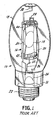
- Fig. 1 is a perspective view of a prior art protected arc discharge lamp;
- Fig. 2 is an elevational view of a protected arc discharge lamp according to an embodiment of the invention; and
- For a better understanding of the present invention, together with other and further objects, advantages and capabilities thereof, reference is made to the following disclosure and appended claims taken in conjunction with the above-described drawings.
- Referring now to the drawings with greater particularity, there is shown in Fig. 1 an exemplary prior art metal halide
arc discharge lamp 10 of the type known as protected lamps. The lamp includes alamp envelope 12 and anarc tube 14 mounted within the envelope by mountingframe 16. The arc tube may be positioned within ashroud 20 which can also be supported by themounting frame 16. Electrical energy is coupled to thearc tube 14 through abase 22, alamp stem 24, andelectrical leads shroud 20 comprises a cylindrical tube of light-transmissive, heat-resistant material such as quartz. - As noted, in this particular instance, the
mounting frame 16 supports both thearc tube 14 and theshroud 20 within thelamp envelope 12. Themounting frame 16 includes ametal support rod 30 attached tolamp stem 24 by astrap 31. The support rod engages aninward projection 32 in the upper end of thelamp envelope 12. Thesupport rod 30 in its central portion is parallel to a central axis of thearc tube 14 andshroud 20. The mounting means 16 further includes anupper clip 40 and alower clip 42, which secure botharc tube 14 andshroud 20 to supportrod 30. Theclips support rod 30, preferably by welding. - Referring now to Fig. 2 there is shown a high
intensity discharge lamp 10a containing anunshrouded arc tube 14a mounted in an outer envelope 1 2a, the outer envelope being surrounded by aprotective device 50. Thedevice 50 comprises atranslucent pocket 52 constructed of a fine mesh having a strength component sufficient to retain any shards from the outer envelope or arc tube in the event of an arc tube burst. - The material from which the mesh is constructed or woven must be capable of sustaining the temperatures involved in an operating lamp, and these temperatures can approach ≈ 250° C for the outer envelope and more than 1000° C for fragments of a burst arc tube.
- A preferred material for the
protective device 50 is a stainless steel screen of 50 mesh/inch, woven of wire having a diameter of 0.0012 inches. Other screen sizes and materials may be appropriate provided they meet the temperature requirements necessitated by the operating lamp. The screen is extremely pliable and easily can be fashioned to accommodate many different lamp shapes. - Inclusion of the
protective device 50 will have some effect on the lumen output of the lamp; however, tests have shown such effects to be minimal. For example, tests were run on a 400 watt lamp with and without theprotective device 50. The results are shown in Table I below.TABLE I Description Lumens % Lumen Change Device vs. No Device Efficacy (LPW) No Device - Try 1 40,160 100.4 Device On 37,560 6.7 93.9 No Device - Try 2 39,630 5.4 99.1 - For the first try, the lamp was aged for one hour without the protective device and then the light output was measured. Then the protective device was placed over the lamp and held in place with a clamp, the lamp was aged for an additional 15 minutes and the light output was measured again, and finally, the protective device was removed, the lamp was again aged for 15 minutes and the light output measured for the third time, with the results shown in the table as Try 2.
- As shown in Table I the protective device lowered the lumen output by only about 6%.
- To determine the efficacy of the protective device it is necessary to cause a burst of the arc tube in an operating lamp. A standard method to test the containment of metal halide lamps is the capacitor discharge method which involves discharging a capacitor bank through the lamp; however, a new testing method was developed.
- The new testing method comprises mounting a lamp with a protective device in position in a transparent enclosure of, for example plastic. A tray was placed underneath the lamp to catch any fragments or shards. The lamp was then operated for 10 minutes. After the warm-up period a laser was focused upon the arc tube and within 20 seconds the arc tube burst violently, exploding into many pieces. An exhaust system removes all potentially hazardous gases from the enclosure. The outer envelope glass was found to have many cracks and holes; however, there was no damage to the protective device and no pieces of the broken arc tube or outer envelope were observed within the plastic enclosure.
- The experiment was conducted with a similar lamp without the protective device and again the arc tube burst and shattered the outer envelope. In the latter test countless pieces of arc tube and outer envelope were found scattered throughout the plastic enclosure.
- The laser used in these test was Nd:YAG laser operating at 532 nm. (The normal operating wavelength of the Nd:YAG laser is 1064 nm. Since the infrared output of the laser is difficult to work with, it was doubled to 532 nm, a visible wavelength, using a standard method.) The pulse width was 3 ns and the linewidth was 250 MHz. The repetition rate was 30 Hz and the laser power was ≈ 100 mJ. The laser beam was focused onto the arc tube using a 500 mm focal length, plano-convex cylindrical lens. The focal plane was therefore line-shaped and oriented vertically along the vertical arc tube wall. The plastic enclosure had a rectangular slot in one of the walls so the laser beam could enter the chamber. When testing the protected lamp it was necessary to provide a slot in the mesh also to allow the laser beam to encounter the arc tube. The slot in the mesh was small (10 x 3 mm).
- This method has an advantage over the capacitive discharge method since the laser allows one to choose where on the arc tube to cause the fracture. Additionally, the capacitive discharge test adds a great amount of energy to the arc tube, thereby increasing the temperature and pressure within the arc tube. This added energy causes a more energetic explosion than observed for actual lamp failures. Since the laser does not add energy to the contents of the arc tube, except in a highly localized area, it offers a more realistic simulation of actual lamp failures. The laser method also offers the possibility of causing small leaks in the arc tube without causing an explosive failure. In this case, a standard plano-convex or biconvex lens (not a cylindrical lens) is used to focus the laser on to the arc tube.
- When tested as above, the arc tube of the unprotected lamp burst in as little as 3 to as long as 20 seconds. In the protected lamp, the arc tube burst in about 20 seconds. The laser parameters may be varied widely within this method. For example, a repetition rate of 90 Hz will burst the arc tube three times faster than at 30 Hz. Laser power may also be adjusted to affect the bursting time. A variety of wavelengths may be utilized provided the wavelength is not significantly absorbed prior to reaching the arc tube, e.g., by the glass outer jacket.
- There is thus provided a lamp that can be adapted to be used in protected lamp environments after its manufacture, at a cost substantially less than a lamp initially manufactured for such use.
- A novel kit is provided allowing an end user to retrofit a lamp for use in situations requiring a protected lamp.
- Also, a new method for testing lamps for burst consequences is provided.
- While there have been shown and described what are present considered to be the preferred embodiments of the invention, it will be apparent to those skilled in the art that various changes and modifications can be made herein without departing from the scope of the invention as defined by the appended claims.
Claims (11)
- A protective device for a high intensity discharge lamp containing an arc tube within an outer envelope comprising:a translucent pocket formed to fit over said outer envelope of said lamp, said translucent pocket being constructed of a fine mesh having a strength sufficient to retain any shards from said lamp in the event of an arc tube burst.
- The protective device of Claim 1 wherein said fine mesh is stainless steel.
- The protective device of Claim 2 wherein said fine mesh is 50 mesh per inch.
- The protective device of Claim 3 wherein said mesh is constructed of wire having a diameter of 0.0012 inches.
- A kit for adding burst protection to a high intensity discharge lamp having an arc tube mounted in an outer envelope, said kit comprising:a translucent pocket formed to fit over said outer envelope of said lamp, said translucent pocket being constructed of a fine mesh having a strength sufficient to retain any shards from said lamp in the event of an arc tube burst; anda clamp for positioning and holding said mesh on said outer envelope.
- A protected high intensity discharge lamp having an arc tube mounted in an outer envelope comprising:a translucent pocket formed to fit over said outer envelope of said lamp, said translucent pocket being constructed of a fine mesh having a strength sufficient to retain any shards from said lamp in the event of an arc tube burst, said translucent pocket being fixed to said lamp outer envelope.
- A method for bursting the arc tube of a high intensity discharge lamp comprising the steps of:operating said lamp for a sufficient time to achieve warm-up conditions;focusing a laser on to said arc tube; andenergizing said laser at a power and for a time sufficient to cause said arc tube to burst.
- The method of Claim 7 wherein said laser is a Nd:YAG laser.
- The method of Claim 8 wherein said laser is operated at 532 nm with a pulse width of laser radiation of 3 ns; a line width of 250MHz; a repetition rate of 30 Hz and a power of about 100 mJ.
- The method of Claim 9 wherein said laser is focused onto said arc tube via a 500 mm focal length, plano-convex lens.
- The method of Claim 7 wherein the lamp is mounted within an enclosure and the laser is focused on to the arc tube through a window in the enclosure.
Applications Claiming Priority (1)
| Application Number | Priority Date | Filing Date | Title |
|---|---|---|---|
| US10/711,264 US20060049733A1 (en) | 2004-09-07 | 2004-09-07 | Protected Metal Halide Lamp |
Publications (2)
| Publication Number | Publication Date |
|---|---|
| EP1632984A2 true EP1632984A2 (en) | 2006-03-08 |
| EP1632984A3 EP1632984A3 (en) | 2007-09-05 |
Family
ID=35519639
Family Applications (1)
| Application Number | Title | Priority Date | Filing Date |
|---|---|---|---|
| EP05018822A Withdrawn EP1632984A3 (en) | 2004-09-07 | 2005-08-30 | Protected metal halide lamp |
Country Status (4)
| Country | Link |
|---|---|
| US (1) | US20060049733A1 (en) |
| EP (1) | EP1632984A3 (en) |
| JP (1) | JP2006080080A (en) |
| CA (1) | CA2510527A1 (en) |
Cited By (2)
| Publication number | Priority date | Publication date | Assignee | Title |
|---|---|---|---|---|
| DE102006030275A1 (en) * | 2006-06-30 | 2008-01-03 | Patent-Treuhand-Gesellschaft für elektrische Glühlampen mbH | Protective cover for lamps and associated structural unit |
| DE102010031512A1 (en) | 2010-07-19 | 2012-01-19 | Osram Gesellschaft mit beschränkter Haftung | Ballast e.g. electronic ballast, and lamp e.g. blow-out protected high pressure discharge lamp, combined system, has lamp designed such that no burner components leave lamp with power multiplied with safety factor during placement of burner |
Families Citing this family (6)
| Publication number | Priority date | Publication date | Assignee | Title |
|---|---|---|---|---|
| US20080030138A1 (en) * | 2006-08-02 | 2008-02-07 | Turner Allen P | Lamp Cover |
| KR101271341B1 (en) | 2007-10-22 | 2013-06-04 | 우시오덴키 가부시키가이샤 | Long-arc type discharge lamp and ultraviolet irradiation apparatus comprising long-arc type discharge lamp |
| CN101644423B (en) * | 2008-08-08 | 2011-03-30 | 鸿富锦精密工业(深圳)有限公司 | Light source protection device |
| USD866128S1 (en) | 2017-09-25 | 2019-11-12 | Jonathan McCann | Shade for a headlamp |
| USD890477S1 (en) | 2017-09-25 | 2020-07-21 | Jonathan McCann | Shade for a headlamp |
| US10203099B1 (en) | 2017-09-25 | 2019-02-12 | Jonathan McCann | Shade for a headlamp |
Citations (11)
| Publication number | Priority date | Publication date | Assignee | Title |
|---|---|---|---|---|
| GB471900A (en) * | 1935-08-13 | 1937-09-13 | Jean Baptiste Joseph Marcel Ab | Electric metallic-vapour arc discharge lamps |
| FR852426A (en) * | 1938-04-02 | 1940-02-01 | Philips Nv | Further development of incandescent electric lamps |
| US3223273A (en) * | 1962-09-07 | 1965-12-14 | Duro Test Corp | Reinforced envelope for light source and method of making |
| US4721876A (en) * | 1982-09-23 | 1988-01-26 | Gte Products Corporation | Light-source capsule containment device and lamp employing such device |
| EP0104595B1 (en) * | 1982-09-23 | 1990-07-04 | GTE Products Corporation | Double-enveloped incandescent lamp |
| EP0645800A1 (en) * | 1993-09-24 | 1995-03-29 | Koninklijke Philips Electronics N.V. | High pressure discharge lamp |
| EP0720209A2 (en) * | 1994-12-06 | 1996-07-03 | Flowil International Lighting (Holding) B.V. | Discharge lamps |
| US5576591A (en) * | 1993-05-24 | 1996-11-19 | Blv Licht-Und Vakuumtechnik Gmbh | Gas discharge lamp having a transparent envelope bulk and a bursting guard |
| EP1024515A1 (en) * | 1999-01-27 | 2000-08-02 | Matsushita Electronics Corporation | Method for manufacturing a discharge tube |
| EP1160821A2 (en) * | 2000-05-30 | 2001-12-05 | Patent-Treuhand-Gesellschaft für elektrische Glühlampen mbH | Method of inscribing quartz glass lamps and quartz glass lamps made thereby |
| DE10133073C1 (en) * | 2001-05-16 | 2002-07-25 | Paul P Frankenbach | Contactless discharge lamp socket removal device uses infrared laser beam directed onto outside of lamp tube during its rotation about its longitudinal axis |
Family Cites Families (6)
| Publication number | Priority date | Publication date | Assignee | Title |
|---|---|---|---|---|
| US4281274A (en) * | 1979-08-01 | 1981-07-28 | General Electric Co. | Discharge lamp having vitreous shield |
| US4580989A (en) * | 1982-08-18 | 1986-04-08 | Gte Products Corporation | Metal halide arc discharge lamp with means for suppressing convection currents within the outer envelope and methods of operating and constructing same |
| US4499396A (en) * | 1982-08-18 | 1985-02-12 | Gte Products Corporation | Metal halide arc discharge lamp with means for suppressing convection currents within the outer envelope and methods of operating same |
| US5039912A (en) * | 1989-09-08 | 1991-08-13 | U.S. Philips Corporation | High-pressure discharge lamp |
| US5023506A (en) * | 1989-12-28 | 1991-06-11 | North American Philips Corporation | Explosion proof high pressure discharge lamp |
| DE4230814A1 (en) * | 1992-09-15 | 1994-03-17 | Patent Treuhand Ges Fuer Elektrische Gluehlampen Mbh | High pressure discharge lamp |
-
2004
- 2004-09-07 US US10/711,264 patent/US20060049733A1/en not_active Abandoned
-
2005
- 2005-06-22 CA CA002510527A patent/CA2510527A1/en not_active Abandoned
- 2005-08-30 EP EP05018822A patent/EP1632984A3/en not_active Withdrawn
- 2005-09-07 JP JP2005259440A patent/JP2006080080A/en active Pending
Patent Citations (11)
| Publication number | Priority date | Publication date | Assignee | Title |
|---|---|---|---|---|
| GB471900A (en) * | 1935-08-13 | 1937-09-13 | Jean Baptiste Joseph Marcel Ab | Electric metallic-vapour arc discharge lamps |
| FR852426A (en) * | 1938-04-02 | 1940-02-01 | Philips Nv | Further development of incandescent electric lamps |
| US3223273A (en) * | 1962-09-07 | 1965-12-14 | Duro Test Corp | Reinforced envelope for light source and method of making |
| US4721876A (en) * | 1982-09-23 | 1988-01-26 | Gte Products Corporation | Light-source capsule containment device and lamp employing such device |
| EP0104595B1 (en) * | 1982-09-23 | 1990-07-04 | GTE Products Corporation | Double-enveloped incandescent lamp |
| US5576591A (en) * | 1993-05-24 | 1996-11-19 | Blv Licht-Und Vakuumtechnik Gmbh | Gas discharge lamp having a transparent envelope bulk and a bursting guard |
| EP0645800A1 (en) * | 1993-09-24 | 1995-03-29 | Koninklijke Philips Electronics N.V. | High pressure discharge lamp |
| EP0720209A2 (en) * | 1994-12-06 | 1996-07-03 | Flowil International Lighting (Holding) B.V. | Discharge lamps |
| EP1024515A1 (en) * | 1999-01-27 | 2000-08-02 | Matsushita Electronics Corporation | Method for manufacturing a discharge tube |
| EP1160821A2 (en) * | 2000-05-30 | 2001-12-05 | Patent-Treuhand-Gesellschaft für elektrische Glühlampen mbH | Method of inscribing quartz glass lamps and quartz glass lamps made thereby |
| DE10133073C1 (en) * | 2001-05-16 | 2002-07-25 | Paul P Frankenbach | Contactless discharge lamp socket removal device uses infrared laser beam directed onto outside of lamp tube during its rotation about its longitudinal axis |
Cited By (2)
| Publication number | Priority date | Publication date | Assignee | Title |
|---|---|---|---|---|
| DE102006030275A1 (en) * | 2006-06-30 | 2008-01-03 | Patent-Treuhand-Gesellschaft für elektrische Glühlampen mbH | Protective cover for lamps and associated structural unit |
| DE102010031512A1 (en) | 2010-07-19 | 2012-01-19 | Osram Gesellschaft mit beschränkter Haftung | Ballast e.g. electronic ballast, and lamp e.g. blow-out protected high pressure discharge lamp, combined system, has lamp designed such that no burner components leave lamp with power multiplied with safety factor during placement of burner |
Also Published As
| Publication number | Publication date |
|---|---|
| EP1632984A3 (en) | 2007-09-05 |
| JP2006080080A (en) | 2006-03-23 |
| US20060049733A1 (en) | 2006-03-09 |
| CA2510527A1 (en) | 2006-03-07 |
Similar Documents
| Publication | Publication Date | Title |
|---|---|---|
| EP1632984A2 (en) | Protected metal halide lamp | |
| EP3143638B1 (en) | Laser driven sealed beam lamp | |
| JP7361748B2 (en) | Laser-driven sealed beam lamp with improved stability | |
| JPH1051081A (en) | Excimer radiator, its manufacture, its life-time prolongation method and apparatus for performing the method | |
| JP2000048772A (en) | Dielectric barrier discharge lamp and irradiation device | |
| EP1056119B1 (en) | Cold-end device of a low-pressure mercury vapour discharge lamp | |
| JP2006236919A (en) | High pressure metallic vapor discharge lamp and luminaire | |
| US7417363B2 (en) | Containment vessel for light source capsules operating at other than the pressure of a surrounding gas | |
| US7511406B2 (en) | Metal halide arc discharge lamp | |
| EP1704576B1 (en) | Method of manufacturing a compact high-pressure discharge lamp | |
| CN101436515B (en) | Metal halide lamp and UV bubble structure thereof | |
| JPH06295708A (en) | Metal halide arc lamp with shroud for containment made of glass | |
| US7701140B2 (en) | High-pressure discharge lamp | |
| SU1571697A1 (en) | Gas-discharge electrodeless high-frequency lamp and method of manufacturing same | |
| JP2006236985A (en) | High pressure metallic vapor discharge lamp and lighting apparatus | |
| JPH09283081A (en) | Cold cathode low pressure mercury vapor discharge lamp, display device and lighting system | |
| EP3533079A1 (en) | Apparatus and a method for operating a variable pressure sealed beam lamp | |
| JP2003282020A (en) | Discharge lamp | |
| JPH05334962A (en) | Manufacture of metal vapor discharge lamp | |
| JP2009129910A (en) | Ceramic high luminance discharge arc tube assembly | |
| JP2011065942A (en) | High-pressure metal vapor discharge lamp and illumination device |
Legal Events
| Date | Code | Title | Description |
|---|---|---|---|
| PUAI | Public reference made under article 153(3) epc to a published international application that has entered the european phase |
Free format text: ORIGINAL CODE: 0009012 |
|
| AK | Designated contracting states |
Kind code of ref document: A2 Designated state(s): AT BE BG CH CY CZ DE DK EE ES FI FR GB GR HU IE IS IT LI LT LU LV MC NL PL PT RO SE SI SK TR |
|
| AX | Request for extension of the european patent |
Extension state: AL BA HR MK YU |
|
| RIC1 | Information provided on ipc code assigned before grant |
Ipc: H01J 9/42 20060101ALN20070502BHEP Ipc: H01J 61/34 20060101ALI20070502BHEP Ipc: H01J 61/50 20060101AFI20070502BHEP |
|
| PUAL | Search report despatched |
Free format text: ORIGINAL CODE: 0009013 |
|
| AK | Designated contracting states |
Kind code of ref document: A3 Designated state(s): AT BE BG CH CY CZ DE DK EE ES FI FR GB GR HU IE IS IT LI LT LU LV MC NL PL PT RO SE SI SK TR |
|
| AX | Request for extension of the european patent |
Extension state: AL BA HR MK YU |
|
| AKX | Designation fees paid | ||
| STAA | Information on the status of an ep patent application or granted ep patent |
Free format text: STATUS: THE APPLICATION IS DEEMED TO BE WITHDRAWN |
|
| 18D | Application deemed to be withdrawn |
Effective date: 20080303 |
|
| REG | Reference to a national code |
Ref country code: DE Ref legal event code: 8566 |