EP1633266B1 - Apparatus for treating atrial fibrillation using high intensity focused ultrasound - Google Patents
Apparatus for treating atrial fibrillation using high intensity focused ultrasound Download PDFInfo
- Publication number
- EP1633266B1 EP1633266B1 EP04754905.0A EP04754905A EP1633266B1 EP 1633266 B1 EP1633266 B1 EP 1633266B1 EP 04754905 A EP04754905 A EP 04754905A EP 1633266 B1 EP1633266 B1 EP 1633266B1
- Authority
- EP
- European Patent Office
- Prior art keywords
- hifu
- high intensity
- intensity focused
- focused ultrasound
- ultrasound
- Prior art date
- Legal status (The legal status is an assumption and is not a legal conclusion. Google has not performed a legal analysis and makes no representation as to the accuracy of the status listed.)
- Not-in-force
Links
Images


Classifications
-
- A—HUMAN NECESSITIES
- A61—MEDICAL OR VETERINARY SCIENCE; HYGIENE
- A61N—ELECTROTHERAPY; MAGNETOTHERAPY; RADIATION THERAPY; ULTRASOUND THERAPY
- A61N7/00—Ultrasound therapy
- A61N7/02—Localised ultrasound hyperthermia
-
- A—HUMAN NECESSITIES
- A61—MEDICAL OR VETERINARY SCIENCE; HYGIENE
- A61B—DIAGNOSIS; SURGERY; IDENTIFICATION
- A61B8/00—Diagnosis using ultrasonic, sonic or infrasonic waves
- A61B8/12—Diagnosis using ultrasonic, sonic or infrasonic waves in body cavities or body tracts, e.g. by using catheters
-
- A—HUMAN NECESSITIES
- A61—MEDICAL OR VETERINARY SCIENCE; HYGIENE
- A61B—DIAGNOSIS; SURGERY; IDENTIFICATION
- A61B8/00—Diagnosis using ultrasonic, sonic or infrasonic waves
- A61B8/44—Constructional features of the ultrasonic, sonic or infrasonic diagnostic device
- A61B8/4483—Constructional features of the ultrasonic, sonic or infrasonic diagnostic device characterised by features of the ultrasound transducer
- A61B8/4488—Constructional features of the ultrasonic, sonic or infrasonic diagnostic device characterised by features of the ultrasound transducer the transducer being a phased array
-
- A—HUMAN NECESSITIES
- A61—MEDICAL OR VETERINARY SCIENCE; HYGIENE
- A61B—DIAGNOSIS; SURGERY; IDENTIFICATION
- A61B17/00—Surgical instruments, devices or methods, e.g. tourniquets
- A61B17/00234—Surgical instruments, devices or methods, e.g. tourniquets for minimally invasive surgery
- A61B2017/00238—Type of minimally invasive operation
- A61B2017/00243—Type of minimally invasive operation cardiac
-
- A—HUMAN NECESSITIES
- A61—MEDICAL OR VETERINARY SCIENCE; HYGIENE
- A61B—DIAGNOSIS; SURGERY; IDENTIFICATION
- A61B18/00—Surgical instruments, devices or methods for transferring non-mechanical forms of energy to or from the body
- A61B2018/00315—Surgical instruments, devices or methods for transferring non-mechanical forms of energy to or from the body for treatment of particular body parts
- A61B2018/00345—Vascular system
- A61B2018/00351—Heart
-
- A—HUMAN NECESSITIES
- A61—MEDICAL OR VETERINARY SCIENCE; HYGIENE
- A61B—DIAGNOSIS; SURGERY; IDENTIFICATION
- A61B90/00—Instruments, implements or accessories specially adapted for surgery or diagnosis and not covered by any of the groups A61B1/00 - A61B50/00, e.g. for luxation treatment or for protecting wound edges
- A61B90/36—Image-producing devices or illumination devices not otherwise provided for
- A61B90/37—Surgical systems with images on a monitor during operation
- A61B2090/378—Surgical systems with images on a monitor during operation using ultrasound
- A61B2090/3782—Surgical systems with images on a monitor during operation using ultrasound transmitter or receiver in catheter or minimal invasive instrument
-
- A—HUMAN NECESSITIES
- A61—MEDICAL OR VETERINARY SCIENCE; HYGIENE
- A61B—DIAGNOSIS; SURGERY; IDENTIFICATION
- A61B8/00—Diagnosis using ultrasonic, sonic or infrasonic waves
- A61B8/08—Detecting organic movements or changes, e.g. tumours, cysts, swellings
- A61B8/0883—Detecting organic movements or changes, e.g. tumours, cysts, swellings for diagnosis of the heart
-
- A—HUMAN NECESSITIES
- A61—MEDICAL OR VETERINARY SCIENCE; HYGIENE
- A61N—ELECTROTHERAPY; MAGNETOTHERAPY; RADIATION THERAPY; ULTRASOUND THERAPY
- A61N7/00—Ultrasound therapy
- A61N2007/0078—Ultrasound therapy with multiple treatment transducers
Definitions
- the present invention relates to an apparatus for treatment of atrial fibrillation, and more particularly, to an apparatus using high intensity focused ultrasound non-invasively to disrupt abnormal cardiac electrical pathways contributing to atrial fibrillation.
- US 5 391 140 relates to therapy apparatus configured for rectal insertion for prostate treatment.
- the apparatus has focused, therapeutic ultrasound waves having a first frequency, which includes an ultrasound locating system that emits diagnostic ultrasound that has a second frequency.
- the ultrasound locating system also receives parts of the diagnostic ultrasound reflected in the body of the subject and converts them into electrical signals which are used to form an image of the zone to be treated.
- FR 2 827 149 relates to a treatment probe for focussed ultrasound comprising: a probe body which is mounted in rotation around an axis; an elongated treatment transducer with a focussed ultrasound emission acoustic axis which is more or less the same as the rotation axis of the probe body; and an imaging transducer, the imaging plane of which contains the acoustic axis of the treatment transducer.
- the inventive probe can be used to provide a simple treatment.
- the probe body can be rotated around the axis in order to vary the direction of the imaging plane without moving the focus which always remains in the imaging plane.
- the treatment transducer can be extended in order to provide safer treatment in relation to the organs to be treated and without risk of damaging the fragile surrounding organs.
- the focused ultrasound probe has a casing which rotates around an axis.
- the image transducer has a bar shape giving a linear sweep, its axis is parallel to the longitudinal direction of the treatment transducer.
- US 5 817 021 relates to a therapy apparatus and method for treating conditions of the heart and, particularly, of heart-proximate vessels with therapeutic ultrasound waves having a therapeutically effective region.
- the therapy apparatus generates therapeutic ultrasound waves with such intensity that tissue modifications, particularly necrotization, are produced in the tissue located in the region of influence.
- the therapy apparatus preferably contains an ultrasound source that can be transesophageally applied.
- WO 01/82778 relates to a method of treating tissue that includes providing orienting the transducers adjacent the treatment region, exciting the transducers to treat the tissue, and flushing fluid over the transducers.
- the apparatus for treating tissue includes a catheter, a device for monitoring the temperature adjacent the transducers, at least one transducer driver for exciting the transducers to treat the tissue, and a source providing a flow of fluid through the lumen and over the transducers.
- GB 2 267 035 relates to a catheter comprising an ultrasonic transducer at its distal end and an electrode mounted in proximity thereto for receiving electrical cardiac signals to enable positioning of the transducer. Wires traverse the length of the catheter to connect the electrode with external monitoring equipment such as an electrocardiograph.
- the transducer which may be of single crystal or phased array crystal type, delivers ultrasonic energy to myocardial tissue at frequencies sufficient to destroy tissue implicated in arrhythmia.
- WO 89/07909 relates to a transducer assembly for visualization and treatment of transcutaneous and intraoperative sites.
- the assembly includes a visualization transducer and a treatment transducer, each of which are movable with both linear and rotary degrees of freedom. Movement of each transducer is by various motor and geared drive arrangements wherein certain degrees of freedom for one transducer are separate and independent from the degrees of freedom for the other transducer. At least one degree of freedom for each transducer is common and the transducers are moved concurrently.
- One arrangement of the transducer combination is for prostate treatment and includes a specific shape and configuration for anatomical considerations and a control unit which is operable external to the patient to control both transducers and a reflective scanner which are inserted into the patient as part of the ultrasound probe.
- Dr. James Cox invented a new open-heart surgical procedure that interrupted depolarization waves using surgical incisions in the walls of the atrium. More recently, a number of devices have been developed to allow surgeons to make such lesions during surgery on the beating heart, and without making incisions in the walls of the atrium. More recently, interventional electrophysiologists have worked with companies to develop catheter-based systems to create similar lesions. Although only partial success has been achieved to date, there is optimism for further progress within the next few years.
- Radio-frequency electrical energy, microwaves, cryothermia probes, alcohol injection, laser light, and ultrasound energy are just a few of the technologies that have been pursued.
- Therus Corp of Seattle has developed a system to seal blood vessels after the vessels have been punctured to insert sheaths and catheters.
- the Therus system shrinks and seals femoral artery punctures at a depth of approximately 5 cm.
- Timi-3 Systems, Inc. has developed and is testing a trans-thoracic ultrasound energy delivery system to accelerate the thrombolysis process for patients suffering an acute myocardial infarction. This system delivers energy at a frequency intended to accelerate thrombolysis without damaging the myocardium or vasculature of the heart.
- the Epicor Medical, Inc. of Sunnyvale, CA has developed a localized high intensity focused ultrasound ("HIFU") device to create lesions in the atrial walls.
- the Epicor device is a hand-held intraoperative surgical device, and is configured to be held directly against the epicardium or outside wall of the heart. When energized, the device creates full-thickness lesions through the atrial wall of the heart, and has demonstrated that ultrasound energy may be safely and effectively used to create atrial lesions, despite presence of blood flow past the interior wall of the atrium.
- Transurgical, Inc., Setauket, NY has been actively developing HIFU devices.
- Epicor Medical devices are placed in close approximation against the outside of the heart, the Transurgical devices are directed to intravascular catheters for ablating tissue in the heart by bringing the catheter into close approximation with the targeted tissue.
- an apparatus for intraluminally treating atrial fibrillation according to the appended claims.
- the apparatus of the present invention is expected to be cost-effective and to perform time efficient compared to the previously-known surgical and interventional procedures.
- the present disclosure is directed to methods and apparatus for creating lesions in the walls of the heart in a completely non-invasive manner using high intensity focused ultrasound (HIFU).
- HIFU high intensity focused ultrasound
- Previously-known HIFU systems such as those being developed by Epicor Medical or Transurgical, require close approximation of the HIFU device to the target tissue.
- the methods and apparatus of the present disclosure overcome this drawback by providing a system that enables the creation of lesions in the heart wall from a greater distance.
- System 10 comprises head 11 housing ultrasound imaging system 12 and high intensity focused ultrasound energy ("HIFU") system 14.
- Ultrasound imaging system 12 and HIFU system 14 may have in common all or just a subset of the transducers and related components, operating in different modes to image or ablate.
- Head 11 is mounted on arm 13 that permits the head to be positioned in contact with a patient (not shown) lying on table 15. Head 11 may also be a handheld unit, not needing an arm 13 to support or position it.
- System 10 includes controller 16 that controls operation of imaging system 12 and HIFU system 14.
- Monitor 18 displays images output by imaging system 12 that allows the clinician to identify the desired locations on the walls of the heart to be treated.
- Controller 16 and monitor 18 also are programmed to indicate the focus of the HIFU energy relative to the image of the tissue cross-section.
- FIG. 2 is illustrative screen display 19 of monitor 18 showing the outline T of the tissue, as imaged by imaging system 12, and a marker corresponding to the location of focal point F of HIFU system 14.
- the HIFU system When activated, the HIFU system delivers ablative energy to the specific location shown on monitor 18 (focal point F in FIG. 2 ), thus enabling safe creation of transmural lesions. Because the HIFU system is configured to deliver energy from a number of sources focused towards the target tissue area, intervening tissue is subjected to only a fraction of the energy deposited in the target tissue receives, and thus the intervening tissue is not significantly heated or ablated.
- ultrasound imaging system 12 may be similar in design to previously-known trans-thoracic ultrasound imaging systems, and are per se known.
- High intensity focused ultrasound system 14 may comprise one or more HIFU generators 20 constructed as described in U. S. Patent Application No. US20010031922A1 .
- imaging system 12 and HIFU system 14 may also use the same elements.
- each HIFU generator 20 is the same as or is disposed approximately in the same plane as the imaging elements of ultrasound imaging system 12, so that the focus of HIFU system 14 occurs in the plane of the target tissue imaged by ultrasound imaging system 12.
- this arrangement advantageously ensures that the HIFU energy will reach the target.
- HIFU generators 20 deliver energy at a frequency optimized for creating lesions in myocardium, to thereby interrupt conduction pathways through the tissue without reducing the strength of the tissue. Once the lesions are created, a gradual healing process is begun in which the lesions fibrose, but do not fall apart or regain the ability to conduct electrical impulses.
- controller 16 may be programmed to time-gate operation of imaging system 12 and HIFU system 14, so that the tissue is alternately imaged and ablated at a frequency of several times per second.
- Controller 16 may include suitable programming and joystick 22, or other input device, for refocusing the focal point of HIFU system 14 along a desired trajectory.
- FIG. 3 a further alternative for using HIFU system to create linear lesions is described.
- the focus of the HIFU system is fixed at a certain point within the field of the ultrasound image.
- the ultrasound image might show a picture of rectangular planar cross-section of tissue approximately 80 mm wide and 160 mm deep, with a fixed focus of the HIFU energy at a depth of 130 mm in the center of the field.
- the clinician manually moves the probe until the desired tissue is in the target area, and then fires the HIFU system to ablate the tissue.
- the depth of maximal ablation is 130 mm below the skin.
- the HIFU system includes fluid-filled balloon 24 that covers the face of the probe.
- Balloon 24 preferably is filled with water and enables the clinician to reposition the probe at a variable distance from the skin. Balloon 24 also permits the clinician to position the probe at any desired angle to target tissue not aligned directly under the focal point of HIFU system 14.
- the patient could sit in a tub of water, so the patient's chest and the probe were both underwater, again ensuring a continuous fluid path.
- controller 16 may be programmed so that the depth of the focal point of the HIFU system is depth-adjustable relative to the imaged tissue.
- the depth of the targeted tissue could then be adjusted relative to the imaged field, so a smaller fluid-filled balloon, or no balloon, is used to maintain fluid contact while adjusting the angle of the imaged section or make minor changes in the depth of the targeted tissue.
- WIPO Patent Publication No. WO/0145550A2 to Therus describes several ways to adjust the depth of the focused energy by changing the radius of curvature of one or more of the ultrasound generators. Alternatively, the direction of several focused energy generators of relatively fixed focal length could be shifted relative to one another to move the focal point.
- focused energy is applied from outside the patient's body. Because ultrasound energy does not travel coherently through non-fluid filled tissue, such as the lungs, positioning of the ultrasound imaging system and HIFU system at certain angles may be more advantageous for treatment of specific areas of the heart. For example, the posterior wall of the left atrium is a particularly important treatment area for treating atrial fibrillation; it is also a peculiarly difficult area to image with trans-thoracic ultrasound.
- the imaging system and HIFU system may be desirable to locate the imaging system and HIFU system on a movable arm or to position it by hand so as to permit other external approaches, such as from below the diaphragm on the left anterior side of the body, so the ultrasound has a coherent path through the diaphragm and apex and ventricles of the heart to the atria.
- Application of the probe to a patient's back also may provide a coherent path to the posterior wall of the patient's left atrium.
- the system and methods of the disclosed example also may be useful for treating a number of cardiac dysfunctions.
- the methods and apparatus also may be used to treat other electrophysiologic defects of the heart, or to create lesions for other purposes.
- TMR transmyocardial revascularization
- PFO patent foramen ovale
- the HIFU system described hereinabove also may be used to repair diseased heart valves, by shrinking tissue in certain areas. For example, specific areas of elongated chordae of a mitral valve leaflet may be shortened by heating using the external HIFU.
- Intraluminal probe 30 is configured to deliver HIFU energy to the heart from the esophagus, from the aorta, or from the great veins of the heart such as the inferior vena cava, superior vena cava, or the right atrium itself.
- previously-known devices are capable of making only a single lesion from a given position, rather than forming a number of lesions at a distance from a device from a single location.
- Making multiple lesions from a single catheter position advantageously may save time and reduce the cost of the procedure.
- approximating a surgical maze procedure using previously-known intracardiac catheters typically takes from four to eight hours, and subject both the patient and physician to high levels of radiation from the fluoroscope.
- a device constructed in accordance with the principles of the present invention, under ultrasound imaging guidance could create multiple lesions while disposed at a single position in the esophagus, aorta, or great veins or right atrium.
- intraluminal catheter 30 is designed to image and deliver HIFU energy from body lumens such as the esophagus, aorta, and great veins.
- Catheter 30 preferably has a diameter in a range of 5 to 10 mm for vascular devices, and a diameter in a range of 5 to 20 mm for an esophageal device.
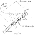
- Imaging elements 32 and HIFU elements 34 are arranged linearly along the longitudinal axis of the catheter.
- the linear nature of the imaging element and HIFU element array may impose limitations on the ability to reposition the device. While translation and rotation of the catheter may be relatively easy, it is contemplated that it may be difficult to move the device very far to one side or another within a relatively small-diameter body lumen.
- intraluminal catheter 30 preferably is configured to adjust the focal point of the HIFU system with respect to both longitudinal position and depth. This may be accomplished by programming the controller used with intraluminal catheter 30 to adjust the focal point of the HIFU system, as described above. Alternatively, refocusing of the array of HIFU elements may be achieved by locating individual HIFU elements on independently steerable actuators 36. Actuators 36 are controlled by the system controller and permit the clinician to move the focal point of the HIFU array to any desired point in the field of view of the imaging system.
- the esophagus is separated from the center of the posterior left atrial wall only by the oblique pericardial sinus, so a linear vertical lesion may be easily made in the center of the posterior left atrial wall using a probe capable of delivering energy at a distance of approximately 5-10 mm.
- Such methods are believed to offer substantial advantages with respect to ease of use, and may be effective in treating a high percentage of atrial fibrillation patients. These methods also may obviate the need to contract significant areas of the posterior wall of the left atrium, as typically happens when broad encircling lesions are made around the pulmonary veins.
- one or more vertical ablation lines are formed in the posterior wall of the left atrium using intraluminal catheter 30 disposed within the esophagus. It is expected that formation of straight ablation lines vertically in the posterior wall of the atrium, under ultrasound imaging guidance from the esophagus, may also be easier than making encircling ablation lines around the pulmonary veins.
- the maze concept relies on the creation of numerous dead-end pathways in the atria, so the depolarization wave reaches all of the atrial walls, but cannot recirculate.
- a series of vertical ablation lines in the posterior wall of the left atrium, extending from the atrioventricular groove up to above the superior pulmonary veins would accomplish exactly this goal.
- the ablation lines extend all the way down to the atrioventricular groove. This allows the depolarization wave to reach that tissue from the dome of the left atrium (the more cranial and anterior surface) but not to progress back to the rest of the atrial wall along the atrioventricular groove.
- intraluminal catheter 30 preferably is configured, either mechanically or by suitable software algorithms, to move its focal point longitudinally to enable a continuous linear ablation without moving the device.
- the HIFU array of the catheter may be configured to create a linear ablation, or have a fixed-focus so that a linear ablation may be created by translating the HIFU array within the esophagus.
- lesions may be made closer to the left and right pulmonary veins. More preferably, lesions could be made on the opposite sides of the left and right pulmonary veins, i.e., to the left of the left pulmonary veins and to the right of the right pulmonary veins. Alternatively, and depending on the geometry of the HIFU probe, it may be more desirable to make encircling lesions in the left and right pulmonary veins using the same vertical motion.
- Intraluminal catheter 30 may therefore include a water jacket that circulates fluid around the HIFU array to prevent any heat generated by the array or ultrasound energy absorbed by the esophagus from causing any tissue damage.
- the methods and apparatus also may be beneficially applied to other applications besides cardiac dysfunction.
- the apparatus of the present invention may be used, disposed in small body lumens, nearly anywhere a radiofrequency ablation probe is currently being used to ablate or shrink tissue.
- Such treatments include treating the prostate from the urethra, tightening up the bladder neck from inside the vagina, ablating fibroid masses from inside the uterus, tightening up the tissue in the area of the gastroesophageal junction, and so on.
- the external device described with respect to FIG. 1 may be beneficially used to ablate tumors almost anywhere in the body that is accessible to focused ultrasound.
Description
- The present invention relates to an apparatus for treatment of atrial fibrillation, and more particularly, to an apparatus using high intensity focused ultrasound non-invasively to disrupt abnormal cardiac electrical pathways contributing to atrial fibrillation.
-
US 5 391 140 relates to therapy apparatus configured for rectal insertion for prostate treatment. The apparatus has focused, therapeutic ultrasound waves having a first frequency, which includes an ultrasound locating system that emits diagnostic ultrasound that has a second frequency. The ultrasound locating system also receives parts of the diagnostic ultrasound reflected in the body of the subject and converts them into electrical signals which are used to form an image of the zone to be treated. -
FR 2 827 149 -
US 5 817 021 relates to a therapy apparatus and method for treating conditions of the heart and, particularly, of heart-proximate vessels with therapeutic ultrasound waves having a therapeutically effective region. The therapy apparatus generates therapeutic ultrasound waves with such intensity that tissue modifications, particularly necrotization, are produced in the tissue located in the region of influence. The therapy apparatus preferably contains an ultrasound source that can be transesophageally applied. -
WO 01/82778 -
GB 2 267 035 -
WO 89/07909 - Up until the 1980s, there was dramatic growth in the creation of new surgical methods for treating a wide variety of previously untreated conditions. Over the past twenty years there has been a clear trend towards the invention of devices and methods that enable less-invasive treatment of such diseases, moving from invasive surgery, and then to less-invasive surgery, and to interventional techniques. Ultimately, it is desirable to move to totally non-invasive therapies.
- The history of treatment of atrial fibrillation has followed this progression. First, Dr. James Cox invented a new open-heart surgical procedure that interrupted depolarization waves using surgical incisions in the walls of the atrium. More recently, a number of devices have been developed to allow surgeons to make such lesions during surgery on the beating heart, and without making incisions in the walls of the atrium. More recently, interventional electrophysiologists have worked with companies to develop catheter-based systems to create similar lesions. Although only partial success has been achieved to date, there is optimism for further progress within the next few years.
- It would be still more desirable to develop methods of treating atrial fibrillation which were still less invasive, eliminating even the need for catheters.
- A wide variety of energy modes have been used to create lesions using epicardial or intracardiac probes. Radio-frequency electrical energy, microwaves, cryothermia probes, alcohol injection, laser light, and ultrasound energy are just a few of the technologies that have been pursued.
- Separately, several groups have developed focused ultrasound devices with both imaging and therapeutic capabilities. These efforts began perhaps with lithotripsy, in which a high power focused ultrasound system developed by Dornier Medizintechnik, Germany, is used to break up kidney stones in the body. The kidney stones are located within the body at a significant depth from the skin. One ultrasound imaging system is used to aim the system at the kidney stones, and then a second, high energy ultrasound system delivers energy that breaks up the stones so they can be passed.
- More recently, Therus Corp of Seattle has developed a system to seal blood vessels after the vessels have been punctured to insert sheaths and catheters. The Therus system shrinks and seals femoral artery punctures at a depth of approximately 5 cm.
- In addition, Timi-3 Systems, Inc. has developed and is testing a trans-thoracic ultrasound energy delivery system to accelerate the thrombolysis process for patients suffering an acute myocardial infarction. This system delivers energy at a frequency intended to accelerate thrombolysis without damaging the myocardium or vasculature of the heart.
- Epicor Medical, Inc. of Sunnyvale, CA, has developed a localized high intensity focused ultrasound ("HIFU") device to create lesions in the atrial walls. The Epicor device is a hand-held intraoperative surgical device, and is configured to be held directly against the epicardium or outside wall of the heart. When energized, the device creates full-thickness lesions through the atrial wall of the heart, and has demonstrated that ultrasound energy may be safely and effectively used to create atrial lesions, despite presence of blood flow past the interior wall of the atrium.
- In addition, Transurgical, Inc., Setauket, NY has been actively developing HIFU devices. However, while the Epicor Medical devices are placed in close approximation against the outside of the heart, the Transurgical devices are directed to intravascular catheters for ablating tissue in the heart by bringing the catheter into close approximation with the targeted tissue.
- In view of the aforementioned limitations, it would be desirable to provide methods and apparatus for treating atrial fibrillation and other conduction defects by ablating tissue at a distance from that tissue, so that the procedure may be performed non-invasively.
- It also would be desirable to provide methods and apparatus for treating atrial fibrillation by applying energy from outside the body or from organs, such as the esophagus, that are easily accessible via natural body openings.
- In view of the foregoing, it is an object of a disclosed example to provide methods and apparatus for treating atrial fibrillation and other conduction defects by ablating tissue at a distance from that tissue, so that the procedure may be performed noninvasively.
- It is another object of a disclosed example to provide methods and apparatus for treating cardiac dysfunction by applying energy from outside the body or from neighboring organs, such as the esophagus, that are easily accessible.
- These and other objects of the disclosed example(s) are accomplished by providing methods and apparatus that enable a physician to image tissue within the body that is to be ablated, and then to ablate that tissue using a completely or relatively non-invasive procedure, and with little or no anesthesia.
- According to an aspect of the present invention there is provided an apparatus for intraluminally treating atrial fibrillation according to the appended claims.
- Advantageously, the apparatus of the present invention is expected to be cost-effective and to perform time efficient compared to the previously-known surgical and interventional procedures.
- The above and other objects and advantages of the present invention will be apparent upon consideration of the following detailed description, taken in conjunction with the accompanying drawings, in which like reference characters refer to like parts throughout, and in which:
-
FIG. 1 is a schematic view of an illustrative imaging and treatment ultrasound sound system according to a disclosed example; -
FIG. 2 is a schematic view of an illustrative display of the imaging and treatment ultrasound sound system; -
FIG. 3 is a schematic view showing the imaging and treatment ultrasound sound system ofFIG. 1 disposed adjacent to a cross-section of a patient's thorax ; and -
FIG. 4 is a schematic view of the distal region of a catheter-based high intensity focused ultrasound array according to the invention. - The present disclosure is directed to methods and apparatus for creating lesions in the walls of the heart in a completely non-invasive manner using high intensity focused ultrasound (HIFU). Previously-known HIFU systems, such as those being developed by Epicor Medical or Transurgical, require close approximation of the HIFU device to the target tissue. The methods and apparatus of the present disclosure overcome this drawback by providing a system that enables the creation of lesions in the heart wall from a greater distance.
- Referring to
FIG. 1 , an apparatus constructed in accordance with a disclosed example is described.System 10 comprises head 11 housingultrasound imaging system 12 and high intensity focused ultrasound energy ("HIFU")system 14.Ultrasound imaging system 12 andHIFU system 14 may have in common all or just a subset of the transducers and related components, operating in different modes to image or ablate. Head 11 is mounted onarm 13 that permits the head to be positioned in contact with a patient (not shown) lying on table 15. Head 11 may also be a handheld unit, not needing anarm 13 to support or position it.System 10 includescontroller 16 that controls operation ofimaging system 12 andHIFU system 14.Monitor 18 displays images output by imagingsystem 12 that allows the clinician to identify the desired locations on the walls of the heart to be treated. -
Controller 16 and monitor 18 also are programmed to indicate the focus of the HIFU energy relative to the image of the tissue cross-section.FIG. 2 isillustrative screen display 19 ofmonitor 18 showing the outline T of the tissue, as imaged by imagingsystem 12, and a marker corresponding to the location of focal point F ofHIFU system 14. - When activated, the HIFU system delivers ablative energy to the specific location shown on monitor 18 (focal point F in
FIG. 2 ), thus enabling safe creation of transmural lesions. Because the HIFU system is configured to deliver energy from a number of sources focused towards the target tissue area, intervening tissue is subjected to only a fraction of the energy deposited in the target tissue receives, and thus the intervening tissue is not significantly heated or ablated. - Still referring to
FIG. 1 ,ultrasound imaging system 12 may be similar in design to previously-known trans-thoracic ultrasound imaging systems, and are per se known. High intensity focusedultrasound system 14 may comprise one ormore HIFU generators 20 constructed as described in U. S. Patent Application No.US20010031922A1 .
As mentioned before,imaging system 12 andHIFU system 14 may also use the same elements. Preferably, eachHIFU generator 20 is the same as or is disposed approximately in the same plane as the imaging elements ofultrasound imaging system 12, so that the focus ofHIFU system 14 occurs in the plane of the target tissue imaged byultrasound imaging system 12. In addition, this arrangement advantageously ensures that the HIFU energy will reach the target. - In a preferred disclosed example,
HIFU generators 20 deliver energy at a frequency optimized for creating lesions in myocardium, to thereby interrupt conduction pathways through the tissue without reducing the strength of the tissue. Once the lesions are created, a gradual healing process is begun in which the lesions fibrose, but do not fall apart or regain the ability to conduct electrical impulses. - While it may be possible to image and ablate simultaneously, it is possible that the output of
HIFU system 14 may block the ability to image the tissue usingultrasound imaging system 12. Accordingly,controller 16 may be programmed to time-gate operation ofimaging system 12 andHIFU system 14, so that the tissue is alternately imaged and ablated at a frequency of several times per second. - In order to create linear lesions in the wall of the atria of the heart, it may be desirable to slowly move the focus of the HIFU system along the wall of the atrium during the ablation process. While this may be accomplished by manually moving the HIFU system, for example, for treating relatively short lesions that encircle each or all of the pulmonary veins.
Controller 16 may include suitable programming andjoystick 22, or other input device, for refocusing the focal point ofHIFU system 14 along a desired trajectory.
Referring now toFIG. 3 , a further alternative for using HIFU system to create linear lesions is described. In the system shown inFIG. 3 the focus of the HIFU system is fixed at a certain point within the field of the ultrasound image. For example, the ultrasound image might show a picture of rectangular planar cross-section of tissue approximately 80 mm wide and 160 mm deep, with a fixed focus of the HIFU energy at a depth of 130 mm in the center of the field. - In operation, the clinician manually moves the probe until the desired tissue is in the target area, and then fires the HIFU system to ablate the tissue. With such a system the depth of maximal ablation is 130 mm below the skin. In order to ablate tissue located less than 130 mm below the skin and still retain a continuous fluid path from the probe to the target, the HIFU system includes fluid-filled
balloon 24 that covers the face of the probe.Balloon 24 preferably is filled with water and enables the clinician to reposition the probe at a variable distance from the skin.Balloon 24 also permits the clinician to position the probe at any desired angle to target tissue not aligned directly under the focal point ofHIFU system 14. Alternatively, the patient could sit in a tub of water, so the patient's chest and the probe were both underwater, again ensuring a continuous fluid path. - As a further alternative,
controller 16 may be programmed so that the depth of the focal point of the HIFU system is depth-adjustable relative to the imaged tissue. Advantageously, the depth of the targeted tissue could then be adjusted relative to the imaged field, so a smaller fluid-filled balloon, or no balloon, is used to maintain fluid contact while adjusting the angle of the imaged section or make minor changes in the depth of the targeted tissue. WIPO Patent Publication No.WO/0145550A2
Alternatively, the direction of several focused energy generators of relatively fixed focal length could be shifted relative to one another to move the focal point. - In accordance with a disclosed example, focused energy is applied from outside the patient's body. Because ultrasound energy does not travel coherently through non-fluid filled tissue, such as the lungs, positioning of the ultrasound imaging system and HIFU system at certain angles may be more advantageous for treatment of specific areas of the heart. For example, the posterior wall of the left atrium is a particularly important treatment area for treating atrial fibrillation; it is also a peculiarly difficult area to image with trans-thoracic ultrasound.
- Accordingly, it may be desirable to locate the imaging system and HIFU system on a movable arm or to position it by hand so as to permit other external approaches, such as from below the diaphragm on the left anterior side of the body, so the ultrasound has a coherent path through the diaphragm and apex and ventricles of the heart to the atria. Application of the probe to a patient's back also may provide a coherent path to the posterior wall of the patient's left atrium.
- It is expected that the system and methods of the disclosed example also may be useful for treating a number of cardiac dysfunctions. Apart from treatment of atrial fibrillation, the methods and apparatus also may be used to treat other electrophysiologic defects of the heart, or to create lesions for other purposes. For example, if transmyocardial revascularization (TMR) is believed to have a positive effect on damaged ventricles by causing focal areas of damage and healing, such lesions may be created non-invasively using the methods and system of the disclosed example.
- As another example, localized tissue damage and the consequent healing process may cause the septum primum and septum secundum of a patent foramen ovale (PFO) to heal together, closing the PFO. If the system and methods are effective in closing PFO even a small percentage of the time, the non-invasive nature of the procedure might have it the first choice for use an initial therapy in most cases.
- In addition, the HIFU system described hereinabove also may be used to repair diseased heart valves, by shrinking tissue in certain areas. For example, specific areas of elongated chordae of a mitral valve leaflet may be shortened by heating using the external HIFU.
- While in the preferred disclosed example described hereinabove energy is delivered from outside the body, situations may arise where it is difficult to deliver the energy to locations deep inside the body or locations adjacent to the lungs or other non-ultrasound-conductive tissue.
- Referring now to
FIG. 4 , methods and apparatus are provided for positioning a probe inside the body and closer to the targeted tissue, but still not necessarily adjacent to it.Intraluminal probe 30 is configured to deliver HIFU energy to the heart from the esophagus, from the aorta, or from the great veins of the heart such as the inferior vena cava, superior vena cava, or the right atrium itself. - This approach is fundamentally different from previously-known methods of performing ablation during surgical procedures using epicardial probes or during interventional procedures using intracardiac ablation catheters. These previously-known devices are designed to be in direct contact or at least very close proximity (e. g. , within 5 mm) of the target tissue, and are not designed to avoid ablation of intervening tissue between the probe and the target tissue.
- In addition, previously-known devices are capable of making only a single lesion from a given position, rather than forming a number of lesions at a distance from a device from a single location. Making multiple lesions from a single catheter position advantageously may save time and reduce the cost of the procedure. For example, approximating a surgical maze procedure using previously-known intracardiac catheters typically takes from four to eight hours, and subject both the patient and physician to high levels of radiation from the fluoroscope. By contrast, a device constructed in accordance with the principles of the present invention, under ultrasound imaging guidance, could create multiple lesions while disposed at a single position in the esophagus, aorta, or great veins or right atrium.
- Still referring to
FIG. 4 ,intraluminal catheter 30 is designed to image and deliver HIFU energy from body lumens such as the esophagus, aorta, and great veins.Catheter 30 preferably has a diameter in a range of 5 to 10 mm for vascular devices, and a diameter in a range of 5 to 20 mm for an esophageal device.Imaging elements 32 andHIFU elements 34 are arranged linearly along the longitudinal axis of the catheter. - The linear nature of the imaging element and HIFU element array may impose limitations on the ability to reposition the device. While translation and rotation of the catheter may be relatively easy, it is contemplated that it may be difficult to move the device very far to one side or another within a relatively small-diameter body lumen.
- Accordingly,
intraluminal catheter 30 preferably is configured to adjust the focal point of the HIFU system with respect to both longitudinal position and depth. This may be accomplished by programming the controller used withintraluminal catheter 30 to adjust the focal point of the HIFU system, as described above.
Alternatively, refocusing of the array of HIFU elements may be achieved by locating individual HIFU elements on independentlysteerable actuators 36.Actuators 36 are controlled by the system controller and permit the clinician to move the focal point of the HIFU array to any desired point in the field of view of the imaging system. - Methods of using
intraluminal catheter 30 to perform ablation from the esophagus to treat atrial fibrillation are described. The esophagus is separated from the center of the posterior left atrial wall only by the oblique pericardial sinus, so a linear vertical lesion may be easily made in the center of the posterior left atrial wall using a probe capable of delivering energy at a distance of approximately 5-10 mm. - Such methods are believed to offer substantial advantages with respect to ease of use, and may be effective in treating a high percentage of atrial fibrillation patients. These methods also may obviate the need to contract significant areas of the posterior wall of the left atrium, as typically happens when broad encircling lesions are made around the pulmonary veins.
- In accordance with this aspect, one or more vertical ablation lines are formed in the posterior wall of the left atrium using
intraluminal catheter 30 disposed within the esophagus. It is expected that formation of straight ablation lines vertically in the posterior wall of the atrium, under ultrasound imaging guidance from the esophagus, may also be easier than making encircling ablation lines around the pulmonary veins. - The foregoing methods of creating lesions are consistent with the underlying concept of the maze procedure as invented by Dr. James Cox in the early 1990s. His research in mapping the depolarization waves in patients with atrial fibrillation showed that dysfunction arose from waves recirculating around the atria. This recirculation is enabled by slightly damaged tissue, which slows the progress of the depolarization wave, and enlargement of the atria due to damage, valve dysfunction, or congestive heart failure.
- The maze concept relies on the creation of numerous dead-end pathways in the atria, so the depolarization wave reaches all of the atrial walls, but cannot recirculate. A series of vertical ablation lines in the posterior wall of the left atrium, extending from the atrioventricular groove up to above the superior pulmonary veins would accomplish exactly this goal.
- Preferably, the ablation lines extend all the way down to the atrioventricular groove. This allows the depolarization wave to reach that tissue from the dome of the left atrium (the more cranial and anterior surface) but not to progress back to the rest of the atrial wall along the atrioventricular groove.
- As described above,
intraluminal catheter 30 preferably is configured, either mechanically or by suitable software algorithms, to move its focal point longitudinally to enable a continuous linear ablation without moving the device. Alternatively, the HIFU array of the catheter may be configured to create a linear ablation, or have a fixed-focus so that a linear ablation may be created by translating the HIFU array within the esophagus. - Further, additional lesions may be made closer to the left and right pulmonary veins. More preferably, lesions could be made on the opposite sides of the left and right pulmonary veins, i.e., to the left of the left pulmonary veins and to the right of the right pulmonary veins. Alternatively, and depending on the geometry of the HIFU probe, it may be more desirable to make encircling lesions in the left and right pulmonary veins using the same vertical motion.
- In addition, it may be beneficial to cool tissue surrounding the HIFU array of
intraluminal catheter 30, to further reduce the risk of damage to the esophagus.Intraluminal catheter 30 may therefore include a water jacket that circulates fluid around the HIFU array to prevent any heat generated by the array or ultrasound energy absorbed by the esophagus from causing any tissue damage. - The methods and apparatus also may be beneficially applied to other applications besides cardiac dysfunction. For example, the apparatus of the present invention may be used, disposed in small body lumens, nearly anywhere a radiofrequency ablation probe is currently being used to ablate or shrink tissue. Such treatments include treating the prostate from the urethra, tightening up the bladder neck from inside the vagina, ablating fibroid masses from inside the uterus, tightening up the tissue in the area of the gastroesophageal junction, and so on.
Likewise, the external device described with respect toFIG. 1 may be beneficially used to ablate tumors almost anywhere in the body that is accessible to focused ultrasound. - Although preferred illustrative embodiments of the present invention are described above, it will be evident to one skilled in the art that various changes and modifications may be made without departing from the invention.
Claims (14)
- Apparatus for intraluminally treating atrial fibrillation, the apparatus comprising:a catheter (30) configured to deliver high intensity focused ultrasound (HIFU) energy to the heart from a position in the esophagus, from the aorta, or from the great veins of the heart such as the inferior vena cava, superior cava or the right atrium itself;an ultrasound imaging system (12) disposed at a distal portion within the catheter (30);a high intensity focused ultrasound (HIFU) system (14) disposed within the catheter (30) in alignment with the ultrasound imaging system (12), said high intensity focused ultrasound (HIFU) system (14) including a linear array of high intensity focused ultrasound (HIFU) elements (34) located on independently steerable actuators (36) configured to create multiple lesions from a single said position, wherein the linear array of high intensity focused ultrasound (HIFU) elements (34) is arranged along a longitudinal axis of the catheter; anda controller (16) operably connected to the ultrasound imaging system (12) and high intensity focused ultrasound (HIFU) system (14) to control said steerable actuators (36), with said controller (16) programmable to adjust the focal point of the high intensity focused ultrasound (HIFU) system (14) to any point in the field of view of said imaging system (12) to create said lesions in a target tissue by delivering energy from a number of high intensity focused ultrasound (HIFU) elements (34) without significantly heating or ablating intervening tissue.
- The apparatus of claim 1, wherein the catheter (30) is suitable for location in the esophagus and has a diameter in the range of 5 mm to 20 mm.
- The apparatus of claim 1, wherein the catheter (30) is configured for intraluminal vascular positioning and has a diameter in the range of 5 mm to 10 mm.
- The apparatus of claim 1, 2, or 3, wherein the ultrasound imaging system (12) and the high intensity focused ultrasound (HIFU) system (14) comprise common components or common transducers.
- The apparatus of claim 1, 2, 3, or 4, wherein the controller (16) is programmed to display a marker corresponding to a focal point of the high intensity focused ultrasound (HIFU) system (14).
- The apparatus of claim 5, wherein the controller (16) is programmed to adjust a location of the focal point of the high intensity focused ultrasound (HIFU) system (14) within a two-dimensional plane orthogonal to an axis of the high intensity focused ultrasound (HIFU) system (14).
- The apparatus of claim 5, wherein the controller (16) is programmed to adjust a location of a depth of the focal point of the high intensity focused ultrasound (HIFU) system (14).
- The apparatus of any of claims 1 to 7, wherein the high intensity focused ultrasound (HIFU) system (14) is configured to focus along a linear ablation target in the atrial wall.
- The apparatus of claim 8, wherein the controller (16) is programmed to adjust the focal point of the high intensity focused ultrasound (HIFU) system (14) with respect to both longitudinal position and depth.
- The apparatus of claim 9, wherein the controller (16) is further programmed to control the high intensity focused ultrasound (HIFU) system (14) to make a linear vertical lesion in the center of the posterior left atrial wall from a position in the esophagus.
- The apparatus of claim 10, wherein the controller (16) is programmed to control the high intensity focused ultrasound (HIFU) system (14) to form plural vertical ablation lines in the posterior wall of the left atrium.
- The apparatus of any of claims 1 to 8, further comprising a water jacket circulating fluid around the high intensity focused ultrasound (HIFU) array to prevent any heat generated by the high intensity focused ultrasound (HIFU) array from causing any tissue damage.
- The apparatus of claim 12, wherein the circulated fluid prevents ultrasound energy absorbed by the esophagus, the aorta, or the great veins of the heart such as the inferior vena cava, superior cava or the right atrium itself from causing any tissue damage.
- The apparatus of any preceding claim, wherein the high intensity focused ultrasound (HIFU) system (14) is adapted to deliver ablative energy to a specific location to create transmural lesions.
Applications Claiming Priority (2)
| Application Number | Priority Date | Filing Date | Title |
|---|---|---|---|
| US47753203P | 2003-06-10 | 2003-06-10 | |
| PCT/US2004/018452 WO2005000097A2 (en) | 2003-06-10 | 2004-06-09 | Methods and apparatus for non-invasively treating atrial fibrillation using high intensity focused ultrasound |
Publications (3)
| Publication Number | Publication Date |
|---|---|
| EP1633266A2 EP1633266A2 (en) | 2006-03-15 |
| EP1633266A4 EP1633266A4 (en) | 2008-12-03 |
| EP1633266B1 true EP1633266B1 (en) | 2016-05-18 |
Family
ID=33551727
Family Applications (1)
| Application Number | Title | Priority Date | Filing Date |
|---|---|---|---|
| EP04754905.0A Not-in-force EP1633266B1 (en) | 2003-06-10 | 2004-06-09 | Apparatus for treating atrial fibrillation using high intensity focused ultrasound |
Country Status (5)
| Country | Link |
|---|---|
| US (3) | US7311701B2 (en) |
| EP (1) | EP1633266B1 (en) |
| JP (2) | JP4970037B2 (en) |
| CN (2) | CN1816308B (en) |
| WO (1) | WO2005000097A2 (en) |
Families Citing this family (95)
| Publication number | Priority date | Publication date | Assignee | Title |
|---|---|---|---|---|
| US7713190B2 (en) | 1998-02-24 | 2010-05-11 | Hansen Medical, Inc. | Flexible instrument |
| WO2003070547A1 (en) * | 2002-02-22 | 2003-08-28 | Bombardier Inc. | A three-wheeled vehicle having a split radiator and an interior storage compartment |
| US20040082859A1 (en) | 2002-07-01 | 2004-04-29 | Alan Schaer | Method and apparatus employing ultrasound energy to treat body sphincters |
| US8021359B2 (en) | 2003-02-13 | 2011-09-20 | Coaptus Medical Corporation | Transseptal closure of a patent foramen ovale and other cardiac defects |
| US6939348B2 (en) | 2003-03-27 | 2005-09-06 | Cierra, Inc. | Energy based devices and methods for treatment of patent foramen ovale |
| US7293562B2 (en) | 2003-03-27 | 2007-11-13 | Cierra, Inc. | Energy based devices and methods for treatment of anatomic tissue defects |
| CA2519636A1 (en) | 2003-03-27 | 2004-10-14 | Cierra, Inc. | Methods and apparatus for treatment of patent foramen ovale |
| US7165552B2 (en) | 2003-03-27 | 2007-01-23 | Cierra, Inc. | Methods and apparatus for treatment of patent foramen ovale |
| US7311701B2 (en) * | 2003-06-10 | 2007-12-25 | Cierra, Inc. | Methods and apparatus for non-invasively treating atrial fibrillation using high intensity focused ultrasound |
| US7883506B2 (en) * | 2004-11-08 | 2011-02-08 | Boston Scientific Scimed, Inc. | Devices and methods for the treatment of endometriosis |
| WO2006087649A1 (en) * | 2005-02-17 | 2006-08-24 | Koninklijke Philips Electronics, N.V. | Method and apparatus for the visualization of the focus generated using focused ultrasound |
| US20060229597A1 (en) * | 2005-04-07 | 2006-10-12 | Mcintyre Jon T | Ultrasound medical device and related methods of use |
| US8062309B2 (en) * | 2005-08-19 | 2011-11-22 | Boston Scientific Scimed, Inc. | Defect occlusion apparatus, system, and method |
| US7998095B2 (en) * | 2005-08-19 | 2011-08-16 | Boston Scientific Scimed, Inc. | Occlusion device |
| US7837619B2 (en) * | 2005-08-19 | 2010-11-23 | Boston Scientific Scimed, Inc. | Transeptal apparatus, system, and method |
| US7824397B2 (en) * | 2005-08-19 | 2010-11-02 | Boston Scientific Scimed, Inc. | Occlusion apparatus |
| US20070093804A1 (en) * | 2005-10-17 | 2007-04-26 | Coaptus Medical Corporation | Control systems for patient devices, including devices for securing cardiovascular tissue, and associated methods |
| SG132553A1 (en) * | 2005-11-28 | 2007-06-28 | Pang Ah San | A device for laparoscopic or thoracoscopic surgery |
| US20070142699A1 (en) * | 2005-12-16 | 2007-06-21 | Acoustx Corporation | Methods and implantable apparatuses for treating an esophageal disorder such as gastroesophageal reflux disease |
| US20070142884A1 (en) * | 2005-12-16 | 2007-06-21 | Acoustx Corporation | Methods and apparatuses for treating an esophageal disorder such as gastroesophageal reflux disease |
| US20070239011A1 (en) | 2006-01-13 | 2007-10-11 | Mirabilis Medica, Inc. | Apparatus for delivering high intensity focused ultrasound energy to a treatment site internal to a patient's body |
| CN102028540B (en) | 2006-02-24 | 2013-04-03 | 泰尔茂株式会社 | Pfo closing device |
| CA2649119A1 (en) | 2006-04-13 | 2007-12-13 | Mirabilis Medica, Inc. | Methods and apparatus for the treatment of menometrorrhagia, endometrial pathology, and cervical neoplasia using high intensity focused ultrasound energy |
| EP2540246B8 (en) | 2006-05-12 | 2020-10-07 | Vytronus, Inc. | Device for ablating body tissue |
| US10499937B2 (en) | 2006-05-19 | 2019-12-10 | Recor Medical, Inc. | Ablation device with optimized input power profile and method of using the same |
| JP5396270B2 (en) * | 2006-06-02 | 2014-01-22 | プレジデント アンド フェロウズ オブ ハーバード カレッジ | Protein surface remodeling |
| EP2492684B1 (en) | 2006-06-02 | 2016-12-28 | President and Fellows of Harvard College | Protein surface remodeling |
| CN101500649A (en) * | 2006-08-09 | 2009-08-05 | 皇家飞利浦电子股份有限公司 | A device for and a method of activating a physiologically effective substance by ultrasonic waves, and a capsule |
| US20080071173A1 (en) * | 2006-09-18 | 2008-03-20 | Aldrich William N | Visualizing Formation of Ablation Lesions |
| US20080140113A1 (en) * | 2006-12-07 | 2008-06-12 | Cierra, Inc. | Method for sealing a pfo using an energy delivery device |
| US20080221448A1 (en) * | 2007-03-07 | 2008-09-11 | Khuri-Yakub Butrus T | Image-guided delivery of therapeutic tools duing minimally invasive surgeries and interventions |
| ATE481936T1 (en) * | 2007-06-25 | 2010-10-15 | Terumo Corp | MEDICAL DEVICE |
| US8394090B2 (en) | 2007-06-25 | 2013-03-12 | Terumo Kabushiki Kaisha | Medical device |
| US8052604B2 (en) | 2007-07-31 | 2011-11-08 | Mirabilis Medica Inc. | Methods and apparatus for engagement and coupling of an intracavitory imaging and high intensity focused ultrasound probe |
| JP2009050589A (en) * | 2007-08-28 | 2009-03-12 | Terumo Corp | Pfo closing device |
| JP2009050588A (en) * | 2007-08-28 | 2009-03-12 | Terumo Corp | Pfo closing device |
| EP2184019B1 (en) * | 2007-08-28 | 2015-12-09 | Terumo Kabushiki Kaisha | Device for opening/closing biological tissue |
| US20090240146A1 (en) * | 2007-10-26 | 2009-09-24 | Liposonix, Inc. | Mechanical arm |
| US8439907B2 (en) | 2007-11-07 | 2013-05-14 | Mirabilis Medica Inc. | Hemostatic tissue tunnel generator for inserting treatment apparatus into tissue of a patient |
| US8187270B2 (en) | 2007-11-07 | 2012-05-29 | Mirabilis Medica Inc. | Hemostatic spark erosion tissue tunnel generator with integral treatment providing variable volumetric necrotization of tissue |
| EP2240081A1 (en) * | 2007-12-21 | 2010-10-20 | Koninklijke Philips Electronics N.V. | Systems and methods for tracking and guiding high intensity focused ultrasound beams |
| JP5181791B2 (en) * | 2008-04-03 | 2013-04-10 | ソニー株式会社 | Voltage controlled variable frequency oscillation circuit and signal processing circuit |
| US20090259128A1 (en) * | 2008-04-14 | 2009-10-15 | Stribling Mark L | Moveable ultrasound elements for use in medical diagnostic equipment |
| US20100152582A1 (en) * | 2008-06-13 | 2010-06-17 | Vytronus, Inc. | Handheld system and method for delivering energy to tissue |
| US9155588B2 (en) | 2008-06-13 | 2015-10-13 | Vytronus, Inc. | System and method for positioning an elongate member with respect to an anatomical structure |
| US20090312673A1 (en) * | 2008-06-14 | 2009-12-17 | Vytronus, Inc. | System and method for delivering energy to tissue |
| US20100049099A1 (en) * | 2008-07-18 | 2010-02-25 | Vytronus, Inc. | Method and system for positioning an energy source |
| US10363057B2 (en) | 2008-07-18 | 2019-07-30 | Vytronus, Inc. | System and method for delivering energy to tissue |
| US9248318B2 (en) | 2008-08-06 | 2016-02-02 | Mirabilis Medica Inc. | Optimization and feedback control of HIFU power deposition through the analysis of detected signal characteristics |
| US8216161B2 (en) | 2008-08-06 | 2012-07-10 | Mirabilis Medica Inc. | Optimization and feedback control of HIFU power deposition through the frequency analysis of backscattered HIFU signals |
| US8845559B2 (en) | 2008-10-03 | 2014-09-30 | Mirabilis Medica Inc. | Method and apparatus for treating tissues with HIFU |
| US9050449B2 (en) | 2008-10-03 | 2015-06-09 | Mirabilis Medica, Inc. | System for treating a volume of tissue with high intensity focused ultrasound |
| EP2349482B1 (en) | 2008-10-24 | 2016-07-27 | Mirabilis Medica Inc. | Apparatus for feedback control of hifu treatments |
| US9033885B2 (en) * | 2008-10-30 | 2015-05-19 | Vytronus, Inc. | System and method for energy delivery to tissue while monitoring position, lesion depth, and wall motion |
| US11298568B2 (en) | 2008-10-30 | 2022-04-12 | Auris Health, Inc. | System and method for energy delivery to tissue while monitoring position, lesion depth, and wall motion |
| US9220924B2 (en) | 2008-10-30 | 2015-12-29 | Vytronus, Inc. | System and method for energy delivery to tissue while monitoring position, lesion depth, and wall motion |
| US8414508B2 (en) * | 2008-10-30 | 2013-04-09 | Vytronus, Inc. | System and method for delivery of energy to tissue while compensating for collateral tissue |
| US9192789B2 (en) | 2008-10-30 | 2015-11-24 | Vytronus, Inc. | System and method for anatomical mapping of tissue and planning ablation paths therein |
| US8475379B2 (en) * | 2008-11-17 | 2013-07-02 | Vytronus, Inc. | Systems and methods for ablating body tissue |
| ES2447291T3 (en) | 2008-11-17 | 2014-03-11 | Vytronus, Inc. | System for ablation of body tissue |
| WO2010080886A1 (en) | 2009-01-09 | 2010-07-15 | Recor Medical, Inc. | Methods and apparatus for treatment of mitral valve in insufficiency |
| WO2010129023A2 (en) | 2009-04-28 | 2010-11-11 | President And Fellows Of Harvard College | Supercharged proteins for cell penetration |
| KR101143645B1 (en) * | 2009-07-29 | 2012-05-09 | 주세은 | Transcranial low-intensity ultrasound delivery device and non-invasive modulation of brain function |
| US20160059044A1 (en) | 2009-10-12 | 2016-03-03 | Kona Medical, Inc. | Energy delivery to intraparenchymal regions of the kidney to treat hypertension |
| US20110092880A1 (en) | 2009-10-12 | 2011-04-21 | Michael Gertner | Energetic modulation of nerves |
| US8469904B2 (en) | 2009-10-12 | 2013-06-25 | Kona Medical, Inc. | Energetic modulation of nerves |
| US8517962B2 (en) | 2009-10-12 | 2013-08-27 | Kona Medical, Inc. | Energetic modulation of nerves |
| US8986211B2 (en) * | 2009-10-12 | 2015-03-24 | Kona Medical, Inc. | Energetic modulation of nerves |
| US8295912B2 (en) * | 2009-10-12 | 2012-10-23 | Kona Medical, Inc. | Method and system to inhibit a function of a nerve traveling with an artery |
| US20110118600A1 (en) * | 2009-11-16 | 2011-05-19 | Michael Gertner | External Autonomic Modulation |
| US8986231B2 (en) * | 2009-10-12 | 2015-03-24 | Kona Medical, Inc. | Energetic modulation of nerves |
| US9119951B2 (en) | 2009-10-12 | 2015-09-01 | Kona Medical, Inc. | Energetic modulation of nerves |
| US9174065B2 (en) | 2009-10-12 | 2015-11-03 | Kona Medical, Inc. | Energetic modulation of nerves |
| US20110301587A1 (en) | 2010-04-06 | 2011-12-08 | Innovative Pulmonary Solutions, Inc. | System and method for pulmonary treatment |
| US8956346B2 (en) | 2010-05-14 | 2015-02-17 | Rainbow Medical, Ltd. | Reflectance-facilitated ultrasound treatment and monitoring |
| US8617150B2 (en) | 2010-05-14 | 2013-12-31 | Liat Tsoref | Reflectance-facilitated ultrasound treatment |
| US9242122B2 (en) | 2010-05-14 | 2016-01-26 | Liat Tsoref | Reflectance-facilitated ultrasound treatment and monitoring |
| JP5933549B2 (en) | 2010-08-18 | 2016-06-08 | ミラビリス メディカ インク | HIFU applicator |
| US10713758B2 (en) * | 2012-02-02 | 2020-07-14 | University Of Washington | Filtering systems and methods for supression of non-stationary reverberation in ultrasound images |
| US9707414B2 (en) | 2012-02-14 | 2017-07-18 | Rainbow Medical Ltd. | Reflectance-facilitated ultrasound treatment and monitoring |
| CN104902836B (en) | 2012-11-05 | 2017-08-08 | 毕达哥拉斯医疗有限公司 | Controlled tissue melts |
| US9770593B2 (en) | 2012-11-05 | 2017-09-26 | Pythagoras Medical Ltd. | Patient selection using a transluminally-applied electric current |
| CN103236213B (en) * | 2013-04-19 | 2015-08-12 | 上海交通大学 | Based on the catheter ablation of atrial fibrillation simulation of optics binocular location |
| US10478249B2 (en) | 2014-05-07 | 2019-11-19 | Pythagoras Medical Ltd. | Controlled tissue ablation techniques |
| US10925579B2 (en) | 2014-11-05 | 2021-02-23 | Otsuka Medical Devices Co., Ltd. | Systems and methods for real-time tracking of a target tissue using imaging before and during therapy delivery |
| JP6727286B2 (en) * | 2015-04-02 | 2020-07-22 | カーディアウェイブ | Method and apparatus for treating pericardial disease |
| US10383685B2 (en) | 2015-05-07 | 2019-08-20 | Pythagoras Medical Ltd. | Techniques for use with nerve tissue |
| ES2842183T3 (en) * | 2015-08-10 | 2021-07-13 | Fusmobile Inc | Image Guided Focused Ultrasound Treatment Device and Aiming Device |
| AU2016343928B2 (en) | 2015-10-30 | 2021-01-28 | Biosense Webster (Israel) Ltd. | Foldable 2-D CMUT-on-CMOS arrays |
| US11678932B2 (en) | 2016-05-18 | 2023-06-20 | Symap Medical (Suzhou) Limited | Electrode catheter with incremental advancement |
| WO2018057580A1 (en) * | 2016-09-23 | 2018-03-29 | SonaCare Medical, LLC | System, apparatus and method for high-intensity focused ultrasound (hifu) and/or ultrasound delivery while protecting critical structures |
| WO2018232634A1 (en) * | 2017-06-21 | 2018-12-27 | The Hong Kong Polytechnic University | Apparatus and method for ultrasound spinal cord stimulation |
| EP3931221A1 (en) | 2019-03-01 | 2022-01-05 | Rampart Health, L.L.C. | Pharmaceutical composition combining immunologic and chemotherapeutic method for the treatment of cancer |
| WO2021081105A1 (en) * | 2019-10-21 | 2021-04-29 | University Of Virginia Patent Foundation | Methods, systems, and computer readable media for utilizing a therapeutic ultrasound device to perform mitral valve decalcification |
| WO2022174064A2 (en) | 2021-02-12 | 2022-08-18 | Rampart Health, L.L.C. | Therapeutic composition and method combining multiplex immunotherapy with cancer vaccine for the treatment of cancer |
Family Cites Families (191)
| Publication number | Priority date | Publication date | Assignee | Title |
|---|---|---|---|---|
| US2275167A (en) | 1939-04-26 | 1942-03-03 | Bierman William | Electrosurgical instrument |
| US2580628A (en) | 1950-07-12 | 1952-01-01 | Bowen & Company Inc | Suction electrode |
| US2888928A (en) | 1957-04-15 | 1959-06-02 | Seiger Harry Wright | Coagulating surgical instrument |
| US3490442A (en) | 1966-02-09 | 1970-01-20 | Hellige & Co Gmbh F | Electrode with contact-forming suction cup means |
| US3874388A (en) | 1973-02-12 | 1975-04-01 | Ochsner Med Found Alton | Shunt defect closure system |
| US3862627A (en) | 1973-08-16 | 1975-01-28 | Sr Wendel J Hans | Suction electrode |
| US3906955A (en) | 1974-05-06 | 1975-09-23 | Richard R Roberts | Surgical cauterizing tool having suction means |
| US4326529A (en) | 1978-05-26 | 1982-04-27 | The United States Of America As Represented By The United States Department Of Energy | Corneal-shaping electrode |
| US4307720A (en) | 1979-07-26 | 1981-12-29 | Weber Jr Jaroy | Electrocautery apparatus and method and means for cleaning the same |
| US4562838A (en) | 1981-01-23 | 1986-01-07 | Walker William S | Electrosurgery instrument |
| US4485817A (en) | 1982-05-28 | 1984-12-04 | United States Surgical Corporation | Surgical stapler apparatus with flexible shaft |
| US4473077A (en) | 1982-05-28 | 1984-09-25 | United States Surgical Corporation | Surgical stapler apparatus with flexible shaft |
| US5370675A (en) | 1992-08-12 | 1994-12-06 | Vidamed, Inc. | Medical probe device and method |
| EP0111386B1 (en) * | 1982-10-26 | 1987-11-19 | University Of Aberdeen | Ultrasound hyperthermia unit |
| DE3300765C1 (en) | 1983-01-12 | 1983-10-20 | Ingeborg Nieß Elektromedizinische Apparate, 7906 Blaustein | Electrode device for the reduction of electro-physiological voltages |
| US5409479A (en) | 1983-10-06 | 1995-04-25 | Premier Laser Systems, Inc. | Method for closing tissue wounds using radiative energy beams |
| US4682596A (en) | 1984-05-22 | 1987-07-28 | Cordis Corporation | Electrosurgical catheter and method for vascular applications |
| US4798594A (en) | 1987-09-21 | 1989-01-17 | Cordis Corporation | Medical instrument valve |
| US4895565A (en) | 1987-09-21 | 1990-01-23 | Cordis Corporation | Medical instrument valve |
| US4832048A (en) | 1987-10-29 | 1989-05-23 | Cordis Corporation | Suction ablation catheter |
| US4788975B1 (en) | 1987-11-05 | 1999-03-02 | Trimedyne Inc | Control system and method for improved laser angioplasty |
| US4919129A (en) | 1987-11-30 | 1990-04-24 | Celebration Medical Products, Inc. | Extendable electrocautery surgery apparatus and method |
| US4884567A (en) | 1987-12-03 | 1989-12-05 | Dimed Inc. | Method for transvenous implantation of objects into the pericardial space of patients |
| US4858613A (en) | 1988-03-02 | 1989-08-22 | Laboratory Equipment, Corp. | Localization and therapy system for treatment of spatially oriented focal disease |
| US4929246A (en) | 1988-10-27 | 1990-05-29 | C. R. Bard, Inc. | Method for closing and sealing an artery after removing a catheter |
| US4911159A (en) | 1988-11-21 | 1990-03-27 | Johnson Jeffrey W | Electrosurgical instrument with electrical contacts between the probe and the probe holder |
| FR2641003B1 (en) | 1988-12-23 | 1991-04-05 | Tech Milieu Ionisant | |
| US5057107A (en) | 1989-04-13 | 1991-10-15 | Everest Medical Corporation | Ablation catheter with selectively deployable electrodes |
| US5078717A (en) | 1989-04-13 | 1992-01-07 | Everest Medical Corporation | Ablation catheter with selectively deployable electrodes |
| US4976711A (en) | 1989-04-13 | 1990-12-11 | Everest Medical Corporation | Ablation catheter with selectively deployable electrodes |
| US5125928A (en) | 1989-04-13 | 1992-06-30 | Everest Medical Corporation | Ablation catheter with selectively deployable electrodes |
| US5055100A (en) | 1989-06-19 | 1991-10-08 | Eugene Olsen | Suction attachment for electrosurgical instruments or the like |
| US5056517A (en) | 1989-07-24 | 1991-10-15 | Consiglio Nazionale Delle Ricerche | Biomagnetically localizable multipurpose catheter and method for magnetocardiographic guided intracardiac mapping, biopsy and ablation of cardiac arrhythmias |
| GB8924806D0 (en) | 1989-11-03 | 1989-12-20 | Neoligaments Ltd | Prosthectic ligament system |
| DE3941108C1 (en) | 1989-12-13 | 1991-06-27 | Richard Wolf Gmbh, 7134 Knittlingen, De | |
| US5041095A (en) | 1989-12-22 | 1991-08-20 | Cordis Corporation | Hemostasis valve |
| GB9008764D0 (en) | 1990-04-19 | 1990-06-13 | Egnell Ameda Ltd | A resilient suction cup |
| US5171311A (en) | 1990-04-30 | 1992-12-15 | Everest Medical Corporation | Percutaneous laparoscopic cholecystectomy instrument |
| US5071418A (en) | 1990-05-16 | 1991-12-10 | Joseph Rosenbaum | Electrocautery surgical scalpel |
| US5071417A (en) | 1990-06-15 | 1991-12-10 | Rare Earth Medical Lasers, Inc. | Laser fusion of biological materials |
| US5540677A (en) | 1990-06-15 | 1996-07-30 | Rare Earth Medical, Inc. | Endoscopic systems for photoreactive suturing of biological materials |
| US5725522A (en) | 1990-06-15 | 1998-03-10 | Rare Earth Medical, Inc. | Laser suturing of biological materials |
| US5292362A (en) | 1990-07-27 | 1994-03-08 | The Trustees Of Columbia University In The City Of New York | Tissue bonding and sealing composition and method of using the same |
| DE4024106C1 (en) | 1990-07-30 | 1992-04-23 | Ethicon Gmbh & Co Kg, 2000 Norderstedt, De | |
| US5611794A (en) | 1990-10-11 | 1997-03-18 | Lasersurge, Inc. | Clamp for approximating tissue sections |
| US5042707A (en) | 1990-10-16 | 1991-08-27 | Taheri Syde A | Intravascular stapler, and method of operating same |
| US5749895A (en) | 1991-02-13 | 1998-05-12 | Fusion Medical Technologies, Inc. | Method for bonding or fusion of biological tissue and material |
| CA2103727A1 (en) | 1991-02-13 | 1992-08-14 | Philip N. Sawyer | Filler material for use in tissue welding |
| US5156613A (en) | 1991-02-13 | 1992-10-20 | Interface Biomedical Laboratories Corp. | Collagen welding rod material for use in tissue welding |
| US5669934A (en) | 1991-02-13 | 1997-09-23 | Fusion Medical Technologies, Inc. | Methods for joining tissue by applying radiofrequency energy to performed collagen films and sheets |
| US5195959A (en) | 1991-05-31 | 1993-03-23 | Paul C. Smith | Electrosurgical device with suction and irrigation |
| US5196007A (en) | 1991-06-07 | 1993-03-23 | Alan Ellman | Electrosurgical handpiece with activator |
| US20010051803A1 (en) * | 1991-07-05 | 2001-12-13 | Desai Jawahar M. | Device and method for multi-phase radio-frequency ablation |
| US5620481A (en) | 1991-07-05 | 1997-04-15 | Desai; Jawahar M. | Device for multi-phase radio-frequency ablation |
| US5383917A (en) | 1991-07-05 | 1995-01-24 | Jawahar M. Desai | Device and method for multi-phase radio-frequency ablation |
| US5380304A (en) | 1991-08-07 | 1995-01-10 | Cook Incorporated | Flexible, kink-resistant, introducer sheath and method of manufacture |
| US5197963A (en) | 1991-12-02 | 1993-03-30 | Everest Medical Corporation | Electrosurgical instrument with extendable sheath for irrigation and aspiration |
| US5295955A (en) | 1992-02-14 | 1994-03-22 | Amt, Inc. | Method and apparatus for microwave aided liposuction |
| WO1993019705A1 (en) * | 1992-03-31 | 1993-10-14 | Massachusetts Institute Of Technology | Apparatus and method for acoustic heat generation and hyperthermia |
| CA2134071C (en) | 1992-04-23 | 1999-04-27 | Sew Wah Tay | Apparatus and method for sealing vascular punctures |
| US6063085A (en) | 1992-04-23 | 2000-05-16 | Scimed Life Systems, Inc. | Apparatus and method for sealing vascular punctures |
| US5295484A (en) * | 1992-05-19 | 1994-03-22 | Arizona Board Of Regents For And On Behalf Of The University Of Arizona | Apparatus and method for intra-cardiac ablation of arrhythmias |
| US5334191A (en) | 1992-05-21 | 1994-08-02 | Dix Phillip Poppas | Laser tissue welding control system |
| SE9201600L (en) | 1992-05-21 | 1993-11-22 | Siemens Elema Ab | The electrode device |
| US5324284A (en) | 1992-06-05 | 1994-06-28 | Cardiac Pathways, Inc. | Endocardial mapping and ablation system utilizing a separately controlled ablation catheter and method |
| US5336252A (en) | 1992-06-22 | 1994-08-09 | Cohen Donald M | System and method for implanting cardiac electrical leads |
| WO1994002077A2 (en) | 1992-07-15 | 1994-02-03 | Angelase, Inc. | Ablation catheter system |
| US5309910A (en) | 1992-09-25 | 1994-05-10 | Ep Technologies, Inc. | Cardiac mapping and ablation systems |
| US5336221A (en) | 1992-10-14 | 1994-08-09 | Premier Laser Systems, Inc. | Method and apparatus for applying thermal energy to tissue using a clamp |
| US5290278A (en) | 1992-10-20 | 1994-03-01 | Proclosure Inc. | Method and apparatus for applying thermal energy to luminal tissue |
| US5300065A (en) | 1992-11-06 | 1994-04-05 | Proclosure Inc. | Method and apparatus for simultaneously holding and sealing tissue |
| DE4338758C2 (en) | 1992-11-13 | 2001-08-09 | Scimed Life Systems Inc | Catheter assembly |
| US6036699A (en) | 1992-12-10 | 2000-03-14 | Perclose, Inc. | Device and method for suturing tissue |
| DE4302537C1 (en) * | 1993-01-29 | 1994-04-28 | Siemens Ag | Ultrasound imaging and therapy device - generates imaging waves and focussed treatment waves having two differing frequencies for location and treatment of e.g tumours |
| US5817021A (en) | 1993-04-15 | 1998-10-06 | Siemens Aktiengesellschaft | Therapy apparatus for treating conditions of the heart and heart-proximate vessels |
| US5571088A (en) | 1993-07-01 | 1996-11-05 | Boston Scientific Corporation | Ablation catheters |
| US5405322A (en) | 1993-08-12 | 1995-04-11 | Boston Scientific Corporation | Method for treating aneurysms with a thermal source |
| US5571216A (en) | 1994-01-19 | 1996-11-05 | The General Hospital Corporation | Methods and apparatus for joining collagen-containing materials |
| US5505730A (en) | 1994-06-24 | 1996-04-09 | Stuart D. Edwards | Thin layer ablation apparatus |
| US6123715A (en) * | 1994-07-08 | 2000-09-26 | Amplatz; Curtis | Method of forming medical devices; intravascular occlusion devices |
| DE69529338T3 (en) * | 1994-07-08 | 2007-05-31 | Ev3 Inc., Plymouth | Intravascular filter device |
| US5730742A (en) | 1994-08-04 | 1998-03-24 | Alto Development Corporation | Inclined, flared, thermally-insulated, anti-clog tip for electrocautery suction tubes |
| US5972023A (en) | 1994-08-15 | 1999-10-26 | Eva Corporation | Implantation device for an aortic graft method of treating aortic aneurysm |
| US5931165A (en) | 1994-09-06 | 1999-08-03 | Fusion Medical Technologies, Inc. | Films having improved characteristics and methods for their preparation and use |
| US5662643A (en) | 1994-09-28 | 1997-09-02 | Abiomed R & D, Inc. | Laser welding system |
| AU3950595A (en) * | 1994-10-07 | 1996-05-06 | St. Louis University | Surgical navigation systems including reference and localization frames |
| US6087552A (en) | 1994-11-15 | 2000-07-11 | Sisters Of Providence Of Oregon | Method of producing fused biomaterials and tissue |
| US5665109A (en) | 1994-12-29 | 1997-09-09 | Yoon; Inbae | Methods and apparatus for suturing tissue |
| AUPN066795A0 (en) * | 1995-01-20 | 1995-02-16 | Macquarie Research Limited | Method of repair |
| US6063081A (en) * | 1995-02-22 | 2000-05-16 | Medtronic, Inc. | Fluid-assisted electrocautery device |
| US6409722B1 (en) * | 1998-07-07 | 2002-06-25 | Medtronic, Inc. | Apparatus and method for creating, maintaining, and controlling a virtual electrode used for the ablation of tissue |
| US5626607A (en) | 1995-04-03 | 1997-05-06 | Heartport, Inc. | Clamp assembly and method of use |
| US5713891A (en) | 1995-06-02 | 1998-02-03 | Children's Medical Center Corporation | Modified solder for delivery of bioactive substances and methods of use thereof |
| US5709224A (en) | 1995-06-07 | 1998-01-20 | Radiotherapeutics Corporation | Method and device for permanent vessel occlusion |
| US5895356A (en) * | 1995-11-15 | 1999-04-20 | American Medical Systems, Inc. | Apparatus and method for transurethral focussed ultrasound therapy |
| NL1001890C2 (en) | 1995-12-13 | 1997-06-17 | Cordis Europ | Catheter with plate-shaped electrode array. |
| JPH09164147A (en) * | 1995-12-15 | 1997-06-24 | Olympus Optical Co Ltd | Ultrasonic medical treatment apparatus |
| US6475213B1 (en) * | 1996-01-19 | 2002-11-05 | Ep Technologies, Inc. | Method of ablating body tissue |
| US5827265A (en) | 1996-02-07 | 1998-10-27 | Regents Of The University Of California | Intraluminal tissue welding for anastomosis |
| US5814065A (en) | 1996-02-09 | 1998-09-29 | Cordis Corporation | Suture delivery tool |
| US5676692A (en) * | 1996-03-28 | 1997-10-14 | Indianapolis Center For Advanced Research, Inc. | Focussed ultrasound tissue treatment method |
| US5728133A (en) | 1996-07-09 | 1998-03-17 | Cardiologics, L.L.C. | Anchoring device and method for sealing percutaneous punctures in vessels |
| US5855312A (en) | 1996-07-25 | 1999-01-05 | Toledano; Haviv | Flexible annular stapler for closed surgery of hollow organs |
| US6451044B1 (en) * | 1996-09-20 | 2002-09-17 | Board Of Regents, The University Of Texas System | Method and apparatus for heating inflammed tissue |
| US5827268A (en) | 1996-10-30 | 1998-10-27 | Hearten Medical, Inc. | Device for the treatment of patent ductus arteriosus and method of using the device |
| US5972024A (en) | 1996-12-24 | 1999-10-26 | Metacardia, Inc. | Suture-staple apparatus and method |
| JP3134288B2 (en) | 1997-01-30 | 2001-02-13 | 株式会社ニッショー | Endocardial suture surgery tool |
| US6083223A (en) | 1997-08-28 | 2000-07-04 | Baker; James A. | Methods and apparatus for welding blood vessels |
| US6187003B1 (en) | 1997-11-12 | 2001-02-13 | Sherwood Services Ag | Bipolar electrosurgical instrument for sealing vessels |
| US6221068B1 (en) * | 1998-01-15 | 2001-04-24 | Northwestern University | Method for welding tissue |
| DE19801646A1 (en) * | 1998-01-17 | 1999-07-22 | Bayer Ag | New bicyclic lactone glutamate receptor modulators for treating cerebral ischemia, cranial/brain trauma, pain or CNS-mediated spasms |
| US5944738A (en) | 1998-02-06 | 1999-08-31 | Aga Medical Corporation | Percutaneous catheter directed constricting occlusion device |
| US6562037B2 (en) * | 1998-02-12 | 2003-05-13 | Boris E. Paton | Bonding of soft biological tissues by passing high frequency electric current therethrough |
| US6352543B1 (en) * | 2000-04-29 | 2002-03-05 | Ventrica, Inc. | Methods for forming anastomoses using magnetic force |
| WO1999049788A1 (en) * | 1998-03-30 | 1999-10-07 | Focus Surgery, Inc. | Ablation system |
| US6740082B2 (en) * | 1998-12-29 | 2004-05-25 | John H. Shadduck | Surgical instruments for treating gastro-esophageal reflux |
| US7435247B2 (en) * | 1998-08-11 | 2008-10-14 | Arthrocare Corporation | Systems and methods for electrosurgical tissue treatment |
| US6086586A (en) | 1998-09-14 | 2000-07-11 | Enable Medical Corporation | Bipolar tissue grasping apparatus and tissue welding method |
| US6355030B1 (en) * | 1998-09-25 | 2002-03-12 | Cardiothoracic Systems, Inc. | Instruments and methods employing thermal energy for the repair and replacement of cardiac valves |
| US6086570A (en) | 1998-09-29 | 2000-07-11 | A-Med Systems, Inc. | Hemostasis valve with membranes having offset apertures |
| AU1442500A (en) * | 1998-10-05 | 2000-04-26 | Scimed Life Systems, Inc. | Large area thermal ablation |
| US5919200A (en) | 1998-10-09 | 1999-07-06 | Hearten Medical, Inc. | Balloon catheter for abrading a patent foramen ovale and method of using the balloon catheter |
| US7128073B1 (en) * | 1998-11-06 | 2006-10-31 | Ev3 Endovascular, Inc. | Method and device for left atrial appendage occlusion |
| JP2000201942A (en) * | 1999-01-14 | 2000-07-25 | Toshiba Corp | Ultrasonic therapeutic device |
| US6423057B1 (en) * | 1999-01-25 | 2002-07-23 | The Arizona Board Of Regents On Behalf Of The University Of Arizona | Method and apparatus for monitoring and controlling tissue temperature and lesion formation in radio-frequency ablation procedures |
| US6248124B1 (en) * | 1999-02-22 | 2001-06-19 | Tyco Healthcare Group | Arterial hole closure apparatus |
| US6712836B1 (en) * | 1999-05-13 | 2004-03-30 | St. Jude Medical Atg, Inc. | Apparatus and methods for closing septal defects and occluding blood flow |
| US6375668B1 (en) * | 1999-06-02 | 2002-04-23 | Hanson S. Gifford | Devices and methods for treating vascular malformations |
| WO2001013810A1 (en) | 1999-08-20 | 2001-03-01 | Miracle Medical/Surgical Technologies Inc. | Method and system for laser tissue welding |
| AU5812299A (en) * | 1999-09-07 | 2001-04-10 | Microvena Corporation | Retrievable septal defect closure device |
| US6231561B1 (en) * | 1999-09-20 | 2001-05-15 | Appriva Medical, Inc. | Method and apparatus for closing a body lumen |
| US20030069570A1 (en) * | 1999-10-02 | 2003-04-10 | Witzel Thomas H. | Methods for repairing mitral valve annulus percutaneously |
| US6391049B1 (en) * | 1999-10-06 | 2002-05-21 | Board Of Regents The University Of Texas System | Solid biodegradable device for use in tissue repair |
| US6551303B1 (en) * | 1999-10-27 | 2003-04-22 | Atritech, Inc. | Barrier device for ostium of left atrial appendage |
| US6383198B1 (en) * | 1999-12-07 | 2002-05-07 | Scimed Life System, Inc. | Flexible vacuum grabber for holding lesions |
| US6726718B1 (en) * | 1999-12-13 | 2004-04-27 | St. Jude Medical, Inc. | Medical articles prepared for cell adhesion |
| AU2598201A (en) | 1999-12-23 | 2001-07-03 | Therus Corporation | Ultrasound transducers for imaging and therapy |
| US6391048B1 (en) * | 2000-01-05 | 2002-05-21 | Integrated Vascular Systems, Inc. | Integrated vascular device with puncture site closure component and sealant and methods of use |
| US6451013B1 (en) * | 2000-01-19 | 2002-09-17 | Medtronic Xomed, Inc. | Methods of tonsil reduction using high intensity focused ultrasound to form an ablated tissue area containing a plurality of lesions |
| US6595934B1 (en) * | 2000-01-19 | 2003-07-22 | Medtronic Xomed, Inc. | Methods of skin rejuvenation using high intensity focused ultrasound to form an ablated tissue area containing a plurality of lesions |
| US6409720B1 (en) * | 2000-01-19 | 2002-06-25 | Medtronic Xomed, Inc. | Methods of tongue reduction using high intensity focused ultrasound to form an ablated tissue area containing a plurality of lesions |
| US6692450B1 (en) * | 2000-01-19 | 2004-02-17 | Medtronic Xomed, Inc. | Focused ultrasound ablation devices having selectively actuatable ultrasound emitting elements and methods of using the same |
| US6413254B1 (en) * | 2000-01-19 | 2002-07-02 | Medtronic Xomed, Inc. | Method of tongue reduction by thermal ablation using high intensity focused ultrasound |
| US6558314B1 (en) * | 2000-02-11 | 2003-05-06 | Iotek, Inc. | Devices and method for manipulation of organ tissue |
| US20020032394A1 (en) * | 2000-03-08 | 2002-03-14 | Axel Brisken | Methods, systems, and kits for plaque stabilization |
| CA2399570C (en) * | 2000-03-24 | 2009-02-10 | Transurgical, Inc. | Apparatus and method for intrabody thermal treatment |
| US6946134B1 (en) * | 2000-04-12 | 2005-09-20 | Human Genome Sciences, Inc. | Albumin fusion proteins |
| US6650923B1 (en) * | 2000-04-13 | 2003-11-18 | Ev3 Sunnyvale, Inc. | Method for accessing the left atrium of the heart by locating the fossa ovalis |
| US6419648B1 (en) * | 2000-04-21 | 2002-07-16 | Insightec-Txsonics Ltd. | Systems and methods for reducing secondary hot spots in a phased array focused ultrasound system |
| US6514250B1 (en) * | 2000-04-27 | 2003-02-04 | Medtronic, Inc. | Suction stabilized epicardial ablation devices |
| US6558382B2 (en) * | 2000-04-27 | 2003-05-06 | Medtronic, Inc. | Suction stabilized epicardial ablation devices |
| WO2001082778A2 (en) * | 2000-04-28 | 2001-11-08 | Focus Surgery, Inc. | Ablation system with visualization |
| CN1241658C (en) * | 2000-07-13 | 2006-02-15 | 普罗里森姆股份有限公司 | Thermal treatment method and apparatus with focused energy application |
| US6618620B1 (en) * | 2000-11-28 | 2003-09-09 | Txsonics Ltd. | Apparatus for controlling thermal dosing in an thermal treatment system |
| US6846319B2 (en) * | 2000-12-14 | 2005-01-25 | Core Medical, Inc. | Devices for sealing openings through tissue and apparatus and methods for delivering them |
| US20030032898A1 (en) * | 2001-05-29 | 2003-02-13 | Inder Raj. S. Makin | Method for aiming ultrasound for medical treatment |
| FR2827149B1 (en) * | 2001-07-13 | 2003-10-10 | Technomed Medical Systems | FOCUSED ULTRASOUND TREATMENT PROBE |
| JP2003033365A (en) * | 2001-07-23 | 2003-02-04 | Hitachi Ltd | Ultrasonic wave treatment apparatus |
| US20060052821A1 (en) * | 2001-09-06 | 2006-03-09 | Ovalis, Inc. | Systems and methods for treating septal defects |
| US6702835B2 (en) * | 2001-09-07 | 2004-03-09 | Core Medical, Inc. | Needle apparatus for closing septal defects and methods for using such apparatus |
| US6776784B2 (en) * | 2001-09-06 | 2004-08-17 | Core Medical, Inc. | Clip apparatus for closing septal defects and methods of use |
| US20050267495A1 (en) | 2004-05-17 | 2005-12-01 | Gateway Medical, Inc. | Systems and methods for closing internal tissue defects |
| WO2003022344A2 (en) * | 2001-09-06 | 2003-03-20 | Nmt Medical, Inc. | Flexible delivery system |
| US6907297B2 (en) * | 2001-09-28 | 2005-06-14 | Ethicon, Inc. | Expandable intracardiac return electrode and method of use |
| US6893431B2 (en) * | 2001-10-15 | 2005-05-17 | Scimed Life Systems, Inc. | Medical device for delivering patches |
| US6929644B2 (en) * | 2001-10-22 | 2005-08-16 | Surgrx Inc. | Electrosurgical jaw structure for controlled energy delivery |
| US6770072B1 (en) * | 2001-10-22 | 2004-08-03 | Surgrx, Inc. | Electrosurgical jaw structure for controlled energy delivery |
| US6926716B2 (en) * | 2001-11-09 | 2005-08-09 | Surgrx Inc. | Electrosurgical instrument |
| US7083619B2 (en) * | 2001-10-22 | 2006-08-01 | Surgrx, Inc. | Electrosurgical instrument and method of use |
| US6575971B2 (en) * | 2001-11-15 | 2003-06-10 | Quantum Cor, Inc. | Cardiac valve leaflet stapler device and methods thereof |
| US6733498B2 (en) * | 2002-02-19 | 2004-05-11 | Live Tissue Connect, Inc. | System and method for control of tissue welding |
| US7976564B2 (en) * | 2002-05-06 | 2011-07-12 | St. Jude Medical, Cardiology Division, Inc. | PFO closure devices and related methods of use |
| JP2005528162A (en) * | 2002-06-03 | 2005-09-22 | エヌエムティー メディカル インコーポレイテッド | Device with biological tissue scaffold for intracardiac defect occlusion |
| EP1542593B9 (en) * | 2002-09-23 | 2008-08-20 | NMT Medical, Inc. | Septal puncture device |
| US7172562B2 (en) * | 2002-11-22 | 2007-02-06 | Mckinley Laurence M | System, method and apparatus for locating, measuring and evaluating the enlargement of a foramen |
| US8021359B2 (en) * | 2003-02-13 | 2011-09-20 | Coaptus Medical Corporation | Transseptal closure of a patent foramen ovale and other cardiac defects |
| US7165552B2 (en) * | 2003-03-27 | 2007-01-23 | Cierra, Inc. | Methods and apparatus for treatment of patent foramen ovale |
| US7311701B2 (en) * | 2003-06-10 | 2007-12-25 | Cierra, Inc. | Methods and apparatus for non-invasively treating atrial fibrillation using high intensity focused ultrasound |
| US20050055050A1 (en) * | 2003-07-24 | 2005-03-10 | Alfaro Arthur A. | Intravascular occlusion device |
| US7438714B2 (en) * | 2003-09-12 | 2008-10-21 | Boston Scientific Scimed, Inc. | Vacuum-based catheter stabilizer |
| US8114123B2 (en) * | 2003-09-19 | 2012-02-14 | St. Jude Medical, Inc. | Apparatus and methods for tissue gathering and securing |
| US20050065509A1 (en) * | 2003-09-22 | 2005-03-24 | Scimed Life Systems, Inc. | Flat electrode arrays for generating flat lesions |
| US7462188B2 (en) * | 2003-09-26 | 2008-12-09 | Abbott Laboratories | Device and method for suturing intracardiac defects |
| JP2007527272A (en) * | 2003-10-10 | 2007-09-27 | コヒーレックス メディカル インコーポレイテッド | Patent foramen ovale (PFO) closure device, delivery device, and related methods and systems |
| US20050192627A1 (en) | 2003-10-10 | 2005-09-01 | Whisenant Brian K. | Patent foramen ovale closure devices, delivery apparatus and related methods and systems |
| JP4496223B2 (en) | 2003-11-06 | 2010-07-07 | エヌエムティー メディカル, インコーポレイティッド | Septal penetration device |
| US20050192626A1 (en) | 2004-01-30 | 2005-09-01 | Nmt Medical, Inc. | Devices, systems, and methods for closure of cardiac openings |
| JP2007519498A (en) | 2004-01-30 | 2007-07-19 | エヌエムティー メディカル, インコーポレイティッド | Devices, systems, and methods for closure of cardiac openings |
| US7282051B2 (en) * | 2004-02-04 | 2007-10-16 | Boston Scientific Scimed, Inc. | Ablation probe for delivering fluid through porous structure |
| US20050187568A1 (en) * | 2004-02-20 | 2005-08-25 | Klenk Alan R. | Devices and methods for closing a patent foramen ovale with a coil-shaped closure device |
| JP4418785B2 (en) * | 2004-09-29 | 2010-02-24 | テルモ株式会社 | Patent application for patent foramen ovale and instrument for patent foramen ovale |
-
2004
- 2004-01-23 US US10/764,148 patent/US7311701B2/en not_active Expired - Fee Related
- 2004-06-09 JP JP2006533680A patent/JP4970037B2/en not_active Expired - Fee Related
- 2004-06-09 EP EP04754905.0A patent/EP1633266B1/en not_active Not-in-force
- 2004-06-09 WO PCT/US2004/018452 patent/WO2005000097A2/en active Search and Examination
- 2004-06-09 CN CN2004800192383A patent/CN1816308B/en not_active Expired - Fee Related
- 2004-06-09 CN CN2010101567340A patent/CN101874915A/en active Pending
-
2006
- 2006-07-26 US US11/494,387 patent/US9302125B2/en not_active Expired - Fee Related
-
2007
- 2007-11-05 US US11/934,891 patent/US20080058683A1/en not_active Abandoned
-
2010
- 2010-09-21 JP JP2010211416A patent/JP2011036688A/en not_active Withdrawn
Also Published As
| Publication number | Publication date |
|---|---|
| CN101874915A (en) | 2010-11-03 |
| CN1816308A (en) | 2006-08-09 |
| JP2007503290A (en) | 2007-02-22 |
| EP1633266A4 (en) | 2008-12-03 |
| EP1633266A2 (en) | 2006-03-15 |
| US20070027445A1 (en) | 2007-02-01 |
| US9302125B2 (en) | 2016-04-05 |
| WO2005000097A2 (en) | 2005-01-06 |
| US20050228283A1 (en) | 2005-10-13 |
| WO2005000097A3 (en) | 2005-05-19 |
| US7311701B2 (en) | 2007-12-25 |
| JP2011036688A (en) | 2011-02-24 |
| JP4970037B2 (en) | 2012-07-04 |
| US20080058683A1 (en) | 2008-03-06 |
| CN1816308B (en) | 2010-05-12 |
Similar Documents
| Publication | Publication Date | Title |
|---|---|---|
| EP1633266B1 (en) | Apparatus for treating atrial fibrillation using high intensity focused ultrasound | |
| US7037306B2 (en) | System for creating linear lesions for the treatment of atrial fibrillation | |
| US6641579B1 (en) | Apparatus and method for ablating cardiac tissue | |
| JP4776958B2 (en) | Phased array for tissue treatment | |
| US20050165298A1 (en) | Treatment of cardiac tissue following myocardial infarction utilizing high intensity focused ultrasound | |
| US8607800B2 (en) | Method for ablating body tissue | |
| US20160008636A1 (en) | Ultrasound imaging sheath and associated method for guided percutaneous trans-catheter therapy | |
| US8114069B2 (en) | Methods and devices for ablation | |
| US8308719B2 (en) | Apparatus and method for ablating tissue | |
| US20160287912A1 (en) | Method and apparatus for performance of thermal bronchiplasty with unfocused ultrasound | |
| US20050080469A1 (en) | Treatment of cardiac arrhythmia utilizing ultrasound | |
| US20080045936A1 (en) | Methods and devices for ablation | |
| EP1545314B1 (en) | Cardiac ablation using microbubbles | |
| JP2009540962A (en) | Ablation and visualization equipment | |
| US20050149008A1 (en) | Treatment of cardiac arrhythmia utilizing ultrasound | |
| US20130211436A1 (en) | Treatment of cardiac arrhythmia utilizing ultrasound | |
| WO2011059792A1 (en) | Method and apparatus for treatment of cardiac valve insufficiency | |
| JP4481600B2 (en) | Energy therapy device | |
| Chauhan | Modalities and Devices for Thermal Ablation |
Legal Events
| Date | Code | Title | Description |
|---|---|---|---|
| PUAI | Public reference made under article 153(3) epc to a published international application that has entered the european phase |
Free format text: ORIGINAL CODE: 0009012 |
|
| 17P | Request for examination filed |
Effective date: 20051213 |
|
| AK | Designated contracting states |
Kind code of ref document: A2 Designated state(s): AT BE BG CH CY CZ DE DK EE ES FI FR GB GR HU IE IT LI LU MC NL PL PT RO SE SI SK TR |
|
| DAX | Request for extension of the european patent (deleted) | ||
| A4 | Supplementary search report drawn up and despatched |
Effective date: 20081103 |
|
| RIC1 | Information provided on ipc code assigned before grant |
Ipc: A61B 19/00 20060101ALN20081028BHEP Ipc: A61B 8/12 20060101ALI20081028BHEP Ipc: A61N 7/02 20060101AFI20081028BHEP |
|
| 17Q | First examination report despatched |
Effective date: 20090415 |
|
| RAP1 | Party data changed (applicant data changed or rights of an application transferred) |
Owner name: THE FOUNDRY, LLC |
|
| GRAP | Despatch of communication of intention to grant a patent |
Free format text: ORIGINAL CODE: EPIDOSNIGR1 |
|
| INTG | Intention to grant announced |
Effective date: 20150528 |
|
| INTG | Intention to grant announced |
Effective date: 20151124 |
|
| GRAS | Grant fee paid |
Free format text: ORIGINAL CODE: EPIDOSNIGR3 |
|
| GRAA | (expected) grant |
Free format text: ORIGINAL CODE: 0009210 |
|
| RIC1 | Information provided on ipc code assigned before grant |
Ipc: A61B 8/12 20060101ALI20160407BHEP Ipc: A61N 7/02 20060101AFI20160407BHEP Ipc: A61B 90/00 20160101ALN20160407BHEP |
|
| AK | Designated contracting states |
Kind code of ref document: B1 Designated state(s): AT BE BG CH CY CZ DE DK EE ES FI FR GB GR HU IE IT LI LU MC NL PL PT RO SE SI SK TR |
|
| REG | Reference to a national code |
Ref country code: GB Ref legal event code: FG4D |
|
| REG | Reference to a national code |
Ref country code: FR Ref legal event code: PLFP Year of fee payment: 13 |
|
| REG | Reference to a national code |
Ref country code: CH Ref legal event code: EP |
|
| REG | Reference to a national code |
Ref country code: IE Ref legal event code: FG4D Ref country code: AT Ref legal event code: REF Ref document number: 799897 Country of ref document: AT Kind code of ref document: T Effective date: 20160615 |
|
| REG | Reference to a national code |
Ref country code: DE Ref legal event code: R096 Ref document number: 602004049331 Country of ref document: DE |
|
| PGFP | Annual fee paid to national office [announced via postgrant information from national office to epo] |
Ref country code: DE Payment date: 20160520 Year of fee payment: 13 Ref country code: GB Payment date: 20160523 Year of fee payment: 13 |
|
| RIN2 | Information on inventor provided after grant (corrected) |
Inventor name: GIFFORD, HANSON, S. Inventor name: DEEM, MARK |
|
| PGFP | Annual fee paid to national office [announced via postgrant information from national office to epo] |
Ref country code: FR Payment date: 20160520 Year of fee payment: 13 |
|
| REG | Reference to a national code |
Ref country code: NL Ref legal event code: MP Effective date: 20160518 |
|
| PG25 | Lapsed in a contracting state [announced via postgrant information from national office to epo] |
Ref country code: FI Free format text: LAPSE BECAUSE OF FAILURE TO SUBMIT A TRANSLATION OF THE DESCRIPTION OR TO PAY THE FEE WITHIN THE PRESCRIBED TIME-LIMIT Effective date: 20160518 Ref country code: NL Free format text: LAPSE BECAUSE OF FAILURE TO SUBMIT A TRANSLATION OF THE DESCRIPTION OR TO PAY THE FEE WITHIN THE PRESCRIBED TIME-LIMIT Effective date: 20160518 |
|
| REG | Reference to a national code |
Ref country code: AT Ref legal event code: MK05 Ref document number: 799897 Country of ref document: AT Kind code of ref document: T Effective date: 20160518 |
|
| PG25 | Lapsed in a contracting state [announced via postgrant information from national office to epo] |
Ref country code: PT Free format text: LAPSE BECAUSE OF FAILURE TO SUBMIT A TRANSLATION OF THE DESCRIPTION OR TO PAY THE FEE WITHIN THE PRESCRIBED TIME-LIMIT Effective date: 20160919 Ref country code: ES Free format text: LAPSE BECAUSE OF FAILURE TO SUBMIT A TRANSLATION OF THE DESCRIPTION OR TO PAY THE FEE WITHIN THE PRESCRIBED TIME-LIMIT Effective date: 20160518 Ref country code: SE Free format text: LAPSE BECAUSE OF FAILURE TO SUBMIT A TRANSLATION OF THE DESCRIPTION OR TO PAY THE FEE WITHIN THE PRESCRIBED TIME-LIMIT Effective date: 20160518 Ref country code: GR Free format text: LAPSE BECAUSE OF FAILURE TO SUBMIT A TRANSLATION OF THE DESCRIPTION OR TO PAY THE FEE WITHIN THE PRESCRIBED TIME-LIMIT Effective date: 20160819 |
|
| PG25 | Lapsed in a contracting state [announced via postgrant information from national office to epo] |
Ref country code: BE Free format text: LAPSE BECAUSE OF NON-PAYMENT OF DUE FEES Effective date: 20160630 Ref country code: IT Free format text: LAPSE BECAUSE OF FAILURE TO SUBMIT A TRANSLATION OF THE DESCRIPTION OR TO PAY THE FEE WITHIN THE PRESCRIBED TIME-LIMIT Effective date: 20160518 |
|
| PG25 | Lapsed in a contracting state [announced via postgrant information from national office to epo] |
Ref country code: DK Free format text: LAPSE BECAUSE OF FAILURE TO SUBMIT A TRANSLATION OF THE DESCRIPTION OR TO PAY THE FEE WITHIN THE PRESCRIBED TIME-LIMIT Effective date: 20160518 Ref country code: EE Free format text: LAPSE BECAUSE OF FAILURE TO SUBMIT A TRANSLATION OF THE DESCRIPTION OR TO PAY THE FEE WITHIN THE PRESCRIBED TIME-LIMIT Effective date: 20160518 Ref country code: SK Free format text: LAPSE BECAUSE OF FAILURE TO SUBMIT A TRANSLATION OF THE DESCRIPTION OR TO PAY THE FEE WITHIN THE PRESCRIBED TIME-LIMIT Effective date: 20160518 Ref country code: RO Free format text: LAPSE BECAUSE OF FAILURE TO SUBMIT A TRANSLATION OF THE DESCRIPTION OR TO PAY THE FEE WITHIN THE PRESCRIBED TIME-LIMIT Effective date: 20160518 Ref country code: CZ Free format text: LAPSE BECAUSE OF FAILURE TO SUBMIT A TRANSLATION OF THE DESCRIPTION OR TO PAY THE FEE WITHIN THE PRESCRIBED TIME-LIMIT Effective date: 20160518 |
|
| REG | Reference to a national code |
Ref country code: CH Ref legal event code: PL |
|
| REG | Reference to a national code |
Ref country code: DE Ref legal event code: R097 Ref document number: 602004049331 Country of ref document: DE |
|
| PG25 | Lapsed in a contracting state [announced via postgrant information from national office to epo] |
Ref country code: AT Free format text: LAPSE BECAUSE OF FAILURE TO SUBMIT A TRANSLATION OF THE DESCRIPTION OR TO PAY THE FEE WITHIN THE PRESCRIBED TIME-LIMIT Effective date: 20160518 Ref country code: BE Free format text: LAPSE BECAUSE OF FAILURE TO SUBMIT A TRANSLATION OF THE DESCRIPTION OR TO PAY THE FEE WITHIN THE PRESCRIBED TIME-LIMIT Effective date: 20160518 Ref country code: PL Free format text: LAPSE BECAUSE OF FAILURE TO SUBMIT A TRANSLATION OF THE DESCRIPTION OR TO PAY THE FEE WITHIN THE PRESCRIBED TIME-LIMIT Effective date: 20160518 |
|
| REG | Reference to a national code |
Ref country code: IE Ref legal event code: MM4A |
|
| PLBE | No opposition filed within time limit |
Free format text: ORIGINAL CODE: 0009261 |
|
| STAA | Information on the status of an ep patent application or granted ep patent |
Free format text: STATUS: NO OPPOSITION FILED WITHIN TIME LIMIT |
|
| PG25 | Lapsed in a contracting state [announced via postgrant information from national office to epo] |
Ref country code: MC Free format text: LAPSE BECAUSE OF FAILURE TO SUBMIT A TRANSLATION OF THE DESCRIPTION OR TO PAY THE FEE WITHIN THE PRESCRIBED TIME-LIMIT Effective date: 20160518 |
|
| 26N | No opposition filed |
Effective date: 20170221 |
|
| PG25 | Lapsed in a contracting state [announced via postgrant information from national office to epo] |
Ref country code: LI Free format text: LAPSE BECAUSE OF NON-PAYMENT OF DUE FEES Effective date: 20160630 Ref country code: CH Free format text: LAPSE BECAUSE OF NON-PAYMENT OF DUE FEES Effective date: 20160630 |
|
| PG25 | Lapsed in a contracting state [announced via postgrant information from national office to epo] |
Ref country code: SI Free format text: LAPSE BECAUSE OF FAILURE TO SUBMIT A TRANSLATION OF THE DESCRIPTION OR TO PAY THE FEE WITHIN THE PRESCRIBED TIME-LIMIT Effective date: 20160518 Ref country code: IE Free format text: LAPSE BECAUSE OF NON-PAYMENT OF DUE FEES Effective date: 20160609 |
|
| REG | Reference to a national code |
Ref country code: DE Ref legal event code: R119 Ref document number: 602004049331 Country of ref document: DE |
|
| GBPC | Gb: european patent ceased through non-payment of renewal fee |
Effective date: 20170609 |
|
| REG | Reference to a national code |
Ref country code: FR Ref legal event code: ST Effective date: 20180228 |
|
| PG25 | Lapsed in a contracting state [announced via postgrant information from national office to epo] |
Ref country code: GB Free format text: LAPSE BECAUSE OF NON-PAYMENT OF DUE FEES Effective date: 20170609 Ref country code: DE Free format text: LAPSE BECAUSE OF NON-PAYMENT OF DUE FEES Effective date: 20180103 |
|
| PG25 | Lapsed in a contracting state [announced via postgrant information from national office to epo] |
Ref country code: FR Free format text: LAPSE BECAUSE OF NON-PAYMENT OF DUE FEES Effective date: 20170630 Ref country code: HU Free format text: LAPSE BECAUSE OF FAILURE TO SUBMIT A TRANSLATION OF THE DESCRIPTION OR TO PAY THE FEE WITHIN THE PRESCRIBED TIME-LIMIT; INVALID AB INITIO Effective date: 20040609 Ref country code: CY Free format text: LAPSE BECAUSE OF FAILURE TO SUBMIT A TRANSLATION OF THE DESCRIPTION OR TO PAY THE FEE WITHIN THE PRESCRIBED TIME-LIMIT Effective date: 20160518 |
|
| PG25 | Lapsed in a contracting state [announced via postgrant information from national office to epo] |
Ref country code: LU Free format text: LAPSE BECAUSE OF NON-PAYMENT OF DUE FEES Effective date: 20160609 Ref country code: TR Free format text: LAPSE BECAUSE OF FAILURE TO SUBMIT A TRANSLATION OF THE DESCRIPTION OR TO PAY THE FEE WITHIN THE PRESCRIBED TIME-LIMIT Effective date: 20160518 |
|
| PG25 | Lapsed in a contracting state [announced via postgrant information from national office to epo] |
Ref country code: BG Free format text: LAPSE BECAUSE OF FAILURE TO SUBMIT A TRANSLATION OF THE DESCRIPTION OR TO PAY THE FEE WITHIN THE PRESCRIBED TIME-LIMIT Effective date: 20160518 |