EP1637065A1 - Endoscopic instrument - Google Patents
Endoscopic instrument Download PDFInfo
- Publication number
- EP1637065A1 EP1637065A1 EP05016840A EP05016840A EP1637065A1 EP 1637065 A1 EP1637065 A1 EP 1637065A1 EP 05016840 A EP05016840 A EP 05016840A EP 05016840 A EP05016840 A EP 05016840A EP 1637065 A1 EP1637065 A1 EP 1637065A1
- Authority
- EP
- European Patent Office
- Prior art keywords
- coupling part
- endoscopic instrument
- coupling
- axial seal
- face
- Prior art date
- Legal status (The legal status is an assumption and is not a legal conclusion. Google has not performed a legal analysis and makes no representation as to the accuracy of the status listed.)
- Granted
Links
- 230000008878 coupling Effects 0.000 claims abstract description 113
- 238000010168 coupling process Methods 0.000 claims abstract description 113
- 238000005859 coupling reaction Methods 0.000 claims abstract description 113
- 230000002093 peripheral effect Effects 0.000 claims description 11
- 238000007789 sealing Methods 0.000 claims description 7
- 238000011010 flushing procedure Methods 0.000 claims description 3
- 238000004140 cleaning Methods 0.000 description 4
- 230000002262 irrigation Effects 0.000 description 4
- 238000003973 irrigation Methods 0.000 description 4
- 239000012530 fluid Substances 0.000 description 3
- 239000000463 material Substances 0.000 description 3
- 238000013459 approach Methods 0.000 description 2
- 230000008901 benefit Effects 0.000 description 2
- 239000007788 liquid Substances 0.000 description 2
- 230000000295 complement effect Effects 0.000 description 1
- 230000001419 dependent effect Effects 0.000 description 1
- 238000013461 design Methods 0.000 description 1
- 238000011161 development Methods 0.000 description 1
- 230000018109 developmental process Effects 0.000 description 1
- 230000003670 easy-to-clean Effects 0.000 description 1
- 230000002349 favourable effect Effects 0.000 description 1
- 238000003780 insertion Methods 0.000 description 1
- 230000037431 insertion Effects 0.000 description 1
- 238000012423 maintenance Methods 0.000 description 1
- 238000000034 method Methods 0.000 description 1
- 230000007935 neutral effect Effects 0.000 description 1
- 238000010926 purge Methods 0.000 description 1
- 230000002000 scavenging effect Effects 0.000 description 1
- 231100000732 tissue residue Toxicity 0.000 description 1
- 210000003708 urethra Anatomy 0.000 description 1
Images

Classifications
-
- A—HUMAN NECESSITIES
- A61—MEDICAL OR VETERINARY SCIENCE; HYGIENE
- A61B—DIAGNOSIS; SURGERY; IDENTIFICATION
- A61B1/00—Instruments for performing medical examinations of the interior of cavities or tubes of the body by visual or photographical inspection, e.g. endoscopes; Illuminating arrangements therefor
- A61B1/00112—Connection or coupling means
- A61B1/00121—Connectors, fasteners and adapters, e.g. on the endoscope handle
- A61B1/00128—Connectors, fasteners and adapters, e.g. on the endoscope handle mechanical, e.g. for tubes or pipes
-
- A—HUMAN NECESSITIES
- A61—MEDICAL OR VETERINARY SCIENCE; HYGIENE
- A61B—DIAGNOSIS; SURGERY; IDENTIFICATION
- A61B1/00—Instruments for performing medical examinations of the interior of cavities or tubes of the body by visual or photographical inspection, e.g. endoscopes; Illuminating arrangements therefor
- A61B1/12—Instruments for performing medical examinations of the interior of cavities or tubes of the body by visual or photographical inspection, e.g. endoscopes; Illuminating arrangements therefor with cooling or rinsing arrangements
-
- A—HUMAN NECESSITIES
- A61—MEDICAL OR VETERINARY SCIENCE; HYGIENE
- A61B—DIAGNOSIS; SURGERY; IDENTIFICATION
- A61B17/00—Surgical instruments, devices or methods, e.g. tourniquets
- A61B17/00234—Surgical instruments, devices or methods, e.g. tourniquets for minimally invasive surgery
-
- A—HUMAN NECESSITIES
- A61—MEDICAL OR VETERINARY SCIENCE; HYGIENE
- A61B—DIAGNOSIS; SURGERY; IDENTIFICATION
- A61B17/00—Surgical instruments, devices or methods, e.g. tourniquets
- A61B2017/0046—Surgical instruments, devices or methods, e.g. tourniquets with a releasable handle; with handle and operating part separable
Definitions
- the invention relates to an endoscopic instrument having the features specified in the preamble of claim 1.
- Endoscopic instruments such as those used for resectoscopy, generally have a shaft through which work implements are typically guided in the form of a working insert, which are tied to the proximal end of the shaft.
- a rinsing fluid is introduced into the shaft in these instruments, supplied to the operating area and then sucked off again together with tissue residues.
- the shafts of the instruments with a continuous flush are double-walled and are referred to as so-called “continuos flow” shafts.
- irrigating fluid is continuously supplied to the operating area via an inner shaft tube, while irrigation fluid is sucked out again at the same time via an annular gap formed by the inner and an outer shaft tube.
- It is known to form endoscopic instruments with a "continuos flow” shaft such that a working insert guided in the inner shaft tube is rotatable together with the inner shaft tube, while the outer shaft tube is not twisted. This is advantageous because a twisting of the outer shaft traumatize the surrounding tissue could.
- the disadvantage is that the outer diameter of the "continuos flow” shafts by design is very large and the body tissue surrounding the shaft loaded in a different way.
- the present invention has the object to provide an endoscopic instrument which avoids the disadvantages described above and is easy to clean.
- the endoscopic instrument according to the invention is typically designed to be intermittently rinsing. It has a hollow shaft which is provided on the proximal side with a connection part with at least one suction and / or rinsing connection and a coupling part for fixing a working insert, wherein the coupling part is rotatably mounted relative to the connection part. Furthermore, the instrument has means for releasably connecting the coupling part and the connection part and an annular axial seal which is arranged between the connection part and the coupling part.
- Proximal wood a coupling part is arranged on the connecting part.
- the coupling part is used to set the working insert, which is guided by the shaft tube.
- the coupling part is detachably connected to the connection part such that the coupling part is rotatable relative to the connection part. This allows a rotation of the working insert during an endoscopic procedure, without the hollow shaft of the endoscopic instrument is rotated. In this way, a load on the patient, for example a traumatization of the body tissue surrounding the shaft, which can occur during rotation of the shaft, can be prevented.
- the connection part is not rotated in the endoscopic instrument according to the invention during rotation of the working insert, so that a surgeon, e.g.
- coupling part and connecting part also makes it possible for the coupling part, for example, to be quickly and easily separated from the connecting part for cleaning purposes and later reassembled.
- the coupling part is sealed relative to the connecting part.
- the axial seal is arranged so that it bears sealingly against the coupling part and the connecting part.
- no further seals are required in the endoscopic instrument according to the invention in order to seal the connection part with respect to the coupling part.
- the axial seal preferably bears against a proximal end face of the connection part and a distal end face of the coupling part.
- the axial seal can be connected to the connecting part on the proximal side and seal it against a rotating distal end face of the coupling part.
- the axial seal is arranged distally on the coupling part, and rotates with the coupling part, while it sealingly bears against an end face of the connection part. Because of the rotation of the axial seal relative to the fixed connection part, the axial seal is advantageously made of a material which, in addition to very good sealing properties, also has a low coefficient of friction.
- the axial seal is formed of an elastomeric plastic, but there are also other materials conceivable having the above-mentioned material properties.
- the coupling part preferably has a hollow-cylindrical section, which is stepped.
- the axial seal is advantageously supported.
- the end face is annular and is formed by a arranged at the distal end of the hollow cylindrical portion gradation of the outer contour of the coupling part.
- the axial seal lies on so that it is fixed both in the radial and in the axial direction of the coupling part.
- the end face is advantageously spaced so far from the distal end of the coupling part that an axial seal bearing against this end face projects beyond the step and thus the coupling part in the axial direction.
- the connection part has a slide valve.
- This connects the hollow shaft optionally with a purge or a suction channel.
- two terminals are arranged on the connecting part.
- the proximal end face of the rotary valve of the slide valve is used simultaneously as an abutment and sealing surface for the axial seal.
- the rotary valve of the spool valve is liquid-tightly disposed in the connector so as to release only one of these ports at a time, that is, it connects either only the scavenging port or the suction port respectively connected at one of these ports to the hollow shaft.
- the operator can connect the hollow shaft with the flushing connection or connect it to the suction connection by actuating the slide valve.
- the rotary valve of the slide valve is arranged at the proximal end of the connecting part, that it can be easily removed from the connecting part for cleaning.
- a proximal end surface of the rotary valve can then form the contact surface for the arranged on the coupling part axial surface on which the axial seal is supported on the distal side.
- the coupling part is advantageously rotatably mounted relative to the means for releasably connecting the coupling part to the connecting part.
- the connecting means themselves are then connected in a rotationally fixed manner to the connection part.
- the means for releasably connecting the coupling part and the connection part have a coupling nut arranged on the coupling nut and an external thread arranged on the connection part.
- the union nut and the external thread arranged on the connection part are then expediently screwed against a stop in such a way that the coupling part is always freely rotatable relative to the connection part.
- the stop can be arranged both on the union nut and on the connection part, but is preferably formed on the connection part. If the union nut is screwed onto the connection part, the stop limits the common thread of union nut and external thread in such a way.
- the union nut is held positively between an end face on the outer circumference of the coupling part and a fixing ring arranged on a peripheral surface of the hollow cylindrical projection of the coupling part.
- the union nut which engages over the outer circumference of the coupling part in the region of the hollow cylindrical projection with little play, is connected to the coupling part in such a manner that the coupling part is rotatable relative to the union nut, but held in a form-fitting manner on it. Since the nut must be rotatable anyway, it is particularly favorable here to provide the rotatable mounting between the coupling part and connector.
- the end face on the outer circumference of the coupling part can be advantageously formed by a shoulder on the outside of the coupling part, which offers the coupling nut on the coupling part a proximal-side bearing surface and thus the thrust bearing for receiving forces form in the proximal direction.
- the fixing ring is rotatably mounted on the coupling part on the peripheral surface of the hollow cylindrical projection with little axial clearance.
- the fixing ring advantageously has an internal thread, with which it engages in an external thread, which is provided on a peripheral surface of the hollow cylindrical projection of the coupling part. This allows easy attachment of the union nut on the coupling part.
- the fixing ring forms a stop which determines the bearing clearance with which the union nut is rotatably mounted on the coupling part.
- the hollow shaft of the endoscopic instrument and the hollow shaft facing distal-side opening of the coupling part, wherein the proximal-side opening of the coupling part is arranged eccentrically to the distal-side opening.
- This embodiment is preferably provided for the use of such work inserts, which are not rotationally symmetrical with respect to a common longitudinal axis over the entire length.
- work inserts have, for example, a portion where they are fixed to the coupling part, which is aligned eccentrically to the portion of the working portion, which is guided in the hollow shaft.
- work inserts have different diameters in these sections.
- the coupling part is designed so that in the endoscopic instrument only provided for this instrument work inserts can be used.
- the hollow shaft and the Hollow shaft facing distal opening of the coupling part are aligned, ie, have a common center axis.
- the coupling part according to the invention can be used not only in endoscopic instruments with a simple hollow shaft, but also in those instruments that are continuously flushed and thus have a double-walled "continuos flow" shaft, so that These instruments then also benefit from the low cleaning and maintenance required by the coupling part.
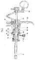
- the endoscopic instrument shown in FIG. 1 is a resectoscope with a distal-side hollow shaft 2, at the proximal end of which a connection part 4 is arranged.
- the connecting part 4 has both a line connection 6 for introducing a rinsing liquid into the hollow shaft 2 and a line connection 8 for sucking the rinsing liquid out of the hollow shaft 2.
- a slide valve 10 arranged in the connection part 4 either the line connection 6 or the line connection 8 can be closed or released. Closes in a middle position the slide valve 10, both the line connection 6 and the line connection 8.
- the slide valve 10 has a rotary valve 12 which is rotatable about a longitudinal axis of the hollow shaft 2 by means of a lever 14 that in a first position of the rotary valve 12 of the terminal. 6 released and the terminal 8 is closed and closed in a second position, the terminal 6 and the terminal 8 is released.
- a coupling part 16 connects to the connection part 4.
- this coupling part 16 is a known per se and therefore not described here in detail work insert 18, in which a not shown optics and an HF cutting sling are performed.
- the proximal end of the cutting loop is fixed in a lock body 24, which also carries the electrical connection contact 31.
- the lock body 24 handles 26 and 28, the cutting loop can be moved in the longitudinal direction.
- the coupling part 16 has a complementary to the contour of the working insert 18 opening 30.
- This aperture 30 has a distal-side opening 32 and a proximal-side opening 34, wherein the opening 34 is arranged eccentrically to the opening 32, that is, only the opening 32 is aligned with the shaft 2.
- a hollow-cylindrical projection 33 is formed at the front side of the essentially cylindrical coupling part 16, on which a shoulder 36 is provided.
- a sealing ring 38 is arranged so that it bears tightly against an end face formed by the shoulder 38 and on the peripheral surface formed by the shoulder.
- the sealing ring 38 is supported by the shoulder 36 both in the radial and in the axial direction and is thus connected in a rotationally fixed manner to the coupling part 16.
- a second shoulder 40 is formed on the outer circumference of the coupling part 16.
- a union nut 44 is rotatably mounted.
- the two-hole nut 42 has an internal thread with which it is screwed onto an external thread, which is arranged on a distal side of the shoulder 40 adjoining peripheral region of the coupling part 16. It has an end face on a stop ring, which is formed so that the union nut 44, when the two-nut 42 is screwed against the shoulder 40, is mounted both radially and axially with little play.
- the union nut 44 is rotatable relative to the coupling part 16 and forms both an axial and a radial bearing for the coupling part sixteenth
- the coupling part 16 with the connection part 4 is connectable.
- the connecting part 4 at its proximal end on the circumference of an external thread 46, on which the union nut 44 is screwed.
- an annular shoulder 48 is provided in order to deliver the coupling part 16 to the connection part 4 only so far that the coupling part 16 rests liquid-tight on the connection part 4, but the coupling part 16 remains rotatable relative to the connection part 4 and the shaft 2 arranged thereon, on the outer circumference of the connection part 4 on the distal side.
- the shoulder 48 forms a stop against which the union nut can be screwed to the external thread 46, so that the coupling part is freely rotatable.
- a coupling 52 is arranged on the proximal side, which serves for securing the working insert 18 in the coupling part 16.
- the clutch 52 is formed as known couplings of this type and therefore not described in detail here.
Abstract
Description
Die Erfindung betrifft ein endoskopisches Instrument mit den im Oberbegriff des Anspruchs 1 angegebenen Merkmalen.The invention relates to an endoscopic instrument having the features specified in the preamble of claim 1.
Endoskopische Instrumente, wie sie beispielsweise zur Resektoskopie eingesetzt werden, weisen im Allgemeinen einen Schaft auf, durch den Arbeitsgeräte typischerweise in Form eines Arbeitseinsatzes geführt werden, die proximalseitig an dem Schaft angebunden werden. Über entsprechende Anschlüsse wird bei diesen Instrumenten eine Spülflüssigkeit in den Schaft eingeleitet, dem Operationsgebiet zugeführt und anschließend zusammen mit Geweberesten wieder abgesaugt.Endoscopic instruments, such as those used for resectoscopy, generally have a shaft through which work implements are typically guided in the form of a working insert, which are tied to the proximal end of the shaft. By means of appropriate connections, a rinsing fluid is introduced into the shaft in these instruments, supplied to the operating area and then sucked off again together with tissue residues.
Generell unterscheidet man bei derartigen endoskopischen Instrumenten solche mit einer fortwährenden Spülung von Instrumenten mit intermittierender Spülung.In general, such endoscopic instruments are distinguished from those with a continuous irrigation of instruments with intermittent irrigation.
Die Schäfte der Instrumente mit einer fortwährenden Spülung sind doppelwandig ausgebildet und werden als sogenannte "Continuos-Flow"-Schäfte bezeichnet. Bei diesen Schäften wird dem Operationsgebiet fortwährend über ein inneres Schaftrohr Spülflüssigkeit zugeführt, während Spülflüssigkeit gleichzeitig über einen von dem inneren und einem äußeren Schaftrohr gebildeten Ringspalt wieder abgesaugt wird. Es ist bekannt, endoskopische Instrumente mit einem "Continuos-Flow"-Schaft so auszubilden, dass ein in dem inneren Schaftrohr geführter Arbeitseinsatz zusammen mit dem inneren Schaftrohr drehbar ist, während das äußere Schaftrohr nicht verdreht wird. Dies ist vorteilhaft, da ein Verdrehen des Außenschaftes das ihn umgebende Gewebe traumatisieren könnte. Nachteilig steht dem aber gegenüber, dass der Außendurchmesser der "Continuos-Flow"-Schäfte konstruktionsbedingt sehr groß ist und das den Schaft umgebende Körpergewebe auf andere Weise belastet.The shafts of the instruments with a continuous flush are double-walled and are referred to as so-called "continuos flow" shafts. In these shafts, irrigating fluid is continuously supplied to the operating area via an inner shaft tube, while irrigation fluid is sucked out again at the same time via an annular gap formed by the inner and an outer shaft tube. It is known to form endoscopic instruments with a "continuos flow" shaft such that a working insert guided in the inner shaft tube is rotatable together with the inner shaft tube, while the outer shaft tube is not twisted. This is advantageous because a twisting of the outer shaft traumatize the surrounding tissue could. The disadvantage, however, is that the outer diameter of the "continuos flow" shafts by design is very large and the body tissue surrounding the shaft loaded in a different way.
Diesen Nachteil weisen endoskopische Instrumente mit intermittierender Spülung, bei denen eine gleich große Schlinge zum Abtragen von Gewebe wie bei den "Continuos-Flow"-Schäften eingesetzt wird, nicht auf. Solche Instrumente haben einen einfachen Hohlschaft, so dass der Außendurchmesser deutlich kleiner als bei "Continuos-Flow"-Schäften ausgebildet sein kann. Nachteilig ist bei diesen Instrumenten wiederum, dass der Arbeitseinsatz nur zusammen mit dem Schaft verdreht werden kann.This disadvantage is not endoscopic instruments with intermittent irrigation, in which an equal loop for the removal of tissue as in the "continuos flow" shafts is used, not on. Such instruments have a simple hollow shaft, so that the outer diameter can be formed significantly smaller than in "continuos flow" shafts. A disadvantage of these instruments, in turn, that the labor input can only be rotated together with the shaft.
Diesen Nachteil suchen bekannte endoskopische Instrumente mit intermittierender Spülung zu vermeiden, bei denen der Arbeitseinsatz in Verbindung mit dem Hohlschaft drehbar ist und die Leitungsanschlüsse mit den daran angebundenen Schläuchen bei einer Drehung des Arbeitseinsatzes stehen bleiben. Eine Traumatisierung des Gewebes, beispielsweise einer Harnröhre, wird damit jedoch nicht reduziert wie gewünscht.This disadvantage seeks to avoid known endoscopic instruments with intermittent flushing, in which the working insert is rotatable in connection with the hollow shaft and the line connections with the tubes connected thereto remain at a rotation of the working insert. However, traumatization of the tissue, such as a urethra, is not reduced as desired.
Vor diesem Hintergrund liegt der vorliegenden Erfindung die Aufgabe zugrunde, ein endoskopisches Instrument zu schaffen, welches die oben beschriebenen Nachteile vermeidet und einfach zu reinigen ist.Against this background, the present invention has the object to provide an endoscopic instrument which avoids the disadvantages described above and is easy to clean.
Diese Aufgabe wird durch ein endoskopisches Instrument mit den in Anspruch 1 angegebenen Merkmalen gelöst. Vorteilhafte Weiterbildungen der Erfindung ergeben sich aus den Unteransprüchen der nachfolgenden Beschreibung und den Zeichnungen.This object is achieved by an endoscopic instrument having the features specified in claim 1. Advantageous developments of the invention will become apparent from the dependent claims of the following description and the drawings.
Das erfindungsgemäße endoskopische Instrument ist typischerweise intermittierend spülend ausgebildet. Es weist einen Hohlschaft, der proximalseitig mit einem Anschlussteil mit zumindest einem Saug- und/oder Spülanschluss versehen ist sowie ein Kupplungsteil zum Festlegen eines Arbeitseinsatzes auf, wobei das Kupplungsteil gegenüber dem Anschlussteil drehbar gelagert ist. Des Weiteren weist das Instrument Mittel zur lösbaren Verbindung von Kupplungsteil und Anschlussteil und eine ringförmige Axialdichtung auf, welche zwischen dem Anschlussteil und dem Kupplungsteil angeordnet ist.The endoscopic instrument according to the invention is typically designed to be intermittently rinsing. It has a hollow shaft which is provided on the proximal side with a connection part with at least one suction and / or rinsing connection and a coupling part for fixing a working insert, wherein the coupling part is rotatably mounted relative to the connection part. Furthermore, the instrument has means for releasably connecting the coupling part and the connection part and an annular axial seal which is arranged between the connection part and the coupling part.
Proximalseitig ist an dem Anschlussteil ein Kupplungsteil angeordnet. Das Kupplungsteil dient zum Festlegen des Arbeitseinsatzes, der durch das Schaftrohr geführt wird. Gemäß der Erfindung ist das Kupplungsteil so lösbar mit dem Anschlussteil verbunden, dass das Kupplungsteil gegenüber dem Anschlussteil drehbar ist. Dies ermöglicht ein Verdrehen des Arbeitseinsatzes während eines endoskopischen Eingriffs, ohne dass der Hohlschaft des endoskopischen Instruments mitgedreht wird. Auf diese Weise kann eine Belastung des Patienten, beispielsweise eine Traumatisierung des den Schaft umgebenden Körpergewebes, zu der es bei Drehung des Schaftes kommen kann, verhindert werden. Das Anschlussteil wird bei dem erfindungsgemäßen endoskopischen Instrument bei Drehung des Arbeitseinsatzes nicht mitgedreht, so dass ein Operateur z.B. nicht durch einen sich verdrehenden Schlauch bzw. Schläuche, die an dem Anschluss an dem Anschlussteil angebunden sind, behindert wird. Die lösbare Verbindung von Kupplungsteil und Anschlussteil ermöglicht es ferner, dass das Kupplungsteil beispielsweise zu Reinigungszwecken schnell und einfach von dem Anschlussteil getrennt und später wieder zusammengefügt werden kann.Proximalseitig a coupling part is arranged on the connecting part. The coupling part is used to set the working insert, which is guided by the shaft tube. According to the invention, the coupling part is detachably connected to the connection part such that the coupling part is rotatable relative to the connection part. This allows a rotation of the working insert during an endoscopic procedure, without the hollow shaft of the endoscopic instrument is rotated. In this way, a load on the patient, for example a traumatization of the body tissue surrounding the shaft, which can occur during rotation of the shaft, can be prevented. The connection part is not rotated in the endoscopic instrument according to the invention during rotation of the working insert, so that a surgeon, e.g. not hindered by a twisting hose or tubing connected to the port on the connector. The detachable connection of coupling part and connecting part also makes it possible for the coupling part, for example, to be quickly and easily separated from the connecting part for cleaning purposes and later reassembled.
Über eine ringförmige Axialdichtung wird das Kupplungsteil gegenüber dem Anschlussteil abgedichtet. Die Axialdichtung ist so angeordnet, dass sie an dem Kupplungsteil und an dem Anschlussteil dichtend anliegt. Neben der Axialdichtung werden bei dem erfindungsgemäßen endoskopischen Instrument keine weiteren Dichtungen benötigt, um das Anschlussteil gegenüber dem Kupplungsteil abzudichten. Die Axialdichtung liegt vorzugsweise an einer proximalseitigen Stirnfläche des Anschlussteils und einer distalseitigen Stirnfläche des Kupplungsteils an. Dabei kann die Axialdichtung proximalseitig an dem Anschlussteil angebunden sein und dieses gegen eine sich drehende distale Stirnfläche des Kupplungsteils abdichten.Via an annular axial seal, the coupling part is sealed relative to the connecting part. The axial seal is arranged so that it bears sealingly against the coupling part and the connecting part. In addition to the axial seal no further seals are required in the endoscopic instrument according to the invention in order to seal the connection part with respect to the coupling part. The axial seal preferably bears against a proximal end face of the connection part and a distal end face of the coupling part. In this case, the axial seal can be connected to the connecting part on the proximal side and seal it against a rotating distal end face of the coupling part.
Bevorzugt ist die Axialdichtung distalseitig an dem Kupplungsteil angeordnet, und dreht mit dem Kupplungsteil mit, während sie an einer Stirnfläche des Anschlussteils dichtend anliegt. Wegen der Drehung der Axialdichtung relativ zu dem feststehenden Anschlussteil ist die Axialdichtung vorteilhaft aus einem Material auszubilden, welches neben sehr guten Dichteigenschaften auch einen niedrigen Reibungskoeffizienten aufweist. Vorzugsweise ist die Axialdichtung aus einem elastomeren Kunststoff ausgebildet, es sind aber auch anderen Materialien denkbar, die die oben erwähnten Werkstoffeigenschaften aufweisen.Preferably, the axial seal is arranged distally on the coupling part, and rotates with the coupling part, while it sealingly bears against an end face of the connection part. Because of the rotation of the axial seal relative to the fixed connection part, the axial seal is advantageously made of a material which, in addition to very good sealing properties, also has a low coefficient of friction. Preferably, the axial seal is formed of an elastomeric plastic, but there are also other materials conceivable having the above-mentioned material properties.
Distalseitig weist das Kupplungsteil bevorzugt einen hohlzylindrischen Abschnitt auf, der abgestuft ausgebildet ist. An einer Stirnfläche des abgestuften Teils des hohlzylindrischen Abschnitts wird die Axialdichtung vorteilhafterweise abgestützt. Die Stirnfläche ist ringförmig und wird durch eine an dem distalen Ende des hohlzylindrischen Abschnitts angeordnete Stufung der Außenkontur des Kupplungsteils gebildet. Auf dieser Stirnfläche liegt die Axialdichtung so auf, dass sie sowohl in radialer als auch in axialer Richtung an dem Kupplungsteil festgelegt ist. Die Stirnfläche ist vorteilhaft so weit von dem distalen Ende des Kupplungsteils beabstandet, dass eine an dieser Stirnfläche anliegende Axialdichtung die Stufe und damit das Kupplungsteil in axialer Richtung überragt. Auf diese Weise kann die Axialdichtung, wenn das Kupplungsteil an dem Anschlussteil angebunden ist, zwischen der Stirnfläche des Hohlzylindrischen Abschnitts und einer Stirnfläche am Anschlussteil dichtend eingespannt werden und das Kupplungsteil gegenüber dem Anschlussteil abgedichtet werden. Des Weiteren hat diese Anordnung den Vorteil, dass die Axialdichtung in einfacher Weise nach Lösen des Kupplungsteils ausgetauscht oder zu Reinigungszwecken entfernt und eingebaut werden kann.On the distal side, the coupling part preferably has a hollow-cylindrical section, which is stepped. At an end face of the stepped part of the hollow cylindrical portion, the axial seal is advantageously supported. The end face is annular and is formed by a arranged at the distal end of the hollow cylindrical portion gradation of the outer contour of the coupling part. On this end face the axial seal lies on so that it is fixed both in the radial and in the axial direction of the coupling part. The end face is advantageously spaced so far from the distal end of the coupling part that an axial seal bearing against this end face projects beyond the step and thus the coupling part in the axial direction. In this way, when the coupling part is connected to the connecting part, the axial seal between the end face of the hollow cylindrical Section and an end face are sealingly clamped on the connecting part and the coupling part against the connection part to be sealed. Furthermore, this arrangement has the advantage that the axial seal can be exchanged in a simple manner after loosening the coupling part or removed and installed for cleaning purposes.
In einer vorteilhaften Ausführungsform des erfindungsgemäßen endoskopischen Instruments weist das Anschlussteil ein Schieberventil auf. Dieses verbindet den Hohlschaft wahlweise mit einem Spül- oder einem Saugkanal. In diesem Fall sind an dem Anschlussteil zwei Anschlüsse angeordnet. Dabei wird die proximale Stirnseite des Drehschiebers des Schieberventils gleichzeitig als Anlage- und Dichtfläche für die Axialdichtung genutzt. Der Drehschieber des Schieberventils ist flüssigkeitsdicht so in dem Anschlussteil angeordnet, dass er jeweils nur einen dieser Anschlüsse freigibt, d.h., dass er entweder nur den Spülkanal oder den Saugkanal, die jeweils an einem dieser Anschlüsse angebunden sind mit dem Hohlschaft verbindet. Der Operateur kann durch Betätigen des Schieberventils den Hohlschaft mit dem Spülanschluss verbinden oder mit dem Sauganschluss verbinden. Des Weiteren ist es möglich den Drehschieber in eine neutrale Stellung zu stellen, in der beide Anschlüsse von dem Drehschieber verschlossen werden. Vorzugsweise ist der Drehschieber des Schieberventils so an dem proximalen Ende des Anschlussteils angeordnet, dass er zum Reinigen leicht aus dem Anschlussteil ausgebaut werden kann. Eine proximale Stirnfläche des Drehschiebers kann dann die Anlagefläche für die an dem Kupplungsteil angeordnete Axialfläche bilden, auf der sich die Axialdichtung distalseitig abstützt.In an advantageous embodiment of the endoscopic instrument according to the invention, the connection part has a slide valve. This connects the hollow shaft optionally with a purge or a suction channel. In this case, two terminals are arranged on the connecting part. In this case, the proximal end face of the rotary valve of the slide valve is used simultaneously as an abutment and sealing surface for the axial seal. The rotary valve of the spool valve is liquid-tightly disposed in the connector so as to release only one of these ports at a time, that is, it connects either only the scavenging port or the suction port respectively connected at one of these ports to the hollow shaft. The operator can connect the hollow shaft with the flushing connection or connect it to the suction connection by actuating the slide valve. Furthermore, it is possible to set the rotary valve in a neutral position in which both ports are closed by the rotary valve. Preferably, the rotary valve of the slide valve is arranged at the proximal end of the connecting part, that it can be easily removed from the connecting part for cleaning. A proximal end surface of the rotary valve can then form the contact surface for the arranged on the coupling part axial surface on which the axial seal is supported on the distal side.
Das Kupplungsteil ist vorteilhaft gegenüber den Mitteln zur lösbaren Verbindung des Kupplungsteils an dem Anschlussteil drehbar gelagert. Die Die Verbindungsmittel selbst sind dann drehfest an dem Anschlussteil angebunden.The coupling part is advantageously rotatably mounted relative to the means for releasably connecting the coupling part to the connecting part. The The connecting means themselves are then connected in a rotationally fixed manner to the connection part.
Bevorzugt weisen die Mittel zur lösbaren Verbindung von Kupplungsteil und Anschlussteil eine am Kupplungsteil angeordnete Überwurfmutter und ein am Anschlussteil angeordnetes Außengewinde auf. Die Überwurfmutter und das am Anschlussteil angeordnete Außengewinde sind dann zweckmäßigerweise gegen einen Anschlag derart verschraubbar, dass das Kupplungsteil gegenüber dem Anschlussteil stets frei drehbar ist.Preferably, the means for releasably connecting the coupling part and the connection part have a coupling nut arranged on the coupling nut and an external thread arranged on the connection part. The union nut and the external thread arranged on the connection part are then expediently screwed against a stop in such a way that the coupling part is always freely rotatable relative to the connection part.
Der Anschlag kann sowohl an der Überwurfmutter als auch an dem Anschlussteil angeordnet sein, ist aber vorzugsweise an dem Anschlussteil ausgebildet. Wird die Überwurfmutter an dem Anschlussteil aufgeschraubt, begrenzt der Anschlag den gemeinsamen Gewindegang von Überwurfmutter und Außengewinde derart.The stop can be arranged both on the union nut and on the connection part, but is preferably formed on the connection part. If the union nut is screwed onto the connection part, the stop limits the common thread of union nut and external thread in such a way.
Die Überwurfmutter ist zwischen einer Stirnfläche am Außenumfang des Kupplungsteils und einem an einer Umfangsfläche des hohlzylindrischen Ansatzes des Kupplungsteils angeordneten Fixierring formschlüssig gehalten. Die Überwurfmutter, die den Außenumfang des Kupplungsteils im Bereich des hohlzylindrischen Ansatzes mit geringem Spiel übergreift, ist derart an dem Kupplungsteil angebunden, dass das Kupplungsteil gegenüber der Überwurfmutter drehbar, jedoch formschlüssig auf diesem gehalten ist. Da die Überwurfmutter ohnehin drehbar sein muss, ist es besonders günstig hier auch die drehbare Lagerung zwischen Kupplungsteil und Anschlussteil vorzusehen.The union nut is held positively between an end face on the outer circumference of the coupling part and a fixing ring arranged on a peripheral surface of the hollow cylindrical projection of the coupling part. The union nut, which engages over the outer circumference of the coupling part in the region of the hollow cylindrical projection with little play, is connected to the coupling part in such a manner that the coupling part is rotatable relative to the union nut, but held in a form-fitting manner on it. Since the nut must be rotatable anyway, it is particularly favorable here to provide the rotatable mounting between the coupling part and connector.
Die Stirnfläche am Außenumfang des Kupplungsteils kann vorteilhaft durch einen Absatz an der Außenseite des Kupplungsteils ausgebildet sein, der der Überwurfmutter an dem Kupplungsteil eine proximalseitige Auflagefläche bietet und somit das Axiallager zur Aufnahme von Kräften in proximaler Richtung bilden. An der distalseitigen Stirnfläche der Überwurfmutter ist der Fixierring mit geringem axialem Spiel auf dem Kupplungsteil an der Umfangsfläche des hohlzylindrischen Ansatzes drehbar gelagert.The end face on the outer circumference of the coupling part can be advantageously formed by a shoulder on the outside of the coupling part, which offers the coupling nut on the coupling part a proximal-side bearing surface and thus the thrust bearing for receiving forces form in the proximal direction. At the distal end face of the union nut, the fixing ring is rotatably mounted on the coupling part on the peripheral surface of the hollow cylindrical projection with little axial clearance.
Zur Befestigung des Fixierrings an der Umfangsfläche des hohlzylindrischen Ansatzes weist der Fixierring vorteilhaft ein Innengewinde auf, mit dem er in ein Außengewinde, welches an einer Umfangsfläche des hohlzylindrischen Ansatzes des Kupplungsteils vorgesehen ist, eingreift. Dies ermöglicht ein leichtes Anbringen der Überwurfmutter an dem Kupplungsteil. Der Fixierring bildet dabei einen Anschlag, der das Lagerspiel festlegt, mit dem die Überwurfmutter am Kupplungsteil drehbar gelagert ist.For fixing the fixing ring on the peripheral surface of the hollow cylindrical projection, the fixing ring advantageously has an internal thread, with which it engages in an external thread, which is provided on a peripheral surface of the hollow cylindrical projection of the coupling part. This allows easy attachment of the union nut on the coupling part. The fixing ring forms a stop which determines the bearing clearance with which the union nut is rotatably mounted on the coupling part.
In einer vorteilhaften Ausführungsform der Erfindung fluchten der Hohlschaft des endoskopischen Instruments und die dem Hohlschaft zugewandte distalseitige Öffnung des Kupplungsteils, wobei die proximalseitige Öffnung des Kupplungsteils, exzentrisch zu der distalseitigen Öffnung angeordnet ist. Diese Ausführungsform ist vorzugsweise für den Einsatz solcher Arbeitseinsätze vorgesehen, welche bezogen auf eine gemeinsame Längsachse nicht über die gesamte Länge rotationssymmetrisch sind. Diese Arbeistseinsätze weisen beispielsweise einen Abschnitt auf, an dem sie an dem Kupplungsteil festgelegt sind, der exzentrisch zu dem Abschnitt des Arbeitsabschnitts ausgerichtet ist, der in dem Hohlschaft geführt wird. Des Weiteren weisen solche Arbeitseinsätze in diesen Abschnitten unterschiedliche Durchmesser auf. Korrespondierend zu der Form dieser Arbeitseinsätze ist das Kupplungsteil gestaltet, so dass bei dem endoskopischen Instrument nur die für dieses Instrument vorgesehenen Arbeitseinsätze eingesetzt werden können. Um trotzt der Exzentrizität der Arbeitseinsätze diese mit dem Kupplungsteil gegenüber dem Anschlussteil bzw. gegenüber dem Hohlschaft verdrehen zu können, ist es vorgesehen, dass der Hohlschaft und die dem Hohlschaft zugewandte distalseitige Öffnung des Kupplungsteils fluchten, d.h., eine gemeinsame Mittelachse aufweisen.In an advantageous embodiment of the invention, the hollow shaft of the endoscopic instrument and the hollow shaft facing distal-side opening of the coupling part, wherein the proximal-side opening of the coupling part, is arranged eccentrically to the distal-side opening. This embodiment is preferably provided for the use of such work inserts, which are not rotationally symmetrical with respect to a common longitudinal axis over the entire length. These work inserts have, for example, a portion where they are fixed to the coupling part, which is aligned eccentrically to the portion of the working portion, which is guided in the hollow shaft. Furthermore, such work inserts have different diameters in these sections. Corresponding to the shape of these work inserts, the coupling part is designed so that in the endoscopic instrument only provided for this instrument work inserts can be used. To defy the eccentricity of the work inserts this to rotate with the coupling part relative to the connector part or against the hollow shaft, it is provided that the hollow shaft and the Hollow shaft facing distal opening of the coupling part are aligned, ie, have a common center axis.
Es sei an dieser Stelle darauf hingewiesen, dass das erfindungsgemäße Kupplungsteil nicht nur bei endoskopischen Instrumenten mit einem einfachen Hohlschaft, sondern auch bei solchen Instrumenten eingesetzt werden kann, die fortwährend gespült werden und demgemäß einen doppelwandigen "Continuos-Flow"-Schaft aufweisen, so dass diese Instrumente dann auch von dem geringen Reinigungs- und Wartungsaufwand, den das Kupplungsteil erfordert, profitieren.It should be noted at this point that the coupling part according to the invention can be used not only in endoscopic instruments with a simple hollow shaft, but also in those instruments that are continuously flushed and thus have a double-walled "continuos flow" shaft, so that These instruments then also benefit from the low cleaning and maintenance required by the coupling part.
Nachfolgend ist die Erfindung anhand eines in der Zeichnung dargestellten Ausführungsbeispiels erläutert. Es zeigen
- Fig. 1.
- einen Längsschnitt eines erfindungsgemäßen endoskopischen Instruments,
- Fig. 2.
- in vergrößerter Darstellung das Anschlussteil mit daran angeordnetem Kupplungsteil des Instruments nach Fig. 1 und
- Fig. 3.
- das Anschlussteil gemäß Fig.2 in Seitenansicht mit getrennt angeordnetem Kupplungsteil im Schnitt.
- Fig. 1.
- a longitudinal section of an endoscopic instrument according to the invention,
- Fig. 2.
- in an enlarged view of the connecting part with arranged thereon coupling part of the instrument according to Fig. 1 and
- Fig. 3.
- the connection part according to Figure 2 in side view with separately arranged coupling part in section.
Bei dem in Fig. 1 dargestellten endoskopischen Instrument handelt es sich um ein Resektoskop mit einem distalseitigen Hohlschaft 2, an dessen proximalen Ende ein Anschlussteil 4 angeordnet ist. Wie aus Fig. 3 ersichtlich, weist das Anschlussteil 4 sowohl einen Leitungsanschluss 6 zum Einleiten einer Spülflüssigkeit in den Hohlschaft 2 als auch einen Leitungsanschluss 8 zum Absaugen der Spülflüssigkeit aus dem Hohlschaft 2 auf. Mittels eines in dem Anschlussteil 4 angeordneten Schieberventils 10 kann wahlweise der Leitungsanschluss 6 oder der Leitungsanschluss 8 verschlossen oder freigegeben werden. In einer Mittelstellung verschließt das Schieberventil 10 sowohl den Leitungsanschluss 6 als auch den Leitungsanschluss 8. Hierzu weist das Schieberventil 10 einen Drehschieber 12 auf, der mit Hilfe eines Hebels 14 so um die Längsachse des Hohlschafts 2 drehbar ist, dass in einer ersten Stellung des Drehschiebers 12 der Anschluss 6 freigegeben und der Anschluss 8 verschlossen wird und in einer zweiten Stellung der Anschluss 6 verschlossen und der Anschluss 8 freigegeben wird.The endoscopic instrument shown in FIG. 1 is a resectoscope with a distal-side
Proximalseitig schließt sich an das Anschlussteil 4 ein Kupplungsteil 16 an. An diesem Kupplungsteil 16 ist ein an sich bekannter und daher hier nicht im einzelnen beschriebener Arbeitseinsatz 18 festgelegt, in dem eine nicht dargestellte Optik sowie eine HF Schneidschlinge geführt werden. Das proximale Ende der Schneidschlinge ist in einem Schlosskörper 24 festgelegt, welcher auch den elektrischen Anschlusskontakt 31 trägt. Mittels an dem Schlosskörper 24 angeordneten Handhaben 26 und 28 kann die Schneidschlinge in Längsrichtung verfahren werden.On the proximal side, a
Das Kupplungsteil 16 weist eine zu der Kontur des Arbeitseinsatzes 18 komplementäre Durchbrechung 30 auf. Diese Durchbrechung 30 hat eine distalseitge Öffnung 32 und eine proximalseitige Öffnung 34, wobei die Öffnung 34 exzentrisch zur Öffnung 32 angeordnet ist, also nur die Öffnung 32 zum Schaft 2 fluchtet.The
Im Bereich der dem Anschlussteil 4 zugewandten Öffnung 32 ist stirnseitig des im Wesentlichen zylindrischen Kupplungsteils 16 ein hohlzylindrischer Ansatz 33 gebildet, an dem ein Absatz 36 vorgesehen. Auf diesem Absatz 36 ist ein Dichtring 38 so angeordnet, dass er an einer von dem Absatz 38 gebildeten Stirnfläche und an der von dem Absatz gebildeten Umfangsfläche dicht anliegt. Der Dichtring 38 wird so von dem Absatz 36 sowohl in radialer als auch in axialer Richtung abgestützt und ist auf diese Weise drehfest an dem Kupplungsteil 16 angebunden.In the region of the
In proximaler Richtung hinter dem Absatz 36 ist am Außenumfang des Kupplungsteils 16 ein zweiter Absatz 40 gebildet. Zwischen diesem Absatz 40 und einer Zweilochmutter 42, die einen Fixierring bildet, ist eine Überwurfmutter 44 drehbar gelagert. Die Zweilochmutter 42 weist ein Innengewinde auf, mit dem sie auf einem Außengewinde verschraubt, welches an einem distalseitig des Absatzes 40 anschließenden Umfangsbereich des Kupplungsteils 16 angeordnet ist. Sie weist stirnseitig einen Anschlagring auf, der so ausgebildet ist, das die Überwurfmutter 44, wenn die Zweilochmutter 42 gegen den Absatz 40 verschraubt ist, sowohl radial als auch axial mit geringem Spiel gelagert ist. Die Überwurfmutter 44 ist so gegenüber dem Kupplungsteil 16 drehbar und bildet sowohl ein Axial- als auch ein Radiallager für das Kupplungsteil 16.In the proximal direction behind the
Mittels der Überwurfmutter 44 ist das Kupplungsteil 16 mit dem Anschlussteil 4 verbindbar. Hierzu weist das Anschlussteil 4 an seinem proximalen Ende umfangsseitig ein Außengewinde 46 auf, auf dem die Überwurfmutter 44 aufgeschraubt wird. Um das Kupplungsteil 16 dem Anschlussteil 4 nur so weit zuzustellen, dass das Kupplungsteil 16 an dem Anschlussteil 4 flüssigkeitsdicht anliegt, das Kupplungsteil 16 dabei aber drehbar gegenüber dem Anschlussteil 4 und dem daran angeordneten Schaft 2 verbleibt, ist an dem Außenumfang des Anschlussteils 4 distalseitig des Außengewindes 46 ein ringförmiger Absatz 48 vorgesehen. Der Absatz 48 bildet einen Anschlag, gegen den die Überwurfmutter an dem Außengewinde 46 verschraubt werden kann, so dass das Kupplungsteil frei drehbar ist.By means of the
Ist die Überwurfmutter 44 auf dem Außengewinde 46 aufgeschraubt, kontaktiert eine Dichtlippe, die über den gesamten Umfang der dem Anschlussteil 4 zugewandten Stirnfläche des Dichtrings 38 angeordnet ist, eine proximalseitige Stirnfläche 50 des Drehschiebers 12. Auf diese Weise wird das Kupplungsteil 16 gegenüber dem Anschlussteil 4 abgedichtet.If the
An dem Kupplungsteil 16 ist proximalseitig eine Kupplung 52 angeordnet, die zum Befestigen des Arbeitseinsatzes 18 in dem Kupplungsteil 16 dient. Die Kupplung 52 ist wie bekannte Kupplungen dieser Art ausgebildet und daher hier nicht im Einzelnen beschrieben. Mittels der Kupplung wird der Arbeitseinsatz beim Einführen selbsttätig verriegelt, die Verriegelung kann entgegen Federkraft aufgehoben werden, wenn der Arbeitseinsatz entfernt werden soll.On the
- 22
- Hohlschafthollow shaft
- 44
- Anschlussteilconnector
- 66
- Anschlussconnection
- 88th
- Anschlussconnection
- 1010
- Schieberventilspool valve
- 1212
- Drehschieberrotary vane
- 1414
- Betätigungselementactuator
- 1616
- Kupplungsteilcoupling part
- 1818
- Arbeitseinsatzlabor input
- 2424
- Schlosskörperlock body
- 2626
- Handhabungselementhandling element
- 2828
- Handhabungselementhandling element
- 3030
- Durchbrechungperforation
- 3131
- Anschlusskontaktconnection contact
- 3232
- Öffnungopening
- 3333
- Ansatzapproach
- 3434
- Öffnungopening
- 3636
- Absatzparagraph
- 3838
- Dichtringseal
- 4040
- Absatzparagraph
- 4242
- ZweilochmutterSpanner
- 4444
- ÜberwurfmutterNut
- 4646
- Außengewindeexternal thread
- 4848
- Ansatzapproach
- 5050
- Stirnflächeface
- 5252
- Kupplungclutch
Claims (16)
Applications Claiming Priority (1)
| Application Number | Priority Date | Filing Date | Title |
|---|---|---|---|
| DE202004014828U DE202004014828U1 (en) | 2004-09-21 | 2004-09-21 | Endoscopic instrument |
Publications (2)
| Publication Number | Publication Date |
|---|---|
| EP1637065A1 true EP1637065A1 (en) | 2006-03-22 |
| EP1637065B1 EP1637065B1 (en) | 2012-04-11 |
Family
ID=33495460
Family Applications (1)
| Application Number | Title | Priority Date | Filing Date |
|---|---|---|---|
| EP05016840A Active EP1637065B1 (en) | 2004-09-21 | 2005-08-03 | Endoscopic instrument |
Country Status (4)
| Country | Link |
|---|---|
| US (1) | US8118729B2 (en) |
| EP (1) | EP1637065B1 (en) |
| AT (1) | ATE552769T1 (en) |
| DE (1) | DE202004014828U1 (en) |
Families Citing this family (8)
| Publication number | Priority date | Publication date | Assignee | Title |
|---|---|---|---|---|
| DE202004014828U1 (en) | 2004-09-21 | 2004-12-02 | Richard Wolf Gmbh | Endoscopic instrument |
| US7927271B2 (en) * | 2006-05-17 | 2011-04-19 | C.R. Bard, Inc. | Endoscope tool coupling |
| US7905882B1 (en) * | 2007-05-03 | 2011-03-15 | Ellman Alan G | Activator for electrosurgical handpiece |
| DE102008029301A1 (en) * | 2008-06-19 | 2009-12-24 | Richard Wolf Gmbh | Endoscope and shaft system |
| CA2729201C (en) | 2008-06-27 | 2016-06-21 | Davol, Inc. | Endoscopic vacuum controller |
| US9474438B2 (en) * | 2010-05-28 | 2016-10-25 | Gyrus Acmi, Inc. | Continuous flow endoscope systems |
| WO2016040478A1 (en) * | 2014-09-12 | 2016-03-17 | Massachusetts Institute Of Technology | Surgical instruments with selectively rotating handles |
| CA3168809A1 (en) * | 2020-02-04 | 2021-08-12 | Boston Scientific Scimed, Inc. | Rotatable medical device |
Citations (7)
| Publication number | Priority date | Publication date | Assignee | Title |
|---|---|---|---|---|
| US5287845A (en) * | 1991-01-19 | 1994-02-22 | Olympus Winter & Ibe Gmbh | Endoscope for transurethral surgery |
| US5486155A (en) * | 1994-07-15 | 1996-01-23 | Circon Corporation | Rotatable endoscope sheath |
| DE19826311A1 (en) * | 1998-06-12 | 1999-12-23 | Bauer Und Haeselbarth Chirurg | Laser resectoscope ensuring that part coming into contact with urinary tube during operation is neither turned nor displaced |
| DE20004329U1 (en) * | 1999-03-10 | 2000-06-08 | Storz Karl Gmbh & Co Kg | Reed tube instrument, in particular proctoscope |
| US6358200B1 (en) * | 1999-09-01 | 2002-03-19 | Circon Corporation | Continuous flow resectoscope with single tube sheath assembly and rotatable connection |
| DE10138331A1 (en) * | 2001-07-27 | 2003-02-20 | Aesculap Ag & Co Kg | Endoscope with proximal and distal ends has fluid-supply and discharge ducts with connections, and instrument duct |
| DE202004014828U1 (en) * | 2004-09-21 | 2004-12-02 | Richard Wolf Gmbh | Endoscopic instrument |
Family Cites Families (5)
| Publication number | Priority date | Publication date | Assignee | Title |
|---|---|---|---|---|
| DE7107645U (en) * | 1971-03-02 | 1971-05-27 | Storz K | ENDOSCOPE IN PARTICULAR CYSTOSCOPE |
| US5435805A (en) | 1992-08-12 | 1995-07-25 | Vidamed, Inc. | Medical probe device with optical viewing capability |
| US5151101A (en) | 1988-06-02 | 1992-09-29 | Circon Corporation | System for disconnectably mounting an endoscope sheath with an endoscope tool |
| US6808505B2 (en) * | 2000-02-01 | 2004-10-26 | Kadan Jeffrey S | Diagnostic needle arthroscopy and lavage system |
| US20030050603A1 (en) * | 2001-09-12 | 2003-03-13 | Todd Erik F. | Cannula that provides bi-directional fluid flow that is regulated by a single valve |
-
2004
- 2004-09-21 DE DE202004014828U patent/DE202004014828U1/en not_active Expired - Lifetime
-
2005
- 2005-08-03 AT AT05016840T patent/ATE552769T1/en active
- 2005-08-03 EP EP05016840A patent/EP1637065B1/en active Active
- 2005-09-20 US US11/231,172 patent/US8118729B2/en active Active
Patent Citations (7)
| Publication number | Priority date | Publication date | Assignee | Title |
|---|---|---|---|---|
| US5287845A (en) * | 1991-01-19 | 1994-02-22 | Olympus Winter & Ibe Gmbh | Endoscope for transurethral surgery |
| US5486155A (en) * | 1994-07-15 | 1996-01-23 | Circon Corporation | Rotatable endoscope sheath |
| DE19826311A1 (en) * | 1998-06-12 | 1999-12-23 | Bauer Und Haeselbarth Chirurg | Laser resectoscope ensuring that part coming into contact with urinary tube during operation is neither turned nor displaced |
| DE20004329U1 (en) * | 1999-03-10 | 2000-06-08 | Storz Karl Gmbh & Co Kg | Reed tube instrument, in particular proctoscope |
| US6358200B1 (en) * | 1999-09-01 | 2002-03-19 | Circon Corporation | Continuous flow resectoscope with single tube sheath assembly and rotatable connection |
| DE10138331A1 (en) * | 2001-07-27 | 2003-02-20 | Aesculap Ag & Co Kg | Endoscope with proximal and distal ends has fluid-supply and discharge ducts with connections, and instrument duct |
| DE202004014828U1 (en) * | 2004-09-21 | 2004-12-02 | Richard Wolf Gmbh | Endoscopic instrument |
Also Published As
| Publication number | Publication date |
|---|---|
| US8118729B2 (en) | 2012-02-21 |
| US20060063975A1 (en) | 2006-03-23 |
| ATE552769T1 (en) | 2012-04-15 |
| EP1637065B1 (en) | 2012-04-11 |
| DE202004014828U1 (en) | 2004-12-02 |
Similar Documents
| Publication | Publication Date | Title |
|---|---|---|
| EP1523932B1 (en) | Endoscope | |
| EP1637065B1 (en) | Endoscopic instrument | |
| DE60130431T2 (en) | ROTATING MILLING TOOLS WITH SUCTION CHANNELS MILLING TIPS | |
| DE19707373C1 (en) | Releasable connection of two tube shaft instruments or instrument parts | |
| EP0496110B1 (en) | Endoscope for transurethral operation | |
| EP1325704B1 (en) | Hysteroscope with interchangable shafts | |
| EP0671149B1 (en) | Device for placing an anastomosis ring | |
| EP0199848B1 (en) | Device for introducing an endoscope or a surgical instrument into hollow organs with means for supplying and evacuating an irrigating fluid | |
| EP0412282B1 (en) | Endoscope for nasal surgery | |
| EP2135542B1 (en) | Endoscope and shaft system | |
| DE19633124B4 (en) | Scraping or cutting instrument | |
| WO1997018745A2 (en) | Shaving or cutting instrument | |
| DE19521257A1 (en) | Surgical forceps for arthroscope | |
| WO2008101653A2 (en) | Tube assembly for an endoscope | |
| DE19819432C2 (en) | Handpiece for a medical device for suction and rinsing | |
| EP2903494B1 (en) | Disposable endoscopy and biopsy system | |
| EP3015082B1 (en) | Dismountable medical instrument | |
| EP1234548B1 (en) | Medical or dental treatment instrument with a filter element | |
| WO2004032732A1 (en) | Removable resectoscope provided with an external shaft | |
| DE102021108314B4 (en) | Stopcock, stopcock plug and method of manufacturing a stopcock plug | |
| DE102018121660B4 (en) | endoscope connector body | |
| DE3231693C2 (en) | ||
| DE19756629C2 (en) | Instrument, especially trocar or endoscope | |
| DE4402153C1 (en) | Surgical flushing and suction device | |
| DE10138331B4 (en) | endoscope |
Legal Events
| Date | Code | Title | Description |
|---|---|---|---|
| PUAI | Public reference made under article 153(3) epc to a published international application that has entered the european phase |
Free format text: ORIGINAL CODE: 0009012 |
|
| AK | Designated contracting states |
Kind code of ref document: A1 Designated state(s): AT BE BG CH CY CZ DE DK EE ES FI FR GB GR HU IE IS IT LI LT LU LV MC NL PL PT RO SE SI SK TR |
|
| AX | Request for extension of the european patent |
Extension state: AL BA HR MK YU |
|
| 17P | Request for examination filed |
Effective date: 20060908 |
|
| 17Q | First examination report despatched |
Effective date: 20061019 |
|
| AKX | Designation fees paid |
Designated state(s): AT BE BG CH CY CZ DE DK EE ES FI FR GB GR HU IE IS IT LI LT LU LV MC NL PL PT RO SE SI SK TR |
|
| GRAP | Despatch of communication of intention to grant a patent |
Free format text: ORIGINAL CODE: EPIDOSNIGR1 |
|
| GRAS | Grant fee paid |
Free format text: ORIGINAL CODE: EPIDOSNIGR3 |
|
| GRAA | (expected) grant |
Free format text: ORIGINAL CODE: 0009210 |
|
| AK | Designated contracting states |
Kind code of ref document: B1 Designated state(s): AT BE BG CH CY CZ DE DK EE ES FI FR GB GR HU IE IS IT LI LT LU LV MC NL PL PT RO SE SI SK TR |
|
| REG | Reference to a national code |
Ref country code: GB Ref legal event code: FG4D Free format text: NOT ENGLISH |
|
| REG | Reference to a national code |
Ref country code: CH Ref legal event code: EP |
|
| REG | Reference to a national code |
Ref country code: AT Ref legal event code: REF Ref document number: 552769 Country of ref document: AT Kind code of ref document: T Effective date: 20120415 |
|
| REG | Reference to a national code |
Ref country code: IE Ref legal event code: FG4D Free format text: LANGUAGE OF EP DOCUMENT: GERMAN |
|
| REG | Reference to a national code |
Ref country code: DE Ref legal event code: R096 Ref document number: 502005012609 Country of ref document: DE Effective date: 20120606 |
|
| REG | Reference to a national code |
Ref country code: CH Ref legal event code: NV Representative=s name: ISLER & PEDRAZZINI AG |
|
| REG | Reference to a national code |
Ref country code: NL Ref legal event code: T3 |
|
| LTIE | Lt: invalidation of european patent or patent extension |
Effective date: 20120411 |
|
| PG25 | Lapsed in a contracting state [announced via postgrant information from national office to epo] |
Ref country code: LT Free format text: LAPSE BECAUSE OF FAILURE TO SUBMIT A TRANSLATION OF THE DESCRIPTION OR TO PAY THE FEE WITHIN THE PRESCRIBED TIME-LIMIT Effective date: 20120411 Ref country code: IS Free format text: LAPSE BECAUSE OF FAILURE TO SUBMIT A TRANSLATION OF THE DESCRIPTION OR TO PAY THE FEE WITHIN THE PRESCRIBED TIME-LIMIT Effective date: 20120811 Ref country code: PL Free format text: LAPSE BECAUSE OF FAILURE TO SUBMIT A TRANSLATION OF THE DESCRIPTION OR TO PAY THE FEE WITHIN THE PRESCRIBED TIME-LIMIT Effective date: 20120411 Ref country code: CY Free format text: LAPSE BECAUSE OF FAILURE TO SUBMIT A TRANSLATION OF THE DESCRIPTION OR TO PAY THE FEE WITHIN THE PRESCRIBED TIME-LIMIT Effective date: 20120411 Ref country code: FI Free format text: LAPSE BECAUSE OF FAILURE TO SUBMIT A TRANSLATION OF THE DESCRIPTION OR TO PAY THE FEE WITHIN THE PRESCRIBED TIME-LIMIT Effective date: 20120411 Ref country code: SE Free format text: LAPSE BECAUSE OF FAILURE TO SUBMIT A TRANSLATION OF THE DESCRIPTION OR TO PAY THE FEE WITHIN THE PRESCRIBED TIME-LIMIT Effective date: 20120411 |
|
| PG25 | Lapsed in a contracting state [announced via postgrant information from national office to epo] |
Ref country code: LV Free format text: LAPSE BECAUSE OF FAILURE TO SUBMIT A TRANSLATION OF THE DESCRIPTION OR TO PAY THE FEE WITHIN THE PRESCRIBED TIME-LIMIT Effective date: 20120411 Ref country code: PT Free format text: LAPSE BECAUSE OF FAILURE TO SUBMIT A TRANSLATION OF THE DESCRIPTION OR TO PAY THE FEE WITHIN THE PRESCRIBED TIME-LIMIT Effective date: 20120813 Ref country code: GR Free format text: LAPSE BECAUSE OF FAILURE TO SUBMIT A TRANSLATION OF THE DESCRIPTION OR TO PAY THE FEE WITHIN THE PRESCRIBED TIME-LIMIT Effective date: 20120712 Ref country code: SI Free format text: LAPSE BECAUSE OF FAILURE TO SUBMIT A TRANSLATION OF THE DESCRIPTION OR TO PAY THE FEE WITHIN THE PRESCRIBED TIME-LIMIT Effective date: 20120411 |
|
| PG25 | Lapsed in a contracting state [announced via postgrant information from national office to epo] |
Ref country code: SK Free format text: LAPSE BECAUSE OF FAILURE TO SUBMIT A TRANSLATION OF THE DESCRIPTION OR TO PAY THE FEE WITHIN THE PRESCRIBED TIME-LIMIT Effective date: 20120411 Ref country code: CZ Free format text: LAPSE BECAUSE OF FAILURE TO SUBMIT A TRANSLATION OF THE DESCRIPTION OR TO PAY THE FEE WITHIN THE PRESCRIBED TIME-LIMIT Effective date: 20120411 Ref country code: EE Free format text: LAPSE BECAUSE OF FAILURE TO SUBMIT A TRANSLATION OF THE DESCRIPTION OR TO PAY THE FEE WITHIN THE PRESCRIBED TIME-LIMIT Effective date: 20120411 Ref country code: DK Free format text: LAPSE BECAUSE OF FAILURE TO SUBMIT A TRANSLATION OF THE DESCRIPTION OR TO PAY THE FEE WITHIN THE PRESCRIBED TIME-LIMIT Effective date: 20120411 Ref country code: RO Free format text: LAPSE BECAUSE OF FAILURE TO SUBMIT A TRANSLATION OF THE DESCRIPTION OR TO PAY THE FEE WITHIN THE PRESCRIBED TIME-LIMIT Effective date: 20120411 |
|
| PLBE | No opposition filed within time limit |
Free format text: ORIGINAL CODE: 0009261 |
|
| STAA | Information on the status of an ep patent application or granted ep patent |
Free format text: STATUS: NO OPPOSITION FILED WITHIN TIME LIMIT |
|
| PG25 | Lapsed in a contracting state [announced via postgrant information from national office to epo] |
Ref country code: IT Free format text: LAPSE BECAUSE OF FAILURE TO SUBMIT A TRANSLATION OF THE DESCRIPTION OR TO PAY THE FEE WITHIN THE PRESCRIBED TIME-LIMIT Effective date: 20120411 |
|
| 26N | No opposition filed |
Effective date: 20130114 |
|
| PG25 | Lapsed in a contracting state [announced via postgrant information from national office to epo] |
Ref country code: MC Free format text: LAPSE BECAUSE OF NON-PAYMENT OF DUE FEES Effective date: 20120831 |
|
| PG25 | Lapsed in a contracting state [announced via postgrant information from national office to epo] |
Ref country code: ES Free format text: LAPSE BECAUSE OF FAILURE TO SUBMIT A TRANSLATION OF THE DESCRIPTION OR TO PAY THE FEE WITHIN THE PRESCRIBED TIME-LIMIT Effective date: 20120722 |
|
| REG | Reference to a national code |
Ref country code: DE Ref legal event code: R097 Ref document number: 502005012609 Country of ref document: DE Effective date: 20130114 |
|
| REG | Reference to a national code |
Ref country code: IE Ref legal event code: MM4A |
|
| PG25 | Lapsed in a contracting state [announced via postgrant information from national office to epo] |
Ref country code: BG Free format text: LAPSE BECAUSE OF FAILURE TO SUBMIT A TRANSLATION OF THE DESCRIPTION OR TO PAY THE FEE WITHIN THE PRESCRIBED TIME-LIMIT Effective date: 20120711 Ref country code: IE Free format text: LAPSE BECAUSE OF NON-PAYMENT OF DUE FEES Effective date: 20120803 |
|
| REG | Reference to a national code |
Ref country code: AT Ref legal event code: MM01 Ref document number: 552769 Country of ref document: AT Kind code of ref document: T Effective date: 20120831 |
|
| PG25 | Lapsed in a contracting state [announced via postgrant information from national office to epo] |
Ref country code: AT Free format text: LAPSE BECAUSE OF NON-PAYMENT OF DUE FEES Effective date: 20120831 |
|
| PG25 | Lapsed in a contracting state [announced via postgrant information from national office to epo] |
Ref country code: TR Free format text: LAPSE BECAUSE OF FAILURE TO SUBMIT A TRANSLATION OF THE DESCRIPTION OR TO PAY THE FEE WITHIN THE PRESCRIBED TIME-LIMIT Effective date: 20120411 |
|
| PG25 | Lapsed in a contracting state [announced via postgrant information from national office to epo] |
Ref country code: HU Free format text: LAPSE BECAUSE OF FAILURE TO SUBMIT A TRANSLATION OF THE DESCRIPTION OR TO PAY THE FEE WITHIN THE PRESCRIBED TIME-LIMIT Effective date: 20050803 |
|
| REG | Reference to a national code |
Ref country code: FR Ref legal event code: PLFP Year of fee payment: 12 |
|
| REG | Reference to a national code |
Ref country code: FR Ref legal event code: PLFP Year of fee payment: 13 |
|
| REG | Reference to a national code |
Ref country code: FR Ref legal event code: PLFP Year of fee payment: 14 |
|
| PGFP | Annual fee paid to national office [announced via postgrant information from national office to epo] |
Ref country code: NL Payment date: 20200819 Year of fee payment: 16 |
|
| PGFP | Annual fee paid to national office [announced via postgrant information from national office to epo] |
Ref country code: LU Payment date: 20200819 Year of fee payment: 16 Ref country code: GB Payment date: 20200824 Year of fee payment: 16 |
|
| PGFP | Annual fee paid to national office [announced via postgrant information from national office to epo] |
Ref country code: CH Payment date: 20200825 Year of fee payment: 16 Ref country code: BE Payment date: 20200818 Year of fee payment: 16 |
|
| REG | Reference to a national code |
Ref country code: DE Ref legal event code: R084 Ref document number: 502005012609 Country of ref document: DE |
|
| REG | Reference to a national code |
Ref country code: CH Ref legal event code: PL |
|
| REG | Reference to a national code |
Ref country code: NL Ref legal event code: MM Effective date: 20210901 |
|
| REG | Reference to a national code |
Ref country code: BE Ref legal event code: MM Effective date: 20210831 |
|
| GBPC | Gb: european patent ceased through non-payment of renewal fee |
Effective date: 20210803 |
|
| PG25 | Lapsed in a contracting state [announced via postgrant information from national office to epo] |
Ref country code: LI Free format text: LAPSE BECAUSE OF NON-PAYMENT OF DUE FEES Effective date: 20210831 Ref country code: CH Free format text: LAPSE BECAUSE OF NON-PAYMENT OF DUE FEES Effective date: 20210831 |
|
| PG25 | Lapsed in a contracting state [announced via postgrant information from national office to epo] |
Ref country code: LU Free format text: LAPSE BECAUSE OF NON-PAYMENT OF DUE FEES Effective date: 20210803 |
|
| PG25 | Lapsed in a contracting state [announced via postgrant information from national office to epo] |
Ref country code: NL Free format text: LAPSE BECAUSE OF NON-PAYMENT OF DUE FEES Effective date: 20210901 |
|
| PG25 | Lapsed in a contracting state [announced via postgrant information from national office to epo] |
Ref country code: GB Free format text: LAPSE BECAUSE OF NON-PAYMENT OF DUE FEES Effective date: 20210803 Ref country code: BE Free format text: LAPSE BECAUSE OF NON-PAYMENT OF DUE FEES Effective date: 20210831 |
|
| PGFP | Annual fee paid to national office [announced via postgrant information from national office to epo] |
Ref country code: FR Payment date: 20230821 Year of fee payment: 19 Ref country code: DE Payment date: 20230821 Year of fee payment: 19 |