EP1637741A1 - Liquid cooled pump and pump controller - Google Patents
Liquid cooled pump and pump controller Download PDFInfo
- Publication number
- EP1637741A1 EP1637741A1 EP04450177A EP04450177A EP1637741A1 EP 1637741 A1 EP1637741 A1 EP 1637741A1 EP 04450177 A EP04450177 A EP 04450177A EP 04450177 A EP04450177 A EP 04450177A EP 1637741 A1 EP1637741 A1 EP 1637741A1
- Authority
- EP
- European Patent Office
- Prior art keywords
- pump
- liquid
- housing
- control device
- pump control
- Prior art date
- Legal status (The legal status is an assumption and is not a legal conclusion. Google has not performed a legal analysis and makes no representation as to the accuracy of the status listed.)
- Withdrawn
Links
- 239000007788 liquid Substances 0.000 title claims description 56
- 239000012530 fluid Substances 0.000 claims abstract description 25
- 229910001369 Brass Inorganic materials 0.000 claims description 3
- 239000010951 brass Substances 0.000 claims description 3
- 239000002184 metal Substances 0.000 claims description 3
- 229910001092 metal group alloy Inorganic materials 0.000 claims description 3
- 238000001816 cooling Methods 0.000 description 8
- 239000003990 capacitor Substances 0.000 description 3
- 238000005266 casting Methods 0.000 description 2
- 238000010276 construction Methods 0.000 description 2
- 238000004519 manufacturing process Methods 0.000 description 2
- 238000004140 cleaning Methods 0.000 description 1
- 238000004891 communication Methods 0.000 description 1
- 230000005494 condensation Effects 0.000 description 1
- 238000009833 condensation Methods 0.000 description 1
- 239000004020 conductor Substances 0.000 description 1
- 239000004519 grease Substances 0.000 description 1
- 239000011796 hollow space material Substances 0.000 description 1
- 238000009434 installation Methods 0.000 description 1
- 230000002452 interceptive effect Effects 0.000 description 1
- 239000000463 material Substances 0.000 description 1
- 238000012544 monitoring process Methods 0.000 description 1
- 238000013021 overheating Methods 0.000 description 1
- 230000001376 precipitating effect Effects 0.000 description 1
- 238000005086 pumping Methods 0.000 description 1
- 238000009420 retrofitting Methods 0.000 description 1
- 238000000926 separation method Methods 0.000 description 1
- 239000007787 solid Substances 0.000 description 1
- 238000012546 transfer Methods 0.000 description 1
- 238000011144 upstream manufacturing Methods 0.000 description 1
- XLYOFNOQVPJJNP-UHFFFAOYSA-N water Substances O XLYOFNOQVPJJNP-UHFFFAOYSA-N 0.000 description 1
Images


Classifications
-
- F—MECHANICAL ENGINEERING; LIGHTING; HEATING; WEAPONS; BLASTING
- F04—POSITIVE - DISPLACEMENT MACHINES FOR LIQUIDS; PUMPS FOR LIQUIDS OR ELASTIC FLUIDS
- F04D—NON-POSITIVE-DISPLACEMENT PUMPS
- F04D15/00—Control, e.g. regulation, of pumps, pumping installations or systems
- F04D15/0066—Control, e.g. regulation, of pumps, pumping installations or systems by changing the speed, e.g. of the driving engine
-
- F—MECHANICAL ENGINEERING; LIGHTING; HEATING; WEAPONS; BLASTING
- F04—POSITIVE - DISPLACEMENT MACHINES FOR LIQUIDS; PUMPS FOR LIQUIDS OR ELASTIC FLUIDS
- F04B—POSITIVE-DISPLACEMENT MACHINES FOR LIQUIDS; PUMPS
- F04B49/00—Control, e.g. of pump delivery, or pump pressure of, or safety measures for, machines, pumps, or pumping installations, not otherwise provided for, or of interest apart from, groups F04B1/00 - F04B47/00
- F04B49/06—Control using electricity
- F04B49/065—Control using electricity and making use of computers
-
- F—MECHANICAL ENGINEERING; LIGHTING; HEATING; WEAPONS; BLASTING
- F04—POSITIVE - DISPLACEMENT MACHINES FOR LIQUIDS; PUMPS FOR LIQUIDS OR ELASTIC FLUIDS
- F04B—POSITIVE-DISPLACEMENT MACHINES FOR LIQUIDS; PUMPS
- F04B53/00—Component parts, details or accessories not provided for in, or of interest apart from, groups F04B1/00 - F04B23/00 or F04B39/00 - F04B47/00
- F04B53/08—Cooling; Heating; Preventing freezing
-
- F—MECHANICAL ENGINEERING; LIGHTING; HEATING; WEAPONS; BLASTING
- F04—POSITIVE - DISPLACEMENT MACHINES FOR LIQUIDS; PUMPS FOR LIQUIDS OR ELASTIC FLUIDS
- F04D—NON-POSITIVE-DISPLACEMENT PUMPS
- F04D13/00—Pumping installations or systems
- F04D13/02—Units comprising pumps and their driving means
- F04D13/06—Units comprising pumps and their driving means the pump being electrically driven
-
- F—MECHANICAL ENGINEERING; LIGHTING; HEATING; WEAPONS; BLASTING
- F04—POSITIVE - DISPLACEMENT MACHINES FOR LIQUIDS; PUMPS FOR LIQUIDS OR ELASTIC FLUIDS
- F04D—NON-POSITIVE-DISPLACEMENT PUMPS
- F04D29/00—Details, component parts, or accessories
- F04D29/58—Cooling; Heating; Diminishing heat transfer
- F04D29/5813—Cooling the control unit
Landscapes
- Engineering & Computer Science (AREA)
- Mechanical Engineering (AREA)
- General Engineering & Computer Science (AREA)
- Computer Hardware Design (AREA)
- Physics & Mathematics (AREA)
- Thermal Sciences (AREA)
- Structures Of Non-Positive Displacement Pumps (AREA)
Abstract
Description
Die Erfindung betrifft ein Pumpensteuergerät mit einem Gehäuse und einem in dem Gehäuse angeordneten Drehzahlregler, insbesondere Frequenzumformer, zur Regelung der Drehzahl eines elektrischen Antriebsmotors einer Flüssigkeitspumpe. Weiters betrifft die Erfindung eine Flüssigkeitspumpenanordnung.The invention relates to a pump control device having a housing and a speed controller arranged in the housing, in particular frequency converter, for controlling the rotational speed of an electric drive motor of a liquid pump. Furthermore, the invention relates to a liquid pump arrangement.
Drehzahlregler in Pumpensteuergeräten weisen elektronische Leistungsbauteile auf, die sich im Betrieb stark erwärmen. Um diese Leistungsbauteile vor dem Durchbrennen zu schützen, muss die entstehende Wärme abgeführt werden. Dies erfolgt über Kühlkörper mit Kühlrippen, Ventilatoren oder dergleichen, um die Wärme durch Konvektion oder einen Zwangsluftstrom an die Umgebung abzugeben. Es sind auch Pumpen bekannt, bei denen der Drehzahlregler flüssigkeitsgekühlt ist.Speed controllers in pump controllers have electronic power components that heat up significantly during operation. To protect these power components from burning through, the resulting heat must be dissipated. This is done via heat sink with cooling fins, fans or the like to deliver the heat by convection or a forced air flow to the environment. Pumps are also known in which the speed controller is liquid-cooled.
So ist aus der DE 196 39 098 A1 eine Motorpumpe mit einem gekühlten Frequenzumformer und einem Elektromotor bekannt, wobei der Frequenzumformer als Wärmesenke eine Platte aufweist, auf der mindestens ein Wärme erzeugendes Elektronikbauteil befestigt ist, wobei die Platte insbesondere senkrecht zur Motorendrehachse liegt und von einem abgezweigten Teil des Fördermediums kühlbar ist.Thus, from DE 196 39 098 A1 a motor pump with a cooled frequency converter and an electric motor is known, wherein the frequency converter has a plate as a heat sink, on which at least one heat generating electronic component is attached, the plate is in particular perpendicular to the engine rotational axis and of a diverted part of the pumped medium is coolable.
Aus der EP 0 520 333 A1 ist wiederum ein Pumpenaggregat bekannt, das einen von einem Teilstrom der Förderflüssigkeit gekühlten Elektromotor mit gegenüber der Förderflüssigkeit abgedichtetem Rotor aufweist. Der Elektromotor treibt eine Kreiselpumpe. Dem Elektromotor vorgeschaltet ist ein Frequenzumformer zur Drehzahlsteuerung des Pumpenaggregats. Der zur Kühlung des Elektromotors und des Frequenzumformers abgezweigte Teilstrom der Förderflüssigkeit durchströmt einen Kühlmantel, der den Motor umfangsseitig umschließt. An der Außenseite dieses Kühlmantels ist der Frequenzumformer wärmeleitend angebracht, der mit dem Motor in einem gemeinsamen Gehäuse angeordnet ist.From EP 0 520 333 A1, in turn, a pump unit is known which has an electric motor cooled by a partial flow of the conveying fluid with a rotor sealed with respect to the conveying fluid. The electric motor drives a centrifugal pump. Upstream of the electric motor is a frequency converter for controlling the speed of the pump unit. The diverted to cool the electric motor and the frequency converter partial flow of the pumped liquid flows through a cooling jacket, which encloses the motor circumferentially. On the outside of this cooling jacket of the frequency converter is mounted heat-conducting, which is arranged with the motor in a common housing.
Nachteilig an diesen bekannten Pumpen mit flüssigkeitsgekühltem Frequenzumformer ist zum einen ihr mechanisch komplizierter Aufbau, der aufwändige Gehäuse- und Rohrleitungskonstruktionen verlangt, um den erwünschten Teilstrom aus der Förderflüssigkeit abzuzweigen, zur Wärmesenke des Frequenzumformers hin und wieder weg zu führen. Ein besonderes Problem besteht dann, wenn in der Förderflüssigkeit Fremdkörper enthalten sind, die sich in den engen Rohrleitungen hin zur Wärmesenke bzw. in den in der Wärmesenke ausgebildeten Kanälen leicht anlegen und diese somit verstopfen können. Die Reinigung der Teilstrom-Rohrleitungen erfordert ein arbeitsaufwändiges Zerlegen der Pumpe. Zudem besteht die Gefahr, dass das Verstopfen der Leitungen zur Förderung des Teilstroms zur Wärmesenke des Frequenzumformer bzw. davon weg nicht rechtzeitig bemerkt wird, da deren Verstopfen die Gesamtförderleistung der Pumpe nicht beeinträchtigt. Es ist somit erforderlich, eine mögliche Überhitzung des Frequenzumformers elektronisch zu überwachen. Weiters ist bei den bekannten Pumpen von Nachteil, dass durch die Verwendung nur eines Teilstroms der Förderflüssigkeit die Kühlleistung eher gering ist, wobei dieser Teilstrom zusätzlich zum Frequenzumformer auch noch den Pumpenmotor kühlen muss. Schließlich stellen die bekannten Pumpen mit flüssigkeitsgekühlten Frequenzumformem Spezialkonstruktionen dar, die für jeden Pumpentyp gesondert zu entwickeln sind. Die nachträgliche Nachrüstung von bestehenden Pumpen ist mit den bekannten Lösungen nicht möglich.A disadvantage of these known pumps with liquid-cooled frequency converter is on the one hand her mechanically complicated structure, the complex housing and Pipe designs required to divert the desired partial flow from the fluid to lead to the heat sink of the frequency converter now and then. A particular problem exists if foreign matter is contained in the delivery fluid, which can easily build up in the narrow conduits towards the heat sink or in the channels formed in the heat sink and thus block them. The cleaning of the partial flow pipelines requires a laborious dismantling of the pump. In addition, there is a risk that the clogging of the lines for conveying the partial flow to the heat sink of the frequency converter or away from it is not noticed in time, as their clogging does not affect the total pumping capacity of the pump. It is thus necessary to electronically monitor possible overheating of the frequency converter. Furthermore, it is disadvantageous in the case of the known pumps that the cooling capacity is rather low as a result of the use of only a partial flow of the delivery fluid, whereby this partial flow must also cool the pump motor in addition to the frequency converter. Finally, the known pumps with liquid-cooled Frequenzumformem represent special designs that are to be developed separately for each type of pump. The subsequent retrofitting of existing pumps is not possible with the known solutions.
Der vorliegenden Erfindung liegt die Aufgabe zugrunde, ein Pumpensteuergerät bereitzustellen, bei dem die geschilderten Probleme des Standes der Technik vermieden werden.The present invention has for its object to provide a pump control device in which the described problems of the prior art are avoided.
Diese Aufgabe wird erfindungsgemäß durch Bereitstellen eines Pumpensteuergeräts mit den Merkmalen des Anspruchs 1 gelöst. Vorteilhafte Ausgestaltungen der Erfindung sind in den Unteransprüchen dargelegt.This object is achieved by providing a pump control device with the features of claim 1. Advantageous embodiments of the invention are set forth in the subclaims.
Das erfindungsgemäße Pumpensteuergerät weist ein Gehäuse auf, in dem ein Drehzahlregler, beispielsweise ein Frequenzumformer, zur Regelung der Drehzahl eines elektrischen Antriebsmotors einer Flüssigkeitspumpe angeordnet ist. Das Gehäuse weist einen Abschnitt mit guter Wärmeleitfähigkeit auf, an dem ein Hohlraum ausgebildet ist, der Anschlüsse zum Verbinden einerseits mit dem Ausgang einer durch das Pumpensteuergerät zu regelnden Flüssigkeitspumpe und andererseits mit Rohrleitungen aufweist, so dass der Hohlraum mit dem gesamten von der Flüssigkeitspumpe geförderten Flüssigkeitsstrom durchströmbar ist, wobei der Drehzahlregler wärmeleitend mit dem Gehäuseabschnitt mit guter Wärmeleitfähigkeit verbunden ist, d.h. der Gehäuseabschnitt mit guter Wärmeleitfähigkeit dient als Wärmesenke für den Drehzahlregler.The pump control device according to the invention has a housing in which a speed controller, for example a frequency converter, for controlling the speed of an electric drive motor of a fluid pump is arranged. The housing has a section with good thermal conductivity, on which a cavity is formed, which has connections for connecting, on the one hand, to the outlet of a fluid pump to be controlled by the pump control device and, on the other hand, with pipelines, so that the Cavity with the entire funded by the liquid pump fluid flow can be flowed through, wherein the speed controller is thermally conductively connected to the housing portion with good thermal conductivity, ie the housing portion with good thermal conductivity serves as a heat sink for the speed controller.
Die Vorteile des erfindungsgemäßen Pumpensteuergerätes sind mannigfaltig. Hervorzuheben ist seine Vielseitigkeit, da es mit bestehenden handelsüblichen, ungeregelten Flüssigkeitspumpen verbunden werden kann, um diesen Pumpen nachträglich Regelungsfunktionen zu verleihen. Die mechanische Konstruktion des erfindungsgemäßen Pumpensteuergeräts ist einfach, solide und robust, so dass es auch in rauen Betriebsumgebungen verlässlich einsetzbar ist. Besonders hervorzuheben ist auch die hohe Kühlleistung des erfindungsgemäßen Pumpensteuergeräts, da der gesamte geförderte Flüssigkeitsstrom einer vom Pumpensteuergerät geregelten Pumpe zur Kühlung des Drehzahlreglers verwendet wird. Somit bestehen unter allen Betriebsbedingungen ausreichende Kühlleistungsreserven, und es kann eine elektronische Überwachung der Temperatur im Pumpensteuergerät entfallen. Das erfindungsgemäße Pumpensteuergerät ist wartungsfrei und unempfindlich gegenüber Verstopfung durch Fremdkörper im Pumpenförderstrom, da durch Verwendung des Gesamtstroms an Förderflüssigkeit eventuell vorhandene Fremdkörper in der Förderflüssigkeit vom Flüssigkeitsstrom mitgerissen werden und außerdem im Gehäuse des Pumpensteuergerätes keine Engstellen vorhanden sind. Vielmehr sind durch Verwendung des Gesamtstroms an Förderflüssigkeit zur Kühlung des Drehzahlreglers der Hohlraum des Gehäuseabschnitts und die Anschlüsse so groß dimensioniert, dass ihre Verstopfung durch Fremdkörper äußerst unwahrscheinlich ist. Es sei erwähnt, dass die Förderflüssigkeit unter dem vollen Pumpendruck durch das Gehäuse des Pumpensteuergerätes gepresst wird. Das Installieren des erfindungsgemäßen Pumpensteuergerätes an einer Pumpe bzw. das Abnehmen von der Pumpe kann mit wenigen Handgriffen erfolgen und erfordert weder Spezialwerkzeug noch besondere Kenntnisse.The advantages of the pump control device according to the invention are manifold. It should be emphasized its versatility, as it can be connected to existing commercial, unregulated liquid pumps to give these pumps subsequent control functions. The mechanical construction of the pump control device according to the invention is simple, solid and robust, so that it can be used reliably even in harsh operating environments. Particularly noteworthy is also the high cooling capacity of the pump control device according to the invention, since the entire funded liquid flow of a pump controlled by the pump control unit is used to cool the speed controller. Thus, under all operating conditions sufficient cooling power reserves, and it can account for an electronic monitoring of the temperature in the pump control unit. The pump control device according to the invention is maintenance-free and insensitive to clogging by foreign bodies in the pump delivery flow, as may be entrained by use of the total flow of fluid possibly present foreign bodies in the fluid from the liquid flow and also in the housing of the pump control unit no bottlenecks are present. Rather, by using the total flow of fluid for cooling the speed controller, the cavity of the housing portion and the connections are dimensioned so large that their clogging by foreign bodies is extremely unlikely. It should be noted that the delivery liquid is forced under the full pump pressure through the housing of the pump control unit. The installation of the pump control unit according to the invention to a pump or the removal of the pump can be done in a few steps and requires no special tools or special knowledge.
In einer Ausgestaltung der Erfindung ist vorgesehen, wärmeerzeugende Bauteile des Drehzahlreglers direkt am Gehäuseabschnitt mit guter Wärmeleitfähigkeit anliegen zu lassen, um die Wärme abzuführen. Es sollte ein möglichst großer Oberflächenabschnitt dieser Bauteile am Gehäuseabschnitt mit guter Wärmeleitfähigkeit anliegen. Alternativ oder ergänzend dazu können wärmeerzeugende Bauteile des Drehzahlreglers über Wärmeleitmittel mit dem Gehäuseabschnitt mit guter Wärmeleitfähigkeit verbunden sein.In one embodiment of the invention, it is provided to leave heat-generating components of the speed controller directly on the housing portion with good thermal conductivity to dissipate the heat. There should be the largest possible surface portion of these components on the housing section with good thermal conductivity. Alternatively or In addition, heat-generating components of the speed controller may be connected via heat conducting means to the housing portion with good thermal conductivity.
Hohe Robustheit und Dichtheit des Pumpensteuergeräts wird erzielt, wenn der Gehäuseabschnitt mit guter Wärmeleitfähigkeit einstückig, vorzugsweise als Gussteil, ausgebildet ist. Aus Gründen der hohen Robustheit sowie guter Wärmeleitfähigkeit ist es bevorzugt, den Gehäuseabschnitt mit guter Wärmeleitfähigkeit aus Metall oder einer Metalllegierung, wie Messing, zu fertigen.High robustness and tightness of the pump control device is achieved when the housing portion with good thermal conductivity in one piece, preferably as a casting is formed. For reasons of high robustness and good thermal conductivity, it is preferable to manufacture the housing section with good thermal conductivity of metal or a metal alloy, such as brass.
Da im Betrieb des Pumpensteuergeräts an einer Pumpe im Hohlraum des Gehäuseabschnitts mit guter Wärmeleitfähigkeit der volle Ausgangsdruck der Pumpe herrscht, kann dieser Druck im Hohlraum vorteilhaft als Ist-Wert zur Pumpenregelung verwendet werden, wozu eine Durchtrittsöffnung in den Hohlraum zum Anschluss eines Sensors vorgesehen ist.Since during operation of the pump control device to a pump in the cavity of the housing portion with good thermal conductivity of the full outlet pressure of the pump prevails, this pressure in the cavity can be advantageously used as an actual value for pump control, including a passage opening is provided in the cavity for connecting a sensor.
Um unterschiedlich große elektronische Bauteile des Drehzahlreglers gleichmäßig gut kühlen zu können, ist in weiterer Ausgestaltung des erfindungsgemäßen Pumpensteuergeräts vorgesehen, dass zur Aufnahme großer Bauteile, wie Elektrolytkondensatoren oder Spulen, im Gehäuseabschnitt Vertiefungen ausgebildet sind, die in den Hohlraum ragen oder an einer Hohlraumwand anliegend angeordnet sind.In order to be able to cool uniformly well different sized electronic components of the speed controller, is provided in a further embodiment of the pump control device that are designed to accommodate large components such as electrolytic capacitors or coils in the housing section recesses which protrude into the cavity or arranged adjacent to a cavity wall are.
Eine besonders einfache und robuste Anschlussmöglichkeit des Pumpensteuergeräts an eine Pumpe bzw. Rohrleitungen ist gegeben, wenn die Anschlüsse des Gehäuseabschnittes mit guter Wärmeleitfähigkeit als Flansche oder Muffen ausgebildet sind.A particularly simple and robust connection possibility of the pump control device to a pump or pipes is given if the connections of the housing section are formed with good thermal conductivity as flanges or sleeves.
Pumpensteuergeräte werden meist in feuchten Umgebungen verwendet. Um zu verhindern, dass sich im Gehäuseinneren Kondenswasser niederschlagen kann, das in weiterer Folge zu einem Ausfall des Drehzahlreglers führen könnte, ist in einer Ausgestaltung des erfindungsgemäßen Pumpensteuergerätes vorgesehen, dass der Gehäuseabschnitt mit guter Wärmeleitfähigkeit als Gehäuseboden ausgebildet ist, der mit einem Gehäusedeckel flüssigkeitsdicht verbindbar ist. Somit kann auch hohe Luftfeuchtigkeit nicht zu Kondenswasserbildung im Gehäuseinneren führen.Pump controllers are mostly used in humid environments. In order to prevent condensate water from precipitating inside the housing, which could subsequently lead to a failure of the speed controller, in an embodiment of the pump control device according to the invention, the housing section with good thermal conductivity is designed as a housing bottom, which can be connected to a housing cover in a liquid-tight manner is. Thus, even high humidity can not lead to condensation inside the housing.
Die Erfindung umfasst weiters eine Flüssigkeitspumpenanordnung mit einer Flüssigkeitspumpe und einem die Flüssigkeitspumpe antreibenden elektrischen Antriebsmotor, wobei an den Ausgang der Flüssigkeitspumpe ein den Antriebsmotor steuerndes erfindungsgemäßes Pumpensteuergerät angeschlossen ist. Es ist aus dem Stand der Technik bekannt, einen Frequenzumrichter entfernt von einem elektrischen Pumpenantriebsmotor anzuordnen und die elektrischen Signale des Frequenzumrichters über Kabel an den elektrischen Antriebsmotor zu übertragen. Dies schafft jedoch Probleme in Bezug auf die elektromagnetische Verträglichkeit (EMV) dieser bekannten Flüssigkeitspumpenanordnung, da durch die im Kilohertzbereich liegenden Steuersignale des Frequenzumrichters, die noch dazu steile Signalflanken aufweisen, elektromagnetische Störsignale abgestrahlt werden. Diesen EMV-Problemen versuchte man durch die Zwischenschaltung von Drosseln und der Verwendung von geschirmten Kabeln zu begegnen, was jedoch zu beträchtlichen elektrischen Verlusten führt, die bei Verwendung von geschirmten Kabeln noch größer sind, da der Kabelschirm zu einer kapazitiven Strombelastung führt. Durch die erfindungsgemäße Maßnahme, ein erfindungsgemäßes Pumpensteuergerät an den Ausgang der Flüssigkeitspumpe anzuschließen, verringert sich die Kabellänge zwischen Pumpensteuergerät und elektrischem Antriebsmotor, über welche die Steuersignale übertragen werden - und damit die Abstrahlung von Störsignalen - auf ein Minimum.The invention further comprises a liquid pump arrangement having a liquid pump and an electric drive motor driving the liquid pump, wherein a pump control device according to the invention controlling the drive motor is connected to the output of the liquid pump. It is known from the prior art to arrange a frequency converter away from an electric pump drive motor and to transmit the electrical signals of the frequency converter via cables to the electric drive motor. However, this creates problems with respect to the electromagnetic compatibility (EMC) of this known fluid pump arrangement, since electromagnetic interference signals are radiated by the kilohertz control signals of the frequency converter, which still have steep signal edges. These EMC problems have been addressed by the interposition of chokes and the use of shielded cables, but this leads to considerable electrical losses, which are even greater when using shielded cables, since the cable shield leads to a capacitive current load. The inventive measure to connect an inventive pump control device to the output of the liquid pump, the cable length between the pump control unit and the electric drive motor, via which the control signals are transmitted - and thus the emission of interfering signals - to a minimum.
In einer zweckmäßigen Fortbildung der erfindungsgemäßen Flüssigkeitspumpenanordnung weist das Pumpensteuergerät ein entferntes Bedienteil auf, das über Steuerleitungen mit dem Pumpensteuergerät kommuniziert. Man erleichtert dadurch die Verwendung der Pumpe für einen Benutzer wesentlich, da die Pumpen meist an schlecht zugänglichen Orten aufgestellt werden müssen oder überhaupt in Brunnen versenkt sind, wogegen das Bedienteil an einer für den Benutzer leicht erreichbaren Stelle montiert werden kann. Lange Kabel zwischen Bedienteil und Pumpensteuergerät stellen dabei kein Problem dar, da die Steuersignale auf diesen Kabeln nur geringe Ströme und niedrige Spannungen aufweisen.In an expedient refinement of the fluid pump arrangement according to the invention, the pump control device has a remote operating part which communicates via control lines with the pump control unit. It facilitates thereby the use of the pump for a user substantially, since the pumps usually have to be installed in hard to reach places or are sunk in wells, whereas the control panel can be mounted in a location easily accessible to the user. Long cables between the control panel and the pump control unit are no problem because the control signals on these cables have only low currents and low voltages.
In einer bevorzugten Ausgestaltung der erfindungsgemäßen Flüssigkeitspumpenanordnung werden die Steuerleitungen zwischen Bedienteil und Pumpensteuergerät auch zur Zufuhr elektrischer Energie zum Pumpensteuergerät und zum elektrischen Antriebsmotor verwendet. Die elektrischen Energieversorgungssignale stellen zwar Signale hoher Leistung dar, sie sind jedoch sinusförmig und weisen die niedrige Netzstromfrequenz von 50 - 60 Hz auf, so dass sie keine nennenswerten Störsignale produzieren. Die Steuersignale können auf einer Trägerfrequenz moduliert den Versorgungssignalen überlagert und im Pumpensteuergerät getrennt werden.In a preferred embodiment of the liquid pump arrangement according to the invention, the control lines between the control unit and the pump control unit also for supplying electrical energy to the pump control unit and the electric drive motor used. Although the electrical power signals represent high power signals, they are sinusoidal and have the low power frequency of 50-60 Hz, so they produce no appreciable noise. The control signals can be modulated on a carrier frequency, superimposed on the supply signals and separated in the pump controller.
In einer besonders bevorzugten Ausführungsform der Flüssigkeitspumpenanordnung ist die Flüssigkeitspumpe als Tauchmotorpumpe ausgebildet. Die Flüssigkeitspumpenanordnung wird dabei in einen Bohrbrunnen eingebracht, wo sie sich in der zu fördernden Flüssigkeit befindet und das erfindungsgemäße Pumpensteuergerät nicht nur durch den Durchfluss des gesamten Flüssigkeits-Förderstroms gekühlt wird, sondern auch von außen durch die im Bohrbrunnen befindliche Flüssigkeit gekühlt wird. Es ist zwar bekannt, einen Frequenzumrichter direkt in einen elektrischen Antriebsmotor einzubauen und in einen Bohrbrunnen einzubringen, dies waren jedoch stets auf den spezifischen Motor abgestimmte Einzelkonstruktionen, die naturgemäß nur in geringen Stückzahlen herstellt wurden und daher entsprechend teuer und unwirtschaftlich waren. Die erfindungsgemäße Lösung erlaubt es jedoch auch, bestehende Tauchmotorpumpen nachzurüsten und somit auf hohe Stückzahlen in der Herstellung zu kommen. Außerdem waren bei den bekannten Antriebsmotoren mit eingebautem Frequenzumrichter stets Teilströme der Flüssigkeit verwendet worden, die irgendwo abgezweigt werden mussten.In a particularly preferred embodiment of the liquid pump arrangement, the liquid pump is designed as a submersible pump. The liquid pump assembly is thereby introduced into a well, where it is located in the liquid to be pumped and the pump control device according to the invention is not only cooled by the flow of the entire liquid flow, but is also cooled from the outside by the liquid located in the well. Although it is known to incorporate a frequency converter directly into an electric drive motor and bring in a well, but these were always tailored to the specific engine individual constructions that were naturally produced only in small quantities and therefore were correspondingly expensive and uneconomical. However, the solution according to the invention also makes it possible to retrofit existing submersible pumps and thus to come to high volumes in the production. In addition, in the known drive motors with built-in frequency converter always partial flows of liquid have been used, which had to be branched off somewhere.
Damit Tauchmotorpumpen in Bohrrohre eingeführt werden können, weisen sie eine im Wesentlichen um eine Längsachse rotationssymmetrische Gehäuseform auf. Zur erleichterten Einführbarkeit einer erfindungsgemäßen Tauchmotorpumpenanordnung ist vorgesehen, das Pumpensteuergerät im wesentlichen koaxial mit der Tauchmotorpumpe zu verbinden.So that submersible pumps can be introduced into drill pipes, they have a substantially rotationally symmetrical about a longitudinal axis housing shape. For ease of introduction of a submersible motor pump assembly according to the invention is provided to connect the pump control unit substantially coaxially with the submersible pump.
In einer kompakten Ausgestaltung einer erfindungsgemäßen Flüssigkeitspumpenanordnung ist in das Pumpensteuergerät ein Drucksensor integriert, der zur Regelung der Pumpe verwendet wird. Bei der Regelung muss zum vom Drucksensor gemessenen Druck nur die zusätzliche, sich aus der Tiefe der Positionierung der Flüssigkeitspumpe in der zu fördernden Flüssigkeit ergebende Förderhöhe addiert werden.In a compact embodiment of a fluid pump arrangement according to the invention, a pressure sensor, which is used to control the pump, is integrated into the pump control unit. In the regulation, the pressure measured by the pressure sensor only has to be added to the additional head resulting from the depth of the positioning of the liquid pump in the liquid to be delivered.
Die Erfindung wird im Folgenden anhand eines nicht einschränkenden Ausführungsbeispiels unter Bezugnahme auf die Zeichnungen näher erläutert.The invention will be explained in more detail below with reference to a non-limiting embodiment with reference to the drawings.
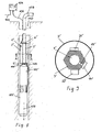
In den Zeichnungen zeigen Fig. 1 einen Gehäuseabschnitt mit guter Wärmeleitfähigkeit eines erfindungsgemäßen Pumpensteuergeräts in Untersicht, Fig. 2 den Gehäuseabschnitt im Schnitt entlang der Linie A-A von Fig. 1, Fig. 3 den Gehäuseabschnitt im Schnitt entlang der Linie B-B von Fig. 3, Fig. 4 eine perspektivische Ansicht des Gehäuseabschnitts von schräg oben, Fig. 5 eine perspektivische Ansicht des Gehäuseabschnitts von schräg unten, die Figuren 6 und 7 perspektivische Ansichten einer ersten Ausführungsform einer erfindungsgemäßen Flüssigkeitspumpenanordnung mit einem auf eine Pumpe aufgesetzten erfindungsgemäßen Pumpensteuergerät, Fig. 8 eine zweite Ausführungsform einer erfindungsgemäßen Flüssigkeitspumpenanordnung mit einer als Tauchmotorpumpe ausgeführten Flüssigkeitspumpe, und Fig. 9 einen Querschnitt durch das bei der Flüssigkeitspumpenanordnung von Fig. 8 verwendete Pumpensteuergerät.1 shows a housing section with good thermal conductivity of a pump control device according to the invention in a bottom view, FIG. 2 shows the housing section in section along the line AA of FIG. 1, FIG. 3 shows the housing section in section along the line BB of FIG. 5 is a perspective view of the housing portion obliquely from below, Figures 6 and 7 are perspective views of a first embodiment of a liquid pump assembly according to the invention with a mounted on a pump pump control device according to the invention, Fig. 8 a FIG. 9 shows a cross-section through the pump control unit used in the fluid pump arrangement of FIG. 8. FIG.
Zunächst auf die Figuren 6 und 7 Bezug nehmend ist darin eine Flüssigkeitspumpenanordnung mit einer Flüssigkeitspumpe 100 dargestellt, die von einem Elektromotor 103 angetrieben wird. Die Flüssigkeitspumpe 100 weist einen Einlassstutzen 101, in den ein Flüssigkeitsstrom gesaugt wird (Pfeil IN), und einen Auslassstutzen 102 auf, aus dem der von der Pumpe geförderte Flüssigkeitsstrom abgegeben wird. Auf dem Auslassstutzen 102 ist ein erfindungsgemäßes Pumpensteuergerät 1 montiert, das ein Gehäuse, bestehend aus einem Deckel 2 und einem als Gehäuseboden ausgebildeten Gehäuseabschnitt 3, aufweist, in dem ein Drehzahlregler aufgenommen ist. Im Gehäusedeckel 2 ist eine Anzeige eines Manometers 14 integriert. Je nach Typ des Elektromotors 103 kann der Drehzahlregler unterschiedlich ausgebildet sein. Ist der Elektromotor 103 beispielsweise ein Drehstrommotor, so kommt als Drehzahlregler ein elektronischer Frequenzumformer zum Einsatz, bei Gleichstrommotoren wird ein Thyristorstromrichter oder ein Spannungsregelgerät eingesetzt. Das Pumpensteuergerät 1 weist einen Anschluss 7 auf, der mit dem Auslassstutzen 102 der Pumpe 100 flüssigkeitsdicht verbunden ist, so dass der gesamte von der Pumpe 100 geförderte Flüssigkeitsstrom in den Anschluss 7 fließt und, nachdem er einen nicht dargestellten Hohlraum im Gehäuseabschnitt 3 durchströmt hat, aus einem im Gehäuseabschnitt 3 ausgebildeten Anschluss 5 wieder austritt (Pfeil OUT). In Fig. 7 ist am Gehäuseabschnitt 3 ein Kabelauslass 16 zu sehen, durch den Steuerungs- und Stromversorgungskabel vom Pumpensteuergerät 1 zum Motor 103 geführt werden können.Referring first to Figures 6 and 7, therein is shown a liquid pump assembly having a
Für die nachfolgenden Erläuterungen wird auch auf die Figuren 1 bis 5 Bezug genommen, die den Gehäuseabschnitt 3 in verschiedenen Ansichten darstellen. Der Gehäuseabschnitt 3 ist als Gussteil aus einer Metalllegierung, wie z.B. Messing, gefertigt und weist daher hervorragende Wärmeleitungseigenschaften auf. Er bildet einen Gehäuseboden, in dem ein Drehzahlregelgerät 20 (siehe Figuren 2 und 3) aufgenommen ist. An der Unterseite des Gehäuseabschnitts 3 ist ein Hohlraum 4 ausgebildet ist, der Anschlüsse 5, 6, 7 aufweist. Die Anschlüsse 5, 6, 7 können mit Flanschen oder als Muffen ausgebildet sein. Jeder dieser Anschlüsse 5, 6, 7 kann mit dem Ausgang einer durch das Pumpensteuergerät zu regelnden Flüssigkeitspumpe verbunden werden und somit als Eingangsanschluss fungieren, oder als Ausgangsanschluss dienen, indem er mit Rohrleitungen verbunden wird, die den Flüssigkeitsstrom zu einem Verbraucher transportieren. Wie anhand der Figuren 6 und 7 gezeigt, ist bei diesem Ausführungsbeispiel der Anschluss 7 als Muffe ausgeführt über den Ausgangsstutzen 102 der Pumpe 100 geschoben und nimmt daher den gesamten von der Pumpe 100 geförderten Flüssigkeitsstrom auf. Der Flüssigkeitsstrom fließt durch den Hohlraum 4 hindurch und wird am Anschluss 5 des Hohlraums 4 wieder abgegeben. Der Gehäuseabschnitt 3 bildet somit eine äußerst effiziente, flüssigkeitsgekühlte Wärmesenke für den Drehzahlregler 20, dessen elektronische Leistungsbauteile wärmeleitend mit dem Gehäuseabschnitt 3 verbunden sind. Wie anhand von Fig. 2 dargestellt, liegen einige der wärmeerzeugenden Bauteile 21, 22 des Drehzahlreglers 20 direkt an einer Wand des Gehäuseabschnitts 3 an und werden durch den direkten Kontakt gekühlt, wobei durch planes Ausbilden der Anlagefläche für die Bauteile 21, 22 am Gehäuseabschnitt 3 für guten Wärmeübergang gesorgt ist. Wie in Fig. 3 dargestellt, sind andere Bauteile 23, 24 des Drehzahlreglers 20 über Wärmeleitmittel 30 mit dem Gehäuseabschnitt 3 verbunden. Dazu sind im Gehäuseabschnitt 3 zwei becherförmige Vertiefungen 8, 9 ausgebildet, die sich benachbart zum Hohlraum 4 erstrecken, wobei die Begrenzungswände des Hohlraums 4 auch Abschnitte der Wände der becherförmigen Vertiefungen 8, 9 bilden. Es sei erwähnt, dass die Vertiefungen 8, 9 flüssigkeitsdicht gegenüber dem Hohlraum 4 abgetrennt sind. Die Bauteile 23, 24, z.B. großvolumige Bauteile wie Elektrolytkondensatoren oder Spulen, sind in die Vertiefungen 8, 9 eingesetzt und mit Wärmeleitmittel 30 umgossen, so dass beste Wärmeleitfähigkeit zwischen diesen Bauteilen und den Wänden der Vertiefungen 8, 9 besteht, wodurch die den Hohlraum 4 durchströmende Flüssigkeit optimal zur Kühlung der Bauteile 23, 24 genutzt wird.For the following explanations, reference is also made to Figures 1 to 5, which illustrate the
Wie erwähnt, wird der Hohlraum 4 des Gehäuseabschnitts 3 des Pumpensteuergeräts 1 vom gesamten geförderten Flüssigkeitsstrom der Pumpe 100 durchströmt, wobei im Hohlraum 4 im Wesentlichen der von der Pumpe erzeugte Förderdruck herrscht. Dieser Druck kann als Ist-Wert zur Regelung der Pumpe herangezogen werden. Deshalb ist im Gehäuseabschnitt 3 eine Durchtrittsöffnung 15 in der das Gehäuseinnere vom Hohlraum 4 abtrennenden Wand ausgebildet. Diese Durchtrittsöffnung 15 weist ein Gewinde auf, so dass ein Sensor, wie z.B. ein Manometer, flüssigkeitsdicht eingeschraubt werden kann, dessen Signale vom Drehzahlregler ausgewertet werden.As mentioned, the
Weiters sind im Gehäuseabschnitt 3 Durchtrittsöffnungen 10, 11, 12, 13 ausgebildet, durch die nicht dargestellte Kabel für die Kommunikation zwischen Drehzahlregler und Pumpenmotor sowie für die Stromversorgung des Drehzahlreglers hindurchführbar sind. Um Feuchtigkeitseintritt in das Gehäuseinnere zu verhindern, können an den Durchtrittsöffnungen 10, 11, 12, 13 Tüllen, Buchsen etc. angeordnet werden.Furthermore, 3 through
Fig. 8 zeigt eine zweite Ausführungsform einer erfindungsgemäßen Flüssigkeitspumpenanordnung in Seitenansicht, teilweise geschnitten. Die Flüssigkeitspumpenanordnung ist in einem Bohrbrunnen 110 untergebracht. Sie umfasst eine als Tauchmotorpumpe ausgebildete Flüssigkeitspumpe 100' und einen die Flüssigkeitspumpe 100' antreibenden elektrischen Antriebsmotor 103', sowie ein erfindungsgemäßes Pumpensteuergerät 1', das an den Ausgang 102' der Flüssigkeitspumpe 100' angeschlossen ist.Fig. 8 shows a second embodiment of a liquid pump assembly according to the invention in side view, partially in section. The fluid pump assembly is housed in a
Fig. 9 zeigt einen schematischen Querschnitt des Pumpensteuergerätes 1' entlang der Linie A-A in Fig. 8. Das Pumpensteuergerät 1' weist ein aus einer zylindrischen Außenwand 2' und einer hohlzylindrischen Innenwand 3' bestehendes Gehäuse auf, indem ein nicht näher dargestellter Drehzahlregler, insbesondere Frequenzumformer, zur Regelung der Drehzahl des elektrischen Antriebsmotors 103' angeordnet ist. Die hohlzylindrische Innenwand 3' besteht aus einem Material mit guter Wärmeleitfähigkeit und definiert in ihrem Inneren einen zylindrischen Hohlraum 4', der - wie aus Fig. 8 ersichtlich - Anschlüsse 5', 6' zum Verbinden mit dem Ausgang 102' der Pumpe 100' bzw. mit einer Rohrleitung 109 aufweist. Durch dieses Ausgestaltung wird der Hohlraum 4' mit dem gesamten von der Flüssigkeitspumpe 100' geförderten Flüssigkeitsstrom durchströmt und daher bestens gekühlt. Der Außenmantel der hohlzylindrischen Innenwand 3' besitzt bei diesem Ausführungsbeispiel eine sechseckige Konfiguration, wodurch er sechs ebene Außenflächen besitzt, auf denen für optimale Kühlung elektronische Leistungsbauteile 21', 22' des Drehzahlreglers, wie z.B. Thyristoren oder Kondensatoren, flächig montiert werden können, z.B. durch Aufschrauben unter vorheriger Einbringung einer Wärmeleitpaste. Die hohlzylindrische Innenwand 3' kann beispielsweise ein einstückiges Strangpressprofilrohr aus Metall sein. Nach der Montage des Drehzahlreglers, insbesondere der elektronischen Leistungsbauteile 21', 22' auf der hohlzylindrischen Innenwand 3', wird über diese Anordnung die zylindrische Außenwand 2' gestülpt und dichtend mit der Innenwand 3' verbunden. Die Außenwand 2' besteht zweckmäßig ebenfalls aus gut wärmeleitendem Material.9 shows a schematic cross-section of the pump control device 1 'along the line AA in FIG. 8. The pump control device 1' has a housing consisting of a cylindrical outer wall 2 'and a hollow cylindrical inner wall 3' by a not closer illustrated speed controller, in particular frequency converter, for controlling the rotational speed of the electric drive motor 103 'is arranged. The hollow cylindrical inner wall 3 'consists of a material with good thermal conductivity and defines in its interior a cylindrical cavity 4', which - as shown in FIG. 8 - connections 5 ', 6' for connecting to the output 102 'of the pump 100' or with a
Nun wieder auf Fig. 8 Bezug nehmend weist das Pumpensteuergerät 1' ein entferntes Bedienteil 104 auf, das an einer für eine Bedienperson leicht zugänglichen Stelle montiert ist. Das Bedienteil 104 kommuniziert über eine Steuerleitung 106 mit dem Pumpensteuergerät 1'. Weiters führt ein Stromversorgungskabel 105 zum Bedienteil 104 und versorgt einerseits das Bedienteil 104 mit elektrischem Strom und andererseits auch das Pumpensteuergerät 1', indem die elektrische Energie des Stromversorgungskabels 105 in die Steuerleitung 106 eingespeist wird. Die in die Steuerleitung 106 eingespeiste elektrische Energie hat einen sinusförmigen Verlauf (z.B. Drehstromsignale) und besitzt die niedrige Netzstromfrequenz von 50 - 60 Hz. Somit werden keine nennenswerten elektromagnetischen Störsignale produziert, auch wenn die Steuerleitung 106 sehr lang ist. Die Steuersignale zwischen Bedienteil 104 und Pumpensteuergerät 1' werden auf eine Trägerfrequenz aufmoduliert und den elektrischen Versorgungssignalen in der Steuerleitung 106 überlagert; im Pumpensteuergerät 1' erfolgt die Abtrennung und Demodulation der Steuersignale. Über das Bedienteil 104 können beispielsweise Soll-Werte übertragen werden, die von einer Regelungsschaltung im Pumpensteuergerät 1' berücksichtigt werden und aufgrund der Regelung elektrische Signale erzeugt werden, die zur Ansteuerung des Antriebsmotors 103' über ein Kabel 107 übertragen werden. Für die Regelung ist es weiters vorteilhaft, wenn ein Drucksensor 14' direkt am Pumpensteuergerät 1' angebracht ist (siehe Fig. 9). Dabei weist die Innenwand 3' eine Durchtrittsöffnung 15' in den Hohlraum 4' zum Anschluss des Drucksensors 14' auf. Bei der Regelung muss zum vom Drucksensor 14' gemessenen Druck nur die zusätzliche, sich aus der Tiefenposition der Flüssigkeitspumpe 100' im Bohrbrunnen 110 ergebende Förderhöhe addiert werden.Referring again to Fig. 8, the pump controller 1 'has a
Wie bereits erwähnt, ist in der vorliegenden Ausführungsform der Flüssigkeitspumpenanordnung die Flüssigkeitspumpe 100' als Tauchmotorpumpe ausgebildet und weist - ebenso wie der Antriebsmotor 103' - eine im Wesentlichen um eine Längsachse 108 rotationssymmetrische Gehäuseform auf. Das Pumpensteuergerät 1' ist dabei koaxial mit der Tauchmotorpumpe 100' verbunden, wodurch sich eine sehr schlanke und kompakte Konfiguration ergibt.As already mentioned, in the present embodiment of the liquid pump arrangement, the liquid pump 100 'is designed as a submersible pump and, like the drive motor 103', has a housing shape that is essentially rotationally symmetrical about a
Claims (16)
Priority Applications (3)
| Application Number | Priority Date | Filing Date | Title |
|---|---|---|---|
| EP04450177A EP1637741A1 (en) | 2004-09-17 | 2004-09-17 | Liquid cooled pump and pump controller |
| CA002511423A CA2511423A1 (en) | 2004-09-17 | 2005-07-05 | Liquid-cooled pump control device and fluid pump assembly |
| US11/181,203 US20060078444A1 (en) | 2004-09-17 | 2005-07-13 | Liquid-cooled pump control device and fluid pump assembly |
Applications Claiming Priority (1)
| Application Number | Priority Date | Filing Date | Title |
|---|---|---|---|
| EP04450177A EP1637741A1 (en) | 2004-09-17 | 2004-09-17 | Liquid cooled pump and pump controller |
Publications (1)
| Publication Number | Publication Date |
|---|---|
| EP1637741A1 true EP1637741A1 (en) | 2006-03-22 |
Family
ID=34933155
Family Applications (1)
| Application Number | Title | Priority Date | Filing Date |
|---|---|---|---|
| EP04450177A Withdrawn EP1637741A1 (en) | 2004-09-17 | 2004-09-17 | Liquid cooled pump and pump controller |
Country Status (3)
| Country | Link |
|---|---|
| US (1) | US20060078444A1 (en) |
| EP (1) | EP1637741A1 (en) |
| CA (1) | CA2511423A1 (en) |
Cited By (3)
| Publication number | Priority date | Publication date | Assignee | Title |
|---|---|---|---|---|
| WO2010064055A1 (en) * | 2008-12-01 | 2010-06-10 | Electronica Products Limited | Cooling electronic circuits |
| WO2013130497A1 (en) * | 2012-02-27 | 2013-09-06 | Magna Powertrain Of America, Inc. | Electric motor -driven pump |
| ITPD20120409A1 (en) * | 2012-12-27 | 2014-06-28 | Dab Pumps Spa | LIQUID FLOW RATE CONTROL EQUIPMENT OF A ELECTRIC PUMP AND THE ELECTRONIC CONTROL TEMPERATURE AND COMMAND OF A PUMPING DEVICE PROVIDING THE ELECTRIC PUMP |
Families Citing this family (31)
| Publication number | Priority date | Publication date | Assignee | Title |
|---|---|---|---|---|
| US8540493B2 (en) | 2003-12-08 | 2013-09-24 | Sta-Rite Industries, Llc | Pump control system and method |
| US8469675B2 (en) | 2004-08-26 | 2013-06-25 | Pentair Water Pool And Spa, Inc. | Priming protection |
| US8602745B2 (en) | 2004-08-26 | 2013-12-10 | Pentair Water Pool And Spa, Inc. | Anti-entrapment and anti-dead head function |
| US7686589B2 (en) | 2004-08-26 | 2010-03-30 | Pentair Water Pool And Spa, Inc. | Pumping system with power optimization |
| US8480373B2 (en) | 2004-08-26 | 2013-07-09 | Pentair Water Pool And Spa, Inc. | Filter loading |
| US8019479B2 (en) | 2004-08-26 | 2011-09-13 | Pentair Water Pool And Spa, Inc. | Control algorithm of variable speed pumping system |
| US7854597B2 (en) | 2004-08-26 | 2010-12-21 | Pentair Water Pool And Spa, Inc. | Pumping system with two way communication |
| US7845913B2 (en) | 2004-08-26 | 2010-12-07 | Pentair Water Pool And Spa, Inc. | Flow control |
| US7874808B2 (en) | 2004-08-26 | 2011-01-25 | Pentair Water Pool And Spa, Inc. | Variable speed pumping system and method |
| US20080286134A1 (en) * | 2007-05-16 | 2008-11-20 | Steven Regalado | Submersible pumping systems and methods for deep well applications |
| US8579600B2 (en) | 2008-03-28 | 2013-11-12 | Sta-Rite Industries, Llc | System and method for portable battery back-up sump pump |
| US8313306B2 (en) | 2008-10-06 | 2012-11-20 | Pentair Water Pool And Spa, Inc. | Method of operating a safety vacuum release system |
| US8564233B2 (en) | 2009-06-09 | 2013-10-22 | Sta-Rite Industries, Llc | Safety system and method for pump and motor |
| US9556874B2 (en) | 2009-06-09 | 2017-01-31 | Pentair Flow Technologies, Llc | Method of controlling a pump and motor |
| US8760089B2 (en) * | 2009-11-30 | 2014-06-24 | Franklin Electric Company, Inc. | Variable speed drive system |
| BR112013001311A2 (en) | 2010-07-21 | 2016-05-17 | Itt Mfg Entpr Llc | pump designed for installation conversion |
| BR112013014476A2 (en) | 2010-12-08 | 2016-09-20 | Pentair Water Pool & Spa Inc | vacuum relief relief valve for a vacuum release safety system |
| US8664903B2 (en) | 2011-06-27 | 2014-03-04 | Franklin Electric Company, Inc. | Adaptive flux control drive |
| CA2808939C (en) * | 2012-05-04 | 2019-12-03 | Sulzer Pump Solutions Ab | Pump system |
| US9885360B2 (en) | 2012-10-25 | 2018-02-06 | Pentair Flow Technologies, Llc | Battery backup sump pump systems and methods |
| US9383244B2 (en) | 2012-10-25 | 2016-07-05 | Pentair Flow Technologies, Llc | Fluid level sensor systems and methods |
| US9638193B2 (en) | 2012-10-25 | 2017-05-02 | Pentair Flow Technologies, Llc | Sump pump remote monitoring systems and methods |
| US10808697B2 (en) * | 2016-07-20 | 2020-10-20 | Stackpole International Engineered Products, Ltd. | Pump assembly having integrated controller and motor with internal active cooling |
| JP6852457B2 (en) * | 2017-02-27 | 2021-03-31 | 株式会社島津製作所 | Power supply integrated vacuum pump |
| US10907901B2 (en) | 2018-12-03 | 2021-02-02 | Balboa Water Group, Llc | Cooling device and system for bathing installation pump electrical drive |
| CN109819637A (en) * | 2019-04-09 | 2019-05-28 | 苏州玲珑汽车科技有限公司 | A kind of automobile controller cooling system |
| RU2717484C1 (en) * | 2019-07-24 | 2020-03-23 | Валерий Эдуардович Габдрахимов | Device for cooling electric installations for pump units installed in transfer stations |
| USD1013732S1 (en) * | 2022-02-11 | 2024-02-06 | Graco Minnesota Inc. | Displacement pump |
| USD1014561S1 (en) * | 2022-02-11 | 2024-02-13 | Graco Minnesota Inc. | Displacement pump control box with center section |
| USD1006830S1 (en) * | 2022-02-11 | 2023-12-05 | Graco Minnesota Inc. | Control box for a displacement pump |
| USD1014562S1 (en) * | 2022-02-11 | 2024-02-13 | Graco Minnesota Inc. | Displacement pump |
Citations (3)
| Publication number | Priority date | Publication date | Assignee | Title |
|---|---|---|---|---|
| US5454697A (en) * | 1993-03-24 | 1995-10-03 | Aisan Kogyo Kabushiki Kaisha | Electrically operated pump assembly with an externally installed control circuit |
| US5613844A (en) * | 1994-11-15 | 1997-03-25 | Walbro Corporation | Submersible electronic drive module |
| US6132184A (en) * | 1998-11-05 | 2000-10-17 | Ford Motor Company | Reservoir apparatus for an electronically controlled electric pump |
Family Cites Families (12)
| Publication number | Priority date | Publication date | Assignee | Title |
|---|---|---|---|---|
| CA1227886A (en) * | 1984-01-26 | 1987-10-06 | Haruhiko Yamamoto | Liquid-cooling module system for electronic circuit components |
| US4945884A (en) * | 1989-10-24 | 1990-08-07 | General Motors Corporation | Modular fuel delivery system |
| US5080077A (en) * | 1990-06-01 | 1992-01-14 | General Motors Corporation | Modular fuel delivery system |
| US5224356A (en) * | 1991-09-30 | 1993-07-06 | Triangle Research & Development Corp. | Method of using thermal energy absorbing and conducting potting materials |
| JP2745948B2 (en) * | 1992-04-06 | 1998-04-28 | 日本電気株式会社 | Integrated circuit cooling structure |
| US5459640A (en) * | 1994-09-23 | 1995-10-17 | Motorola, Inc. | Electrical module mounting apparatus and method thereof |
| US5538396A (en) * | 1994-10-24 | 1996-07-23 | Meierhoefer; Ned S. | Water pumping system |
| US5804297A (en) * | 1995-07-05 | 1998-09-08 | Colvin; David P. | Thermal insulating coating employing microencapsulated phase change material and method |
| US6251970B1 (en) * | 1996-10-25 | 2001-06-26 | Northrop Grumman Corporation | Heat absorbing surface coating |
| ATE350578T1 (en) * | 2001-09-28 | 2007-01-15 | Environ Prod Inc | FUEL DELIVERY PUMP |
| US6783336B2 (en) * | 2002-06-28 | 2004-08-31 | Visteon Global Technologies, Inc. | Fuel sender assembly |
| US6729848B1 (en) * | 2002-12-12 | 2004-05-04 | Hasslen, Iii John S. | Sensor mount for sump draining apparatus |
-
2004
- 2004-09-17 EP EP04450177A patent/EP1637741A1/en not_active Withdrawn
-
2005
- 2005-07-05 CA CA002511423A patent/CA2511423A1/en not_active Abandoned
- 2005-07-13 US US11/181,203 patent/US20060078444A1/en not_active Abandoned
Patent Citations (3)
| Publication number | Priority date | Publication date | Assignee | Title |
|---|---|---|---|---|
| US5454697A (en) * | 1993-03-24 | 1995-10-03 | Aisan Kogyo Kabushiki Kaisha | Electrically operated pump assembly with an externally installed control circuit |
| US5613844A (en) * | 1994-11-15 | 1997-03-25 | Walbro Corporation | Submersible electronic drive module |
| US6132184A (en) * | 1998-11-05 | 2000-10-17 | Ford Motor Company | Reservoir apparatus for an electronically controlled electric pump |
Non-Patent Citations (1)
| Title |
|---|
| HARRIS N C ET AL: "Design of an integrated motor/controller drive for an automotive water pump application", CONFERENCE RECORD OF THE 2002 IEEE INDUSTRY APPLICATIONS CONFERENCE. 37TH IAS ANNUAL MEETING . PITTSBURGH, PA, OCT. 13 - 18, 2002, CONFERENCE RECORD OF THE IEEE INDUSTRY APPLICATIONS CONFERENCE. IAS ANNUAL MEETING, NEW YORK, NY : IEEE, US, vol. 1 OF 4. CONF. 37, 13 October 2002 (2002-10-13), pages 2028 - 2035, XP010610156, ISBN: 0-7803-7420-7 * |
Cited By (4)
| Publication number | Priority date | Publication date | Assignee | Title |
|---|---|---|---|---|
| WO2010064055A1 (en) * | 2008-12-01 | 2010-06-10 | Electronica Products Limited | Cooling electronic circuits |
| WO2013130497A1 (en) * | 2012-02-27 | 2013-09-06 | Magna Powertrain Of America, Inc. | Electric motor -driven pump |
| ITPD20120409A1 (en) * | 2012-12-27 | 2014-06-28 | Dab Pumps Spa | LIQUID FLOW RATE CONTROL EQUIPMENT OF A ELECTRIC PUMP AND THE ELECTRONIC CONTROL TEMPERATURE AND COMMAND OF A PUMPING DEVICE PROVIDING THE ELECTRIC PUMP |
| EP2749770A1 (en) * | 2012-12-27 | 2014-07-02 | Dab Pumps S.p.A. | Apparatus for controlling the flow-rate of liquid of an electric pump and the temperature of the control and actuation electronics of a pumping device that carries the electric pump |
Also Published As
| Publication number | Publication date |
|---|---|
| CA2511423A1 (en) | 2006-03-17 |
| US20060078444A1 (en) | 2006-04-13 |
Similar Documents
| Publication | Publication Date | Title |
|---|---|---|
| EP1637741A1 (en) | Liquid cooled pump and pump controller | |
| DE19704226B4 (en) | Klemmdeckelumrichter | |
| DE3642724C2 (en) | ||
| EP2122166B1 (en) | Motor pump unit particularly for a high-pressure cleaning device | |
| EP2003322B1 (en) | Fuel pump with electronically commuted motor | |
| DE19511114C1 (en) | Electric motor | |
| DE3820003C2 (en) | ||
| EP1574714B1 (en) | Pump unit | |
| EP2607707B2 (en) | Electric motor | |
| EP2072828A1 (en) | Wet-running centrifugal pump | |
| DE102006047269A1 (en) | converter motor | |
| DE3642723A1 (en) | STATIC FREQUENCY INVERTER, ESPECIALLY FREQUENCY INVERTER FOR CONTROLLING AND / OR REGULATING THE PERFORMANCE SIZE OF AN ELECTRIC MOTOR | |
| DE102013012143A1 (en) | Coolant pump for a motor vehicle for cooling an internal combustion engine or an alternative drive device | |
| EP2905471B1 (en) | Electrically operated motor vehicle coolant pump | |
| WO2018041401A1 (en) | Motor pump device | |
| DE19727202A1 (en) | Submersible motor unit | |
| DE3642726A1 (en) | Variable-speed pump set | |
| DE102016122702B4 (en) | Electric coolant pump with ECU cooling | |
| EP3881414A1 (en) | Electric motor | |
| EP2607708B1 (en) | Electric motor | |
| DE102011083925B4 (en) | fan device | |
| EP1343645B1 (en) | Vehicle heating device with an integrated heat transfer circulation pump | |
| EP1104079A2 (en) | Electric motor, in particular for a centrifugal pump | |
| DE102021208945A1 (en) | Electronic device for a heat pump and heat pump device with such an electronic device | |
| DE102020105337B4 (en) | Thermally optimized coolant pump |
Legal Events
| Date | Code | Title | Description |
|---|---|---|---|
| PUAI | Public reference made under article 153(3) epc to a published international application that has entered the european phase |
Free format text: ORIGINAL CODE: 0009012 |
|
| AK | Designated contracting states |
Kind code of ref document: A1 Designated state(s): AT BE BG CH CY CZ DE DK EE ES FI FR GB GR HU IE IT LI LU MC NL PL PT RO SE SI SK TR |
|
| AX | Request for extension of the european patent |
Extension state: AL HR LT LV MK |
|
| 17P | Request for examination filed |
Effective date: 20060911 |
|
| AKX | Designation fees paid |
Designated state(s): AT BE BG CH CY CZ DE DK EE ES FI FR GB GR HU IE IT LI LU MC NL PL PT RO SE SI SK TR |
|
| 17Q | First examination report despatched |
Effective date: 20070322 |
|
| GRAP | Despatch of communication of intention to grant a patent |
Free format text: ORIGINAL CODE: EPIDOSNIGR1 |
|
| STAA | Information on the status of an ep patent application or granted ep patent |
Free format text: STATUS: THE APPLICATION IS DEEMED TO BE WITHDRAWN |
|
| 18D | Application deemed to be withdrawn |
Effective date: 20091222 |