EP1637967A2 - Portable computer docking station - Google Patents
Portable computer docking station Download PDFInfo
- Publication number
- EP1637967A2 EP1637967A2 EP05017904A EP05017904A EP1637967A2 EP 1637967 A2 EP1637967 A2 EP 1637967A2 EP 05017904 A EP05017904 A EP 05017904A EP 05017904 A EP05017904 A EP 05017904A EP 1637967 A2 EP1637967 A2 EP 1637967A2
- Authority
- EP
- European Patent Office
- Prior art keywords
- docking
- portable computer
- cradle
- docking station
- base
- Prior art date
- Legal status (The legal status is an assumption and is not a legal conclusion. Google has not performed a legal analysis and makes no representation as to the accuracy of the status listed.)
- Ceased
Links
Images


Classifications
-
- G—PHYSICS
- G06—COMPUTING; CALCULATING OR COUNTING
- G06F—ELECTRIC DIGITAL DATA PROCESSING
- G06F1/00—Details not covered by groups G06F3/00 - G06F13/00 and G06F21/00
- G06F1/16—Constructional details or arrangements
- G06F1/1613—Constructional details or arrangements for portable computers
- G06F1/1632—External expansion units, e.g. docking stations
-
- Y—GENERAL TAGGING OF NEW TECHNOLOGICAL DEVELOPMENTS; GENERAL TAGGING OF CROSS-SECTIONAL TECHNOLOGIES SPANNING OVER SEVERAL SECTIONS OF THE IPC; TECHNICAL SUBJECTS COVERED BY FORMER USPC CROSS-REFERENCE ART COLLECTIONS [XRACs] AND DIGESTS
- Y10—TECHNICAL SUBJECTS COVERED BY FORMER USPC
- Y10S—TECHNICAL SUBJECTS COVERED BY FORMER USPC CROSS-REFERENCE ART COLLECTIONS [XRACs] AND DIGESTS
- Y10S248/00—Supports
- Y10S248/917—Video display screen support
Definitions
- Portable computers are being increasingly used for both mobile and workstation or desktop applications or environments.
- portable computers are generally used independently as a mobile device and as an office or desktop workstation via a docking station, thereby enabling the portable computer to be used as a desktop or workstation system while providing mobile convenience as well.
- conserving desktop work space and providing an ergonomic environment for using the portable computer in a desktop application is an important design objective.
- a portable computer docking station comprises a cradle coupled to a docking base where the cradle is adapted to receive a portable computer.
- the docking station also comprises a wireless receiver adapted to communicate a wireless input signal received by the docking station to the portable computer.
- a portable computer docking station comprises a cradle pivotally coupled to a docking base where the docking base is adapted to be communicatively coupled to a portable computer disposed in the cradle.
- the cradle is also adapted to support the portable computer in a display-open position.
- a portable computer docking station comprises a cradle pivotally coupled to a docking base where the cradle is adapted to receive a portable computer.
- the docking station also comprises at least one connector element adapted to releasably engage the portable computer to communicatively couple the portable computer to the docking base.
- the docking station further comprises at least one actuation element adapted to releasably secure the cradle in at least one of a plurality of pivot positions relative to the docking base.
- a portable computer docking station comprises a cradle coupled to a docking base where the cradle is adapted to receive a portable computer.
- the portable computer docking station also comprises an interchangeable drive assembly removably couplable to the docking base.
- FIGURES 1A and 1B are diagrams illustrating an embodiment of a portable computer docking station with and without, respectively, a portable computer disposed therein in accordance with the present invention
- FIGURES 2A and 2B are diagrams illustrating docking of a portable computer to an embodiment of a portable computer docking station in accordance with the present invention
- FIGURES 3 and 4 are diagrams illustrating an embodiment of an actuation system for the portable computer docking station of the present invention
- FIGURE 5 is a diagram illustrating the embodiment of the portable computer docking station illustrated in FIGURES 1-4 in a reclined position;
- FIGURE 6 is a diagram illustrating an exploded view of an embodiment of a drive assembly for the portable computer docking station illustrated in FIGURES 1-5 in accordance with the present invention.
- FIGURE 7 is a diagram illustrating the drive assembly illustrated in FIGURE 6 inserted into the portable docking station in accordance with the present invention.
- FIGURES 1-7 of the drawings like numerals being used for like and corresponding parts of the various drawings.
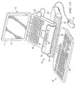
- FIGURES 1A and 1B are diagrams illustrating an embodiment of a portable computer docking station 10 in accordance with the present invention with and without, respectively, a portable computer 12 docked thereto.
- portable computer 12 comprises a notebook or laptop computer 14 having a base member 16 disposed within a cradle 18 of docking station 10 and a display member 20.
- portable computer 12 is illustrated as being docked in docking station 10 having display member 20 in an open position relative to base member 16 such that only base member 16 is disposed within cradle 18, thereby enabling portable computer 12 to be docked in docking station 10 in a display-open position.
- portable computer 12 may also be docked in docking station 10 with display member 20 closed relative to base member 16.
- docking station 10 comprises cradle 18 pivotally coupled to a docking base 30.
- docking base 30 comprises a plurality of audio speakers for providing audio output to a user of docking station 10 based on audio data received or otherwise provided by portable computer 12 and/or another external resource coupled to docking station 10.
- docking base 30 comprises a left channel audio speaker 34, a right channel audio speaker 36, and a center channel audio speaker 38.
- speakers 34, 36 and 38 may be otherwise located on docking station 10.
- docking base 30 is configured with a variety of types of devices to facilitate interfacing or otherwise communicating with portable computer 12 and/or other external resources via docking station 10 such as, but not limited to, a hard drive and input/output ports.
- one or more peripheral devices 40 such as, but not limited to, a keyboard 42 and mouse 44, are communicatively coupled to docking station 10 to enable interfacing or otherwise communicating with docking station 10 and/or portable computer 12.
- Docking station 10 may be configured for wired or wireless communications with external resources such as, but not limited to, a network or peripheral devices 40.
- mouse 44 is coupled to docking base 30 via a wired connection
- keyboard 42 is configured for wireless communications with docking station 10.
- docking station 10 comprises a wireless receiver 50 disposed on cradle 18 for facilitating wireless communications between docking station 10 and a user of docking station 10 (e.g., via wireless peripheral devices 40 and/or other devices or control mechanisms).
- wireless receiver 50 is located on cradle 18 to provide greater visibility and/or access to wireless receiver 50 from peripheral devices 40 or other types of devices or control mechanisms.
- wireless receiver 50 may be otherwise located on docking station 10.
- control element 52 is disposed on cradle 18 to facilitate control and/or interaction with one or more corresponding features or functions of docking station 10 and/or portable computer 12.
- control element 52 comprises a slidebar element 54 to facilitate volume or balance control for audio signals emitted by speakers 34, 36 and and/or 38.
- control element 52 may be otherwise associated with another feature or function of docking station 10 and/or portable computer 12.
- a single control element 52 is illustrated; however, it should be understood that a greater quantity of control elements 52 may be provided on docking station 10.
- control elements 52 are located on cradle 18 to facilitate user accessibility to control elements 52.
- control elements 52 may be otherwise located on docking station 10.
- portable computer 12 is communicatively coupled to docking base 30 via a wired electrical connector element 60.
- docking station 10 may also be configured for wireless communications between portable computer 12 and docking station 10.
- docking station 10 comprises a non-skid element 62, such as a rubber pad element or another type of non-skid element, disposed in cradle 18 to stabilize and/or substantially prevent movement of portable computer 12 while disposed within cradle 18.
- a non-skid element 62 such as a rubber pad element or another type of non-skid element
- FIGURES 2A and 2B are diagrams illustrating another view of docking station 10 in accordance with an embodiment of the present invention without and with, respectively, portable computer 12 docked thereto.
- connector element 60 comprises a retractable connector element 60 such that connector element 60 may be extended or retracted relative to cradle 18 to facilitate a variety of different connector locations of portable computer 12 for communicatively coupling portable computer 12 to docking station 10.
- a rearward surface 66 of cradle 18 comprises a recessed area 68 to facilitate storage of connector element 60 in a retracted position.
- connector element 60 may be withdrawn from recessed area 68 and pulled outwardly or otherwise extended relative to cradle 18 in a variety of different directions relative to cradle 18 to facilitate engagement with a corresponding connector of portable computer 12.
- Cradle 18 may be configured with a variety of different types of retraction mechanisms to facilitate retraction or an inwardly biased mechanism for drawing a cable 70 of connector element 60 inwardly into cradle 18 such that, after disengagement of connector element 60 from portable computer 12, or while engaged thereto, excess cable 70 of connector element 60 is automatically retracted into cradle 18 to facilitate convenient storage of connector element 60 within cradle 18 and/or retraction of excess cable 70.
- docking station 10 may be configured to enable excess cable 70 to be manually retracted or stored within cradle 18.
- rearward surface 66 of cradle 18 comprises a plurality of recessed cable channels 74 to facilitate storage of cable 70 therein while connector element 60 is in an extended position relative to cradle 18.
- three cable channels 74 are illustrated; however, it should be understood that a greater or fewer quantity of cable channels 74 may be provided on cradle 18 to facilitate storage of cable 70 in a variety of different directions relative to portable computer 12.
- a rearward surface 78 of docking base 30 comprises a plurality of input/output ports 80 for communicatively coupling docking base 30 to portable computer 12 and/or other resources such as, but not limited to, a power source, a computer network, peripheral devices 40, a telephone jack connection, auxiliary audio systems or components, and/or other types of devices or resources.
- input/output ports 80 may be otherwise located on docking base 30.
- connector element 60 is communicatively coupled to docking base 30 to provide communications or otherwise providing an interface between docking base 30 and portable computer 12.
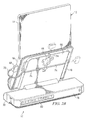
- FIGURE 3 is a diagram illustrating an embodiment of docking station 10 in accordance with the present invention with portions thereof removed for illustrating an actuation system 90 for facilitating pivotal movement of cradle 18 relative to docking base 30.
- actuation system 90 comprises a plurality of actuation elements 92 each coupled to a spring-based latch mechanism 96.
- cradle 18 is pivotally coupled to docking base 30 via a mounting bracket 98 coupled to rearward surface 66 of cradle 18.
- Mounting bracket 98 is rotatably coupled to a support rod 100, which is in turn coupled to docking base 30 via a support member 102.
- Spring-based latch mechanisms 96 are coupled to mounting bracket 98 to enable releasable engagement of mounting bracket 98 relative to support rod 100 in a plurality of different pivotal positions to enable cradle 18 to be releasably secured in any of the plurality of pivot positions of cradle 18 relative to docking base 30.
- FIGURE 3 two actuation elements 92 and latch mechanisms 96 are illustrated; however, it should be understood that a greater or fewer quantity of actuation elements 92 and latch mechanisms 96 may be used.
- pivotal control systems or mechanisms may be used to provide pivotal movement of cradle 18 relative to docking base 30 and facilitate releasably securing cradle 18 in a desired pivot position relative to docking base 30.
- a user of docking station 10 engages at least one of actuation elements 92 and actuates the corresponding actuation element 92 in the directed indicated generally by 104.
- docking station 10 is configured such that actuation of any one of actuation elements 92 causes latch element 96 to disengage relative to support rod 100, thereby enabling pivotal movement of cradle 18 relative to support rod 100.
- actuation of any of actuation elements 92 may be performed via a single hand of the user to facilitate pivotal movement of cradle 18 relative to docking base 30.
- cradle 18 may be pivotally manipulated into any one of a plurality of different pivot positions relative to docking base 30, upon which the user may disengage actuation element 92, thereby causing actuation element 92 to retract in a direction generally opposite that indicated by 104 via spring-based latch mechanism 96, thereby causing latch mechanism 96 to engage and otherwise releasably secure cradle 18 in the desired pivot position relative to docking base 30.
- FIGURES 4 and 5 are diagrams illustrating an embodiment of docking station 10 in accordance with the present invention having cradle 18 in different pivot positions relative to docking base 30.
- cradle 18 is configured as a J-shaped cradle 18 to receive and support portable computer 12.
- wireless receiver 50 disposed on cradle 18 comprises a bubble-type wireless receiver 50 to enable wireless access to receiver 50 from a plurality of different pivot positions of cradle 18 relative to docking base 30.
- wireless receiver 50 extends beyond or above an adjacent mounting surface 108 of cradle 18 such that a wireless input signal may be received by wireless receiver 50 while cradle 18 is disposed in each of a plurality of different pivot positions relative to docking base 30.
- wireless receiver 50 remains visible or otherwise accessible to a wireless input signal received from a direction indicated generally by 110.
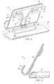
- FIGURES 6 and 7 are diagrams illustrating exploded and assembled views, respectively of a drive assembly 120 relative to docking base 30 in accordance with the present invention.
- docking station 10 is adapted to enable easy interchangeability of drive devices relative to docking base 30 while reducing and/or minimizing the complexity of hardware/software associated with a motherboard of the docking base 30.
- drive assembly 120 comprises a drive enclosure 122 housing a drive device 124.
- Drive device 124 may comprise any type of drive device such as, but not limited to, a hard drive, an optical drive (e.g., compact disc (CD) and/or digital video disc (DVD) drive) and/or a disk drive.
- Drive assembly 120 also comprises a connector element 126 adapted to engage and cooperate with a corresponding connector element disposed on a motherboard disposed within docking base 30 (not illustrated).
- drive assembly 120 also comprises a power port 128 disposed on connector element 126 to enable an independent power supply to be coupled to drive device 124 when inserted into docking base 30.
- power port 128 may be otherwise located on drive assembly 120.
- drive assembly 120 in operation according to the embodiment illustrated in FIGURES 6 and 7, is adapted to be slidably inserted into a drive cavity 130 of docking base 30, thereby engaging connector element 126 with a corresponding connector element coupled to a motherboard disposed within docking base 30 to communicatively couple drive assembly 120 to various hardware/software components of docking base 30.
- docking base 30 also comprises a recessed portion 132 for readily disengaging and removing drive assembly 120 from docking base 30.
- drive enclosure 122 comprises an exterior housing element 134 adapted to cooperate, preferably mechanically and cosmetically, with a housing 136 of docking base 30.
- housing element 134 with recessed portion 132 provides or otherwise enables an edge or portion 138 of housing element 134 to be engaged by a user to disengage and remove drive assembly 120 from docking base 30.
- a power medium 140 is illustrated for providing power to drive assembly 120.
- power medium 140 extends through an opening 142 formed in rearward surface 78 of housing 136 to engage power port 128 (illustrated in FIGURE 6) of drive assembly.
- power is supplied to drive assembly 120 via power medium 140 independently of a motherboard or other connection within docking base 30, thereby reducing the complexity, hardware/software, and cost associated with components within docking base 30.
- system 10 may be otherwise configured such that power for drive assembly 120 is provided via components of docking base 30.
- embodiments of the present invention provide a portable computer docking station 10 enabling a portable computer docked thereto to be positioned in a variety of different angular positions and, if desired, docked in a display-open position. Additionally, embodiments of the present invention provide a portable computer docking station 10 adapted to receive wireless input signals from peripheral devices (e.g., a wireless keyboard or mouse) or another type of wireless transmitter or control mechanism (e.g., a wireless remote control unit) while the cradle 18 of station 10 is disposed in a variety of different pivot positions.
- peripheral devices e.g., a wireless keyboard or mouse
- another type of wireless transmitter or control mechanism e.g., a wireless remote control unit
- embodiments of the present invention enable easy and convenient manipulation of an angular position of a portable computer docked in station 10, thereby providing a user with variety of positions in which to position a display device of the portable computer. Additionally, embodiments of the present invention provide ready interchangeability of a drive device. For example, in some embodiments of the present invention, different types of drive devices 124 are easily interchanged via different drive assemblies 120 to accommodate different media types, different storage requirements, and/or different data sources.
Abstract

Description
- Portable computers are being increasingly used for both mobile and workstation or desktop applications or environments. For example, portable computers are generally used independently as a mobile device and as an office or desktop workstation via a docking station, thereby enabling the portable computer to be used as a desktop or workstation system while providing mobile convenience as well. However, conserving desktop work space and providing an ergonomic environment for using the portable computer in a desktop application is an important design objective.
- In accordance with one embodiment of the present invention, a portable computer docking station comprises a cradle coupled to a docking base where the cradle is adapted to receive a portable computer. The docking station also comprises a wireless receiver adapted to communicate a wireless input signal received by the docking station to the portable computer.
- In accordance with another embodiment of the present invention, a portable computer docking station comprises a cradle pivotally coupled to a docking base where the docking base is adapted to be communicatively coupled to a portable computer disposed in the cradle. The cradle is also adapted to support the portable computer in a display-open position.
- In accordance with yet another embodiment of the present invention, a portable computer docking station comprises a cradle pivotally coupled to a docking base where the cradle is adapted to receive a portable computer. The docking station also comprises at least one connector element adapted to releasably engage the portable computer to communicatively couple the portable computer to the docking base. The docking station further comprises at least one actuation element adapted to releasably secure the cradle in at least one of a plurality of pivot positions relative to the docking base.
- In accordance with yet another embodiment of the present invention, a portable computer docking station comprises a cradle coupled to a docking base where the cradle is adapted to receive a portable computer. The portable computer docking station also comprises an interchangeable drive assembly removably couplable to the docking base.
- For a more complete understanding of the present invention and the advantages thereof, reference is now made to the following descriptions taken in connection with the accompanying drawings in which:
- FIGURES 1A and 1B are diagrams illustrating an embodiment of a portable computer docking station with and without, respectively, a portable computer disposed therein in accordance with the present invention;
- FIGURES 2A and 2B are diagrams illustrating docking of a portable computer to an embodiment of a portable computer docking station in accordance with the present invention;
- FIGURES 3 and 4 are diagrams illustrating an embodiment of an actuation system for the portable computer docking station of the present invention;
- FIGURE 5 is a diagram illustrating the embodiment of the portable computer docking station illustrated in FIGURES 1-4 in a reclined position;
- FIGURE 6 is a diagram illustrating an exploded view of an embodiment of a drive assembly for the portable computer docking station illustrated in FIGURES 1-5 in accordance with the present invention; and
- FIGURE 7 is a diagram illustrating the drive assembly illustrated in FIGURE 6 inserted into the portable docking station in accordance with the present invention.
- The preferred embodiments of the present invention and the advantages thereof are best understood by referring to FIGURES 1-7 of the drawings, like numerals being used for like and corresponding parts of the various drawings.
- FIGURES 1A and 1B are diagrams illustrating an embodiment of a portable
computer docking station 10 in accordance with the present invention with and without, respectively, aportable computer 12 docked thereto. In the embodiment illustrated in FIGURE 1A,portable computer 12 comprises a notebook orlaptop computer 14 having abase member 16 disposed within acradle 18 ofdocking station 10 and adisplay member 20. In the embodiment illustrated in FIGURE 1A,portable computer 12 is illustrated as being docked indocking station 10 havingdisplay member 20 in an open position relative tobase member 16 such that onlybase member 16 is disposed withincradle 18, thereby enablingportable computer 12 to be docked indocking station 10 in a display-open position. However, it should be understood thatportable computer 12 may also be docked indocking station 10 withdisplay member 20 closed relative tobase member 16. - In the embodiment illustrated in FIGURES 1A and 1B,
docking station 10 comprisescradle 18 pivotally coupled to adocking base 30. In the embodiment illustrated in FIGURES 1A and 1B,docking base 30 comprises a plurality of audio speakers for providing audio output to a user ofdocking station 10 based on audio data received or otherwise provided byportable computer 12 and/or another external resource coupled todocking station 10. For example, in the embodiment illustrated in FIGURES 1A and 1B,docking base 30 comprises a leftchannel audio speaker 34, a rightchannel audio speaker 36, and a centerchannel audio speaker 38. However, it should be understood that a greater or fewer quantity of audio speakers may be provided ondocking base 30. Further,speakers docking station 10. - Additionally, in some embodiments of the present invention,
docking base 30 is configured with a variety of types of devices to facilitate interfacing or otherwise communicating withportable computer 12 and/or other external resources viadocking station 10 such as, but not limited to, a hard drive and input/output ports. For example, as illustrated in FIGURE 1A, one or moreperipheral devices 40, such as, but not limited to, akeyboard 42 and mouse 44, are communicatively coupled todocking station 10 to enable interfacing or otherwise communicating withdocking station 10 and/orportable computer 12.Docking station 10 may be configured for wired or wireless communications with external resources such as, but not limited to, a network orperipheral devices 40. For example, as illustrated in FIGURE 1A, mouse 44 is coupled todocking base 30 via a wired connection, andkeyboard 42 is configured for wireless communications withdocking station 10. - In the embodiment illustrated in FIGURES 1A and 1B,
docking station 10 comprises awireless receiver 50 disposed oncradle 18 for facilitating wireless communications betweendocking station 10 and a user of docking station 10 (e.g., via wirelessperipheral devices 40 and/or other devices or control mechanisms). Preferably,wireless receiver 50 is located oncradle 18 to provide greater visibility and/or access towireless receiver 50 fromperipheral devices 40 or other types of devices or control mechanisms. However, it should be understood thatwireless receiver 50 may be otherwise located ondocking station 10. - In the embodiment illustrated in FIGURES 1A and 1B, at least one
control element 52 is disposed oncradle 18 to facilitate control and/or interaction with one or more corresponding features or functions ofdocking station 10 and/orportable computer 12. For example, in the embodiment illustrated in FIGURES 1A and 1B,control element 52 comprises aslidebar element 54 to facilitate volume or balance control for audio signals emitted byspeakers control element 52 may be otherwise associated with another feature or function ofdocking station 10 and/orportable computer 12. In the embodiment illustrated in FIGURES 1A and 1B, asingle control element 52 is illustrated; however, it should be understood that a greater quantity ofcontrol elements 52 may be provided ondocking station 10. Preferably,control elements 52 are located oncradle 18 to facilitate user accessibility tocontrol elements 52. However, it should also be understood thatcontrol elements 52 may be otherwise located ondocking station 10. - In the embodiment illustrated in FIGURE 1A,
portable computer 12 is communicatively coupled todocking base 30 via a wiredelectrical connector element 60. However, it should be understood thatdocking station 10 may also be configured for wireless communications betweenportable computer 12 anddocking station 10. Additionally, as illustrated in FIGURE 1B,docking station 10 comprises anon-skid element 62, such as a rubber pad element or another type of non-skid element, disposed incradle 18 to stabilize and/or substantially prevent movement ofportable computer 12 while disposed withincradle 18. However, it should also be understood that, in other embodiments of the present invention,docking station 10 may be configured withoutnon-skid element 62. - FIGURES 2A and 2B are diagrams illustrating another view of
docking station 10 in accordance with an embodiment of the present invention without and with, respectively,portable computer 12 docked thereto. In the embodiment illustrated in FIGURES 2A and 2B,connector element 60 comprises aretractable connector element 60 such thatconnector element 60 may be extended or retracted relative tocradle 18 to facilitate a variety of different connector locations ofportable computer 12 for communicatively couplingportable computer 12 todocking station 10. For example, in the embodiment illustrated in FIGURES 2A and 2B, arearward surface 66 ofcradle 18 comprises arecessed area 68 to facilitate storage ofconnector element 60 in a retracted position. In operation,connector element 60 may be withdrawn fromrecessed area 68 and pulled outwardly or otherwise extended relative tocradle 18 in a variety of different directions relative tocradle 18 to facilitate engagement with a corresponding connector ofportable computer 12.Cradle 18 may be configured with a variety of different types of retraction mechanisms to facilitate retraction or an inwardly biased mechanism for drawing acable 70 ofconnector element 60 inwardly intocradle 18 such that, after disengagement ofconnector element 60 fromportable computer 12, or while engaged thereto,excess cable 70 ofconnector element 60 is automatically retracted intocradle 18 to facilitate convenient storage ofconnector element 60 withincradle 18 and/or retraction ofexcess cable 70. However, it should also be understood thatdocking station 10 may be configured to enableexcess cable 70 to be manually retracted or stored withincradle 18. - In the embodiment illustrated in FIGURES 2A and 2B,
rearward surface 66 ofcradle 18 comprises a plurality ofrecessed cable channels 74 to facilitate storage ofcable 70 therein whileconnector element 60 is in an extended position relative tocradle 18. In the embodiment illustrated in FIGURES 2A and 2B, threecable channels 74 are illustrated; however, it should be understood that a greater or fewer quantity ofcable channels 74 may be provided oncradle 18 to facilitate storage ofcable 70 in a variety of different directions relative toportable computer 12. - As illustrated in FIGURES 2A and 2B, a
rearward surface 78 ofdocking base 30 comprises a plurality of input/output ports 80 for communicativelycoupling docking base 30 toportable computer 12 and/or other resources such as, but not limited to, a power source, a computer network,peripheral devices 40, a telephone jack connection, auxiliary audio systems or components, and/or other types of devices or resources. However, it should be understood that input/output ports 80 may be otherwise located ondocking base 30. Additionally,connector element 60 is communicatively coupled todocking base 30 to provide communications or otherwise providing an interface betweendocking base 30 andportable computer 12. - FIGURE 3 is a diagram illustrating an embodiment of
docking station 10 in accordance with the present invention with portions thereof removed for illustrating anactuation system 90 for facilitating pivotal movement ofcradle 18 relative todocking base 30. In the embodiment illustrated in FIGURE 3,actuation system 90 comprises a plurality ofactuation elements 92 each coupled to a spring-basedlatch mechanism 96. In the embodiment illustrated in FIGURE 3,cradle 18 is pivotally coupled todocking base 30 via amounting bracket 98 coupled torearward surface 66 ofcradle 18.Mounting bracket 98 is rotatably coupled to asupport rod 100, which is in turn coupled todocking base 30 via asupport member 102. Spring-basedlatch mechanisms 96 are coupled to mountingbracket 98 to enable releasable engagement of mountingbracket 98 relative to supportrod 100 in a plurality of different pivotal positions to enablecradle 18 to be releasably secured in any of the plurality of pivot positions ofcradle 18 relative todocking base 30. In the embodiment illustrated in FIGURE 3, twoactuation elements 92 andlatch mechanisms 96 are illustrated; however, it should be understood that a greater or fewer quantity ofactuation elements 92 andlatch mechanisms 96 may be used. Additionally, it should be understood that other types of pivotal control systems or mechanisms may be used to provide pivotal movement ofcradle 18 relative todocking base 30 and facilitatereleasably securing cradle 18 in a desired pivot position relative todocking base 30. - Thus, in operation, to change or otherwise vary a pivot position of
cradle 18 relative todocking base 30, a user ofdocking station 10 engages at least one ofactuation elements 92 and actuates the correspondingactuation element 92 in the directed indicated generally by 104. In some embodiments of the present invention,docking station 10 is configured such that actuation of any one ofactuation elements 92 causes latchelement 96 to disengage relative to supportrod 100, thereby enabling pivotal movement ofcradle 18 relative to supportrod 100. Thus, in such embodiments, actuation of any ofactuation elements 92 may be performed via a single hand of the user to facilitate pivotal movement ofcradle 18 relative todocking base 30. Accordingly, after actuation ofactuation element 92 in the direction indicated by 104,cradle 18 may be pivotally manipulated into any one of a plurality of different pivot positions relative todocking base 30, upon which the user may disengageactuation element 92, thereby causingactuation element 92 to retract in a direction generally opposite that indicated by 104 via spring-basedlatch mechanism 96, thereby causinglatch mechanism 96 to engage and otherwise releasablysecure cradle 18 in the desired pivot position relative todocking base 30. - FIGURES 4 and 5 are diagrams illustrating an embodiment of
docking station 10 in accordance with the presentinvention having cradle 18 in different pivot positions relative todocking base 30. As illustrated in FIGURES 4 and 5,cradle 18 is configured as a J-shapedcradle 18 to receive and supportportable computer 12. However, it should be understood that the shape or geometric form ofcradle 18 may be otherwise configured. In the embodiment illustrated in FIGURES 4 and 5,wireless receiver 50 disposed oncradle 18 comprises a bubble-type wireless receiver 50 to enable wireless access toreceiver 50 from a plurality of different pivot positions ofcradle 18 relative todocking base 30. For example, as illustrated in FIGURES 4 and 5,wireless receiver 50 extends beyond or above an adjacent mountingsurface 108 ofcradle 18 such that a wireless input signal may be received bywireless receiver 50 whilecradle 18 is disposed in each of a plurality of different pivot positions relative todocking base 30. Thus, as illustrated in FIGURE 5, wherecradle 18 is disposed in a substantially horizontal pivot position relative todocking base 30,wireless receiver 50 remains visible or otherwise accessible to a wireless input signal received from a direction indicated generally by 110. - FIGURES 6 and 7 are diagrams illustrating exploded and assembled views, respectively of a
drive assembly 120 relative todocking base 30 in accordance with the present invention. In the embodiment illustrated in FIGURES 6 and 7,docking station 10 is adapted to enable easy interchangeability of drive devices relative todocking base 30 while reducing and/or minimizing the complexity of hardware/software associated with a motherboard of thedocking base 30. For example, in the embodiment illustrated in FIGURES 6 and 7,drive assembly 120 comprises adrive enclosure 122 housing a drive device 124. Drive device 124 may comprise any type of drive device such as, but not limited to, a hard drive, an optical drive (e.g., compact disc (CD) and/or digital video disc (DVD) drive) and/or a disk drive.Drive assembly 120 also comprises aconnector element 126 adapted to engage and cooperate with a corresponding connector element disposed on a motherboard disposed within docking base 30 (not illustrated). - In the embodiment illustrated in FIGURE 6, drive assembly 120 also comprises a
power port 128 disposed onconnector element 126 to enable an independent power supply to be coupled to drive device 124 when inserted intodocking base 30. However, it should be understood thatpower port 128 may be otherwise located ondrive assembly 120. Thus, referring to FIGURES 6 and 7, in operation according to the embodiment illustrated in FIGURES 6 and 7,drive assembly 120 is adapted to be slidably inserted into adrive cavity 130 ofdocking base 30, thereby engagingconnector element 126 with a corresponding connector element coupled to a motherboard disposed withindocking base 30 to communicatively coupledrive assembly 120 to various hardware/software components ofdocking base 30. - A variety of types of guides and/or locking elements may be used to guide
drive assembly 120 into engagement with components withindocking base 30 and releasablysecure drive assembly 120 withincavity 130. In the embodiment illustrated in FIGURES 6 and 7,docking base 30 also comprises a recessedportion 132 for readily disengaging and removingdrive assembly 120 from dockingbase 30. For example, in the embodiment illustrated in FIGURES 6 and 7,drive enclosure 122 comprises anexterior housing element 134 adapted to cooperate, preferably mechanically and cosmetically, with ahousing 136 ofdocking base 30. Thus, as illustrated in FIGURE 7, cooperation ofhousing element 134 with recessedportion 132 provides or otherwise enables an edge orportion 138 ofhousing element 134 to be engaged by a user to disengage and removedrive assembly 120 from dockingbase 30. - Referring to FIGURE 7, a
power medium 140 is illustrated for providing power to driveassembly 120. For example, in the embodiment illustrated in FIGURE 7,power medium 140 extends through anopening 142 formed inrearward surface 78 ofhousing 136 to engage power port 128 (illustrated in FIGURE 6) of drive assembly. In a preferred embodiment of the present invention, power is supplied to drive assembly 120 viapower medium 140 independently of a motherboard or other connection withindocking base 30, thereby reducing the complexity, hardware/software, and cost associated with components withindocking base 30. However, it should also be understood thatsystem 10 may be otherwise configured such that power fordrive assembly 120 is provided via components ofdocking base 30. - Thus, embodiments of the present invention provide a portable
computer docking station 10 enabling a portable computer docked thereto to be positioned in a variety of different angular positions and, if desired, docked in a display-open position. Additionally, embodiments of the present invention provide a portablecomputer docking station 10 adapted to receive wireless input signals from peripheral devices (e.g., a wireless keyboard or mouse) or another type of wireless transmitter or control mechanism (e.g., a wireless remote control unit) while thecradle 18 ofstation 10 is disposed in a variety of different pivot positions. Further, embodiments of the present invention enable easy and convenient manipulation of an angular position of a portable computer docked instation 10, thereby providing a user with variety of positions in which to position a display device of the portable computer. Additionally, embodiments of the present invention provide ready interchangeability of a drive device. For example, in some embodiments of the present invention, different types of drive devices 124 are easily interchanged viadifferent drive assemblies 120 to accommodate different media types, different storage requirements, and/or different data sources.
Claims (10)
- A portable computer docking station (10), comprising:a cradle (18) coupled to a docking base (30), the cradle (18) adapted to receive a portable computer (12); anda wireless receiver (50) adapted to communicate a wireless input signal received by the docking station (10) to the portable computer (12).
- The docking station (10) of Claim 1, wherein the wireless receiver (50) is disposed on the cradle (18).
- The docking station (10) of Claim 1, further comprising at least one retractable connector element (60) adapted to communicatively couple the portable computer (12) to the docking base (30).
- The docking station (10) of Claim 1, wherein the cradle (18) is pivotably coupled to the docking base (30).
- The docking station (10) of Claim 1, further comprising an interchangeable drive assembly (120) removably couplable to the docking base (30).
- A portable computer docking station (10), comprising:a cradle (18) coupled to a docking base (30), the cradle (18) adapted to receive a portable computer (12); andan interchangeable drive assembly (120) removably couplable to the docking base (30).
- The docking station (10) of Claim 6, further comprising a retractable connector element (60) adapted to communicatively couple the portable computer (12) to the docking base (30).
- The docking station (10) of Claim 6, wherein the drive assembly (120) comprises a housing element (134) adapted to cooperate with a housing (136) of the docking base (30) to facilitate removal of the drive assembly (120) from the docking base (30).
- The docking station (10) of Claim 6, wherein the drive assembly (120) is adapted to be slidably inserted into the docking base (30).
- The docking station (10)of Claim 6, wherein the cradle (18) is pivotally coupled to the docking base (30).
Priority Applications (1)
| Application Number | Priority Date | Filing Date | Title |
|---|---|---|---|
| EP07000709A EP1770476A1 (en) | 2004-09-17 | 2005-08-17 | Portable computer docking station |
Applications Claiming Priority (1)
| Application Number | Priority Date | Filing Date | Title |
|---|---|---|---|
| US10/944,641 US7502225B2 (en) | 2004-09-17 | 2004-09-17 | Portable computer docking station |
Related Child Applications (1)
| Application Number | Title | Priority Date | Filing Date |
|---|---|---|---|
| EP07000709A Division EP1770476A1 (en) | 2004-09-17 | 2005-08-17 | Portable computer docking station |
Publications (2)
| Publication Number | Publication Date |
|---|---|
| EP1637967A2 true EP1637967A2 (en) | 2006-03-22 |
| EP1637967A3 EP1637967A3 (en) | 2006-04-19 |
Family
ID=35431195
Family Applications (2)
| Application Number | Title | Priority Date | Filing Date |
|---|---|---|---|
| EP05017904A Ceased EP1637967A3 (en) | 2004-09-17 | 2005-08-17 | Portable computer docking station |
| EP07000709A Ceased EP1770476A1 (en) | 2004-09-17 | 2005-08-17 | Portable computer docking station |
Family Applications After (1)
| Application Number | Title | Priority Date | Filing Date |
|---|---|---|---|
| EP07000709A Ceased EP1770476A1 (en) | 2004-09-17 | 2005-08-17 | Portable computer docking station |
Country Status (2)
| Country | Link |
|---|---|
| US (2) | US7502225B2 (en) |
| EP (2) | EP1637967A3 (en) |
Cited By (2)
| Publication number | Priority date | Publication date | Assignee | Title |
|---|---|---|---|---|
| WO2008096448A1 (en) | 2007-02-09 | 2008-08-14 | Fujitsu Limited | Connection module and electronic apparatus coupling system |
| WO2014193404A1 (en) * | 2013-05-31 | 2014-12-04 | Hewlett-Packard Development Company, L.P. | Mass storage device |
Families Citing this family (128)
| Publication number | Priority date | Publication date | Assignee | Title |
|---|---|---|---|---|
| US7612999B2 (en) * | 1998-09-18 | 2009-11-03 | Flo Healthcare Solutions, Llc | Mobile clinical workstation |
| US7065658B1 (en) | 2001-05-18 | 2006-06-20 | Palm, Incorporated | Method and apparatus for synchronizing and recharging a connector-less portable computer system |
| US7933945B2 (en) * | 2002-06-27 | 2011-04-26 | Openpeak Inc. | Method, system, and computer program product for managing controlled residential or non-residential environments |
| US8116889B2 (en) * | 2002-06-27 | 2012-02-14 | Openpeak Inc. | Method, system, and computer program product for managing controlled residential or non-residential environments |
| US7987489B2 (en) | 2003-01-07 | 2011-07-26 | Openpeak Inc. | Legacy device bridge for residential or non-residential networks |
| US20050235364A1 (en) * | 2004-04-15 | 2005-10-20 | Wilson Christopher S | Authentication mechanism permitting access to data stored in a data processing device |
| TWI255980B (en) * | 2004-08-31 | 2006-06-01 | Quanta Comp Inc | Notebook computer expansion module |
| US20060161713A1 (en) * | 2005-01-20 | 2006-07-20 | Belady Christian L | Mounting a computer in a transport vehicle |
| US20060248252A1 (en) * | 2005-04-27 | 2006-11-02 | Kharwa Bhupesh D | Automatic detection of data storage functionality within a docking station |
| WO2006119081A2 (en) * | 2005-05-04 | 2006-11-09 | Acco Brands Usa Llc | Docking station |
| US7490370B2 (en) * | 2006-01-20 | 2009-02-17 | Watkins Manufacturing Corporation | Video entertainment system for spa |
| US7560071B2 (en) * | 2006-03-29 | 2009-07-14 | Nichols Michael J | Instrument docking station for an automated testing system |
| US8179672B2 (en) * | 2006-06-30 | 2012-05-15 | National Products, Inc. | Portable device docking station |
| US7298611B1 (en) * | 2006-06-30 | 2007-11-20 | Carnevali Jeffrey D | Portable device docking station |
| CN101452315B (en) * | 2007-11-28 | 2011-03-30 | 鸿富锦精密工业(深圳)有限公司 | Machine box |
| US8195928B2 (en) * | 2008-02-06 | 2012-06-05 | Broadcom Corporation | Handheld computing unit with merged mode |
| TWI345145B (en) * | 2008-03-13 | 2011-07-11 | Compal Electronics Inc | Expansion unit for electronic device |
| KR20090110707A (en) * | 2008-04-18 | 2009-10-22 | (주)메디슨 | Dual keyboard input device and moving cart mounting dual keyboard input device thereon |
| DE112008003877T5 (en) * | 2008-05-19 | 2013-10-10 | Hewlett-Packard Development Company, L.P. | Notebook computer docking stations |
| TWM347776U (en) * | 2008-07-18 | 2008-12-21 | Power Internat Co Ltd A | Notebook computer speakers |
| USD640976S1 (en) | 2008-08-28 | 2011-07-05 | Hewlett-Packard Development Company, L.P. | Support structure and/or cradle for a mobile computing device |
| US8323040B2 (en) * | 2008-09-05 | 2012-12-04 | Apple Inc. | Docking station with moveable connector for hand-held electronic device |
| US8712324B2 (en) * | 2008-09-26 | 2014-04-29 | Qualcomm Incorporated | Inductive signal transfer system for computing devices |
| US8401469B2 (en) * | 2008-09-26 | 2013-03-19 | Hewlett-Packard Development Company, L.P. | Shield for use with a computing device that receives an inductive signal transmission |
| US8688037B2 (en) * | 2008-09-26 | 2014-04-01 | Hewlett-Packard Development Company, L.P. | Magnetic latching mechanism for use in mating a mobile computing device to an accessory device |
| US8527688B2 (en) * | 2008-09-26 | 2013-09-03 | Palm, Inc. | Extending device functionality amongst inductively linked devices |
| US8850045B2 (en) | 2008-09-26 | 2014-09-30 | Qualcomm Incorporated | System and method for linking and sharing resources amongst devices |
| US20110106954A1 (en) * | 2008-09-26 | 2011-05-05 | Manjirnath Chatterjee | System and method for inductively pairing devices to share data or resources |
| US8385822B2 (en) * | 2008-09-26 | 2013-02-26 | Hewlett-Packard Development Company, L.P. | Orientation and presence detection for use in configuring operations of computing devices in docked environments |
| US8868939B2 (en) | 2008-09-26 | 2014-10-21 | Qualcomm Incorporated | Portable power supply device with outlet connector |
| US8234509B2 (en) * | 2008-09-26 | 2012-07-31 | Hewlett-Packard Development Company, L.P. | Portable power supply device for mobile computing devices |
| US9083686B2 (en) * | 2008-11-12 | 2015-07-14 | Qualcomm Incorporated | Protocol for program during startup sequence |
| US8905496B2 (en) * | 2008-12-11 | 2014-12-09 | Rubbermaid Incorporated | Wall work station |
| CN102356624B (en) * | 2009-01-05 | 2015-01-14 | 高通股份有限公司 | Interior connector scheme for accessorizing mobile computing device with removable housing segment |
| TW201039506A (en) * | 2009-04-24 | 2010-11-01 | Au Optronics Corp | Shielding device and display device having the same |
| US8949627B2 (en) | 2009-07-15 | 2015-02-03 | Dell Products L.P. | System and method for powering an information handling system through a display cable |
| US8437695B2 (en) | 2009-07-21 | 2013-05-07 | Hewlett-Packard Development Company, L.P. | Power bridge circuit for bi-directional inductive signaling |
| US9395827B2 (en) * | 2009-07-21 | 2016-07-19 | Qualcomm Incorporated | System for detecting orientation of magnetically coupled devices |
| US8954001B2 (en) * | 2009-07-21 | 2015-02-10 | Qualcomm Incorporated | Power bridge circuit for bi-directional wireless power transmission |
| US8395547B2 (en) | 2009-08-27 | 2013-03-12 | Hewlett-Packard Development Company, L.P. | Location tracking for mobile computing device |
| US8755815B2 (en) | 2010-08-31 | 2014-06-17 | Qualcomm Incorporated | Use of wireless access point ID for position determination |
| USD674391S1 (en) | 2009-11-17 | 2013-01-15 | Hewlett-Packard Development Company, L.P. | Docking station for a computing device |
| US8441787B2 (en) * | 2009-12-09 | 2013-05-14 | Man & Machine Inc. | EZconnect tablet/stylus PC portable docking accessory with I/O ports |
| US8223483B2 (en) * | 2010-01-04 | 2012-07-17 | Apple Inc. | Dock with moveable connector for display device |
| KR101621794B1 (en) * | 2010-01-07 | 2016-05-31 | 삼성전자 주식회사 | Display apparatus |
| US8467179B2 (en) | 2010-01-28 | 2013-06-18 | Cruxcase, Llc | Tablet computer case and associated methods |
| US8467183B2 (en) | 2010-01-28 | 2013-06-18 | Cruxcase, Llc | Tablet computer case and associated methods |
| US8432667B2 (en) * | 2010-02-03 | 2013-04-30 | Jack Strauser | System, method and apparatus for supporting and providing power to a music player |
| US8201687B2 (en) * | 2010-04-22 | 2012-06-19 | Atoz Design Labs Co., Limited | Tablet PC cover with stowable input device |
| GB201009952D0 (en) * | 2010-05-11 | 2010-07-21 | Hu Do Ltd | Hinge development |
| US8437128B1 (en) * | 2010-06-07 | 2013-05-07 | Manoj Sinha | Multipurpose computer accessory |
| US8000098B1 (en) * | 2010-06-07 | 2011-08-16 | Manoj Sinha | Multifaceted laptop accessory |
| TWI537704B (en) * | 2010-06-10 | 2016-06-11 | 技嘉科技股份有限公司 | Computer system |
| TWI386582B (en) * | 2010-06-10 | 2013-02-21 | Giga Byte Tech Co Ltd | Computer system and base structure thereof |
| CN102339099B (en) * | 2010-07-14 | 2016-08-03 | 技嘉科技股份有限公司 | Computer system and base thereof |
| EP2622920B1 (en) | 2010-09-29 | 2024-01-17 | QUALCOMM Incorporated | Non-transient computer readable storage medium and mobile computing device employing matching of access point identifiers |
| WO2012061121A2 (en) * | 2010-10-25 | 2012-05-10 | Openpeak Inc. | Display system |
| US8427826B2 (en) * | 2010-11-29 | 2013-04-23 | L&P Property Management Company | Computer docking station assembly |
| US8649166B2 (en) * | 2011-01-11 | 2014-02-11 | Z124 | Multi-positionable portable computer |
| CN102609055A (en) * | 2011-01-24 | 2012-07-25 | 鸿富锦精密工业(深圳)有限公司 | Notebook computer |
| CN102654781A (en) * | 2011-03-03 | 2012-09-05 | 鸿富锦精密工业(深圳)有限公司 | Notebook computer assembly and notebook computer supporting frame |
| US8576554B2 (en) * | 2011-04-19 | 2013-11-05 | Hewlett-Packard Development Company, L.P. | Power supply containment device |
| JP5121971B2 (en) * | 2011-04-28 | 2013-01-16 | 株式会社東芝 | Docking station and electronics |
| US8638552B1 (en) * | 2011-05-18 | 2014-01-28 | Erick N. Tuero | Docking station for a Macintosh laptop computer |
| US8659889B2 (en) * | 2011-05-20 | 2014-02-25 | Apple Inc. | Docking station for providing digital signage |
| TWM428395U (en) * | 2011-05-30 | 2012-05-01 | Acard Technology Corp | Expanding grip for tablet PC |
| CN102856755B (en) * | 2011-06-28 | 2016-04-20 | 富泰华工业(深圳)有限公司 | Base |
| US20130070408A1 (en) * | 2011-09-19 | 2013-03-21 | Haitao Shen | Portable computer operation station |
| US8873233B2 (en) | 2011-10-28 | 2014-10-28 | Xplore Technologies Corp. | Vehicle dock for ruggedized tablet |
| US9003626B2 (en) * | 2011-10-31 | 2015-04-14 | Jeffrey D. Carnevali | Method for securing a device in a docking station |
| JP2013131365A (en) * | 2011-12-21 | 2013-07-04 | Sony Corp | Connection device and electronic apparatus |
| US20130182387A1 (en) * | 2012-01-16 | 2013-07-18 | Shadi Mere | Accessory system for portable electronic computing devices |
| US8811035B2 (en) * | 2012-02-01 | 2014-08-19 | Zyxel Communications, Inc. | Docking station |
| US9069527B2 (en) * | 2012-07-26 | 2015-06-30 | Brydge Llc | Tablet support apparatus |
| TWI489249B (en) * | 2012-08-08 | 2015-06-21 | Wistron Corp | Portable electronic device and housing structure |
| US9715251B2 (en) * | 2012-08-28 | 2017-07-25 | Samsung Electronics Co., Ltd. | Portable device |
| US9494976B2 (en) * | 2012-09-11 | 2016-11-15 | Logitech Europe S.A. | Protective cover for a tablet computer |
| US9098246B2 (en) * | 2012-09-21 | 2015-08-04 | Lenovo (Singapore) Pte. Ltd. | Adjustable hinge stiffness |
| US9125289B2 (en) | 2012-10-05 | 2015-09-01 | Javid Vahid | Asymmetric computer tablet frame docking system |
| US9201453B2 (en) | 2012-10-26 | 2015-12-01 | Apple Inc. | Self-retracting connector for docking device |
| US9281701B2 (en) | 2012-11-16 | 2016-03-08 | Ati Technologies Ulc | Wireless power transfer device for charging mobile/portable devices |
| TWI492025B (en) * | 2012-12-04 | 2015-07-11 | Compal Electronics Inc | Electronic device |
| US20140153182A1 (en) * | 2012-12-05 | 2014-06-05 | Belkin International, Inc. | Portable-computer stand and method of providing the same |
| US9760116B2 (en) * | 2012-12-05 | 2017-09-12 | Mobile Tech, Inc. | Docking station for tablet device |
| US8926414B1 (en) * | 2013-03-15 | 2015-01-06 | Chad Kirkpatrick | Apparatus for supporting and cooling an electronic device |
| JP5801848B2 (en) * | 2013-06-07 | 2015-10-28 | 株式会社ソニー・コンピュータエンタテインメント | Electronic device stand |
| US9400529B2 (en) * | 2013-09-27 | 2016-07-26 | Apple Inc. | Electronic device having housing with embedded interconnects |
| JP2016051928A (en) * | 2014-08-28 | 2016-04-11 | 株式会社東芝 | Attachment device, cover device and attachment system |
| WO2016170789A1 (en) * | 2015-04-23 | 2016-10-27 | パナソニックIpマネジメント株式会社 | Mounting device |
| JP6693510B2 (en) * | 2015-04-23 | 2020-05-13 | パナソニックIpマネジメント株式会社 | Placement device |
| WO2016170790A1 (en) * | 2015-04-23 | 2016-10-27 | パナソニックIpマネジメント株式会社 | Mounting device |
| USD782486S1 (en) * | 2015-05-22 | 2017-03-28 | Hewlett-Packard Development Company, L.P. | Docking station |
| US10133307B2 (en) * | 2015-08-28 | 2018-11-20 | Cigna Intellectual Property, Inc. | Dock for extending the utility of an electronic device |
| US10728868B2 (en) | 2015-12-03 | 2020-07-28 | Mobile Tech, Inc. | Remote monitoring and control over wireless nodes in a wirelessly connected environment |
| US11109335B2 (en) | 2015-12-03 | 2021-08-31 | Mobile Tech, Inc. | Wirelessly connected hybrid environment of different types of wireless nodes |
| US10517056B2 (en) | 2015-12-03 | 2019-12-24 | Mobile Tech, Inc. | Electronically connected environment |
| US10251144B2 (en) | 2015-12-03 | 2019-04-02 | Mobile Tech, Inc. | Location tracking of products and product display assemblies in a wirelessly connected environment |
| US9489054B1 (en) | 2016-01-05 | 2016-11-08 | Zagg Intellectual Property Holding Co., Inc. | Keyboard folio with attachment strip |
| US9557776B1 (en) | 2016-05-10 | 2017-01-31 | Zagg Intellectual Property Holding Co., Inc. | Friction resistance hinge with auto-lock |
| WO2018005345A1 (en) * | 2016-06-27 | 2018-01-04 | National Products, Inc. | Slide dock and methods of making and using |
| US10028601B2 (en) * | 2016-06-28 | 2018-07-24 | Jack Lo | Computer pillow stand |
| US10101770B2 (en) | 2016-07-29 | 2018-10-16 | Mobile Tech, Inc. | Docking system for portable computing device in an enclosure |
| US10705566B2 (en) | 2016-09-09 | 2020-07-07 | Targus International Llc | Systems, methods and devices for native and virtualized video in a hybrid docking station |
| WO2018236376A1 (en) * | 2017-06-22 | 2018-12-27 | Hewlett-Packard Development Company, L.P. | Magnetic members of docking devices |
| US11231448B2 (en) | 2017-07-20 | 2022-01-25 | Targus International Llc | Systems, methods and devices for remote power management and discovery |
| US10095268B1 (en) * | 2017-11-08 | 2018-10-09 | Todd Adam | Docking station |
| US10599182B1 (en) * | 2018-07-27 | 2020-03-24 | The United States Of America As Represented By The Secretary Of The Navy | Docking station apparatus |
| US10897527B2 (en) * | 2018-10-10 | 2021-01-19 | Saieed Ahmed | Personal device docking station for video calls |
| US20220070620A1 (en) | 2018-10-25 | 2022-03-03 | Mobile Tech, Inc | Proxy nodes for expanding the functionality of nodes in a wirelessly connected environment |
| JP2022516426A (en) | 2018-12-19 | 2022-02-28 | ターガス インターナショナル エルエルシー | Display and docking equipment for portable electronic devices |
| US11360534B2 (en) | 2019-01-04 | 2022-06-14 | Targus Internatonal Llc | Smart workspace management system |
| US11017334B2 (en) | 2019-01-04 | 2021-05-25 | Targus International Llc | Workspace management system utilizing smart docking station for monitoring power consumption, occupancy, and usage displayed via heat maps |
| US10593443B1 (en) | 2019-01-24 | 2020-03-17 | Mobile Tech, Inc. | Motion sensing cable for intelligent charging of devices |
| US10707632B1 (en) | 2019-06-20 | 2020-07-07 | Panasonic Avionics Corporation | Docking cradle for a computing device having multiple mounting orientations |
| US10903612B1 (en) * | 2019-06-26 | 2021-01-26 | Amazon Technologies, Inc. | Dock device with integrated clamp |
| CA3148974A1 (en) | 2019-08-22 | 2021-02-25 | Targus International Llc | Systems and methods for participant-controlled video conferencing |
| KR20220062551A (en) * | 2019-09-09 | 2022-05-17 | 타거스 인터내셔널 엘엘씨 | Systems and methods for a docking station removably attachable to a display device and a docking stand assembly |
| US20210073155A1 (en) * | 2019-09-09 | 2021-03-11 | Targus International Llc | Systems and methods for docking stations removably attachable to display apparatuses |
| USD928165S1 (en) * | 2020-01-02 | 2021-08-17 | Huaiwen Li | Case for portable computer |
| US11068028B1 (en) * | 2020-01-05 | 2021-07-20 | Lenovo (Singapore) Pte. Ltd. | Device dock |
| CN113970712A (en) * | 2020-07-25 | 2022-01-25 | 神讯电脑(昆山)有限公司 | Device for automatically detecting expansion seat |
| USD912063S1 (en) * | 2020-07-27 | 2021-03-02 | Hongzhen Yan | Tablet keyboard case |
| CN112198928B (en) * | 2020-09-30 | 2023-05-02 | 联想(北京)有限公司 | Electronic equipment |
| USD920337S1 (en) * | 2020-12-11 | 2021-05-25 | Pioneer Square Brands, Inc. | Case for portable electronic computing device |
| USD920983S1 (en) * | 2020-12-21 | 2021-06-01 | Pioneer Square Brands, Inc. | Case for portable electronic computing device |
| USD999768S1 (en) * | 2021-12-02 | 2023-09-26 | Jiangxi Kingtron Technology Co., Ltd. | Docking station |
| USD1003296S1 (en) * | 2023-06-08 | 2023-10-31 | Shenzhen Manwei Internet Co., Ltd. | Tablet case with keyboard |
| USD1020763S1 (en) * | 2023-12-23 | 2024-04-02 | Shenzhen Qianjuejiapin Technology Co., Ltd. | Tablet case with keyboard |
Citations (11)
| Publication number | Priority date | Publication date | Assignee | Title |
|---|---|---|---|---|
| EP0793164A2 (en) * | 1996-02-20 | 1997-09-03 | International Business Machines Corporation | Docking station for portable computer |
| EP0987619A2 (en) * | 1998-09-14 | 2000-03-22 | Fujitsu Limited | Function-expansion device and electronic equipment |
| US6331934B1 (en) * | 1998-05-01 | 2001-12-18 | Hewlett-Packard Company | Computer docking station with anti-theft locking mechanisms for removable components |
| US20020030970A1 (en) * | 2000-09-14 | 2002-03-14 | Tae-Woan Kim | Docking apparatus for assembling and disassembling peripheral devices in and from a computer |
| US6364697B1 (en) * | 2000-05-12 | 2002-04-02 | Palm, Inc. | Palmtop computer docking system |
| US6407914B1 (en) * | 2000-04-11 | 2002-06-18 | Hewlett-Packard Company | Docking system for portable computer |
| WO2002063627A2 (en) * | 2001-02-08 | 2002-08-15 | Inclose Design, Inc. | Memory storage device rack having vented rails |
| US20030189812A1 (en) * | 2001-03-23 | 2003-10-09 | Yin Memphis Zhihong | Multi-position computing device docking station |
| US20040017652A1 (en) * | 2001-10-25 | 2004-01-29 | Hewlett-Packard Company | Pedestal computer docking station |
| EP1394659A1 (en) * | 2002-08-29 | 2004-03-03 | Lg Electronics Inc. | Docking station for a portable computer |
| US20050162824A1 (en) * | 2002-05-28 | 2005-07-28 | Eric Thompson | Vertical docking station |
Family Cites Families (36)
| Publication number | Priority date | Publication date | Assignee | Title |
|---|---|---|---|---|
| US5408382A (en) | 1992-01-10 | 1995-04-18 | Norand Corporation | Terminal and docking mechanism with open channel members and guide rollers |
| US5436792A (en) | 1993-09-10 | 1995-07-25 | Compaq Computer Corporation | Pivotable docking station for use with notepad computer systems |
| JP2576837B2 (en) * | 1994-06-20 | 1997-01-29 | インターナショナル・ビジネス・マシーンズ・コーポレイション | Docking device for portable computer |
| US5552957A (en) | 1994-09-09 | 1996-09-03 | International Business Machines Corporation | Portable computer field kit |
| JPH0895669A (en) * | 1994-09-29 | 1996-04-12 | Toshiba Corp | Electronic equipment system |
| US5604663A (en) | 1994-12-27 | 1997-02-18 | Daewoo Telecom Ltd. | Portable computer docking station having a rotatable member and audio speakers mounted on the rotatable member |
| US5729429A (en) | 1996-02-20 | 1998-03-17 | Margaritis; Georgios | Ergonomic laptop computer having display positioning supports |
| US5751548A (en) | 1996-05-13 | 1998-05-12 | International Business Machines Corporation | Docking station for a portable computer providing rotational movement of the computer's viewable screen in three different planes |
| US5687060A (en) | 1996-06-17 | 1997-11-11 | Compaq Computer Corporation | Vertically oriented docking station apparatus for a portable computer |
| US5751546A (en) * | 1996-06-21 | 1998-05-12 | Itronix Corporation | Cradle assembly for portable computing devices and method |
| US5875094A (en) * | 1996-08-02 | 1999-02-23 | Compaq Computer Corporation | Portable computer docking station with adjustable insertion angle |
| KR200156371Y1 (en) | 1996-11-15 | 1999-09-01 | 윤종용 | Swivel apparatus of lcd display |
| US6102284A (en) * | 1997-04-23 | 2000-08-15 | Lxe Inc. | Cradle for holding a device |
| US6043976A (en) * | 1997-10-24 | 2000-03-28 | Universal Scientific Industrial Co., Ltd. | Docking base for a portable computer |
| EP1093605B1 (en) | 1998-06-04 | 2004-08-04 | Eric Thompson | Desktop portable computer vertical dock system |
| US6982702B1 (en) * | 1998-06-12 | 2006-01-03 | Hewlett-Packard Development Company, L.P. | Portable computer system |
| US6493220B1 (en) * | 1998-09-18 | 2002-12-10 | Lxe, Inc. | Mobile clinical workstation |
| US6256193B1 (en) * | 1998-09-22 | 2001-07-03 | Speck Product Design, Inc. | Vertical docking and positioning apparatus for a portable computer |
| US6188572B1 (en) * | 1998-10-13 | 2001-02-13 | Dell Usa, L.P. | Movable docking station electrical connector |
| US6208508B1 (en) | 1998-12-14 | 2001-03-27 | Compaq Computer Corporation | Space-saving docking station for vertically supporting an opened notebook computer |
| US6447451B1 (en) * | 1999-05-04 | 2002-09-10 | Sonosite, Inc. | Mobile ultrasound diagnostic instrument and docking stand |
| US6266241B1 (en) | 1999-09-29 | 2001-07-24 | Hewlett-Packard Company | Notebook computer with ergonomic stand |
| US20020025832A1 (en) * | 2000-02-18 | 2002-02-28 | Durian Michael B. | Controlling data transmission involving a wireless telephone |
| US6480376B1 (en) | 2000-04-18 | 2002-11-12 | Compaq Computer Corporation | Elevationally adjustable portable computer docking station |
| US6280212B1 (en) | 2000-04-18 | 2001-08-28 | Compaq Computer Corporation | Portable computer docking station with movable docking connector |
| US7038906B2 (en) * | 2001-03-01 | 2006-05-02 | Mds Advertising, Inc. | Portable computer stand with integral communication method and apparatus |
| US6545864B2 (en) | 2001-03-01 | 2003-04-08 | Tri-Stand, Inc. | Notebook computer stand |
| US6608749B2 (en) | 2001-03-01 | 2003-08-19 | Mds Advertising, Inc. | Portable computer pedestal method and apparatus |
| US6926130B2 (en) * | 2001-05-08 | 2005-08-09 | Restech, Inc. | Portable docking station and cord reel assembly |
| US6683786B2 (en) | 2002-01-07 | 2004-01-27 | Hewlett-Packard Development Company, L.P. | Portable computer docking station with movable electrical interface |
| US7542052B2 (en) | 2002-05-31 | 2009-06-02 | Hewlett-Packard Development Company, L.P. | System and method of switching viewing orientations of a display |
| US6856506B2 (en) | 2002-06-19 | 2005-02-15 | Motion Computing | Tablet computing device with three-dimensional docking support |
| US6873524B2 (en) | 2002-08-15 | 2005-03-29 | Audavi Corporation | Data storage device |
| US6999008B2 (en) * | 2002-10-21 | 2006-02-14 | Actisys, Corporation | Universal mobile keyboard |
| TWM245484U (en) * | 2003-11-10 | 2004-10-01 | Tatung Co | Structure for locking a portable computer to its docket |
| TWM259209U (en) * | 2004-06-18 | 2005-03-11 | Tatung Co | Fixing structure for tablet computer and its base |
-
2004
- 2004-09-17 US US10/944,641 patent/US7502225B2/en not_active Expired - Fee Related
-
2005
- 2005-08-17 EP EP05017904A patent/EP1637967A3/en not_active Ceased
- 2005-08-17 EP EP07000709A patent/EP1770476A1/en not_active Ceased
-
2009
- 2009-01-21 US US12/356,718 patent/US7940522B2/en active Active
Patent Citations (11)
| Publication number | Priority date | Publication date | Assignee | Title |
|---|---|---|---|---|
| EP0793164A2 (en) * | 1996-02-20 | 1997-09-03 | International Business Machines Corporation | Docking station for portable computer |
| US6331934B1 (en) * | 1998-05-01 | 2001-12-18 | Hewlett-Packard Company | Computer docking station with anti-theft locking mechanisms for removable components |
| EP0987619A2 (en) * | 1998-09-14 | 2000-03-22 | Fujitsu Limited | Function-expansion device and electronic equipment |
| US6407914B1 (en) * | 2000-04-11 | 2002-06-18 | Hewlett-Packard Company | Docking system for portable computer |
| US6364697B1 (en) * | 2000-05-12 | 2002-04-02 | Palm, Inc. | Palmtop computer docking system |
| US20020030970A1 (en) * | 2000-09-14 | 2002-03-14 | Tae-Woan Kim | Docking apparatus for assembling and disassembling peripheral devices in and from a computer |
| WO2002063627A2 (en) * | 2001-02-08 | 2002-08-15 | Inclose Design, Inc. | Memory storage device rack having vented rails |
| US20030189812A1 (en) * | 2001-03-23 | 2003-10-09 | Yin Memphis Zhihong | Multi-position computing device docking station |
| US20040017652A1 (en) * | 2001-10-25 | 2004-01-29 | Hewlett-Packard Company | Pedestal computer docking station |
| US20050162824A1 (en) * | 2002-05-28 | 2005-07-28 | Eric Thompson | Vertical docking station |
| EP1394659A1 (en) * | 2002-08-29 | 2004-03-03 | Lg Electronics Inc. | Docking station for a portable computer |
Cited By (6)
| Publication number | Priority date | Publication date | Assignee | Title |
|---|---|---|---|---|
| WO2008096448A1 (en) | 2007-02-09 | 2008-08-14 | Fujitsu Limited | Connection module and electronic apparatus coupling system |
| EP2110733A1 (en) * | 2007-02-09 | 2009-10-21 | Fujitsu Limited | Connection module and electronic apparatus coupling system |
| EP2110733A4 (en) * | 2007-02-09 | 2012-01-11 | Fujitsu Ltd | Connection module and electronic apparatus coupling system |
| US8238092B2 (en) | 2007-02-09 | 2012-08-07 | Fujitsu Limited | Connecting module and electronic device coupling system |
| US8243436B2 (en) | 2007-02-09 | 2012-08-14 | Fujitsu Limited | Connecting module and electronic device coupling system |
| WO2014193404A1 (en) * | 2013-05-31 | 2014-12-04 | Hewlett-Packard Development Company, L.P. | Mass storage device |
Also Published As
| Publication number | Publication date |
|---|---|
| EP1637967A3 (en) | 2006-04-19 |
| US7502225B2 (en) | 2009-03-10 |
| EP1770476A1 (en) | 2007-04-04 |
| US20060061958A1 (en) | 2006-03-23 |
| US20090122482A1 (en) | 2009-05-14 |
| US7940522B2 (en) | 2011-05-10 |
Similar Documents
| Publication | Publication Date | Title |
|---|---|---|
| US7940522B2 (en) | Portable computer docking station | |
| KR101311125B1 (en) | Mobile device expansion system | |
| US6944012B2 (en) | Tablet computer keyboard and system and method incorporating same | |
| US6731500B2 (en) | Desktop computer appliance | |
| US20030095379A1 (en) | Function expanding device for electronic hardware | |
| US8896580B2 (en) | Instrument-activated sub-surface computer buttons and system and method incorporating same | |
| JP4166046B2 (en) | Embedded electronic device connection system | |
| US7580254B2 (en) | Apparatus, system, and method for secure storage bay for an electronic handheld device | |
| US8990469B2 (en) | Portable electronic device docking station | |
| JP5743355B2 (en) | Intelligent platform | |
| US7025274B2 (en) | Tablet computer protective display cover and system and method incorporating same | |
| US6952343B2 (en) | Functional expansion apparatus and method for attaching electronic apparatus to the functional expansion apparatus | |
| US7599178B2 (en) | Connection assembly for connecting bodies, and portable electronic apparatus and base using the same | |
| US7573707B2 (en) | Docking station for portable computer | |
| US20030222848A1 (en) | System and method of switching viewing orientations of a display | |
| US11770911B2 (en) | Dock for a portable electronic device | |
| US20110292584A1 (en) | Docking station and electronic apparatus using the same | |
| US6061232A (en) | Supporting bracket assembly for drawer-type hard-disk drive | |
| CN109710030B (en) | Computer with a memory card | |
| KR200269394Y1 (en) | Computer bag | |
| US20050243056A1 (en) | Input device for portable computer | |
| KR20010025412A (en) | A compter-case with external power soft on/off port | |
| WO2004066131A1 (en) | Information processor | |
| KR200210275Y1 (en) | Keyboard having property of notebook computer | |
| KR19990031202U (en) | Removable structure of external auxiliary device of computer system |
Legal Events
| Date | Code | Title | Description |
|---|---|---|---|
| PUAI | Public reference made under article 153(3) epc to a published international application that has entered the european phase |
Free format text: ORIGINAL CODE: 0009012 |
|
| PUAL | Search report despatched |
Free format text: ORIGINAL CODE: 0009013 |
|
| AK | Designated contracting states |
Kind code of ref document: A2 Designated state(s): AT BE BG CH CY CZ DE DK EE ES FI FR GB GR HU IE IS IT LI LT LU LV MC NL PL PT RO SE SI SK TR |
|
| AX | Request for extension of the european patent |
Extension state: AL BA HR MK YU |
|
| AK | Designated contracting states |
Kind code of ref document: A3 Designated state(s): AT BE BG CH CY CZ DE DK EE ES FI FR GB GR HU IE IS IT LI LT LU LV MC NL PL PT RO SE SI SK TR |
|
| AX | Request for extension of the european patent |
Extension state: AL BA HR MK YU |
|
| 17P | Request for examination filed |
Effective date: 20060530 |
|
| 17Q | First examination report despatched |
Effective date: 20060703 |
|
| AKX | Designation fees paid |
Designated state(s): DE GB |
|
| 17Q | First examination report despatched |
Effective date: 20060703 |
|
| STAA | Information on the status of an ep patent application or granted ep patent |
Free format text: STATUS: THE APPLICATION HAS BEEN REFUSED |
|
| 18R | Application refused |
Effective date: 20101014 |