EP1638174A2 - Cable storage - Google Patents
Cable storage Download PDFInfo
- Publication number
- EP1638174A2 EP1638174A2 EP05019521A EP05019521A EP1638174A2 EP 1638174 A2 EP1638174 A2 EP 1638174A2 EP 05019521 A EP05019521 A EP 05019521A EP 05019521 A EP05019521 A EP 05019521A EP 1638174 A2 EP1638174 A2 EP 1638174A2
- Authority
- EP
- European Patent Office
- Prior art keywords
- line
- drum
- housing
- accumulator according
- supply line
- Prior art date
- Legal status (The legal status is an assumption and is not a legal conclusion. Google has not performed a legal analysis and makes no representation as to the accuracy of the status listed.)
- Granted
Links
- 238000004804 winding Methods 0.000 claims description 12
- 230000015654 memory Effects 0.000 description 11
- 230000008878 coupling Effects 0.000 description 6
- 238000010168 coupling process Methods 0.000 description 6
- 238000005859 coupling reaction Methods 0.000 description 6
- 238000000605 extraction Methods 0.000 description 3
- 230000005540 biological transmission Effects 0.000 description 2
- 230000002349 favourable effect Effects 0.000 description 2
- 238000007665 sagging Methods 0.000 description 2
- 230000000295 complement effect Effects 0.000 description 1
- 238000010276 construction Methods 0.000 description 1
- 230000007797 corrosion Effects 0.000 description 1
- 238000005260 corrosion Methods 0.000 description 1
- 230000003203 everyday effect Effects 0.000 description 1
- 238000003780 insertion Methods 0.000 description 1
- 230000037431 insertion Effects 0.000 description 1
- 230000014759 maintenance of location Effects 0.000 description 1
- 238000000034 method Methods 0.000 description 1
- 230000002093 peripheral effect Effects 0.000 description 1
- 230000000284 resting effect Effects 0.000 description 1
- 238000007789 sealing Methods 0.000 description 1
- 238000003466 welding Methods 0.000 description 1
Images


Classifications
-
- H—ELECTRICITY
- H01—ELECTRIC ELEMENTS
- H01R—ELECTRICALLY-CONDUCTIVE CONNECTIONS; STRUCTURAL ASSOCIATIONS OF A PLURALITY OF MUTUALLY-INSULATED ELECTRICAL CONNECTING ELEMENTS; COUPLING DEVICES; CURRENT COLLECTORS
- H01R13/00—Details of coupling devices of the kinds covered by groups H01R12/70 or H01R24/00 - H01R33/00
- H01R13/72—Means for accommodating flexible lead within the holder
-
- B—PERFORMING OPERATIONS; TRANSPORTING
- B60—VEHICLES IN GENERAL
- B60D—VEHICLE CONNECTIONS
- B60D1/00—Traction couplings; Hitches; Draw-gear; Towing devices
- B60D1/58—Auxiliary devices
- B60D1/62—Auxiliary devices involving supply lines, electric circuits, or the like
-
- B—PERFORMING OPERATIONS; TRANSPORTING
- B62—LAND VEHICLES FOR TRAVELLING OTHERWISE THAN ON RAILS
- B62D—MOTOR VEHICLES; TRAILERS
- B62D53/00—Tractor-trailer combinations; Road trains
- B62D53/04—Tractor-trailer combinations; Road trains comprising a vehicle carrying an essential part of the other vehicle's load by having supporting means for the front or rear part of the other vehicle
- B62D53/08—Fifth wheel traction couplings
- B62D53/12—Fifth wheel traction couplings engaging automatically
- B62D53/125—Fifth wheel traction couplings engaging automatically with simultaneous coupling of the service lines
-
- B—PERFORMING OPERATIONS; TRANSPORTING
- B65—CONVEYING; PACKING; STORING; HANDLING THIN OR FILAMENTARY MATERIAL
- B65H—HANDLING THIN OR FILAMENTARY MATERIAL, e.g. SHEETS, WEBS, CABLES
- B65H75/00—Storing webs, tapes, or filamentary material, e.g. on reels
- B65H75/02—Cores, formers, supports, or holders for coiled, wound, or folded material, e.g. reels, spindles, bobbins, cop tubes, cans, mandrels or chucks
- B65H75/34—Cores, formers, supports, or holders for coiled, wound, or folded material, e.g. reels, spindles, bobbins, cop tubes, cans, mandrels or chucks specially adapted or mounted for storing and repeatedly paying-out and re-storing lengths of material provided for particular purposes, e.g. anchored hoses, power cables
- B65H75/38—Cores, formers, supports, or holders for coiled, wound, or folded material, e.g. reels, spindles, bobbins, cop tubes, cans, mandrels or chucks specially adapted or mounted for storing and repeatedly paying-out and re-storing lengths of material provided for particular purposes, e.g. anchored hoses, power cables involving the use of a core or former internal to, and supporting, a stored package of material
- B65H75/40—Cores, formers, supports, or holders for coiled, wound, or folded material, e.g. reels, spindles, bobbins, cop tubes, cans, mandrels or chucks specially adapted or mounted for storing and repeatedly paying-out and re-storing lengths of material provided for particular purposes, e.g. anchored hoses, power cables involving the use of a core or former internal to, and supporting, a stored package of material mobile or transportable
- B65H75/42—Cores, formers, supports, or holders for coiled, wound, or folded material, e.g. reels, spindles, bobbins, cop tubes, cans, mandrels or chucks specially adapted or mounted for storing and repeatedly paying-out and re-storing lengths of material provided for particular purposes, e.g. anchored hoses, power cables involving the use of a core or former internal to, and supporting, a stored package of material mobile or transportable attached to, or forming part of, mobile tools, machines or vehicles
- B65H75/425—Cores, formers, supports, or holders for coiled, wound, or folded material, e.g. reels, spindles, bobbins, cop tubes, cans, mandrels or chucks specially adapted or mounted for storing and repeatedly paying-out and re-storing lengths of material provided for particular purposes, e.g. anchored hoses, power cables involving the use of a core or former internal to, and supporting, a stored package of material mobile or transportable attached to, or forming part of, mobile tools, machines or vehicles attached to, or forming part of a vehicle, e.g. truck, trailer, vessel
-
- B—PERFORMING OPERATIONS; TRANSPORTING
- B65—CONVEYING; PACKING; STORING; HANDLING THIN OR FILAMENTARY MATERIAL
- B65H—HANDLING THIN OR FILAMENTARY MATERIAL, e.g. SHEETS, WEBS, CABLES
- B65H75/00—Storing webs, tapes, or filamentary material, e.g. on reels
- B65H75/02—Cores, formers, supports, or holders for coiled, wound, or folded material, e.g. reels, spindles, bobbins, cop tubes, cans, mandrels or chucks
- B65H75/34—Cores, formers, supports, or holders for coiled, wound, or folded material, e.g. reels, spindles, bobbins, cop tubes, cans, mandrels or chucks specially adapted or mounted for storing and repeatedly paying-out and re-storing lengths of material provided for particular purposes, e.g. anchored hoses, power cables
- B65H75/38—Cores, formers, supports, or holders for coiled, wound, or folded material, e.g. reels, spindles, bobbins, cop tubes, cans, mandrels or chucks specially adapted or mounted for storing and repeatedly paying-out and re-storing lengths of material provided for particular purposes, e.g. anchored hoses, power cables involving the use of a core or former internal to, and supporting, a stored package of material
- B65H75/44—Constructional details
- B65H75/4449—Arrangements or adaptations to avoid movable contacts or rotary couplings, e.g. by the use of an expansion chamber for a lenght of the cord or hose
-
- H—ELECTRICITY
- H02—GENERATION; CONVERSION OR DISTRIBUTION OF ELECTRIC POWER
- H02G—INSTALLATION OF ELECTRIC CABLES OR LINES, OR OF COMBINED OPTICAL AND ELECTRIC CABLES OR LINES
- H02G11/00—Arrangements of electric cables or lines between relatively-movable parts
- H02G11/02—Arrangements of electric cables or lines between relatively-movable parts using take-up reel or drum
-
- B—PERFORMING OPERATIONS; TRANSPORTING
- B65—CONVEYING; PACKING; STORING; HANDLING THIN OR FILAMENTARY MATERIAL
- B65H—HANDLING THIN OR FILAMENTARY MATERIAL, e.g. SHEETS, WEBS, CABLES
- B65H2701/00—Handled material; Storage means
- B65H2701/30—Handled filamentary material
- B65H2701/34—Handled filamentary material electric cords or electric power cables
Definitions
- the invention relates to a line storage for a supply line to a semi-trailer with a kingpin and a swivel mounted on the kingpin plug wedge.
- the coupling of a semi-trailer to a towing vehicle is usually carried out by a retraction of the towing vehicle under the semi-trailer, whereby a arranged on the underside of the semi-trailer kingpin is engaged with a fifth wheel located on the towing vehicle and then locked. To uncouple the trailer is parked in a known manner, opened the fifth wheel and pulled up the towing vehicle. To optimize the working conditions of truckers, there are efforts to automate the coupling and uncoupling of the semi-trailer and towing vehicle or remotely control this process from the cab of the towing vehicle.
- a proven system for connecting the supply lines by coupling the trailer comprises a pivotally mounted on the kingpin plug wedge according to DE 101 55 056 A1, which is when retracting the kingpin in the fifth wheel in inserts the wedge-shaped tapered entry opening, there opposite plug contacts and allows a contact.
- the plug wedge When cornering the towing vehicle, the plug wedge is positively fixed in the entry opening and rotates relative to the trailer. For this reason, it is necessary to provide the supply line on the trailer side in a sufficient length to prevent tearing of the supply line between the plug wedge and the semi-trailer even in tight cornering.
- the essential disadvantage leading to system failures is that, when driving straight ahead, there is sagging and an associated risk of damage or tearing off of the supply line.
- line memories are already known from the prior art, which hold the connecting line under tension with the aid of a spring-biased cable drum.
- a line memory is disclosed, for example, in DE 817 556 B and comprises a housing with a cable drum mounted rotatably on a hollow axle.
- the connecting line is wound up in uncoupled state until the plug is abutted against the housing.
- the wound on the cable drum part is connected to a led out through the hollow shaft fixed cable section via a connected to both parts flat cable.
- this design has not proven to be reliable under everyday stress, especially since the use of three cable sections with two connection points has led to breaks in the connection.
- the invention has for its object to provide a robust line memory, which is based on mechanically simple Way prevents sagging of the supply line and on the other hand ensures a steady bias of the supply line.
- a line storage comprising a housing and a rotatably mounted in the housing drum pulley, the drum pulley is biased by a spring element and the supply line acts with its front line section on the plug wedge and stationary with its rear line section from the housing led out.
- the supply line When driving straight ahead, the supply line is in a largely rolled-up state on the drum disc, so that the supply line is well protected against damage on the one hand and on the other hand allows the bias of the drum disc unwinding of the supply line when cornering and swinging of the semi-trailer relative to the tractor.
- the supply line is under tension so that when swinging back the semi-trailer at the end of cornering there is no danger that parts of the supply line between the towing vehicle and the semi-trailer are crushed.
- plug wedge is always aligned even when driving without semi-trailer due to the bias of the supply line in a running-in position. This precludes the risk to drive in a renewed coupling of a semi-trailer with the fifth wheel or its wedge-shaped insertion opening in front of a misaligned plug wedge and destroy it thereby.
- the line storage can be carried out overall very flat construction and thereby swing away along with the semi-trailer when cornering on the rear end of the towing vehicle.
- the above constructive embodiment has an integrally continuous supply line extending from the plug wedge to the exit of the housing or to the consumers of the semitrailer.
- a drum shell is formed at the radially outer end of the drum disc, on which the front line section is placed. This drum shell serves both the leadership and the recording of the withdrawable from the line storage front pipe section.
- the rear line section can be placed spirally on the drum disk. It is particularly advantageous if the drum shell has a shell opening and the supply line is fixed to the shell breakthrough fixed to the drum disc and / or the drum shell.
- the supply line is subdivided by the fastening arranged in the region of the jacket opening into a front line section, which extends from the plug wedge to the attachment, and a rear line section, which extends from the attachment to the housing.
- the drum shell in the circumferential direction should completely surround the drum disc.
- a precise guidance of the front line section is achieved when the drum shell is designed as a groove profile, in particular as a U-profile.
- the U-profile is formed in terms of its shape complementary to the cross section of the supply line and thus protects the front line section in the contact area to the drum shell.
- the groove profile or the U-profile should have an opening width that is slightly larger than the diameter of the supply line is selected. As a result, defections are avoided during winding.
- the spring element is a spiral spring.
- This can be arranged in a spring chamber which is delimited by the supply line through the drum disc. From this arrangement it follows that the supply line, for example, the rear line section, and below the drum disk, the spiral spring is arranged on the drum pulley.
- the coil spring may also be arranged on the drum disk and the supply line on the inside of the housing lie below the drum disk.
- the coil spring is fixedly attached with its first end to the housing and engages with its second end to the drum disc and / or the drum shell. It is particularly advantageous if the first end is fixed in the radial direction on the outside of the housing and the second end engages on the inside of the drum disk.
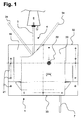
- the housing 1 shows a bottom view of the housing 1 of the line memory with a partially protruding supply line 4, which is designed to receive a tensile load. This can be realized, for example, in cables via a tensile forces receiving jacket.
- the housing 1 is composed of the housing pan 20 and the housing cover 19 bolted thereto. In the bottom view of Figure 1, the housing cover 19 is visible in three corners. For attachment of the line storage at the bottom of a semitrailer, not shown, the housing 1 on two opposite sides and on the rear side 33 mounting holes 21, which extend through the housing cover 19 and the housing pan 20 throughout.
- a front line section 5 can be seen in a partially pulled out of the housing 1 position.
- a trapezoidal tapered plug wedge 6 is mounted, which can be retracted into a complementarily shaped retraction opening of a fifth wheel and thereby, for example, allows an electrical connection.
- the front line section 5 is inserted into the plug wedge 6 and secured thereto tensile.
- the plug wedge 6 can pivot and the front line section 5 is pulled out of the housing 1.
- the maximum extraction travel is 850 mm for the line storage shown.
- two swivel-out positions 34 of the front line section 5 are shown by dashed lines.
- the rear line section 7 of the supply line 4 is led out of the housing 1.
- This rear line section 7 is decoupled from the pull-in and pull-out movements of the front line section 5.
- the rear line section 7 can therefore be connected in a simple manner to existing fixed lines on the semi-trailer.
- FIG. 2 shows a plan view of the line accumulator with the housing cover 19 removed.
- a rotatably mounted drum disc 2 on which the supply line 4 is partially wound.
- On the front side 32 of the front line section 5 of the supply line 4 occurs tangentially from a Drum jacket 8 out.
- the drum shell 8 is formed at the radial outer end of the drum disc 2 and serves exclusively to receive the front line section 5.
- the front line section 5 is largely wound.
- the front line section 5 is placed in the plan view in a clockwise direction on the drum shell 8 and in the shell breakthrough 9a recognizable.
- a line attachment 23 which fixes the supply line 4 fixed to the drum disk 2.
- the supply line 4 passes through the drum casing 8 and is spirally laid down on the drum disk 2 in the same winding direction as in the drum casing 8.
- the rear line section 7 is spirally turned upwards approximately twice and passes upwardly through a housing passage 25 through the housing cover 19, not shown in FIG.
- the supply line 4 into the front line section 5, which rests on the drum shell 8 and at least partially from the housing 1 (see Figure 1) can be pulled in and out, and divided into the rear line section 7, the is located on the drum plate 2 and outwardly fixed from the housing 1 (see Figure 1) is led out.
- a rubber sleeve 24 is inserted into the housing passage 25.
- the rear line section 7 is fastened to the housing cover 19 (see also FIG. 5) with a retaining clip 26.
- FIG. 3 shows a cross-section along the section line A-A shown in FIG.
- the housing 1 is composed of the housing pan 20 and the housing cover 19 fastened thereon, wherein the housing 1 is opened on its front side 32 and thereby permits pivoting of the front cable section 5 in accordance with the relative movement of the plug wedge 6 (see FIG.
- the drum shell 8 which is shaped with a fork-like groove profile 11, is shown, which completely surrounds the drum disk 2 in the circumferential direction.
- the drum casing 8 accommodates the front line section 5, which is wound in two layers over one another as a multiple winding 10 in a first plane on the drum casing 8.
- the drum disc 2 is concave on both sides and takes on the side of the housing cover 19 in a second plane, also wrapped in two layers, the rear line section 7.
- the front line section 5 of the line memory is in the representation of Figure 3 in a largely wound state.
- the turns of the spirally wound rear line section 7 migrate inwards.
- front line section 7 are located on the drum disk 2 three to four wraps, of which the inner can come to rest on a drum sleeve 29.
- a spring chamber 15 is formed below the drum plate 2, in which coaxial with the drum plate 2, a spring element 3 is arranged.
- the spring element 3 is a coil spring, which with a End fixed to the housing 1 and the opposite end to the drum plate 2 is fixed and ensures a defined restoring force of the drum plate 2.
- FIG. 4 shows an enlarged detail of the region marked Z in FIG. 3.
- the drum disk 2 can be seen, which is mounted centrally in a dome bearing 18 which extends between the housing pot 20 and the housing cover 19.
- An essential component of the Domlagers 18 is a bearing base 27, through which a retaining screw 22 is inserted.
- a nut 28 screwed from the side of the housing cover 19 the housing cover 19 and the housing trough 20 are screwed against each other, whereby the housing (see Fig. 3) experiences a high stability.
- the bearing base 27 serves as a stationary abutment for the bearing base 27 rotating drum pulley 2.
- the drum sleeve 29 is inserted and in turn a plain bearing 30 is pressed.
- the sliding bearing 30 thus rotates together with the drum disk 2 about the stationary bearing base 27th
- the groove profile 11 is formed as a U-profile and opened at the radially outer end for receiving the front line section 5.
- the U-profile has two parallel legs, which face each other with an opening 12.
- the opening width 12 is chosen only slightly larger than the diameter 13 of the supply line 4.
- the two legs of the U-shaped profile run together conically.
- the entire depth 14 of the groove profile 11 extends from the outer edge of the Drum shell 8 to the profile deepest 35, wherein substantially the portion of the mutually parallel legs of the U-profile for receiving the front line section 5 is suitable and should have at least one depth for receiving two superposed windings of the front line section 5.
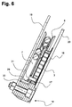
- FIG. 5 shows another cross-section through the line memory according to the section line C-C in FIG. 2.
- the discharge of the rear line section 7 from the housing 1 can be seen. 5, this is guided on the upper side 36 of the housing cover 19 in the direction of the rear side 33 by the exit passage 25, which is not shown in FIG.
- the retaining clip 26 is attached to the housing cover 19 for fixed fixation of the rear conduit section 7 on the upper side.
- FIG. 7 shows a top view exclusively of a drum disk 2.
- Centrally located in the drum disk 2 is a central bore 38 for receiving the mandrel bearing 18 (see FIG.
- the central bore 38 is completely surrounded by the sliding bearing 30, which is pressed into the integral with the drum disc 2 drum sleeve 29.
- the drum disk 2 In the immediate vicinity of the drum sleeve 29, the drum disk 2 has a further bore, the pin 31 as a pin holder 31 for fixing the coil spring. 3 receives.
- the drum shell 8 is further indicated.
- the drum disk 2 is shown in a cross section corresponding to the section line AA in FIG. 8 illustrates the symmetrical structure of the drum disk 2 from two shell-like halves, which are connected to one another in a material-locking manner via individual welding points 39b (see also FIG.
- the drum sleeve 29 is also firmly connected to the drum disc 2 with a peripheral weld 39a.
- the pin 31 protrudes from the drum disk 2 and the drum casing 8.
Abstract
Description
Die Erfindung betrifft einen Leitungsspeicher für eine Versorgungsleitung an einem Sattelauflieger mit einem Königszapfen und einem an dem Königszapfen schwenkbar gelagerten Steckerkeil.The invention relates to a line storage for a supply line to a semi-trailer with a kingpin and a swivel mounted on the kingpin plug wedge.
Das Ankuppeln eines Sattelaufliegers an einem Zugfahrzeug erfolgt in der Regel durch ein Zurückfahren des Zugfahrzeuges unter den Sattelauflieger, wodurch ein auf der Unterseite des Sattelaufliegers angeordneter Königszapfen mit einer auf dem Zugfahrzeug befindlichen Sattelkupplung in Eingriff gebracht und anschließend verriegelt wird. Zum Abkuppeln wird der Auflieger in bekannter Weise abgestellt, die Sattelkupplung geöffnet und das Zugfahrzeug vorgefahren. Zur Optimierung der Arbeitsbedingungen von Fernfahrern gibt es Bestrebungen, das An- und Abkuppeln des Sattelaufliegers und des Zugfahrzeuges zu automatisieren beziehungsweise diesen Vorgang aus dem Führerhaus des Zugfahrzeuges fernzusteuern. In Zusammenhang mit derartigen fernsteuerbaren Sattelkupplungen existieren bereits auch Systeme, die das Verbinden von Versorgungsleitungen zwischen Zugfahrzeug und Sattelauflieger automatisiert zusammen mit dem An- und Abkuppeln des Sattelaufliegers vornehmen. Unter Versorgungsleitungen werden in erster Linie Kabel zur Übertragung von elektrischer Energie aber auch pneumatische oder auch hydraulische Leitungen verstanden.The coupling of a semi-trailer to a towing vehicle is usually carried out by a retraction of the towing vehicle under the semi-trailer, whereby a arranged on the underside of the semi-trailer kingpin is engaged with a fifth wheel located on the towing vehicle and then locked. To uncouple the trailer is parked in a known manner, opened the fifth wheel and pulled up the towing vehicle. To optimize the working conditions of truckers, there are efforts to automate the coupling and uncoupling of the semi-trailer and towing vehicle or remotely control this process from the cab of the towing vehicle. In connection with such remote controlled fifth wheel couplings already exist systems that make the connection of supply lines between towing vehicle and semitrailer automated together with the coupling and uncoupling of the semitrailer. Under supply lines are understood primarily cables for the transmission of electrical energy but also pneumatic or hydraulic lines.
Ein bewährtes System zum Verbinden der Versorgungsleitungen durch ein Ankuppeln des Aufliegers umfasst einen schwenkbar an dem Königszapfen gelagerten Steckerkeil entsprechend der DE 101 55 056 A1, der sich beim Einfahren des Königszapfens in die Sattelkupplung in die keilförmig zulaufende Einfahröffnung einfügt, dort Steckkontakten gegenüberliegt und eine Kontaktierung ermöglicht. Bei Kurvenfahrten des Zugfahrzeugs wird der Steckerkeil in der Einfahröffnung formschlüssig fixiert und dreht gegenüber dem Auflieger. Aus diesem Grund ist es notwendig, die Versorgungsleitung aufliegerseitig in einer ausreichenden Länge bereitzustellen, um ein Abreißen der Versorgungsleitung zwischen dem Steckerkeil und dem Sattelauflieger auch bei enger Kurvenfahrt zu vermeiden. Der wesentliche und zu Systemausfällen führende Nachteil besteht darin, dass es bei Geradeausfahrt zu einem Durchhängen und einem damit verbundenen Risiko von Beschädigungen oder einem Abreißen der Versorgungsleitung kommt.A proven system for connecting the supply lines by coupling the trailer comprises a pivotally mounted on the kingpin plug wedge according to DE 101 55 056 A1, which is when retracting the kingpin in the fifth wheel in inserts the wedge-shaped tapered entry opening, there opposite plug contacts and allows a contact. When cornering the towing vehicle, the plug wedge is positively fixed in the entry opening and rotates relative to the trailer. For this reason, it is necessary to provide the supply line on the trailer side in a sufficient length to prevent tearing of the supply line between the plug wedge and the semi-trailer even in tight cornering. The essential disadvantage leading to system failures is that, when driving straight ahead, there is sagging and an associated risk of damage or tearing off of the supply line.
Um Beschädigungen an Verbindungsleitungen zwischen einem Zugfahrzeug und einem Auflieger zu vermeiden, sind aus dem Stand der Technik bereits so genannte Leitungsspeicher bekannt, die mit Hilfe einer federvorgespannten Kabeltrommel die Verbindungsleitung unter Zugspannung halten. Ein derartiger Leitungsspeicher ist beispielsweise in der DE 817 556 B offenbart und umfasst ein Gehäuse mit einer darin drehbar auf einer Hohlachse gelagerten Kabeltrommel. Die Verbindungsleitung wird in nicht angekuppeltem Zustand bis zu einem Anstoßen des Steckers an dem Gehäuse aufgewickelt. Der auf der Kabeltrommel aufgewickelte Teil ist mit einem durch die Hohlachse herausgeführten ortsfesten Kabelabschnitt über ein an beide Teile angeschlossenes Flachkabel verbunden. Diese Konstruktion hat sich jedoch unter der alltäglichen Belastung nicht als zuverlässig herausgestellt, da insbesondere die Verwendung von drei Kabelabschnitten mit zwei Verbindungsstellen zu Brüchen der Verbindung geführt hat.In order to avoid damage to connecting lines between a towing vehicle and a semi-trailer, so-called line memories are already known from the prior art, which hold the connecting line under tension with the aid of a spring-biased cable drum. Such a line memory is disclosed, for example, in DE 817 556 B and comprises a housing with a cable drum mounted rotatably on a hollow axle. The connecting line is wound up in uncoupled state until the plug is abutted against the housing. The wound on the cable drum part is connected to a led out through the hollow shaft fixed cable section via a connected to both parts flat cable. However, this design has not proven to be reliable under everyday stress, especially since the use of three cable sections with two connection points has led to breaks in the connection.
Aus diesem Grund lag der Erfindung die Aufgabe zugrunde, einen robusten Leitungsspeicher bereitzustellen, der auf mechanisch einfache Weise ein Durchhängen der Versorgungsleitung verhindert und andererseits für eine stetige Vorspannung der Versorgungsleitung sorgt.For this reason, the invention has for its object to provide a robust line memory, which is based on mechanically simple Way prevents sagging of the supply line and on the other hand ensures a steady bias of the supply line.
Die Aufgabe wird erfindungsgemäß mit einem Leitungsspeicher gelöst, der ein Gehäuse und eine in dem Gehäuse drehbar gelagerte Trommelscheibe umfasst, wobei die Trommelscheibe über ein Federelement vorgespannt ist und die Versorgungsleitung mit ihrem vorderen Leitungsabschnitt an dem Steckerkeil angreift und mit ihrem hinteren Leitungsabschnitt ortsfest aus dem Gehäuse herausgeführt ist.The object is achieved with a line storage, comprising a housing and a rotatably mounted in the housing drum pulley, the drum pulley is biased by a spring element and the supply line acts with its front line section on the plug wedge and stationary with its rear line section from the housing led out.
Bei Geradeausfahrt befindet sich die Versorgungsleitung in einem weitgehend eingerollten Zustand auf der Trommelscheibe, so dass die Versorgungsleitung einerseits gegen Beschädigungen hervorragend geschützt ist und andererseits die Vorspannung der Trommelscheibe ein Abwickeln der Versorgungsleitung bei einer Kurvenfahrt und einem Ausschwenken des Sattelaufliegers gegenüber der Zugmaschine erlaubt. Darüber hinaus befindet sich die Versorgungsleitung derart unter Spannung, dass bei einem Zurückschwenken des Sattelaufliegers am Ende der Kurvenfahrt keine Gefahr besteht, dass Teile der Versorgungsleitung zwischen dem Zugfahrzeug und dem Auflieger gequetscht werden.When driving straight ahead, the supply line is in a largely rolled-up state on the drum disc, so that the supply line is well protected against damage on the one hand and on the other hand allows the bias of the drum disc unwinding of the supply line when cornering and swinging of the semi-trailer relative to the tractor. In addition, the supply line is under tension so that when swinging back the semi-trailer at the end of cornering there is no danger that parts of the supply line between the towing vehicle and the semi-trailer are crushed.
Ein weiterer Vorteil des Leitungsspeichers liegt darin, dass der Steckerkeil auch bei Fahrten ohne Sattelauflieger aufgrund der Vorspannung der Versorgungsleitung stets in einer einfahrbereiten Stellung ausgerichtet ist. Dieses schließt das Risiko aus, bei einem erneuten Ankuppeln eines Sattelaufliegers mit der Sattelkupplung beziehungsweise deren keilförmiger Einfahröffnung vor einen falsch ausgerichteten Steckerkeil zu fahren und diesen dadurch zu zerstören.Another advantage of the line memory is that the plug wedge is always aligned even when driving without semi-trailer due to the bias of the supply line in a running-in position. This precludes the risk to drive in a renewed coupling of a semi-trailer with the fifth wheel or its wedge-shaped insertion opening in front of a misaligned plug wedge and destroy it thereby.
Aufgrund der flachen Ausbildung der Trommelscheibe kann der Leitungsspeicher insgesamt sehr flachbauend ausgeführt sein und dadurch zusammen mit dem Sattelauflieger bei Kurvenfahrten über das hintere Ende des Zugfahrzeugs hinwegschwenken.Due to the flat design of the drum pulley the line storage can be carried out overall very flat construction and thereby swing away along with the semi-trailer when cornering on the rear end of the towing vehicle.
Die oben stehende konstruktive Ausgestaltung weist eine einstückig durchgehende Versorgungsleitung auf, die sich von dem Steckerkeil bis zum Verlassen des Gehäuses beziehungsweise bis zu den Verbrauchern des Sattelaufliegers erstreckt. Hierdurch wird die betriebliche Verfügbarkeit gegenüber Systemen, die auf einer Drehübertragung beispielsweise mit Kontaktringen und Schleifbürsten basieren, erheblich gesteigert. Die letztgenannten sind aufgrund ihrer hohen Störanfälligkeit, hervorgerufen insbesondere durch eine feuchtigkeitsbedingte Korrosion, für einen Einsatz an der exponierten Position unter einem Sattelauflieger ungeeignet.The above constructive embodiment has an integrally continuous supply line extending from the plug wedge to the exit of the housing or to the consumers of the semitrailer. As a result, the operational availability compared to systems based on a rotary transmission, for example with contact rings and brushes, significantly increased. The latter are unsuitable for use at the exposed position under a semi-trailer because of their high susceptibility, caused in particular by a moisture-related corrosion.
Günstigerweise ist an dem radial äußeren Ende der Trommelscheibe ein Trommelmantel ausgeformt, auf welchen der vordere Leitungsabschnitt aufgelegt ist. Dieser Trommelmantel dient sowohl der Führung als auch der Aufnahme des aus dem Leitungsspeicher herausziehbaren vorderen Leitungsabschnitts.Conveniently, a drum shell is formed at the radially outer end of the drum disc, on which the front line section is placed. This drum shell serves both the leadership and the recording of the withdrawable from the line storage front pipe section.
Der hintere Leitungsabschnitt dagegen kann spiralartig auf die Trommelscheibe gelegt sein. Hierbei ist es besonders vorteilhaft, wenn der Trommelmantel einen Manteldurchbruch aufweist und die Versorgungsleitung an dem Manteldurchbruch ortsfest an der Trommelscheibe und/oder dem Trommelmantel befestigt ist. Bei dieser Ausführungsform wird die Versorgungsleitung durch die im Bereich des Manteldurchbruchs angeordnete Befestigung in einen vorderen Leitungsabschnitt, der vom Steckerkeil bis zu der Befestigung reicht, und einen hinteren Leitungsabschnitt, der von der Befestigung bis aus dem Gehäuse heraus reicht, unterteilt.The rear line section, however, can be placed spirally on the drum disk. It is particularly advantageous if the drum shell has a shell opening and the supply line is fixed to the shell breakthrough fixed to the drum disc and / or the drum shell. In this embodiment, the supply line is subdivided by the fastening arranged in the region of the jacket opening into a front line section, which extends from the plug wedge to the attachment, and a rear line section, which extends from the attachment to the housing.
Der vordere Leitungsabschnitt kann als Mehrfachwicklung auf den Trommelmantel aufgelegt sein. Bei den in der Praxis benötigten Ausziehlängen des vorderen Leitungsabschnitts haben sich 2 bis 3 übereinander liegende Wicklungen bewährt. Aufgrund der Mehrfachwicklung wird eine minimale Höhe des Trommelmantels benötigt.The front line section can be placed as a multiple winding on the drum shell. With the extraction lengths of the front line section required in practice, 2 to 3 windings lying one on top of each other have proved themselves. Due to the multiple winding a minimum height of the drum shell is required.
Um ein gleichmäßiges Auf- und Abwickeln des vorderen Leitungsabschnitts der Versorgungsleitung zu gewährleisten, sollte der Trommelmantel in Umfangsrichtung vollständig die Trommelscheibe umgeben.To ensure a uniform winding and unwinding of the front line section of the supply line, the drum shell in the circumferential direction should completely surround the drum disc.
Eine präzise Führung des vorderen Leitungsabschnitts wird erreicht, wenn der Trommelmantel als Rillenprofil, insbesondere als U-Profil, ausgebildet ist. Das U-Profil ist hinsichtlich seiner Form komplementär zu dem Querschnitt der Versorgungsleitung ausgeformt und schont damit den vorderen Leitungsabschnitt im Kontaktbereich zu dem Trommelmantel.A precise guidance of the front line section is achieved when the drum shell is designed as a groove profile, in particular as a U-profile. The U-profile is formed in terms of its shape complementary to the cross section of the supply line and thus protects the front line section in the contact area to the drum shell.
Das Rillenprofil oder das U-Profil sollte eine Öffnungsweite aufweisen, die geringfügig größer als der Durchmesser der Versorgungsleitung gewählt ist. Hierdurch werden Überläufer beim Aufwickeln vermieden.The groove profile or the U-profile should have an opening width that is slightly larger than the diameter of the supply line is selected. As a result, defections are avoided during winding.
Zur Aufnahme mehrerer übereinander liegender Wicklungen muss das Rillenprofil oder das U-Profil eine Tiefe aufweisen, die mindestens der Summe der Durchmesser der auf dem Trommelmantel aufliegenden Anzahl Wicklungen entspricht. Bevorzugt sollte die Profiltiefe mindestens dem doppelten Durchmesser der Versorgungsleitung entsprechen.To accommodate a plurality of superimposed windings, the groove profile or the U-profile must have a depth which corresponds at least to the sum of the diameters of the number of windings resting on the drum shell. Preferably, the tread depth should be at least twice the diameter of the supply line.
Vorteilhafterweise ist das Federelement eine Spiralfeder. Diese kann in einem Federraum angeordnet sein, der von der Versorgungsleitung durch die Trommelscheibe abgegrenzt ist. Aus dieser Anordnung ergibt sich, dass auf der Trommelscheibe die Versorgungsleitung, beispielsweise dessen hinterer Leitungsabschnitt, und unterhalb der Trommelscheibe die Spiralfeder angeordnet ist. In einer alternativen Ausführungsform kann auch die Spiralfeder auf der Trommelscheibe angeordnet sein und die Versorgungsleitung auf der Innenseite des Gehäuses unterhalb der Trommelscheibe liegen.Advantageously, the spring element is a spiral spring. This can be arranged in a spring chamber which is delimited by the supply line through the drum disc. From this arrangement it follows that the supply line, for example, the rear line section, and below the drum disk, the spiral spring is arranged on the drum pulley. In an alternative embodiment, the coil spring may also be arranged on the drum disk and the supply line on the inside of the housing lie below the drum disk.
In einer günstigen Ausführungsform ist die Spiralfeder mit ihrem ersten Ende ortsfest an dem Gehäuse befestigt und greift mit ihrem zweiten Ende an der Trommelscheibe und/oder dem Trommelmantel an. Besonders vorteilhaft ist es, wenn das erste Ende in radialer Richtung außen an dem Gehäuse befestigt ist und das zweite Ende innen an der Trommelscheibe angreift.In a favorable embodiment, the coil spring is fixedly attached with its first end to the housing and engages with its second end to the drum disc and / or the drum shell. It is particularly advantageous if the first end is fixed in the radial direction on the outside of the housing and the second end engages on the inside of the drum disk.
Eine stabile Ausgestaltung des Leitungsspeichers lässt sich realisieren, in dem die Trommelscheibe an einem ortsfest in dem Gehäuse stehenden Domlager gelagert ist. Das Domlager kann sich dann vollständig durch das Gehäuse erstrecken und das Gehäuse dadurch stabilisieren sowie eine stabile Lagerung der Trommelscheibe ermöglichen.A stable embodiment of the line memory can be realized, in which the drum disk is mounted on a stationary in the housing housing. The dome bearing can then extend completely through the housing and thereby stabilize the housing and allow stable storage of the drum disc.
Die Erfindung wird zum besseren Verständnis anhand der nachfolgenden acht Zeichnungsfiguren näher erläutert. Dabei zeigen die
- Fig. 1:
- eine Unteransicht auf den Leitungsspeicher;
- Fig. 2:
- eine Draufsicht auf den Leitungsspeicher mit abgenommenem Gehäusedeckel;
- Fig. 3:
- einen Querschnitt längs der Schnittlinie A-A gemäß Fig. 2;
- Fig. 4:
- einen vergrößerten Ausschnitt Z gemäß Fig. 3;
- Fig. 5:
- einen Querschnitt längs der Schnittlinie C-C gemäß Fig. 2;
- Fig. 6:
- einen Vergrößerten Ausschnitt gemäß Fig. 5;
- Fig. 7:
- eine Draufsicht auf eine Trommelscheibe ohne Versorgungsleitung und
- Fig. 8:
- einen Querschnitt auf die Trommelscheibe längs der Schnittlinie A-A in Fig. 7.
- Fig. 1:
- a bottom view of the line memory;
- Fig. 2:
- a plan view of the line storage with removed housing cover;
- 3:
- a cross section along the section line AA of FIG. 2;
- 4:
- an enlarged section Z of FIG. 3;
- Fig. 5:
- a cross section along the section line CC of FIG. 2;
- Fig. 6:
- a magnified section of FIG. 5;
- Fig. 7:
- a top view of a drum disc without supply line and
- Fig. 8:
- a cross section of the drum disk along the section line AA in Fig. 7.
Die Figur 1 zeigt eine Unteransicht auf das Gehäuse 1 des Leitungsspeichers mit einer teilweise herausragenden Versorgungsleitung 4, die zur Aufnahme einer Zugbelastung ausgelegt ist. Dieses kann beispielsweise bei Kabeln über einen Zugkräfte aufnehmenden Mantel realisiert werden. Das Gehäuse 1 setzt sich aus der Gehäusewanne 20 und dem damit verschraubten Gehäusedeckel 19 zusammen. In der Unteransicht der Figur 1 ist der Gehäusedeckel 19 in drei Eckbereichen sichtbar. Zur Befestigung des Leitungsspeichers an der Unterseite eines nicht gezeigten Aufliegers weist das Gehäuse 1 an zwei gegenüberliegenden Seiten und an der Hinterseite 33 Befestigungslöcher 21 auf, die sich durchgehend durch den Gehäusedeckel 19 und die Gehäusewanne 20 erstrecken.1 shows a bottom view of the
In Richtung der Vorderseite 32 ist ein vorderer Leitungsabschnitt 5 in einer teilweise aus dem Gehäuse 1 herausgezogenen Position zu erkennen. Am Ende des vorderen Leitungsabschnitts 5 ist ein trapezartig zulaufender Steckerkeil 6 angebracht, der in eine komplementär ausgeformte Einfahröffnung einer Sattelkupplung eingefahren werden kann und dadurch beispielsweise eine elektrische Verbindung ermöglicht. Der vordere Leitungsabschnitt 5 ist in den Steckerkeil 6 eingeführt und zugfest an diesem befestigt.In the direction of the
Bei einer Kurvenfahrt des nicht gezeigten Zugfahrzeuges kommt es zu einem Ausschwenken des Aufliegers gegenüber dem Zugfahrzeug. In diesem Fall kann der Steckerkeil 6 mitschwenken und der vordere Leitungsabschnitt 5 wird aus dem Gehäuse 1 herausgezogen. Der maximale Ausziehweg beträgt bei dem gezeigten Leitungsspeicher 850 mm. Beispielhaft sind mit gestrichelten Linien zwei Ausschwenkstellungen 34 des vorderen Leitungsabschnitts 5 dargestellt.When cornering the towing vehicle, not shown, there is a swinging out of the trailer relative to the towing vehicle. In this case, the
Auf der Hinterseite 33 des Gehäuses 1 ist der hintere Leitungsabschnitt 7 der Versorgungsleitung 4 aus dem Gehäuse 1 herausgeführt. Dieser hintere Leitungsabschnitt 7 ist entkoppelt von Ein- und Ausziehbewegungen des vorderen Leitungsabschnitts 5. Der hintere Leitungsabschnitt 7 kann deshalb auf einfache Weise mit auf dem Sattelauflieger vorhandenen ortsfest verlegten Leitungen verbunden werden.On the
Die Figur 2 zeigt eine Draufsicht auf den Leitungsspeicher mit abgenommenem Gehäusedeckel 19. In einem mittleren Bereich der Gehäusewanne 20 befindet sich eine drehbar gelagerte Trommelscheibe 2 auf der die Versorgungsleitung 4 teilweise aufgewickelt ist. Auf der Vorderseite 32 tritt der vordere Leitungsabschnitt 5 der Versorgungsleitung 4 tangential aus einem Trommelmantel 8 heraus. Der Trommelmantel 8 ist an dem radialen äußeren Ende der Trommelscheibe 2 ausgeformt und dient ausschließlich der Aufnahme des vorderen Leitungsabschnitts 5. Bei dem in der Figur 2 dargestellten Leitungsspeicher ist der vordere Leitungsabschnitt 5 weitgehend aufgewickelt.FIG. 2 shows a plan view of the line accumulator with the
Der vordere Leitungsabschnitt 5 ist in der Draufsicht im Uhrzeigersinn auf den Trommelmantel 8 aufgelegt und in dem Manteldurchbruch 9a erkennbar. Unmittelbar innerhalb des Manteldurchbruchs 9a befindet sich eine Leitungsbefestigung 23, welche die Versorgungsleitung 4 ortsfest zu der Trommelscheibe 2 fixiert. In einem zweiten Manteldurchbruch 9b stößt die Versorgungsleitung 4 durch den Trommelmantel 8 hindurch und ist im gleichen Wickelsinn wie im Trommelmantel 8 auf der Trommelscheibe 2 spiralartig abgelegt. Der hintere Leitungsabschnitt 7 ist nach innen ca. zweimal spiralartig aufgedreht und tritt nach oben durch eine Gehäusedurchführung 25 durch den in der Figur 2 nicht gezeigten Gehäusedeckel 19 hindurch.The
Ausgehend von dieser Leitungsbefestigung 23 wird die Versorgungsleitung 4 in den vorderen Leitungsabschnitt 5, der auf dem Trommelmantel 8 aufliegt und zumindest teilweise aus dem Gehäuse 1 (s. Figur 1) ein- und ausgezogen werden kann, und in den hinteren Leitungsabschnitt 7 unterteilt, der auf der Trommelscheibe 2 liegt und nach außen ortsfest aus dem Gehäuse 1 (s. Figur 1) herausgeführt ist.Starting from this
Zur Abdichtung und um Beschädigungen an dem hinteren Leitungsabschnitt 7 durch Scheuerstellen im Bereich der Gehäusedurchführung 25 zu vermeiden, ist in die Gehäusedurchführung 25 eine Gummimuffe 24 eingesetzt. Darüber hinaus ist der hintere Leitungsabschnitt 7 auf dem Gehäusedeckel 19 (s. auch Figur 5) mit einer Halteschelle 26 befestigt.For sealing and to avoid damage to the
Die Figur 3 zeigt einen Querschnitt längs der in Figur 2 eingezeichneten Schnittlinie A-A. Das Gehäuse 1 setzt sich aus der Gehäusewanne 20 und dem darauf befestigten Gehäusedeckel 19 zusammen, wobei das Gehäuse 1 auf seiner Vorderseite 32 geöffnet ist und dadurch ein Schwenken des vorderen Leitungsabschnitts 5 entsprechend der Relativbewegung des Steckerkeils 6 (s. Figur 1) zulässt.FIG. 3 shows a cross-section along the section line A-A shown in FIG. The
In dem äußeren Bereich der Trommelscheibe 2 ist der mit einem gabelartigen Rillenprofil 11 geformte Trommelmantel 8 zu sehen, der in Umfangsrichtung vollständig die Trommelscheibe 2 umgibt. Der Trommelmantel 8 nimmt den vorderen Leitungsabschnitt 5 auf, der zweilagig übereinander als Mehrfachwicklung 10 in einer ersten Ebene auf dem Trommelmantel 8 aufgewickelt ist.In the outer region of the
Innerhalb des Trommelmantels 8 ist die Trommelscheibe 2 beidseitig konkav ausgeformt und nimmt auf der Seite des Gehäusedeckels 19 in einer zweiten Ebene, ebenfalls zweilagig ineinander gewickelt, den hinteren Leitungsabschnitt 7 auf. Der vordere Leitungsabschnitt 5 des Leitungsspeichers befindet sich in der Darstellung der Figur 3 in einem weitgehend aufgewickelten Zustand. Während des Herausziehens des vorderen Leitungsabschnitts 5 und einer daraus resultierenden Drehbewegung der Trommelscheibe 2 wandern die Windungen der spiralartig aufgewickelten hinteren Leitungsabschnitts 7 nach innen. Bei einem vollständig herausgezogenen vorderen Leitungsabschnitt 7 befinden sich auf der Trommelscheibe 2 drei bis vier Umschlingungen, von denen die innen liegende an einer Trommelhülse 29 zur Anlage kommen kann.Within the
Auf der Seite der Gehäusewanne 20 ist unterhalb der Trommelscheibe 2 ein Federraum 15 ausgebildet, in welchem koaxial zu der Trommelscheibe 2 ein Federelement 3 angeordnet ist. Bei dem Federelement 3 handelt es sich um eine Spiralfeder, die mit einem Ende ortsfest an dem Gehäuse 1 und dem gegenüberliegenden Ende an der Trommelscheibe 2 befestigt ist und für eine definierte Rückstellkraft der Trommelscheibe 2 sorgt.On the side of the
Die Figur 4 stellt einen vergrößerten Ausschnitt des in Figur 3 mit Z gekennzeichneten Bereiches dar. Hierbei ist die Trommelscheibe 2 zu erkennen, die zentrisch in einem Domlager 18 gelagert ist, welches sich zwischen der Gehäusewanne 20 und dem Gehäusedeckel 19 erstreckt. Ein wesentliches Bauteil des Domlagers 18 ist ein Lagersockel 27, durch den eine Halteschraube 22 gesteckt ist. Mit Hilfe einer von der Seite des Gehäusedeckels 19 aufgeschraubten Mutter 28 wird der Gehäusedeckel 19 und die Gehäusewanne 20 gegeneinander verschraubt, wodurch das Gehäuse (s. Fig. 3) eine hohe Stabilität erfährt.FIG. 4 shows an enlarged detail of the region marked Z in FIG. 3. Here, the
Gleichzeitig dient der Lagersockel 27 als stehendes Widerlager für die um den Lagersockel 27 rotierende Trommelscheibe 2. Für einen verschleißarmen Betrieb und eine günstige Lasteinleitung ist zentrisch in der Trommelscheibe 2 die Trommelhülse 29 eingesetzt und in diese wiederum ein Gleitlager 30 eingepresst. Das Gleitlager 30 dreht demzufolge zusammen mit der Trommelscheibe 2 um den stehenden Lagersockel 27.At the same time, the bearing
Darüber hinaus ist in der Figur 4 die Ausbildung des Trommelmantels 8 verdeutlicht. Das Rillenprofil 11 ist als U-Profil ausgeformt und an dem radial äußeren Ende zur Aufnahme des vorderen Leitungsabschnitts 5 geöffnet. Dabei weist das U-Profil zwei parallele Schenkel auf, die sich mit einer Öffnungsweite 12 gegenüberstehen. Die Öffnungsweite 12 ist nur geringfügig größer gewählt als der Durchmesser 13 der Versorgungsleitung 4. In dem Bereich des Profiltiefsten 35 laufen die beiden Schenkel des U-Profils konisch zusammen. Die gesamte Tiefe 14 des Rillenprofils 11 erstreckt sich vom äußeren Rand des Trommelmantels 8 bis zum Profiltiefsten 35, wobei im Wesentlichen der Abschnitt der parallel zueinander stehenden Schenkel des U-Profils für die Aufnahme des vorderen Leitungsabschnitts 5 geeignet ist und mindestens eine Tiefe zur Aufnahme von zwei übereinander liegenden Wicklungen des vorderen Leitungsabschnitts 5 aufweisen sollte.In addition, the embodiment of the
Die Figur 5 zeigt einen anderen Querschnitt durch den Leitungsspeicher gemäß der Schnittlinie C-C in Figur 2. Hierbei ist die Abführung des hinteren Leitungsabschnitts 7 aus dem Gehäuse 1 zu erkennen. Diese wird nach dem in Figur 5 nicht dargestellten Austritt durch die Gehäusedurchführung 25 (s. Figur 3) auf der Oberseite 36 des Gehäusedeckels 19 in Richtung der Hinterseite 33 geführt. Hierzu ist zur ortsfesten Fixierung des hinteren Leitungsabschnitts 7 auf der Oberseite 36 an dem Gehäusedeckel 19 die Halteschelle 26 angebracht.FIG. 5 shows another cross-section through the line memory according to the section line C-C in FIG. 2. Here, the discharge of the
In der Figur 6 ist ausschnittsweise der Leitungsspeicher in der Ansicht der Figur 5 vergrößert dargestellt. Besonders gut ist darin die Befestigung des als Spiralfeder geformten Federelementes 3 an der Trommelscheibe 2 mittels eines Stiftes 31 zu erkennen. Die Spiralfeder 3 hintergreift mit ihrem zweiten Ende 17 den Stift 31 und ist mit ihrem ersten Ende 16 an der Gehäusewanne 20 befestigt.In the figure 6 the detail of the line memory in the view of Figure 5 is shown enlarged. The attachment of the
Die Figur 7 stellt eine Draufsicht ausschließlich auf eine Trommelscheibe 2 dar. Zentrisch befindet sich in der Trommelscheibe 2 eine Mittelbohrung 38 zur Aufnahme des Domlagers 18 (s. Figur 4). Die Mittelbohrung 38 ist vollumfänglich von dem Gleitlager 30 umgeben, welches in die einstückig mit der Trommelscheibe 2 verbundene Trommelhülse 29 eingepresst ist. In unmittelbarer Nähe zu der Trommelhülse 29 weist die Trommelscheibe 2 eine weitere Bohrung auf, die als Stiftaufnahme 37 den Stift 31 zum Fixieren der Spiralfeder 3 aufnimmt. Im Randbereich der Trommelscheibe 2 ist ferner der Trommelmantel 8 angedeutet.7 shows a top view exclusively of a
In der Figur 8 ist die Trommelscheibe 2 in einem Querschnitt entsprechend der Schnittlinie A-A in Figur 7 gezeigt. Die Figur 8 verdeutlicht den symmetrischen Aufbau der Trommelscheibe 2 aus zwei schalenartigen Hälften, die über einzelne Schweißpunkte 39b (s. auch Figur 7) stoffschlüssig miteinander verbunden sind. Die Trommelhülse 29 ist ebenfalls mit einer umlaufenden Schweißnaht 39a mit der Trommelscheibe 2 fest verbunden. In der Figur 8 tritt der Stift 31 gegenüber der Trommelscheibe 2 und dem Trommelmantel 8 hervor.In FIG. 8, the
- 11
- Gehäusecasing
- 22
- Trommelscheibedrum washer
- 33
- Federelement, SpiralfederSpring element, spiral spring
- 44
- Versorgungsleitungsupply line
- 55
- Vorderer LeitungsabschnittFront pipe section
- 66
- Steckerkeilplug wedge
- 77
- Hinterer LeitungsabschnittRear line section
- 88th
- Trommelmanteldrum shell
- 9a, 9b9a, 9b
- ManteldurchbruchCoat breakthrough
- 1010
- MehrfachwicklungMultiple winding
- 1111
- Rillenprofilgroove profile
- 1212
- Öffnungsweite RillenprofilOpening width groove profile
- 1313
- Durchmesser VersorgungsleitungDiameter supply line
- 1414
- Tiefe Rillenprofil, ProfiltiefeDeep groove profile, tread depth
- 1515
- Federraumspring chamber
- 1616
- erstes Ende Spiralfederfirst end coil spring
- 1717
- zweites Ende Spiralfedersecond end coil spring
- 1818
- DomlagerDomlager
- 1919
- Gehäusedeckelhousing cover
- 2020
- Gehäusewannehousing trough
- 2121
- Befestigungslöchermounting holes
- 2222
- Halteschrauberetention screw
- 2323
- Leitungsbefestigungline mounting
- 2424
- Gummimuffegrommet
- 2525
- GehäusedurchführungHousing bushing
- 2626
- HalteschelleSupporting collar
- 2727
- Lagersockelbearing socket
- 2828
- Muttermother
- 2929
- Trommelhülsedrum sleeve
- 3030
- Gleitlagerbearings
- 3131
- Stiftpen
- 3232
- Vorderseite GehäuseFront housing
- 3333
- Hinterseite GehäuseRear housing
- 3434
- Ausschwenkstellungswung
- 3535
- Profiltiefstesprofile Deepest
- 3636
- Oberseite GehäusedeckelTop of housing cover
- 3737
- Stiftaufnahmepin receptacle
- 3838
- Mittelbohrungcenter bore
- 39a39a
- SchweißnahtWeld
- 39b39b
- Schweißpunktewelds
Claims (16)
Applications Claiming Priority (1)
| Application Number | Priority Date | Filing Date | Title |
|---|---|---|---|
| DE102004044992A DE102004044992B4 (en) | 2004-09-16 | 2004-09-16 | line memory |
Publications (3)
| Publication Number | Publication Date |
|---|---|
| EP1638174A2 true EP1638174A2 (en) | 2006-03-22 |
| EP1638174A3 EP1638174A3 (en) | 2007-12-05 |
| EP1638174B1 EP1638174B1 (en) | 2016-02-17 |
Family
ID=35336641
Family Applications (1)
| Application Number | Title | Priority Date | Filing Date |
|---|---|---|---|
| EP05019521.3A Active EP1638174B1 (en) | 2004-09-16 | 2005-09-08 | Cable storage |
Country Status (4)
| Country | Link |
|---|---|
| US (1) | US7472858B2 (en) |
| EP (1) | EP1638174B1 (en) |
| CA (1) | CA2519516C (en) |
| DE (1) | DE102004044992B4 (en) |
Cited By (2)
| Publication number | Priority date | Publication date | Assignee | Title |
|---|---|---|---|---|
| CN101112855B (en) * | 2006-07-18 | 2011-02-02 | 约斯特-韦尔克有限公司 | Pipeline branch of saddle type semitrailer truck |
| WO2021115866A1 (en) * | 2019-12-13 | 2021-06-17 | Igus Gmbh | Winding drum and torsion spring for a winding drum |
Families Citing this family (7)
| Publication number | Priority date | Publication date | Assignee | Title |
|---|---|---|---|---|
| US9327938B2 (en) | 2013-02-14 | 2016-05-03 | Haworth, Inc. | Cable retractor |
| KR101558978B1 (en) * | 2015-06-18 | 2015-10-13 | (주)금오전자 | Cable withdraw unit assembly |
| DE102018106676B3 (en) | 2018-03-21 | 2019-07-04 | Saf-Holland Gmbh | System and method for pivoting a coupling component |
| DE102018106677B3 (en) * | 2018-03-21 | 2019-06-19 | Saf-Holland Gmbh | System and method for pivoting a coupling component |
| SE544962C2 (en) * | 2020-12-03 | 2023-02-14 | Scania Cv Ab | An apparatus comprising an interface for providing an electrical connection between two vehicles |
| DE102021004253A1 (en) | 2021-08-20 | 2023-02-23 | Jost-Werke Deutschland Gmbh | wiring device |
| CH719507A2 (en) * | 2022-03-16 | 2023-09-29 | Alligator Ag | Coupling device for supply lines, in particular for conveying media from a tractor unit to a semi-trailer. |
Citations (8)
| Publication number | Priority date | Publication date | Assignee | Title |
|---|---|---|---|---|
| DE817556C (en) * | 1950-08-31 | 1951-10-18 | Heinrich Weidemann | Device for connecting electrical connection cables to motor vehicles and trailers |
| DE955334C (en) * | 1952-10-29 | 1957-01-03 | Demag Zug Gmbh | Device for the current transfer to one of two parts that can be rotated to a limited extent around the same vertical axis, especially for lifting equipment |
| US3773987A (en) * | 1972-02-07 | 1973-11-20 | R Davis | Cable retractor |
| US4417703A (en) * | 1981-11-19 | 1983-11-29 | Weinhold Dennis G | Quick retrieve cord reel |
| US5129828A (en) * | 1991-04-15 | 1992-07-14 | Bass Chauncie L | Rewind trailer light connector |
| JP2000085639A (en) * | 1998-09-14 | 2000-03-28 | Mitsubishi Motors Corp | Jumper cable winding device |
| DE10155056A1 (en) * | 2001-11-09 | 2003-06-05 | Jaeger Erich Gmbh & Co Kg | Plug-in coupling system for connecting lines of two vehicles |
| US6616080B1 (en) * | 1999-04-28 | 2003-09-09 | Speculative Product Design, Inc. | Retractable cord device |
Family Cites Families (4)
| Publication number | Priority date | Publication date | Assignee | Title |
|---|---|---|---|---|
| US4010913A (en) * | 1971-10-01 | 1977-03-08 | Ametek, Inc. | Retriever reel |
| US4053118A (en) * | 1976-05-21 | 1977-10-11 | Swing-Shift Mfg. Co. | Reversible reel unit |
| JP3461465B2 (en) * | 1999-06-18 | 2003-10-27 | 矢崎総業株式会社 | Wire harness winding device |
| US7172150B1 (en) * | 2002-07-26 | 2007-02-06 | Independent Solutions, Inc. | Retractable reel apparatus |
-
2004
- 2004-09-16 DE DE102004044992A patent/DE102004044992B4/en not_active Expired - Fee Related
-
2005
- 2005-09-08 EP EP05019521.3A patent/EP1638174B1/en active Active
- 2005-09-14 CA CA2519516A patent/CA2519516C/en active Active
- 2005-09-15 US US11/227,932 patent/US7472858B2/en active Active
Patent Citations (8)
| Publication number | Priority date | Publication date | Assignee | Title |
|---|---|---|---|---|
| DE817556C (en) * | 1950-08-31 | 1951-10-18 | Heinrich Weidemann | Device for connecting electrical connection cables to motor vehicles and trailers |
| DE955334C (en) * | 1952-10-29 | 1957-01-03 | Demag Zug Gmbh | Device for the current transfer to one of two parts that can be rotated to a limited extent around the same vertical axis, especially for lifting equipment |
| US3773987A (en) * | 1972-02-07 | 1973-11-20 | R Davis | Cable retractor |
| US4417703A (en) * | 1981-11-19 | 1983-11-29 | Weinhold Dennis G | Quick retrieve cord reel |
| US5129828A (en) * | 1991-04-15 | 1992-07-14 | Bass Chauncie L | Rewind trailer light connector |
| JP2000085639A (en) * | 1998-09-14 | 2000-03-28 | Mitsubishi Motors Corp | Jumper cable winding device |
| US6616080B1 (en) * | 1999-04-28 | 2003-09-09 | Speculative Product Design, Inc. | Retractable cord device |
| DE10155056A1 (en) * | 2001-11-09 | 2003-06-05 | Jaeger Erich Gmbh & Co Kg | Plug-in coupling system for connecting lines of two vehicles |
Cited By (2)
| Publication number | Priority date | Publication date | Assignee | Title |
|---|---|---|---|---|
| CN101112855B (en) * | 2006-07-18 | 2011-02-02 | 约斯特-韦尔克有限公司 | Pipeline branch of saddle type semitrailer truck |
| WO2021115866A1 (en) * | 2019-12-13 | 2021-06-17 | Igus Gmbh | Winding drum and torsion spring for a winding drum |
Also Published As
| Publication number | Publication date |
|---|---|
| CA2519516A1 (en) | 2006-03-16 |
| US20060054728A1 (en) | 2006-03-16 |
| EP1638174A3 (en) | 2007-12-05 |
| EP1638174B1 (en) | 2016-02-17 |
| US7472858B2 (en) | 2009-01-06 |
| CA2519516C (en) | 2013-11-12 |
| DE102004044992B4 (en) | 2010-04-29 |
| DE102004044992A1 (en) | 2006-04-06 |
Similar Documents
| Publication | Publication Date | Title |
|---|---|---|
| EP1638174B1 (en) | Cable storage | |
| EP1753652B1 (en) | Plug-in connections | |
| DE19836196C2 (en) | Power connection | |
| DE102006057308B4 (en) | Line fixing part | |
| DE102006050708B4 (en) | Electrical ribbon cable | |
| DE69723492T2 (en) | Line donor and donation process | |
| EP2952368A2 (en) | Trailer coupling | |
| DE202016102087U1 (en) | Wiring system for at least one up and downable supply line and rotation guide for this | |
| DE60014874T2 (en) | CHAIN-LIKE CONTAINER WITH A HOLDING DEVICE FOR A HASPEL WITH A HANDLED ELECTRICAL PIPE OR SIMILAR STRUCTURED MATERIAL THAT CAN BE HANDLED FROM THE HASPEL | |
| EP3891051B1 (en) | Kingpin arrangement | |
| DE19852975A1 (en) | Tension reducer to relieve traction force of safety belt rolling-up device | |
| EP2043904B1 (en) | External line connection for a semitrailer of a semitrailer truck | |
| DE102014109270B4 (en) | Cable fixation, plug with a cable fixation and method for fixing an electrical cable to a plug | |
| DE1763883C3 (en) | Brush holder | |
| EP1985502A1 (en) | Cable duct in the drive unit of an industrial truck with a tiller | |
| WO2006074731A1 (en) | Device for maintaining a detachable part on an object | |
| EP1667284A1 (en) | Contact device for a cable shield | |
| DE10107965B4 (en) | Towing device for a vehicle with a drawbar | |
| DE202017107461U1 (en) | Device for positionally correct fastening of an antenna arrangement | |
| DE102014006201A1 (en) | Cable lug, in particular for a motor vehicle | |
| EP0814542B1 (en) | Electrical socket | |
| DE102018100025A1 (en) | Device for transferring a line between a retracted state and an extended state and corresponding system, corresponding use and corresponding method | |
| DE3144058C2 (en) | Mobile cable storage | |
| DE102009050932A1 (en) | Trailer coupling device for motor vehicle, has ball neck, by which ball head is supported, where receiver opening is provided in area of ball head | |
| EP3369990A1 (en) | Cable reel |
Legal Events
| Date | Code | Title | Description |
|---|---|---|---|
| PUAI | Public reference made under article 153(3) epc to a published international application that has entered the european phase |
Free format text: ORIGINAL CODE: 0009012 |
|
| AK | Designated contracting states |
Kind code of ref document: A2 Designated state(s): AT BE BG CH CY CZ DE DK EE ES FI FR GB GR HU IE IS IT LI LT LU LV MC NL PL PT RO SE SI SK TR |
|
| AX | Request for extension of the european patent |
Extension state: AL BA HR MK YU |
|
| PUAL | Search report despatched |
Free format text: ORIGINAL CODE: 0009013 |
|
| AK | Designated contracting states |
Kind code of ref document: A3 Designated state(s): AT BE BG CH CY CZ DE DK EE ES FI FR GB GR HU IE IS IT LI LT LU LV MC NL PL PT RO SE SI SK TR |
|
| AX | Request for extension of the european patent |
Extension state: AL BA HR MK YU |
|
| RIC1 | Information provided on ipc code assigned before grant |
Ipc: H01R 13/72 20060101AFI20071031BHEP |
|
| RAP1 | Party data changed (applicant data changed or rights of an application transferred) |
Owner name: JOST-WERKE GMBH |
|
| 17P | Request for examination filed |
Effective date: 20080209 |
|
| AKX | Designation fees paid |
Designated state(s): AT BE BG CH CY CZ DE DK EE ES FI FR GB GR HU IE IS IT LI LT LU LV MC NL PL PT RO SE SI SK TR |
|
| 17Q | First examination report despatched |
Effective date: 20100423 |
|
| REG | Reference to a national code |
Ref country code: DE Ref legal event code: R079 Ref document number: 502005015111 Country of ref document: DE Free format text: PREVIOUS MAIN CLASS: H01R0013600000 Ipc: H01R0013720000 |
|
| GRAP | Despatch of communication of intention to grant a patent |
Free format text: ORIGINAL CODE: EPIDOSNIGR1 |
|
| RIC1 | Information provided on ipc code assigned before grant |
Ipc: B65H 75/42 20060101ALI20150903BHEP Ipc: B62D 53/12 20060101ALI20150903BHEP Ipc: H01R 13/72 20060101AFI20150903BHEP Ipc: B65H 75/44 20060101ALI20150903BHEP Ipc: B60D 1/62 20060101ALI20150903BHEP Ipc: H02G 11/02 20060101ALI20150903BHEP |
|
| INTG | Intention to grant announced |
Effective date: 20150918 |
|
| GRAS | Grant fee paid |
Free format text: ORIGINAL CODE: EPIDOSNIGR3 |
|
| GRAA | (expected) grant |
Free format text: ORIGINAL CODE: 0009210 |
|
| AK | Designated contracting states |
Kind code of ref document: B1 Designated state(s): AT BE BG CH CY CZ DE DK EE ES FI FR GB GR HU IE IS IT LI LT LU LV MC NL PL PT RO SE SI SK TR |
|
| REG | Reference to a national code |
Ref country code: GB Ref legal event code: FG4D Free format text: NOT ENGLISH |
|
| REG | Reference to a national code |
Ref country code: CH Ref legal event code: EP |
|
| REG | Reference to a national code |
Ref country code: IE Ref legal event code: FG4D Free format text: LANGUAGE OF EP DOCUMENT: GERMAN |
|
| REG | Reference to a national code |
Ref country code: AT Ref legal event code: REF Ref document number: 776019 Country of ref document: AT Kind code of ref document: T Effective date: 20160315 |
|
| REG | Reference to a national code |
Ref country code: DE Ref legal event code: R096 Ref document number: 502005015111 Country of ref document: DE |
|
| REG | Reference to a national code |
Ref country code: SE Ref legal event code: TRGR |
|
| REG | Reference to a national code |
Ref country code: LT Ref legal event code: MG4D |
|
| REG | Reference to a national code |
Ref country code: NL Ref legal event code: FP |
|
| PG25 | Lapsed in a contracting state [announced via postgrant information from national office to epo] |
Ref country code: GR Free format text: LAPSE BECAUSE OF FAILURE TO SUBMIT A TRANSLATION OF THE DESCRIPTION OR TO PAY THE FEE WITHIN THE PRESCRIBED TIME-LIMIT Effective date: 20160518 Ref country code: ES Free format text: LAPSE BECAUSE OF FAILURE TO SUBMIT A TRANSLATION OF THE DESCRIPTION OR TO PAY THE FEE WITHIN THE PRESCRIBED TIME-LIMIT Effective date: 20160217 Ref country code: FI Free format text: LAPSE BECAUSE OF FAILURE TO SUBMIT A TRANSLATION OF THE DESCRIPTION OR TO PAY THE FEE WITHIN THE PRESCRIBED TIME-LIMIT Effective date: 20160217 |
|
| PG25 | Lapsed in a contracting state [announced via postgrant information from national office to epo] |
Ref country code: PT Free format text: LAPSE BECAUSE OF FAILURE TO SUBMIT A TRANSLATION OF THE DESCRIPTION OR TO PAY THE FEE WITHIN THE PRESCRIBED TIME-LIMIT Effective date: 20160617 Ref country code: LV Free format text: LAPSE BECAUSE OF FAILURE TO SUBMIT A TRANSLATION OF THE DESCRIPTION OR TO PAY THE FEE WITHIN THE PRESCRIBED TIME-LIMIT Effective date: 20160217 Ref country code: PL Free format text: LAPSE BECAUSE OF FAILURE TO SUBMIT A TRANSLATION OF THE DESCRIPTION OR TO PAY THE FEE WITHIN THE PRESCRIBED TIME-LIMIT Effective date: 20160217 Ref country code: LT Free format text: LAPSE BECAUSE OF FAILURE TO SUBMIT A TRANSLATION OF THE DESCRIPTION OR TO PAY THE FEE WITHIN THE PRESCRIBED TIME-LIMIT Effective date: 20160217 |
|
| REG | Reference to a national code |
Ref country code: FR Ref legal event code: PLFP Year of fee payment: 12 |
|
| PG25 | Lapsed in a contracting state [announced via postgrant information from national office to epo] |
Ref country code: DK Free format text: LAPSE BECAUSE OF FAILURE TO SUBMIT A TRANSLATION OF THE DESCRIPTION OR TO PAY THE FEE WITHIN THE PRESCRIBED TIME-LIMIT Effective date: 20160217 Ref country code: EE Free format text: LAPSE BECAUSE OF FAILURE TO SUBMIT A TRANSLATION OF THE DESCRIPTION OR TO PAY THE FEE WITHIN THE PRESCRIBED TIME-LIMIT Effective date: 20160217 |
|
| REG | Reference to a national code |
Ref country code: DE Ref legal event code: R097 Ref document number: 502005015111 Country of ref document: DE |
|
| PG25 | Lapsed in a contracting state [announced via postgrant information from national office to epo] |
Ref country code: CZ Free format text: LAPSE BECAUSE OF FAILURE TO SUBMIT A TRANSLATION OF THE DESCRIPTION OR TO PAY THE FEE WITHIN THE PRESCRIBED TIME-LIMIT Effective date: 20160217 Ref country code: SK Free format text: LAPSE BECAUSE OF FAILURE TO SUBMIT A TRANSLATION OF THE DESCRIPTION OR TO PAY THE FEE WITHIN THE PRESCRIBED TIME-LIMIT Effective date: 20160217 Ref country code: RO Free format text: LAPSE BECAUSE OF FAILURE TO SUBMIT A TRANSLATION OF THE DESCRIPTION OR TO PAY THE FEE WITHIN THE PRESCRIBED TIME-LIMIT Effective date: 20160217 |
|
| PLBE | No opposition filed within time limit |
Free format text: ORIGINAL CODE: 0009261 |
|
| STAA | Information on the status of an ep patent application or granted ep patent |
Free format text: STATUS: NO OPPOSITION FILED WITHIN TIME LIMIT |
|
| 26N | No opposition filed |
Effective date: 20161118 |
|
| PG25 | Lapsed in a contracting state [announced via postgrant information from national office to epo] |
Ref country code: BE Free format text: LAPSE BECAUSE OF NON-PAYMENT OF DUE FEES Effective date: 20160930 Ref country code: BG Free format text: LAPSE BECAUSE OF FAILURE TO SUBMIT A TRANSLATION OF THE DESCRIPTION OR TO PAY THE FEE WITHIN THE PRESCRIBED TIME-LIMIT Effective date: 20160517 Ref country code: SI Free format text: LAPSE BECAUSE OF FAILURE TO SUBMIT A TRANSLATION OF THE DESCRIPTION OR TO PAY THE FEE WITHIN THE PRESCRIBED TIME-LIMIT Effective date: 20160217 |
|
| PG25 | Lapsed in a contracting state [announced via postgrant information from national office to epo] |
Ref country code: MC Free format text: LAPSE BECAUSE OF FAILURE TO SUBMIT A TRANSLATION OF THE DESCRIPTION OR TO PAY THE FEE WITHIN THE PRESCRIBED TIME-LIMIT Effective date: 20160217 |
|
| REG | Reference to a national code |
Ref country code: CH Ref legal event code: PL |
|
| GBPC | Gb: european patent ceased through non-payment of renewal fee |
Effective date: 20160908 |
|
| REG | Reference to a national code |
Ref country code: IE Ref legal event code: MM4A |
|
| PG25 | Lapsed in a contracting state [announced via postgrant information from national office to epo] |
Ref country code: IE Free format text: LAPSE BECAUSE OF NON-PAYMENT OF DUE FEES Effective date: 20160908 Ref country code: GB Free format text: LAPSE BECAUSE OF NON-PAYMENT OF DUE FEES Effective date: 20160908 Ref country code: LI Free format text: LAPSE BECAUSE OF NON-PAYMENT OF DUE FEES Effective date: 20160930 Ref country code: CH Free format text: LAPSE BECAUSE OF NON-PAYMENT OF DUE FEES Effective date: 20160930 |
|
| PG25 | Lapsed in a contracting state [announced via postgrant information from national office to epo] |
Ref country code: LU Free format text: LAPSE BECAUSE OF NON-PAYMENT OF DUE FEES Effective date: 20160908 |
|
| REG | Reference to a national code |
Ref country code: FR Ref legal event code: PLFP Year of fee payment: 13 |
|
| REG | Reference to a national code |
Ref country code: AT Ref legal event code: MM01 Ref document number: 776019 Country of ref document: AT Kind code of ref document: T Effective date: 20160908 |
|
| REG | Reference to a national code |
Ref country code: BE Ref legal event code: MM Effective date: 20160930 |
|
| PG25 | Lapsed in a contracting state [announced via postgrant information from national office to epo] |
Ref country code: AT Free format text: LAPSE BECAUSE OF NON-PAYMENT OF DUE FEES Effective date: 20160908 |
|
| REG | Reference to a national code |
Ref country code: FR Ref legal event code: CD Owner name: JOST-WERKE DEUTSCHLAND GMBH, DE Effective date: 20171229 |
|
| PG25 | Lapsed in a contracting state [announced via postgrant information from national office to epo] |
Ref country code: CY Free format text: LAPSE BECAUSE OF FAILURE TO SUBMIT A TRANSLATION OF THE DESCRIPTION OR TO PAY THE FEE WITHIN THE PRESCRIBED TIME-LIMIT Effective date: 20160217 Ref country code: HU Free format text: LAPSE BECAUSE OF FAILURE TO SUBMIT A TRANSLATION OF THE DESCRIPTION OR TO PAY THE FEE WITHIN THE PRESCRIBED TIME-LIMIT; INVALID AB INITIO Effective date: 20050908 |
|
| PG25 | Lapsed in a contracting state [announced via postgrant information from national office to epo] |
Ref country code: TR Free format text: LAPSE BECAUSE OF FAILURE TO SUBMIT A TRANSLATION OF THE DESCRIPTION OR TO PAY THE FEE WITHIN THE PRESCRIBED TIME-LIMIT Effective date: 20160217 Ref country code: IS Free format text: LAPSE BECAUSE OF FAILURE TO SUBMIT A TRANSLATION OF THE DESCRIPTION OR TO PAY THE FEE WITHIN THE PRESCRIBED TIME-LIMIT Effective date: 20160217 |
|
| PGFP | Annual fee paid to national office [announced via postgrant information from national office to epo] |
Ref country code: FR Payment date: 20190925 Year of fee payment: 15 Ref country code: NL Payment date: 20190927 Year of fee payment: 15 |
|
| REG | Reference to a national code |
Ref country code: NL Ref legal event code: MM Effective date: 20201001 |
|
| PG25 | Lapsed in a contracting state [announced via postgrant information from national office to epo] |
Ref country code: NL Free format text: LAPSE BECAUSE OF NON-PAYMENT OF DUE FEES Effective date: 20201001 |
|
| PG25 | Lapsed in a contracting state [announced via postgrant information from national office to epo] |
Ref country code: FR Free format text: LAPSE BECAUSE OF NON-PAYMENT OF DUE FEES Effective date: 20200930 |
|
| PGFP | Annual fee paid to national office [announced via postgrant information from national office to epo] |
Ref country code: SE Payment date: 20230921 Year of fee payment: 19 Ref country code: DE Payment date: 20230928 Year of fee payment: 19 |
|
| PGFP | Annual fee paid to national office [announced via postgrant information from national office to epo] |
Ref country code: IT Payment date: 20230927 Year of fee payment: 19 |