EP1644920B1 - Write-once optical disc, method and apparatus for recording management information on write-once optical disc - Google Patents
Write-once optical disc, method and apparatus for recording management information on write-once optical disc Download PDFInfo
- Publication number
- EP1644920B1 EP1644920B1 EP04748404A EP04748404A EP1644920B1 EP 1644920 B1 EP1644920 B1 EP 1644920B1 EP 04748404 A EP04748404 A EP 04748404A EP 04748404 A EP04748404 A EP 04748404A EP 1644920 B1 EP1644920 B1 EP 1644920B1
- Authority
- EP
- European Patent Office
- Prior art keywords
- sequential recording
- recording range
- srr
- sequential
- range
- Prior art date
- Legal status (The legal status is an assumption and is not a legal conclusion. Google has not performed a legal analysis and makes no representation as to the accuracy of the status listed.)
- Active
Links
- 230000003287 optical effect Effects 0.000 title claims abstract description 60
- 238000000034 method Methods 0.000 title claims abstract description 43
- 230000007547 defect Effects 0.000 claims description 11
- 230000006870 function Effects 0.000 description 3
- 238000010586 diagram Methods 0.000 description 2
- 238000012986 modification Methods 0.000 description 2
- 230000004048 modification Effects 0.000 description 2
- 230000008569 process Effects 0.000 description 2
- 230000004044 response Effects 0.000 description 2
- 238000007796 conventional method Methods 0.000 description 1
- 230000002950 deficient Effects 0.000 description 1
- 230000009977 dual effect Effects 0.000 description 1
- 239000012634 fragment Substances 0.000 description 1
- 230000007774 longterm Effects 0.000 description 1
Images


Classifications
-
- G—PHYSICS
- G11—INFORMATION STORAGE
- G11B—INFORMATION STORAGE BASED ON RELATIVE MOVEMENT BETWEEN RECORD CARRIER AND TRANSDUCER
- G11B27/00—Editing; Indexing; Addressing; Timing or synchronising; Monitoring; Measuring tape travel
- G11B27/36—Monitoring, i.e. supervising the progress of recording or reproducing
-
- G—PHYSICS
- G11—INFORMATION STORAGE
- G11B—INFORMATION STORAGE BASED ON RELATIVE MOVEMENT BETWEEN RECORD CARRIER AND TRANSDUCER
- G11B7/00—Recording or reproducing by optical means, e.g. recording using a thermal beam of optical radiation by modifying optical properties or the physical structure, reproducing using an optical beam at lower power by sensing optical properties; Record carriers therefor
- G11B7/007—Arrangement of the information on the record carrier, e.g. form of tracks, actual track shape, e.g. wobbled, or cross-section, e.g. v-shaped; Sequential information structures, e.g. sectoring or header formats within a track
-
- G—PHYSICS
- G11—INFORMATION STORAGE
- G11B—INFORMATION STORAGE BASED ON RELATIVE MOVEMENT BETWEEN RECORD CARRIER AND TRANSDUCER
- G11B27/00—Editing; Indexing; Addressing; Timing or synchronising; Monitoring; Measuring tape travel
- G11B27/10—Indexing; Addressing; Timing or synchronising; Measuring tape travel
- G11B27/19—Indexing; Addressing; Timing or synchronising; Measuring tape travel by using information detectable on the record carrier
- G11B27/28—Indexing; Addressing; Timing or synchronising; Measuring tape travel by using information detectable on the record carrier by using information signals recorded by the same method as the main recording
- G11B27/32—Indexing; Addressing; Timing or synchronising; Measuring tape travel by using information detectable on the record carrier by using information signals recorded by the same method as the main recording on separate auxiliary tracks of the same or an auxiliary record carrier
- G11B27/327—Table of contents
- G11B27/329—Table of contents on a disc [VTOC]
-
- G—PHYSICS
- G11—INFORMATION STORAGE
- G11B—INFORMATION STORAGE BASED ON RELATIVE MOVEMENT BETWEEN RECORD CARRIER AND TRANSDUCER
- G11B7/00—Recording or reproducing by optical means, e.g. recording using a thermal beam of optical radiation by modifying optical properties or the physical structure, reproducing using an optical beam at lower power by sensing optical properties; Record carriers therefor
- G11B7/004—Recording, reproducing or erasing methods; Read, write or erase circuits therefor
- G11B7/0045—Recording
-
- G—PHYSICS
- G11—INFORMATION STORAGE
- G11B—INFORMATION STORAGE BASED ON RELATIVE MOVEMENT BETWEEN RECORD CARRIER AND TRANSDUCER
- G11B2220/00—Record carriers by type
- G11B2220/20—Disc-shaped record carriers
- G11B2220/25—Disc-shaped record carriers characterised in that the disc is based on a specific recording technology
- G11B2220/2537—Optical discs
Definitions
- a driver when a host requires an additionally recordable location to additionally record data on the disc, a driver confirms the LRAs (last recorded areas) of a first open RZone and a second open RZone, and generally transmits the location "LRA+1" as the additionally recordable location to the host.
- FIG. 3C illustrates a third closed SRR, which is defined by the present inventors as a complete SRR.
- the complete SRR is an SRR that is recorded fully with normal user data to the end of its area.
- a complete SRR exists only when the SRR is closed.
- a session close command is received and processed to close the session without padding the unrecorded area(s).
- the recorded area then becomes an independent complete session #2 due to the session close command, where all the SRRs in this session are changed into closed SRRs.
- the three kinds of complete SRRs #2, #3 and #4 are reserved on the disc as part of the complete session #2.
- the complete SRR #2 is the opened partially recorded SRR of FIG. 4E that is changed into a closed SRR after padding.
- the complete SRR #3 is the opened empty SRR of FIG. 4E that is changed into a closed SRR after padding.
- the complete SRR #4 is a closed SRR having actual user data normally recorded therein.
- the remaining outmost SRR is an opened invisible SRR #5 which is part of an empty session #3.
- the present invention provides an innovative SRRI structure and a method of recording SRRI, so that these defined SRR types can be distinguished accurately.
- TDMA time division multiple access
- PTDMAO primary TDMA
- ATDMAO additional TDMA
- the SRR entry list (“List of SRR entries”) 30 is recorded after the SRRI header 50.
- the termination of the SRR entry list 30 is identified with the SRR list terminator ("SRR List Terminator") 50.
- the SRR list terminator 50 is information identifying the termination of the corresponding SRR information when the SRR information has a variable size.
- the SRR information includes the header, the SRR entry list and the SRR list terminator. Such information is recorded in the TDMA and updated as needed.
- FIGs. 9A and 9B illustrate respectively how the SRR type information as defined in FIG. 8 can be applied to indicate the recording status of each SRR shown in FIG. 4F (without padding) and FIG. 4G (with padding).
- one heading bit (S-flag) 31a of the Status field 31 is "1b", it means the corresponding SRR is the start SRR of a session. If the first part 31a has a value "0b”, then the corresponding SRR is not the start SRR of a session.
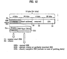
- FIG. 12 illustrates an SRR entry according to a fourth embodiment of the present invention.
- This fourth embodiment is identical to the third embodiment shown in FIG. 10 , except that the second part (3 bits) 31b of the Status field 31 of each SRR entry identifies the three different SRR types defined in FIG. 8 , instead of the eight different SRR types defined in FIG. 10 . That is, the Status field 31 includes the 1-bit S-flag and the 3-bits SRR type information, where the SRR type information is represented as one of "000b", "010b" and "100b".
- FIG. 16 illustrates a method of updating the SRR information according to the present invention. It involves sorting SRR entries included in the
- FIG. 16 can be applied to all the first to fifth embodiments of the present invention.
Abstract
Description
- The present invention relates to a write-once optical disc and a method and apparatus for recording management information on the write-once optical disc.
- As an optical recording medium, optical discs on which high-capacity data can be recorded are widely being used. Among them, a new high-density optical recording medium (HD-DVD), for example, a Blu-ray disc, has been recently developed for recording and storing high-definition video data and high-quality audio data for a long term period. The Blu-ray disc is the next generation HD-DVD technology and the next generation optical recording solution, and has an excellent capability to store data more than the existing DVDs. Recently, a technical specification of international standard for HD-DVD has been established.
- Related with this, various standards for a write-once Blu-ray disc (BD-WO) are being prepared following the standards for a rewritable Blu-ray disc (BD-RE).
- Among the standards for the write-once Blu-ray disc (BD-WO), a disc management information recording method is particularly discussed. This method includes a method of recording information on the recording status of the disc as a characteristic of the write-once optical disc. The information on the recording status of a disc is referred to herein as recording status information or disc recording status information.
- The recording status information represents a usage status of the disc, and allows a host or user to find easily a recordable area on the write-once optical disc. For the conventional write-once optical discs such as CDs and DVDs, the information on the disc recording status is known as: track information for the CD, and RZone or fragment for the DVD.
-
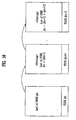
FIG. 1 is a schematic diagram illustrating the recording status information of a DVD-R disc according to a related art. - Referring to
FIG. 1 , the management information of the DVD-R is recorded in a recording management data (RMD) area. Particularly, the recording status information of the DVD-R is managed using RMD fields 4 - 12 of the RMD area. There are an open RZone, an invisible RZone and a closed RZone. - As for the RZone information, when a host requires an additionally recordable location to additionally record data on the disc, a driver confirms the LRAs (last recorded areas) of a first open RZone and a second open RZone, and generally transmits the location "LRA+1" as the additionally recordable location to the host.
- However, since the conventional DVD-R as described above is different from a write-once Blu-ray disc (BD-WO) in their physical structure and environment, the conventional method of providing management information cannot be just applied to the BD-WO. In case of the BD-WO, a driver manages disc defects, but the BD-WO is required to have a special additional area for the driver to manage the defects. The BD-WO, thus, has a complex disc structure and as a result, the method of managing the recording status of the DVD-R cannot be used for the BD-WO.
EP-A-1 623 422 authored by the Applicant represents a document falling under Article 54(3) of the EPC and describes a recording medium which comprises a track information list that includes one entry for each track in the corresponding data area of the disc. This track information entry includes track status information, a first address of the corresponding track and the last recorded address information of the track. - Accordingly, there is a need for a method of managing the recording status of a high density write-once optical disc such as a BD-WO, so that the disc can be accessed easily and used more effectively. And such management information should be structured to ensure compatibility with the overall structure, use and standards of the BD-WO.
- Accordingly, the present invention is directed to a write-once optical disc, and a method and apparatus for recording management information on the write-once optical disc, which substantially obviate one or more problems due to limitations and disadvantages of the related art.
- An object of the present invention is to provide a write-once optical disc such as a BD-WO with recording status information provided thereon, and a method and apparatus for efficiently recording and managing this recording status information.
- Another object of the present invention is to provide a technique of defining new sequential recording range (SRR) types for a write-once optical disc and recording the new SRR types in SRR information (SRRI).
- Additional advantages, objects, and features of the invention will be set forth in part in the description which follows and in part will become apparent to those having ordinary skill in the art upon examination of the following or may be learned from practice of the invention. The objectives and other advantages of the invention may be realized and attained by the structure particularly pointed out in the written description and claims hereof as well as the appended drawings
- To achieve these objects and other advantages and in accordance with the purpose of the invention, as embodied and broadly described herein, there is provided a recording medium as defined according to
claim 1, a method for recording management information as defined according toclaim 14 and an apparatus for recording management information as defined according to claim 26. It is to be understood that both the foregoing general description and the following detailed description of the present invention are exemplary and explanatory and are intended to provide further explanation of the invention as claimed. - The accompanying drawings, which are included to provide a further understanding of the invention and are incorporated in and constitute a part of this application, illustrate embodiment(s) of the invention and together with the description serve to explain the principle of the invention. In the drawings:
-
FIG. 1 is a schematic diagram illustrating management information recorded on a DVD-R disc according to the related art; -
FIGs. 2A to 2D illustrate different opened SRR types of a write-once optical disc according to the present invention; -
FIGs. 3A to 3E illustrate different closed SRR types of a write-once optical disc according to the present invention; -
FIGs. 4A to 4G illustrate an example of a process of recording SRR(s) and session(s) of a write-once optical disc according to the present invention; -
FIG. 5 illustrates a structure of a write-once optical disc and a method for recording disc management information on the write-once optical disc according to the present invention; -
FIG. 6 illustrates an SRR entry recordable on a write-once optical disc according to a first embodiment of the present invention; -
FIGs. 7A and7B illustrate an application of the SRR entry structure ofFIG. 6 to the cases ofFIGs. 4F and4G , respectively; -
FIG. 8 illustrates an SRR entry recordable on a write-once optical disc according to a second embodiment of the present invention; -
FIGs. 9A and9B illustrate an application of the SRR entry structure ofFIG. 8 to the cases ofFIGs. 4F and4G , respectively; -
FIG. 10 illustrates an SRR entry recordable on a write-once optical disc according to a third embodiment of the present invention; -
FIGs. 11A and11B illustrate an application of the SRR entry structure ofFIG. 10 to the cases ofFIGs. 4F and4G , respectively; -
FIG. 12 illustrates an SRR entry recordable on a write-once optical disc according to a fourth embodiment of the present invention; -
FIGs. 13A and13B illustrate an application of the SRR entry structure ofFIG. 12 to the cases ofFIGs. 4F and4G , respectively; -
FIG. 14 illustrates an SRR entry recordable on a write-once optical disc according to a fifth embodiment of the present invention; -
FIGs. 15A and15B illustrate an application of the SRR entry structure ofFIG. 14 to the cases ofFIGs. 4F and4G , respectively; -
FIG. 16 illustrates a method of updating SRR information on a write-once optical disc according to the present invention; and -
FIG. 17 illustrates an optical disc recording/reproducing apparatus according to the present invention. - Reference will now be made in detail to the preferred embodiments of the present invention, examples of which are illustrated in the accompanying drawings. Wherever possible, the same reference numbers are used throughout the drawings to refer to the same or like parts. For the convenience of description, a write-once Blu-ray disc (BD-WO) will be described as an example.
- In this specification, the terminology of the present invention employs generally popularized terms if possible. However, in a specific case, terms are arbitrarily selected by the inventor(s). In this case, since the meanings of the terms are defined in detail in the corresponding descriptions, it is understood that the invention should be understood with the defined meanings of the terms, if defined in the specification.
- According to the present invention, a plurality of areas are formed or reserved in a write-once optical disc so that these areas can be recorded with detailed information. Each of these special recording areas is called a sequential recording range (SRR). Information on the recording status (recording status information or disc recording status information) of a write-once optical disc such as a BD-WO is called an SRR information (SRRI), similar to the use of the term "sequence recording" in the sequence recording mode of a BD. "Padding" means recording dummy data, zero values, or some other designated padding data to an unrecorded or empty area in a closed SRR in response to the request of a user or according to the determination of a recording/reproducing unit (e.g.,
unit 10 shown inFIG. 17 ). "Session" is a common name used to divide the SRRs for compatibility according to the specification for reproduction. One session includes at least one SRR. - The present invention defines different types of SRRs to indicate exactly the recording status of each SRR in a write-once optical disc such as a BD-WO, and provides a structure for the write-once optical disc that would allow recording of such status information on the disc, with a full compatibility to the existing structure and use of the disc.
- An SRR is an area reserved for recording data or information on a write-once optical disc such as a BD-WO. The present invention defines the types of the SRRs according to necessity and/or a recording progress. The detailed description of various SRR types and session types that are defined by the present invention, is provided as follows referring to
FIGs. 2A-4G . -
FIGs. 2A to 2D illustrate different opened SRR types of SRRs for a write-once optical disc such as a BD-WO according to the present invention. An opened SRR means an SRR in which its area is recordable. "Recordable" means having a next writable address (NWA). Accordingly, the opened SRR is an SRR with an NWA. An unrecordable SRR without NWA is a closed SRR. The closed SRR types will be described later referring toFIGs. 3A to 3E . - More specifically,
FIG. 2A illustrates a first opened SRR, which is defined by the present inventors as an invisible SRR. The invisible SRR is an SRR formed in an outmost track area of a blank disc or a disc, which has not been recorded. Such an SRR has only a start address and no end address (i.e., no end to its area). Since the invisible SRR has no recording, its LRA has a zero value and its NWA has the same value as the start address of the invisible SRR. -
FIG. 2B illustrates a second opened SRR, which is defined by the present inventors as an incomplete SRR. The incomplete SRR is an SRR that is partially recorded from the invisible SRR state shown inFIG. 2A . In other words, an invisible SRR having some incomplete recording is referred to as an incomplete SRR. The incomplete SRR has a start address but no end address. As the SRR is incompletely recorded, its LRA is the address of the last location where the normal data is recorded and its NWA is information corresponding to a location next to the LRA. -
FIG. 2C illustrates a third opened SRR, which is defined by the present inventors as an empty SRR. The empty SRR is an SRR that is formed generally at a middle area of a disc, other than the outermost track of the disc. The empty SRR results when a host or user forms an opened SRR to record but has not recorded any data to the opened SRR. The empty SRR has a start address and an end address, but has not been recorded yet. As a result, the LRA of the empty SRR has a zero value and the NWA has the same value as the start address of the empty SRR. -
FIG. 2D illustrates a fourth opened SRR, which is defined by the present inventors as a partially recorded SRR. The partially recorded SRR is created when an empty SRR as inFIG. 2C is partially recorded with data. Accordingly, such an SRR has a start address and an end address. Since the SRR is partially recorded, the LRA of the partially recorded SRR is the last location where the normal data is recorded and the NWA of the partially recorded SRR is information corresponding to a location next to the LRA. - Generally, a conventional write-once disc such as a DVD-R has only two opened Rzones. In contrast, a write-once optical disc such as BD-WO according to the present invention does not have such a small limited number of opened SRRs. Instead, the total number of opened SRRs in the BD-WO is either unlimited or is limited to sixteen, so that the disc can be used more efficiently. Accordingly, the present invention also provides a method of recording management information that is different from the conventional recording methods.
-
FIGs. 3A to 3E illustrate different closed SRR types of a write-once optical disc such as a BD-WO according to the present invention. The closed SRR means an SRR having an unrecordable area. Being "unrecordable" means having no next writable address (NWA). The closed SRR can be reserved since its area is closed to recording. An SRR can be closed forcedly due to a close command from a host or user even though a recordable area remains in the SRR. -
FIG. 3A illustrates a first closed SRR, which is defined by the present inventors as an empty SRR. The empty SRR is an SRR that is closed without any recording due to a close command received in the opened empty SRR state shown inFIG. 2C . -
FIG. 3B illustrates a second closed SRR, which is defined by the present inventors as a partially recorded SRR. The partially recorded SRR is an SRR that is closed due to a close command received in the opened partially recorded SRR state shown inFIG. 2D . -
FIG. 3C illustrates a third closed SRR, which is defined by the present inventors as a complete SRR. The complete SRR is an SRR that is recorded fully with normal user data to the end of its area. A complete SRR exists only when the SRR is closed. -
FIG. 3D illustrates a fourth closed SRR, which is defined by the present inventors as another kind of a complete SRR. This complete SRR results when all the recordable (not yet recorded) area of the opened partially recorded SRR shown inFIG. 2D is padded with specific dummy data or zero values and then closed. -
FIG. 3E illustrates a fifth closed SRR, which is defined by the present inventors as another kind of a complete SRR. This complete SRR results when all the recordable (not yet recorded) area of the opened empty SRR shown inFIG. 2C is padded with specific dummy data or zero values and then closed. - As can be seen from
FIGs. 3A-3E , in the present invention, the type of an SRR is determined according to whether the unrecorded area is closed without any padding (FIGs. 3A and 3B ) or after padding (FIGs. 3D and 3E ) when the opened SRR is changed into a closed SRR. - Generally, there are three types of sessions according to the present invention. The first session type is an empty session made up of invisible SRRs. The second session type is an incomplete session that has at least one opened SRR, but no invisible SRR. The third session type is a complete session made up of closed SRRs. A session has at least one SRR. An incomplete session is changed into a complete session, e.g., due to a session close command.
-
FIGs. 4A to 4G illustrate, as an example, the steps of a method of reserving or assigning SRRs and sessions in a disc such as a BD-WO according to the present invention. An arrow indicates an NWA. - Particularly, referring to
FIG. 4A , in the first step, a blank write-once optical disc such as a BD-WO is provided with its entire area being recordable. In the state shown, the disc has only one SRR, which is an invisible SRR as shown inFIG. 2A , and the NWA of the disc is the start address of the disc. Accordingly, the disc has only on session, so-called, an empty session. - Referring to
FIG. 4B , in the second step, the blank disc is partially recorded but its session is not closed. In this state, the disc has only one SRR and this SRR is an incomplete SRR as shown inFIG. 2B . Accordingly, the disc has only one session, so-called, an incomplete session. - Referring to
FIG. 4C , in the third step, the previous session of the disc is closed due to a close command and becomes acomplete session # 1 having thecomplete SRR # 1. Then a new session is reserved as an empty session, where its unrecorded area is an invisible SRR as shownFIG. 2A . - Referring to
FIG. 4D , in the fourth step, two opened SRRs are reserved for new recordings. Accordingly, in addition to thecomplete session # 1, the disc has two new opened empty SRRs and the previous empty session is changed into an incomplete session. - Referring to
FIG. 4E , in the fifth step, data are recorded onto the first opened empty SRR ofFIG. 4D and onto the invisible SRR ofFIG. 4D . - Accordingly, the first empty SRR is changed into an opened partially recorded SRR and the invisible SRR is changed into an incomplete SRR. As a result, the disc still has the
complete session # 1 and the incomplete session. -
FIGs. 4F and4G show two possible steps each of which can follow the step ofFIG. 4E . InFIG. 4F , a session close command is received and processed to close the session without padding any unrecorded area. As a result, the recorded area in the incomplete session ofFIG. 4E becomes an independent newcomplete session # 2 due to the session close command, where all the SRRs in this session become closed SRRs. In other words, thecomplete session # 2 as reserved on the disc includes a closed partially recordedSRR # 2, a closedempty SRR # 3, and a closedcomplete SRR # 4. The remaining outmost SRR is an openedinvisible SRR # 5 and is part of anempty session # 3. - Alternatively, in
FIG. 4G , a session close command is received and processed to close the session without padding the unrecorded area(s). The recorded area then becomes an independentcomplete session # 2 due to the session close command, where all the SRRs in this session are changed into closed SRRs. In other words, as a result of performing the padding operation, the three kinds ofcomplete SRRs # 2, #3 and #4 are reserved on the disc as part of thecomplete session # 2. Thecomplete SRR # 2 is the opened partially recorded SRR ofFIG. 4E that is changed into a closed SRR after padding. Thecomplete SRR # 3 is the opened empty SRR ofFIG. 4E that is changed into a closed SRR after padding. Thecomplete SRR # 4 is a closed SRR having actual user data normally recorded therein. The remaining outmost SRR is an openedinvisible SRR # 5 which is part of anempty session # 3. - As can be seen from
FIGs. 4F and4G , a different kind of SRR can be reserved depending on whether or not there is padding. Accordingly, in order to represent the detail disc recording status of a disc, the present invention provides an innovative SRRI structure and a method of recording SRRI, so that these defined SRR types can be distinguished accurately. -
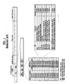
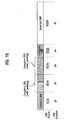
FIG. 5 illustrates a structure of a write-once optical disc such as a BD-WO and a method for recording disc management information according to the present invention. The disc shown inFIG. 5 has a single recording layer as an example. But the present invention is not limited to such, and is applicable to a disc having dual or multiple recording layers. - Referring to
FIG. 5 , the disc includes a lead-in area, a data area, and a lead-out area, all at the recording layer. The lead-in and lead-out areas have a plurality of defect management areas (DMA 1 - DMA4) for storing the same defect management information repeatedly. In the data area, an inner spare area ISAO and/or an outer spare area OSAO for replacing defective areas is provided. - It is known that a rewritable optical disc does not have or need a large defect management area (DMA) since its DMA can be written and erased repeatedly, even if the disc has the DMA of limited size. This is not the case for a write-once optical disc such as a BD-WO. Since the write-once optical disc cannot be re-recorded on the area that was recorded once, the write-once optical disc needs and has a larger I management area. To more effectively store management information, in the write-once optical disc the management information is temporarily stored in a temporary defect management area (TDMA).
- When the disc is ready to be finalized, then the management information stored in the TDMA is transferred to a DMA for more permanent storage.
- As shown in
FIG. 5 , there are two types of TDMA. One is a primary TDMA (PTDMAO) allocated to the lead-in area and having a fixed, non-variable size. The other is an additional TDMA (ATDMAO) allocated to the outer spare area OSAO and having a size variable in accordance with the size of the spare area. The size P of the ATDMAO is, for example, P = (N * 256) / 4 and is preferably a quarter of the size of the entire outer spare area OSAO. - In each of the PTDMAO and ATDMAO, temporary defect list (TDFL) information and temporary disc definition structure (TDDS) information are recorded in one record unit (e.g., one cluster in case of a BD-WO).
- In the alternative, in each of the PTDMAO and ATDMAO, (TDFL + TDDS) information or (SRRI and TDDS) information can be recorded in another record unit.
- The TDFL information is composed of 1 - 4 clusters according to the size of the defect area list. The SRR information identifies whether a specific area (SRR) of the disc is recorded or unrecorded. Especially, the SRR information can be applied when the disc is recorded in a consecutive recording method. The TDDS information is stored at the last sector of thirty-two sectors in one cluster. The TDDS information includes important information on the general disc management and the defect management. The TDDS information is generally always recorded at last whenever the management information is updated in the TDMA.
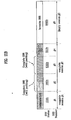
- According to the present invention, each of the plurality of
SRRIs 60 includes three parts: aheader 50 for causing the SRRI to be recognized, a list of SRR entries (SRR entry list) 30 including SRR type information, and anSRR list terminator 40 for identifying the termination of the corresponding SRRI. - The
SRRI header 50 is located at the front of the correspondingSRRI 60 and includes an "SRRI structure identifier"field 51 for causing the corresponding SRRI to be recognized, a "List of opened SRRs"field 52 for identifying the location of each opened SRR in the corresponding SRRI, a "Number of SRR entries"field 53 for identifying the total number of all SRRs, and a "Number of opened SRRs"field 54 for identifying the number of opened SRRs. By accessing theSRRI header 50, the general contents of theentire SRRI 60 can be known without having to access theSRR entry list 30 directly. Accordingly, it is possible to newly define any new SRR types or other necessary information and to insert this information into theheader 50. - The SRR entry list ("List of SRR entries") 30 is recorded after the
SRRI header 50. When theSRR entry list 30 is terminated, the termination of theSRR entry list 30 is identified with the SRR list terminator ("SRR List Terminator") 50. Specifically, theSRR list terminator 50 is information identifying the termination of the corresponding SRR information when the SRR information has a variable size. - Accordingly, as the disc management information, the SRR information includes the header, the SRR entry list and the SRR list terminator. Such information is recorded in the TDMA and updated as needed.
- The
SRR entry list 30 lists a plurality ofSRR entries 35. Eight bytes are allocated to eachSRR entry 35, and oneSRR entry 35 represents information on one SRR reserved on the disc. - Each
SRR entry 35 includes recording status information (SRR type information) (31) for the corresponding SRR, start address information (32) for the corresponding SRR, and last recorded address (LRA) information (34) for the corresponding SRR. The SRR type information identifies an SRR type of an SRR using the various SRR types defined by the present invention as discussed in connection withFIGs. 2A-3E . -
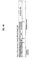
FIG. 6 illustrates an example of anSRR entry 35 according to a first embodiment of the present invention. As shown inFIG. 6 , eachSRR entry 35 includes a "Status"field 31 for storing 4-bit SRR type information, a "Start address"field 32, a "reserved"field 33 and an "LRA"field 34. - The appropriate SRR type information for the corresponding SRR is recorded in the
Status field 31, so that by accessing theStatus field 31, the recording status of the SRR can be known. Particularly, any one of the nine different SRR types discussed above in connection withFIGs. 2A - 3E can be represented in theStatus field 31. In this regard, the complete SRRs with padding shown inFIGs. 3D and 3E are grouped together as one type. - As an example, if the
Status field 31 has a value "0000b", it means the corresponding SRR is an opened invisible SRR, e.g., as shown inFIG. 2A . If theStatus field 31 has a value "0001b", it means the corresponding SRR is an opened incomplete SRR, e.g., as shown inFIG. 2B . If theStatus field 31 has a value "0010b", it means the corresponding SRR is an opened empty SRR, e.g., as shown inFIG. 2C . - If the
Status field 31 has a value "0011b", it means the corresponding SRR is an opened partially recorded SRR, e.g., as shown inFIG. 2D . If theStatus field 31 has a value "0100b", it means the corresponding SRR is a closed empty SRR, e.g., as shown inFIG. 3A . If theStatus field 31 has a value "0101b", it means the corresponding SRR is a closed partially recorded SRR, e.g., as shown inFIG. 3B . If theStatus field 31 has a value "0110b", it means the corresponding SRR is a closed complete SRR with an unrecorded area padded with dummy data, e.g., as shown inFIGs. 3D and 3E . If theStatus field 31 has a value "0111b", it means the corresponding SRR is a closed complete SRR without any padding, e.g., as shown inFIG. 3C . - The
Start address field 32 has the size of twenty-eight bits and is used to record the start address information of the corresponding SRR, that is, the address of the start location of the SRR. Generally, this is represented as a physical sector number (PSN). - The
Reserved field 33 has the size of four bits and is reserved for specification variations. - The
LRA field 34 has the size of twenty-eight bits and is used to record the last recorded address information (LRA) of the corresponding SRR. This field has information on the last location of user data (except for padding data) that is recorded in the SRR. -
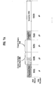
FIGs. 7A and7B illustrate respectively how the SRR type information as defined inFIG. 6 can be applied to indicate the recording status of each SRR shown inFIG. 4F (without padding) andFIG. 4G (with padding). - Referring to
FIG. 7A , theSRR # 1 is a complete SRR without padding and this status is indicated with "0111b" in theStatus field 31. TheSRR # 2 is a closed partially recorded SRR without padding and this status is indicated with "0101b" in theStatus field 31. TheSRR # 3 is a closed empty SRR without padding and this status is indicated with "0100b" in theStatus field 31. TheSRR # 4 is a complete SRR without padding and this status is indicated with "0111b" in theStatus field 31. TheSRR # 5 is an invisible SRR and this status is indicated with "0000b" in theStatus field 31. - On the other hand, referring to
FIG. 7B , theSRR # 1 is a complete SRR without padding and this status is indicated with "0111b" in theStatus field 31. TheSRR # 2 is a complete SRR with padding and this status is indicated with "0111b" in theStatus field 31. TheSRR # 3 is a complete SRR with padding and this status is indicated with "0110b" in theStatus field 31. TheSRR # 4 is a complete SRR without padding and this status is indicated with "0111b" in theStatus field 31. TheSRR # 5 is an invisible SRR and this status is indicated with "0000b" in theStatus field 31. - Accordingly, using the different SRR types defined as shown in
FIG. 6 and the Status field, the exact disc recording status can be known and managed more effectively. -
FIG. 8 illustrates an SRR entry according to a second embodiment of the present invention. In this embodiment, the SRR entries are classified into opened SRRs and closed SRRs. And the closed SRRs are classified according to whether or not padding is used. Since the basic structure of the SRR entry in this second embodiment is the same as the first embodiment ofFIG. 6 , the description corresponding to the same features of the SRR entry (as represented by the use of the same or like reference numerals) will be omitted. - Referring to
FIG. 8 , three different SRR types defined in this second embodiment are an opened SRR, a closed empty or partially recorded SRR, and a closed complete SRR. Thus one of these three different SRR types is indicated in theStatus field 31 of an SRR entry according to the recording status (SRR type) of the SRR entry. - For instance, if the
Status field 31 has a value "0000b," it means the corresponding SRR is an opened SRR and can be any one kind of opened SRRs shown inFIGs. 2A - 2D . If theStatus field 31 has a value "0010b," it means the corresponding SRR is a closed empty SRR with padding or a closed partially recorded SRR as shown inFIGs. 3A and 3B . If thestatus field 31 has a value "0100b," it means the corresponding SRR is a complete SRR including the case in which data is fully recorded as shownFIG. 3C or the case in which the recording is completed with padding as shown inFIG. 3D or 3E . - The reason why the SRR type information of the
Status field 31 in the second embodiment can be defined simpler that that in the first embodiment is as follows. The LRAs of the SRRs inFIGs. 3C, 3D and 3E are different from each other although the SRRs are all complete SRRs. Similarly, the opened SRRs ofFIGs. 2A-2D have different starting addresses and LRAs. Then using theStatus field 31 along with theLRA field 34 and thestart address field 32, the type of the SRR can be identified further. -
FIGs. 9A and9B illustrate respectively how the SRR type information as defined inFIG. 8 can be applied to indicate the recording status of each SRR shown inFIG. 4F (without padding) andFIG. 4G (with padding). - Referring to
FIG. 9A , theSRR # 1 is a complete SRR and this status is indicated with "0100b" in theStatus field 31. TheSRR # 2 is a closed partially recorded SRR without padding and this status is indicated with "0010b" in theStatus field 31. TheSRR # 3 is a closed empty SRR without padding and this status is indicated with "0010b" in theStatus field 31. TheSRR # 4 is a complete SRR and this status is indicated with "0100b" in theStatus field 31. TheSRR # 5 means an invisible SRR and this status is indicated with "0000b" in theStatus field 31. - On the other hand, referring to
FIG. 9B , theSRR # 1 is a complete SRR and this status is indicated with "0100b" in theStatus field 31. TheSRR # 2 is a complete SRR with padding and this status is indicated with "0100b" in theStatus field 31. TheSRR # 3 is a complete SRR with padding and this status is indicated with "0100b" in theStatus field 31. TheSRR # 4 is a complete SRR and this status is indicated with "0100b" in theStatus field 31. TheSRR # 5 is an invisible SRR and this status is indicated with "0000b" in theStatus field 31. -
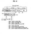
FIG. 10 illustrates an SRR entry according to a third embodiment of the present invention. Similar to the first embodiment ofFIG. 6 , this embodiment provides the SRR type information in theStatus field 31. But it further provides session information in theStatus field 31. Since the basic structure of the SRR entry in this third embodiment is the same as the first embodiment ofFIG. 6 , the description corresponding to the same features of the SRR entry (as represented by the use of the same or like reference numerals) will be omitted. - Referring to
FIG. 10 , theStatus field 31 is divided into twoparts first part 31a has a 1 bit size and stores therein session flag (S-flag) information. The S-flag information indicates whether or not the corresponding SRR is the start of a session. Thesecond part 31b or the three remaining bits of theStatus field 31 store thereinSRR Type information 31 b identifying the SRR types in the same manner as the first embodiment as shown inFIG. 6 . - More specifically, if one heading bit (S-flag) 31a of the
Status field 31 is "1b", it means the corresponding SRR is the start SRR of a session. If thefirst part 31a has a value "0b", then the corresponding SRR is not the start SRR of a session. - If the
second part 31 b (the three remaining bits) of theStatus field 31 has a value "000b," it means the corresponding SRR is an opened invisible SRR, e.g., as shown inFIG. 2A . If thesecond part 31b has a value "001b," it means the corresponding SRR is an opened incomplete SRR, e.g., as shown inFIG. 2B . If thesecond part 31b has a value "010b," it means the corresponding SRR is an opened empty SRR, e.g., as shown inFIG. 2C . If thesecond part 31b has a value "011b," it means the corresponding SRR is an opened partially recorded SRR, e.g., as shown inFIG. 2D . If thesecond part 31b has a value "100b," it means the corresponding SRR is a closed empty SRR, e.g., as shown inFIG. 3A . If thesecond part 31b has a value "101b," it means the corresponding SRR is a closed partially recorded SRR, e.g., as shown inFIG. 3B . If thesecond part 31b has a value "110b," it means the corresponding SRR is a closed complete SRR with padding, e.g., as shown inFIGs. 3D and 3E . If thesecond part 31b has a value "111b," it means the corresponding SRR is a closed complete SRR without padding, e.g., as shown inFIG. 3C . -
FIGs. 11A and11B illustrate respectively how the SRR type information and session information as defined inFIG. 10 can be applied to indicate the recording status of each SRR and session shown inFIG. 4F (without padding) andFIG. 4G (with padding). - Referring to
FIG. 11A , since theSRR # 1 is a complete SRR without padding and also is the start SRR of thesession # 1, this status is indicated with "1111b" in theStatus field 32. That is, this four-bit Status field 31 includes the one-bit session flag (31a) and the remaining three-bits SRR type information (31b) as discussed above. Since theSRR # 2 is a closed partially recorded SRR without padding and also is the start SRR of thesession # 2, this status is indicated with "1101b" in theStatus field 31. Since theSRR # 3 is a closed empty SRR without padding but is not the start SRR of thesession # 2, this status is indicated with "0100b" in theStatus field 31. Since theSRR # 4 is a complete SRR without padding but is not the start SRR of thesession # 2, this status is indicated with "0111b" in theStatus field 31. Since theSRR # 5 is an invisible SRR and also is the start SRR of thesession # 3, this status is indicated with "1000b" in theStatus field 31. - On the other hand, referring to
FIG. 11B , since theSRR # 1 is a complete SRR without padding and also is the start SRR of thesession # 1, this status is indicated with "1111b" in theStatus field 31. Since theSRR # 2 is a complete SRR with padding and also is the start SRR of thesession # 2, this status is indicated with "1110b" in theStatus field 31. Since theSRR # 3 is a complete SRR with padding but is not the start SRR of thesession # 2, this status is indicated with "0110b" in theStatus field 31. Since theSRR # 4 is a complete SRR without padding but is not the start SRR of thesession # 2, this status is indicated with "0111b" in theStatus field 31. Since theSRR # 5 is an invisible SRR and also is the start SRR of thesession # 3, this status is indicated with "1000b" in theStatus field 31. - Accordingly, since both the session start information and the SRR type information are provided in the Status field of each SRR entry, the type of each SRR and the start location of each session can be known and used to more effectively manage and utilize the disc.
-
FIG. 12 illustrates an SRR entry according to a fourth embodiment of the present invention. This fourth embodiment is identical to the third embodiment shown inFIG. 10 , except that the second part (3 bits) 31b of theStatus field 31 of each SRR entry identifies the three different SRR types defined inFIG. 8 , instead of the eight different SRR types defined inFIG. 10 . That is, theStatus field 31 includes the 1-bit S-flag and the 3-bits SRR type information, where the SRR type information is represented as one of "000b", "010b" and "100b". -
FIGs. 13A and13B illustrate respectively how the SRR type information and session information as defined inFIG. 12 can be applied to indicate the recording status of each. SRR and session shown inFIG. 4F (without padding) andFIG. 4G (with padding). - Referring to
FIG. 13A , since theSRR # 1 is a complete SRR and also is the start SRR of thesession # 1, this status is indicated with "1100b" in theStart field 31. Since theSRR # 2 is a closed partially recorded SRR without padding and also is the start SRR of thesession # 2, this status is indicated with "1010b" in theStatus field 31. Since theSRR # 3 is a closed empty SRR without padding but is not the start SRR of thesession # 2, this status is indicated with "0010b" in theStatus field 31. - Since the
SRR # 4 is a complete SRR but is not the start SRR of thesession # 2, this status is indicated with "0100b" in theStatus field 31. - Since the
SRR # 5 is an opened invisible SRR and also is the start SRR of thesession # 3, this status is indicated with "1000b" in theStatus field 31. - On the other hand, referring to
FIG. 13B , since theSRR # 1 is a complete SRR and also is the start SRR of thesession # 1, this status is indicated with "1100b" in theStatus field 31. Since theSRR # 2 is a complete SRR with padding and also is the start SRR of thesession # 2, this status is indicated with "1100b" in theStatus field 31. Since theSRR # 3 is a complete SRR with padding but is not the start SRR of thesession # 2, this status is indicated with "0100b" in theStatus field 31. - Since the
SRR # 4 is a complete SRR but is not the start SRR of thesession # 2, this status is indicated with "0100b" in theStatus field 31. - Since the
SRR # 5 is an opened invisible SRR and also is the start SRR of thesession # 3, this status is indicated with "1000b" in theStatus field 31. -
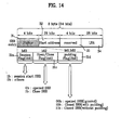
FIG. 14 illustrates an SRR entry according to a fifth embodiment of the present invention. Sessions, opened/closed SRR and padding of the closed SRR can be identified with separately allocated bit(s). Referring toFIG. 14 , theStatus field 31 of each SRR entry is divided into thefirst part 31a (S-flag), asecond part 31c being an open/close flag, and athird part 31d being a padding flag. - The first heading bit b63 (31a) of the
Status field 31 is designated to carry the S-flag information indicating whether the corresponding SRR is the start of a session. The use and definition of the S-flag information here is the same as the S-flag information (31a) in the previous embodiments. One next bit b62 (31c) is designated as the open/close flag indicating whether the corresponding SRR is an opened SRR or a closed SRR. The two remaining bits b61 and b60 (31d) of theStatus field 31 are designated as a padding flag indicating whether or not the closed SRR is padded. - As an example, if the open/close flag (31c) has a value "0b", it means the corresponding SRR is an opened SRR. If the open/close flag (31c) has a value "1b", it means the corresponding SRR is a closed SRR.
- As an example, if the two remaining bits (31d) of the Status field 31 (i.e., the padding flag) are "00b", it means the corresponding SRR is an opened SRR regardless of whether it is padded or not. If the padding flag has a value "10b", it means the corresponding SRR is a closed SRR with padding. If the padding flag has a value "11b", it means the corresponding SRR is a closed SRR without padding.
-
FIGs. 15A and15B illustrate respectively how the SRR type information and session information as defined inFIG. 14 can be applied to indicate the recording status of each SRR and session shown inFIG. 4F (without padding) andFIG. 4G (with padding). - Referring to
FIG. 15A , since theSRR # 1 is a complete SRR without padding and also is the start SRR of thesession # 1, this status is indicated with "1111b" in theStatus field 31. Since theSRR # 2 is a closed partially recorded SRR without padding and also is the start SRR of thesession # 2, this status is indicated with "1111b" in theStatus field 31. SinceSRR # 3 is a closed empty SRR without padding but is not the start SRR of thesession # 2, this status is indicated with "0111b" in theStatus field 31. Since theSRR # 4 is a complete SRR without padding but is not the start SRR of thesession # 2, this status is indicated with "0111b" in theStatus field 31. Since theSRR # 5 is an opened invisible SRR and also is the start SRR of thesession # 3, this status is indicated with "1000b" in theStatus field 31. - On the other hand, referring to
FIG. 15B , since theSRR # 1 is a complete SRR without padding and also is the start SRR of thesession # 1, this status is indicated with "1111b" in theStart field 31. Since theSRR # 2 is a complete SRR with padding and also is the start SRR of thesession # 2, this status is indicated with "1110b" in theStart field 31. - Since the
SRR # 3 is a complete SRR with padding but is not the start SRR of thesession # 2, this status is indicated with "0110b" in theStatus field 31. Since theSRR # 4 is a complete SRR without padding but is not the start SRR of thesession # 2, this status is indicated with "0111b" in theStatus field 31. Since theSRR # 5 is an opened invisible SRR and also is the start SRR of thesession # 3, this status is indicated with "1000b" in theStatus field 31. - Since in the fifth embodiment the session start information, the opened/closed SRR indicating information and the padding information can be indicated separately using the different flags or bits of the
- Status field, such information can be identified and managed more precisely and effectively.
- In the various embodiments of the present invention, the size of each field or each flag of the field can be varied according to the need. For instance, instead of having a 1-bit session flag (31a), it is possible to use two-bits session flag. Further, the manner in which the different values of the flags/fields are assigned to indicate different information (e.g., different SRR types, session start information, open/close information or padding information) can be selectively changed as needed. For instance, in
FIG. 14 , the padding flag values of "00b", "10b" and "11b" can be designated to indicate respectively a closed SRR without padding, a closed SRR with padding, and an opened SRR. - Moreover the location of each flag within the Start field, or the location of each field in the SRR entry may be changed. For instance, the session flag can be any one of the first four bits of the Status field.
-
FIG. 16 illustrates a method of updating the SRR information according to the present invention. It involves sorting SRR entries included in the - SRRI in a specific order and recording the sorted SRRI accumulatively.
- The method of
FIG. 16 can be applied to all the first to fifth embodiments of the present invention. - Referring to
FIG. 16 , the n-th recorded SRR information is verified to record the (n+1)-th updated SRR information. The n-th recorded SRR information and the (n+1)-th SRR information to be updated currently are collected together and sorted in a specific order. Then the sorted SRRI is recorded on the disc. In the same manner, the (n+1)-th recorded SRR information is verified to record the (n+2)-th updated SRR information. The (n+1)-th recorded SRR information and the (n+2)-th SRR information to be updated currently are collected together and sorted in a specific order. The sorted SRRI information is recorded on the disc. - As an example, as for the sorting order, the SRR type information (status) identifying the SRR type of an SRR entry is the first criteria by which the sorting occurs. Then among the same SRR types, the start address of the SRRs is used as the second criteria to sort. However, as for the sorting order, how to determine the sorting criterion is a selection problem and various selections can be made according to a system or a designer.
- According to the present invention, all the SRRs existing in the write-once optical disc such as a BD-WO can be sorted according to the SRR type so that the SRR type information for the SRRs can be easily recognized. All the previous SRRI can be confirmed at once only with reference to the latest SRRI updated last, so that the access time can be saved.
-
FIG. 17 illustrates an optical disc recording/reproducing apparatus according to the present invention. This apparatus or other suitable apparatus or system can be used to implement the structure of the disc and the method of recording the disc management information including the recording status information, as discussed in the various embodiments of the present invention. - Referring to
FIG. 17 , the optical disc recording/reproducing apparatus includes a recording/ reproducingunit 10 for recording and reproducing data to/from the optical disc and acontroller 20 for controlling the recording/reproducingunit 10. All the elements of the recording/reproducing apparatus are operatively coupled. Thecontroller 20 transmits a command for recording or reproducing to/from a special recording area such as an SRR/session on the disc, to the recording/reproducingunit 10. The recording/reproducingunit 10 records or reproduces data to/from the disc according to the commands of thecontroller 20. The recording/reproducingunit 10 includes aninterface unit 12, a pick-upunit 11, adata processor 13, aservo unit 14, amemory 15 and amicrocomputer 16. Theinterface unit 12 communicates with external devices such as thecontroller 20. - The pick-up
unit 11 records or reproduces data to/from the optical disc directly. Thedata processor 13 receives a reproduction signal from the pick-upunit 11, restores a preferred signal, modulates a signal proper to the optical disc, and transmits the signal. Theservo unit 14 controls the pick-upunit 11 to read the signal from the optical disc or to record the signal to the optical disc. Thememory 15 stores temporarily data and various information including management information as discussed above. Themicrocomputer 16 controls the components of the recording/reproducingunit 10. Since the recording/reproducing apparatus shown inFIG. 17 can selectively perform a padding operation, a designer can more freely design the recording/reproducing apparatus. The recording/reproducingunit 10 can automatically store specific data during a padding operation. - An optical disc recording/reproducing process will be described according to the present invention. When the optical disc such as a BD-WO is loaded in the recording/reproducing apparatus such as the apparatus of
FIG. 17 , SRR information is read as the recent disc management information recorded in a predetermined management area such as a TDMA in the disc. The SRR header and SRR entry recorded in the SRR information are read and are temporarily recorded in thememory 15 of the recording/reproducingunit 10. The recent disc recording status is represented in the stored SRR information. As discussed above, the disc recording status for the entire area of the disc, and the existence and location of a specific session can be confirmed from the SRR type information and the LRA information in each SRR. - As a result, the use of the SRRI as defined according to the present invention is advantageous and effective.
- For instance, since the
microcomputer 16 can confirm exactly the SRR type existing in the disc from the SRR information, the recordable NWA can be identified from the confirmed opened SRR. From the confirmed closed SRR, it can be confirmed whether or not the SRR is padded. If the SRR is closed without padding, the corresponding area may be padded, so that the unrecorded area can be cleared. - When the SRR is closed according to the close command of the
controller 20, themicrocomputer 16 can determine whether the SRR is closed after padding or without padding. According to the designer, the apparatus can be designed to close the SRR after padding unconditionally even without any padding command from thecontroller 20. - When the SRR type is changed due to padding as described above, the SRR type information in the SRR entry is changed and recorded, so that another recording/reproducing apparatus can use such information.
- The function described above can be called "automatic padding function" of the recording/reproducing
unit 10. The use of this function in the recording/reproducingunit 10 may be more advantageous in time over receiving the dummy data in response to a padding command of thecontroller 20 and padding the SRR. - Accordingly, the definitions of the SRR type and the method of recording the SRR information according to the set definitions can be variably selected.
- The write-once optical disc management information recording method according to the present invention includes defining new SRR types and session types representing disc recording status more precisely, and recording identification information for identifying an SRR type and a session in the SRR information, so that the management information can be efficiently recorded and managed.
- It will be apparent to those skilled in the art that various modifications and variations can be made in the present invention. Thus, it is intended that the present invention covers the modifications and variations of this invention provided they come within the scope of the appended claims and their equivalents.
Claims (31)
- A recording medium comprising:at least one recording layer having one or more sequential recording ranges (SRR) formed for storing data; andone or more sequential recording range entries, each sequential recording range entry corresponding to a sequential recording range and including at least one status field (31) for indicating a recording status of the corresponding sequential recording range, the at least one status field including a session start flag (31a) for indicating whether the corresponding sequential recording range is a start of a session, the session being a group of at least one sequential recording range, each sequential recording range entry further including a start address field (32) indicating where the corresponding sequential recording range starts, and a last address field (34) indicating the last recorded address of the corresponding sequential recording range;whereinthe recording medium comprises a list of opened sequential recording ranges (52) for identifying each opened sequential recording range which has a recordable location.
- The recording medium of claim 1, wherein the each sequential recording range entry consists of a 64-bit sequence with most significant bit being the first bit in the 64-bit sequence.
- The recording medium of claim 1 or 2, wherein the at least one status field has a size of 4 bits, one of 4 bits being used as the session start flag.
- The recording medium of one of claims 1 to 3, wherein each of the start address field and the last address field has a size of 28 bits.
- The recording medium of one of claims 1 to 4, wherein the at least one status field further includes:an sequential recording range type field for indicating a type of the corresponding sequential recording range.
- The recording medium of claim 5, wherein the sequential recording range type field has a size of 3 bits.
- The recording medium of claim 5 or 6, wherein the sequential recording range type field indicates whether the corresponding sequential recording range is an opened sequential recording range or a closed sequential recording range which has no recordable location.
- The recording medium of claim 5, wherein the sequential recording range type field indicates that the corresponding sequential recording range is one of the following:an opened, invisible sequential recording range which has not been recorded, has a recordable location, and has a start address but no end address;an opened, incomplete sequential recording range which is partially recorded, has a recordable location, and has a start address but no end address;an opened, empty sequential recording range which has not been recorded, has a recordable location, and has a start address and an end address;an opened, partially recorded sequential recording range which is partially recorded, has a recordable location, and has a start address and an end address;a closed, empty sequential recording range which has not been recorded, has no recordable location, and has a start address and an end address;a closed, partially recorded sequential recording range which is partially recorded, has no recordable location, and has a start address and an end address;a closed, complete sequential recording range with padded data which is fully or partially padded with dummy data and has no recordable location; anda closed, complete sequential recording range without padded data which is fully recorded with user data and has no recordable location.
- The recording medium of claim 5, wherein the sequential recording range type field indicates that the corresponding sequential recording range is one of the following:an opened sequential recording range;an opened empty sequential recording range or an opened, partially recorded sequential recording range; anda closed, complete sequential recording range.
- The recording medium of one of claims 1 to 7, wherein the at least one status field further includes:an open/close flag for indicating whether the corresponding sequential recording range is an opened sequential recording range or a closed sequential recording range.
- The recording medium of one of claims 1 to 10, wherein the sequential recording range entries form a sequential recording range entry list, the sequential recording range entries being sorted in a predetermined order based on the start address field.
- The recording medium of claim 5, wherein the sequential recording range entries form a sequential recording range entry list, the sequential recording range entries being sorted in a predetermined order based on the sequential recording range type field.
- The recording medium of one of claims 1 to 12, wherein the sequential recording range entries are stored in a temporary defect management area designated on the at least one recording layer.
- A method for recording management information on a recording medium having at least one recording layer having one or more sequential recording ranges (SRR) formed for storing data, the method comprising a step of:(a) recording one or more sequential recording range entries on the at least one recording layer, each sequential recording range entry corresponding to a sequential recording range and including at least one status field (31) for indicating a recording status of the corresponding sequential recording range, the at least one status field (31) including a session start flag (31a) for indicating whether the corresponding sequential recording range is a start of a session, the session being formed by a group of at least one sequential recording range, each sequential recording range entry further including a start address field (32) indicating where the corresponding sequential recording range starts, and a last address field (34) indicating the last recorded address of the corresponding sequential recording range;whereinthe method comprises a step of (b) recording a list of opened sequential recording ranges (52) for identifying each opened sequential recording-range which has recordable location.
- The method of claim 14, wherein the recording step (a) records the each sequential recording range entry consisting of a 64-bit sequence with most significant bit being the first bit in the 64-bit sequence.
- The method of claim 14 or 15, wherein the recording step (a) records the at least one status field including an sequential recording range status field having a size of 4 bits, one of the 4 bits being used as the session start flag.
- The method of one of claims 14 to 16, wherein the recording step (a) records each of the start address field and the last address field with a size of 28 bits.
- The method of one of claims 14 to 17, wherein the recording step records the at least one status field which further includes a sequential recording range type field for indicating a type of the corresponding sequential recording range.
- The method of claim 18, wherein the sequential recording range type field indicates whether the corresponding sequential recording range is an opened sequential recording range or a closed sequential recording range which has no recordable location.
- The method of claim 18, wherein the sequential recording range type field indicate that the corresponding sequential recording range is one of the following:an opened, invisible sequential recording range which has not been recorded, has a recordable location, and has a start address but no end address;an opened, incomplete sequential recording range which is partially recorded, has a recordable location, and has a start address but no end address;an opened, empty sequential recording range which has not been recorded, has a recordable location, and has a start address and an end address;an opened, partially recorded sequential recording range which is partially recorded, has a recordable location, and has a start address and an end address;a closed; empty sequential recording range sequential recording range which has not been recorded, has no recordable location, and has a start address and an end address;a closed, partially recorded sequential recording range which is partially recorded, has no recordable location, and has a start address and an end address;a closed, complete sequential recording range with padded data which is fully or partially padded with dummy data and has no recordable location; anda closed, complete sequential recording range without padded data which is fully recorded with user data and has no recordable location.
- The method of claim 18, wherein the sequential recording range type field indicates that the corresponding sequential recording range is one of the following:an opened sequential recording range;an opened empty sequential recording range or an opened, partially recorded sequential recording range; anda closed, complete sequential recording range.
- The method of one of claims 14 to 21, wherein the recording step (a) records the at least one status field which further includes an open/close flag for indicating whether the corresponding sequential recording range is an opened sequential recording range or a closed sequential recording range.
- The method of one of claims 14 to 22, wherein the sequential recording range entries form a sequential recording range entry list, and the method further comprises:sorting the sequential recording range entries in a predetermined order based on the start address field.
- The method of claim 18, wherein the sequential recording range entries form an sequential recording range entry list, and the method further comprises:sorting the sequential recording range entries in a predetermined order based on the sequential recording range type field.
- The method of one of claims 14 to 24, wherein the recording step (a) and (b) record the sequential recording range entries and the list of opened sequential recording ranges in a temporary defect management area designated on the at least one recording layer.
- An apparatus for recording management information on a recording medium having at least one recording layer having one or more sequential recording ranges formed for storing data, the apparatus comprising:an optical pickup (11) configured to record data on the recording medium; anda microcomputer (16) configured to control the optical pickup (11) to record one or more sequential recording range entries on the at least one recording layer, each sequential recording range entry corresponding to a sequential recording range (SRR) and including at least one status field (31) for indicating a recording status of the corresponding sequential recording range, the at least one status field (31) including a session start flag (31a) for indicating whether the corresponding sequential recording range is a start of a session, the session being formed by a group of at least one sequential recording range, each sequential recording range entry further including a start address field (32) indicating where the corresponding sequential recording range starts, and a last address field (34) indicating the last recorded address of the corresponding sequential recording range;whereinthe microcomputer (16) is configured to control the pickup (11) to record a list of opened sequential recording ranges (52) for identifying each opened sequential recording range which has a recordable location.
- The apparatus of claim 26, wherein the microcomputer (16) is configured to control the pickup (11) to record each of the at least one status filed having a size of 4 bits, one of the 4 bits being used as the session start flag.
- The apparatus of claim 26 or 27, wherein the microcomputer (16) is configured to control the pickup (11) to record the at least one status field which further includes a sequential recording range type filed having a size of 3 bits for indicating a type of the corresponding sequential recording range.
- The apparatus of claim 28, wherein the microcomputer (16) is configured to control the pickup (11) to record the sequential recording range type field indicating that the corresponding sequential recording range one of the following:an opened sequential recording range;an opened empty sequential recording range or an opened, partially recorded sequential recording range; anda closed, complete sequential recording range.
- The apparatus of one of claims 26 to 29, wherein the microcomputer (16) is configured to control the pickup (11) to record the at least one status field which further includes an open/close flag for indicating whether the corresponding sequential recording range is an opened sequential recording range or a closed sequential recording range.
- The apparatus of one of claims 26 to 30, further comprising:a host (20) configured for transmitting to the microcomputer (16) a command for recording/reproducing the sequential recording range entries on/from the recording medium,wherein the microcomputer (16) is configured to control the pickup (11) according to the command from the host (20).
Priority Applications (1)
| Application Number | Priority Date | Filing Date | Title |
|---|---|---|---|
| EP09156887A EP2096641A3 (en) | 2003-07-14 | 2004-07-09 | Write-once optical disc, method and apparatus for recording management information on write-once optical disc |
Applications Claiming Priority (3)
| Application Number | Priority Date | Filing Date | Title |
|---|---|---|---|
| KR1020030047989A KR20050008141A (en) | 2003-07-14 | 2003-07-14 | Method for recording management information on optical disc write once |
| KR1020030062379A KR20050026757A (en) | 2003-09-06 | 2003-09-06 | Method for recording management information on optical disc write once |
| PCT/KR2004/001700 WO2005006314A1 (en) | 2003-07-14 | 2004-07-09 | Write-once optical disc, method and apparatus for recording management information on write-once optical disc |
Related Child Applications (1)
| Application Number | Title | Priority Date | Filing Date |
|---|---|---|---|
| EP09156887A Division EP2096641A3 (en) | 2003-07-14 | 2004-07-09 | Write-once optical disc, method and apparatus for recording management information on write-once optical disc |
Publications (2)
| Publication Number | Publication Date |
|---|---|
| EP1644920A1 EP1644920A1 (en) | 2006-04-12 |
| EP1644920B1 true EP1644920B1 (en) | 2009-05-06 |
Family
ID=36642319
Family Applications (2)
| Application Number | Title | Priority Date | Filing Date |
|---|---|---|---|
| EP09156887A Ceased EP2096641A3 (en) | 2003-07-14 | 2004-07-09 | Write-once optical disc, method and apparatus for recording management information on write-once optical disc |
| EP04748404A Active EP1644920B1 (en) | 2003-07-14 | 2004-07-09 | Write-once optical disc, method and apparatus for recording management information on write-once optical disc |
Family Applications Before (1)
| Application Number | Title | Priority Date | Filing Date |
|---|---|---|---|
| EP09156887A Ceased EP2096641A3 (en) | 2003-07-14 | 2004-07-09 | Write-once optical disc, method and apparatus for recording management information on write-once optical disc |
Country Status (14)
| Country | Link |
|---|---|
| US (2) | US7372792B2 (en) |
| EP (2) | EP2096641A3 (en) |
| JP (2) | JP4750027B2 (en) |
| KR (1) | KR101049135B1 (en) |
| AT (1) | ATE430976T1 (en) |
| AU (1) | AU2004256684B2 (en) |
| BR (1) | BRPI0412556A (en) |
| CA (1) | CA2532371C (en) |
| DE (1) | DE602004020992D1 (en) |
| ES (1) | ES2325441T3 (en) |
| MX (1) | MXPA06000588A (en) |
| RU (1) | RU2355047C2 (en) |
| TW (1) | TWI279780B (en) |
| WO (1) | WO2005006314A1 (en) |
Cited By (5)
| Publication number | Priority date | Publication date | Assignee | Title |
|---|---|---|---|---|
| US7783829B2 (en) | 2003-09-08 | 2010-08-24 | Lg Electronics Inc. | Write-once optical disc and method for recording management information thereon |
| US7813243B2 (en) | 2003-01-11 | 2010-10-12 | Lg Electronics Inc. | Optical disc of write once type, method, and apparatus for managing defect information on the optical disc |
| US7911900B2 (en) | 2003-09-08 | 2011-03-22 | Lg Electronics Inc. | Write-once optical disc, and method and apparatus for recording management information on the write-once optical disc |
| US7936649B2 (en) | 2002-12-11 | 2011-05-03 | Lg Electronics Inc. | Method of managing overwrite and method of recording management information on an optical disc write once |
| US8296529B2 (en) | 2003-09-08 | 2012-10-23 | Lg Electronics Inc. | Write-once optical disc and method for recording management information thereon |
Families Citing this family (44)
| Publication number | Priority date | Publication date | Assignee | Title |
|---|---|---|---|---|
| BRPI0306564B1 (en) * | 2002-09-26 | 2016-04-26 | Lg Electronics Inc | method of recording optical media management having at least one defective area in the user data area, recording media and recording optical media management apparatus having at least one temporary defect management area and a spare area in the data area |
| KR20040027259A (en) * | 2002-09-26 | 2004-04-01 | 엘지전자 주식회사 | Method for managing a defect area on optical disc write once |
| KR20040028469A (en) | 2002-09-30 | 2004-04-03 | 엘지전자 주식회사 | Method for managing a defect area on optical disc write once |
| US7233550B2 (en) | 2002-09-30 | 2007-06-19 | Lg Electronics Inc. | Write-once optical disc, and method and apparatus for recording management information on write-once optical disc |
| US7372788B2 (en) * | 2003-01-14 | 2008-05-13 | Lg Electronics Inc. | Method for managing defective area on write-once optical recording medium, and optical recording medium using the same |
| US7672204B2 (en) * | 2003-01-27 | 2010-03-02 | Lg Electronics Inc. | Optical disc, method and apparatus for managing a defective area on an optical disc |
| US20040160799A1 (en) * | 2003-02-17 | 2004-08-19 | Park Yong Cheol | Write-once optical disc, and method and apparatus for allocating spare area on write-once optical disc |
| US7643390B2 (en) * | 2003-02-21 | 2010-01-05 | Lg Electronics Inc. | Write-once optical recording medium and defect management information management method thereof |
| US7499383B2 (en) * | 2003-02-21 | 2009-03-03 | Lg Electronics Inc. | Write-once optical disc and method for managing spare area thereof |
| TWI278851B (en) * | 2003-02-25 | 2007-04-11 | Lg Electronics Inc | Recording medium having data structure for managing at least a data area of the recording medium and recording and reproducing methods and apparatuses |
| TWI291168B (en) * | 2003-02-25 | 2007-12-11 | Lg Electronics Inc | Defect management method for optical recording medium and optical recording medium using the same |
| US7188271B2 (en) * | 2003-02-25 | 2007-03-06 | Lg Electronics Inc. | Write-once optical disc, and method and apparatus for recording management information on write-once optical disc |
| BRPI0318160B1 (en) * | 2003-03-04 | 2016-05-31 | Lg Electronics Inc | method for recording on optical recording medium, apparatus for recording on and reproducing optical recording medium and optical recording medium |
| US7289404B2 (en) | 2003-03-13 | 2007-10-30 | Lg Electronics Inc. | Write-once recording medium and defective area management method and apparatus for write-once recording medium |
| MXPA05012044A (en) * | 2003-05-09 | 2006-02-03 | Lg Electronics Inc | Write once optical disc, and method and apparatus for recovering disc management information from the write once optical disc. |
| JP2007528564A (en) * | 2003-05-09 | 2007-10-11 | エルジー エレクトロニクス インコーポレーテッド | Recording medium having data structure for managing data area, recording / reproducing method and apparatus |
| US7663997B2 (en) | 2003-05-09 | 2010-02-16 | Lg Electronics, Inc. | Write once optical disc, and method and apparatus for recovering disc management information from the write once optical disc |
| BRPI0410197A (en) * | 2003-05-09 | 2006-06-06 | Lg Electronics Inc | single recording type physical medium, formatting method, method of recording management information on it, method of recording management data on it, method of reproducing management data on it, and apparatus for recording management data on it |
| US8223607B2 (en) * | 2003-07-04 | 2012-07-17 | Lg Electronics Inc. | Method and apparatus for managing a overwrite recording on optical disc write once |
| KR20050009031A (en) | 2003-07-15 | 2005-01-24 | 엘지전자 주식회사 | Method for recording management information on optical disc write once |
| KR101014703B1 (en) * | 2003-07-15 | 2011-02-21 | 엘지전자 주식회사 | Method and apparatus for managing a defective area on optical disc |
| DK1652174T3 (en) * | 2003-08-05 | 2010-06-07 | Lg Electronics Inc | Disposable optical disc and method and apparatus for recording / reproducing control information on / from the optical disc |
| US7313065B2 (en) * | 2003-08-05 | 2007-12-25 | Lg Electronics Inc. | Write-once optical disc, and method and apparatus for recording/reproducing management information on/from optical disc |
| KR100964685B1 (en) * | 2003-10-20 | 2010-06-21 | 엘지전자 주식회사 | Method and apparatus for recording and reproducing data on/from optical disc write once |
| JP2007518213A (en) * | 2004-01-05 | 2007-07-05 | サムスン エレクトロニクス カンパニー リミテッド | Optical recording information recording medium, recording / reproducing apparatus, recording / reproducing method, and computer-readable recording medium on which a program for performing the method is recorded |
| KR101113866B1 (en) | 2004-03-19 | 2012-03-02 | 엘지전자 주식회사 | Data structure for a recording medium and method and apparatus of recording data on the recording medium |
| KR101024916B1 (en) * | 2004-03-19 | 2011-03-31 | 엘지전자 주식회사 | Method for writing data in high density optical write once disc and Apparatus for the same |
| KR101014723B1 (en) * | 2004-05-04 | 2011-02-16 | 엘지전자 주식회사 | Method for allocating a File recording area and recording information of high density optical disc write-once |
| KR101049117B1 (en) * | 2004-06-08 | 2011-07-14 | 엘지전자 주식회사 | Method and apparatus for recording management information on optical write once disc |
| KR101014727B1 (en) * | 2004-06-23 | 2011-02-16 | 엘지전자 주식회사 | Method and Apparatus for managing a overwrite in Optical write once disc |
| KR101044938B1 (en) * | 2004-07-10 | 2011-06-28 | 삼성전자주식회사 | Information recording medium including a plurality of recording layers and recording?reproducing apparatus |
| KR101041811B1 (en) * | 2004-08-02 | 2011-06-17 | 엘지전자 주식회사 | Method and Apparatus for write / reproducing in Optical storage |
| JP4379276B2 (en) | 2004-08-16 | 2009-12-09 | ソニー株式会社 | Recording method, recording apparatus, reproducing method, reproducing apparatus, and recording medium |
| KR101012378B1 (en) * | 2004-08-16 | 2011-02-09 | 엘지전자 주식회사 | Method and Apparatus for recording / reproducing in Optical storage |
| JP5144265B2 (en) * | 2004-09-14 | 2013-02-13 | エルジー エレクトロニクス インコーポレイティド | Recording medium and recording / reproducing method and apparatus for recording medium |
| JP2006209926A (en) * | 2005-01-31 | 2006-08-10 | Toshiba Corp | Information recording and reproducing apparatus and information recording method |
| JP2006209925A (en) * | 2005-01-31 | 2006-08-10 | Toshiba Corp | Information recording and reproducing apparatus and information recording method |
| WO2006134511A2 (en) * | 2005-06-15 | 2006-12-21 | Koninklijke Philips Electronics N.V. | Recording and session closing methods |
| KR101227485B1 (en) * | 2005-11-25 | 2013-01-29 | 엘지전자 주식회사 | Recording mdium, Method and Apparatus for recording defect management information on the recording medium |
| KR20070058291A (en) | 2005-12-02 | 2007-06-08 | 엘지전자 주식회사 | Recording medium, method and apparatus for recording management information on the recording medium |
| JP5049518B2 (en) * | 2006-06-14 | 2012-10-17 | 株式会社日立製作所 | Recording method and optical disk recording apparatus |
| FI120175B (en) * | 2006-10-27 | 2009-07-15 | Tellabs Oy | Transfer of digital information in a development-based data transmission network |
| KR101301649B1 (en) * | 2006-11-10 | 2013-08-30 | 삼성전자주식회사 | Recording/reproducing method, recording/reproducing apparatus and information storage medium |
| KR101439843B1 (en) * | 2007-09-21 | 2014-09-12 | 삼성전자주식회사 | Information recording medium, recording/reproducing apparatus, and recording/reproducing method |
Citations (1)
| Publication number | Priority date | Publication date | Assignee | Title |
|---|---|---|---|---|
| EP1623422A1 (en) * | 2003-05-09 | 2006-02-08 | LG Electronics Inc. | Recording medium having data structure for managing at least a data area of the recording medium and recording and reproducing methods and apparatuses |
Family Cites Families (119)
| Publication number | Priority date | Publication date | Assignee | Title |
|---|---|---|---|---|
| JPS58194143A (en) | 1982-05-07 | 1983-11-12 | Hitachi Ltd | Recording and reproducing system of data |
| US5247494A (en) | 1984-06-08 | 1993-09-21 | Matsushita Electric Industrial Co. Ltd. | Method for recording and reproducing information on and from an optical disk having a read-only recorded zone and a writable and readable zone using a spot laser light |
| JP2635023B2 (en) * | 1985-05-02 | 1997-07-30 | 株式会社日立製作所 | Label writing method for file data |
| FR2591015B1 (en) | 1985-11-29 | 1989-05-12 | Picard Michel | WRITING METHOD WITH UPDATING AND READING INFORMATION ON A NON-ERASABLE MEDIUM ORGANIZED IN AREAS |
| US5040110A (en) * | 1987-10-30 | 1991-08-13 | Matsushita Electric Industrial Co., Ltd. | Write once read many optical disc storage system having directory for storing virtual address and corresponding up-to-date sector address |
| JPH01128266A (en) | 1987-11-13 | 1989-05-19 | Pioneer Electron Corp | Method for controlling drive device for writable disk |
| JPH0223417A (en) | 1988-07-13 | 1990-01-25 | Matsushita Electric Ind Co Ltd | Information recording system and information recording medium |
| US4963866A (en) | 1989-03-27 | 1990-10-16 | Digital Recorders, Inc. | Multi channel digital random access recorder-player |
| JPH087981B2 (en) * | 1989-08-30 | 1996-01-29 | 日本ビクター株式会社 | Additional type write-once information recording medium and information management method thereof |
| JPH0428061A (en) | 1990-05-24 | 1992-01-30 | Matsushita Electric Ind Co Ltd | Information recording medium and information recording and reproducing device |
| US5319626A (en) | 1990-08-27 | 1994-06-07 | Mitsubishi Electric Corporation | Method for rewriting defect management areas on optical disk according to ECMA standard |
| JP3315711B2 (en) | 1990-09-17 | 2002-08-19 | ヒューレット・パッカード・カンパニー | Write management system and method for magneto-optical disk data storage device |
| JPH04141867A (en) | 1990-10-03 | 1992-05-15 | Canon Inc | File managing method |
| JP2887949B2 (en) | 1991-06-27 | 1999-05-10 | 松下電器産業株式会社 | Information recording / reproducing device, information reproducing device, DMA recording method and DMA verification method |
| US5448728A (en) | 1991-08-08 | 1995-09-05 | Sharp Kabushiki Kaisha | Storage medium control system for controlling a write-once read-many storage medium |
| US5235585A (en) | 1991-09-11 | 1993-08-10 | International Business Machines | Reassigning defective sectors on a disk |
| JPH05313980A (en) * | 1992-05-07 | 1993-11-26 | Olympus Optical Co Ltd | Information recording method |
| EP0606499B1 (en) | 1992-07-31 | 2001-10-17 | Sony Corporation | Device and method for disc recording |
| US5473753A (en) | 1992-10-30 | 1995-12-05 | Intel Corporation | Method of managing defects in flash disk memories |
| US5687397A (en) | 1993-02-26 | 1997-11-11 | Sony Corporation | System for expansion of data storage medium to store user data |
| ATE246390T1 (en) | 1993-03-09 | 2003-08-15 | Canon Kk | INFORMATION RECORDING METHOD AND DEVICE |
| JP3453843B2 (en) | 1993-06-08 | 2003-10-06 | ソニー株式会社 | Disk unit |
| JP3333613B2 (en) | 1993-12-07 | 2002-10-15 | 株式会社日立製作所 | Optical information recording medium, optical information recording / reproducing method, and optical information recording / reproducing apparatus |
| US5495466A (en) | 1994-01-10 | 1996-02-27 | Eastman Kodak Company | Write verification in an optical recording system by sensing mark formation while writing |
| JPH07220400A (en) * | 1994-01-28 | 1995-08-18 | Matsushita Electric Ind Co Ltd | Information control method of write-once storage device |
| JP3558306B2 (en) | 1994-07-26 | 2004-08-25 | パイオニア株式会社 | Multilayer recording disk and recording / reproducing system using the same |
| JP3232945B2 (en) | 1994-08-22 | 2001-11-26 | セイコーエプソン株式会社 | Preprocessing method and input / output device |
| US5740435A (en) | 1994-10-31 | 1998-04-14 | Sony Corporation | Data management apparatus and method for managing data of variable lengths recorded on a record medium |
| US5650881A (en) | 1994-11-02 | 1997-07-22 | Texas Instruments Incorporated | Support post architecture for micromechanical devices |
| JPH08147110A (en) | 1994-11-18 | 1996-06-07 | Sony Corp | Method and device for data recording medium management and data recording medium |
| JPH08153858A (en) | 1994-11-29 | 1996-06-11 | Nec Corp | Manufacture of semiconductor device |
| JP2915307B2 (en) | 1994-12-19 | 1999-07-05 | 株式会社日立製作所 | Information recording control method for optical disk |
| US5715221A (en) | 1995-04-21 | 1998-02-03 | Matsushita Electric Industrial | Method for managing defects in an information recording medium, and a device and information recording medium using said method |
| US5555537A (en) | 1995-06-30 | 1996-09-10 | International Business Machines Corporation | Optical data storage system with multiple write-once phase-change recording layers |
| JPH0945004A (en) * | 1995-07-25 | 1997-02-14 | Ricoh Co Ltd | Cd-rom drive apparatus |
| DE19531321A1 (en) * | 1995-08-25 | 1997-02-27 | Merck Patent Gmbh | Piperidinylmethyloxazolidinone |
| KR0183160B1 (en) | 1995-09-30 | 1999-05-15 | 김광호 | Multi-session disc and a fast access method |
| RU2182722C2 (en) | 1995-11-10 | 2002-05-20 | Сони Корпорейшн | Data processing device and method thereof |
| JP3822942B2 (en) * | 1996-02-23 | 2006-09-20 | 松下電器産業株式会社 | Write-once recording medium recording / reproducing apparatus |
| US5900010A (en) | 1996-03-05 | 1999-05-04 | Sony Corporation | Apparatus for recording magneto-optic disks |
| JPH09259576A (en) | 1996-03-25 | 1997-10-03 | Toshiba Corp | Information recording disk with a plurality of control regions |
| JPH09259537A (en) | 1996-03-25 | 1997-10-03 | Toshiba Corp | Information record disk having alternate area |
| JPH09282849A (en) * | 1996-04-08 | 1997-10-31 | Pioneer Electron Corp | Information-recording medium and recording apparatus and reproducing apparatus therefor |
| US5805536A (en) | 1996-11-07 | 1998-09-08 | Eastman Kodak Company | Method for bandwidth reduction in writeable optical data storage apparatus |
| JP3050375B2 (en) | 1997-03-12 | 2000-06-12 | インターナショナル・ビジネス・マシーンズ・コーポレイション | Disk drive device and disk drive error recovery method |
| JP3707222B2 (en) | 1997-12-18 | 2005-10-19 | 三菱電機株式会社 | Optical disc, optical disc processing apparatus, and optical disc processing method |
| JPH11242850A (en) | 1998-02-25 | 1999-09-07 | Hitachi Ltd | Real time data recording system |
| KR100292093B1 (en) | 1998-03-02 | 2001-06-01 | 구자홍 | Method of generating defected area management data of recorded media and generation device and optical recorded media thereof |
| SG103868A1 (en) | 1998-04-20 | 2004-05-26 | Samsung Electronics Co Ltd | Defect management method and method of recording data |
| JPH11338782A (en) | 1998-05-27 | 1999-12-10 | Oki Electric Ind Co Ltd | Storage device and its defective sector substituting method |
| JP2000040305A (en) | 1998-07-21 | 2000-02-08 | Fujitsu Ltd | Recording medium and storage device |
| US6414923B1 (en) | 1998-08-17 | 2002-07-02 | Lg Electronics Inc. | Recording/reproducing method of optical recording medium |
| KR100459161B1 (en) | 1998-11-20 | 2005-01-15 | 엘지전자 주식회사 | optical recording medium and method for assigning spare area and for managing defect area of optical recording medium |
| US6788631B1 (en) | 1998-09-02 | 2004-09-07 | Lc Electronics Inc. | Optical recording medium having recording capacity information and method for indicating recording capacity |
| AU5449799A (en) | 1998-09-10 | 2000-04-03 | Matsushita Electric Industrial Co., Ltd. | Optical information recording medium, method of manufacture thereof, and method of recording and reproduction |
| JP3243220B2 (en) | 1998-09-14 | 2002-01-07 | 株式会社東芝 | Replacement processing method |
| JP2000099401A (en) | 1998-09-22 | 2000-04-07 | Sony Corp | Recording medium, recording method and recorder |
| US7050701B1 (en) | 1998-09-25 | 2006-05-23 | Matsushita Electric Industrial Co., Ltd. | Information recording medium, information recording/reproducing method, and information recording/reproducing device |
| KR100421845B1 (en) | 1998-09-26 | 2004-04-17 | 엘지전자 주식회사 | optical recording medium and method for managing a defective area |
| DE69900577T2 (en) | 1998-10-22 | 2002-08-01 | Matsushita Electric Ind Co Ltd | Information recording medium and method and device for error management thereon |
| US6466532B1 (en) | 1998-11-10 | 2002-10-15 | Samsung Electronics Co., Ltd. | Recording medium having spare area for defect management and information on defect management, and method and apparatus of allocating spare area and managing defects |
| DE19954054B4 (en) | 1998-11-11 | 2007-12-06 | Lg Electronics Inc. | A method of allocating a spare area in an optical recording medium |
| KR100451718B1 (en) | 1999-01-13 | 2004-10-08 | 엘지전자 주식회사 | Optical recording medium and method for managing defect area and method for controlling record/playback of it |
| EP1024490B1 (en) | 1999-01-27 | 2003-04-09 | Matsushita Electric Industrial Co., Ltd. | AV data and computer data recording method and reproduction method, and recording drive and reproduction drive, information recording system and information reproduction system, and information recording medium for such methods |
| US6581167B1 (en) | 1999-02-01 | 2003-06-17 | Matsushita Electric Industrial Co., Ltd. | Information recording medium, information recording method and information recording/reproduction system |
| JP3206657B2 (en) | 1999-02-05 | 2001-09-10 | 日本電気株式会社 | Replacement processing method and information recording / reproducing device |
| US6160778A (en) | 1999-03-08 | 2000-12-12 | Matsushita Electric Industrial Co., Ltd. | Information recording medium, information recording method, information recording apparatus and information reproducing apparatus |
| US6615363B1 (en) | 1999-03-19 | 2003-09-02 | Hitachi Maxell, Ltd. | Optical disk and method of recording on the same |
| KR100544175B1 (en) | 1999-05-08 | 2006-01-23 | 삼성전자주식회사 | Recording medium storing linking type information and method for processing defective area |
| BR0007168B1 (en) | 1999-09-23 | 2012-12-25 | Method of recording digital information signals on an optical rewritable disc and recording device for recording digital information signals on an optical rewritable disc. | |
| JP2001110168A (en) | 1999-10-13 | 2001-04-20 | Ricoh Co Ltd | Information recording and reproducing device, information recording and reproducing method, and recording medium readable by computer in which information recording and reproducing program is recorded |
| EP1168322A4 (en) | 1999-12-28 | 2002-05-02 | Mitsubishi Chem Corp | Rewritable phase change optical disk partly having rom region and data recording and erasing methods for optical disk |
| US7072256B2 (en) | 2000-03-08 | 2006-07-04 | Matsushita Electric Industrial Co., Ltd. | Information recording medium, information recording method and information reproduction method |
| JP3915368B2 (en) | 2000-03-31 | 2007-05-16 | 株式会社日立製作所 | Information recording / reproducing apparatus and recording / reproducing method thereof |
| US6804797B2 (en) | 2000-04-08 | 2004-10-12 | Samsung Electronics, Co., Ltd. | Method of verifying defect management area information of disc and test apparatus for performing the same |
| US6714502B2 (en) | 2000-04-08 | 2004-03-30 | Samsung Electronics Co., Ltd | Method of verifying defect management area information of optical disc and apparatus for performing the same |
| EP1280348A4 (en) | 2000-04-21 | 2004-10-06 | Sony Corp | Information processing apparatus and method, program, and recorded medium |
| EP1292947A2 (en) | 2000-06-06 | 2003-03-19 | Koninklijke Philips Electronics N.V. | Method of immediate writing or reading files on a disc like recording medium |
| JP2002042448A (en) | 2000-07-26 | 2002-02-08 | Pioneer Electronic Corp | Device and method for information editing and information recording medium on which editing control program is recorded in computer readable manner |
| JP4843894B2 (en) | 2000-07-31 | 2011-12-21 | ソニー株式会社 | Data recording method, data output method, and data recording and / or reproducing method |
| JP3898430B2 (en) | 2000-09-18 | 2007-03-28 | 株式会社日立製作所 | Optical recording apparatus and optical disk used therefor |
| JP2002117649A (en) * | 2000-10-05 | 2002-04-19 | Sony Corp | Optical disk, information recording device, and information recording method |
| JP2002117652A (en) * | 2000-10-10 | 2002-04-19 | Kenwood Corp | Recording device and method for correcting management information |
| JP3971117B2 (en) | 2001-03-22 | 2007-09-05 | 株式会社東芝 | Information recording medium, information recording apparatus, information recording method, information reproducing apparatus, and information reproducing method |
| US7023775B2 (en) * | 2001-03-22 | 2006-04-04 | Matsushita Electric Industrial Co., Ltd. | Recording apparatus and method, and reproduction apparatus and method for recording data to or reproducing data from a write once type information recording medium, and write once type information recording medium |
| JP2002352522A (en) * | 2001-03-22 | 2002-12-06 | Matsushita Electric Ind Co Ltd | Recording method, reproducing method, recording device, reproducing device and information recording medium |
| JP2002298360A (en) | 2001-03-30 | 2002-10-11 | Canon Inc | Method and device for recording information in information recording medium |
| US7092334B2 (en) | 2001-04-12 | 2006-08-15 | Hitachi-Lg Data Storage Korea, Inc. | Method of detecting a defect area of a disk |
| PL206370B1 (en) * | 2001-04-24 | 2010-07-30 | Koninklijke Philips Electronics Nvkoninklijke Philips Electronics Nv | Device and method for recording information |
| TWI235927B (en) * | 2001-04-25 | 2005-07-11 | Koninkl Philips Electronics Nv | Methods and devices for recording or reading files on/from a sequential medium and sequential medium |
| US6766418B1 (en) | 2001-04-30 | 2004-07-20 | Emc Corporation | Methods and apparatus for accessing data using a cache |
| JP2003151216A (en) | 2001-11-12 | 2003-05-23 | Hitachi Ltd | Information recording method and information recorder |
| JP4100913B2 (en) | 2002-01-15 | 2008-06-11 | 株式会社リコー | Information reproduction apparatus, data management information acquisition method, data management information acquisition program, storage medium, and reproduction system |
| CN101281770B (en) | 2002-01-22 | 2013-11-06 | 松下电器产业株式会社 | Multi-layer information recording medium, recording apparatus, and recording method |
| US7123556B2 (en) | 2002-01-22 | 2006-10-17 | Matsushita Electric Industrial Co., Ltd. | Multi-layered information recording medium with spare defect management areas |
| JP4078198B2 (en) | 2002-01-31 | 2008-04-23 | 松下電器産業株式会社 | Information recording medium and defect management area position determination method |
| US7027059B2 (en) | 2002-05-30 | 2006-04-11 | Intel Corporation | Dynamically constructed rasterizers |
| JP4279515B2 (en) | 2002-06-25 | 2009-06-17 | 株式会社日立グローバルストレージテクノロジーズ | Recording / playback device |
| MXPA05001297A (en) | 2002-08-03 | 2005-04-28 | Samsung Electronics Co Ltd | Information storage medium and method of recording and/or reproducing with respect to the medium. |
| US6826140B2 (en) | 2002-08-26 | 2004-11-30 | Bae Systems Information And Electronic Systems Integration Inc | Multichannel digital recording system with multi-user detection |
| US7233550B2 (en) | 2002-09-30 | 2007-06-19 | Lg Electronics Inc. | Write-once optical disc, and method and apparatus for recording management information on write-once optical disc |
| JP2004127471A (en) * | 2002-10-07 | 2004-04-22 | Pioneer Electronic Corp | Recording device and its control method, and reproducing device |
| JP4063076B2 (en) * | 2002-12-27 | 2008-03-19 | ソニー株式会社 | Optical recording method and optical recording apparatus |
| US7188271B2 (en) | 2003-02-25 | 2007-03-06 | Lg Electronics Inc. | Write-once optical disc, and method and apparatus for recording management information on write-once optical disc |
| JP4026518B2 (en) * | 2003-03-12 | 2007-12-26 | ソニー株式会社 | Recording medium, recording apparatus, and recording method |
| JP4026517B2 (en) * | 2003-03-12 | 2007-12-26 | ソニー株式会社 | Recording medium, recording apparatus, and recording method |
| US7289404B2 (en) | 2003-03-13 | 2007-10-30 | Lg Electronics Inc. | Write-once recording medium and defective area management method and apparatus for write-once recording medium |
| JP4870554B2 (en) * | 2003-03-13 | 2012-02-08 | サムスン エレクトロニクス カンパニー リミテッド | Write-once disc capable of data area management, data area management method of write-once disc, data recording apparatus, data reproduction method and apparatus thereof |
| KR100739681B1 (en) | 2003-03-24 | 2007-07-13 | 삼성전자주식회사 | Method of overwriting in write-once information storage medium |
| KR100739675B1 (en) | 2003-04-26 | 2007-07-13 | 삼성전자주식회사 | Method of managing defect in recording medium, recording medium drive device and the recording medium therefor |
| BRPI0410197A (en) * | 2003-05-09 | 2006-06-06 | Lg Electronics Inc | single recording type physical medium, formatting method, method of recording management information on it, method of recording management data on it, method of reproducing management data on it, and apparatus for recording management data on it |
| JP4157503B2 (en) * | 2003-07-08 | 2008-10-01 | 松下電器産業株式会社 | Write-once recording medium, recording method, recording apparatus, reproducing method, and reproducing apparatus |
| KR100923652B1 (en) * | 2003-07-08 | 2009-10-28 | 파나소닉 주식회사 | A write-once recording medium, a reproducing method, and a recording method |
| JP2005032374A (en) * | 2003-07-09 | 2005-02-03 | Matsushita Electric Ind Co Ltd | Information recorder |
| KR20050009031A (en) * | 2003-07-15 | 2005-01-24 | 엘지전자 주식회사 | Method for recording management information on optical disc write once |
| US7313065B2 (en) * | 2003-08-05 | 2007-12-25 | Lg Electronics Inc. | Write-once optical disc, and method and apparatus for recording/reproducing management information on/from optical disc |
| JP4145749B2 (en) * | 2003-08-12 | 2008-09-03 | パイオニア株式会社 | Information recording medium, recording apparatus and recording method for information recording medium, reproducing apparatus and reproducing method for information recording medium, computer program for recording or reproduction control, and data structure including control signal |
| WO2005024791A2 (en) * | 2003-09-08 | 2005-03-17 | Lg Electronics Inc. | Write-once optical disc and method for recording management information thereon |
| JP4483853B2 (en) * | 2006-11-02 | 2010-06-16 | ソニー株式会社 | Recording medium, recording apparatus, reproducing apparatus, recording method, reproducing method |
-
2004
- 2004-07-09 WO PCT/KR2004/001700 patent/WO2005006314A1/en active Application Filing
- 2004-07-09 EP EP09156887A patent/EP2096641A3/en not_active Ceased
- 2004-07-09 CA CA2532371A patent/CA2532371C/en not_active Expired - Fee Related
- 2004-07-09 DE DE602004020992T patent/DE602004020992D1/en active Active
- 2004-07-09 EP EP04748404A patent/EP1644920B1/en active Active
- 2004-07-09 BR BRPI0412556-8A patent/BRPI0412556A/en not_active IP Right Cessation
- 2004-07-09 AT AT04748404T patent/ATE430976T1/en not_active IP Right Cessation
- 2004-07-09 ES ES04748404T patent/ES2325441T3/en active Active
- 2004-07-09 RU RU2006104550/28A patent/RU2355047C2/en not_active IP Right Cessation
- 2004-07-09 JP JP2006520114A patent/JP4750027B2/en not_active Expired - Fee Related
- 2004-07-09 KR KR1020067000909A patent/KR101049135B1/en not_active IP Right Cessation
- 2004-07-09 AU AU2004256684A patent/AU2004256684B2/en not_active Ceased
- 2004-07-09 MX MXPA06000588A patent/MXPA06000588A/en active IP Right Grant
- 2004-07-12 US US10/887,905 patent/US7372792B2/en not_active Expired - Fee Related
- 2004-07-14 TW TW093121023A patent/TWI279780B/en active
-
2008
- 2008-04-01 US US12/060,735 patent/US7542389B2/en not_active Expired - Fee Related
-
2009
- 2009-08-20 JP JP2009190943A patent/JP4786736B2/en not_active Expired - Fee Related
Patent Citations (1)
| Publication number | Priority date | Publication date | Assignee | Title |
|---|---|---|---|---|
| EP1623422A1 (en) * | 2003-05-09 | 2006-02-08 | LG Electronics Inc. | Recording medium having data structure for managing at least a data area of the recording medium and recording and reproducing methods and apparatuses |
Cited By (5)
| Publication number | Priority date | Publication date | Assignee | Title |
|---|---|---|---|---|
| US7936649B2 (en) | 2002-12-11 | 2011-05-03 | Lg Electronics Inc. | Method of managing overwrite and method of recording management information on an optical disc write once |
| US7813243B2 (en) | 2003-01-11 | 2010-10-12 | Lg Electronics Inc. | Optical disc of write once type, method, and apparatus for managing defect information on the optical disc |
| US7783829B2 (en) | 2003-09-08 | 2010-08-24 | Lg Electronics Inc. | Write-once optical disc and method for recording management information thereon |
| US7911900B2 (en) | 2003-09-08 | 2011-03-22 | Lg Electronics Inc. | Write-once optical disc, and method and apparatus for recording management information on the write-once optical disc |
| US8296529B2 (en) | 2003-09-08 | 2012-10-23 | Lg Electronics Inc. | Write-once optical disc and method for recording management information thereon |
Also Published As
| Publication number | Publication date |
|---|---|
| JP2007531172A (en) | 2007-11-01 |
| JP4786736B2 (en) | 2011-10-05 |
| RU2006104550A (en) | 2006-07-27 |
| DE602004020992D1 (en) | 2009-06-18 |
| EP2096641A3 (en) | 2010-11-24 |
| ES2325441T3 (en) | 2009-09-04 |
| RU2355047C2 (en) | 2009-05-10 |
| KR20060028484A (en) | 2006-03-29 |
| US7542389B2 (en) | 2009-06-02 |
| EP1644920A1 (en) | 2006-04-12 |
| ATE430976T1 (en) | 2009-05-15 |
| WO2005006314A1 (en) | 2005-01-20 |
| US20080186814A1 (en) | 2008-08-07 |
| AU2004256684B2 (en) | 2012-01-12 |
| EP2096641A2 (en) | 2009-09-02 |
| US20050060489A1 (en) | 2005-03-17 |
| JP2009272040A (en) | 2009-11-19 |
| CA2532371A1 (en) | 2005-01-20 |
| US7372792B2 (en) | 2008-05-13 |
| JP4750027B2 (en) | 2011-08-17 |
| MXPA06000588A (en) | 2006-03-30 |
| AU2004256684A1 (en) | 2005-01-20 |
| TW200509095A (en) | 2005-03-01 |
| BRPI0412556A (en) | 2006-09-19 |
| KR101049135B1 (en) | 2011-07-14 |
| TWI279780B (en) | 2007-04-21 |
| CA2532371C (en) | 2012-11-06 |
Similar Documents
| Publication | Publication Date | Title |
|---|---|---|
| EP1644920B1 (en) | Write-once optical disc, method and apparatus for recording management information on write-once optical disc | |
| EP1665261B1 (en) | Write-once optical disc, and method and apparatus for recording management information on the write-once optical disc | |
| EP1644922B1 (en) | Write-once optical disc, and method and apparatus for recording management information thereon | |
| EP1665260B1 (en) | Write-once optical disc, and method and apparatus for recording management information on the write-once optical disc | |
| CN101521035B (en) | Write-once optical disc, method and apparatus for recording management information on write-once optical disc | |
| KR20050026757A (en) | Method for recording management information on optical disc write once |
Legal Events
| Date | Code | Title | Description |
|---|---|---|---|
| PUAI | Public reference made under article 153(3) epc to a published international application that has entered the european phase |
Free format text: ORIGINAL CODE: 0009012 |
|
| 17P | Request for examination filed |
Effective date: 20060120 |
|
| AK | Designated contracting states |
Kind code of ref document: A1 Designated state(s): AT BE BG CH CY CZ DE DK EE ES FI FR GB GR HU IE IT LI LU MC NL PL PT RO SE SI SK TR |
|
| DAX | Request for extension of the european patent (deleted) | ||
| 17Q | First examination report despatched |
Effective date: 20080114 |
|
| GRAP | Despatch of communication of intention to grant a patent |
Free format text: ORIGINAL CODE: EPIDOSNIGR1 |
|
| GRAC | Information related to communication of intention to grant a patent modified |
Free format text: ORIGINAL CODE: EPIDOSCIGR1 |
|
| GRAS | Grant fee paid |
Free format text: ORIGINAL CODE: EPIDOSNIGR3 |
|
| GRAA | (expected) grant |
Free format text: ORIGINAL CODE: 0009210 |
|
| AK | Designated contracting states |
Kind code of ref document: B1 Designated state(s): AT BE BG CH CY CZ DE DK EE ES FI FR GB GR HU IE IT LI LU MC NL PL PT RO SE SI SK TR |
|
| REG | Reference to a national code |
Ref country code: GB Ref legal event code: FG4D |
|
| REG | Reference to a national code |
Ref country code: CH Ref legal event code: EP |
|
| REG | Reference to a national code |
Ref country code: IE Ref legal event code: FG4D |
|
| REF | Corresponds to: |
Ref document number: 602004020992 Country of ref document: DE Date of ref document: 20090618 Kind code of ref document: P |
|
| REG | Reference to a national code |
Ref country code: ES Ref legal event code: FG2A Ref document number: 2325441 Country of ref document: ES Kind code of ref document: T3 |
|
| PG25 | Lapsed in a contracting state [announced via postgrant information from national office to epo] |
Ref country code: PT Free format text: LAPSE BECAUSE OF FAILURE TO SUBMIT A TRANSLATION OF THE DESCRIPTION OR TO PAY THE FEE WITHIN THE PRESCRIBED TIME-LIMIT Effective date: 20090906 Ref country code: AT Free format text: LAPSE BECAUSE OF FAILURE TO SUBMIT A TRANSLATION OF THE DESCRIPTION OR TO PAY THE FEE WITHIN THE PRESCRIBED TIME-LIMIT Effective date: 20090506 Ref country code: FI Free format text: LAPSE BECAUSE OF FAILURE TO SUBMIT A TRANSLATION OF THE DESCRIPTION OR TO PAY THE FEE WITHIN THE PRESCRIBED TIME-LIMIT Effective date: 20090506 |
|
| PG25 | Lapsed in a contracting state [announced via postgrant information from national office to epo] |
Ref country code: PL Free format text: LAPSE BECAUSE OF FAILURE TO SUBMIT A TRANSLATION OF THE DESCRIPTION OR TO PAY THE FEE WITHIN THE PRESCRIBED TIME-LIMIT Effective date: 20090506 Ref country code: SI Free format text: LAPSE BECAUSE OF FAILURE TO SUBMIT A TRANSLATION OF THE DESCRIPTION OR TO PAY THE FEE WITHIN THE PRESCRIBED TIME-LIMIT Effective date: 20090506 Ref country code: SE Free format text: LAPSE BECAUSE OF FAILURE TO SUBMIT A TRANSLATION OF THE DESCRIPTION OR TO PAY THE FEE WITHIN THE PRESCRIBED TIME-LIMIT Effective date: 20090806 |
|
| PG25 | Lapsed in a contracting state [announced via postgrant information from national office to epo] |
Ref country code: CZ Free format text: LAPSE BECAUSE OF FAILURE TO SUBMIT A TRANSLATION OF THE DESCRIPTION OR TO PAY THE FEE WITHIN THE PRESCRIBED TIME-LIMIT Effective date: 20090506 Ref country code: RO Free format text: LAPSE BECAUSE OF FAILURE TO SUBMIT A TRANSLATION OF THE DESCRIPTION OR TO PAY THE FEE WITHIN THE PRESCRIBED TIME-LIMIT Effective date: 20090506 Ref country code: EE Free format text: LAPSE BECAUSE OF FAILURE TO SUBMIT A TRANSLATION OF THE DESCRIPTION OR TO PAY THE FEE WITHIN THE PRESCRIBED TIME-LIMIT Effective date: 20090506 Ref country code: DK Free format text: LAPSE BECAUSE OF FAILURE TO SUBMIT A TRANSLATION OF THE DESCRIPTION OR TO PAY THE FEE WITHIN THE PRESCRIBED TIME-LIMIT Effective date: 20090506 |
|
| PG25 | Lapsed in a contracting state [announced via postgrant information from national office to epo] |
Ref country code: SK Free format text: LAPSE BECAUSE OF FAILURE TO SUBMIT A TRANSLATION OF THE DESCRIPTION OR TO PAY THE FEE WITHIN THE PRESCRIBED TIME-LIMIT Effective date: 20090506 Ref country code: MC Free format text: LAPSE BECAUSE OF NON-PAYMENT OF DUE FEES Effective date: 20090731 Ref country code: BE Free format text: LAPSE BECAUSE OF FAILURE TO SUBMIT A TRANSLATION OF THE DESCRIPTION OR TO PAY THE FEE WITHIN THE PRESCRIBED TIME-LIMIT Effective date: 20090506 |
|
| REG | Reference to a national code |
Ref country code: CH Ref legal event code: PL |
|
| PLBE | No opposition filed within time limit |
Free format text: ORIGINAL CODE: 0009261 |
|
| STAA | Information on the status of an ep patent application or granted ep patent |
Free format text: STATUS: NO OPPOSITION FILED WITHIN TIME LIMIT |
|
| PG25 | Lapsed in a contracting state [announced via postgrant information from national office to epo] |
Ref country code: BG Free format text: LAPSE BECAUSE OF FAILURE TO SUBMIT A TRANSLATION OF THE DESCRIPTION OR TO PAY THE FEE WITHIN THE PRESCRIBED TIME-LIMIT Effective date: 20090806 |
|
| 26N | No opposition filed |
Effective date: 20100209 |
|
| REG | Reference to a national code |
Ref country code: IE Ref legal event code: MM4A |
|
| PG25 | Lapsed in a contracting state [announced via postgrant information from national office to epo] |
Ref country code: CH Free format text: LAPSE BECAUSE OF NON-PAYMENT OF DUE FEES Effective date: 20090731 Ref country code: LI Free format text: LAPSE BECAUSE OF NON-PAYMENT OF DUE FEES Effective date: 20090731 |
|
| PG25 | Lapsed in a contracting state [announced via postgrant information from national office to epo] |
Ref country code: IE Free format text: LAPSE BECAUSE OF NON-PAYMENT OF DUE FEES Effective date: 20090709 |
|
| PG25 | Lapsed in a contracting state [announced via postgrant information from national office to epo] |
Ref country code: GR Free format text: LAPSE BECAUSE OF FAILURE TO SUBMIT A TRANSLATION OF THE DESCRIPTION OR TO PAY THE FEE WITHIN THE PRESCRIBED TIME-LIMIT Effective date: 20090807 |
|
| PG25 | Lapsed in a contracting state [announced via postgrant information from national office to epo] |
Ref country code: LU Free format text: LAPSE BECAUSE OF NON-PAYMENT OF DUE FEES Effective date: 20090709 |
|
| PG25 | Lapsed in a contracting state [announced via postgrant information from national office to epo] |
Ref country code: HU Free format text: LAPSE BECAUSE OF FAILURE TO SUBMIT A TRANSLATION OF THE DESCRIPTION OR TO PAY THE FEE WITHIN THE PRESCRIBED TIME-LIMIT Effective date: 20091107 |
|
| PG25 | Lapsed in a contracting state [announced via postgrant information from national office to epo] |
Ref country code: TR Free format text: LAPSE BECAUSE OF FAILURE TO SUBMIT A TRANSLATION OF THE DESCRIPTION OR TO PAY THE FEE WITHIN THE PRESCRIBED TIME-LIMIT Effective date: 20090506 |
|
| PG25 | Lapsed in a contracting state [announced via postgrant information from national office to epo] |
Ref country code: CY Free format text: LAPSE BECAUSE OF FAILURE TO SUBMIT A TRANSLATION OF THE DESCRIPTION OR TO PAY THE FEE WITHIN THE PRESCRIBED TIME-LIMIT Effective date: 20090506 |
|
| REG | Reference to a national code |
Ref country code: FR Ref legal event code: PLFP Year of fee payment: 12 |
|
| PGFP | Annual fee paid to national office [announced via postgrant information from national office to epo] |
Ref country code: ES Payment date: 20150623 Year of fee payment: 12 Ref country code: GB Payment date: 20150615 Year of fee payment: 12 |
|
| PGFP | Annual fee paid to national office [announced via postgrant information from national office to epo] |
Ref country code: FR Payment date: 20150612 Year of fee payment: 12 |
|
| PGFP | Annual fee paid to national office [announced via postgrant information from national office to epo] |
Ref country code: IT Payment date: 20150710 Year of fee payment: 12 |
|
| GBPC | Gb: european patent ceased through non-payment of renewal fee |
Effective date: 20160709 |
|
| PG25 | Lapsed in a contracting state [announced via postgrant information from national office to epo] |
Ref country code: FR Free format text: LAPSE BECAUSE OF NON-PAYMENT OF DUE FEES Effective date: 20160801 |
|
| REG | Reference to a national code |
Ref country code: FR Ref legal event code: ST Effective date: 20170331 |
|
| PG25 | Lapsed in a contracting state [announced via postgrant information from national office to epo] |
Ref country code: GB Free format text: LAPSE BECAUSE OF NON-PAYMENT OF DUE FEES Effective date: 20160709 |
|
| PG25 | Lapsed in a contracting state [announced via postgrant information from national office to epo] |
Ref country code: IT Free format text: LAPSE BECAUSE OF NON-PAYMENT OF DUE FEES Effective date: 20160709 |
|
| PG25 | Lapsed in a contracting state [announced via postgrant information from national office to epo] |
Ref country code: ES Free format text: LAPSE BECAUSE OF NON-PAYMENT OF DUE FEES Effective date: 20160710 |
|
| REG | Reference to a national code |
Ref country code: ES Ref legal event code: FD2A Effective date: 20181130 |
|
| PGFP | Annual fee paid to national office [announced via postgrant information from national office to epo] |
Ref country code: NL Payment date: 20230608 Year of fee payment: 20 |
|
| PGFP | Annual fee paid to national office [announced via postgrant information from national office to epo] |
Ref country code: DE Payment date: 20230607 Year of fee payment: 20 |