EP1645305A1 - Appareil pour créer des micopores dans des membranes biologiques à l'aide d'interface de tissus minces, et procédé de fabrication - Google Patents
Appareil pour créer des micopores dans des membranes biologiques à l'aide d'interface de tissus minces, et procédé de fabrication Download PDFInfo
- Publication number
- EP1645305A1 EP1645305A1 EP05028332A EP05028332A EP1645305A1 EP 1645305 A1 EP1645305 A1 EP 1645305A1 EP 05028332 A EP05028332 A EP 05028332A EP 05028332 A EP05028332 A EP 05028332A EP 1645305 A1 EP1645305 A1 EP 1645305A1
- Authority
- EP
- European Patent Office
- Prior art keywords
- biological membrane
- conductive
- reservoir
- substance
- skin
- Prior art date
- Legal status (The legal status is an assumption and is not a legal conclusion. Google has not performed a legal analysis and makes no representation as to the accuracy of the status listed.)
- Withdrawn
Links
Images


Classifications
-
- A—HUMAN NECESSITIES
- A61—MEDICAL OR VETERINARY SCIENCE; HYGIENE
- A61N—ELECTROTHERAPY; MAGNETOTHERAPY; RADIATION THERAPY; ULTRASOUND THERAPY
- A61N1/00—Electrotherapy; Circuits therefor
- A61N1/18—Applying electric currents by contact electrodes
- A61N1/20—Applying electric currents by contact electrodes continuous direct currents
- A61N1/30—Apparatus for iontophoresis, i.e. transfer of media in ionic state by an electromotoric force into the body, or cataphoresis
-
- A—HUMAN NECESSITIES
- A61—MEDICAL OR VETERINARY SCIENCE; HYGIENE
- A61B—DIAGNOSIS; SURGERY; IDENTIFICATION
- A61B10/00—Other methods or instruments for diagnosis, e.g. instruments for taking a cell sample, for biopsy, for vaccination diagnosis; Sex determination; Ovulation-period determination; Throat striking implements
- A61B10/0045—Devices for taking samples of body liquids
-
- A—HUMAN NECESSITIES
- A61—MEDICAL OR VETERINARY SCIENCE; HYGIENE
- A61B—DIAGNOSIS; SURGERY; IDENTIFICATION
- A61B17/00—Surgical instruments, devices or methods, e.g. tourniquets
- A61B17/20—Surgical instruments, devices or methods, e.g. tourniquets for vaccinating or cleaning the skin previous to the vaccination
- A61B17/205—Vaccinating by means of needles or other puncturing devices
-
- A—HUMAN NECESSITIES
- A61—MEDICAL OR VETERINARY SCIENCE; HYGIENE
- A61K—PREPARATIONS FOR MEDICAL, DENTAL OR TOILETRY PURPOSES
- A61K41/00—Medicinal preparations obtained by treating materials with wave energy or particle radiation ; Therapies using these preparations
- A61K41/0047—Sonopheresis, i.e. ultrasonically-enhanced transdermal delivery, electroporation of a pharmacologically active agent
-
- A—HUMAN NECESSITIES
- A61—MEDICAL OR VETERINARY SCIENCE; HYGIENE
- A61M—DEVICES FOR INTRODUCING MEDIA INTO, OR ONTO, THE BODY; DEVICES FOR TRANSDUCING BODY MEDIA OR FOR TAKING MEDIA FROM THE BODY; DEVICES FOR PRODUCING OR ENDING SLEEP OR STUPOR
- A61M37/00—Other apparatus for introducing media into the body; Percutany, i.e. introducing medicines into the body by diffusion through the skin
- A61M37/0015—Other apparatus for introducing media into the body; Percutany, i.e. introducing medicines into the body by diffusion through the skin by using microneedles
-
- A—HUMAN NECESSITIES
- A61—MEDICAL OR VETERINARY SCIENCE; HYGIENE
- A61N—ELECTROTHERAPY; MAGNETOTHERAPY; RADIATION THERAPY; ULTRASOUND THERAPY
- A61N1/00—Electrotherapy; Circuits therefor
- A61N1/02—Details
- A61N1/04—Electrodes
- A61N1/0404—Electrodes for external use
- A61N1/0408—Use-related aspects
- A61N1/0412—Specially adapted for transcutaneous electroporation, e.g. including drug reservoirs
- A61N1/0416—Anode and cathode
- A61N1/0424—Shape of the electrode
-
- A—HUMAN NECESSITIES
- A61—MEDICAL OR VETERINARY SCIENCE; HYGIENE
- A61N—ELECTROTHERAPY; MAGNETOTHERAPY; RADIATION THERAPY; ULTRASOUND THERAPY
- A61N1/00—Electrotherapy; Circuits therefor
- A61N1/02—Details
- A61N1/04—Electrodes
- A61N1/0404—Electrodes for external use
- A61N1/0408—Use-related aspects
- A61N1/0428—Specially adapted for iontophoresis, e.g. AC, DC or including drug reservoirs
- A61N1/0432—Anode and cathode
- A61N1/044—Shape of the electrode
-
- A—HUMAN NECESSITIES
- A61—MEDICAL OR VETERINARY SCIENCE; HYGIENE
- A61N—ELECTROTHERAPY; MAGNETOTHERAPY; RADIATION THERAPY; ULTRASOUND THERAPY
- A61N1/00—Electrotherapy; Circuits therefor
- A61N1/18—Applying electric currents by contact electrodes
- A61N1/20—Applying electric currents by contact electrodes continuous direct currents
- A61N1/30—Apparatus for iontophoresis, i.e. transfer of media in ionic state by an electromotoric force into the body, or cataphoresis
- A61N1/303—Constructional details
- A61N1/306—Arrangements where at least part of the apparatus is introduced into the body
-
- A—HUMAN NECESSITIES
- A61—MEDICAL OR VETERINARY SCIENCE; HYGIENE
- A61N—ELECTROTHERAPY; MAGNETOTHERAPY; RADIATION THERAPY; ULTRASOUND THERAPY
- A61N1/00—Electrotherapy; Circuits therefor
- A61N1/18—Applying electric currents by contact electrodes
- A61N1/32—Applying electric currents by contact electrodes alternating or intermittent currents
- A61N1/327—Applying electric currents by contact electrodes alternating or intermittent currents for enhancing the absorption properties of tissue, e.g. by electroporation
-
- A—HUMAN NECESSITIES
- A61—MEDICAL OR VETERINARY SCIENCE; HYGIENE
- A61B—DIAGNOSIS; SURGERY; IDENTIFICATION
- A61B10/00—Other methods or instruments for diagnosis, e.g. instruments for taking a cell sample, for biopsy, for vaccination diagnosis; Sex determination; Ovulation-period determination; Throat striking implements
- A61B10/0045—Devices for taking samples of body liquids
- A61B2010/008—Interstitial fluid
-
- A—HUMAN NECESSITIES
- A61—MEDICAL OR VETERINARY SCIENCE; HYGIENE
- A61B—DIAGNOSIS; SURGERY; IDENTIFICATION
- A61B17/00—Surgical instruments, devices or methods, e.g. tourniquets
- A61B2017/00743—Type of operation; Specification of treatment sites
- A61B2017/00747—Dermatology
- A61B2017/00761—Removing layer of skin tissue, e.g. wrinkles, scars or cancerous tissue
-
- A—HUMAN NECESSITIES
- A61—MEDICAL OR VETERINARY SCIENCE; HYGIENE
- A61M—DEVICES FOR INTRODUCING MEDIA INTO, OR ONTO, THE BODY; DEVICES FOR TRANSDUCING BODY MEDIA OR FOR TAKING MEDIA FROM THE BODY; DEVICES FOR PRODUCING OR ENDING SLEEP OR STUPOR
- A61M5/00—Devices for bringing media into the body in a subcutaneous, intra-vascular or intramuscular way; Accessories therefor, e.g. filling or cleaning devices, arm-rests
- A61M5/178—Syringes
- A61M5/30—Syringes for injection by jet action, without needle, e.g. for use with replaceable ampoules or carpules
- A61M2005/3022—Worn on the body, e.g. as patches
-
- A—HUMAN NECESSITIES
- A61—MEDICAL OR VETERINARY SCIENCE; HYGIENE
- A61M—DEVICES FOR INTRODUCING MEDIA INTO, OR ONTO, THE BODY; DEVICES FOR TRANSDUCING BODY MEDIA OR FOR TAKING MEDIA FROM THE BODY; DEVICES FOR PRODUCING OR ENDING SLEEP OR STUPOR
- A61M37/00—Other apparatus for introducing media into the body; Percutany, i.e. introducing medicines into the body by diffusion through the skin
- A61M2037/0007—Other apparatus for introducing media into the body; Percutany, i.e. introducing medicines into the body by diffusion through the skin having means for enhancing the permeation of substances through the epidermis, e.g. using suction or depression, electric or magnetic fields, sound waves or chemical agents
-
- A—HUMAN NECESSITIES
- A61—MEDICAL OR VETERINARY SCIENCE; HYGIENE
- A61M—DEVICES FOR INTRODUCING MEDIA INTO, OR ONTO, THE BODY; DEVICES FOR TRANSDUCING BODY MEDIA OR FOR TAKING MEDIA FROM THE BODY; DEVICES FOR PRODUCING OR ENDING SLEEP OR STUPOR
- A61M37/00—Other apparatus for introducing media into the body; Percutany, i.e. introducing medicines into the body by diffusion through the skin
- A61M37/0015—Other apparatus for introducing media into the body; Percutany, i.e. introducing medicines into the body by diffusion through the skin by using microneedles
- A61M2037/0023—Drug applicators using microneedles
-
- A—HUMAN NECESSITIES
- A61—MEDICAL OR VETERINARY SCIENCE; HYGIENE
- A61M—DEVICES FOR INTRODUCING MEDIA INTO, OR ONTO, THE BODY; DEVICES FOR TRANSDUCING BODY MEDIA OR FOR TAKING MEDIA FROM THE BODY; DEVICES FOR PRODUCING OR ENDING SLEEP OR STUPOR
- A61M37/00—Other apparatus for introducing media into the body; Percutany, i.e. introducing medicines into the body by diffusion through the skin
- A61M37/0015—Other apparatus for introducing media into the body; Percutany, i.e. introducing medicines into the body by diffusion through the skin by using microneedles
- A61M2037/0038—Other apparatus for introducing media into the body; Percutany, i.e. introducing medicines into the body by diffusion through the skin by using microneedles having a channel at the side surface
-
- A—HUMAN NECESSITIES
- A61—MEDICAL OR VETERINARY SCIENCE; HYGIENE
- A61M—DEVICES FOR INTRODUCING MEDIA INTO, OR ONTO, THE BODY; DEVICES FOR TRANSDUCING BODY MEDIA OR FOR TAKING MEDIA FROM THE BODY; DEVICES FOR PRODUCING OR ENDING SLEEP OR STUPOR
- A61M37/00—Other apparatus for introducing media into the body; Percutany, i.e. introducing medicines into the body by diffusion through the skin
- A61M37/0015—Other apparatus for introducing media into the body; Percutany, i.e. introducing medicines into the body by diffusion through the skin by using microneedles
- A61M2037/0053—Methods for producing microneedles
-
- A—HUMAN NECESSITIES
- A61—MEDICAL OR VETERINARY SCIENCE; HYGIENE
- A61N—ELECTROTHERAPY; MAGNETOTHERAPY; RADIATION THERAPY; ULTRASOUND THERAPY
- A61N1/00—Electrotherapy; Circuits therefor
- A61N1/02—Details
- A61N1/04—Electrodes
- A61N1/0404—Electrodes for external use
- A61N1/0408—Use-related aspects
- A61N1/0452—Specially adapted for transcutaneous muscle stimulation [TMS]
-
- A—HUMAN NECESSITIES
- A61—MEDICAL OR VETERINARY SCIENCE; HYGIENE
- A61N—ELECTROTHERAPY; MAGNETOTHERAPY; RADIATION THERAPY; ULTRASOUND THERAPY
- A61N1/00—Electrotherapy; Circuits therefor
- A61N1/02—Details
- A61N1/04—Electrodes
- A61N1/0404—Electrodes for external use
- A61N1/0408—Use-related aspects
- A61N1/0456—Specially adapted for transcutaneous electrical nerve stimulation [TENS]
-
- A—HUMAN NECESSITIES
- A61—MEDICAL OR VETERINARY SCIENCE; HYGIENE
- A61N—ELECTROTHERAPY; MAGNETOTHERAPY; RADIATION THERAPY; ULTRASOUND THERAPY
- A61N1/00—Electrotherapy; Circuits therefor
- A61N1/02—Details
- A61N1/04—Electrodes
- A61N1/0404—Electrodes for external use
- A61N1/0472—Structure-related aspects
- A61N1/0476—Array electrodes (including any electrode arrangement with more than one electrode for at least one of the polarities)
Definitions
- This invention relates to devices and method for the creation of small holes or perforations or micropores in biological membranes, such as the outer layers of the skin or the mucosal linings, the delivery of drugs or other permeants through the micropores, the extraction of biological fluids through the micropores, the integration within the device and method of an assay for selected of analytes in the extracted biological fluids, and the increase of flux through these micropores by one or more of pressure modulation, the mechanical manipulation or distortion of the microporated tissue and adjacent tissue, electro-transport, electro-osmosis, iontophoresis and sonic energy.
- the stratum corneum is chiefly responsible for the barrier properties of skin. Thus, it is this layer that presents the greatest barrier to transdermal flux of drugs or other molecules into the body and of analytes out of the body.
- the stratum corneum the outer horny layer of the skin, is a complex structure of compact keratinized cell remnants separated by lipid domains. Compared to the oral or gastric mucosa, the stratum corneum is much less permeable to molecules either external or internal to the body.
- the stratum corneum is formed from keratinocytes, which comprise the majority of epidermal cells that lose their nuclei and become corneocytes.
- These dead cells comprise the stratum corneum, which has a thickness of only about 10-30 microns and, as noted above, is a very resistant waterproof membrane that protects the body from invasion by exterior substances and the outward migration of fluids and dissolved molecules.
- the stratum corneum is continuously renewed by shedding of corneum cells during desquamination and the formation of new corneum cells by the keratinization process.
- U.S. Patent No. 5,885,211 is directed to thermal microporation techniques and devices to form one or more micropores in a biological membrane and methods for selectively enhancing outward flux of analytes from the body or the delivery of drugs into the body.
- PCT WO 00/03758, published January 27, 2000 is directed to methods and apparatus for forming artificial openings in a selected area of a biological membrane using a pyrotechnic element that is triggered to explode in a controlled fashion so that the micro-explosion produces the artificial opening in the biological membrane to a desired depth and diameter.
- PCT WO 98/29134 published July 9, 1998 discloses a method of enhancing the permeability of a biological membrane, such as the skin of an animal, using microporation and an enhancer such as a sonic, electromagnetic, mechanical, thermal energy or chemical enhancer. Methods and apparatus for delivery or monitoring using microporation also are described in PCT WO 99/44637, published September 10, 1999; U.S. Patent No.
- This invention relates to transporting substances across a biological membrane of an animal, such as a human, and particularly to a device and method for forming openings in the biological membrane for delivering substances into animals, which includes humans, through the biological membrane for treatment applications, or extracting substances from the animal through the biological membrane for monitoring or other diagnosis applications.
- the present invention is directed to a device, which incorporates a mechanism for greatly increasing the permeability of the surface of the skin or other tissue, a mechanism for controlling the flux of permeants or biological fluids across this surface, a mechanism for storing and releasing permeants, and optionally or alternatively a mechanism for quantifying some analyte in a collected biological fluid extracted from tissue, and a mechanism for controlling the delivery of permeants based on a quantitative value of the analyte detected by the analyzer.
- An object of this invention is to provide a microporation device, comprising at least one reservoir and a tissue interface comprising at least one microporator and a substrate, wherein the microporator is located on or within the substrate.
- the microporator is selected from the group consisting of a heated probe element capable of conductively delivering thermal energy via direct contact to a biological membrane to cause the ablation of some portion of the membrane deep enough to form a micropore, electro-mechanical actuator, a microlancet, an array of micro-needles or lancets, a sonic energy ablator, a laser ablation system, and a high pressure fluid jet puncturer.
- An object of this invention is a method of manufacturing a microporation device, comprising, obtaining a substrate and forming a conductive network on the substrate, wherein the conductive network provides electrical connections to a microporator.
- An object of this invention is a method for forming openings in a biological membrane, comprising, placing a microporation device in close proximity of the biological membrane and triggering the microporation device to form at least one opening in the biological membrane, the microporation device, comprising at least one reservoir and a tissue interface comprising at least one microporator and a substrate, wherein the microporator is located on or within the substrate.
- An object of the invention is to provide devices and methods for increasing flux across a biological membrane, such as skin.
- a biological membrane such as skin.
- one or more micropores are formed in the biological membrane, and pressure modulation and mechanical manipulation of the tissue is applied at and around the micropore to increase transdermal flux.
- the devices and methods of the invention may be used to delivery drugs or other compounds across a biological membrane, or they may be used to obtain a biological sample from the organism (e.g., an interstitial fluid sample).
- Another object of this invention is to provide a flux enhancement device, comprising an outer wall, the outer wall defining a cell cavity; and a reservoir comprising an inner cavity and an outlet, wherein the reservoir is movably contained within the cell cavity.
- stratum corneum refers to the outermost layer of the skin, consisting of from about 15 to about 20 layers of cells in various stages of drying out. The stratum corneum provides a barrier to the loss of water from inside the body to the external environment and from attack from the external environment to the interior of the body.
- tissue refers to an aggregate of cells of a particular kind, together with their intercellular substance, that forms a structural material. At least one surface of the tissue must be accessible to the device.
- the preferred tissue is the skin.
- Other tissues suitable for use with this invention include mucosal tissue and soft organs.
- interstitial fluid is the clear fluid that occupies the space between the cells in the body.
- biological fluid is defined as a fluid originating from a biological organism, including blood serum or whole blood as well as interstitial fluid.
- poration means the formation of a small hole or pore in or through the biological membrane, such as skin or mucous membrane, or the outer layer of an organism to lessen the barrier properties of this biological membrane the passage of biological fluids, such as analytes from below the biological membrane for analysis or the passage of active permeants or drugs from without the biological membrane for selected purposes.
- the hole or "micropore” so formed is approximately 1-1000 microns in diameter and would extend into the biological membrane sufficiently to break the barrier properties of this layer without adversely affecting the underlying tissues.
- micropore is used in the singular form for simplicity, but that the device of the present invention may form multiple artificial openings. Poration could reduce the barrier properties of a biological membrane into the body for selected purposes, or for certain medical or surgical procedures.
- a "microporator” is a component for a microporation device capable of microporation.
- a microporator include, but are not limited to, a heated probe element capable of conductively delivering thermal energy via direct contact to a biological membrane to cause the ablation of some portion of the membrane deep enough to form a micropore the heated probe may be comprised of an electrically heated resistive element capable of ablating a biological membrane or an optically heated topical dye/absorber layer, electro-mechanical actuator, a microlancet, an array of microneedles or lancets, a sonic energy ablator, a laser ablation system, and a high pressure fluid jet puncturer.
- penetration means the controlled removal of cells caused by the thermal and kinetic energy released when the pyrotechnic element explodes which causes cells of the biological membrane and possibly some adjacent cells to be "blown away" from the site.
- fusible and fusible refer to an element that could remove itself from and electrical circuit when a sufficient amount of energy or heat has been applied to it. i.e. , when a resistive, electrically activated poration element is designed to be a fusible element this means that upon activation, during or after the formation of the micropore in the biological membrane, the element breaks, stopping the current flow through it.
- penetration enhancement means an increase in the permeability of the biological membrane to a drug, analyte, or other chemical molecule, compound, particle or substance (also called “permeant”), i.e., so as to increase the rate at which a drug, analyte, or other chemical molecule, compound or particle permeates the biological membrane and facilitates the increase of flux across the biological membrane for the purpose of the withdrawal of analytes out through the biological membrane or the delivery of drugs across the biological membrane and into the underlying tissues.
- enhancer includes all enhancers that increase the flux of a permeant, analyte, or other molecule across the biological membrane, and is limited only by functionality. In other words, all cell envelope disordering compounds and solvents and any other chemical enhancement agents are intended to be included. Additionally, all active force enhancer technologies such as the application of sonic energy, mechanical suction, pressure, or local deformation of the tissues, iontophoresis or electroporation are included. For example, ammonia may be used as an enhancer for the device of the present invention.
- the ammonia may increase the permeability of selected tissue structures, such as the capillary walls, within the tissues proximate to, or extending some distance from, the formed micropore.
- One or more enhancer technologies may be combined sequentially or simultaneously.
- the ammonia enhancer may first be applied to permealize the capillary walls and then an iontophoretic or sonic energy field may be applied to actively drive a permeant into those tissues surrounding and comprising the capillary bed.
- the shock wave generated by the detonation of the pyrotechnic element of the present invention is itself a sonic permeation enhancer.
- transdermal or “percutaneous” means passage of a permeant into and through the biological membrane to achieve effective therapeutic blood levels or local tissue levels of a permeant, or the passage of a molecule or fluid present in the body ("analyte”) out through the biological membrane so that the analyte molecule may be collected on the outside of the body.
- the term "permeant,” “drug,” or “pharmacologically active agent” or any other similar term means any chemical or biological material or compound suitable for transdermal administration by the methods previously known in the art and/or by the methods taught in the present invention, that induces a desired biological or pharmacological effect, which may include but is not limited to (1) having a prophylactic effect on the organism and preventing an undesired biological effect such as an infection, (2) alleviating a condition caused by a disease, for example, alleviating pain or inflammation caused as a result of disease, and/or (3) either alleviating, reducing, or completely eliminating the disease from the organism.
- the effect may be local, such as providing for a local anesthetic effect, or it may be systemic.
- antiinfectives such as antibiotics and antiviral agents; analgesics and analgesic combinations; anorexics; antihelminthics; antiarthritics; antiasthmatic agents; anticonvulsants; antidepressants; antidiabetic agents; antidiarrheals; antihistamines; anti-inflammatory agents; antimigraine preparations; antinauseants; antineoplastics; antiparkinsonism drugs; antipruritics; antipsychotics; antipyretics; antispasmodics; anticholinergics; sympathomimetics; xanthine derivatives; cardiovascular preparations including potassium and calcium channel blockers, beta-blockers, alpha-blockers, and antiarrhythmics; antihypertensives; diuretics and antidiuretics; vasodilators including general coronary, peripheral and cerebral; central
- both ionized and nonionized drugs may be delivered, as could drugs of either high or low molecular weight.
- microparticles, DNA, RNA, viral antigens or any combination of the permeants listed above may be deliver by the present invention. Examples include polypeptides, including proteins and peptides (e.g., insulin); releasing factors, including Luteinizing Hormone Releasing Hormone (LHRH); and carbohydrates (e.g., heparin).
- Ionized and nonionized permeants may be delivered, as could permeants of any molecular weight including substances with molecular weights ranging from less than 50 Daltons to greater than 1,000,000 Daltons.
- an "effective" amount of a pharmacologically active agent means a sufficient amount of a compound to provide the desired local or systemic effect and performance at a reasonable benefit/risk ratio attending any medical treatment.
- An "effective" amount of a permeation or chemical enhancer as used herein means an amount selected so as to provide the desired increase in biological membrane permeability, the desired depth of penetration, rate of administration, and amount of drug delivered.
- a "pyrotechnic element” means any chemical, matter or combination of chemicals and/or matters that have an explosive characteristic when suitably detonated.
- the pyrotechnic element of the present invention undergoes very rapid decomposition (as combustion) with the production of heat and the formation of more stable materials (as gases) which exert pressure as they expand at the high temperature produced thereby creating a shock wave with a high peak pressure lasting for a short period of time.
- the energy produced by the pyrotechnic element includes both high temperature and high pressure.
- a pyrotechnic element suitable for the present invention includes a stoichiometric mixture of zirconium powder and potassium perchlorate combined with a nitrocellulose binder of 1 - 5 parts per 100 parts of the stoichiometric mixture as a suspension in an organic solvent.
- a gelled form of nitroglycerin which has the additional advantage of already being an approved drug for transdermal delivery applications.
- pyrotechnic ink means any pyrotechnic element that is applied in a liquid form and which subsequently cures into the solid or gelled shape of the pyrotechnic element.
- biological membrane means the structure separating one area of an organism from another, such as a capillary wall, lining of the gut or the outer layer of an organism which separates the organism from it's external environment, such as epithelial tissue, skin, buccal mucosa or other mucous membrane.
- stratum corneum of the skin may also be included as a biological membrane.
- animal or “organism” refers to humans and other living organisms including plants, to which the present invention may be applied.
- analyte means any chemical or biological material or compound suitable for passage through a biological membrane by the technology taught in this present invention, or by technology previously known in the art, of which an individual might want to know the concentration or activity.inside the body.
- Glucose is a specific example of an analyte because it is a sugar suitable for passage through the skin, and individuals, for example those having diabetes, might want to know their blood glucose levels.
- Other examples of analytes include, but are not limited to, such compounds as sodium, potassium, bilirubin, urea, ammonia, calcium, lead, iron, lithium, salicylates, and the like.
- transdermal flux rate is the rate of passage of any analyte out through the skin of an individual, human or animal, or the rate of passage of any permeant, drug, pharmacologically active agent, dye, or pigment in and through the skin of an organism.
- artificial opening or “micropore” means any physical breach of the biological membrane of a suitable size for delivering or extraction fluid therethrough, including micropores.
- Artificial opening or “micropore” or any such similar term thus refers to a small hole, opening or pore created to a desired depth in or through a biological membrane.
- the opening could be formed via the conduction of thermal energy as described in U.S. Pat. No. 5,885,211, or through a mechanical process, or through a pyrotechnic process.
- the size of the hole or pore is for example approximately 1-1000 microns in diameter. It is to be understood that the term micropore is used in the singular form for simplicity, but that the devices and methods may form multiple openings or pores.
- use or “single use” is a single application of the device that could last for example, for a few seconds to a few days.
- An application is denoted by applying the device tissue interface to the tissue, the poration process, the delivery or extraction step, and the removal of the device tissue interface from the tissue.
- This "use” or “single use” could last for seconds, minutes, or days depending on the nature of the permeants delivered, the biological fluids extracted, and the flux rates desired.
- Iontophoresis refers to the application of an external electric field to the tissue surface through the use of two or more electrodes and delivery of an ionized form of drug or an un-ionized drug carried with the water flux associated with ion transport (electro-osmosis) into the tissue or the similar extraction of a biological fluid or analyte.
- Electroporation refers to the creation through electric current flow of openings in cell walls that are orders of magnitude smaller than micropores.
- the openings formed with electroporation are typically only a few nanometers in any dimension. Electroporation is useful to facilitate cellular uptake of selected permeants by the targeted tissues beneath the outer layers of an organism after the permeant has passed through the micropores into these deeper layers of tissue.
- Sonophoresis or “sonification” refers to sonic energy, which may include frequencies normally described as ultrasonic, generated by vibrating a piezoelectric crystal or other electromechanical element by passing an alternating current through the material.
- the use of sonic energy to increase the permeability of the skin to drug molecules has been termed sonophoresis or phonophoresis.
- Integrated device means a device suitable for forming artificial openings in tissue and further suitable for one or more additional applications, for example, delivering one or more permeants into the tissue (preferably through the artificial openings), and optionally collecting a biological fluid from the tissue (preferably through the artificial openings) and optionally analyzing the biological fluid to determine a characteristic thereof.
- non-invasive means not requiring the entry of a needle, catheter, or other invasive medical instrument into a part of the body.
- minimally invasive refers to the use of mechanical, hydraulic, or electrical means that invade the stratum corneum to create a small hole or micropore without causing substantial damage to the underlying tissues.
- pharmaceutically acceptable carrier refers to a carrier in which a substance such as a pharmaceutically acceptable drug could be provided for deliver.
- Pharmaceutically acceptable carriers are described in the art, for example, in “Remington: The Science and Practice of Pharmacy,” Mack Publishing Company, Pennsylvania, 1995, the disclosure of which is incorporated herein by reference. Carriers could include, for example, water and other aqueous solutions, saccharides, polysaccharides, buffers, excipients, and biodegradable polymers such as polyesters, polyanhydrides, polyamino acids, liposomes and mixtures thereof.
- reservoir refers to a designated area or chamber within a device which is designed to contain a permeant for delivery through an artificial opening in a biological membrane into an organism or may be designed to receive a biological fluid sample extracted from an organism through an artificial opening in a biological membrane.
- a reservoir could also contain excipient compounds which enhance the effect of a separately contained bioactive permeant.
- a reservoir could contain or be treated with reactive enzymes or reagents designed to allow the measurement or detection of a selected analyte in an extracted biological fluid.
- a reservoir may be comprised of a open volume space, a gel, a flat planar space which has been coated or treated with a selected compound for subsequent release or reaction, or a permeable solid structure such as a porous polymer.
- the present invention comprises a device and a method for painlessly creating microscopic holes, i.e. micropores, from about 1 to 1000 microns across, in the stratum corneum of human skin.
- the device uses thermal energy source, or heat probe, which is held in contact with the stratum corneum, for creating micropores.
- the thermal micropores are created using short time-scale (1 microsecond to 50 milliseconds), thermal energy pulses to ablate the tissue of biological membranes. This process is described in detail in U.S. Pat. No. 5,885,211, and is hereby included in its entirety by reference.
- the present invention facilitates a rapid and painless method of eliminating the barrier function of the stratum corneum to facilitate the transcutaneous transport of therapeutic substances into the body when applied topically or to access the analytes within the body for analysis.
- the method utilizes a procedure that begins with the contact application of a small area heat source to the targeted area of the stratum corneum or other selected biological membrane.
- the heat source has the following properties. First, the heat source must be sized such that contact with the biological membrane is confined to a small area, typically about 1 to 1000 ⁇ m in diameter. Second, it must have the capability to modulate the temperature of the stratum corneum at the contact point from ambient skin surface temperature levels (33°C) to greater than 123°C (preferably to a temperature greater than 400°C) and then return to approximately ambient skin temperature with total cycle times within the 1 microsecond to 50 milliseconds range to minimize collateral damage to adjacent viable tissues and sensation to the subject individual. This modulation could be created electronically, mechanically, or chemically.
- the heat source placed in contact with the skin, it is cycled through a series of one or more modulations of temperature from an initial point of ambient skin temperature to a peak temperature in excess of 123°C. to approximately ambient skin temperature.
- these pulses are limited in duration, and the interpulse spacing is long enough to allow cooling of the viable tissue layers in the skin, and most particularly the enervated dermal tissues, to achieve a mean temperature of less than about 45°C.
- These parameters are based on the thermal time constants of the viable epidermal and dermal tissues (roughly 30-80 ms) located between the heat probe and the enervated tissue in the underlying dermis.
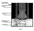
- One embodiment of this invention relates to designs and manufacturing techniques suitable for creating a practical, low cost, Thin Film Tissue Interface (TFTI) device that creates micropores using thermal energy produced by the passage of electrical current through resistive elements and methods of manufacturing and functional operation of the TFTI devices.
- TFTI devices create one or more micropores on a wide range of biological membranes.
- TFTIs have applications that include thermal microporation of human skin for the enhancement of analyte monitoring and delivery of permeants such as a therapeutic drug or a tattoo dye.
- TFTIs are characterized by their ability to rapidly and efficiently create a pattern or array of micropores on the surface of a biological membrane.
- the pattern may be any geometric spacing of micropores with pore densities as high as one pore every 0.2 square mm and covering a total porated area ranging from a few square millimeters to greater than several hundred square centimeters.
- TFTI devices are designed to be thin, flexible, conformable structures that form the interface between a biological membrane and the controller portion of the integrated device that supplies each poration element or electrode or other active component such as a piezo-transducer in the TFTI with the required electrical signal to effect the poration or other function of the TFTI such as, but not limited to, iontophoresis, sonophoresis, electroporation, or impedance measurement of the contacted tissue.
- TFTIs are flexible and able to conform to the shape of the targeted biological membranes.
- the TFTIs could be fabricated to be very thin, light in weight, and integrated with a reservoir and could also be connected to the controller, current source through an umbilical cable to allow a more user-friendly configuration.
- controllable active additional flux enhancement features such as, but not limited to, pressure modulation, mechanical manipulation, iontophoresis, electro-osmosis, sonophoresis or electroporation
- the activation of this additional flux control feature could be controlled by the remote controller module either in a preprogrammed fashion, a user controlled fashion via inputs to the controller, or in an automatic, closed loop fashion wherein the rate of infusion of a permeant is modulated as a function of the measured level of a selected analyte within or other measurable property of the organism.
- the other measurable property could include heart rate, blood pressure, temperature, respiration and skin surface conductivity.
- the rate of insulin infusion based on the real-time measurement of glucose concentrations in the interstitial fluid or serum of an organism.
- many of the electrically conductive traces comprising the TFTI could be used to serve multiple functions.
- the traces used to deliver the short pulses of current to the resistive poration elements to induce the thermal cycling could also be used as electrodes for an iontophoretic or electro-poration process, carried out after the micropores have been formed.
- This invention relates to a microporation device, comprising at least one reservoir and a tissue interface comprising at least one microporator and a substrate, wherein the microporator is located on or within the substrate.
- the substrate could be selected from the group consisting of a woven material, a film, a supporting layer and a sheet.
- the woven material could comprise conductive fibers and non-conductive fibers.
- the substrate comprises perforations.
- the microporator could be selected from the group consisting of a probe element capable of conductively delivering thermal energy via direct contact to a biological membrane to cause the ablation of some portion of the membrane deep enough to form a micropore, electro-mechanical actuator, a microlancet, an array of micro-needles or lancets, a sonic energy ablator, a laser ablation system, and a high pressure fluid jet puncturer; and the probe element could be selected from the group consisting of an electrically heated resistive element capable of ablating a biological membrane, an optically heated topical dye absorber layer and optically heated topical dye layer.
- the probe element could be selected from the group consisting of a preformed wire conductor, a deposited conductive material, a machined conductive material, a laser cut conductive material, an adhesive foil, an electroplated material, a screen-printed material and an etched conductive material. In some embodiments, the probe element could be destroyed while ablating the biological membrane.
- At least one microporator comprises multiple microporators.
- the multiple microporators are probe elements.
- the microporation device of this invention could comprise diodes for isolating the electrical circuits used for activating the probe elements.
- the microporation device could comprise two or more of the probe elements are connected in a parallel circuit configuration or a series circuit configuration or a combination thereof.
- the microporation device could comprise a material near the microporator, wherein the material could be capable of producing an exothermic or endothermic reaction.
- the microporation device could comprise a microactuator.
- the microacuator could be selected from the group consisting of electro-static microactuators, thermal bimorph microactuators, piezoelectric microactuators, electromagnetic microactuators, magneto-restrictive microactuators and shape memory alloy microactuators.
- the microporation device could comprise an electronic circuitry and a power source.
- the probe element could comprise a conductive wire and the substrate could comprise a non-conductive fabric.
- the conductive wire could be woven in the non-conductive fabric.
- the microporation device could comprise a plug material on the perforations.
- the plug material could comprise a volatile material.
- the substrate could be embossed.
- the microporation device could comprise an enhancer material for enhancing transmembrane transport of a fluid across the biological membrane.
- the microporation device could comprise multiple chambers.
- the multiple chambers could comprise different substances. At least one of the multiple chambers could be disposed after a single use of the microporation device.
- the multiple chambers could comprise at least first and second chambers, the first chamber comprising a first substance and the second chamber comprising a second substance.
- the first and second substances could be first and second biologically active agents.
- the first substance could be a dry formulation pharmaceutically active agent
- the second substance could be a diluent for reconstituting the dry formulation into a pharmaceutically acceptable liquid or gel formulation.
- the microporation device could be capable of transdermal delivery of a substance in the first chamber or withdrawal of an analyte transdermally into the second chamber.
- the microporation device could be capable of simultaneous transdermal delivery of a substance in the first chamber and withdrawal of an analyte transdermally into the second chamber.
- the substance could be insulin and the analyte could be glucose.
- the substances could be selected from the group consisting of bioactive peptides or proteins, therapeutic drugs, vaccines, pain medications, permeation enhancers and pH stabilizers.
- the different substances could be delivered by the microporation device in modulated amounts. At least one of the different substances could passively diffuse into the biological membrane.
- the substances which could be the same or different, could be delivered simultaneously, sequentially, alternately, or any combination thereof.
- the different substances could be delivered by the microporation device into the organism in adjacent locations in the biological membrane such that the different substances could combine and mix once they are within the tissue matrix of the organism.
- the microporation device could comprise an analyzer for detecting or quantitating the analyte.
- the microporation device could comprise a control module for controlling the delivery of the substance based on a quantitative value of the analyte detected by the analyzer.
- the microporation device could comprise a divider or valve disposed between the first and second chambers that prevents mixture of the first and second substances until the divider could be removed or the valve could be opened.
- the divider could be a membrane.
- the first substance could be a pharmaceutically active agent, and the second substance could a pharmaceutically acceptable carrier.
- the microporation device could comprise a flux enhancement microporation device, wherein the flux enhancement microporation device enhances a flux rate of a substance into the biological membrane.
- the flux enhancement microporation device enhances a flux rate of a substance into the biological membrane by a technique selected from the group consisting of iontophoresis, electroporation, electro-osmosis, sonophoresis, and pressurization.
- the microporation device could comprise a disposable component or the microporation device could be for a single use after which the microporation device could be discarded.
- the disposable component could treated with reagents which react with a biological fluid withdrawn from the biological membrane to produce a signal or measurable change in properties which could be predictably related to the quantity of an analyte within the biological fluid.
- the disposable component could be treated with one or any combination thereof of surfactants, hydrophilic or hydrophobic compounds.
- the disposable component could treated with antimicrobial or anticoagulent or protease inhibitor compounds.
- the disposable component could comprise stimuli-responsive polymer gel sections comprising a material that could be released by a thermal, chemical or electrical stimulus.
- the disposable component could comprise a material that releases a compound when heated.
- the microporation device could comprise a mixer located on or within the substrate, the mixer being capable of mixing a substance prior to transdermal delivery of a substance into the biological membrane.
- the microporation device could comprise a closed-loop delivery and monitoring system, wherein the closed-loop delivery and monitoring system is capable of modulating transdermal delivery of a substance through a biological membrane based on a value of a property of an animal.
- Another embodiment of this invention is a method of manufacturing a microporation device, comprising obtaining a substrate and forming a conductive network on the substrate, wherein the conductive network provides electrical connections to a microporator.
- the method could comprise bonding an adhesive layer over the conductive network.
- the method could comprise forming a non-conductive plug on the perforations.
- the method could comprise bonding the conductive network to a reservoir.
- Another embodiment is a method for forming openings in a biological membrane, comprising placing a microporation device in close proximity of the biological membrane and triggering the microporation device to form at least one opening in the biological membrane, the microporation device, comprising at least one reservoir and a tissue interface comprising at least one microporator and a substrate, wherein the microporator is located on or within the substrate.
- the triggering could transfer heat to the biological membrane.
- the opening could have a diameter of 1-1,000 microns.
- the opening or artificial pore could be formed by a method selected from the group consisting of local heating, mechanical puncture, sonic energy, hydraulic puncture, and electroporation.
- the method could comprise any one or more of the following: (a) applying an enhancer to the opening; (b) applying a permeant to the opening; (c) collecting a fluid from the opening; (d) monitoring an analyte in the fluid; (e) delivering a substance into the biological membrane; (f) mixing a substance prior to delivery of a substance into the biological membrane; and (g) delivering a substance into the biological membrane and collecting a fluid from the biological membrane.
- An object of this invention is a method for administering a compound through a biological membrane to an underlying tissue matrix or obtaining a biological fluid sample from a tissue matrix underlying a biological membrane, comprising a) contacting a flux enhancement cell with a biological membrane, b) forming a seal between the outer wall and the membrane, wherein the reservoir outlet is in communication with an artificial pore in the membrane; c) applying positive pressure to the inner cavity of the reservoir; d) biasing the reservoir towards the membrane, thereby producing the compressed state of the membrane; e) biasing the reservoir away from the membrane, thereby producing the relieved state; and i) the biological membrane having an inner surface in intimate contact with the tissue matrix and an outer surface, thereby producing the relieved state, wherein the biological membrane has a resting state, a pressurized state in which the outer surface of the membrane is depressed to a substantially concave form relative to the resting state and the underlying tissue matrix is compressed, and a relieved state, wherein the outer surface of the membrane is biased into
- One embodiment of the method for administering a compound through a biological membrane to an underlying tissue matrix or obtaining a biological fluid sample from a tissue matrix underlying a biological membrane comprises g) biasing the reservoir towards the membrane, thereby producing the compressed state of the membrane; h) biasing the reservoir away from the membrane.
- Another object of this invention is a flux enhancement device comprising an outer wall, the outer wall defining a cell cavity; and a reservoir comprising an inner cavity and an outlet, wherein the reservoir is movably contained within the cell cavity.
- the reservoir could be movably linked to the outer wall with a compliant membrane.
- the flux enhancement device could comprise a microporator.
- the microporation device or flux enhancement device could comprise a closed-loop delivery and monitoring system, wherein the closed-loop delivery and monitoring system is capable of transdermal delivery of a substance through a biological membrane and withdrawal of an analyte transdermally through the biological membrane.
- the flux enhancement device could comprise could comprise a closed-loop delivery and monitoring system, wherein the closed-loop delivery and monitoring system is capable of modulating transdermal delivery of a substance through a biological membrane based on a value of a property of an animal.
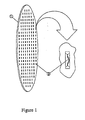
- FIG 1 shows the general configuration of a TFTI (1) with plurality of poration elements (2).
- the microporators of a TFTI device are heated probe elements capable of conductively delivering thermal energy via direct contact to a biological membrane to cause the ablation of some portion of the membrane deep enough to form micropores.
- the poration elements (2) are resistive elements.
- the resistive elements could take almost any shape, but are typically high aspect ratio, straight cylinders or bars with diameters or square cross-sections that range from 1 micron to 150 microns and lengths from 100 microns to 3000 microns respectively.
- the pulsed element could be controllably and rapidly brought to a specified high temperature, ranging from 120°C to greater than 3000°C (the upper limit is really set by the melting point of the material comprising the resistive element, for most tungsten alloys this is in excess of 3000°C), whereupon this thermal energy could then be delivered to the contacting tissue to effect the thermal poration of the tissue.
- the patterned array of resistive elements is connected to a conductive network that passes electrical energy to each of the resistive elements.
- the array of resistive elements are connected to the current pulse source either individually, as a series electrical system, parallel electrical system or some combination thereof.
- the instantaneous current required for the operation of the TFTIs depends mainly on the number of resistive elements in a device, parallel or series network configuration and size of the resistive elements.
- Instantaneous current flowing through the resistive element network could range from 1 milliamps to 40 amps, however, as the pulse duration is typically only a few milliseconds long, and the impedance of each element is quite low (in practice the typical resistance of a single tungsten alloy poration element has been measured to be less than 0.1 ohms) the average power requirements are quite modest.
- the resistive elements are arranged in a two-dimensional pattern that is transferred directly to the surface of a biological membrane.
- the type of pattern produced is dependent on the application.
- a set of micropores designed to deliver a local anesthetic to an IV insertion site may have a narrow pore pattern beginning at the needle insertion site and extending along the expected path of the needle.
- the desired pore depth is also dependent on the application.
- the pore depths formed may be designed to be relatively shallow at the needle insertion site and deeper along the needles path within the body.
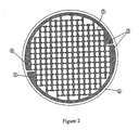
- FIG. 2 shows one embodiment of a parallel conductive network (3) with anode side (4), cathode side (5), poration elements (2) and supporting substrate (6).
- Each TFTI could be connected to an external electronic control module to supply electrical energy with the required current and pulse duration parameters.
- the mechanism that forms a micropore is a result of the intimate contact of the biological membrane with the resistively heated element.
- the TFTI would have resistive elements that stayed in contact with the skin before, during and after the poration process without moving. This would be known as a non-actuated poration process where resistive elements remain passively in the same location within the apparatus.
- the devices using micro-actuation combined with the resistive elements would be known as actuated microporation or actuation of poration elements.
- the mechanism that forms a micropore is a result of the intimate contact of the biological membrane with the resistively heated element.
- the TFTI of Figure 2 would have resistive elements that stayed in contact with the skin before during and after the poration process without moving. This is known as a non-actuated poration process where resistive elements remain passively in the same location within the apparatus.
- micro-actuation combined with the resistive elements and is known as actuated thermal microporation or actuation of poration elements.
- Micro-actuators produce a mechanical actuation of the poration elements and achieve greater control over pore depth, act to remove the resistive element from the micropore once it has been formed or perform a function such as opening a barrier that isolates a reservoir.
- An illustrative embodiment of an actuated microporator is shown in Figure 3, which shows a wire resistive element in the unheated position (7) and the heated position (8).
- the actuated microporator of Figure 3 is a straight tungsten wire element.
- Figure 3 shows that the straight tungsten wire element undergoes a significouldt increase in length from position (7) to position (8) during the heating pulse as a result of the wires coefficient of thermal expansion as it undergoes the dramatic change in temperature of a typical thermal poration cycle.
- the anode side (4) and the cathode side (5) of the wire element are immobile and the wire reacts to the heating pulse by bending outward to accommodate its thermally induced increased length, away from the original centerline of the element.
- the direction of the wire motion could be designed to be directed away from the substrate (6) by forming a small initial bend in the poration element when in the unheated position.
- micropores could be created without requiring an initial intimate contact between the biological membrane and the poration element. That is, when the poration element is heated and subsequently is actuated to move towards the biological tissue surface, the necessary contact between the poration element and the biological surface could be ensured by designing the geometries of the system and the amount of actuation travel to guarantee the required physical contact.
- the choice of wire element length, initial bend and wire temperature could be used to control the resulting pore depth in the biological membrane as well.
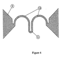
- FIG 4 Another embodiment of an actuated microporator of this invention is shown in Figure 4, wherein the actuated element is formed from a thin sheet of element material (9) such as tungsten. Some of the element material is removed using a process such as laser micromachining to produce the resistive element shown in Figure 4. During the laser micromachining process, it is possible to dynamically monitor the impedance of each poration element as it is formed. By using this sort of dynamically monitored fabrication process, a parallel or series array of poration elements could be formed wherein it could be ensured that the current pulse delivered is distributed in a balanced, uniform manner to each individual element. The shape of this resistive element was chosen to produce motion in the direction perpendicular to the plane of the sheet material during heating.
- element material such as tungsten.
- the physical expansion of the curved sections (10) of the structure force the tip (11) of the element to lift away from the plane of the sheet material. Since the entire element reaches a high temperature, the tip (11) ablates tissue as it is forced into the biological membrane. The resulting pore depth in this case is controlled by the arc length of the curved sections (10), length of the tip region (11) and element temperature.
- the specific thermal coefficient of resistance for the resistive poration element could be selected or designed such that as the individual element heats up, its resistance increases, thereby causing less current to flow in that specific poration element within a parallel network and at the same time forcing more current to go to the other poration elements in this same network.
- a self-balancing parallel network of resistive elements could more easily be designed and manufactured. This is similar to how a standard parallel wiring of a home lighting system operates when several incoulddescent lamps are connected on the same circuit.
- shape memory alloy (SMA) materials are used for the body of the resistive element.
- SMA materials has the potential to maximize the efficiency and effectiveness of actuated poration.
- micro-actuators could be used for the purpose of actuated poration. Manufacturing methods that employ more advanced processes such as photolithography are capable of producing more complex micro-actuators.
- Some micro-electromechanical systems that could be incorporated into TFTI devices include but are not limited to electro-static microactuators, thermal bimorph microactuators, piezoelectric microactuators, electromagnetic microactuators and SMA microactuators.
- Fusible TFTI designs are an alternative to actuated and non-actuated poration schemes.
- a fusible design enough electrical energy is passed through the resistive element to destroy the element, taking it out of the electrical circuit. This also provides a mechanism of removing the element from the pore site.
- This embodiment of the invention also has the potential to greatly simplify the supporting electronics requirements.
- the driving electronics are required to generate a signal of controlled duration and amplitude for sensation management.
- the thermal pulse duration could be controlled mainly by the physical failure properties of the element and the electronics are only required to deliver an impulsive signal with uncontrolled duration, as in the case of a capacitor discharging.
- a more preferable method may be to fabricate the substrate holding the element out of a material which has been specified to undergo a thermal shrinking or tearing process when exposed to the elevation of temperature due to the activation of the poration element.
- this process could be made to occur at much lower, and more biocompatible temperatures, than what might be required if one were to simply 'blow the fuse'.
- Some materials that have this type of desired thermal properties are the heat-shrinkable polymers and vinyls commonly used in electrical insulation.
- this substrate could be formed with a small etch line, embossed stress point, or other such feature to provide the 'flaw' from which the thermally induce tear would originate.
- Another significouldt advantage of this type of thermally induced tearing is that the opening of the pore into a drug or assay containing reservoir could be produced with only a minimal amount of temperature for a very short period of time, minimizing the amount of thermal energy and peak temperature being presented to the reservoir. This feature is of particular importance when the reservoir contains thermally fragile peptides, proteins, assay enzymes or other drugs sensitive to thermal stress.
- the TFTI devices of this invention could also be enhanced by the addition of a range of substances at or near the poration element. This approach also has particular utility with elements that are fusible as previously described. The object of these substances is to produce a chemical reaction at the pore sites and during the poration process.
- This chemical reaction could be tailored to perform a variety of functions.
- One example is coating an element with a pyrotechnic material or other material that results in an exothermic reaction. The energy used to ablate tissue would then come mainly from the exothermic reaction. This allows a simple way to reduce the electrical energy required to trigger poration and thus reduce the overall size of the integrated device.
- a second example is a combined exothermic and endothermic reaction. An initial exothermic reaction would produce a micropore and be followed closely by an endothermic reaction to cool the pore site and improve sensation experienced by patients.
- a chemical reaction at the pore site could also be useful for the byproducts of the reaction.
- byproducts could perform all or some of the functions of flux enhancers, anti-clogging agents, permeants, therapeutic agents, reactants to drive subsequent reactions or other beneficial purposes.
- the TFTIs comprising a resistive element could be manufactured by different methods.
- the first method uses a previously formed wire conductor to create the resistive element.
- the resistive elements are created by a deposition of conductive material.
- the resistive elements are formed by etching or machining of the element material.
- some manufacturing methods employ both deposition and etching.
- Example 1 A Woven Material TFTI Device
- Some embodiments of the TFTI devices involve the use of previously manufactured wire conductors such as tungsten, tantalum, or tungsten alloy wire as the resistive element.
- wire conductors such as tungsten, tantalum, or tungsten alloy wire
- methods for incorporating the wire conductors into a TFTI design include, but are not limited to weaving, sewing, bonding, brazing, spot welding, connecting with conductive adhesives or resins and laminating to a thin film or laminated structure.
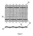
- the basis of a woven material TFTI device is a hybrid woven fabric such as what is shown in Figure 5.
- Figure 5 is an enlargement of a section of the hybrid woven fabric and should be considered as extending outward in two dimensions as a repeating structure.
- the hybrid woven fabric contains a combination of structural fibers (10) and (11) which are not electrically conductive (such as polyester, fiberglass, nylon, mylar, polycarbonate, or the like) and electrically conductive fibers or strands (12) (such as tungsten or tantalum wires, conductive polymers, glass or carbon fibers, or the like).
- polyester fibers of 50-micron (10) and 80 micron (11) diameters are woven with 50-micron diameter tungsten wire (12).
- the electrically conductive fibers or strands are woven into the fabric and run in only one of the weave directions, spaced apart by a specific number of structural fibers depending on the desired poration element array density.
- the number of polyester fibers between two tungsten wires is 28 that would result in an element spacing of about 1.4 millimeters.
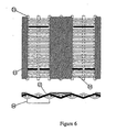
- the woven material is then processed to apply conductive traces on one side as shown in Figure 6, creating the desired conductive network (13) with the interwoven conductive fibers forming the resistive elements (14).
- These traces may be created in a variety of ways including: pressure transfer of conductive/self adhesive foils onto this surface; electroplating into the desired pattern using either a shadow mask or resist mask to define the traces; or simply screen-printing with electrically conductive ink or resins and curing. Most conductive inks are designed to allow a certain amount of flexibility after curing which results in a more compliant TFTI device.
- the conductive network in Figure 6 is arranged as a parallel electrical circuit although series or combined series and parallel configurations could be accommodated by this design.
- a silver impregnated epoxy is used to form the conductive network that is applied using standard screen-printing techniques.
- woven material TFTI devices An added advantage of the woven material TFTI devices is that proper choice of conductor thread count would result in resistive elements on both sides of the TFTI. This results in the optional use of the TFTI to breach or open a drug reservoir simultaneously with the creation of micropores. Areas of the fabric that are not covered by the conductive network would then be able to pass a deliverable substance from a drug reservoir, through the TFTI and into the micropores.
- TFTI TFTI-binding to a drug reservoir or addition of an adhesive layer to maintain contact between the TFTI and the biological membrane to be porated.
- This design is also conducive to the integration of other functional features that include iontophoretic electrodes, flux enhancer releasing elements, buffer releasing elements, analyte assay electrodes.
- the analyte assay process could also be accomplished via optical means by looking for a colorimetric shift in response to the selected analyte's concentration.
- Example 2 A Wire Overlay TFTI Device
- This TFTI design utilizes a unique screen-printing process that involves overlaying wires on a substrate and then printing conductive traces over the wires to both form electrical connections with the conductive network and bond the wires to the substrate.
- This example design also uses SMA wire as the resistive element material to produce an optimized actuation of the poration element.
- the poration elements are designed to alter their shape during the poration process and breach a drug reservoir directly over the pore site.
- SMA wire (15) such as nitinol are mounted in a frame (16) with a spacing given by the desired element density in the final array. A spacing of 1.00 mm between lengths of SMA wire is used.
- the frame and mounted wires are then placed over a thin film substrate (17) and standard screen-printing techniques are used to deposit conductive ink (18) onto the substrate and SMA wire combination to produce an electronic network.
- the SMA material chosen for this application should have a high melting point such as nitinol.
- the substrate material must be non-conductive and have a low melting point such as polyester.
- a good coulddidate conductive ink should have a high conductivity and be flexible after it is fully cured such as a silver/polymer conductive ink.
- FIG. 8a shows an enlarged side view of a single poration element after the screen-printing process and before embossing occurs.
- a dielectric or adhesive layer (19) prevents the conductive ink network from making contact with the skin or other biological membrane.
- Figure 8b shows an element after it has been embossed. It is important that the embossing process does not cause the SMA material to anneal or undergo a change in crystal structure. This would allow the SMA material to return to its original shape (straight) when heated resistively by the conductive network as shown in Figure 8c. As an element becomes heated, it initially creates a skin pore due to intimate contact with the surface of the skin. As further heating of the element occurs, the SMA material begins to return to its original shape and retract from the newly created pore while simultaneously forming an opening in the embossed feature (20) of the supporting substrate. This could then open a pathway between a reservoir on the opposite side of the substrate and the microscopic pore as described above.
- Some embodiments of the TFTI devices involve resistive elements that are deposited by processes such as electro-discharge machining(EDM), sputtering, screen-printing, electroplating and chemical vapor deposition (CVD) that are common to the flexible circuit and electronic industries.
- EDM electro-discharge machining
- CVD chemical vapor deposition
- Example 3 A Sputter Deposited TFTI Device
- the first step involved in manufacturing is the deposition of a material such as tantalum by sputtering to form the resistive elements and conductive network on an appropriate substrate such as 50-micron polyamide.
- Figure 9 shows the pattern of deposited tantalum traces (21) on the polyamide substrate (22).
- a parallel electrical configuration is used for purposes of illustration, however the conductive network could be designed to address each poration element single or in a parallel circuit, series circuit or any combination of parallel and series circuits.
- FIG 10 shows an enlarged side view of a single resistive element (23) at different points in the manufacturing process with adjacent conductive network connections (24).
- Figure 10a shows the element after the initial deposition and an optionally additional layer over the conductive network (25).
- the next step in the manufacturing process is the placement, screening or bonding of an adhesive layer (26) over the conductive network without covering the resistive elements as shown in Figure 10b.
- the purpose of the adhesive layer is to bond the biological membrane such as skin to the TFTI and ensure that there is intimate contact with the resistive elements.
- the final step in the manufacture of the TFTI is optionally embossing in the area of the resistive elements as shown in Figure 10c.
- the purpose of embossing is to move the resistive element near or even proud of the adhesive, biological membrane contacting side of the TFTI and ensure intimate contact between the resistive element and the biological membrane to be microporated.
- the embossing process could also serve to thin the substrate material in the area of the resistive element.
- Some embodiments of the TFTI devices involve resistive elements that are etched or machined from a layer or sheet of material by processes such as laser micromachining and a range of photolithography techniques common to experimental MEMS devices and the electronics industry.
- the following section illustrates a TFTI device that could be manufactured using a micromachining process.
- Example 4 A Micromachined TFTI Device
- Figure 11 shows an enlarged side view of a single resistive element at different points in the manufacturing process.
- the first step in the manufacturing process is to laminate thin films of the resistive element material (27) such as tungsten in a 30 micron sheet to a supportive or resistance tailoring layer such as copper (28) in a 50 micron sheet. These layers are then micromachined using a laser from the tungsten side as shown in Figure 11a. Laser power, repetition rate and cutting speed are adjusted so that the resistive elements (29) and conductive network (30) are produced without cutting through the supportive or resistive tailoring layer. Also, during this process of laser micromachining, the laser energy could be used to effectively form the electrical bonds between the tungsten poration elements and the resistance-tailoring layer.
- the resistive element material such as tungsten in a 30 micron sheet
- a supportive or resistance tailoring layer such as copper (28) in a 50 micron sheet.
- the next step shown in Figure 11b is to bond the tungsten side of the structure in Figure 11a to a nonconductive layer such as polyester (31).
- This laminated structure is then laser micromachined from the copper side (28). At this point the copper is no longer needed as a structural support.
- the result of this process is to leave copper material on the conductive network only and remove it from other locations including over the resistive elements. Care is taken in the laser parameter settings to avoid cutting through the nonconductive layer (31).
- the next step in the process is to bond an adhesive layer (32) over the conductive network with the resulting structure shown in Figure 11c.
- the final step in the manufacturing process is to emboss the nonconductive layer at the locations of the resistive elements as shown in Figure 11d.
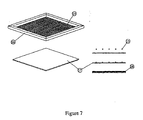
- Example 5 A Simple Screened TFTI Device
- the following example utilizes screen-printing almost entirely to form the TFTI device.
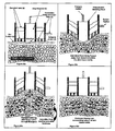
- a 20-micron thick polycarbonate sheet (33) is obtained and about 10-20 micron diameter perforations (34) are made in the sheet as shown in Figure 12.
- the perforations (34) could be made by laser processing, mechanical punching or other method for perforating a sheet.
- the perforations could be of any shape ranging from 1 micron to several millimeters.
- the perforations are generated in tight groups, with multiple tight groups forming a larger array.
- the next step is to screen-print a conductive network (35) without elements onto the polycarbonate sheet as shown in Figure 13.
- the conductive network may be formed using silver conductive ink in a flexible when cured carrier and allowed to cure.
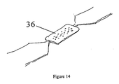
- a low melting point, nonconductive plug material such as wax (36) is screened over the perforations to seal them as shown in Figure 14.
- additional conductive ink (37) is screened to form a fine bridge of material connecting the two sides of the conductive network over each wax plug as shown in Figure 15. This is the resistive element that becomes heated during the poration process.
- the conductive ink used to form the resistive poration element may be the same as that used to form the conductive network or it may be selected to be of a different material, such as a carbon conductive ink, to be more suitable for this design purpose.
- This design functions by creating a micropore initially and then further heating removes the plug material by either a melting process or the thermal ripping or tearing process described previously and opens a pathway between the micropore and a reservoir.
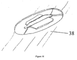
- the final step in manufacturing the TFTI is to screen an adhesive (38) as shown in Figure 16 to ensure intimate contact between each resistive element and the biological membrane to be porated and also to act as the principal attachment mechanism of the device to the subject's body.
- any of the TFTI designs discussed here could be designed to allow for individually addressable resistive elements.
- the addition of diodes to the conductive network would allow current directional isolation of individual array elements which supports some schemes by which individual elements could be activated with a 'row-column' addressing approach, similar to how an individual pixel might be toggled in a two dimensional visual array.
- An integrated device design that used separate reservoirs for each poration element could benefit from an individually addressable poration element control scheme.
- Another advantage of this approach is an overall reduction in the peak power required to activate the TFTIs. The maximum peak current required to effect poration would be smaller than that if single elements were activated one at a time.
- each cell comprising a poration element and its associated micro-reservoir being essentially individual, independently controlled systems, one could program the controller system to only activate a certain number of these cells at a time, allowing more control over a drug delivery profile or when the cells are used to effect the assay of an analyte, individual assays may be made at various selected points in time.
- a feature of the TFTI designs of this invention is that manufacturing processes are used that allow the technology to be scaled down drastically. Techniques such as photolithography are able to produce TFTI designs with high densities of extremely small poration elements. Scaling down the size of poration elements has potential advantages such as reduced energy required for poration, improved skin surface healing and improved patient sensation.
- the devices of this invention could be manufactured using micro-electromechanical systems (MEMS) manufacturing technology.
- MEMS micro-electromechanical systems
- the micromanufacturing technology is suitable for cost-effective mass production.
- microactuators could be designed to deliver permeants by individual pore microinjectors.
- the microinjectors could be made integrally with the resistive element so that the microinjector body thermally ablated tissue, extended into the skin layer and delivered a short-duration, high pressure fluid injection on a microscopic level.
- microsystem technology could be applied to TFTI designs is in the area of tattoo removal.
- An array of micromachines could be designed to progressively lift up microscopic flaps of skin and remove dye-bearing tissues.
- a closed loop control scheme could be used where integrated microsensors detect the location of dye bearing tissues, a microprocessor then determines the best course of action.
- TFTI device uses sensors and actuators in the same TFTI device to create extremely sophisticated and intelligent microsystems.
- a single TFTI device could be built that drew interstitial fluid from pore sites and assayed for a particular analyte (such as glucose) and also delivered a substance through other pores (such as insulin) based on the results of the analyte measurement.
- analyte such as glucose
- insulin a substance through other pores
- Example 6 Integrated Tissue Poration and Drug Delivery Device
- the microporation device of this invention could be used as an integrated device for the creation of small holes or perforations or micropores in tissue, the delivery of drugs or other permeants through the micropores, the extraction of biological fluids through the micropores, and the assaying of analytes in an extracted biological fluid or permeants to be delivered.
- the integrated device is a multi-component device comprising a tissue-interface layer comprising at least one microporator and at least one reservoir, one or more distinct reservoirs, a power supply, batteries, electronics, display and case.
- Figure 17 shows one embodiment of a single or a multi-component device of this invention showing a thin cap (39) that form the outer body of the device, a controller board (40) that contains driving electronics and a battery, a thin film top plate (41) and reservoir wall (42) that forms the top and sides of the chambers that contain the permeant for delivery. Finally a TFTI device (43) forms the bottom of the permeant chamber.
- top plate (41), reservoir wall (42) and TFTI device (43) are bonded together to form the disposable portion of the device containing the permeants for delivery.
- the disposable (41-43) and the controller board (40) are designed to fit completely into the thin cap (39) with the TFTI exposed on the bottom surface of the device.
- One embodiment of the device is a single, disposable unit.
- An alternate embodiment has a subset of the components incorporated into a disposable portion while the remainder of the components is reusable.
- the device may be manufactured in more than one version, for example a personal version or a clinical version, with slightly different formats but similar functions. Some versions would be effective with fewer components and a reduced functionality. All versions would be discrete and small (on the order of one half (0.5) to ten (10) cubic inches).
- the tissue interface layer comprises some or all of the following: elements for effecting the poration of the tissue, adhesive for attaching the device to the tissue, reservoirs containing permeants for delivery, reservoirs for holding extracted biological fluids, and reagents for assaying an analyte.
- the tissue interface layer could also include hydrophilic and hydrophobic surface treatments to act as fluid flow modifiers for controlling the motion of liquid permeants or biological fluids collected.
- the tissue interface layer may also incorporate antimicrobial agents to prevent sepsis or anticlotting or anticoagulents to control the aggregation of permeants or biological fluids extracted.
- the tissue interface layer may also be treated with permeation enhancers or buffers used for pH stabilization.
- the tissue interface layer may contain stimuli-responsive polymer gel sections, saturated with beneficial permeants, which could be triggered to release the beneficial permeants through a thermal, chemical or electrical stimulus.
- the tissue interface layer may release beneficial permeants on demand when heated, for example by the poration elements or other similar elements on the tissue interface layer.
- the tissue interface layer may contain piezoelectric elements for delivery of acoustic energy into the tissue or permeants being delivered or biological fluids being extracted.
- the tissue interface layer is intended to become part of a disposable as shown in Figures 18 and 20 or may be permanently mounted in the integrated device as in Figure 19.
- Figure. 18 shows one embodiment of the integrated device showing the poration elements 44, conductive traces to the elements 45, the adhesive layer 46 with holes beneath the poration elements 44 and a single permeant reservoir 47.
- FIG 19 shows one embodiment of the integrated device where the entire device is disposable.
- the poration elements, adhesive layer and permeant reservoir (all represented as 48) are permanently installed in the device.
- This embodiment has two control buttons 49 on the upper surface of the case. Pressing one button would initiate the poration process and basal delivery of the permeant. Pressing the other button would deliver an additional preset amount of permeant.
- Figure 20 shows an embodiment of the integrated device having a reusable component 50 and a disposable component 51.
- the reusable component 50 contains a permeant reservoir 53 and a skin interface 52. Batteries and circuits are housed in the reusable component 50. After a single use, the disposable component 51 would be replaced, thereby replenishing the permeant, the poration elements, and the adhesive which are all parts of the skin interface 52.
- poration elements In addition to the poration elements, other conductive traces or wires may be incorporated into the tissue interface layer to act as all or some of the electrodes for electroporation iontophoretically enhanced delivery of a permeant into the tissue or for the enhancement of the extraction of biological fluids from the tissue for the purpose of monitoring one or more analytes. These electrodes may also be used to provide all or part of the current path via which one may deliver pulses of electrical energy into the tissue for the purpose of electroporating selected tissues within the current path. These electrodes may also be used for sensing through a drop in impedance that poration has occurred. Electrically conductive poration elements themselves could be used as one of the electrodes for either iontophoresis, or electroporation, or impedance sensing.
- the tissue interface layer may comprise one or more reservoirs. In the case of multiple reservoirs, these reservoirs could be used to keep different and perhaps incompatible permeants separate. Delivery of permeants from the reservoirs could be simultaneously or sequentially.
- a reservoir wall is typically "porated” to breach the reservoir membrane and allow the delivery of the permeant into the tissue. This poration of the reservoir is accomplished with the same type of poration elements as are used to porate the tissue. Prior to the breach of this reservoir, the reservoir could maintain a stable, sealed, and sterile environment for the permeant, allowing the entire disposable portion of the integrated device to be manufactured and packaged efficiently and economically. The breaching of the reservoir may occur before, coincidentally with or after the poration of the tissue as required.
- the flux rate of a permeant from a particular reservoir into the tissue is proportional to the area of the micropore coupling the reservoir to the biological membrane, if all other factors such as micropore density or iontophoretic current are the same.
- a reservoir could initially be empty or contain an absorbent material, in order to serve as a storage location for extracted biological fluids. Reagents for the assay of an analyte in the biological fluid would typically be located at the entrance to the extracted biological fluid storage reservoir.
- the electronics for controlling the device are responsible for initiating the poration process, controlling the timing and amounts of permeants delivered, enforcing limits on the delivery mechanisms, processing the data for analyte assay and environment sensing, control of piezoelectric elements, and control of the user interface display if any.
- Environment sensing could include temperature, humidity, and pressure. These values, particularly the temperature, could affect the results of assays performed by the device.
- Some embodiments require or are facilitated by providing information to the user.
- a display is provided on the top of the case.
- Example 6A Passive Vaccine Delivery Device
- This embodiment of the device would be used in a clinical setting, where a patient receives a disposable patch that delivers the vaccine by diffusion through the micropores over a number of hours or days.
- the disposable for this embodiment would be simple, small, thin and inexpensive.
- the disposable would consist of a thin sealed reservoir with thermal poration elements and adhesive on the bottom and electrical contact pads on the top. The contact pads are attached to traces that lead to the thermal poration elements.
- the reservoir contains the vaccine to be delivered.
- the disposable is inserted into the reusable component of the device in a clinical setting. The entire device is placed against the surface of the skin so that the adhesive fixes the disposable to the surface of the skin.
- the thermal poration elements are activated, porating the surface of the skin and simultaneously breaching the lower surface of the reservoir allowing the vaccine to flow down and into the micropores.
- the reusable component of the device is then removed from the disposable portion, leaving the disposable portion attached to the surface of the skin and precisely registered to the micropores, allowing the vaccine to passively diffuse into the skin until the disposable is removed and discarded.
- This method for delivering a vaccine antigen has particular advantages in that the portion of the autoimmune system optimally targeted by an antigen to induce the best antibody response is the langerhans cells or dendritic cells. These langerhans cells or dendritic cells exist within the epidermis, exactly those tissues to which this method of delivery places the permeant being delivered.
- Example 6B On-demand pain medication delivery
- the device comprises a reservoir for hydromorphone or other suitable opiate, circuitry required to support the thermal poration process, circuitry required to support the iontophoretic delivery of the hydromorphone, adhesive for attaching the device to the surface of the skin, thermal poration elements, a button to initiate delivery and a button for breakthrough pain dosing.
- the device has at least one counter electrode pad that contacts the skin while the device is used.
- the poration elements are used as the delivery electrodes after the poration step.
- the device is placed against the surface of the skin so that the adhesive fixes the device to the surface of the skin.
- the initiation button is pressed, activating the thermal poration elements, porating the surface of the skin and simultaneously breaching the lower surface of the reservoir allowing the hydromorphone to flow down and into the micropores.
- Iontophoretic delivery of the hydromorphone at a basal delivery rate commences.
- the patient presses the other button on the surface of the device that temporarily increases the iontophoretic current to deliver a burst of hydromorphone. After many hours or days, the entire device is removed and discarded.
- This embodiment of the integrated device comprises a reservoir for a drug, another reservoir for a capillary permeability enhancer such as NH 3 , and another reservoir for a pH-neutralizing compound.
- the device includes thermal poration elements, circuitry required to support the thermal poration of the tissue, circuitry required to support the thermal poration or breaching of the reservoir walls, circuitry required to support the iontophoretic delivery of the permeants, and adhesive for attaching the device to the surface of the skin.
- the device has at least one counter-electrode pad which contacts the skin while the device is being used.
- the poration elements are used as the delivery electrodes after the poration step.
- the device is placed against the surface of the skin so that the adhesive fixes the device to the surface of the skin.
- the thermal poration elements are activated, porating the surface of the skin and simultaneously breaching the lower surface of the reservoir containing the NH 3 . Additional poration elements are used to heat the NH 3 reservoir, creating gaseous NH 3 and water.
- the drug reservoir is breached and the drug is iontophoretically delivered.
- An iontophoretic current slowly alters the pH of the tissue, possibly interfering with further iontophoretic delivery as well as irritating the tissue, so after a period of minutes the pH neutralizing reservoir is breached and some pH neutralizer is delivered into the tissue to bring the pore interface zone back to near physiological pH of 7.2. Alternate delivery of drug and pH neutralizer continues as necessary to delivery the desired amount of drug.
- microporation device of this invention could be used as an integrated device in conjunction with a pressure modulation and flux enhancer.
- the pressure modulation and flux enhancer could be used as a stand-alone device or in conjunction with any other device, preferably medical devices.
- the pressure modulation and flux enhancer of this invention utilizes pressure modulation to increase transmembrane flux through one or more micropores in the membrane. Forced compressions followed by forced expansions of the tissue matrix underlying the membrane are applied in a coordinated fashion with pressure or suction from within the reservoir attached to the outer surface.
- the devices may be used to perform flux enhancement.
- the devices would have at least one flux enhancement cell, and certain preferred embodiments would comprise multiple cells joined into a single array.
- the flux cells may be arranged to work synchronously (e.g., by "parallel" cell function, delivering the permeant(s) from a plurality of cells at the same time), for example by synchronous control of individual actuators or by use of actuators which act on multiple cells.
- Such devices may be used to administer a single permeant, particularly when a large dose of the permeant is required, or to administer different permeants, where combination therapy is desired.
- multi-cell devices may be arranged such that the various cells act asynchronously or even perform different functions.
- a multi-cell device may comprise cells with different drugs which are administered on different schedules, or may comprise cells with different functions, such as a device comprising cells for delivery of a permeant as well as cells for sampling of fluid from the tissue matrix.
- a single flux enhancement cell would have an outer wall or an outer annulus (61) defining a cell cavity (62), with the cavity open at least one end. This open end interfaces with the biological membrane (74) having a micropore (73) during use of the device.
- the outer wall is typically in the shape of a hollow cylinder having at least one open end, although polygonal cross-sections are also contemplated.
- the outer wall is substantially upstanding, and has an edge bounding the cavity (63, the "membrane interface edge").
- a reservoir (64) defining an inner cavity or a central portion (65) is movably contained in the cavity.
- the reservoir contains the permeant (66).
- the reservoir has an outlet (67), which is oriented towards the open (membrane interface) end of the cavity.
- a compliant membrane (68) spans the gap between the reservoir and the outer wall at the membrane interface end of the cavity.
- An additional compliant membrane (69) may also be included to form a pressure chamber defined by the reservoir wall, the outer wall, and the compliant membranes.
- the compliant membrane may additionally be coated with an adhesive (70), to promote a seal with the biological membrane.
- the membrane interface edge of the outer wall, and the end of the reservoir with the outlet are coated with an adhesive.
- the reservoir and the outer wall may additionally comprise controllable pressure ports (71, 72), through which the pressure in the cell cavity and inner cavity, respectively, may be modulated.
- Underneath the biological membrane (74) is cell matrix (75) and biological fluid (76) in the space between the cell matrix (75).
- the flux enhancement device is operated as shown sequentially in Figure 22.
- Figure 22a shows the initial 'neutral' stage of the systems pressure modulation cycle.
- Figure 22a shows a single cell of a flux enhancement device, which could be a single-cell or a multiple-cell flux enhancement device. The single cell is adhered to the skin surface of the biological membrane by an adhesive.
- Figure 22b shows the blanching, or second, stage of the pressure modulation cycle. While gradually increasing the pressure in the reservoir, the entire area of the biological membrane surrounding the micropore(s) is depressed into the underlying skin tissue by pushing the central portion. As the force pushing the central portion increases, it forces the device to assume a conical shape, pressing into the targeted tissue, as shown in Figure 22b. This produces two effects. First, by pushing the device on the biological membrane, the seal between the fluid reservoir and the skin surface becomes stronger, allowing a higher pressure to be maintained within this reservoir minimizing the possibility of a fluid leak. Second, the cell matrix under the skin tissue is compressed, forcing much of the fluid trapped within it between the cells out into the neighboring areas.
- Figure 22c shows the tissue expansion, or third stage of the pressure modulation cycle.
- the central portion of the device is now pulled away from the skin tissue surface while the compliant annular portion is kept attached to the surface of the skin by a suitable adhesive, a mild pneumatic suction or vacuum, or some combination of these methods.
- the pressure in the reservoir is dropped to ambient levels to ensure no leaks are formed from the central reservoir holding the drug payload.
- the decompressed state of the recently blanched skin cell tissue matrix directly beneath the micropore would induce fluid from the drug reservoir to flow through the pore into these skin tissues beneath the porated surface.
- Figure 22d shows return to neutral, or fourth stage of the pressure modulation cycle.
- the central portion of the device surrounding the micropore(s) is now returned back to the neutral position, while simultaneously increasing the pressure in the reservoir slightly, as allowed while ensuring that no leaks occur.
- the permeant which had flowed into the cell matrix immediately beneath the micropore(s) in the previous steps would now be induced to flow further away from the entry point into the larger volume of surrounding tissue and ultimately into contact with the capillaries whereupon it could then be absorbed into the blood stream if desired. Repeating this cycle would allow more and more fluid to be pumped into the tissue.
- Suitable adhesives for attachment to the skin surface could include any one of the large number of existing, medical grade adhesives used in bandages, dressings, and transdermal patches current being produced. Many manufacturers, such as 3M, Avery, Specialty Adhesives, and the like, build adhesives specifically designed for this sort of application. Preferably, the adhesive chosen will have enough tackiness to attach the device to the tissue surface for the extent of its useful application, which could range from a few minutes to several days, and yet allow a painless removal when the system is spent. By combining a controlled application of suction to assist in this attachment process, a much less aggressive, and more people friendly adhesive could be used.
- the compliant portions of the device designed to interface and attach to the tissue surface may be formed from compounds such as, but not limited to, silicone rubber, latex, vinyl, polyurethane, plastic, polyethylene or the like.
- the less flexible, or rigid portions of the device make be from any suitable, formable, material, such as metal, plastic, ceramic or the like.
- materials that could be molded have some manufacturing advantages and, therefore, end product cost advantages as well.
- both the flexible and more rigid portions of the system could be fabricated from the same material, simply by designing the dimensions of the various portions of the structure to allow the necessary flexing where needed and the required stiffness where needed as well.
- a layered process could be utilized wherein similar, but slightly different compounds are introduced into the mold sequentially to give more flexibility in some areas and more stiffness in others, yet provide a good, seamless connection at the interface of the different 'mixes'.
- This type of selective variation in tensile properties could also be affected during the manufacturing process by selectively applying curing energy to different portions of the whole structure at different rates and amounts. For example, by irradiating with gamma rays, or ultraviolet light, one could form a greater number of cross-links in a polymer compound, dramatically changing its material properties across the same piece of material which was initial formed as a single piece.
- a pre-programmed controller would generate the proper sequence of control signals to cycle the system through these different steps as many times as desired.
- the controller may contain a microprocessor which would generate the appropriate sequence of control signals to enable the different functions of the system in the desired sequence.
- a small pump(s) such as a small diaphragm or peristaltic pump could be engaged when needed to develop a suction or pressure.
- a small pressure reservoir such as a metal or plastic cylinder or bladder of compressed gas, or a pressure produced via the electrolysis of a liquid in a closed chamber, producing gas, could be used to supply pressure.
- control over all aspects of the movement of the system could easily be achieved with a simple valving mechanism(s) to provide the microprocessor coordinated control of reservoir pressure/suction and the action of a controllable actuator to provide the requisite movement of the central reservoir relative to the outer portions of the structure during the compression/decompression cycles.
- a simple valving mechanism(s) to provide the microprocessor coordinated control of reservoir pressure/suction and the action of a controllable actuator to provide the requisite movement of the central reservoir relative to the outer portions of the structure during the compression/decompression cycles.
- suitable additional valves and seals one could utilize the suction and pressure sources to provide the depression/withdrawal, action of the central portion from the skin surface.
- a single peristaltic pump mechanism with one or more circuits, could be engaged in either the forward or reverse direction, generating either pressure or suction as required, with the proper design of the swept area of the different pump circuits, and optionally, appropriately sized pressure bleed ports and one way valves, the required, coordinated, sequence of suction, pressure and mechanical translation could all be performed by a system with a single peristaltic pump based moving part.
- peristaltic pumps are by nature, a positive displacement mechanism, they are very efficient.
- these motive forces could easily be provided by a small motor(s) or actuator(s) under microprocessor control with appropriate linkage to coordinate movements to the device cycle.
- the entire sequence of tissue compression-expansion could be achieved using only the mechanical deformation of the device and the attached tissue, with atmospheric pressure providing the only pressure in the delivery-reservoir/extraction-chamber.
- the compression cycle would be used to generate a sufficiently high internal pressure in the tissue matrix to exceed the ambient atmospheric pressure and thereby induce the outflow of an analyte, such as interstitial fluid, through the pore(s) into the extraction chamber.
- optimizing for delivery will involve reversing the radially directed variation of pressure from the harvesting sequence described previously, such that after the delivery reservoir has been allowed to give up some portion of its fluid payload into the micropore(s) and the tissue beneath, if the downward pressure could be applied sequentially from the center of the device, it will tend to flush the fluid out into the surrounding tissue matrix and away from the micropore(s) in a peristaltic fashion.
- the device could also use a plunger mechanism designed to come down and cover and thereby seal off the micropore(s), making this directional forcing even more pronounced. All of these features could readily be included in a low cost disposable system.
- the manufacture of the entire assembled system of the flux enhancement device of this invention is through a single molded component of plastic or silicone or the like.
- the size or scale of the system could be varied widely, ranging from systems which may contain all of the active elements shown in Figure 21 within a small assembly only a few hundred microns across, to scaled up versions wherein these same functional components may take up an area up to 10 cm across.
- Figures 23a and 23b show a cross-sectional schematic of a multi-chamber, micro-cell array that also incorporates a thermal poration element(s) at the skin contact point for each micro-cell.
- the multi-chamber, micro-cell array could operate by the method and principle illustrated in Figures 22(a-d).
- Figure 24 shows a close-up of a single micro-cell from that of the multi-chamber, micro-cell array of Figure 23.
- the pressure modulation activation links (a) are shown connecting the central portion near the artificial opening and a separate pair of links connecting the outer annulus of the cell. By pressing the center links down in relation to the outer links, the blanching or compression phase of the cycle is achieved. Conversely, by pulling back on these central links while pressing the outer links down into the subject's skin, the decompression phase is formed.
- the permeant reservoir (b) is formed within the compliant, molded body of the patch and the pressure within this chamber is set by the relative deformation of the surrounding material as the skin deformation cycle is going through.
- a portal into each of these chambers could be molded into the patch body to facilitate and active and independent control of the pressure in the reservoir.
- This portal could also be used in the manufacturing process for filling the reservoir with the selected permeant(s).
- An adhesive disposed on the skin side of the thin film backing (c) and the conductive traces (d) could provide the necessary attachment to the skins surface.
- a patch-like system could be built which could be made to be only a few mm thick but covering an area of skin ranging from 1 to 20 square cm. This would allow the total system flux capacities to be scaled for each selected therapeutic compound.
- a system which contains a plurality of micro reservoirs, each of which could be isolated from one another is a needle-less delivery system able to delivery a plurality of different drugs, at different, yet controllable/programmable flux rates.
- the flux rates could be controlled or selected by several means including: Setting the number of micro-pressure modulation cells for each drug, varying the both the rate and depth of actuation of various cells containing different drugs, varying the number of pores accessible by each cell, and so on.
- the conductive traces present on the skin-interface layer of the patch, they also could be used as electrodes for electro-transport, electro-poration, or impedance sensing between pores, a technique which has been shown to be useful to facilitate a closed loop, dynamic method for ascertaining whether each pore has been formed to the desired depth into the tissue matrix of the skin.
- an acoustic source such as a sheet or layer of piezo-active or magneto-restrictive material, coupled to the top of the patch, the acoustic waves could be directed towards and through the reservoir, inducing higher drug/permeant flux rates through the pore into the skin.
- the patch material selection, and internal shape of the reservoir and other features of the patch could be used to very effectively focus and/or direct the acoustic energy as desired.
- the curved conical shape of the reservoir (b) shown in Figure 24 would have the effect of focusing a transverse acoustic wave propagating from the top of the figure towards the skins surface. With the correct curvature, the acoustic energy entering the reservoir could be focused into a small spot directly coincident with the pore formed at the bottom.
- the mechanical linkage structures (a) shown in Figure 24 could be used to form acoustic impedance mismatches and thereby direct by reflection at this boundary the acoustic waves towards the pores.
- This type of acoustic energy focusing could induce dramatic 'acoustic streaming' effects with local fluid velocities as high as 50 cm/sec, and all directed through the pore and into the skin, with very low average sonic power levels.
- micropores With the micropores present, an open channel with little or no hydraulic resistance is now presented to allow the rapid influx of a drug formulation.
- the acoustic streaming effect allows high, local velocities and fluid pressures to be directed down these channels into the epidermis. It is noteworthy that this type of directed fluid velocity and pressure into the micropores is much more advantageous than merely increasing the hydrostatic pressure within the delivery reservoir for the following reason. If one merely increases the pressure within the delivery reservoir, then, to hold this pressure and not induce a leak at the adhesive based junction between the patch and the skin surface, the adhesive used must be very aggressive.
- a moderately sized patch of 1 square inch total reservoir-to-skin area is applied, attached via adhesive to clean, dry, healthy human skin, on a non-calloused area such as the volar forearm or abdomen.
- the test patch has been formed from a clear plastic that allows continuous visual observation of the reservoir and the sealing surface occupying the 1 ⁇ 4" wide outer perimeter of the patch.
- the reservoir is filled with an aqueous permeant, which for this experiment has been dyed a deep blue to assist in detection of any leaks from the chamber.
- the adhesive used is a cyanocrylic anaerobic 'super-glue' formulation, which has been applied and held under moderate but firm pressure for 5 minutes.
- the clear view afforded of the adhesive interface to the skin allows a good visual check for the quality and uniformity of the attachment.
- the dyed permeant solution is loaded into the delivery reservoir via an injection port, with a bleed port held open to allow the filling of the reservoir without generating any pressure.
- the injection port is now used to gradually apply a constant positive pressure to the delivery reservoir of 1 psi. This level of pressure is very low, less than what is typically present in a child's party balloon when inflated. Upon initial application of the pressure head, the skin beneath the reservoir stretches slightly and is bowed downward into the subjects body.
- the outermost layers of the stratum corneum are held together by a reinforcing network of the 'super-glue' which does penetrate slightly into this tissue, however where this penetration stops, the binding forces holding the stratum corneum together are solely due to the natural, lipid based adhesion of the body acting as a 'mortar' between the 'bricks' of the keratinocytes, and it is this attachment which starts to breakdown and let go.
- the resistance to breaking the attachment is focused on a very few cells within the stratum corneum layer, rather than being spread out over a larger area.
- Example 7A The same basic procedure of Example 7A is repeated, however, certain dimensions are now changed as follows.
- a practical density of micropores is to form a pore on 1-millimeter centers. For a 1 inch square total patch area, this would equate to 625 pores in a matrix of 25 x 25.
- our experiments have indicated that essentially no medium to large molecular weight drug flux will occur through the unbroken skin between the pores, it seems wasteful to build a reservoir that covers the entire area. Instead, it makes better sense to construct the patch in a manner wherein each individual pore, has a tiny micro-reservoir located directly over it.
- the bottom surface of the patch is formed such that the adhesive attachment to the skin runs right up to the edge of the pore which has been formed in through the stratum corneum layer, this provides the maximal total area of adhesive attachment to the skin and at the same time minimizes the total area of the skin which will be exposed to the constant pressure about to be applied.
- an improved micropore based patch delivery system uses a plurality of small, micro-reservoir chambers over each pore formed, wherein fluid flow and pressure is directed towards the pores, but no constant, steady pressure is created in the reservoirs themselves.
- the peak power of the acoustic energy may be as high as 100 watts/ cm 2 at the focal point
- the low duty cycles used typically 1% or less, reduce this level to an average power at this point of only 1 watt/ cm 2 , and keeping in mind that the actual area of the focal point is only around 100 microns across, or less than 0.0001 cm 2 for a total average sonic power level of only 100 microwatts actually being delivered, allowing for a very low cost, energy efficient system to be built.
- Figure 25 shows a schematic illustration of a device for applying the micropore method simultaneously to both deliver a permeant into the subject and extract a biological fluid sample from the subject which is then analyzed for the level of a selected permeant.
- the particular example shown in the figure is for a closed loop insulin delivery/glucose monitoring application.
- the disposable patch contains two discrete sections, one devoted to the delivery of the insulin which contains all of the desired features of the various micropore based delivery methods and apparatus described herein, and the second section using the micropores to allow extraction of an interstitial fluid sample from which a glucose level could be measured.
- the controller module could be programmed with an algorithm designed to modulate the insulin delivery rate in a manner responsive to the measured glucose levels with the desired clinical goal of stabilizing the subjects glucose levels within the normal range of 80 to 100 mg/dl.
- the delivery algorithm could easily incorporate basal infusion rates and even pre-meal bolus delivery cycles just as today's latest insulin pump systems do in addition to relying solely on the measurement of the glucose levels.
- the disposable patch could be designed to last for several hours to several days, with the practical limit being driven by the useable life of the glucose sensor and the amount of insulin carried in the delivery reservoir.
- the system is also non-invasive as compared to the insulin pump which requires the installation of a physically invasive wouldnula into the subcutaneous layers of the skin and the lancet based blood draws to assess glucose levels.
- this example is focused on insulin infusion and glucose monitoring, the same basic concept could be applied to wide variety of therapeutic compounds that could benefit from a dynamically controlled delivery rate designed to achieve and maintain a specific pharmacokinetic/pharmacodynamic profile.
- Example 9 Direct laser machining of planar arrays of poration elements
- FIGs 26 and 27 show two different design examples of how a functional planar array of poration elements could be fabricated using the direct laser machining methods described herein.
- the poration elements (82) could be seen to have been fabricated with a kinked-loop shape. This shape will force the element, when heated by passing a current pulse through it, to bend upward, away from the supporting substrate, towards the biological membrane to be porated.
- the conducting traces (80 and 81) allow the current source to be delivered to the poration elements (82) in a parallel fashion, connecting simultaneously to the three elements shown in this figure.
- Figure 27 shows a similar array of planar poration elements (93) however not of the actuated design.
- the conductive traces (90, 91 and 92) connect the poration elements in this array in a series parallel circuit.
- all eight poration elements (93) could be activated by passing the current pulse from conductive trace 90 to conductive trace 92.
- either group of four elements connecting to the central conductive trace (91) could be activated as a group of four by selectively applying current between either traces (90) to (91) or between (91) and (92).
- Both examples shown in these photomicrographs of these device designs were fabricated by starting with a 50-micron thick tungsten alloy film, which was then cut to the final dimensions shown through a direct laser machining process.
- the individual poration elements each have a nominal width of 50 microns.
- a poration element having the roughly square cross-section of 50 microns by 50 microns could be thermally cycled to greater than 1000°C by passing a square wave current pulse through it having an amplitude of 1 amp, and a duration of 0.001 0.003 to seconds.
Landscapes
- Health & Medical Sciences (AREA)
- Life Sciences & Earth Sciences (AREA)
- Engineering & Computer Science (AREA)
- Animal Behavior & Ethology (AREA)
- General Health & Medical Sciences (AREA)
- Veterinary Medicine (AREA)
- Public Health (AREA)
- Biomedical Technology (AREA)
- Nuclear Medicine, Radiotherapy & Molecular Imaging (AREA)
- Radiology & Medical Imaging (AREA)
- Heart & Thoracic Surgery (AREA)
- Biophysics (AREA)
- Surgery (AREA)
- Medical Informatics (AREA)
- Dermatology (AREA)
- Molecular Biology (AREA)
- Bioinformatics & Cheminformatics (AREA)
- Hematology (AREA)
- Epidemiology (AREA)
- Pathology (AREA)
- Pharmacology & Pharmacy (AREA)
- Medicinal Chemistry (AREA)
- Chemical & Material Sciences (AREA)
- Anesthesiology (AREA)
- Media Introduction/Drainage Providing Device (AREA)
- Medicinal Preparation (AREA)
- Materials For Medical Uses (AREA)
- Separation Using Semi-Permeable Membranes (AREA)
- Measurement Of The Respiration, Hearing Ability, Form, And Blood Characteristics Of Living Organisms (AREA)
- Investigating Or Analysing Biological Materials (AREA)
- Measuring And Recording Apparatus For Diagnosis (AREA)
- Electrotherapy Devices (AREA)
- Medicines That Contain Protein Lipid Enzymes And Other Medicines (AREA)
- Medicines Containing Antibodies Or Antigens For Use As Internal Diagnostic Agents (AREA)
- Immobilizing And Processing Of Enzymes And Microorganisms (AREA)
Priority Applications (2)
| Application Number | Priority Date | Filing Date | Title |
|---|---|---|---|
| EP09015859A EP2168497A3 (fr) | 1999-06-08 | 2000-06-08 | Appareil de micropores de membranes biologiques utilisant des dispositifs d'interface tissulaire à couche mince |
| EP10012388A EP2286868A3 (fr) | 1999-06-08 | 2000-06-08 | Appareil pour créer des micropores dans des membranes biologiques à l'aide d'interface de tissus minces, et procédé de fabrication |
Applications Claiming Priority (2)
| Application Number | Priority Date | Filing Date | Title |
|---|---|---|---|
| US13805099P | 1999-06-08 | 1999-06-08 | |
| EP00939765A EP1189660B1 (fr) | 1999-06-08 | 2000-06-08 | Appareil pour creer des micropores dans des membranes biologiques a l'aide d'interfaces de tissus minces, et procede associe |
Related Parent Applications (1)
| Application Number | Title | Priority Date | Filing Date |
|---|---|---|---|
| EP00939765A Division EP1189660B1 (fr) | 1999-06-08 | 2000-06-08 | Appareil pour creer des micropores dans des membranes biologiques a l'aide d'interfaces de tissus minces, et procede associe |
Publications (1)
| Publication Number | Publication Date |
|---|---|
| EP1645305A1 true EP1645305A1 (fr) | 2006-04-12 |
Family
ID=22480210
Family Applications (4)
| Application Number | Title | Priority Date | Filing Date |
|---|---|---|---|
| EP05028332A Withdrawn EP1645305A1 (fr) | 1999-06-08 | 2000-06-08 | Appareil pour créer des micopores dans des membranes biologiques à l'aide d'interface de tissus minces, et procédé de fabrication |
| EP10012388A Withdrawn EP2286868A3 (fr) | 1999-06-08 | 2000-06-08 | Appareil pour créer des micropores dans des membranes biologiques à l'aide d'interface de tissus minces, et procédé de fabrication |
| EP09015859A Withdrawn EP2168497A3 (fr) | 1999-06-08 | 2000-06-08 | Appareil de micropores de membranes biologiques utilisant des dispositifs d'interface tissulaire à couche mince |
| EP00939765A Expired - Lifetime EP1189660B1 (fr) | 1999-06-08 | 2000-06-08 | Appareil pour creer des micropores dans des membranes biologiques a l'aide d'interfaces de tissus minces, et procede associe |
Family Applications After (3)
| Application Number | Title | Priority Date | Filing Date |
|---|---|---|---|
| EP10012388A Withdrawn EP2286868A3 (fr) | 1999-06-08 | 2000-06-08 | Appareil pour créer des micropores dans des membranes biologiques à l'aide d'interface de tissus minces, et procédé de fabrication |
| EP09015859A Withdrawn EP2168497A3 (fr) | 1999-06-08 | 2000-06-08 | Appareil de micropores de membranes biologiques utilisant des dispositifs d'interface tissulaire à couche mince |
| EP00939765A Expired - Lifetime EP1189660B1 (fr) | 1999-06-08 | 2000-06-08 | Appareil pour creer des micropores dans des membranes biologiques a l'aide d'interfaces de tissus minces, et procede associe |
Country Status (14)
| Country | Link |
|---|---|
| US (1) | US6692456B1 (fr) |
| EP (4) | EP1645305A1 (fr) |
| JP (3) | JP4412874B2 (fr) |
| CN (1) | CN100402105C (fr) |
| AT (1) | ATE324922T1 (fr) |
| AU (1) | AU780752B2 (fr) |
| CA (1) | CA2376368C (fr) |
| CY (1) | CY1107518T1 (fr) |
| DE (1) | DE60027720T2 (fr) |
| DK (1) | DK1189660T3 (fr) |
| ES (1) | ES2260021T3 (fr) |
| PT (1) | PT1189660E (fr) |
| WO (1) | WO2000074767A2 (fr) |
| ZA (1) | ZA200109966B (fr) |
Cited By (1)
| Publication number | Priority date | Publication date | Assignee | Title |
|---|---|---|---|---|
| WO2008120204A1 (fr) | 2007-03-29 | 2008-10-09 | Yacov Lutski | Dispositif et système pour le traitement de la peau |
Families Citing this family (212)
| Publication number | Priority date | Publication date | Assignee | Title |
|---|---|---|---|---|
| US6517532B1 (en) | 1997-05-15 | 2003-02-11 | Palomar Medical Technologies, Inc. | Light energy delivery head |
| US20120150163A1 (en) * | 1997-08-12 | 2012-06-14 | Joseph Neev | Home Use Device and Method for Treating Skin Conditions |
| DE69939906D1 (de) | 1998-07-14 | 2008-12-24 | Altea Therapeutics Corp | Transdermale transportvorrichtung zum kontrollierten entfernen von biologischen membranen durch pyrotechnische ladung |
| US6597946B2 (en) * | 1998-11-09 | 2003-07-22 | Transpharma Ltd. | Electronic card for transdermal drug delivery and analyte extraction |
| US6148232A (en) | 1998-11-09 | 2000-11-14 | Elecsys Ltd. | Transdermal drug delivery and analyte extraction |
| US6611706B2 (en) | 1998-11-09 | 2003-08-26 | Transpharma Ltd. | Monopolar and bipolar current application for transdermal drug delivery and analyte extraction |
| US20030078499A1 (en) * | 1999-08-12 | 2003-04-24 | Eppstein Jonathan A. | Microporation of tissue for delivery of bioactive agents |
| US20040005349A1 (en) * | 2000-05-12 | 2004-01-08 | Joseph Neev | Opto-thermal material modification |
| AU2012201079B2 (en) * | 2000-06-01 | 2013-03-28 | Georgetown University | Systems and methods for monitoring health and delivering drugs transdermally |
| GB0017999D0 (en) * | 2000-07-21 | 2000-09-13 | Smithkline Beecham Biolog | Novel device |
| US20020156415A1 (en) * | 2000-08-24 | 2002-10-24 | Redding Bruce K. | Ultrasonically enhanced substance delivery system and device |
| CN1250171C (zh) * | 2000-10-13 | 2006-04-12 | 阿尔扎公司 | 利用微凸起刺入皮肤的装置和方法 |
| EP1347711B1 (fr) * | 2000-12-28 | 2006-11-15 | Palomar Medical Technologies, Inc. | Appareil de traitement par rayonnement electromagnetique (emr) |
| US20080306471A1 (en) * | 2000-12-28 | 2008-12-11 | Palomar Medical Technologies, Inc. | Methods and devices for fractional ablation of tissue |
| DE10102817B4 (de) * | 2001-01-23 | 2006-01-12 | Lts Lohmann Therapie-Systeme Ag | Vorrichtung und Verfahren zur Hitzepulsgestützten transdermalen Applikation von Wirkstoffen |
| MXPA03009603A (es) * | 2001-04-20 | 2004-12-06 | Johnson & Johnson | Arreglo de microproyeccion que tiene un agente benefico que contiene un recubrimiento. |
| US6908448B2 (en) * | 2001-08-24 | 2005-06-21 | Dermisonics, Inc. | Substance delivery device |
| DE60239229D1 (de) * | 2001-09-21 | 2011-03-31 | Valeritas Inc | Durch gasdruck betätigte mikronadel-anordnungen und damit zusammenhängende systeme und verfahren |
| WO2003026733A2 (fr) * | 2001-09-28 | 2003-04-03 | Biovalve Technologies, Inc. | Micro-aiguille a membrane |
| US6689100B2 (en) * | 2001-10-05 | 2004-02-10 | Becton, Dickinson And Company | Microdevice and method of delivering or withdrawing a substance through the skin of an animal |
| US6648904B2 (en) * | 2001-11-29 | 2003-11-18 | Palomar Medical Technologies, Inc. | Method and apparatus for controlling the temperature of a surface |
| EP1465529A4 (fr) * | 2002-01-15 | 2005-04-20 | Bruce K Redding Jr | Applicateur acoustique portatif et portable utilise pour induire la liberation de composes bioactifs par des organes internes |
| AU2003265226A1 (en) | 2002-03-11 | 2003-12-19 | Altea Therapeutics Corporation | Transdermal drug delivery device, method and use |
| US8116860B2 (en) | 2002-03-11 | 2012-02-14 | Altea Therapeutics Corporation | Transdermal porator and patch system and method for using same |
| US9918665B2 (en) | 2002-03-11 | 2018-03-20 | Nitto Denko Corporation | Transdermal porator and patch system and method for using same |
| AU2003226605A1 (en) | 2002-04-19 | 2003-11-03 | Transpharma Medical Ltd. | Handheld transdermal drug delivery and analyte extraction |
| KR20050026404A (ko) | 2002-06-19 | 2005-03-15 | 팔로마 메디칼 테크놀로지스, 인코포레이티드 | 깊이로 조직을 광열 치료하기 위한 방법 및 장치 |
| US7534241B2 (en) * | 2002-09-23 | 2009-05-19 | Microchips, Inc. | Micro-reservoir osmotic release systems and microtube array device |
| US7399401B2 (en) | 2002-10-09 | 2008-07-15 | Abbott Diabetes Care, Inc. | Methods for use in assessing a flow condition of a fluid |
| EP2386758A1 (fr) * | 2002-10-09 | 2011-11-16 | Abbott Diabetes Care Inc. | Procédé de distribution d'une quantité déterminée de fluide médical |
| US7431981B2 (en) * | 2002-11-04 | 2008-10-07 | The Boeing Company | Polymer composite structure reinforced with shape memory alloy and method of manufacturing same |
| US20060184189A1 (en) † | 2002-11-15 | 2006-08-17 | Lorin Olson | Cap for a dermal tissue lancing device |
| AU2003301111A1 (en) * | 2002-12-20 | 2004-07-22 | Palomar Medical Technologies, Inc. | Apparatus for light treatment of acne and other disorders of follicles |
| EP1594477A4 (fr) * | 2003-01-29 | 2009-07-15 | Pill Pharma Ltd E | Apport de medicament actif dans le tube digestif |
| US20040267240A1 (en) * | 2003-01-29 | 2004-12-30 | Yossi Gross | Active drug delivery in the gastrointestinal tract |
| US20050058701A1 (en) * | 2003-01-29 | 2005-03-17 | Yossi Gross | Active drug delivery in the gastrointestinal tract |
| US8323955B1 (en) * | 2003-03-05 | 2012-12-04 | Sandia Corporation | Micromachined patch-clamp apparatus |
| ES2546658T3 (es) * | 2003-03-27 | 2015-09-25 | The General Hospital Corporation | Método para tratamiento dermatológico cosmético y renovación fraccionada de la piel |
| ES2737835T3 (es) | 2003-04-23 | 2020-01-16 | Valeritas Inc | Bomba accionada hidráulicamente para la administración de medicamentos de larga duración |
| GB0312552D0 (en) * | 2003-06-02 | 2003-07-09 | Nel Technologies Ltd | Functional therapeutic corporeal and wound dressing heaters |
| IL156374A0 (en) | 2003-06-10 | 2004-01-04 | Danenberg Holdings 2000 Ltd N | Method for removing a pigmented section of skin |
| US20040267283A1 (en) | 2003-06-25 | 2004-12-30 | Daniela Mavor | Method, device and kit for body decoration |
| US7920906B2 (en) | 2005-03-10 | 2011-04-05 | Dexcom, Inc. | System and methods for processing analyte sensor data for sensor calibration |
| IL157696A0 (en) * | 2003-09-01 | 2004-03-28 | Hawk Medical Technologies Ltd | Apparatus and method for removing a pigmented section of skin |
| US8016811B2 (en) * | 2003-10-24 | 2011-09-13 | Altea Therapeutics Corporation | Method for transdermal delivery of permeant substances |
| US9247900B2 (en) | 2004-07-13 | 2016-02-02 | Dexcom, Inc. | Analyte sensor |
| CN1886171A (zh) * | 2003-11-28 | 2006-12-27 | 艾克若克斯Dds有限公司 | 快速经皮施用的方法和系统 |
| US20050228313A1 (en) * | 2003-12-04 | 2005-10-13 | University Technologies International Inc. | Fluid sampling, analysis and delivery system |
| EP1748740A4 (fr) * | 2004-04-09 | 2008-12-31 | Palomar Medical Tech Inc | Procedes et traitement pour la production de reseaux d'ilots traites par rayonnement electromagnetique dans des tissus et leurs utilisations |
| US20090069741A1 (en) * | 2004-04-09 | 2009-03-12 | Palomar Medical Technologies, Inc. | Methods And Devices For Fractional Ablation Of Tissue For Substance Delivery |
| US8792955B2 (en) * | 2004-05-03 | 2014-07-29 | Dexcom, Inc. | Transcutaneous analyte sensor |
| WO2006014425A1 (fr) * | 2004-07-02 | 2006-02-09 | Biovalve Technologies, Inc. | Procedes et dispositifs pour l'administration du glp-1 et leurs utilisations |
| US7654956B2 (en) | 2004-07-13 | 2010-02-02 | Dexcom, Inc. | Transcutaneous analyte sensor |
| WO2006127694A2 (fr) * | 2004-07-13 | 2006-11-30 | Dexcom, Inc. | Detecteur d'analyte |
| US20060024725A1 (en) | 2004-07-30 | 2006-02-02 | Robert Hussa | Oncofetal fibronectin as a marker for pregnancy-related indications |
| US7055756B2 (en) * | 2004-10-25 | 2006-06-06 | Lexmark International, Inc. | Deposition fabrication using inkjet technology |
| US20060095001A1 (en) * | 2004-10-29 | 2006-05-04 | Transcutaneous Technologies Inc. | Electrode and iontophoresis device |
| WO2006055729A1 (fr) * | 2004-11-16 | 2006-05-26 | Transcutaneous Technologies Inc. | Dispositif iontophoretique et procede pour adminstrer des agents ameliorant la reponse immunitaire et des compositions |
| CN101137323A (zh) * | 2004-12-09 | 2008-03-05 | 弹性医疗系统有限责任公司 | 用于连续实时痕量生物分子采样、分析和递送的装置和方法 |
| US7850645B2 (en) * | 2005-02-11 | 2010-12-14 | Boston Scientific Scimed, Inc. | Internal medical devices for delivery of therapeutic agent in conjunction with a source of electrical power |
| US8157807B2 (en) * | 2005-06-02 | 2012-04-17 | The Invention Science Fund I, Llc | Skin treatment including patterned light |
| US20060276859A1 (en) * | 2005-06-02 | 2006-12-07 | Searete Llc, A Limited Liability Corporation Of The State Of Delaware | Photopatterning of skin |
| ATE555824T1 (de) * | 2005-04-11 | 2012-05-15 | Infotonics Technology Ct Inc | Blutüberwachungssysteme und verfahren dafür |
| JP2006296511A (ja) * | 2005-04-15 | 2006-11-02 | Transcutaneous Technologies Inc | 外用剤、外用剤の塗布方法、イオントフォレーシス装置及び経皮パッチ |
| WO2006111201A1 (fr) | 2005-04-18 | 2006-10-26 | Pantec Biosolutions Ag | Appareil laser de formation de micropores |
| US7856985B2 (en) | 2005-04-22 | 2010-12-28 | Cynosure, Inc. | Method of treatment body tissue using a non-uniform laser beam |
| WO2006123346A2 (fr) * | 2005-05-19 | 2006-11-23 | E-Pill Pharma, Ltd. | Dispositif pouvant etre ingere en vue de la production d'oxyde nitrique dans les tissus |
| JP2006334164A (ja) * | 2005-06-02 | 2006-12-14 | Transcutaneous Technologies Inc | イオントフォレーシス装置及びその制御方法 |
| US20070032846A1 (en) * | 2005-08-05 | 2007-02-08 | Bran Ferren | Holographic tattoo |
| AU2016231468B2 (en) * | 2005-06-17 | 2018-04-05 | Passport Technologies, Inc. | Permeant delivery system and methods for use thereof |
| TWI419717B (zh) * | 2005-06-17 | 2013-12-21 | Altea Therapeutics Corp | 滲透傳送系統及其使用方法 |
| JP2006346368A (ja) * | 2005-06-20 | 2006-12-28 | Transcutaneous Technologies Inc | イオントフォレーシス装置及びその製造方法 |
| US20070038270A1 (en) * | 2005-07-05 | 2007-02-15 | Searete Llc, A Limited Liability Corporation Of The State Of Delaware | Multi step photopatterning of skin |
| WO2007008824A2 (fr) * | 2005-07-11 | 2007-01-18 | Infotonics Technology Center, Inc. | Systeme de test d'allergie avec effraction minimale |
| JPWO2007010900A1 (ja) * | 2005-07-15 | 2009-01-29 | Tti・エルビュー株式会社 | 貼付位置表示機能付き経皮吸収用パッチ及びイオントフォレーシス装置 |
| BRPI0614477A2 (pt) * | 2005-08-01 | 2011-03-29 | Hawk Medical Technologies Ltd | uso de ácido salicìlico para a erradicação de pigmentação em uma área de pele, aparelho para essa erradicação e método de utilização de um aparelho para perfuração da pele |
| CN101282692A (zh) * | 2005-08-08 | 2008-10-08 | 帕洛玛医疗技术公司 | 人眼安全的光美容设备 |
| US8295922B2 (en) * | 2005-08-08 | 2012-10-23 | Tti Ellebeau, Inc. | Iontophoresis device |
| US8386030B2 (en) * | 2005-08-08 | 2013-02-26 | Tti Ellebeau, Inc. | Iontophoresis device |
| US20070060860A1 (en) * | 2005-08-18 | 2007-03-15 | Transcutaneous Technologies Inc. | Iontophoresis device |
| US20070048362A1 (en) * | 2005-08-29 | 2007-03-01 | Transcutaneous Technologies Inc. | General purpose electrolyte solution composition for iontophoresis |
| US20070048340A1 (en) * | 2005-08-31 | 2007-03-01 | Searete Llc, A Limited Liability Corporation Of The State Of Delaware | Multi step patterning of a skin surface |
| CN101242869B (zh) * | 2005-09-02 | 2010-05-26 | Iomai公司 | 经皮递送疫苗和透皮递送药物的装置及其应用 |
| JPWO2007029611A1 (ja) * | 2005-09-06 | 2009-03-19 | Tti・エルビュー株式会社 | イオントフォレーシス装置 |
| US20070112294A1 (en) * | 2005-09-14 | 2007-05-17 | Transcutaneous Technologies Inc. | Iontophoresis device |
| RU2008114490A (ru) | 2005-09-15 | 2009-10-20 | ТиТиАй ЭЛЛЕБО, ИНК. (JP) | Устройство ионтофореза стержневого типа |
| CA2622560A1 (fr) * | 2005-09-15 | 2007-03-29 | Palomar Medical Technologies, Inc. | Dispositif de caracterisation optique de la peau |
| CA2619661A1 (fr) * | 2005-09-16 | 2007-03-22 | Tti Ellebeau, Inc. | Appareil d'iontophorese du type a catheter |
| US20070071807A1 (en) * | 2005-09-28 | 2007-03-29 | Hidero Akiyama | Capsule-type drug-releasing device and capsule-type drug-releasing device system |
| US20070232983A1 (en) * | 2005-09-30 | 2007-10-04 | Smith Gregory A | Handheld apparatus to deliver active agents to biological interfaces |
| WO2007041300A2 (fr) * | 2005-09-30 | 2007-04-12 | Tti Ellebeau, Inc. | Procede et appareil d'iontophorese pour l'administration systemique d'agents actifs |
| US20070078445A1 (en) * | 2005-09-30 | 2007-04-05 | Curt Malloy | Synchronization apparatus and method for iontophoresis device to deliver active agents to biological interfaces |
| US20070078375A1 (en) * | 2005-09-30 | 2007-04-05 | Transcutaneous Technologies Inc. | Iontophoretic delivery of active agents conjugated to nanoparticles |
| BRPI0616771A2 (pt) * | 2005-09-30 | 2011-06-28 | Tti Ellebeau Inc | dispositivo de iontoforese para liberar múltiplos agentes ativos para interfaces biológicas |
| EP1928539A1 (fr) * | 2005-09-30 | 2008-06-11 | Tti Ellebeau, Inc. | Systemes, dispositifs et procedes d'apport de medicament transdermique a micro-aiguilles fonctionnalisees |
| JP2009509659A (ja) * | 2005-09-30 | 2009-03-12 | Tti・エルビュー株式会社 | 生体界面への活性物質の送達のイオントフォレーシス装置及び方法 |
| US20070135754A1 (en) * | 2005-09-30 | 2007-06-14 | Hidero Akiyama | Electrode assembly for iontophoresis for administering active agent enclosed in nanoparticle and iontophoresis device using the same |
| JP2009509657A (ja) * | 2005-09-30 | 2009-03-12 | Tti・エルビュー株式会社 | 生体界面への活性物質の送達のイオントフォレーシス装置及び方法 |
| KR20080066712A (ko) * | 2005-09-30 | 2008-07-16 | 티티아이 엘뷰 가부시키가이샤 | 관능화된 미세바늘 경피 약물 전달 시스템, 장치 및 방법 |
| US8372806B2 (en) | 2005-10-06 | 2013-02-12 | Pantec Biosolutions Ag | Transdermal delivery system for treating infertility |
| US20070197955A1 (en) * | 2005-10-12 | 2007-08-23 | Transcutaneous Technologies Inc. | Mucous membrane adhesion-type iontophoresis device |
| CN101331392B (zh) * | 2005-11-02 | 2012-08-08 | 梅-鲁宾科技公司 | 用于产生电场的高阻抗系统及所使用的方法 |
| US8226811B2 (en) * | 2005-11-02 | 2012-07-24 | May-Ruben Technologies, Inc. | High impedance system for generating electric fields and method of use |
| US7963917B2 (en) * | 2005-12-05 | 2011-06-21 | Echo Therapeutics, Inc. | System and method for continuous non-invasive glucose monitoring |
| WO2007079116A1 (fr) * | 2005-12-28 | 2007-07-12 | Tti Ellebeau, Inc. | Appareil de pompe électroosmotique et procédé pour acheminer des agents actifs à des interfaces biologiques |
| US20080033398A1 (en) * | 2005-12-29 | 2008-02-07 | Transcutaneous Technologies Inc. | Device and method for enhancing immune response by electrical stimulation |
| US7848801B2 (en) * | 2005-12-30 | 2010-12-07 | Tti Ellebeau, Inc. | Iontophoretic systems, devices, and methods of delivery of active agents to biological interface |
| WO2007079189A2 (fr) * | 2005-12-30 | 2007-07-12 | Tti Ellebeau, Inc. | Système et procédé de commande à distance d'un dispositif d'iontophorèse |
| EP1992386B1 (fr) * | 2006-02-10 | 2011-11-09 | Hisamitsu Pharmaceutical Co., Inc. | Appareil d'administration de médicament transdermale à microaiguilles |
| JP2009532117A (ja) | 2006-03-30 | 2009-09-10 | ヴァレリタス,エルエルシー | マルチカートリッジ式流体投与装置 |
| US20080004564A1 (en) * | 2006-03-30 | 2008-01-03 | Transcutaneous Technologies Inc. | Controlled release membrane and methods of use |
| US20080234626A1 (en) * | 2006-04-26 | 2008-09-25 | Chelak Todd M | Multi-stage microporation device |
| NZ573919A (en) * | 2006-06-30 | 2012-08-31 | Cvdevices Llc | A system for engaging heart tisue utilising a vacuum for percutaneous intravascular access to cardiac tissue |
| CN101495105A (zh) * | 2006-07-05 | 2009-07-29 | Tti优而美株式会社 | 具有自组装树枝状聚合物的输送装置及其使用方法 |
| US20100100005A1 (en) * | 2006-07-11 | 2010-04-22 | Infotonics Technology Center, Inc. | Minimally invasive allergy testing system with coated allergens |
| US7586957B2 (en) | 2006-08-02 | 2009-09-08 | Cynosure, Inc | Picosecond laser apparatus and methods for its operation and use |
| US20080077076A1 (en) * | 2006-08-29 | 2008-03-27 | Transcutaneous Technologies Inc. | Iontophoresis device and method for operation with a usb (universal serial bus) power source |
| EP2059298A2 (fr) * | 2006-09-05 | 2009-05-20 | Tti Ellebeau, Inc. | Système d'administration transdermique de médicaments par des alimentations en courant inductif |
| BRPI0716452A2 (pt) * | 2006-09-05 | 2014-03-04 | Tti Ellebeau Inc | Sistemas não destrutivos, dispositivos, e métodos para avaliar dispositivos de distribuição de medicamentos de iontoforese |
| JP2010502954A (ja) * | 2006-09-05 | 2010-01-28 | Tti・エルビュー株式会社 | 化合物のイオントフォレーシス特性を評価するためのインピーダンスシステム、装置及び方法 |
| US20100298764A1 (en) * | 2006-09-06 | 2010-11-25 | Ofer Yodfat | Fluid delivery system with optical sensing of analyte concentration levels |
| US20100004582A1 (en) * | 2006-10-25 | 2010-01-07 | Pantec Biosolutions Ag | Wide-Area Parasystemic Treatment of Skin Related Conditions |
| US7842006B2 (en) * | 2006-11-17 | 2010-11-30 | Cfd Research Corporation | Thrombectomy microcatheter |
| BRPI0719353A2 (pt) | 2006-12-01 | 2014-01-07 | Titi Ellebeau Inc | Sistemas, dispositivos e métodos para dispositivos de energização e/ou controle, por exemplo, dispositivos de distribuição transdérmicos |
| US20080152592A1 (en) * | 2006-12-21 | 2008-06-26 | Bayer Healthcare Llc | Method of therapeutic drug monitoring |
| WO2008087884A1 (fr) * | 2007-01-16 | 2008-07-24 | Tti Ellebeau, Inc. | Procédé et logiciel de prédiction de dose de médicament |
| WO2008091878A1 (fr) * | 2007-01-22 | 2008-07-31 | Altea Therapeutics Corporation | Système de formation de pores et de timbre transdermique et procédé d'utilisation correspondant |
| US7713196B2 (en) * | 2007-03-09 | 2010-05-11 | Nellcor Puritan Bennett Llc | Method for evaluating skin hydration and fluid compartmentalization |
| US20080228056A1 (en) | 2007-03-13 | 2008-09-18 | Michael Blomquist | Basal rate testing using frequent blood glucose input |
| WO2008115224A2 (fr) * | 2007-03-20 | 2008-09-25 | Bayer Healthcare Llc | Procédé d'analyse d'un analyte |
| RU2482841C2 (ru) * | 2007-05-18 | 2013-05-27 | ТиТиАй Эллебо, Инк. | Устройства для трансдермальной доставки, обеспечивающие улучшенное высвобождение действующего начала через биологическую поверхность |
| US7751907B2 (en) | 2007-05-24 | 2010-07-06 | Smiths Medical Asd, Inc. | Expert system for insulin pump therapy |
| US8221345B2 (en) | 2007-05-30 | 2012-07-17 | Smiths Medical Asd, Inc. | Insulin pump based expert system |
| JP2010187707A (ja) * | 2007-06-12 | 2010-09-02 | Hokkaido Univ | インスリンを封入したイオントフォレーシス用リポソーム製剤 |
| US20090012446A1 (en) * | 2007-07-03 | 2009-01-08 | Xinyan Cui | Devices, systems and methods for release of chemical agents |
| US8328720B2 (en) * | 2007-08-10 | 2012-12-11 | Infotonics Technology Center, Inc. | MEMS interstitial prothrombin time test |
| WO2009047774A2 (fr) | 2007-10-09 | 2009-04-16 | Transpharma Ltd. | Fixation magnétique d'un timbre transdermique |
| CA2696227A1 (fr) | 2007-10-17 | 2009-04-23 | Transpharma Medical Ltd. | Verification de la vitesse de dissolution |
| US8500697B2 (en) * | 2007-10-19 | 2013-08-06 | Pressure Products Medical Supplies, Inc. | Transseptal guidewire |
| WO2009052866A1 (fr) * | 2007-10-25 | 2009-04-30 | Pantec Biosolutions Ag | Dispositif laser et procédé pour une ablation de tissu biologique |
| WO2009057112A2 (fr) * | 2007-10-29 | 2009-05-07 | Transpharma Medical, Ltd. | Séchage vertical de timbres transdermiques |
| KR101287351B1 (ko) | 2007-12-05 | 2013-07-23 | 시네론 메디컬 리미티드 | 피부 치료장치용 캐리어 |
| CN103961792B (zh) * | 2007-12-17 | 2016-09-21 | 新世界药品有限公司 | 整合的真皮内递送、诊断和通讯系统 |
| US7963947B2 (en) * | 2008-01-16 | 2011-06-21 | Pressure Products Medical Supplies, Inc. | Apparatus, system, and method of shielding the sharp tip of a transseptal guidewire |
| US8986253B2 (en) | 2008-01-25 | 2015-03-24 | Tandem Diabetes Care, Inc. | Two chamber pumps and related methods |
| KR101674492B1 (ko) * | 2008-03-31 | 2016-11-09 | 닛토덴코 가부시키가이샤 | 침투제 전달 시스템 및 그의 사용방법 |
| CN102099475A (zh) * | 2008-06-04 | 2011-06-15 | 科达治疗公司 | 用间隙连接调节化合物治疗疼痛 |
| US8834446B2 (en) * | 2008-06-12 | 2014-09-16 | DePuy Synthes Products, LLC | Pulsatile flux drug delivery |
| DE102008002520A1 (de) * | 2008-06-19 | 2009-12-24 | Robert Bosch Gmbh | Vorrichtung zur Bestimmung und/oder Überwachung des Flüssigkeitsgehalts der Haut |
| JP2011525916A (ja) * | 2008-06-25 | 2011-09-29 | エフイー3 メディカル, インコーポレイテッド | 治療有効量の鉄の経皮送達用のパッチおよび方法 |
| US8404255B2 (en) * | 2008-07-29 | 2013-03-26 | Matt Gibson | System and method for transdermal drug delivery |
| WO2010022252A2 (fr) | 2008-08-21 | 2010-02-25 | Third Rock Ventures | Dispositif et procédé pour l'évaluation d'un médicament et traitement local |
| TW201026347A (en) * | 2008-09-10 | 2010-07-16 | Transcu Ltd | Apparatus and method to dispense HPC-based viscous liquids into porous substrates, e. g., continuous web-based process |
| US8408421B2 (en) | 2008-09-16 | 2013-04-02 | Tandem Diabetes Care, Inc. | Flow regulating stopcocks and related methods |
| US8650937B2 (en) | 2008-09-19 | 2014-02-18 | Tandem Diabetes Care, Inc. | Solute concentration measurement device and related methods |
| US8606366B2 (en) | 2009-02-18 | 2013-12-10 | Syneron Medical Ltd. | Skin treatment apparatus for personal use and method for using same |
| US8617487B2 (en) | 2009-03-25 | 2013-12-31 | Venture Lending & Leasing Vi, Inc. | Saliva sample collection systems |
| US8821945B2 (en) * | 2009-04-25 | 2014-09-02 | Fe3 Medical, Inc. | Method for transdermal iontophoretic delivery of chelated agents |
| US8414559B2 (en) * | 2009-05-07 | 2013-04-09 | Rainbow Medical Ltd. | Gastroretentive duodenal pill |
| US20110066175A1 (en) * | 2009-05-07 | 2011-03-17 | Rainbow Medical Ltd. | Gastric anchor |
| US20100286587A1 (en) * | 2009-05-07 | 2010-11-11 | Yossi Gross | Sublingual electrical drug delivery |
| US20100286628A1 (en) * | 2009-05-07 | 2010-11-11 | Rainbow Medical Ltd | Gastric anchor |
| WO2010144424A2 (fr) * | 2009-06-09 | 2010-12-16 | Tti Ellebeau, Inc. | Electrode longue durée de grande capacité, dispositif et procédé de fabrication |
| US9919168B2 (en) | 2009-07-23 | 2018-03-20 | Palomar Medical Technologies, Inc. | Method for improvement of cellulite appearance |
| EP2724739B1 (fr) | 2009-07-30 | 2015-07-01 | Tandem Diabetes Care, Inc. | Système de pompe à perfusion ambulatoire |
| JP5406646B2 (ja) | 2009-09-16 | 2014-02-05 | シスメックス株式会社 | 組織液収集方法に用いる組織液収集キット及び組織液収集シート |
| EP2482724A2 (fr) | 2009-09-30 | 2012-08-08 | Dexcom, Inc. | Capteur d'analyte transcutané |
| SG170622A1 (en) * | 2009-10-09 | 2011-05-30 | Nitto Denko Corp | A passive drug delivery device and a method of drug delivery |
| FR2955024B1 (fr) * | 2010-01-14 | 2012-02-10 | Commissariat Energie Atomique | Dispositif de mise en contact transitoire d'au moins une unite de capture de cibles biologiques avec un fluide les contenant, et procede de recuperation des cibles capturees |
| EP2542171A4 (fr) * | 2010-03-03 | 2017-10-04 | Lumenis Ltd. | Système et procédés de micro-ablation tissulaire utilisant des motifs de traitement fractionné |
| WO2011115328A1 (fr) * | 2010-03-16 | 2011-09-22 | 서울대학교 산학협력단 | Système d'administration de médicament par microjet |
| US9327105B2 (en) | 2010-03-26 | 2016-05-03 | Itrace Biomedical Inc. | Active transdermal drug delivery system and the method thereof |
| US9604039B2 (en) * | 2010-06-18 | 2017-03-28 | The Regents Of The University Of California | Unobstructing microdevices for self-clearing implantable catheters |
| CA2815568C (fr) * | 2010-09-23 | 2018-10-09 | Monosolrx Llc | Procede et systeme de formation d'un produit pharmaceutique directement sur une surface d'emballage |
| EP2438938A1 (fr) * | 2010-10-11 | 2012-04-11 | PharmaSens AG | Pompe de type seringue |
| US10707570B1 (en) * | 2010-11-22 | 2020-07-07 | Ncap Licensing, Llc | Techniques for pain relief |
| US10244981B2 (en) * | 2011-03-30 | 2019-04-02 | SensiVida Medical Technologies, Inc. | Skin test image analysis apparatuses and methods thereof |
| US20140303546A1 (en) * | 2011-06-24 | 2014-10-09 | University Of Miami | Laser assisted delivery of functional cells, peptides and nucleotides |
| US9700245B2 (en) * | 2011-09-23 | 2017-07-11 | Itrace Biomedical Inc. | Transdermal analyte extraction and detection system and the method thereof |
| US20150005595A1 (en) | 2011-12-30 | 2015-01-01 | Kibur Medical, Inc. | Implantable devices and methods for evaluation of active agents |
| JP6563653B2 (ja) | 2011-12-30 | 2019-08-21 | カイバー メディカル, インコーポレイテッド | 活性薬剤を評価するための移植可能なデバイスおよび方法 |
| EP2831233A1 (fr) | 2012-03-27 | 2015-02-04 | CoDa Therapeutics, Inc. | Compositions et traitements basés sur la modulation de la cadhérine |
| KR102183581B1 (ko) | 2012-04-18 | 2020-11-27 | 싸이노슈어, 엘엘씨 | 피코초 레이저 장치 및 그를 사용한 표적 조직의 치료 방법 |
| US9180242B2 (en) | 2012-05-17 | 2015-11-10 | Tandem Diabetes Care, Inc. | Methods and devices for multiple fluid transfer |
| CN104768567B (zh) | 2012-05-18 | 2017-07-11 | 奥塔哥创业有限公司 | 用于伤口愈合的联合治疗和组合物 |
| US20140213866A1 (en) | 2012-10-12 | 2014-07-31 | Dexcom, Inc. | Sensors for continuous analyte monitoring, and related methods |
| TW201431570A (zh) | 2012-11-22 | 2014-08-16 | Ucb Pharma Gmbh | 用於經皮投服羅替戈汀(Rotigotine)之多天式貼片 |
| US9710607B2 (en) * | 2013-01-15 | 2017-07-18 | Itrace Biomedical Inc. | Portable electronic therapy device and the method thereof |
| US10179239B2 (en) | 2013-01-15 | 2019-01-15 | Itrace Biomedical Inc. | Personalized pain management treatments |
| US9173998B2 (en) | 2013-03-14 | 2015-11-03 | Tandem Diabetes Care, Inc. | System and method for detecting occlusions in an infusion pump |
| EP2973894A2 (fr) | 2013-03-15 | 2016-01-20 | Cynosure, Inc. | Systèmes de rayonnement optique picoseconde et procédés d'utilisation |
| US9603995B2 (en) | 2013-03-15 | 2017-03-28 | Tandem Diabetes Care. Inc. | Device and method for setting therapeutic parameters for an infusion device |
| CA2916183C (fr) * | 2013-07-03 | 2022-03-29 | Lts Lohmann Therapie-Systeme Ag | Systeme therapeutique transdermique dote d'un composant electronique |
| US10413359B2 (en) * | 2013-07-18 | 2019-09-17 | International Business Machines Corporation | Laser-assisted transdermal delivery of nanoparticulates and hydrogels |
| US9341639B2 (en) | 2013-07-26 | 2016-05-17 | Industrial Technology Research Institute | Apparatus for microfluid detection |
| US20150289788A1 (en) | 2014-04-10 | 2015-10-15 | Dexcom, Inc. | Sensors for continuous analyte monitoring, and related methods |
| CN106456567A (zh) | 2014-05-20 | 2017-02-22 | Lts勒曼治疗系统股份公司 | 在经皮递送系统中调节活性剂释放的方法 |
| CA2948221C (fr) | 2014-05-20 | 2022-11-22 | Lts Lohmann Therapie-Systeme Ag | Systeme d'administration transdermique comprenant un mediateur d'interface |
| CN106456566B (zh) | 2014-05-20 | 2020-06-16 | Lts勒曼治疗系统股份公司 | 含罗替戈汀的经皮递送系统 |
| EP3294419A1 (fr) | 2015-05-15 | 2018-03-21 | Clearit, LLC | Systèmes et procédés d'enlèvement de tatouage à l'aide d'un plasma froid |
| EP3439730A4 (fr) * | 2016-04-06 | 2019-12-25 | Mupharma Pty Ltd | Administration non invasive de médicament médiée par onde acoustique |
| EP3338853A1 (fr) * | 2016-12-23 | 2018-06-27 | Sanofi-Aventis Deutschland GmbH | Dispositifs d'administration de médicaments |
| JP6842059B2 (ja) * | 2017-01-11 | 2021-03-17 | 帝人フロンティア株式会社 | 圧電構造体及びそれを用いたデバイス |
| EP3609686A4 (fr) | 2017-04-12 | 2020-09-09 | The Government of the United States of America, as represented by the Secretary of the Navy | Substrat d'électrofilage à température régulée |
| ES2885062T3 (es) * | 2017-06-28 | 2021-12-13 | Fundacion Tecnalia Res & Innovation | Dispositivo para la administración transdérmica controlada y vigilada de principios activos y uso del mismo |
| CA3092248A1 (fr) | 2018-02-26 | 2019-08-29 | Mirko Mirkov | Laser a decharge a cavite a commutation q d'ordre inferieur a la nanoseconde |
| SG11202109440RA (en) * | 2018-05-30 | 2021-09-29 | Tze Guan Ong | Non-invasive transportation method |
| DE102018215324A1 (de) * | 2018-09-10 | 2020-03-12 | Lts Lohmann Therapie-Systeme Ag | Vorrichtung und Verfahren zur Herstellung von Mikrostrukturen |
| CN113329707A (zh) | 2018-12-19 | 2021-08-31 | 克利里特有限责任公司 | 用于使用所施加的电场去除纹身的系统和方法 |
| CN110664439B (zh) * | 2019-09-05 | 2021-07-27 | 华中科技大学 | 一种可提取皮肤组织液的微针及其制备方法 |
| US11654236B2 (en) | 2019-11-22 | 2023-05-23 | Tandem Diabetes Care, Inc. | Systems and methods for automated insulin delivery for diabetes therapy |
| WO2024080052A1 (fr) * | 2022-10-12 | 2024-04-18 | ヤーマン株式会社 | Dispositif de traitement de la peau et feuille électroconductrice |
Citations (6)
| Publication number | Priority date | Publication date | Assignee | Title |
|---|---|---|---|---|
| US5380272A (en) * | 1993-01-28 | 1995-01-10 | Scientific Innovations Ltd. | Transcutaneous drug delivery applicator |
| WO1997007734A1 (fr) * | 1995-08-29 | 1997-03-06 | Spectrx, Inc. | Realisation de micropores sur la peau humaine pour l'administration de medicaments et les applications de monitorage |
| WO1998000193A1 (fr) * | 1996-07-03 | 1998-01-08 | Altea Technologies, Inc. | Microporation mecanique multiple de la peau ou de la muqueuse |
| WO1999044637A1 (fr) * | 1998-03-06 | 1999-09-10 | Spectrx, Inc. | Technique et appareil permettant d'accroitre les debits d'un fluide dans un tissu biologique rendu microporeux |
| US6022316A (en) * | 1998-03-06 | 2000-02-08 | Spectrx, Inc. | Apparatus and method for electroporation of microporated tissue for enhancing flux rates for monitoring and delivery applications |
| WO2000027473A1 (fr) * | 1998-11-09 | 2000-05-18 | Elecsys Ltd. | Apport de medicaments et extraction d'analytes par voie transdermique |
Family Cites Families (15)
| Publication number | Priority date | Publication date | Assignee | Title |
|---|---|---|---|---|
| US5224928A (en) * | 1983-08-18 | 1993-07-06 | Drug Delivery Systems Inc. | Mounting system for transdermal drug applicator |
| US4775361A (en) | 1986-04-10 | 1988-10-04 | The General Hospital Corporation | Controlled removal of human stratum corneum by pulsed laser to enhance percutaneous transport |
| US5885211A (en) * | 1993-11-15 | 1999-03-23 | Spectrix, Inc. | Microporation of human skin for monitoring the concentration of an analyte |
| DE69624668T2 (de) * | 1995-07-25 | 2003-08-28 | Massachusetts Inst Technology | Verbesserter transdermaler transport unter verwendung von ultraschall |
| JP2002515786A (ja) * | 1996-06-28 | 2002-05-28 | ソントラ メディカル,エル.ピー. | 経皮輸送の超音波増強 |
| CN1133472C (zh) * | 1996-12-20 | 2004-01-07 | 阿尔萨公司 | 增加经皮样剂流量的装置 |
| DK1314400T3 (da) | 1996-12-31 | 2007-10-15 | Altea Therapeutics Corp | Mikroporering af væv til levering af bioaktive midler |
| ATE221400T1 (de) * | 1997-12-11 | 2002-08-15 | Alza Corp | Vorrichtung zur erhöhung des transdermalen wirkstoffeflusses |
| DK1037686T3 (da) * | 1997-12-11 | 2006-01-02 | Alza Corp | Apparat til forögelse af transdermal gennemströmning af midler |
| ATE375752T1 (de) | 1998-03-06 | 2007-11-15 | Spectrx Inc | Integrierte gewebeporations-, flüssigkeitsammel- und analysevorrichtung |
| DE69939906D1 (de) | 1998-07-14 | 2008-12-24 | Altea Therapeutics Corp | Transdermale transportvorrichtung zum kontrollierten entfernen von biologischen membranen durch pyrotechnische ladung |
| WO2000004832A1 (fr) | 1998-07-21 | 2000-02-03 | Spectrx, Inc. | Systeme et procede de controle continu d'analyte |
| WO2000004821A1 (fr) | 1998-07-21 | 2000-02-03 | Spectrx, Inc. | Traitement du fluide dans un dispositif de prelevement et de detection en continu de fluide |
| WO2000015102A1 (fr) | 1998-09-10 | 2000-03-23 | Spectrx, Inc. | Correction d'attributs pour la detection et/ou la surveillance continue d'analytes |
| US6251083B1 (en) * | 1999-09-07 | 2001-06-26 | Amira Medical | Interstitial fluid methods and devices for determination of an analyte in the body |
-
2000
- 2000-06-08 US US09/590,787 patent/US6692456B1/en not_active Expired - Lifetime
- 2000-06-08 EP EP05028332A patent/EP1645305A1/fr not_active Withdrawn
- 2000-06-08 CA CA002376368A patent/CA2376368C/fr not_active Expired - Lifetime
- 2000-06-08 ES ES00939765T patent/ES2260021T3/es not_active Expired - Lifetime
- 2000-06-08 EP EP10012388A patent/EP2286868A3/fr not_active Withdrawn
- 2000-06-08 EP EP09015859A patent/EP2168497A3/fr not_active Withdrawn
- 2000-06-08 DE DE60027720T patent/DE60027720T2/de not_active Expired - Lifetime
- 2000-06-08 JP JP2001501298A patent/JP4412874B2/ja not_active Expired - Lifetime
- 2000-06-08 AT AT00939765T patent/ATE324922T1/de active
- 2000-06-08 PT PT00939765T patent/PT1189660E/pt unknown
- 2000-06-08 CN CNB008105146A patent/CN100402105C/zh not_active Expired - Lifetime
- 2000-06-08 WO PCT/US2000/015979 patent/WO2000074767A2/fr active IP Right Grant
- 2000-06-08 EP EP00939765A patent/EP1189660B1/fr not_active Expired - Lifetime
- 2000-06-08 AU AU54799/00A patent/AU780752B2/en not_active Ceased
- 2000-06-08 DK DK00939765T patent/DK1189660T3/da active
-
2001
- 2001-12-04 ZA ZA200109966A patent/ZA200109966B/en unknown
-
2006
- 2006-07-21 CY CY20061101018T patent/CY1107518T1/el unknown
-
2009
- 2009-02-24 JP JP2009041516A patent/JP2009148588A/ja not_active Withdrawn
-
2010
- 2010-03-29 JP JP2010076330A patent/JP5460419B2/ja not_active Expired - Lifetime
Patent Citations (6)
| Publication number | Priority date | Publication date | Assignee | Title |
|---|---|---|---|---|
| US5380272A (en) * | 1993-01-28 | 1995-01-10 | Scientific Innovations Ltd. | Transcutaneous drug delivery applicator |
| WO1997007734A1 (fr) * | 1995-08-29 | 1997-03-06 | Spectrx, Inc. | Realisation de micropores sur la peau humaine pour l'administration de medicaments et les applications de monitorage |
| WO1998000193A1 (fr) * | 1996-07-03 | 1998-01-08 | Altea Technologies, Inc. | Microporation mecanique multiple de la peau ou de la muqueuse |
| WO1999044637A1 (fr) * | 1998-03-06 | 1999-09-10 | Spectrx, Inc. | Technique et appareil permettant d'accroitre les debits d'un fluide dans un tissu biologique rendu microporeux |
| US6022316A (en) * | 1998-03-06 | 2000-02-08 | Spectrx, Inc. | Apparatus and method for electroporation of microporated tissue for enhancing flux rates for monitoring and delivery applications |
| WO2000027473A1 (fr) * | 1998-11-09 | 2000-05-18 | Elecsys Ltd. | Apport de medicaments et extraction d'analytes par voie transdermique |
Cited By (1)
| Publication number | Priority date | Publication date | Assignee | Title |
|---|---|---|---|---|
| WO2008120204A1 (fr) | 2007-03-29 | 2008-10-09 | Yacov Lutski | Dispositif et système pour le traitement de la peau |
Also Published As
| Publication number | Publication date |
|---|---|
| CN1420795A (zh) | 2003-05-28 |
| DE60027720D1 (de) | 2006-06-08 |
| JP2004505652A (ja) | 2004-02-26 |
| JP5460419B2 (ja) | 2014-04-02 |
| US6692456B1 (en) | 2004-02-17 |
| EP2168497A3 (fr) | 2010-12-01 |
| EP1189660B1 (fr) | 2006-05-03 |
| EP2286868A3 (fr) | 2012-05-16 |
| PT1189660E (pt) | 2006-09-29 |
| JP4412874B2 (ja) | 2010-02-10 |
| AU780752B2 (en) | 2005-04-14 |
| ES2260021T3 (es) | 2006-11-01 |
| CN100402105C (zh) | 2008-07-16 |
| JP2009148588A (ja) | 2009-07-09 |
| EP1189660A2 (fr) | 2002-03-27 |
| EP2286868A2 (fr) | 2011-02-23 |
| AU5479900A (en) | 2000-12-28 |
| WO2000074767A3 (fr) | 2001-07-05 |
| CY1107518T1 (el) | 2013-03-13 |
| JP2010158554A (ja) | 2010-07-22 |
| EP2168497A2 (fr) | 2010-03-31 |
| DK1189660T3 (da) | 2006-08-21 |
| WO2000074767A2 (fr) | 2000-12-14 |
| ATE324922T1 (de) | 2006-06-15 |
| DE60027720T2 (de) | 2007-04-26 |
| ZA200109966B (en) | 2006-04-26 |
| CA2376368C (fr) | 2009-08-11 |
| CA2376368A1 (fr) | 2000-12-14 |
Similar Documents
| Publication | Publication Date | Title |
|---|---|---|
| CA2376368C (fr) | Appareil pour creer des micropores dans des membranes biologiques a l'aide d'interfaces de tissus minces, et procede associe | |
| US9486616B2 (en) | Transdermal integrated actuator device, methods of making and using same | |
| AU4996499A (en) | Controlled removal of biological membrane by pyrotechnic charge for transmembrane transport |
Legal Events
| Date | Code | Title | Description |
|---|---|---|---|
| PUAI | Public reference made under article 153(3) epc to a published international application that has entered the european phase |
Free format text: ORIGINAL CODE: 0009012 |
|
| AC | Divisional application: reference to earlier application |
Ref document number: 1189660 Country of ref document: EP Kind code of ref document: P |
|
| AK | Designated contracting states |
Kind code of ref document: A1 Designated state(s): AT BE CH CY DE DK ES FI FR GB GR IE IT LI LU MC NL PT SE |
|
| 17P | Request for examination filed |
Effective date: 20060512 |
|
| REG | Reference to a national code |
Ref country code: HK Ref legal event code: DE Ref document number: 1083776 Country of ref document: HK |
|
| AKX | Designation fees paid |
Designated state(s): AT BE CH CY DE DK ES FI FR GB GR IE IT LI LU MC NL PT SE |
|
| RTI1 | Title (correction) |
Free format text: APPARATUS FOR MICROPORATION OF BIOLOGICAL MEMBRANES USING THIN FILM TISSUE INTERFACE DEVICES |
|
| GRAP | Despatch of communication of intention to grant a patent |
Free format text: ORIGINAL CODE: EPIDOSNIGR1 |
|
| STAA | Information on the status of an ep patent application or granted ep patent |
Free format text: STATUS: THE APPLICATION IS DEEMED TO BE WITHDRAWN |
|
| 18D | Application deemed to be withdrawn |
Effective date: 20091230 |
|
| REG | Reference to a national code |
Ref country code: HK Ref legal event code: WD Ref document number: 1083776 Country of ref document: HK |