EP1649999A2 - Process for producing a form stable object with a flat textile surface, particularly with a fiber reinforced composite coating - Google Patents
Process for producing a form stable object with a flat textile surface, particularly with a fiber reinforced composite coating Download PDFInfo
- Publication number
- EP1649999A2 EP1649999A2 EP05022660A EP05022660A EP1649999A2 EP 1649999 A2 EP1649999 A2 EP 1649999A2 EP 05022660 A EP05022660 A EP 05022660A EP 05022660 A EP05022660 A EP 05022660A EP 1649999 A2 EP1649999 A2 EP 1649999A2
- Authority
- EP
- European Patent Office
- Prior art keywords
- textile structure
- dimensionally stable
- fabric
- matrix material
- textile
- Prior art date
- Legal status (The legal status is an assumption and is not a legal conclusion. Google has not performed a legal analysis and makes no representation as to the accuracy of the status listed.)
- Withdrawn
Links
Images


Classifications
-
- B—PERFORMING OPERATIONS; TRANSPORTING
- B29—WORKING OF PLASTICS; WORKING OF SUBSTANCES IN A PLASTIC STATE IN GENERAL
- B29C—SHAPING OR JOINING OF PLASTICS; SHAPING OF MATERIAL IN A PLASTIC STATE, NOT OTHERWISE PROVIDED FOR; AFTER-TREATMENT OF THE SHAPED PRODUCTS, e.g. REPAIRING
- B29C45/00—Injection moulding, i.e. forcing the required volume of moulding material through a nozzle into a closed mould; Apparatus therefor
- B29C45/14—Injection moulding, i.e. forcing the required volume of moulding material through a nozzle into a closed mould; Apparatus therefor incorporating preformed parts or layers, e.g. injection moulding around inserts or for coating articles
- B29C45/14778—Injection moulding, i.e. forcing the required volume of moulding material through a nozzle into a closed mould; Apparatus therefor incorporating preformed parts or layers, e.g. injection moulding around inserts or for coating articles the article consisting of a material with particular properties, e.g. porous, brittle
- B29C45/14786—Fibrous material or fibre containing material, e.g. fibre mats or fibre reinforced material
-
- B—PERFORMING OPERATIONS; TRANSPORTING
- B29—WORKING OF PLASTICS; WORKING OF SUBSTANCES IN A PLASTIC STATE IN GENERAL
- B29C—SHAPING OR JOINING OF PLASTICS; SHAPING OF MATERIAL IN A PLASTIC STATE, NOT OTHERWISE PROVIDED FOR; AFTER-TREATMENT OF THE SHAPED PRODUCTS, e.g. REPAIRING
- B29C70/00—Shaping composites, i.e. plastics material comprising reinforcements, fillers or preformed parts, e.g. inserts
- B29C70/04—Shaping composites, i.e. plastics material comprising reinforcements, fillers or preformed parts, e.g. inserts comprising reinforcements only, e.g. self-reinforcing plastics
- B29C70/06—Fibrous reinforcements only
- B29C70/08—Fibrous reinforcements only comprising combinations of different forms of fibrous reinforcements incorporated in matrix material, forming one or more layers, and with or without non-reinforced layers
- B29C70/086—Fibrous reinforcements only comprising combinations of different forms of fibrous reinforcements incorporated in matrix material, forming one or more layers, and with or without non-reinforced layers and with one or more layers of pure plastics material, e.g. foam layers
-
- B—PERFORMING OPERATIONS; TRANSPORTING
- B29—WORKING OF PLASTICS; WORKING OF SUBSTANCES IN A PLASTIC STATE IN GENERAL
- B29C—SHAPING OR JOINING OF PLASTICS; SHAPING OF MATERIAL IN A PLASTIC STATE, NOT OTHERWISE PROVIDED FOR; AFTER-TREATMENT OF THE SHAPED PRODUCTS, e.g. REPAIRING
- B29C45/00—Injection moulding, i.e. forcing the required volume of moulding material through a nozzle into a closed mould; Apparatus therefor
- B29C45/14—Injection moulding, i.e. forcing the required volume of moulding material through a nozzle into a closed mould; Apparatus therefor incorporating preformed parts or layers, e.g. injection moulding around inserts or for coating articles
- B29C45/1418—Injection moulding, i.e. forcing the required volume of moulding material through a nozzle into a closed mould; Apparatus therefor incorporating preformed parts or layers, e.g. injection moulding around inserts or for coating articles the inserts being deformed or preformed, e.g. by the injection pressure
- B29C2045/14237—Injection moulding, i.e. forcing the required volume of moulding material through a nozzle into a closed mould; Apparatus therefor incorporating preformed parts or layers, e.g. injection moulding around inserts or for coating articles the inserts being deformed or preformed, e.g. by the injection pressure the inserts being deformed or preformed outside the mould or mould cavity
-
- B—PERFORMING OPERATIONS; TRANSPORTING
- B29—WORKING OF PLASTICS; WORKING OF SUBSTANCES IN A PLASTIC STATE IN GENERAL
- B29C—SHAPING OR JOINING OF PLASTICS; SHAPING OF MATERIAL IN A PLASTIC STATE, NOT OTHERWISE PROVIDED FOR; AFTER-TREATMENT OF THE SHAPED PRODUCTS, e.g. REPAIRING
- B29C45/00—Injection moulding, i.e. forcing the required volume of moulding material through a nozzle into a closed mould; Apparatus therefor
- B29C45/14—Injection moulding, i.e. forcing the required volume of moulding material through a nozzle into a closed mould; Apparatus therefor incorporating preformed parts or layers, e.g. injection moulding around inserts or for coating articles
- B29C2045/1486—Details, accessories and auxiliary operations
- B29C2045/14893—Preventing defects relating to shrinkage of inserts or coating material
-
- B—PERFORMING OPERATIONS; TRANSPORTING
- B29—WORKING OF PLASTICS; WORKING OF SUBSTANCES IN A PLASTIC STATE IN GENERAL
- B29C—SHAPING OR JOINING OF PLASTICS; SHAPING OF MATERIAL IN A PLASTIC STATE, NOT OTHERWISE PROVIDED FOR; AFTER-TREATMENT OF THE SHAPED PRODUCTS, e.g. REPAIRING
- B29C45/00—Injection moulding, i.e. forcing the required volume of moulding material through a nozzle into a closed mould; Apparatus therefor
- B29C45/14—Injection moulding, i.e. forcing the required volume of moulding material through a nozzle into a closed mould; Apparatus therefor incorporating preformed parts or layers, e.g. injection moulding around inserts or for coating articles
- B29C45/14311—Injection moulding, i.e. forcing the required volume of moulding material through a nozzle into a closed mould; Apparatus therefor incorporating preformed parts or layers, e.g. injection moulding around inserts or for coating articles using means for bonding the coating to the articles
-
- B—PERFORMING OPERATIONS; TRANSPORTING
- B29—WORKING OF PLASTICS; WORKING OF SUBSTANCES IN A PLASTIC STATE IN GENERAL
- B29K—INDEXING SCHEME ASSOCIATED WITH SUBCLASSES B29B, B29C OR B29D, RELATING TO MOULDING MATERIALS OR TO MATERIALS FOR MOULDS, REINFORCEMENTS, FILLERS OR PREFORMED PARTS, e.g. INSERTS
- B29K2713/00—Use of textile products or fabrics for preformed parts, e.g. for inserts
-
- B—PERFORMING OPERATIONS; TRANSPORTING
- B29—WORKING OF PLASTICS; WORKING OF SUBSTANCES IN A PLASTIC STATE IN GENERAL
- B29K—INDEXING SCHEME ASSOCIATED WITH SUBCLASSES B29B, B29C OR B29D, RELATING TO MOULDING MATERIALS OR TO MATERIALS FOR MOULDS, REINFORCEMENTS, FILLERS OR PREFORMED PARTS, e.g. INSERTS
- B29K2715/00—Condition, form or state of preformed parts, e.g. inserts
- B29K2715/006—Glues or adhesives, e.g. hot melts or thermofusible adhesives
Definitions
- the invention relates to a method for producing a dimensionally stable object coated with a textile fabric, in particular a fiber composite structure.
- Textile fabrics also referred to as technical textiles, are used in various applications for mechanical reinforcement as well as for the visual enhancement of functional and design objects, with a preferred location being automobile construction.
- trim parts which are primarily provided with carbon or carbon fiber fabrics.
- the fabric structure is used primarily for design purposes. This fabric structure remains visible via a clear lacquer, which enhances the visual effect.
- nonwovens or other scrims can be used in particular for design purposes.
- decorative trim strips used in the area of the dashboard handles in the area of the door openers, panels in the area of the control panels on the dashboard or covers in the area of the control lever are to be mentioned.
- the predetermined dimensions and design properties of the base support by the application of several additional layers adheresive for fixing the fiber structure, the fiber structure itself, optionally a matrix resin for curing the same and the paint
- the object coupled assemblies or functional parts can be impaired, or that the part can not fit accurately to its position.
- Another known production possibility provides for bonding a correspondingly prefabricated base support with an already three-dimensionally deformed fabric structure which is dimensionally stable using a setting matrix system.
- a setting matrix system This arises the central problem that both the basic carrier and the cured, prefabricated fiber composite cover must be made extremely accurate in order to fit exactly when sticking. Because an offset leads to an inferior connection.
- Another disadvantage is that when applying the necessary adhesive layer for joining the two parts air pockets can not be prevented. These inclusions may expand at elevated temperature and may damage the component optics, possibly blistering.
- a third known possibility is to make the fabric fiber structure so stable in suitable cases that no base support is required anymore. That is, the fiber structure is carried out completely intrinsically stable and ultimately represents the object to be used itself. In this case, it is necessary to place the fiber structure positionally accurate holders and, for example, to glue in order to fix the object at all in its final position. This is not only the entire production process, which is done manually, very expensive, and the associated production costs are high.
- the invention is based on the problem to provide a method that allows the simple cost-effective production of coated with textile fabrics objects while avoiding the disadvantages mentioned above.
- a thin dimensionally stable textile structure is formed on the basis of at least one textile fabric and a curable matrix material, which is then back-injected with a thermosetting molding compound.
- a dimensionally stable textile structure which already has the three-dimensional surface shape of the article to be formed, is produced by fixing the fabric using a matrix material to such an extent that displacement of the fiber structure is prevented.
- a form defining the final shape is expediently used, into which the tissue is laid, without it being able to be stretched as in the prior art, after which, by adding the matrix material, a thin skin or shell-like textile structure in which the fiber structure is fixed, is formed, which may consist of one or more textile layers.
- this textile structure is transferred into an injection molding process in which the back of the textile structure, ie the side opposite the visible side, is back-injected with a curable molding compound in a corresponding injection molding tool.
- the molding compound is thus injected directly into the formed textile structure preform, so that it can optimally connect to this.
- the problems resulting from the coating and clamping are eliminated, since such is no longer necessary.
- a plastic molding compound providing for the stability of the article which bonds to the preformed surface-defining member. So it is not a separate carrier to produce, as is the case in the prior art.
- the fasteners that is, no separate fasteners must be glued or otherwise arranged. Thus, the formation of complicated fasteners is possible. Since the preformed fiber composite structure is integrated directly into the manufacturing process of the entire component, this can be produced with very high dimensional accuracy and an attractive surface appearance.
- the use of multiple superimposed textile fabric layers also makes it possible to selectively counteract any resulting from the expansion behavior of the various materials used tensions. Because it can fabric layers of different fiber materials or thicknesses are superimposed, so that in the fabric layer structure different expansion coefficients are given in the individual layers. It can thereby be achieved that the textile structure cured with the matrix material, which is subsequently to be injected, is quasi pre-stressed, that is to say defined, inherent stresses as a result of the different expansion behavior having. Now causes the back molding with the molding compound a delay in the tension substantially opposite direction, the bias counteracts this delay, so that it is largely compensated. In the finished component, the geometric shape change resulting from the injection process is thus compensated.
- the thickness of the dimensionally stable single- or multi-ply textile structure should correspond substantially to the thickness of the monolayer or multilayer fabric, that is to say that only as much matrix material as is absolutely necessary for forming the dimensionally stable textile structure preform should be used.
- the matrix material primarily serves to fix the fiber composite structure, it is possible to work with little mass. If the visible side is not completely embedded in the matrix material, but is still slightly structured on the surface, this can easily be compensated for by the lacquer coating to be finally applied.
- the side of the dimensionally stable textile structure to be covered by the molding compound is structured before injection molding.
- This structuring serves to increase the contact surface of the textile structure which comes into contact with the injected molding compound in order to optimize the adhesion.
- a certain structuring may already result due to the small amount of matrix material used, namely if the matrix material does not completely embed the fiber fabric on the surface.
- a mechanical structuring in particular by grinding or sandblasting, so a roughening, appropriate.
- An alternative or additional possibility for structuring the surface provides for applying a coupling layer to the dimensionally stable textile structure, via which the injected molding compound is bonded to the textile structure. It is therefore provided an adhesion serving intermediate layer.
- This can be, for example, a spray adhesive with thermoplastic or elastomeric proportions, which is sprayed onto the side of the textile structure to be sprayed.
- thermoplastic film which is optionally applied to the surface already mechanically structured, in particular via a tear-off fabric, it being expedient to preform this thermoplastic film according to the shape of the textile structure, in particular in a deep-drawing process, in order to optimally adapt the film shape to the shape of the textile structure, so that it can be laid flat.
- the adhesion of the film is further improved if the surface of the film resting against the textile structure is changed by a plasma or corona discharge treatment, that is to say an adhesion improvement is achieved by electrostatic coupling between the parts to be joined.
- a plasma or corona discharge treatment that is to say an adhesion improvement is achieved by electrostatic coupling between the parts to be joined.
- the preformed textile structure can be produced in different ways. It is conceivable to form the dimensionally stable textile structure in a hand laminate process. For this purpose, the surface fabric is manually inserted and aligned in a preform, after which the matrix material is applied. It is also possible to form the textile structure in a purely vacuum-supported process. In this case, a negative pressure is applied to the textile material coated with the matrix material, for example the epoxy resin, and the atmospheric pressure (overpressure) prevailing on the other side assists the pressing process. Alternatively, the production of the textile structure in an autoclave process is conceivable.
- prepreg preferably so-called "prepreg" are used.
- these are preferably thermosetting Resin system pre-saturated tissue or scrim. Mainly epoxy resins are used.
- Another production alternative is the pressing technique, in which the fabric prepreg is pressed between two temperature-controlled mold halves. Furthermore, as a counterpart to the autoclave technique and the press technology can be used.
- the fabric prepreg is placed in the usually heated tool and sealed with a pressure hood.
- the one-sided acted upon with vacuum laminate, so the textile prepreg is shielded by means of a membrane against the applied pressure medium on the other side, eg compressed air.
- the curing of the matrix material, so the resin takes place via the tool heating.
- a further possibility provides for producing the dimensionally stable textile structure in an injection method in which the matrix material (preferably a resin) is deliberately introduced into a mold which contains the surface fabric.
- the matrix material preferably a resin
- the matrix material preferably a resin
- Vacuum Assisted VRTM Vacuum Assisted Resin Transfer Molding
- no pre-soaked fabrics or scrims prepregs
- the dry textile fabric to be treated e.g. placed the carbon fiber fabric in a tool and injected the resin and the hardener in a separate process via a pump in the temperature-controlled tool and thus impregnated the textile fabric.
- Another possibility for the production of the textile structure provides for the use of a textile fabric embedded in a thermoplastic matrix material, which is produced in a thermoforming process with temporary softening of the matrix material.
- a starting material which is dimensionally stable at room temperature is used, which is softened and shaped on heating, after which it cools down again in the desired form.
- the dimensionally stable textile structure For adapting the dimensionally stable textile structure, it is expediently machined, in particular trimmed, prior to insertion into the injection molding tool, in particular trimmed, which can preferably be done by edge milling on a CNC machine or by water jet cutting or laser cutting. It is useful here, the machined edges at the back of injection overmolding, whereby on the one hand the machined edges are sealed, on the other hand, the undercut formed in this case forms a positive connection, which is beneficial to the entire fixation of the compound of the textile structure with molding compound.
- thermosetting resins or resin systems such as epoxy resin, vinyl ester resin or polyester resin in preferably transparent form are preferably used as matrix materials for forming the prefixed textile structure, but thermoplastic resin systems or liquefiable metals are also conceivable.
- a paint which is very thin applied over the visible side of the already back-injected textile structure, which already has a very smooth surface due to the production and sealed and visually enhances the surface, can be used predominantly synthetic resin two-component coating systems based on polyurethane or polyester , Casting systems or thermoplastic coating systems can also be used.
- thermoformable film preferably films of polycarbonate, polyurethane, polyamide, rigid PVC, plasticized PVC or polyethylene are used.
- a molding compound are also different plastic materials, provided that they can be processed in an injection molding, usable. These include ABS copolymers, but are also suitable polycarbonate, polyamide or other thermoplastic systems or polyurethane systems. If a PU-RIM process is used instead of a conventional injection molding process, polyurethanes are also conceivable as back-injection material, as are metals which can be processed in a metal casting printing process.
- the choice of the injection molding material used ultimately depends firstly on the spray method used, but finally also on which other materials, in particular which matrix material and optionally which coupling film is used. The materials used should be chosen so that their expansion coefficients are as similar as possible to avoid thermal effects.
- the molding compounds used for injection molding can be foaming.
- foamed materials can be realized up to 25% weight savings, which molding compounds can be used, which are physically foamed, ie where the gas is introduced directly into the polymer melt, or chemically foam, in which the gas during the plasticizing process arises.
- the use of foaming or foamed molding compositions is of particular advantage.
- the inventive method allows the simple and inexpensive, visually extremely appealing and in terms of dimensional and dimensional accuracy extremely accurate production of coated objects, the articles has excellent mechanical properties due to the inseparable connection of the textile structure with the hinterspritzten carrier mass.
- Fig. 1 shows in the form of a schematic representation of the process according to the process for producing the prefabricated, dimensionally stable textile structure using a laminating tool.
- a textile fabric 3 for example, a carbon fiber composite structure, which is flexible, inserted flush against all surfaces of the lamination. Shown is only one position, but it can also be inserted several layers. The number used depends on the component.
- the matrix material 4 which may optionally be a two-component material, supplied in order to fix the fibers of the surface fabric in position and in this way to form a dimensionally stable textile structure, which removed after curing of the matrix material lamination tool 1 becomes.
- the dimensionally stable textile structure 5 shown in the middle illustration corresponds in shape exactly to the tool geometry.
- the upper edge 6 is the trim edge, this is removed, for example, in a milling process, so that the cropped, dimensionally stable textile structure 7 shown on the right in FIG. 1 results from the fabric fabric 3 fixed in the matrix material.
- This textile structure 7 is then also inserted manually or automatically into the tool lower part 8 of an injection tool 9, the tool cavity 11 corresponding exactly to the shape of the visible side or outer side 10 of the dimensionally stable textile structure 7.
- the contact surface between the textile structure 7 and the sealing surface of the tool 9 forms a barrier to the material to be injected.
- the decisive factor is the optimum accuracy of fit of the textile structure to be back-injected to the surface 11 of the cavity at the expected process temperature.
- This fit can be created in different ways. On the one hand, it is possible to mill the injection mold surface and the model for the textile structure tool on the same machining center in a CNC process, even before the injection molding tool is used. This ensures that no machining influences of different Machines distort the result of the tool adaptation. Alternatively, it is possible to make a casting of the already operational injection molding tool by means of synthetic resin material having a low shrinkage. This casting is then converted into a CAD model by data feedback and then copied into a textile structure tool in the CNC milling process. The textile structure must then be made in the associated tool at the same process temperature that will later be injection molded.
- a coupling layer in the form of a deep-drawn film 12 are inserted into the cup-shaped textile structure 7, which serves to improve the adhesion of the injected molding compound to the textile structure 7. If a coupling layer is dispensed with, the surface of the textile structure 7 to be sprayed should be mechanically roughened prior to insertion into the tool 9 in order to increase the surface area for improving the adhesion of the molding compound.
- the tool upper part 13 is closed and locked, the mold is closed.
- the space 15 which is to be ejected with the molding compound following the textile structure 7. Shown are also two recesses 16, which serve to form integral fasteners by means of the injected molding compound.
- the liquefied, tempered injection molding compound is injected and wets completely the textile structure 7 or the thin applied and melting as a result of the temperature of the molding material or softening Slide 12, if one exists.
- the molding compound 17 also fills the spaces 16 that serve to form fasteners.
- the process parameters, ie injection pressure, spray temperature, etc., must be adapted individually to the materials of the textile structure as well as the properties of the molding compound used as well as the needs of the injection molding process.
- injecting the molding compound 17 softens the optionally inserted film 12 and adapts due to the injection pressure optimally to the respective surface course.
- the material-dependent injection pressure or injection pressure present during the process presses the molding compound 17 against the textile structure 7 or the film 12 and generates the necessary surface pressure which serves to seal the textile structure 7 to the tool surface against the liquefied molding compound.
- the molding compound may be fiber-reinforced using short glass fibers, carbon fibers or the like.
- the upper tool part 13 After cooling of the molding material, the upper tool part 13 is moved back up, after which the finished sprayed article 18 can be removed from the mold.
- the textile fabric covers the outer visible side of the article completely without the optics affecting distortions, distortions, etc. Then, if necessary, applied to the visible side of the classifying lacquer, after which this side is if necessary still ground and polished.
- FIG. 3 shows a section through an article 18 produced in this way. It consists of the dimensionally stable textile structure 7 with the integrated textile fabric 3 and the coupling layer of the film 12 which can be seen in the detail view and is covered with the cured molding compound 17.
- the edge 19 of the textile structure 7 has been overmolded with molding compound 17, that is to say that an undercut 20 is formed in the edge region, via which an additional positive connection of shell-like textile structure and the back-injected support is achieved.
- the procedure described above is merely exemplary. As described, the manufacture of the support structure 7 can be carried out in other methods.
- the used injection molding tools can also be executed in several parts in the execution of horriber- and -untermaschine, if this can be realized depending on the three-dimensional surface and geometry of the object or is technically necessary. If necessary, a seal is inserted between the prefabricated textile structure and the injection tool surface in order to prevent tiling of the textile structure with the spray material.
Abstract
Description
Die Erfindung betrifft ein Verfahren zur Herstellung eines formstabilen, mit einem textilen Flächengebilde, insbesondere einer Faserverbundstruktur überzogenen Gegenstands.The invention relates to a method for producing a dimensionally stable object coated with a textile fabric, in particular a fiber composite structure.
Textile Flächengebilde, auch technische Textilien genannt, werden in unterschiedlichen Anwendungsbereichen zur mechanischen Verstärkung wie auch zur optischen Aufwertung von Funktions- und Designgegenständen verwendet, wobei ein bevorzugter Einsatzort der Automobilbau ist. Dort werden viele Zierteile verwendet, die vornehmlich mit Kohle- oder Karbonfasergeweben versehen sind. Die Gewebestruktur wird hierbei primär zu Designzwecken eingesetzt. Über einen Klarlack bleibt diese Gewebestruktur sichtbar, die optische Wirkung wird hierdurch verstärkt. Neben Karbonfaserstrukturen können aber auch andere gängige Textilgewebe wie Aramid-, Glas- und Polyestergewebe, Vliesstoffe oder andere Gelege insbesondere zu Designzwecken verwendet werden. Als im Automobilbau verwendete Gegenstände sind beispielsweise im Bereich des Armaturenbretts verwendete Zierleisten, Griffschalen im Bereich der Türöffner, Blenden im Bereich der Bedienfelder am Armaturenbrett oder aber Abdeckungen im Bereich des Schalthebels zu nennen.Textile fabrics, also referred to as technical textiles, are used in various applications for mechanical reinforcement as well as for the visual enhancement of functional and design objects, with a preferred location being automobile construction. There are many trim parts used, which are primarily provided with carbon or carbon fiber fabrics. The fabric structure is used primarily for design purposes. This fabric structure remains visible via a clear lacquer, which enhances the visual effect. In addition to carbon fiber structures but other common textile fabrics such as aramid, glass and polyester fabrics, nonwovens or other scrims can be used in particular for design purposes. As objects used in the automotive industry, decorative trim strips used in the area of the dashboard, handles in the area of the door openers, panels in the area of the control panels on the dashboard or covers in the area of the control lever are to be mentioned.
Üblicherweise werden solche textil-belegten Gegenstände unter Verwendung eines Grundträgers aus Holz, Metall oder Kunststoff, an dem geeignete Befestigungsmöglichkeiten in der Regel angeklippst oder aufgeklebt sind, hergestellt. Der Grundträger wird mit dem trocknen textilen Flächengebilde überzogen und verklebt. Anschließend wird die Gewebestruktur mit einer dicken Lackschicht überzogen, geschliffen und poliert. Durch den Lackauftrag entsteht eine Tiefenwirkung bei Betrachten der Faserstruktur. Nachteilig hierbei ist, dass beim Überziehen der trocknen Faserstruktur aufgrund der notwendigen dreidimensionalen Verformung der Struktur (Drapierung) Störungen und Verschiebungen im textilen Faserwerkstoff entstehen, das heißt, das an und für sich regelmäßige Gewebe wird verzogen. Diese Störungen verstärken sich nach dem Lackauftrag deutlich und verschlechtern den optischen Eindruck des Bauteils. Ferner können die vorgegebenen Maße und durch das Design vorgegebenen Eigenschaften des Grundträgers durch das Aufbringen mehrerer zusätzlicher Schichten (Klebstoff zum Fixieren der Faserstruktur, die Faserstruktur selbst, gegebenenfalls ein Matrixharz zum Aushärten derselben sowie der Lack) nicht gewährleistet werden, was dazu führt, dass mit dem Gegenstand gekoppelte Baugruppen oder Funktionsteile beeinträchtigt werden können, oder dass sich das Teil nicht passgenau an seine Position setzen lässt.Usually, such textile-occupied objects using a base support made of wood, metal or plastic, are clipped or glued to the appropriate mounting options usually made. The basic carrier is covered with the dry textile fabric and glued. Subsequently, the fabric structure is coated with a thick layer of paint, sanded and polished. The application of varnish creates a depth effect when looking at the fiber structure. The disadvantage here is that when coating the dry fiber structure due to the necessary three-dimensional deformation of the structure (draping) arise disturbances and shifts in the textile fiber material, that is, the regular tissue is warped in and of itself. These disturbances increase significantly after the paint application and worsen the visual impression of the component. Furthermore, the predetermined dimensions and design properties of the base support by the application of several additional layers (adhesive for fixing the fiber structure, the fiber structure itself, optionally a matrix resin for curing the same and the paint) can not be guaranteed, resulting in that with The object coupled assemblies or functional parts can be impaired, or that the part can not fit accurately to its position.
Eine weitere bekannte Herstellungsmöglichkeit sieht vor, einen entsprechend vorgefertigten Grundträger mit einer bereits dreidimensional verformten Gewebestruktur, die unter Verwendung eines abbindenden Matrixsystems formstabil ist, zu verkleben. Hier ergibt sich das zentrale Problem, dass sowohl der Grundträger als auch die ausgehärtete, vorgefertigte Faserverbundabdeckung äußerst exakt gefertigt werden müssen, um beim Aufkleben exakt zu passen. Denn ein Offset führt zu einer minderwertigen Verbindung. Nachteilig ist auch, dass beim Auftragen der notwendigen Kleberschicht zum Verbinden der beiden Teile Lufteinschlüsse nicht verhindert werden können. Diese Einschlüsse dehnen sich bei erhöhter Temperatur gegebenenfalls aus und können die Bauteiloptik beschädigen, indem diese gegebenenfalls Blasen wirft.Another known production possibility provides for bonding a correspondingly prefabricated base support with an already three-dimensionally deformed fabric structure which is dimensionally stable using a setting matrix system. Here arises the central problem that both the basic carrier and the cured, prefabricated fiber composite cover must be made extremely accurate in order to fit exactly when sticking. Because an offset leads to an inferior connection. Another disadvantage is that when applying the necessary adhesive layer for joining the two parts air pockets can not be prevented. These inclusions may expand at elevated temperature and may damage the component optics, possibly blistering.
Eine dritte bekannte Möglichkeit ist es schließlich, die Gewebefaserstruktur in geeigneten Fällen auch so stabil auszulegen, dass kein Grundträger mehr erforderlich ist. Das heißt, die Faserstruktur wird vollkommen eigenstabil ausgeführt und stellt letztlich den einzusetzenden Gegenstand selbst dar. In diesem Fall ist es aber erforderlich, an der Faserstruktur positionsgenau Halterungen zu platzieren und beispielsweise zu verkleben, um den Gegenstand überhaupt in seiner Endposition fixieren zu können. Dies ist nicht nur vom gesamten Herstellungsablauf, der manuell erfolgt, sehr aufwendig, auch die damit verbundenen Herstellungskosten sind hoch.Finally, a third known possibility is to make the fabric fiber structure so stable in suitable cases that no base support is required anymore. That is, the fiber structure is carried out completely intrinsically stable and ultimately represents the object to be used itself. In this case, it is necessary to place the fiber structure positionally accurate holders and, for example, to glue in order to fix the object at all in its final position. This is not only the entire production process, which is done manually, very expensive, and the associated production costs are high.
Ein weiterer Nachteil aller oben genannten Verfahren ist, dass annähernd alle Verfahrensschritte manuell erfolgen, was sich nachteilig auf die gesamten Herstellungskosten auswirkt.Another disadvantage of all the above-mentioned methods is that almost all process steps take place manually, which adversely affects the total manufacturing costs.
Der Erfindung liegt das Problem zugrunde, ein Verfahren anzugeben, das die einfache kostengünstige Herstellung von mit textilen Geweben überzogenen Gegenständen unter Vermeidung der oben genannten Nachteile ermöglicht.The invention is based on the problem to provide a method that allows the simple cost-effective production of coated with textile fabrics objects while avoiding the disadvantages mentioned above.
Zur Lösung dieses Problems ist bei einem Verfahren der eingangs genannten Art erfindungsgemäß vorgesehen, dass anhand wenigstens eines textilen Flächengebildes und einem aushärtbaren Matrixwerkstoff eine dünne formstabile Textilstruktur gebildet wird, die anschließend mit einer aushärtenden Formmasse hinterspritzt wird.To solve this problem, it is provided according to the invention in a method of the type mentioned that a thin dimensionally stable textile structure is formed on the basis of at least one textile fabric and a curable matrix material, which is then back-injected with a thermosetting molding compound.
Erfindungsgemäß wird zunächst eine formstabile Textilstruktur, die bereits die dreidimensionale Oberflächenform des zu bildenden Gegenstands aufweist, hergestellt, indem das Flächengebilde unter Verwendung eines Matrixwerkstoffs soweit fixiert wird, dass ein Verschieben der Faserstruktur verhindert wird. Hierzu wird zweckmäßigerweise eine die Endform definierende Form verwendet, in die das Gewebe, ohne dass es wie im Stand der Technik kräftig zu spannen wäre, gelegt wird, wonach durch Zugabe des Matrixwerkstoffs eine dünne Haut oder schalenartige Textilstruktur, in der die Faserstruktur fixiert ist, gebildet wird, die aus einer oder mehreren Textillagen bestehen kann.According to the invention, a dimensionally stable textile structure, which already has the three-dimensional surface shape of the article to be formed, is produced by fixing the fabric using a matrix material to such an extent that displacement of the fiber structure is prevented. For this purpose, a form defining the final shape is expediently used, into which the tissue is laid, without it being able to be stretched as in the prior art, after which, by adding the matrix material, a thin skin or shell-like textile structure in which the fiber structure is fixed, is formed, which may consist of one or more textile layers.
Anschließend wird diese Textilstruktur in einen Spritzgussprozess überführt, in dem die Rückseite der Textilstruktur, also die der Sichtseite gegenüberliegende Seite, mit einer aushärtbaren Formmasse in einem entsprechenden Spritzwerkzeug hinterspritzt wird. Die Formmasse wird also direkt in die gebildete Textilstruktur-Vorform eingespritzt, so dass sie sich optimal mit dieser verbinden kann.Subsequently, this textile structure is transferred into an injection molding process in which the back of the textile structure, ie the side opposite the visible side, is back-injected with a curable molding compound in a corresponding injection molding tool. The molding compound is thus injected directly into the formed textile structure preform, so that it can optimally connect to this.
Beim erfindungsgemäßen Verfahren werden zum einen die sich durch das Überziehen und Spannen ergebenden Probleme beseitigt, nachdem ein solches nicht mehr erforderlich ist. Darüber hinaus findet keine separate Verklebung von Bauteilen statt, nachdem wie beschrieben eine für die Stabilität des Gegenstands sorgende plastische Formmasse eingespritzt wird, die sich mit dem vorgeformten, oberflächenbestimmenden Teil verbindet. Es ist also kein separater Träger herzustellen, wie dies im Stand der Technik der Fall ist. Des Weiteren ist es möglich, im Rahmen dieses Spritzvorgangs unmittelbar die Befestigungselemente auszuformen, das heißt, es müssen keine separaten Befestigungselemente mehr angeklebt oder sonst wie angeordnet werden. Damit ist auch die Ausbildung komplizierter Befestigungselemente möglich. Da die vorgeformte Faserverbundstruktur direkt in den Herstellungsprozess des Gesamtbauteils integriert wird, kann dieses mit sehr hoher Maßhaltigkeit und einer ansprechenden Oberflächenoptik produziert werden. Ein weiterer beachtlicher Vorteil ist darin zu sehen, dass aufgrund der wenigen verwendeten Materialien die Ausdehnungskoeffizienten dieser Materialien aneinander angepasst werden können, so dass sich hervorragende Eigenschaften des Gesamtbauteils insbesondere im Hinblick auf Temperaturwechsel ergeben, da sich eine Reduzierung der Spannung in der Grenzschicht zwischen dem Faserverbundgewebe und dem hinterspritzten Formmaterial reduzieren lassen. Infolge der Integration in den automatisierten Spritzprozess entfallen somit auch diverse manuelle Handhabungsschritte. Damit einher geht aber auch eine Reduzierung der verwendeten Materialien bzw. der verwendeten Materialmengen, nachdem kein Kleber erforderlich ist, ferner ist weniger Lack, der nach dem Entformen auf die Sichtseite aufgebracht wird, und der anschließend geschliffen und poliert wird, zu verwenden, nachdem die Oberflächenform bereits extrem maßhaltig ist.In the method according to the invention, on the one hand, the problems resulting from the coating and clamping are eliminated, since such is no longer necessary. In addition, there is no separate bonding of components instead of injecting, as described, a plastic molding compound providing for the stability of the article which bonds to the preformed surface-defining member. So it is not a separate carrier to produce, as is the case in the prior art. Furthermore, it is possible to mold directly in the context of this injection process, the fasteners, that is, no separate fasteners must be glued or otherwise arranged. Thus, the formation of complicated fasteners is possible. Since the preformed fiber composite structure is integrated directly into the manufacturing process of the entire component, this can be produced with very high dimensional accuracy and an attractive surface appearance. Another considerable advantage is the fact that due to the few materials used, the expansion coefficients of these materials can be adapted to each other, so that excellent properties of the overall component, in particular with respect to temperature changes result because of a reduction in the stress in the boundary layer between the fiber composite fabric and reduce the back-injected molding material. As a result of the integration into the automated injection process thus eliminates various manual handling steps. But this is accompanied by a reduction of the materials used or the amount of material used after no adhesive is required, also less paint that is applied after demolding on the visible side, and then sanded and polished to use after the Surface shape is already extremely dimensionally stable.
Die Verwendung mehrere übereinander gelegter Textilgewebelagen ermöglicht es ferner, gezielt etwaigen aus dem Ausdehnungsverhalten der verschiedenen verwendeten Materialien resultierenden Verspannungen entgegenzuwirken. Denn es können Gewebelagen aus unterschiedlichen Fasermaterialien oder -dicken übereinandergelegt werden, so dass im Gewebeschichtaufbau unterschiedliche Ausdehnungskoeffizienten in den einzelnen Schichtlagen gegeben sind. Hierdurch kann erreicht werden, dass die mit dem Matrixwerkstoff ausgehärtete Textilstruktur, die anschließend zu hinterspritzen ist, quasi vorgespannt ist, also infolge des unterschiedlichen Ausdehnungsverhaltens gerichtete, definierte inhärente Spannungen aufweist. Bewirkt nun das Hinterspritzen mit der Formmasse einen Verzug in die diesen Spannungen im wesentlichen entgegengesetzte Richtung, so wirkt die Vorspannung diesem Verzug entgegen, so dass dieser weitgehend kompensiert wird. Im fertigen Bauteil ist die geometrische Formänderung, die aus dem Spritzvorgang resultiert, damit ausgeglichen.The use of multiple superimposed textile fabric layers also makes it possible to selectively counteract any resulting from the expansion behavior of the various materials used tensions. Because it can fabric layers of different fiber materials or thicknesses are superimposed, so that in the fabric layer structure different expansion coefficients are given in the individual layers. It can thereby be achieved that the textile structure cured with the matrix material, which is subsequently to be injected, is quasi pre-stressed, that is to say defined, inherent stresses as a result of the different expansion behavior having. Now causes the back molding with the molding compound a delay in the tension substantially opposite direction, the bias counteracts this delay, so that it is largely compensated. In the finished component, the geometric shape change resulting from the injection process is thus compensated.
Die Dicke der formstabilen ein- oder mehrlagigen Textilstruktur sollte im Wesentlichen der Dicke des ein- oder mehrlagigen Flächengebildes entsprechen, das heißt, es sollte nur so viel Matrixwerkstoff wie zum Ausbilden der formstabilen Textilstruktur-Vorform unbedingt nötig verwendet werden. Nachdem der Matrixwerkstoff primär dem Fixieren der Faserverbundstruktur dient, kann mit wenig Masse gearbeitet werden. Sollte die Sichtseite nicht vollständig in den Matrixwerkstoff eingebettet sein, sondern oberflächig noch leicht strukturiert sein, kann dies ohne weiteres durch den abschließend aufzutragenden Lacküberzug ausgeglichen werden.The thickness of the dimensionally stable single- or multi-ply textile structure should correspond substantially to the thickness of the monolayer or multilayer fabric, that is to say that only as much matrix material as is absolutely necessary for forming the dimensionally stable textile structure preform should be used. After the matrix material primarily serves to fix the fiber composite structure, it is possible to work with little mass. If the visible side is not completely embedded in the matrix material, but is still slightly structured on the surface, this can easily be compensated for by the lacquer coating to be finally applied.
Im Rahmen einer ersten Erfindungsausgestaltung kann vorgesehen sein, dass die mit der Formmasse zu belegende Seite der formstabilen Textilstruktur vor dem Hinterspritzen strukturiert wird. Diese Strukturierung dient der Erhöhung der Kontaktfläche der Textilstruktur, die mit der eingespritzten Formmasse in Verbindung kommt, um die Haftung zu optimieren. Eine gewisse Strukturierung kann sich bereits aufgrund der geringen Menge an verwendetem Matrixwerkstoff ergeben, wenn nämlich der Matrixwerkstoff das Fasergewebe an der Oberfläche nicht vollständig einbettet. In jedem Fall ist eine mechanische Strukturierung, insbesondere durch Schleifen oder Sandstrahlen, also ein Aufrauen, zweckmäßig. Eine Alternative zum mechanischen Aufrauen ist darin zu sehen, wenn vor dem Einbetten der Textilstruktur in den Matrixwerkstoff ein Abreißgewebe (z.B. PA-Gewebe) aufgelegt wird, das über den Matrixwerkstoff ebenfalls fixiert wird, nach dem Aushärten aber von der formstabilen Textilstruktur abgerissen wird. Auch hierdurch ergibt sich eine hinreichende Oberflächenrauigkeit, die der Haftung förderlich ist.Within the scope of a first embodiment of the invention, it can be provided that the side of the dimensionally stable textile structure to be covered by the molding compound is structured before injection molding. This structuring serves to increase the contact surface of the textile structure which comes into contact with the injected molding compound in order to optimize the adhesion. A certain structuring may already result due to the small amount of matrix material used, namely if the matrix material does not completely embed the fiber fabric on the surface. In any case, a mechanical structuring, in particular by grinding or sandblasting, so a roughening, appropriate. An alternative to mechanical roughening is to be seen when, prior to embedding the textile structure in the matrix material, a tear-off fabric (for example PA fabric) is applied which is likewise fixed over the matrix material but is torn off from the dimensionally stable textile structure after curing. This also results in a sufficient surface roughness, which is conducive to adhesion.
Eine Alternative oder zusätzliche Möglichkeit zur Strukturierung der Oberfläche sieht vor, auf die formstabile Textilstruktur eine Kupplungsschicht aufzubringen, über die die eingespritzte Formmasse an die Textilstruktur angebunden wird. Es wird also eine der Haftung dienende Zwischenschicht vorgesehen. Bei dieser kann es sich beispielsweise um einen Sprühkleber mit thermoplastischen oder elastomeren Anteilen handeln, der auf die zu bespritzende Seite der Textilstruktur aufgesprüht wird. Alternativ ist es denkbar, als Kupplungsschicht eine thermoplastische Folie, die gegebenenfalls auf die bereits mechanisch, insbesondere über ein Abreißgewebe strukturierte Oberfläche aufgebracht wird, zu verwenden, wobei es hier zweckmäßig ist, diese thermoplastische Folie entsprechend der Form der Textilstruktur insbesondere in einem Tiefziehverfahren vorzuformen, um die Folienform optimal der Form der Textilstruktur anzupassen, so dass sie flächig eingelegt werden kann. Die Haftung der Folie wird noch dadurch verbessert, wenn die an der Textilstruktur anliegende Oberfläche der Folie durch eine Plasma- oder Coronaentladungsbehandlung verändert wird, das heißt, es wird hier mit einer Haftungsverbesserung durch elektrostatische Kopplung zwischen den zu verbindenden Teilen gearbeitet. Man kann hierdurch eine nahezu perfekte Verbindung der instabilen Folie mit der formstabilen Textilstruktur erreichen.An alternative or additional possibility for structuring the surface provides for applying a coupling layer to the dimensionally stable textile structure, via which the injected molding compound is bonded to the textile structure. It is therefore provided an adhesion serving intermediate layer. This can be, for example, a spray adhesive with thermoplastic or elastomeric proportions, which is sprayed onto the side of the textile structure to be sprayed. Alternatively, it is conceivable to use as a coupling layer a thermoplastic film which is optionally applied to the surface already mechanically structured, in particular via a tear-off fabric, it being expedient to preform this thermoplastic film according to the shape of the textile structure, in particular in a deep-drawing process, in order to optimally adapt the film shape to the shape of the textile structure, so that it can be laid flat. The adhesion of the film is further improved if the surface of the film resting against the textile structure is changed by a plasma or corona discharge treatment, that is to say an adhesion improvement is achieved by electrostatic coupling between the parts to be joined. One can thereby achieve a nearly perfect connection of the unstable film with the dimensionally stable textile structure.
Die Herstellung der vorgeformten Textilstruktur kann auf unterschiedliche Weise erfolgen. Denkbar ist es, die formstabile Textilstruktur in einem Handlaminatverfahren zu bilden. Hierzu wird manuell das Flächengewebe in eine Vorform eingelegt und ausgerichtet, wonach der Matrixwerkstoff aufgebracht wird. Ferner besteht die Möglichkeit, in einem reinen vakuumgestützten Verfahren die Textilstruktur zu bilden. Hierbei wird ein Unterdruck an das mit dem Matrixwerkstoff, also z.B. dem Epoxidharz beschichtete Textilgewebe gelegt, der auf der anderen Seite herrschende Atmosphärendruck (Überdruck) unterstützt den Verpressvorgang. Alternativ ist auch die Herstellung der Textilstruktur in einem Autoklavenverfahren denkbar. Hierbei handelt es sich um ein vakuumgestütztes Verfahren, bei dem in einem Gefäß, üblicherweise einem Kessel, an das beschichtete Textilgewebe ein Vakuum und zusätzlich ein Überdruck zum Verpressen bzw. Formen des Textilgewebes angelegt wird. So kann eingeschlossene Luft aus dem Gewebe entfernt und gleichzeitig eine exakte Formung erreicht werden. Bei diesem thermisch unterstützten Verfahren kommen bevorzugt sog. "Prepreg" zu Einsatz. Dabei handelt es sich im erfindungsgemäßen Fall um mit einem vorzugsweise duroplastischen Harzsystem vorgetränkte Gewebe oder Gelege. Hauptsächlich werden Epoxidharze verwendet. Eine weitere Herstellungsalternative ist die Presstechnik, bei welcher das Gewebe-Prepreg zwischen zwei temperierbaren Werkzeughälften verpresst wird. Ferner kann als Pendant zur Autoklaventechnik auch die Pressklaventechnik angewendet werden. Hier wird das Gewebe-Prepreg in das üblicherweise beheizbare Werkzeug gelegt und mit einer Druckhaube verschlossen. Das einseitig mit Vakuum beaufschlagte Laminat, also das Textil-Prepreg, wird mittels einer Membran gegen das auf der anderen Seite anliegende Druckmedium, z.B. Druckluft abgeschirmt. Die Aushärtung des Matrixwerkstoffs, also des Harzes erfolgt über die Werkzeugbeheizung.The preformed textile structure can be produced in different ways. It is conceivable to form the dimensionally stable textile structure in a hand laminate process. For this purpose, the surface fabric is manually inserted and aligned in a preform, after which the matrix material is applied. It is also possible to form the textile structure in a purely vacuum-supported process. In this case, a negative pressure is applied to the textile material coated with the matrix material, for example the epoxy resin, and the atmospheric pressure (overpressure) prevailing on the other side assists the pressing process. Alternatively, the production of the textile structure in an autoclave process is conceivable. This is a vacuum-assisted process in which a vacuum, and in addition an overpressure for pressing or shaping the textile fabric, is applied to the coated textile fabric in a vessel, usually a vessel. In this way, trapped air can be removed from the tissue and at the same time an exact shaping can be achieved. In this thermally assisted process preferably so-called "prepreg" are used. In the case according to the invention, these are preferably thermosetting Resin system pre-saturated tissue or scrim. Mainly epoxy resins are used. Another production alternative is the pressing technique, in which the fabric prepreg is pressed between two temperature-controlled mold halves. Furthermore, as a counterpart to the autoclave technique and the press technology can be used. Here, the fabric prepreg is placed in the usually heated tool and sealed with a pressure hood. The one-sided acted upon with vacuum laminate, so the textile prepreg is shielded by means of a membrane against the applied pressure medium on the other side, eg compressed air. The curing of the matrix material, so the resin takes place via the tool heating.
Eine weitere Möglichkeit sieht vor, die formstabile Textilstruktur in einem Injektionsverfahren, bei dem der Matrixwerkstoff (vorzugsweise ein Harz) gezielt in eine das Flächengewebe beinhaltende Form eingebracht wird, herzustellen. Zu nennen ist z.B. das RTM -(Resin-Transfer-Moulding) oder das vakuumunterstützte VRTM-(Vacuum-Assisted-Resin-Transfer-Moulding)-Verfahren. Hierbei werden keine vorgetränkte Gewebe oder Gelege (Prepregs) verwendet, vielmehr wird das zu bearbeitende trockene Textilgewebe, also z.B. das Kohlefasergewebe in ein Werkzeug gelegt und das Harz und der Härter in einem separaten Prozess über eine Pumpe in das temperierbare Werkzeug eingespritzt und damit das Textilgewebe imprägniert. Eine weitere Möglichkeit zur Herstellung der Textilstruktur sieht schließlich die Verwendung einer in einem thermoplastischen Matrixwerkstoff eingebetteten textilen Flächengebildes vor, dass in einem Thermoverformungsverfahren unter temporärer Erweichung des Matrixwerkstoffs hergestellt wird. Es wird hier also mit einem bei Raumtemperatur formstabilen Ausgangsmaterial gearbeitet, das bei Erwärmung erweicht und geformt wird, wonach es in der gewünschten Form wieder erkaltet.A further possibility provides for producing the dimensionally stable textile structure in an injection method in which the matrix material (preferably a resin) is deliberately introduced into a mold which contains the surface fabric. To name a few is e.g. RTM (Resin Transfer Molding) or Vacuum Assisted VRTM (Vacuum Assisted Resin Transfer Molding) process. In this case, no pre-soaked fabrics or scrims (prepregs) are used, but rather the dry textile fabric to be treated, e.g. placed the carbon fiber fabric in a tool and injected the resin and the hardener in a separate process via a pump in the temperature-controlled tool and thus impregnated the textile fabric. Another possibility for the production of the textile structure, finally, provides for the use of a textile fabric embedded in a thermoplastic matrix material, which is produced in a thermoforming process with temporary softening of the matrix material. In this case, a starting material which is dimensionally stable at room temperature is used, which is softened and shaped on heating, after which it cools down again in the desired form.
Zur Formanpassung der formstabilen Textilstruktur wird diese zweckmäßigerweise vor dem Einlegen in das Spritzwerkzeug zumindest randseitig bearbeitet, insbesondere beschnitten, was bevorzugt durch randseitiges Abfräsen über eine CNC-Maschine oder durch Wasserstrahlschneiden oder Laserbeschnitt erfolgen kann. Zweckmäßig ist es dabei, die bearbeiteten Randkanten beim Hinterspritzen zu umspritzen, wodurch zum einen die bearbeiteten Randkanten versiegelt werden, zum anderen bildet die hierbei geformte Hinterschneidung eine formschlüssige Verbindung, die der gesamten Fixierung der Verbindung der Textilstruktur mit Formmasse zuträglich ist.For adapting the dimensionally stable textile structure, it is expediently machined, in particular trimmed, prior to insertion into the injection molding tool, in particular trimmed, which can preferably be done by edge milling on a CNC machine or by water jet cutting or laser cutting. It is useful here, the machined edges at the back of injection overmolding, whereby on the one hand the machined edges are sealed, on the other hand, the undercut formed in this case forms a positive connection, which is beneficial to the entire fixation of the compound of the textile structure with molding compound.
Als textile Flächengebilde sind alle gängigen Faserwerkstoffe wie Kohlenstoff-, Aramid-, Polyester- oder Glasgewebe (mit Beschichtung) aber auch Gelege oder Vliesstoffe verwendbar, auch Metallgewebe oder dergleichen können verwendet werden. Als Matrixwerkstoffe zur Bildung der vorfixierten Textilstruktur kommen bevorzugt duroplastische Harze oder Harzsysteme wie Epoxydharz, Vinylesterharz oder Polyesterharz in vorzugsweise transparenter Form zum Einsatz, denkbar sind aber auch thermoplastische Harzsysteme oder verflüssigbare Metalle. Als Lack, der über die Sichtseite der bereits hinterspritzten Textilstruktur, die aufgrund der Herstellung bereits eine sehr glatte Oberfläche aufweist, sehr dünn aufgebracht wird und der die Oberfläche versiegelt und optisch aufwertet, können vorwiegend Kunstharz-Zweikomponenten-Lacksysteme auf Polyurethan- oder Polyesterbasis verwendet werden. Auch Gießsysteme oder thermoplastische Lacksysteme können zum Einsatz kommen.As textile fabrics all common fiber materials such as carbon, aramid, polyester or glass fabric (with coating) but also scrims or nonwovens are used, and metal mesh or the like can be used. Thermosetting resins or resin systems such as epoxy resin, vinyl ester resin or polyester resin in preferably transparent form are preferably used as matrix materials for forming the prefixed textile structure, but thermoplastic resin systems or liquefiable metals are also conceivable. As a paint, which is very thin applied over the visible side of the already back-injected textile structure, which already has a very smooth surface due to the production and sealed and visually enhances the surface, can be used predominantly synthetic resin two-component coating systems based on polyurethane or polyester , Casting systems or thermoplastic coating systems can also be used.
Sofern eine Kupplungsschicht unter Verwendung einer tiefziehfähigen Folie zum Einsatz kommt, werden bevorzugt Folien aus Polycarbonat, Polyurethan, Polyamid, Hart-PVC, Weich-PVC oder Polyethylen verwendet.If a coupling layer using a thermoformable film is used, preferably films of polycarbonate, polyurethane, polyamide, rigid PVC, plasticized PVC or polyethylene are used.
Als Spritzmasse sind ebenfalls unterschiedliche Kunststoffmassen, sofern diese in einem Spritzgießverfahren verarbeitet werden können, verwendbar. Zu nennen sind hier ABS-Copolymere, geeignet sind aber auch Polycarbonat-, Polyamid- oder andere Thermoplast-Systeme oder Polyurethan-Systeme. Wird anstatt eines herkömmlichen Spritzgussprozesses ein PU-RIM-Verfahren eingesetzt, sind auch Polyurethane als Hinterspritzmaterial denkbar, wie auch Metalle, die in einem Metallgussdruckverfahren verarbeitet werden können, Verwendung finden. Die Wahl des verwendeten Spritzgutes richtet sich letztlich zum einen nach dem verwendeten Spritzverfahren, schließlich aber auch danach, welche anderen Materialien, insbesondere welcher Matrixwerkstoff und gegebenenfalls welche Kupplungsfolie verwendet wird. Die verwendeten Werkstoffe sollten dabei so gewählt werden, dass ihre Ausdehnungskoeffizienten möglichst ähnlich sind, um thermische Einflüsse zu vermeiden.As a molding compound are also different plastic materials, provided that they can be processed in an injection molding, usable. These include ABS copolymers, but are also suitable polycarbonate, polyamide or other thermoplastic systems or polyurethane systems. If a PU-RIM process is used instead of a conventional injection molding process, polyurethanes are also conceivable as back-injection material, as are metals which can be processed in a metal casting printing process. The choice of the injection molding material used ultimately depends firstly on the spray method used, but finally also on which other materials, in particular which matrix material and optionally which coupling film is used. The materials used should be chosen so that their expansion coefficients are as similar as possible to avoid thermal effects.
Die verwendeten Formmassen zum Hinterspritzen können schäumend sein. Durch den Einsatz von geschäumten Werkstoffen lassen sich bis zu 25 % Gewichtsersparnis realisieren, wobei Formmassen verwendet werden können, die physikalisch aufgeschäumt werden, bei denen also das Gas direkt in die Polymerschmelze eingebracht wird, oder die chemisch aufschäumen, bei denen das Gas also beim Plastifiziervorgang entsteht. Insbesondere im Hinblick auf das Erfordernis von Automobilherstellern zur Gewichtsreduktion ist die Verwendung schäumender oder aufgeschäumter Formmassen von besonderem Vorteil.The molding compounds used for injection molding can be foaming. By using foamed materials can be realized up to 25% weight savings, which molding compounds can be used, which are physically foamed, ie where the gas is introduced directly into the polymer melt, or chemically foam, in which the gas during the plasticizing process arises. Especially with regard to the requirement of car manufacturers for weight reduction, the use of foaming or foamed molding compositions is of particular advantage.
Insgesamt lässt das erfindungsgemäße Verfahren die einfache und kostengünstige, optisch äußerst ansprechende und im Hinblick auf die Form- und Maßhaltigkeit äußerst exakte Herstellung von überzogenen Gegenständen zu, wobei die Gegenstände infolge der untrennbaren Verbindung der Textilstruktur mit der hinterspritzten Trägermasse hervorragende mechanische Eigenschaften besitzt.Overall, the inventive method allows the simple and inexpensive, visually extremely appealing and in terms of dimensional and dimensional accuracy extremely accurate production of coated objects, the articles has excellent mechanical properties due to the inseparable connection of the textile structure with the hinterspritzten carrier mass.
Weitere Vorteile, Merkmale und Einzelheiten der Erfindung ergeben sich aus dem im folgenden beschriebenen Ausführungsbeispiel sowie anhand der Zeichnungen. Dabei zeigen:
- Fig. 1
- ein Flussdiagramm zur Darstellung der Herstellung der formstabilen Textilstruktur,
- Fig. 2
- ein Flussdiagramm zur Darstellung der Herstellung des fertig gespritzten Gegenstands, und
- Fig. 3
- eine Schnittansicht durch einen erfindungsgemäß hergestellten Gegenstand mit vergrößerter Detailansicht im Kantenbereich.
- Fig. 1
- a flow chart to illustrate the preparation of the dimensionally stable textile structure,
- Fig. 2
- a flow chart illustrating the preparation of the finished sprayed article, and
- Fig. 3
- a sectional view through an inventively manufactured article with enlarged detail view in the edge region.
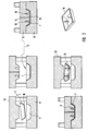
Fig. 1 zeigt in Form einer Prinzipdarstellung den verfahrensgemäßen Ablauf zur Herstellung der vorgefertigten, formstabilen Textilstruktur unter Verwendung eines Laminierwerkzeugs. In das Laminierwerkzeug 1, dessen Innenseite 2 exakt der Form und Oberflächengeometrie des fertig hergestellten Gegenstands entspricht, wird zunächst manuell oder maschinell ein textiles Flächengewebe 3, beispielsweise eine Kohlenfaserverbundstruktur, die flexibel ist, an allen Flächen des Laminierwerkzeugs bündig anliegend eingelegt. Gezeigt ist nur eine Lage, es können aber auch mehrere Lagen eingelegt werden. Die verwendete Anzahl ist bauteilabhängig. Anschließend wird der Matrixwerkstoff 4, bei dem es sich gegebenenfalls um einen zweikomponentigen Werkstoff handeln kann, zugeführt, um die Fasern des Flächengewebes in ihrer Lage zu fixieren und auf diese Weise eine formstabile Textilstruktur zu bilden, die nach dem Aushärten des Matrixwerkstoffs dem Laminierwerkzeug 1 entnommen wird. Die in der mittleren Darstellung gezeigte formstabile Textilstruktur 5 entspricht in ihrer Form exakt der Werkzeuggeometrie. Die obere Kante 6 ist die Beschnittkante, diese wird beispielsweise in einem Fräsprozess abgenommen, so dass sich die in Fig. 1 rechts gezeigte beschnittene, formstabile Textilstruktur 7 bestehend aus dem im Matrixwerkstoff fixierten textilen Flächengewebe 3 ergibt.Fig. 1 shows in the form of a schematic representation of the process according to the process for producing the prefabricated, dimensionally stable textile structure using a laminating tool. In the
Diese Textilstruktur 7 wird anschließend ebenfalls manuell oder maschinell in das Werkzeugunterteil 8 eines Spritzwerkzeugs 9 eingelegt, wobei die Werkzeugkavität 11 exakt der Form der Sichtseite oder Außenseite 10 der formstabilen Textilstruktur 7 entspricht. Dabei bildet die Anlagefläche zwischen der Textilstruktur 7 und der Dichtfläche des Werkzeugs 9 eine Sperre für das einzuspritzende Material. Entscheidend ist die optimale Passgenauigkeit der zu hinterspritzenden Textilstruktur zu der Oberfläche 11 der Kavität bei der zu erwartenden Prozesstemperatur.This
Diese Passgenauigkeit kann auf unterschiedliche Weise erstellt werden. Zum einen ist es möglich, die Spritzgusswerkzeug-Oberfläche und das Modell für das Textilstruktur-Werkzeug auf demselben Bearbeitungszentrum in einem CNC-Verfahren zu fräsen, noch bevor das Spritzgusswerkzeug zum Einsatz kommt. Somit wird sichergestellt, dass keine Bearbeitungseinflüsse von unterschiedlichen Maschinen das Ergebnis der Werkzeuganpassung verfälschen. Alternativ ist es möglich, einen Abguss des bereits einsatzfähigen Spritzgusswerkzeugs mittels Kunstharzmaterials, das eine geringe Schrumpfung besitzt, zu erstellen. Dieser Abguss wird anschließend mittels Datenrückführung in ein CAD-Modell umgewandelt und dann im CNC-Fräsprozess in ein Textilstruktur-Werkzeug kopiert. Die Textilstruktur muss dann in dem dazugehörigen Werkzeug bei derselben Prozesstemperatur hergestellt werden, bei der später spritzgegossen wird. Dies ist notwendig, da das Textilstruktur-Bauteil nur dann passgenau ist, wenn es im Werkzeug, das bei der Prozesstemperatur eine gewisse Ausdehnung hat, aushärtet und somit diese Ausdehnung "eingefroren" wird. Die im Härtungsprozess erzeugte minimale Übergröße der Schale muss exakt zu der temperaturabhängigen Übergröße des im Einsatz befindlichen Spritzgusswerkzeugs, hervorgerufen durch den Ausdehnungskoeffizienten des Werkzeugmaterials, passen, um eine optimale Abdichtwirkung zu erzielen.This fit can be created in different ways. On the one hand, it is possible to mill the injection mold surface and the model for the textile structure tool on the same machining center in a CNC process, even before the injection molding tool is used. This ensures that no machining influences of different Machines distort the result of the tool adaptation. Alternatively, it is possible to make a casting of the already operational injection molding tool by means of synthetic resin material having a low shrinkage. This casting is then converted into a CAD model by data feedback and then copied into a textile structure tool in the CNC milling process. The textile structure must then be made in the associated tool at the same process temperature that will later be injection molded. This is necessary because the textile structure component is only accurate when it cures in the tool, which has a certain extent at the process temperature, and thus this expansion is "frozen". The minimum oversize of the shell produced in the curing process must exactly match the temperature-dependent oversize of the injection molding tool in use, caused by the expansion coefficient of the tool material, in order to achieve an optimum sealing effect.
Nach dem Einlegen der Textilstruktur kann, wie hier gestrichelt dargestellt ist, eine Kupplungsschicht in Form einer tiefgezogenen Folie 12 in die schalenförmige Textilstruktur 7 eingelegt werden, die der Verbesserung der Haftung der eingespritzten Formmasse an der Textilstruktur 7 dient. Sofern auf eine Kupplungsschicht verzichtet wird, sollte die zu bespritzende Fläche der Textilstruktur 7 vor dem Einlegen in das Werkzeug 9 mechanisch aufgeraut werden, um die Oberfläche zur Verbesserung der Haftung der Formmasse zu vergrößern.After inserting the textile structure, as shown here by dashed lines, a coupling layer in the form of a deep-drawn
Nachfolgend wird das Werkzeugoberteil 13 zugefahren und verriegelt, die Form ist damit geschlossen. Am Werkzeugoberteil 13 ist der Einspritzkanal 14 für die Formmasse dargestellt, ersichtlich ist auch der Raum 15, der mit der Formmasse im Anschluss an die Textilstruktur 7 auszuspritzen ist. Gezeigt sind ferner zwei Ausnehmungen 16, die zur Ausbildung von integralen Befestigungselementen mittels der eingespritzten Formmasse dienen.Subsequently, the tool
Im nächsten Schritt wird die verflüssigte, temperierte Spritzgieß-Formmasse eingespritzt und benetzt vollständig die Textilstruktur 7 bzw. die dünne aufgelegte und infolge der Temperatur der Formmasse aufschmelzende oder erweichende Folie 12, sofern eine solche vorhanden ist. Ersichtlich füllt die Formmasse 17 auch die der Ausbildung von Befestigungselementen dienenden Räume 16 aus. Die Prozessparameter, also Spritzdruck, Spritztemperatur etc. müssen individuell an die Werkstoffe der Textilstruktur sowie die Eigenschaften der verwendeten Formmasse wie auch die Bedürfnisse des Spritzgussprozesses angepasst werden. Beim Einspritzen der Formmasse 17 erweicht die gegebenenfalls eingelegte Folie 12 und passt sich bedingt durch den Spritzdruck optimal dem jeweiligen Flächenverlauf an. Der beim Prozess vorhandene materialabhängige Einspritzdruck oder Injektionsdruck presst die Formmasse 17 gegen die Textilstruktur 7 bzw. die Folie 12 und erzeugt den nötigen Flächendruck, der zum Abdichten der Textilstruktur 7 zur Werkzeugoberfläche gegen die verflüssigte Formmasse dient. Die Formmasse kann unter Verwendung von kurzen Glasfasern, Carbonfasern oder dergleichen faserverstärkt sein.In the next step, the liquefied, tempered injection molding compound is injected and wets completely the
Nach dem Erkalten der Formmasse wird das Werkzeugoberteil 13 wieder nach oben gefahren, wonach der fertig gespritzte Gegenstand 18 entformt werden kann. Das Textilgewebe überzieht die äußere Sichtseite des Gegenstandes vollständig ohne die Optik beeinträchtigende Verwerfungen, Verziehungen etc. Anschließend wird gegebenenfalls auf die Sichtseite der Sichtlack aufgetragen, wonach diese Seite sofern erforderlich noch geschliffen und poliert wird.After cooling of the molding material, the
Fig. 3 zeigt einen Schnitt durch einen derart hergestellten Gegenstand 18. Dieser besteht ersichtlich aus der formstabilen Textilstruktur 7 mit dem eingebundenen Textilgewebe 3 und der in der Detailansicht erkennbaren Kupplungsschicht aus der Folie 12, die mit der ausgehärteten Formmasse 17 belegt ist.3 shows a section through an
Wie der Detailansicht zu entnehmen ist, wurde die Kante 19 der Textilstruktur 7 mit Formmasse 17 umspritzt, das heißt, es bildet sich im Randbereich ein Hinterschnitt 20 aus, über den ein zusätzlicher Formschluss von schalenartiger Textilstruktur und dem hinterspritzten Träger erzielt wird.As can be seen in the detail view, the
Die oben beschriebene Vorgehensweise ist lediglich exemplarisch. Wie beschrieben kann die Herstellung der Trägerstruktur 7 in anderen Verfahren erfolgen. Die verwendeten Spritzgießwerkzeuge können auch in der Ausführung der Werkzeugober- und -unterteile auch mehrteilig ausgeführt sein, sofern dies abhängig von der dreidimensionalen Oberfläche und Geometrie des Gegenstandes realisiert werden kann bzw. technisch notwendig ist. Sofern erforderlich, wird zwischen die vorgefertigte Textilstruktur und die Spritzwerkzeugfläche eine Dichtung eingelegt, um ein Umfliesen der Textilstruktur mit dem Spritzmaterial zu verhindern.The procedure described above is merely exemplary. As described, the manufacture of the
Claims (22)
Applications Claiming Priority (1)
| Application Number | Priority Date | Filing Date | Title |
|---|---|---|---|
| DE200410051334 DE102004051334A1 (en) | 2004-10-21 | 2004-10-21 | Process for producing a dimensionally stable object coated with a textile fabric, in particular a fiber composite structure |
Publications (2)
| Publication Number | Publication Date |
|---|---|
| EP1649999A2 true EP1649999A2 (en) | 2006-04-26 |
| EP1649999A3 EP1649999A3 (en) | 2007-01-03 |
Family
ID=35649832
Family Applications (1)
| Application Number | Title | Priority Date | Filing Date |
|---|---|---|---|
| EP05022660A Withdrawn EP1649999A3 (en) | 2004-10-21 | 2005-10-18 | Process for producing a form stable object with a flat textile surface, particularly with a fiber reinforced composite coating |
Country Status (2)
| Country | Link |
|---|---|
| EP (1) | EP1649999A3 (en) |
| DE (1) | DE102004051334A1 (en) |
Cited By (11)
| Publication number | Priority date | Publication date | Assignee | Title |
|---|---|---|---|---|
| WO2007093929A1 (en) * | 2006-02-13 | 2007-08-23 | Koninklijke Philips Electronics N.V. | Method of manufacturing a product part by using a composite fibre sheet and applying plastic to this sheet |
| WO2007100522A1 (en) * | 2006-02-24 | 2007-09-07 | Dow Global Technologies Inc. | Processes of forming molded parts with fabric surface areas |
| EP1977881A1 (en) * | 2007-04-05 | 2008-10-08 | Inoplast | Part of the body of an automobile, in particular a grill for a heavy goods vehicle |
| FR2981879A1 (en) * | 2011-10-27 | 2013-05-03 | Faurecia Interieur Ind | Trimming element e.g. trim panel, for trimming fascia of passenger compartment of motor vehicle, has reinforcement element impregnated by thermosetting material, where material is polymerized in contact with polymeric material of layer |
| USD703457S1 (en) | 2013-06-07 | 2014-04-29 | Herman Miller, Inc. | Chair |
| DE102012220979A1 (en) * | 2012-11-16 | 2014-05-22 | Lisa Dräxlmaier GmbH | Flexible layer with at least one regular structure made of carbon fibers useful in a component, preferably an interior part of a vehicle interior, an airbag flap or a hinge for the airbag flap |
| DE102012111350A1 (en) * | 2012-11-23 | 2014-05-28 | Webasto SE | Method for producing a planar vehicle body element and motor vehicle body element |
| EP2040352B2 (en) † | 2007-09-21 | 2014-11-19 | Grundfos Management A/S | Airgap sleeve and manufacturing method thereof |
| EP2759390A4 (en) * | 2012-05-04 | 2015-09-23 | Huawei Device Co Ltd | Carbon fibre member manufacturing method and carbon fibre member manufactured using same |
| US9211014B2 (en) | 2011-12-08 | 2015-12-15 | Herman Miller, Inc. | Composite body support member and methods for the manufacture and recycling thereof |
| EP3062984A1 (en) * | 2013-10-30 | 2016-09-07 | Compagnie Plastic Omnium | Method for producing a thermoplastic component comprising a surface reinforcing sheet |
Families Citing this family (7)
| Publication number | Priority date | Publication date | Assignee | Title |
|---|---|---|---|---|
| DE102009040901B4 (en) | 2009-09-11 | 2022-02-24 | Brose Fahrzeugteile SE & Co. Kommanditgesellschaft, Coburg | Process for manufacturing supporting structures in motor vehicles |
| DE102013106457B3 (en) * | 2013-06-20 | 2014-09-04 | Grimm-Schirp Gs Technologie Gmbh | Carbon fiber random web production process and three-dimensional nonwoven production process as well as carbon fiber random web manufacturing arrangement and nonwoven fabric |
| DE102015100925A1 (en) * | 2014-11-12 | 2016-05-12 | Hib Trim Part Solutions Gmbh | Process for the production of a trim part with a real carbon look |
| DE102014224720A1 (en) | 2014-12-03 | 2016-06-23 | Bayerische Motoren Werke Aktiengesellschaft | Method for producing a cut-formed molding with a plastic matrix and reinforcing fibers |
| EP3100915B2 (en) | 2015-06-03 | 2022-09-28 | WEIDPLAS GmbH | Component |
| DE102017213957A1 (en) * | 2017-08-10 | 2019-02-14 | Bayerische Motoren Werke Aktiengesellschaft | Method for producing a fiber-reinforced component for a motor vehicle |
| AT17163U1 (en) * | 2018-04-17 | 2021-07-15 | Andreas Kisling | Method for producing a decorative element |
Citations (5)
| Publication number | Priority date | Publication date | Assignee | Title |
|---|---|---|---|---|
| JPH10156881A (en) * | 1997-11-27 | 1998-06-16 | Mitsubishi Rayon Co Ltd | Production of carbon fiber composite molding |
| DE19931691A1 (en) * | 1999-07-08 | 2001-01-18 | Brocke Kg I B S | Plastic component molding process for producing vehicle interior cladding parts with a shatter resistant area |
| EP1219401A2 (en) * | 2000-12-29 | 2002-07-03 | Nokia Corporation | Resin injection molded article with reinforcing or decorative core |
| WO2003047857A1 (en) * | 2001-11-30 | 2003-06-12 | General Electric Company | Multilayer articles comprising resorcinol arylate polyester and method for making thereof |
| DE10227636A1 (en) * | 2002-06-21 | 2004-01-15 | Krauss-Maffei Kunststofftechnik Gmbh | Method and device for producing multi-component molded plastic parts |
Family Cites Families (11)
| Publication number | Priority date | Publication date | Assignee | Title |
|---|---|---|---|---|
| GB1067829A (en) * | 1963-11-01 | 1967-05-03 | Samuel Joseph Holtzman | Improvements in or relating to molded polypropylene articles |
| DE2009819A1 (en) * | 1970-03-03 | 1971-09-23 | Wachsmann E | Laminate for surface finishing injection moulded plastic - parts |
| DE2011954A1 (en) * | 1970-03-13 | 1971-10-21 | Wachsmann E | Laminate for surface treatment of injection mouldings |
| CH574321A5 (en) * | 1974-01-04 | 1976-04-15 | Lo Sfruttamento Di Brevetti Sa | |
| DE4417871A1 (en) * | 1994-05-21 | 1995-11-23 | Pik Partner In Kunststoff | Method and device for producing a plastic tray |
| DE19755111A1 (en) * | 1996-12-21 | 1998-06-25 | Volkswagen Ag | Moulding carbon fibre reinforced thermoplastic components with a painted finish |
| DE19960054A1 (en) * | 1999-12-13 | 2001-07-05 | Montaplast Gmbh | Making lined injection molding for vehicle internal trim, commences by preparation of textile blank with plastic film backing, followed by rear injection molding |
| DE10009304C2 (en) * | 2000-02-29 | 2002-03-21 | Montaplast Gmbh | Device for producing a plastic injection molded part provided at least on one side with a textile |
| DE10014432A1 (en) * | 2000-03-16 | 2001-09-20 | Volkswagen Ag | Coating method for molded plastic vehicle components involves roughening the surface of the molded component during the molding stage |
| DE10143883A1 (en) * | 2001-09-07 | 2003-03-27 | Magna Eybl Gmbh | Multi-layer vehicle interior panel manufacture involves molding a skin onto a prefabricated carrier layer without adhesives |
| DE10308989B4 (en) * | 2003-03-01 | 2005-12-01 | Krauss-Maffei Kunststofftechnik Gmbh | Method and device for producing a multilayer plastic molded part |
-
2004
- 2004-10-21 DE DE200410051334 patent/DE102004051334A1/en not_active Withdrawn
-
2005
- 2005-10-18 EP EP05022660A patent/EP1649999A3/en not_active Withdrawn
Patent Citations (5)
| Publication number | Priority date | Publication date | Assignee | Title |
|---|---|---|---|---|
| JPH10156881A (en) * | 1997-11-27 | 1998-06-16 | Mitsubishi Rayon Co Ltd | Production of carbon fiber composite molding |
| DE19931691A1 (en) * | 1999-07-08 | 2001-01-18 | Brocke Kg I B S | Plastic component molding process for producing vehicle interior cladding parts with a shatter resistant area |
| EP1219401A2 (en) * | 2000-12-29 | 2002-07-03 | Nokia Corporation | Resin injection molded article with reinforcing or decorative core |
| WO2003047857A1 (en) * | 2001-11-30 | 2003-06-12 | General Electric Company | Multilayer articles comprising resorcinol arylate polyester and method for making thereof |
| DE10227636A1 (en) * | 2002-06-21 | 2004-01-15 | Krauss-Maffei Kunststofftechnik Gmbh | Method and device for producing multi-component molded plastic parts |
Non-Patent Citations (3)
| Title |
|---|
| BURKLE E ET AL: "VERBUNDBAUTEILE MIT MEHRPROZESSANLAGEN WIRTSCHAFTLICH HERSTELLEN" KUNSTSTOFFE, CARL HANSER VERLAG, MUNCHEN, DE, Bd. 81, Nr. 3, 1. M{rz 1991 (1991-03-01), Seiten 192-198, XP000287480 ISSN: 0023-5563 * |
| MICHAELI W ET AL: "ENDLOSVERSTAERKTE TEILE DURCH UMSPRITZEN" PLASTVERARBEITER, HUETHIG GMBH, HEIDELBERG, DE, Bd. 49, Nr. 1, Januar 1998 (1998-01), Seiten 37-39, XP000742729 ISSN: 0032-1338 * |
| PATENT ABSTRACTS OF JAPAN Bd. 1998, Nr. 11, 30. September 1998 (1998-09-30) & JP 10 156881 A (MITSUBISHI RAYON CO LTD), 16. Juni 1998 (1998-06-16) * |
Cited By (15)
| Publication number | Priority date | Publication date | Assignee | Title |
|---|---|---|---|---|
| WO2007093929A1 (en) * | 2006-02-13 | 2007-08-23 | Koninklijke Philips Electronics N.V. | Method of manufacturing a product part by using a composite fibre sheet and applying plastic to this sheet |
| WO2007100522A1 (en) * | 2006-02-24 | 2007-09-07 | Dow Global Technologies Inc. | Processes of forming molded parts with fabric surface areas |
| EP1977881A1 (en) * | 2007-04-05 | 2008-10-08 | Inoplast | Part of the body of an automobile, in particular a grill for a heavy goods vehicle |
| FR2914579A1 (en) * | 2007-04-05 | 2008-10-10 | Inoplast Sa | BODY COMPONENT OF A MOTOR VEHICLE, ESPECIALLY CALENDER FOR HEAVY WEIGHT |
| EP2040352B2 (en) † | 2007-09-21 | 2014-11-19 | Grundfos Management A/S | Airgap sleeve and manufacturing method thereof |
| FR2981879A1 (en) * | 2011-10-27 | 2013-05-03 | Faurecia Interieur Ind | Trimming element e.g. trim panel, for trimming fascia of passenger compartment of motor vehicle, has reinforcement element impregnated by thermosetting material, where material is polymerized in contact with polymeric material of layer |
| US9211014B2 (en) | 2011-12-08 | 2015-12-15 | Herman Miller, Inc. | Composite body support member and methods for the manufacture and recycling thereof |
| EP2759390A4 (en) * | 2012-05-04 | 2015-09-23 | Huawei Device Co Ltd | Carbon fibre member manufacturing method and carbon fibre member manufactured using same |
| US9868234B2 (en) | 2012-05-04 | 2018-01-16 | Huawei Device (Dongguan) Co., Ltd. | Method for manufacturing carbon fiber component and carbon fiber component manufactured by using this method |
| DE102012220979A1 (en) * | 2012-11-16 | 2014-05-22 | Lisa Dräxlmaier GmbH | Flexible layer with at least one regular structure made of carbon fibers useful in a component, preferably an interior part of a vehicle interior, an airbag flap or a hinge for the airbag flap |
| CN104884222A (en) * | 2012-11-23 | 2015-09-02 | 韦巴斯托股份公司 | Method for producing a sheet-like motor vehicle body element and motor vehicle body element |
| DE102012111350A1 (en) * | 2012-11-23 | 2014-05-28 | Webasto SE | Method for producing a planar vehicle body element and motor vehicle body element |
| USD723851S1 (en) | 2013-06-07 | 2015-03-10 | Herman Miller, Inc. | Backrest support |
| USD703457S1 (en) | 2013-06-07 | 2014-04-29 | Herman Miller, Inc. | Chair |
| EP3062984A1 (en) * | 2013-10-30 | 2016-09-07 | Compagnie Plastic Omnium | Method for producing a thermoplastic component comprising a surface reinforcing sheet |
Also Published As
| Publication number | Publication date |
|---|---|
| DE102004051334A1 (en) | 2006-05-04 |
| EP1649999A3 (en) | 2007-01-03 |
Similar Documents
| Publication | Publication Date | Title |
|---|---|---|
| EP1649999A2 (en) | Process for producing a form stable object with a flat textile surface, particularly with a fiber reinforced composite coating | |
| DE102011102722B4 (en) | Method for in-mold decorating | |
| DE102011106151B3 (en) | Method for producing an outer module with an outer panel for a modular housing component | |
| DE102011118980B4 (en) | Method for producing an outer module with an outer panel for a modular housing component | |
| EP1727669B1 (en) | Composite part | |
| US20050255311A1 (en) | Hybrid composite product and system | |
| EP1995034A2 (en) | Moulded part, in particular decorative part and/or trim for the interior of vehicles and method for manufacturing moulded parts | |
| EP2279915A2 (en) | Multi-colour interior components | |
| DE102008009438A1 (en) | Formed part producing method, involves forming cut surface foil according to topography of formed part, applying woven fabric and resin in cutting tool on inside of foil, and taking out finished part after precipitation hardening to tool | |
| DE10143883A1 (en) | Multi-layer vehicle interior panel manufacture involves molding a skin onto a prefabricated carrier layer without adhesives | |
| DE102015208946A1 (en) | Plastic component and method for producing a plastic component | |
| DE102009016177A1 (en) | Composite construction part i.e. interior cladding element, for motor vehicle, has double layer part comprising decoration layer and base layer, where functional layer is provided below double layer part | |
| DE102013205185A1 (en) | In-Mold scarskin lining for interior panel with decoration application | |
| EP1955840B1 (en) | Method for manufacturing a moulded product | |
| WO2008113446A1 (en) | Component, in particular interior trim part for a motor vehicle, and method of production | |
| EP1235679B1 (en) | Method for producing components of interior fittings in motor vehicles and corresponding article | |
| EP0410553A2 (en) | Method for the production of lined and formed articles | |
| DE102012014082B4 (en) | Decorative molding and process for its manufacture | |
| DE102005003713A1 (en) | Fiber reinforced sandwich structure with hollow core made by vacuum-assisted impregnation, e.g. for aircraft use, includes a separation layer to control resin penetration | |
| EP3112127B1 (en) | Method for producing a panelling component | |
| EP2540471A2 (en) | Method for manufacturing moulds and mould | |
| DE102005039600A1 (en) | Grain finish vehicle interior panel manufacture involves injecting plastic onto rear of plain film in molding tool with negative grain surface to form supporting layer with decorative grained surface | |
| DE102015208945A1 (en) | IMD plastic component and method of making an IMD plastic component | |
| DE102004014682B4 (en) | Method for producing a composite body serving as at least partial cladding of, in particular, sound generators and use thereof | |
| EP2457706A2 (en) | Device and method for producing flat laminated components |
Legal Events
| Date | Code | Title | Description |
|---|---|---|---|
| PUAI | Public reference made under article 153(3) epc to a published international application that has entered the european phase |
Free format text: ORIGINAL CODE: 0009012 |
|
| AK | Designated contracting states |
Kind code of ref document: A2 Designated state(s): AT BE BG CH CY CZ DE DK EE ES FI FR GB GR HU IE IS IT LI LT LU LV MC NL PL PT RO SE SI SK TR |
|
| AX | Request for extension of the european patent |
Extension state: AL BA HR MK YU |
|
| PUAL | Search report despatched |
Free format text: ORIGINAL CODE: 0009013 |
|
| AK | Designated contracting states |
Kind code of ref document: A3 Designated state(s): AT BE BG CH CY CZ DE DK EE ES FI FR GB GR HU IE IS IT LI LT LU LV MC NL PL PT RO SE SI SK TR |
|
| AX | Request for extension of the european patent |
Extension state: AL BA HR MK YU |
|
| AKX | Designation fees paid | ||
| STAA | Information on the status of an ep patent application or granted ep patent |
Free format text: STATUS: THE APPLICATION IS DEEMED TO BE WITHDRAWN |
|
| 18D | Application deemed to be withdrawn |
Effective date: 20070704 |
|
| REG | Reference to a national code |
Ref country code: DE Ref legal event code: 8566 |