EP1650046A1 - Donor substrate and fabrication method for organic light emitting display using the same - Google Patents
Donor substrate and fabrication method for organic light emitting display using the same Download PDFInfo
- Publication number
- EP1650046A1 EP1650046A1 EP20050109540 EP05109540A EP1650046A1 EP 1650046 A1 EP1650046 A1 EP 1650046A1 EP 20050109540 EP20050109540 EP 20050109540 EP 05109540 A EP05109540 A EP 05109540A EP 1650046 A1 EP1650046 A1 EP 1650046A1
- Authority
- EP
- European Patent Office
- Prior art keywords
- layer
- light
- heat
- donor substrate
- heat generation
- Prior art date
- Legal status (The legal status is an assumption and is not a legal conclusion. Google has not performed a legal analysis and makes no representation as to the accuracy of the status listed.)
- Granted
Links
- 239000000758 substrate Substances 0.000 title claims abstract description 195
- 238000000034 method Methods 0.000 title claims abstract description 26
- 238000004519 manufacturing process Methods 0.000 title claims abstract description 21
- 238000006243 chemical reaction Methods 0.000 claims abstract description 121
- 230000020169 heat generation Effects 0.000 claims abstract description 64
- 230000001678 irradiating effect Effects 0.000 claims abstract description 4
- 239000010410 layer Substances 0.000 claims description 337
- 239000012044 organic layer Substances 0.000 claims description 11
- 238000002347 injection Methods 0.000 claims description 4
- 239000007924 injection Substances 0.000 claims description 4
- 230000005525 hole transport Effects 0.000 claims description 2
- 230000000903 blocking effect Effects 0.000 claims 1
- 239000010408 film Substances 0.000 description 9
- 239000011229 interlayer Substances 0.000 description 7
- 239000004065 semiconductor Substances 0.000 description 7
- 239000000853 adhesive Substances 0.000 description 5
- 230000001070 adhesive effect Effects 0.000 description 5
- 239000011358 absorbing material Substances 0.000 description 3
- 230000015572 biosynthetic process Effects 0.000 description 3
- 239000006229 carbon black Substances 0.000 description 3
- 229910044991 metal oxide Inorganic materials 0.000 description 3
- 150000004706 metal oxides Chemical class 0.000 description 3
- 239000010409 thin film Substances 0.000 description 3
- 229910001316 Ag alloy Inorganic materials 0.000 description 2
- 229910000838 Al alloy Inorganic materials 0.000 description 2
- BQCADISMDOOEFD-UHFFFAOYSA-N Silver Chemical compound [Ag] BQCADISMDOOEFD-UHFFFAOYSA-N 0.000 description 2
- 229910052782 aluminium Inorganic materials 0.000 description 2
- XAGFODPZIPBFFR-UHFFFAOYSA-N aluminium Chemical compound [Al] XAGFODPZIPBFFR-UHFFFAOYSA-N 0.000 description 2
- 229910021417 amorphous silicon Inorganic materials 0.000 description 2
- 239000011230 binding agent Substances 0.000 description 2
- 238000003384 imaging method Methods 0.000 description 2
- 229910052751 metal Inorganic materials 0.000 description 2
- 239000002184 metal Substances 0.000 description 2
- 229910052976 metal sulfide Inorganic materials 0.000 description 2
- 229910052709 silver Inorganic materials 0.000 description 2
- 239000004332 silver Substances 0.000 description 2
- 239000004925 Acrylic resin Substances 0.000 description 1
- 229920000178 Acrylic resin Polymers 0.000 description 1
- OKTJSMMVPCPJKN-UHFFFAOYSA-N Carbon Chemical compound [C] OKTJSMMVPCPJKN-UHFFFAOYSA-N 0.000 description 1
- 238000007754 air knife coating Methods 0.000 description 1
- 229920000180 alkyd Polymers 0.000 description 1
- 238000000576 coating method Methods 0.000 description 1
- 150000001875 compounds Chemical class 0.000 description 1
- 238000000151 deposition Methods 0.000 description 1
- 238000000313 electron-beam-induced deposition Methods 0.000 description 1
- 238000005516 engineering process Methods 0.000 description 1
- 229910002804 graphite Inorganic materials 0.000 description 1
- 239000010439 graphite Substances 0.000 description 1
- AMGQUBHHOARCQH-UHFFFAOYSA-N indium;oxotin Chemical compound [In].[Sn]=O AMGQUBHHOARCQH-UHFFFAOYSA-N 0.000 description 1
- 239000000463 material Substances 0.000 description 1
- 238000012986 modification Methods 0.000 description 1
- 230000004048 modification Effects 0.000 description 1
- 239000002120 nanofilm Substances 0.000 description 1
- 238000002161 passivation Methods 0.000 description 1
- 230000035699 permeability Effects 0.000 description 1
- 229910021420 polycrystalline silicon Inorganic materials 0.000 description 1
- 229920006267 polyester film Polymers 0.000 description 1
- 229920006290 polyethylene naphthalate film Polymers 0.000 description 1
- -1 polyethylene terephthalate Polymers 0.000 description 1
- 229920000139 polyethylene terephthalate Polymers 0.000 description 1
- 239000005020 polyethylene terephthalate Substances 0.000 description 1
- 229920005591 polysilicon Polymers 0.000 description 1
- 238000007650 screen-printing Methods 0.000 description 1
- 238000004544 sputter deposition Methods 0.000 description 1
- 238000001771 vacuum deposition Methods 0.000 description 1
- YVTHLONGBIQYBO-UHFFFAOYSA-N zinc indium(3+) oxygen(2-) Chemical compound [O--].[Zn++].[In+3] YVTHLONGBIQYBO-UHFFFAOYSA-N 0.000 description 1
Images


Classifications
-
- H—ELECTRICITY
- H05—ELECTRIC TECHNIQUES NOT OTHERWISE PROVIDED FOR
- H05B—ELECTRIC HEATING; ELECTRIC LIGHT SOURCES NOT OTHERWISE PROVIDED FOR; CIRCUIT ARRANGEMENTS FOR ELECTRIC LIGHT SOURCES, IN GENERAL
- H05B33/00—Electroluminescent light sources
- H05B33/10—Apparatus or processes specially adapted to the manufacture of electroluminescent light sources
-
- B—PERFORMING OPERATIONS; TRANSPORTING
- B41—PRINTING; LINING MACHINES; TYPEWRITERS; STAMPS
- B41M—PRINTING, DUPLICATING, MARKING, OR COPYING PROCESSES; COLOUR PRINTING
- B41M5/00—Duplicating or marking methods; Sheet materials for use therein
- B41M5/26—Thermography ; Marking by high energetic means, e.g. laser otherwise than by burning, and characterised by the material used
- B41M5/40—Thermography ; Marking by high energetic means, e.g. laser otherwise than by burning, and characterised by the material used characterised by the base backcoat, intermediate, or covering layers, e.g. for thermal transfer dye-donor or dye-receiver sheets; Heat, radiation filtering or absorbing means or layers; combined with other image registration layers or compositions; Special originals for reproduction by thermography
- B41M5/46—Thermography ; Marking by high energetic means, e.g. laser otherwise than by burning, and characterised by the material used characterised by the base backcoat, intermediate, or covering layers, e.g. for thermal transfer dye-donor or dye-receiver sheets; Heat, radiation filtering or absorbing means or layers; combined with other image registration layers or compositions; Special originals for reproduction by thermography characterised by the light-to-heat converting means; characterised by the heat or radiation filtering or absorbing means or layers
-
- B—PERFORMING OPERATIONS; TRANSPORTING
- B41—PRINTING; LINING MACHINES; TYPEWRITERS; STAMPS
- B41M—PRINTING, DUPLICATING, MARKING, OR COPYING PROCESSES; COLOUR PRINTING
- B41M5/00—Duplicating or marking methods; Sheet materials for use therein
- B41M5/26—Thermography ; Marking by high energetic means, e.g. laser otherwise than by burning, and characterised by the material used
- B41M5/265—Thermography ; Marking by high energetic means, e.g. laser otherwise than by burning, and characterised by the material used for the production of optical filters or electrical components
-
- C—CHEMISTRY; METALLURGY
- C23—COATING METALLIC MATERIAL; COATING MATERIAL WITH METALLIC MATERIAL; CHEMICAL SURFACE TREATMENT; DIFFUSION TREATMENT OF METALLIC MATERIAL; COATING BY VACUUM EVAPORATION, BY SPUTTERING, BY ION IMPLANTATION OR BY CHEMICAL VAPOUR DEPOSITION, IN GENERAL; INHIBITING CORROSION OF METALLIC MATERIAL OR INCRUSTATION IN GENERAL
- C23C—COATING METALLIC MATERIAL; COATING MATERIAL WITH METALLIC MATERIAL; SURFACE TREATMENT OF METALLIC MATERIAL BY DIFFUSION INTO THE SURFACE, BY CHEMICAL CONVERSION OR SUBSTITUTION; COATING BY VACUUM EVAPORATION, BY SPUTTERING, BY ION IMPLANTATION OR BY CHEMICAL VAPOUR DEPOSITION, IN GENERAL
- C23C14/00—Coating by vacuum evaporation, by sputtering or by ion implantation of the coating forming material
- C23C14/04—Coating on selected surface areas, e.g. using masks
- C23C14/048—Coating on selected surface areas, e.g. using masks using irradiation by energy or particles
-
- H—ELECTRICITY
- H10—SEMICONDUCTOR DEVICES; ELECTRIC SOLID-STATE DEVICES NOT OTHERWISE PROVIDED FOR
- H10K—ORGANIC ELECTRIC SOLID-STATE DEVICES
- H10K71/00—Manufacture or treatment specially adapted for the organic devices covered by this subclass
- H10K71/10—Deposition of organic active material
- H10K71/18—Deposition of organic active material using non-liquid printing techniques, e.g. thermal transfer printing from a donor sheet
-
- H—ELECTRICITY
- H10—SEMICONDUCTOR DEVICES; ELECTRIC SOLID-STATE DEVICES NOT OTHERWISE PROVIDED FOR
- H10K—ORGANIC ELECTRIC SOLID-STATE DEVICES
- H10K71/00—Manufacture or treatment specially adapted for the organic devices covered by this subclass
-
- H—ELECTRICITY
- H10—SEMICONDUCTOR DEVICES; ELECTRIC SOLID-STATE DEVICES NOT OTHERWISE PROVIDED FOR
- H10K—ORGANIC ELECTRIC SOLID-STATE DEVICES
- H10K71/00—Manufacture or treatment specially adapted for the organic devices covered by this subclass
- H10K71/40—Thermal treatment, e.g. annealing in the presence of a solvent vapour
- H10K71/421—Thermal treatment, e.g. annealing in the presence of a solvent vapour using coherent electromagnetic radiation, e.g. laser annealing
-
- Y—GENERAL TAGGING OF NEW TECHNOLOGICAL DEVELOPMENTS; GENERAL TAGGING OF CROSS-SECTIONAL TECHNOLOGIES SPANNING OVER SEVERAL SECTIONS OF THE IPC; TECHNICAL SUBJECTS COVERED BY FORMER USPC CROSS-REFERENCE ART COLLECTIONS [XRACs] AND DIGESTS
- Y10—TECHNICAL SUBJECTS COVERED BY FORMER USPC
- Y10S—TECHNICAL SUBJECTS COVERED BY FORMER USPC CROSS-REFERENCE ART COLLECTIONS [XRACs] AND DIGESTS
- Y10S430/00—Radiation imagery chemistry: process, composition, or product thereof
- Y10S430/146—Laser beam
Definitions
- the present invention relates to a donor substrate and, more particularly, to a donor substrate for laser thermal transfer, and to a fabrication method of an organic light emitting display using the donor substrate.
- the donor film comprises a base film, a light-to-heat conversion layer disposed on the entire surface of the base film, and a transfer layer disposed on the entire surface of the light-to-heat conversion layer.
- the donor film is laminated on the acceptor substrate so that the transfer layer faces the acceptor substrate.
- a laser beam is irradiated onto the donor film. Accordingly, transfer layer patterns are formed on the acceptor substrate.
- transfer layer patterns on the acceptor substrate by irradiating the laser beam onto the base film is now described in detail.
- the laser beam is irradiated onto parts of the base film.
- the light-to-heat conversion layer in the areas onto which the laser beam is irradiated absorbs the laser beam, and converts the laser beam to thermal energy.
- the transfer layer contacting the regions of the light-to-heat conversion layer, from which the thermal energy is generated is transferred to the acceptor substrate selectively by the thermal energy, thereby forming transfer layer patterns.
- the width of the transfer layer pattern corresponds to the width of the laser beam. Therefore, if it is intended to minutely form the transfer layer pattern, the width of the laser beam should be adjusted with accuracy.
- the accurate adjustment of the width of the laser beam requires a highly accurate laser apparatus. Such a laser apparatus with high accuracy comes at a high price, thereby causing an increase in the fabrication cost of an organic light emitting display.
- the present invention provides a donor substrate which permits accurate formation of a minute transfer layer pattern without requiring accurate control of the width of a laser beam.
- the present invention also provides a fabrication method of an organic light emitting display, which method permits the accurate formation of a minute transfer layer pattern using the donor substrate.
- a donor substrate includes a base substrate and a transfer layer disposed on the base substrate.
- a selective heat generation structure is interposed between the base substrate and the transfer layer.
- the selective heat generation structure has a heat generation region from which heat is generated by light-to-heat conversion, and a heat non-generation region contacting the heat generation region.
- a donor substrate comprises: a base substrate and a light-to-heat conversion (LTHC) layer pattern selectively disposed on a part of the base substrate and a transfer layer is disposed on the light-to-heat conversion layer pattern.
- the donor substrate further comprises a reflective layer disposed on a part of the base substrate not covered by the light-to-heat conversion layer pattern.
- the reflective layer covers the light-to-heat conversion layer pattern.
- the donor substrate further comprises an intermediate layer interposed between the light-to-heat conversion layer pattern and the transfer layer.
- the donor substrate further comprises a reflective layer covering the light-to-heat conversion layer pattern; and an intermediate layer interposed between the reflective layer and the transfer layer.
- the base substrate has a recessed region, and wherein the light-to-heat conversion layer pattern is selectively disposed in the recessed region.
- the donor substrate further comprises a reflective layer interposed between the transfer layer and both of the light-to-heat conversion layer pattern and the base substrate.
- the donor substrate further comprises an intermediate layer interposed between the transfer layer and both of the light-to-heat conversion layer pattern and the base substrate.
- the donor substrate further comprises a reflective layer disposed on the light-to-heat conversion layer pattern and the base substrate; and an intermediate layer interposed between the reflective layer and the transfer layer.
- a donor substrate comprises a base substrate, and a reflective layer pattern is selectively disposed on a part of the base substrate, wherein the reflective layer pattern is covered with a light-to-heat conversion layer and a transfer layer is disposed on the light-to-heat conversion layer.
- the donor substrate further comprises a reflective layer interposed between the light-to-heat conversion layer and the transfer layer.
- the donor substrate further comprises an intermediate layer interposed between the light-to-heat conversion layer and the transfer layer.
- the donor substrate preferably further comprises a reflective layer disposed on the light-to-heat conversion layer; and an intermediate layer interposed between the reflective layer and the transfer layer.
- the donor substrate described above is first prepared. Then, the donor substrate is disposed on an acceptor substrate having at least a pixel electrode so that the transfer layer of the donor substrate faces the acceptor substrate. A transfer layer pattern is then formed on the pixel electrode of the acceptor substrate by irradiating a laser beam, having a width greater than that of the heat generation region, onto the donor substrate.
- FIG. 1 is a plan view of a donor substrate according to two embodiments of the present invention.
- FIG. 2A is a cross-sectional view taken along Line I-I' of FIG. 1, and shows a donor substrate according to a first embodiment of the present invention
- FIG. 2B is a cross-sectional view illustrating a fabrication method of an organic light emitting display using the donor substrate shown in FIG. 2A;
- FIG. 3A is a cross-sectional view taken along Line I-I' of FIG. 1, and shows a donor substrate according to a second embodiment of the present invention
- FIG. 3B is a cross-sectional view illustrating a fabrication method of an organic light emitting display using the donor substrate shown in FIG. 3A;
- FIG. 4 is a plan view of a donor substrate according to another embodiment of the present invention.
- FIG. 5A is a cross-sectional view taken along Line I-I' of FIG. 4, and shows a donor substrate according to a third embodiment of the present invention
- FIG. 5B is a cross-sectional view illustrating a fabrication method of an organic light emitting display using the donor substrate shown in FIG. 5A;
- FIG. 6 is an enlarged cross-sectional view of a part of FIGS. 2B, 3B, and 5B.
- FIG. 1 is a plan view of a donor substrate according to two embodiments of the present invention.
- a donor substrate D1 or D2 comprises a base substrate 10 or 20.
- Light-to-heat conversion layer patterns 13 or 23 are disposed on parts of the base substrate 10 or 20.
- the light-to-heat conversion layer patterns 13 or 23 define heat generation regions.
- the donor substrate D1 or D2 may be used to form an emission layer of an organic light emitting display.
- the light-to-heat conversion layer patterns 13 or 23 correspond to respective unit pixel regions of the organic light emitting display.
- the organic light emitting display displays a full color image of red, green and blue, a red emission layer, a green emission layer and a blue emission layer are patterned, respectively.
- three sheets of donor substrates are required, and the three sheets of donor substrates can include first light-to-heat conversion layer patterns 13 or 23, second light-to-heat conversion layer patterns 13' or 23', and third light-to-heat conversion layer patterns 13" or 23" different in position from each other, respectively.
- a donor substrate D1 or D2 for forming striped emission layer patterns is shown, but the present invention is not limited to that. Instead, the present invention may be applied to a donor substrate for forming dotted or delta emission layer patterns. Furthermore, the present invention may be applied to a donor substrate for forming a variety of different patterns on an acceptor substrate.
- FIG. 2A is a cross-sectional view taken along Line I-I' of FIG. 1, and shows a donor substrate according to a first embodiment of the present invention.
- the donor substrate D1 comprises a base substrate 10.
- the base substrate 10 has a high permeability for a laser beam, high thermal resistance, and proper flexibility and mechanical strength. Therefore, the base substrate 10 may be made of a polyester film.
- the base substrate 10 may be made of a polyethylene terephthalate film or a polyethylene naphthalate film.
- the thickness of the base substrate 10 preferably ranges from 10 mm to 500 ⁇ m.
- a transfer layer 19 is disposed on the base substrate 10.
- the transfer layer 19 is disposed on the entire top surface of the base substrate 10.
- the transfer layer 19 may be an electroluminescent organic layer, in other words, an emission layer.
- the transfer layer 19 may further comprise at least one layer selected from a group consisting of a hole-injecting organic layer, a hole-transporting organic layer, a hole-blocking organic layer, an electron-transporting organic layer, and an electron-injecting organic layer.
- a selective heat generation structure S1 is interposed between the base substrate 10 and the transfer layer 19.
- the selective heat generation structure S1 comprises a heat generation region from which heat is generated by light-to-heat conversion, and a heat non-generation region adjacent to the heat generation region.
- the heat non-generation region is not a region from which heat is not generated absolutely. Rather, "heat non-generation” should be understood as a relative concept with respect to "heat generation”.
- the selective heat generation structure S1 comprises light-to-heat conversion (LTHC) layer patterns 13 selectively disposed on parts of the base substrate 10.
- the light-to-heat conversion layer pattern 13 defines the heat generation region.
- the light-to-heat conversion layer pattern 13 absorbs a part of a laser beam, and converts the absorbed laser beam into heat. Therefore, heat can be selectively generated from the light-to-heat conversion layer patterns 13.
- the transfer layer 19 contacting the light-to-heat conversion layer patterns 13 is degraded in adhesive power due to the heat. Accordingly, the transfer layer 19 is selectively transferred to an acceptor substrate, thereby forming transfer layer patterns. As a result, it is possible to form minute transfer layer patterns regardless of the width of the laser beam.
- the light-to-heat conversion layer pattern 13 contains a light-absorbing material.
- the light-absorbing material include carbon black, graphite, metal oxide, and metal sulfide.
- the light-to-heat conversion layer pattern 13 may further contain a binder.
- Suitable examples of the light-to-heat conversion layer pattern 13 include an organic layer in which carbon black is dispersed in an organic binder, and a metal layer containing metal oxide or metal sulfide.
- the light-to-heat conversion layer pattern 13 is an organic layer, the light-to-heat conversion layer pattern 13 can be formed using a screen printing method.
- the light-to-heat conversion layer pattern 13 when the light-to-heat conversion layer pattern 13 is a metal layer, the light-to-heat conversion layer pattern 13 can be formed using a vacuum deposition method, an electron beam deposition method, or a sputtering method, which employ a highly accurate mask.
- the selective heat generation structure S1 may further comprise a reflective layer 15 disposed on those portions of the base substrate 10 not covered by the light-to-heat conversion layer pattern 13.
- the reflective layer 15 is a layer having a proper reflectance for a laser beam, and reflects the laser beam input through the base substrate 10. Therefore, the reflective layer 15 can define the heat non-generation region.
- the reflective layer 15 may be at least one layer selected from a group consisting of an aluminum layer, an aluminum alloy layer, a silver layer, and a silver alloy layer.
- the reflective layer 15 cover the light-to-heat conversion layer pattern 13.
- the region 15a of the reflective layer 15 which is positioned on the light-to-heat conversion layer pattern 13 reflects the laser beam passing through the light-to-heat conversion layer pattern 13, and returns the laser beam into the light-to-heat conversion layer pattern 13. Accordingly, the light-to-heat conversion rate in the light-to-heat conversion layer pattern 13 can be enhanced.
- An intermediate layer 17 can be interposed between the selective heat generation structure S1 including the reflective layer 15 and the transfer layer 19.
- the intermediate layer 17 serves to prevent the light-absorbing material (for example, carbon black) contained in the light-to-heat conversion layer pattern 13 from contaminating the transfer layer 19, and also serves to block gas generated when the light-to-heat conversion layer pattern 13 converts the laser beam into heat.
- the intermediate layer 17 be made of a material having high thermal resistance, and that it have adhesive power relative to the transfer layer 19.
- the intermediate layer 17 may be an organic layer, an inorganic layer, or a compound layer thereof.
- the organic layer may be a high-molecular film made of acrylic resin or alkyd resin, and the inorganic layer may be a metal oxide layer.
- the reflective layer 15 may be omitted.
- the intermediate layer 17 is interposed between the light-to-heat conversion layer pattern 13 and the transfer layer 19, that is, between the transfer layer 19 and the selective heat generation structure S1 not including the reflective layer 15. Specifically, the intermediate layer 17 covers the light-to-heat conversion layer pattern 13.
- FIG. 2B is a cross-sectional view illustrating a fabrication method of an organic light emitting display using the donor substrate shown in FIG. 2A.
- the donor substrate D1 described with reference to FIG. 2A is disposed on an acceptor substrate A1 having at least a pixel electrode so that the transfer layer 19 faces the acceptor substrate A1.
- a laser beam is irradiated onto the donor substrate D1.
- the laser beam may be a beam patterned in a line beam shape.
- the patterned laser beam is irradiated onto the heat generation region of the donor substrate D1.
- the width W1 of the laser beam is greater than the width Wc of the heat generation region.
- the laser beam L11 irradiated onto the donor substrate D1 is transmitted by the base substrate 10 and is partially absorbed by the light-to-heat conversion layer pattern 13. Moreover, when the reflective layer 15 covering the light-to-heat conversion layer pattern 13 is provided, the laser beam L12 not absorbed but transmitted by the light-to-heat conversion layer pattern 13 is reflected by the reflective layer 15a on the light-to-heat conversion layer pattern 13, and is returned into the light-to-heat conversion layer pattern 13. Accordingly, the light-to-heat conversion rate in the light-to-heat conversion layer pattern 13 can be enhanced.
- the laser beam L13 irradiated onto the reflective layer 15 adjacent to the sides of the light-to-heat conversion layer pattern 13 is reflected by the reflective layer 15.
- the reflective layer 15 is not provided, the laser beam passes through the sides of the light-to-heat conversion layer pattern 13. As a result, heat can be selectively generated from the region in which the light-to-heat conversion layer pattern 13 is formed.
- the heat generated from the light-to-heat conversion layer pattern 13 degrades adhesive power between the intermediate layer 17 and the transfer layer 19, thereby selectively transferring the transfer layer 19 onto the acceptor substrate A1. Consequently, it is possible to form a transfer layer pattern 19a on the acceptor substrate A1.
- the width W1 of the laser beam can be greater than the width Wt of the transfer layer pattern patterned on the acceptor substrate A1. Therefore, it is possible to obtain a minute transfer layer pattern without accurately controlling the width W1 of the laser beam.
- FIG. 3A is a cross-sectional view taken along Line I-I' of FIG. 1, and shows a donor substrate according to a second embodiment of the present invention.
- the donor substrate according to the present embodiment is similar to the donor substrate described with reference to FIG. 2A, except as described below.
- a donor substrate D2 comprises a base substrate 20 and a transfer layer 29 disposed on the base substrate 20.
- a selective heat generation structure S2 is interposed between the base substrate 20 and the transfer layer 29.
- the selective heat generation structure S2 comprises a heat generation region from which heat is generated by light-to-heat conversion, and a heat non-generation region adjacent to the heat generation region.
- the selective heat generation structure S2 comprises light-to-heat conversion (LTHC) layer patterns 23 selectively disposed on parts of the base substrate 20.
- the base substrate 20 has recessed regions 20a, and the light-to-heat conversion layer patterns 23 are selectively disposed in the recessed regions 20a.
- the light-to-heat conversion layer patterns 23 selectively disposed in the recessed regions 20a define the heat generation regions.
- the base substrate 20 having the recessed regions 20a can be manufactured using, for example, a mold.
- the light-to-heat conversion layer patterns 23 can be selectively formed in the recessed regions 20a using an air knife coating method or a blade coating method.
- the selective heat generation structure S2 may further comprise a reflective layer 25 interposed between the transfer layer 29 and both the light-to-heat conversion layer patterns 23 and the base substrate 20.
- the reflective layer 25 reflects the laser beam inputted through the base substrate 20.
- the reflective layer 25 can define the heat non-generation region.
- An intermediate layer 27 can be interposed between the selective heat generation structure S2 including the reflective layer 25 and the transfer layer 29.
- the reflective layer 25 may be omitted.
- the intermediate layer 27 can be interposed between the transfer layer 19 and both the light-to-heat conversion layer patterns 23 and the base substrate 20.
- FIG. 3B is a cross-sectional view illustrating a fabrication method of an organic light emitting display using the donor substrate shown in FIG. 3A.
- the donor substrate D2 described with reference to FIG. 3A is disposed on an acceptor substrate A2 so that the transfer layer 29 faces the acceptor substrate A2. Subsequently, a laser beam is irradiated onto the donor substrate D2.
- the laser beam may be a beam patterned in a line beam shape.
- the patterned laser beam is irradiated onto the heat generation regions of the donor substrate D2.
- the width W1 of each laser beam is greater than the width Wc of each heat generation region.
- the laser beam L21 irradiated onto the donor substrate D2 is partially absorbed by the light-to-heat conversion layer pattern 23.
- the reflective layer 25 is provided on the light-to-heat conversion layer pattern 23
- the laser beam L22 not absorbed but transmitted by the light-to-heat conversion layer pattern 23 is reflected by the reflective layer 25a on the light-to-heat conversion layer pattern 23, and is returned into the light-to-heat conversion layer pattern 23. Accordingly, the light-to-heat conversion rate in the light-to-heat conversion layer pattern 23 can be enhanced.
- the laser beam L23 irradiated onto the region 25b of the reflective layer 25 adjacent to the sides of the light-to-heat conversion layer pattern 23 is reflected by the reflective layer 25.
- the reflective layer 25 is not provided, the laser beam passes through the sides of the light-to-heat conversion layer pattern 23. As a result, heat can be selectively generated from the region in which the light-to-heat conversion layer pattern 23 is formed.
- the heat generated from the light-to-heat conversion layer pattern 23 degrades the adhesive power between the intermediate layer 27 and the transfer layer 29, thereby selectively transferring the transfer layer 29 onto the acceptor substrate A2. Consequently, it is possible to form a transfer layer pattern 29a on the acceptor substrate A2.
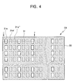
- FIG. 4 is a plan view of a donor substrate according to another embodiment of the present invention.
- a donor substrate D3 comprises a base substrate 30.
- Reflective layer patterns 31 are disposed on parts of the base substrate 30.
- Each reflective layer pattern 31 defines a heat non-generation region.
- a light-to-heat conversion layer is disposed on regions 31a of the base substrate 30 exposed to the sides of the reflective layer pattern 31. That is, the exposed region 31a can define a heat generation region.
- the donor substrate D3 may be used to form an emission layer of an organic light emitting display.
- the exposed regions 31a in which the light-to-heat conversion layer is exposed, correspond to respective unit pixel regions of the organic light emitting display.
- the three sheets of donor substrates can include reflective layer patterns having first exposed regions 31a, second exposed regions 31a', and third exposed regions 31a" different in position from each other, respectively.
- a donor substrate D3 for forming striped emission layer patterns is shown, but the present invention is not limited to that. Instead, the present invention may be applied to a donor substrate for forming dotted or delta emission layer patterns. Furthermore, the present invention may be applied to a donor substrate for forming a variety of different patterns on an acceptor substrate.
- FIG. 5A is a cross-sectional view taken along Line I-I' of FIG. 4, and shows a donor substrate according to a third embodiment of the present invention.
- the donor substrate according to the present embodiment is similar to the donor substrate described with reference to FIG. 2A, except as described below.
- the donor substrate D3 comprises a base substrate 30 and a transfer layer 39 disposed on the base substrate 30.
- a selective heat generation structure S3 is interposed between the base substrate 30 and the transfer layer 39.
- the selective heat generation structure S3 comprises a heat generation region from which heat is generated by light-to-heat conversion, and a heat non-generation region contacting the heat generation region.
- the selective heat generation structure S3 comprises reflective layer patterns 31 selectively disposed on parts of the base substrate 30, and light-to-heat conversion layer pattern 33 covering the reflective layer patterns 31.
- the light-to-heat conversion layer 33 is disposed on the reflective layer patterns 31 and the area 31a of the base substrate 30 not covered by the reflective layer patterns 31.
- the reflective layer patterns 31 reflect a part of a laser beam inputted through the base substrate 30, thereby defining the heat non-generation region.
- the reflective layer pattern 31 has a proper reflectance for a laser beam, and may be at least one layer selected from a group consisting of an aluminum layer, an aluminum alloy layer, a silver layer, and a silver alloy layer.
- the reflective layer pattern 31 can be formed on the base substrate 30 using a deposition method, which employs a highly accurate mask.
- the selective heat generation structure S3 may further comprise a reflective layer 35 disposed on the light-to-heat conversion layer 33.
- the reflective layer 35 reflects the laser beam passing through the light-to-heat conversion layer 33, and returns the laser beam into the light-to-heat conversion layer 33.
- the light-to-heat conversion rate in the light-to-heat conversion layer 33 can be enhanced.
- An intermediate layer 37 can be interposed between the selective heat generation structure S3 including the reflective layer 35 and the transfer layer 39.
- the reflective layer 35 may be omitted.
- the intermediate layer 37 can be interposed between the light-to-heat conversion layer 33 and the transfer layer 39.
- FIG. 5B is a cross-sectional view illustrating a fabrication method of an organic light emitting display using the donor substrate shown in FIG. 5A.
- the donor substrate D3 described with reference to FIG. 5A is disposed on an acceptor substrate A3 so that the transfer layer 39 faces the acceptor substrate A3. Subsequently, a laser beam is irradiated onto the donor substrate D3.
- the laser beam may be a beam patterned in a line beam shape.
- the patterned laser beam is irradiated onto the heat generation region of the donor substrate D3.
- the width W1 of the laser beam is greater than the width Wc of the heat generation region.
- the laser beam L31 irradiated onto the donor substrate D3 is transmitted by the base substrate 30, and is partially absorbed by the light-to-heat conversion layer 33.
- the reflective layer 35 is provided on the light-to-heat conversion layer 33
- the laser beam L32 not absorbed but transmitted by the light-to-heat conversion layer 33 is reflected by the reflective layer 35, and is returned into the light-to-heat conversion layer 33. Accordingly, the light-to-heat conversion rate in the light-to-heat conversion layer 33 can be enhanced.
- the laser beam L33 irradiated onto the reflective layer pattern 31 is reflected by the reflective layer pattern 31. As a result, heat can be selectively generated from the region of the light-to-heat conversion layer 33 contacting the exposed base substrate 30.
- the heat generated from the light-to-heat conversion layer 33 degrades the adhesive power between the intermediate layer 37 and the transfer layer 39, thereby selectively transferring the transfer layer 39 onto the acceptor substrate A3. Consequently, it is possible to form the transfer layer pattern 39a on the acceptor substrate A3.
- FIG. 6 is an enlarged cross-sectional view of a part of FIGS. 2B, 3B, and 5B. It shows a case wherein the acceptor substrates A1, A2, and A3 are organic light emitting device substrates.
- a semiconductor layer 120 is disposed in a predetermined region.
- the semiconductor layer 120 may be made of an amorphous silicon layer or a poly silicon layer obtained by crystallizing an amorphous silicon layer.
- a gate insulating layer 125 is disposed on the semiconductor layer 120.
- a gate electrode 130 overlying the semiconductor layer 120 is disposed on the gate insulating layer 125.
- a first insulating interlayer 135 covering the semiconductor layer 120 and the gate electrode 130 is disposed on the gate electrode 130.
- a drain electrode 141 and a source electrode 143 which pass through the first insulating interlayer 135 and the gate insulating layer 125, and which are connected to respective ends of the semiconductor layer 120, are disposed on the first insulating interlayer 135.
- the semiconductor layer 120, the gate electrode 130, the drain electrode 141 and the source electrode 143 constitute a thin film transistor T.
- a second insulating interlayer 150 covering the drain electrode 141 and source electrode 143 are disposed on the drain electrode 141 and source electrode 143.
- the second insulating interlayer 150 may include a passivation layer for protecting the thin film transistor T and/or a planarization layer for alleviating step differences due to the thin film transistor T.
- the pixel electrode 155 may be, for example, an ITO (Indium Tin Oxide) layer or an IZO (Indium Zinc Oxide) layer.
- a pixel defining layer 160 having an opening 160a for exposing a part of the pixel electrode 155 is disposed on the pixel electrode 155.
- the transfer layer pattern 19a or 29a or 39a transferred from the donor substrate D1 of FIG. 2B or from the donor substrate D2 of FIG. 3B or from the donor substrate D3 of FIG. 5B, is disposed on the pixel electrode 155 exposed to the opening 160a.
- the transfer layer pattern 19a or 29a or 39a may be an organic emission layer.
- the transfer layer pattern 19a or 29a or 39a may further include at least one layer selected from a group consisting of a hole injection layer, a hole transport layer, a hole block layer, an electron transport layer, and an electron injection layer.
Abstract
Description
- This application makes reference to, incorporates the same herein, and claims all benefits accruing under 35 U.S.C. § 119 from an application for DONOR SUBSTRATE AND FABRICATION METHOD OF ORGANIC LIGHT EMITTING DISPLAY USING THE SAME earlier filed in the Korean Intellectual Property Office on the 19 of October, 2004 and there duly assigned Serial No. 2004-83744.
- The present invention relates to a donor substrate and, more particularly, to a donor substrate for laser thermal transfer, and to a fabrication method of an organic light emitting display using the donor substrate.
- In general, at least a laser beam, an acceptor substrate and a donor film are required to use a laser thermal transfer imaging method. The donor film comprises a base film, a light-to-heat conversion layer disposed on the entire surface of the base film, and a transfer layer disposed on the entire surface of the light-to-heat conversion layer. In order to execute such a laser thermal transfer imaging method, the donor film is laminated on the acceptor substrate so that the transfer layer faces the acceptor substrate. Subsequently, a laser beam is irradiated onto the donor film. Accordingly, transfer layer patterns are formed on the acceptor substrate. This technology is disclosed in U.S. Patent Nos. 5,998,085, 6,214,520, and 6,114,088.
- The formation of transfer layer patterns on the acceptor substrate by irradiating the laser beam onto the base film is now described in detail. The laser beam is irradiated onto parts of the base film. At this point, the light-to-heat conversion layer in the areas onto which the laser beam is irradiated absorbs the laser beam, and converts the laser beam to thermal energy. The transfer layer contacting the regions of the light-to-heat conversion layer, from which the thermal energy is generated is transferred to the acceptor substrate selectively by the thermal energy, thereby forming transfer layer patterns. In this case, the width of the transfer layer pattern corresponds to the width of the laser beam. Therefore, if it is intended to minutely form the transfer layer pattern, the width of the laser beam should be adjusted with accuracy. However, the accurate adjustment of the width of the laser beam requires a highly accurate laser apparatus. Such a laser apparatus with high accuracy comes at a high price, thereby causing an increase in the fabrication cost of an organic light emitting display.
- In order to solve the aforementioned problems, the present invention provides a donor substrate which permits accurate formation of a minute transfer layer pattern without requiring accurate control of the width of a laser beam.
- The present invention also provides a fabrication method of an organic light emitting display, which method permits the accurate formation of a minute transfer layer pattern using the donor substrate.
- According to an aspect of the present invention, a donor substrate includes a base substrate and a transfer layer disposed on the base substrate. A selective heat generation structure is interposed between the base substrate and the transfer layer. The selective heat generation structure has a heat generation region from which heat is generated by light-to-heat conversion, and a heat non-generation region contacting the heat generation region.
- According to another aspect of the present invention, a donor substrate comprises: a base substrate and a light-to-heat conversion (LTHC) layer pattern selectively disposed on a part of the base substrate and a transfer layer is disposed on the light-to-heat conversion layer pattern. Preferably the donor substrate further comprises a reflective layer disposed on a part of the base substrate not covered by the light-to-heat conversion layer pattern. Preferably the reflective layer covers the light-to-heat conversion layer pattern. Preferably the donor substrate further comprises an intermediate layer interposed between the light-to-heat conversion layer pattern and the transfer layer.
In an alternative preferred embodiment the donor substrate further comprises a reflective layer covering the light-to-heat conversion layer pattern; and an intermediate layer interposed between the reflective layer and the transfer layer.
In an another alternative preferred embodiment the base substrate has a recessed region, and wherein the light-to-heat conversion layer pattern is selectively disposed in the recessed region. Preferably the donor substrate further comprises a reflective layer interposed between the transfer layer and both of the light-to-heat conversion layer pattern and the base substrate. Preferably the donor substrate further comprises an intermediate layer interposed between the transfer layer and both of the light-to-heat conversion layer pattern and the base substrate. Preferably the donor substrate further comprises a reflective layer disposed on the light-to-heat conversion layer pattern and the base substrate; and an intermediate layer interposed between the reflective layer and the transfer layer. - According to another aspect of the present invention, a donor substrate comprises a base substrate, and a reflective layer pattern is selectively disposed on a part of the base substrate, wherein the reflective layer pattern is covered with a light-to-heat conversion layer and a transfer layer is disposed on the light-to-heat conversion layer. Preferably the donor substrate further comprises a reflective layer interposed between the light-to-heat conversion layer and the transfer layer. Preferably the donor substrate further comprises an intermediate layer interposed between the light-to-heat conversion layer and the transfer layer. In an alternative embodiment the donor substrate preferably further comprises a reflective layer disposed on the light-to-heat conversion layer; and an intermediate layer interposed between the reflective layer and the transfer layer.
- According to another aspect of the present invention, there is provided a fabrication method of an organic light emitting display using the donor substrate. In the fabrication method, the donor substrate described above is first prepared. Then, the donor substrate is disposed on an acceptor substrate having at least a pixel electrode so that the transfer layer of the donor substrate faces the acceptor substrate. A transfer layer pattern is then formed on the pixel electrode of the acceptor substrate by irradiating a laser beam, having a width greater than that of the heat generation region, onto the donor substrate.
- A more complete appreciation of the invention, and many of the attendant advantages thereof, will be readily apparent as the same becomes better understood by reference tot he following detailed description when considered in conjunction with the accompanying drawings in which like reference symbols indicate the same or similar components, wherein:
- FIG. 1 is a plan view of a donor substrate according to two embodiments of the present invention;
- FIG. 2A is a cross-sectional view taken along Line I-I' of FIG. 1, and shows a donor substrate according to a first embodiment of the present invention;
- FIG. 2B is a cross-sectional view illustrating a fabrication method of an organic light emitting display using the donor substrate shown in FIG. 2A;
- FIG. 3A is a cross-sectional view taken along Line I-I' of FIG. 1, and shows a donor substrate according to a second embodiment of the present invention;
- FIG. 3B is a cross-sectional view illustrating a fabrication method of an organic light emitting display using the donor substrate shown in FIG. 3A;
- FIG. 4 is a plan view of a donor substrate according to another embodiment of the present invention;
- FIG. 5A is a cross-sectional view taken along Line I-I' of FIG. 4, and shows a donor substrate according to a third embodiment of the present invention;
- FIG. 5B is a cross-sectional view illustrating a fabrication method of an organic light emitting display using the donor substrate shown in FIG. 5A; and
- FIG. 6 is an enlarged cross-sectional view of a part of FIGS. 2B, 3B, and 5B.
- In order to more specifically explain the present invention, exemplary embodiments of the present invention will be described in detail with reference to the attached drawings. However, the present invention is not limited to the exemplary embodiments, but may be embodied in various forms. In the figures, if a layer is formed on another layer or a substrate, it means that the layer is directly formed on another layer or a substrate, or that a third layer is interposed therebetween. In the following description, identical reference numerals denote identical elements.
- FIG. 1 is a plan view of a donor substrate according to two embodiments of the present invention.
- Referring to FIG. 1, a donor substrate D1 or D2 comprises a
base substrate conversion layer patterns base substrate conversion layer patterns - The donor substrate D1 or D2 may be used to form an emission layer of an organic light emitting display. In this case, the light-to-heat
conversion layer patterns conversion layer patterns conversion layer patterns 13" or 23" different in position from each other, respectively. In the FIG. 1, a donor substrate D1 or D2 for forming striped emission layer patterns is shown, but the present invention is not limited to that. Instead, the present invention may be applied to a donor substrate for forming dotted or delta emission layer patterns. Furthermore, the present invention may be applied to a donor substrate for forming a variety of different patterns on an acceptor substrate. - FIG. 2A is a cross-sectional view taken along Line I-I' of FIG. 1, and shows a donor substrate according to a first embodiment of the present invention.
- Referring to FIG. 2A, the donor substrate D1 comprises a
base substrate 10. Preferably, thebase substrate 10 has a high permeability for a laser beam, high thermal resistance, and proper flexibility and mechanical strength. Therefore, thebase substrate 10 may be made of a polyester film. Specifically, thebase substrate 10 may be made of a polyethylene terephthalate film or a polyethylene naphthalate film. The thickness of thebase substrate 10 preferably ranges from 10 mm to 500 µm. - A
transfer layer 19 is disposed on thebase substrate 10. Thetransfer layer 19 is disposed on the entire top surface of thebase substrate 10. Thetransfer layer 19 may be an electroluminescent organic layer, in other words, an emission layer. Moreover, thetransfer layer 19 may further comprise at least one layer selected from a group consisting of a hole-injecting organic layer, a hole-transporting organic layer, a hole-blocking organic layer, an electron-transporting organic layer, and an electron-injecting organic layer. - A selective heat generation structure S1 is interposed between the
base substrate 10 and thetransfer layer 19. The selective heat generation structure S1 comprises a heat generation region from which heat is generated by light-to-heat conversion, and a heat non-generation region adjacent to the heat generation region. The heat non-generation region is not a region from which heat is not generated absolutely. Rather, "heat non-generation" should be understood as a relative concept with respect to "heat generation". - In the present embodiment, the selective heat generation structure S1 comprises light-to-heat conversion (LTHC)
layer patterns 13 selectively disposed on parts of thebase substrate 10. The light-to-heatconversion layer pattern 13 defines the heat generation region. The light-to-heatconversion layer pattern 13 absorbs a part of a laser beam, and converts the absorbed laser beam into heat. Therefore, heat can be selectively generated from the light-to-heatconversion layer patterns 13. At this point, thetransfer layer 19 contacting the light-to-heatconversion layer patterns 13 is degraded in adhesive power due to the heat. Accordingly, thetransfer layer 19 is selectively transferred to an acceptor substrate, thereby forming transfer layer patterns. As a result, it is possible to form minute transfer layer patterns regardless of the width of the laser beam. - The light-to-heat
conversion layer pattern 13 contains a light-absorbing material. Examples of the light-absorbing material include carbon black, graphite, metal oxide, and metal sulfide. Moreover, the light-to-heatconversion layer pattern 13 may further contain a binder. Suitable examples of the light-to-heatconversion layer pattern 13 include an organic layer in which carbon black is dispersed in an organic binder, and a metal layer containing metal oxide or metal sulfide. When the light-to-heatconversion layer pattern 13 is an organic layer, the light-to-heatconversion layer pattern 13 can be formed using a screen printing method. On the other hand, when the light-to-heatconversion layer pattern 13 is a metal layer, the light-to-heatconversion layer pattern 13 can be formed using a vacuum deposition method, an electron beam deposition method, or a sputtering method, which employ a highly accurate mask. - The selective heat generation structure S1 may further comprise a
reflective layer 15 disposed on those portions of thebase substrate 10 not covered by the light-to-heatconversion layer pattern 13. Thereflective layer 15 is a layer having a proper reflectance for a laser beam, and reflects the laser beam input through thebase substrate 10. Therefore, thereflective layer 15 can define the heat non-generation region. Preferably, thereflective layer 15 may be at least one layer selected from a group consisting of an aluminum layer, an aluminum alloy layer, a silver layer, and a silver alloy layer. - It is preferable that the
reflective layer 15 cover the light-to-heatconversion layer pattern 13. In this case, theregion 15a of thereflective layer 15 which is positioned on the light-to-heatconversion layer pattern 13 reflects the laser beam passing through the light-to-heatconversion layer pattern 13, and returns the laser beam into the light-to-heatconversion layer pattern 13. Accordingly, the light-to-heat conversion rate in the light-to-heatconversion layer pattern 13 can be enhanced. - An
intermediate layer 17 can be interposed between the selective heat generation structure S1 including thereflective layer 15 and thetransfer layer 19. Theintermediate layer 17 serves to prevent the light-absorbing material (for example, carbon black) contained in the light-to-heatconversion layer pattern 13 from contaminating thetransfer layer 19, and also serves to block gas generated when the light-to-heatconversion layer pattern 13 converts the laser beam into heat. It is preferable that theintermediate layer 17 be made of a material having high thermal resistance, and that it have adhesive power relative to thetransfer layer 19. Theintermediate layer 17 may be an organic layer, an inorganic layer, or a compound layer thereof. The organic layer may be a high-molecular film made of acrylic resin or alkyd resin, and the inorganic layer may be a metal oxide layer. - On the other hand, the
reflective layer 15 may be omitted. In this case, theintermediate layer 17 is interposed between the light-to-heatconversion layer pattern 13 and thetransfer layer 19, that is, between thetransfer layer 19 and the selective heat generation structure S1 not including thereflective layer 15. Specifically, theintermediate layer 17 covers the light-to-heatconversion layer pattern 13. - FIG. 2B is a cross-sectional view illustrating a fabrication method of an organic light emitting display using the donor substrate shown in FIG. 2A.
- Referring to FIG. 2B, the donor substrate D1 described with reference to FIG. 2A is disposed on an acceptor substrate A1 having at least a pixel electrode so that the
transfer layer 19 faces the acceptor substrate A1. Subsequently, a laser beam is irradiated onto the donor substrate D1. The laser beam may be a beam patterned in a line beam shape. The patterned laser beam is irradiated onto the heat generation region of the donor substrate D1. Moreover, the width W1 of the laser beam is greater than the width Wc of the heat generation region. - The laser beam L11 irradiated onto the donor substrate D1 is transmitted by the
base substrate 10 and is partially absorbed by the light-to-heatconversion layer pattern 13. Moreover, when thereflective layer 15 covering the light-to-heatconversion layer pattern 13 is provided, the laser beam L12 not absorbed but transmitted by the light-to-heatconversion layer pattern 13 is reflected by thereflective layer 15a on the light-to-heatconversion layer pattern 13, and is returned into the light-to-heatconversion layer pattern 13. Accordingly, the light-to-heat conversion rate in the light-to-heatconversion layer pattern 13 can be enhanced. On the other hand, the laser beam L13 irradiated onto thereflective layer 15 adjacent to the sides of the light-to-heatconversion layer pattern 13 is reflected by thereflective layer 15. When thereflective layer 15 is not provided, the laser beam passes through the sides of the light-to-heatconversion layer pattern 13. As a result, heat can be selectively generated from the region in which the light-to-heatconversion layer pattern 13 is formed. - The heat generated from the light-to-heat
conversion layer pattern 13 degrades adhesive power between theintermediate layer 17 and thetransfer layer 19, thereby selectively transferring thetransfer layer 19 onto the acceptor substrate A1. Consequently, it is possible to form atransfer layer pattern 19a on the acceptor substrate A1. - In the present embodiment, the width W1 of the laser beam can be greater than the width Wt of the transfer layer pattern patterned on the acceptor substrate A1. Therefore, it is possible to obtain a minute transfer layer pattern without accurately controlling the width W1 of the laser beam.
- FIG. 3A is a cross-sectional view taken along Line I-I' of FIG. 1, and shows a donor substrate according to a second embodiment of the present invention. The donor substrate according to the present embodiment is similar to the donor substrate described with reference to FIG. 2A, except as described below.
- Referring to FIG. 3A, a donor substrate D2 comprises a
base substrate 20 and atransfer layer 29 disposed on thebase substrate 20. - A selective heat generation structure S2 is interposed between the
base substrate 20 and thetransfer layer 29. The selective heat generation structure S2 comprises a heat generation region from which heat is generated by light-to-heat conversion, and a heat non-generation region adjacent to the heat generation region. - The selective heat generation structure S2 comprises light-to-heat conversion (LTHC)
layer patterns 23 selectively disposed on parts of thebase substrate 20. In the present embodiment, thebase substrate 20 has recessedregions 20a, and the light-to-heatconversion layer patterns 23 are selectively disposed in the recessedregions 20a. The light-to-heatconversion layer patterns 23 selectively disposed in the recessedregions 20a define the heat generation regions. - The
base substrate 20 having the recessedregions 20a can be manufactured using, for example, a mold. The light-to-heatconversion layer patterns 23 can be selectively formed in the recessedregions 20a using an air knife coating method or a blade coating method. - The selective heat generation structure S2 may further comprise a
reflective layer 25 interposed between thetransfer layer 29 and both the light-to-heatconversion layer patterns 23 and thebase substrate 20. Thereflective layer 25 reflects the laser beam inputted through thebase substrate 20. Specifically, since aregion 25b of thereflective layer 25 adjacent to the sides of each light-to-heatconversion layer pattern 23 reflects the laser beam, thereflective layer 25 can define the heat non-generation region. Aregion 25a of thereflective layer 25, which is positioned on the light-to-heatconversion layer pattern 23, reflects the laser beam passing through the light-to-heatconversion layer pattern 23, and returns the laser beam into the light-to-heatconversion layer pattern 23. Accordingly, the light-to-heat conversion rate in the light-to-heatconversion layer patterns 23 can be enhanced. - An
intermediate layer 27 can be interposed between the selective heat generation structure S2 including thereflective layer 25 and thetransfer layer 29. On the other hand, thereflective layer 25 may be omitted. In this case, theintermediate layer 27 can be interposed between thetransfer layer 19 and both the light-to-heatconversion layer patterns 23 and thebase substrate 20. - FIG. 3B is a cross-sectional view illustrating a fabrication method of an organic light emitting display using the donor substrate shown in FIG. 3A.
- Referring to FIG. 3B, the donor substrate D2 described with reference to FIG. 3A is disposed on an acceptor substrate A2 so that the
transfer layer 29 faces the acceptor substrate A2. Subsequently, a laser beam is irradiated onto the donor substrate D2. The laser beam may be a beam patterned in a line beam shape. The patterned laser beam is irradiated onto the heat generation regions of the donor substrate D2. Moreover, the width W1 of each laser beam is greater than the width Wc of each heat generation region. - The laser beam L21 irradiated onto the donor substrate D2 is partially absorbed by the light-to-heat
conversion layer pattern 23. Moreover, when thereflective layer 25 is provided on the light-to-heatconversion layer pattern 23, the laser beam L22 not absorbed but transmitted by the light-to-heatconversion layer pattern 23 is reflected by thereflective layer 25a on the light-to-heatconversion layer pattern 23, and is returned into the light-to-heatconversion layer pattern 23. Accordingly, the light-to-heat conversion rate in the light-to-heatconversion layer pattern 23 can be enhanced. On the other hand, the laser beam L23 irradiated onto theregion 25b of thereflective layer 25 adjacent to the sides of the light-to-heatconversion layer pattern 23 is reflected by thereflective layer 25. When thereflective layer 25 is not provided, the laser beam passes through the sides of the light-to-heatconversion layer pattern 23. As a result, heat can be selectively generated from the region in which the light-to-heatconversion layer pattern 23 is formed. - The heat generated from the light-to-heat
conversion layer pattern 23 degrades the adhesive power between theintermediate layer 27 and thetransfer layer 29, thereby selectively transferring thetransfer layer 29 onto the acceptor substrate A2. Consequently, it is possible to form atransfer layer pattern 29a on the acceptor substrate A2. - FIG. 4 is a plan view of a donor substrate according to another embodiment of the present invention.
- Referring to FIG. 4, a donor substrate D3 comprises a
base substrate 30.Reflective layer patterns 31 are disposed on parts of thebase substrate 30. Eachreflective layer pattern 31 defines a heat non-generation region. A light-to-heat conversion layer is disposed onregions 31a of thebase substrate 30 exposed to the sides of thereflective layer pattern 31. That is, the exposedregion 31a can define a heat generation region. - The donor substrate D3 may be used to form an emission layer of an organic light emitting display. In this case, the exposed
regions 31a, in which the light-to-heat conversion layer is exposed, correspond to respective unit pixel regions of the organic light emitting display. When the organic light emitting display displays a full color image of red, green and blue, three sheets of donor substrates are required. The three sheets of donor substrates can include reflective layer patterns having first exposedregions 31a, second exposedregions 31a', and third exposedregions 31a" different in position from each other, respectively. In FIG. 4, a donor substrate D3 for forming striped emission layer patterns is shown, but the present invention is not limited to that. Instead, the present invention may be applied to a donor substrate for forming dotted or delta emission layer patterns. Furthermore, the present invention may be applied to a donor substrate for forming a variety of different patterns on an acceptor substrate. - FIG. 5A is a cross-sectional view taken along Line I-I' of FIG. 4, and shows a donor substrate according to a third embodiment of the present invention. The donor substrate according to the present embodiment is similar to the donor substrate described with reference to FIG. 2A, except as described below.
- Referring to FIG. 5A, the donor substrate D3 comprises a
base substrate 30 and atransfer layer 39 disposed on thebase substrate 30. - A selective heat generation structure S3 is interposed between the
base substrate 30 and thetransfer layer 39. The selective heat generation structure S3 comprises a heat generation region from which heat is generated by light-to-heat conversion, and a heat non-generation region contacting the heat generation region. - The selective heat generation structure S3 comprises
reflective layer patterns 31 selectively disposed on parts of thebase substrate 30, and light-to-heatconversion layer pattern 33 covering thereflective layer patterns 31. The light-to-heat conversion layer 33 is disposed on thereflective layer patterns 31 and thearea 31a of thebase substrate 30 not covered by thereflective layer patterns 31. Thereflective layer patterns 31 reflect a part of a laser beam inputted through thebase substrate 30, thereby defining the heat non-generation region. Theregion 31a, in which the light-to-heat conversion layer 33 contacts thebase substrate 30, absorbs and converts the absorbed laser beam into heat, thereby defining the heat generation region. - The
reflective layer pattern 31 has a proper reflectance for a laser beam, and may be at least one layer selected from a group consisting of an aluminum layer, an aluminum alloy layer, a silver layer, and a silver alloy layer. Thereflective layer pattern 31 can be formed on thebase substrate 30 using a deposition method, which employs a highly accurate mask. - The selective heat generation structure S3 may further comprise a
reflective layer 35 disposed on the light-to-heat conversion layer 33. Thereflective layer 35 reflects the laser beam passing through the light-to-heat conversion layer 33, and returns the laser beam into the light-to-heat conversion layer 33. The light-to-heat conversion rate in the light-to-heat conversion layer 33 can be enhanced. - An
intermediate layer 37 can be interposed between the selective heat generation structure S3 including thereflective layer 35 and thetransfer layer 39. On the other hand, thereflective layer 35 may be omitted. In this case, theintermediate layer 37 can be interposed between the light-to-heat conversion layer 33 and thetransfer layer 39. - FIG. 5B is a cross-sectional view illustrating a fabrication method of an organic light emitting display using the donor substrate shown in FIG. 5A.
- Referring to FIG. 5B, the donor substrate D3 described with reference to FIG. 5A is disposed on an acceptor substrate A3 so that the
transfer layer 39 faces the acceptor substrate A3. Subsequently, a laser beam is irradiated onto the donor substrate D3. The laser beam may be a beam patterned in a line beam shape. The patterned laser beam is irradiated onto the heat generation region of the donor substrate D3. Moreover, the width W1 of the laser beam is greater than the width Wc of the heat generation region. - The laser beam L31 irradiated onto the donor substrate D3 is transmitted by the
base substrate 30, and is partially absorbed by the light-to-heat conversion layer 33. Moreover, when thereflective layer 35 is provided on the light-to-heat conversion layer 33, the laser beam L32 not absorbed but transmitted by the light-to-heat conversion layer 33 is reflected by thereflective layer 35, and is returned into the light-to-heat conversion layer 33. Accordingly, the light-to-heat conversion rate in the light-to-heat conversion layer 33 can be enhanced. On the other hand, the laser beam L33 irradiated onto thereflective layer pattern 31 is reflected by thereflective layer pattern 31. As a result, heat can be selectively generated from the region of the light-to-heat conversion layer 33 contacting the exposedbase substrate 30. - The heat generated from the light-to-
heat conversion layer 33 degrades the adhesive power between theintermediate layer 37 and thetransfer layer 39, thereby selectively transferring thetransfer layer 39 onto the acceptor substrate A3. Consequently, it is possible to form thetransfer layer pattern 39a on the acceptor substrate A3. - FIG. 6 is an enlarged cross-sectional view of a part of FIGS. 2B, 3B, and 5B. It shows a case wherein the acceptor substrates A1, A2, and A3 are organic light emitting device substrates.
- Referring to FIG. 6, a
semiconductor layer 120 is disposed in a predetermined region. Thesemiconductor layer 120 may be made of an amorphous silicon layer or a poly silicon layer obtained by crystallizing an amorphous silicon layer. Agate insulating layer 125 is disposed on thesemiconductor layer 120. Agate electrode 130 overlying thesemiconductor layer 120 is disposed on thegate insulating layer 125. A first insulatinginterlayer 135 covering thesemiconductor layer 120 and thegate electrode 130 is disposed on thegate electrode 130. Adrain electrode 141 and asource electrode 143, which pass through the first insulatinginterlayer 135 and thegate insulating layer 125, and which are connected to respective ends of thesemiconductor layer 120, are disposed on the first insulatinginterlayer 135. Thesemiconductor layer 120, thegate electrode 130, thedrain electrode 141 and thesource electrode 143 constitute a thin film transistor T. - A second insulating
interlayer 150 covering thedrain electrode 141 andsource electrode 143 are disposed on thedrain electrode 141 andsource electrode 143. The secondinsulating interlayer 150 may include a passivation layer for protecting the thin film transistor T and/or a planarization layer for alleviating step differences due to the thin film transistor T. Apixel electrode 155, which passes through the second insulatinginterlayer 150, and which is connected to thedrain electrode 141, is disposed on the second insulatinginterlayer 150. Thepixel electrode 155 may be, for example, an ITO (Indium Tin Oxide) layer or an IZO (Indium Zinc Oxide) layer. Apixel defining layer 160 having anopening 160a for exposing a part of thepixel electrode 155 is disposed on thepixel electrode 155. - The
transfer layer pattern pixel electrode 155 exposed to theopening 160a. Thetransfer layer pattern transfer layer pattern - According to the present invention described above, it is possible to satisfactorily form a minute transfer layer pattern without requiring accurate control of the width of a laser beam.
Although preferred embodiments of the present invention have been described in detail, it will be appreciated by those skilled in the art to which the present invention pertains that several modifications and variations can be made without departing from the spirit and scope of the present invention as defined in the appended claims. Accordingly, future variations of the embodiments of the present invention can be covered by the technique of the present invention.
Claims (17)
- A donor substrate, comprising:a base substrate;a transfer layer disposed on the base substrate; anda selective heat generation structure which is interposed between the base substrate and the transfer layer, and which includes a heat generation region from which heat is generated by light-to-heat conversion, and a heat non-generation region adjacent to the heat generation region.
- The donor substrate according to claim 1, wherein the selective heat generation structure comprises a light-to-heat conversion layer pattern selectively disposed on a part of the base substrate, the light-to-heat conversion layer pattern defining the heat generation region.
- The donor substrate according to claim 2,
wherein the selective heat generation structure further comprises a reflective layer disposed on a part of the base substrate not covered by the light-to-heat conversion layer pattern and/or
wherein the donor substrate further comprises an intermediate layer interposed between the selective heat generation structure and the transfer layer. - The donor substrate according to claim 3, wherein the reflective layer covers the light-to-heat conversion layer pattern.
- The donor substrate according to claim 2, wherein the selective heat generation structure further comprises a reflective layer covering the light-to-heat conversion layer pattern.
- The donor substrate according to claim 2, wherein the base substrate has a recessed region, and wherein the light-to-heat conversion layer pattern is selectively disposed in the recessed region.
- The donor substrate according to claim 6, wherein the selective heat generation structure further comprises a reflective layer disposed on the light-to-heat conversion layer pattern and the base substrate.
- The donor substrate according to one of claims 6 or 7, further comprising an intermediate layer interposed between the selective heat generation structure and the transfer layer.
- The donor substrate according to claim 1, wherein the selective heat generation structure comprises a reflective layer pattern selectively disposed on a part of the base substrate, and a light-to-heat conversion layer covering the reflective layer pattern, the reflective layer pattern defining the heat non-generation region.
- The donor substrate according to claim 9, wherein the selective heat generation structure further comprises a reflective layer disposed on the light-to-heat conversion layer.
- The donor substrate according to one of the claims 9 or 10, further comprising an intermediate layer interposed between the selective heat generation structure and the transfer layer.
- A fabrication method of an organic light emitting display, the fabrication method comprising the steps of:preparing a donor substrate, which comprises a base substrate, a transfer layer disposed on the base substrate, and a selective heat generation structure which is interposed between the base substrate and the transfer layer, the selective heat generation structure having a heat generation region from which heat is generated by light-to-heat conversion and a heat non-generation region adjacent to the heat generation region;disposing the donor substrate on an acceptor substrate having a pixel electrode so that the transfer layer of the donor substrate faces the acceptor substrate; andirradiating a laser beam, having a width greater than a width of the heat generation region, onto the donor substrate, and forming a transfer layer pattern on the pixel electrode of the acceptor substrate.
- The fabrication method according to claim 12, further comprising the step of providing the selective heat generation structure with a light-to-heat conversion layer pattern selectively disposed on a part of the base substrate, the light-to-heat conversion layer pattern defining the heat generation region.
- The fabrication method according to claim 13, further comprising the step of providing the base substrate with a recessed region, the light-to-heat conversion layer pattern being selectively disposed in the recessed region.
- The fabrication method according to claim 12, further comprising the step of providing the selective heat generation structure with a reflective layer pattern selectively disposed on a part of the base substrate, and with a light-to-heat conversion layer covering the reflective layer pattern, the reflective layer pattern defining the heat non-generation region.
- The fabrication method according to claim 12, wherein the transfer layer pattern comprises an emission organic layer.
- The fabrication method according to claim 16, wherein the transfer layer pattern further comprises at least one selected from a group consisting of a hole transport layer, a hole injection layer, a hole blocking layer, an electron transport layer, and an electron injection layer.
Priority Applications (1)
| Application Number | Priority Date | Filing Date | Title |
|---|---|---|---|
| EP20070101379 EP1787822B1 (en) | 2004-10-19 | 2005-10-13 | Donor substrate |
Applications Claiming Priority (1)
| Application Number | Priority Date | Filing Date | Title |
|---|---|---|---|
| KR20040083744A KR100667069B1 (en) | 2004-10-19 | 2004-10-19 | Donor substrate and fabrication method of organic light emitting display using the same |
Related Child Applications (2)
| Application Number | Title | Priority Date | Filing Date |
|---|---|---|---|
| EP20070101379 Division EP1787822B1 (en) | 2004-10-19 | 2005-10-13 | Donor substrate |
| EP07101379.1 Division-Into | 2007-01-30 |
Publications (2)
| Publication Number | Publication Date |
|---|---|
| EP1650046A1 true EP1650046A1 (en) | 2006-04-26 |
| EP1650046B1 EP1650046B1 (en) | 2012-12-19 |
Family
ID=35482285
Family Applications (2)
| Application Number | Title | Priority Date | Filing Date |
|---|---|---|---|
| EP20070101379 Active EP1787822B1 (en) | 2004-10-19 | 2005-10-13 | Donor substrate |
| EP20050109540 Active EP1650046B1 (en) | 2004-10-19 | 2005-10-13 | Donor substrate and fabrication method for organic light emitting display using the same |
Family Applications Before (1)
| Application Number | Title | Priority Date | Filing Date |
|---|---|---|---|
| EP20070101379 Active EP1787822B1 (en) | 2004-10-19 | 2005-10-13 | Donor substrate |
Country Status (5)
| Country | Link |
|---|---|
| US (1) | US7674749B2 (en) |
| EP (2) | EP1787822B1 (en) |
| JP (1) | JP4492878B2 (en) |
| KR (1) | KR100667069B1 (en) |
| CN (1) | CN1769066B (en) |
Cited By (13)
| Publication number | Priority date | Publication date | Assignee | Title |
|---|---|---|---|---|
| WO2010082151A1 (en) * | 2009-01-14 | 2010-07-22 | Philips Intellectual Property & Standards Gmbh | A method for deposition of at least one electrically conducting film on a substrate |
| WO2011032938A1 (en) * | 2009-09-15 | 2011-03-24 | Von Ardenne Anlagentechnik Gmbh | Method and device for locally depositing a material on a substrate |
| US8277902B2 (en) | 2008-03-07 | 2012-10-02 | Semiconductor Energy Laboratory Co., Ltd. | Method for forming film and method for manufacturing light emitting device |
| US8277871B2 (en) | 2007-10-23 | 2012-10-02 | Semiconductor Energy Laboratory Co., Ltd. | Evaporation donor substrate and method for manufacturing light-emitting device |
| DE102011082956A1 (en) * | 2011-09-19 | 2013-03-21 | Von Ardenne Anlagentechnik Gmbh | Transfer masks for the local vapor deposition of substrates and process for their preparation |
| DE102011082939A1 (en) * | 2011-09-19 | 2013-03-21 | Von Ardenne Anlagentechnik Gmbh | Microstructured transfer mask for locally differentiated transmission of organic materials on substrate, has intermediate carrier, textured light-reflecting layer, and light absorbing layer having anisotropic thermal conductivity |
| US8581234B2 (en) | 2008-02-29 | 2013-11-12 | Semiconductor Energy Laboratory Co., Ltd. | Deposition method and manufacturing method of light-emitting device |
| US8618568B2 (en) | 2009-04-22 | 2013-12-31 | Semiconductor Energy Laboratory Co., Ltd. | Method for manufacturing light-emitting device and film formation substrate |
| US8653543B2 (en) | 2008-04-14 | 2014-02-18 | Semiconductor Energy Laboratory Co., Ltd. | Deposition substrate and method for manufacturing light-emitting device |
| US8703579B2 (en) | 2006-07-28 | 2014-04-22 | Semiconductor Energy Laborator Co., Ltd. | Method of manufacturing semiconductor device |
| US8821963B2 (en) | 2008-02-04 | 2014-09-02 | Semiconductor Energy Laboratory Co., Ltd. | Deposition method and method for manufacturing light-emitting device |
| US9159923B2 (en) | 2007-12-26 | 2015-10-13 | Semiconductor Energy Laboratory Co., Ltd. | Evaporation donor substrate, method for manufacturing the same, and method for manufacturing light-emitting device |
| US9444051B2 (en) | 2007-10-23 | 2016-09-13 | Semiconductor Energy Laboratory Co., Ltd. | Method of manufacturing light-emitting device, and evaporation donor substrate |
Families Citing this family (40)
| Publication number | Priority date | Publication date | Assignee | Title |
|---|---|---|---|---|
| JP2006309995A (en) * | 2005-04-27 | 2006-11-09 | Sony Corp | Substrate for transfer, manufacturing method for display device, and display device |
| KR100759685B1 (en) * | 2005-09-08 | 2007-09-17 | 삼성에스디아이 주식회사 | Transcription Element For Laser Induced Thermal Imaging Method and light emission device and Manufacturing Method using the same |
| JP4449890B2 (en) * | 2005-11-21 | 2010-04-14 | ソニー株式会社 | Transfer substrate, transfer method, and display device manufacturing method |
| JP5013048B2 (en) * | 2006-04-06 | 2012-08-29 | ソニー株式会社 | Red organic light emitting device and display device including the same |
| JP2008027722A (en) * | 2006-07-21 | 2008-02-07 | Sony Corp | Display device and manufacturing method of display device |
| JP2008235010A (en) * | 2007-03-20 | 2008-10-02 | Sony Corp | Method of manufacturing display device |
| US8367152B2 (en) * | 2007-04-27 | 2013-02-05 | Semiconductor Energy Laboratory Co., Ltd. | Manufacturing method of light-emitting device |
| KR20090028413A (en) * | 2007-09-13 | 2009-03-18 | 가부시키가이샤 한도오따이 에네루기 켄큐쇼 | Manufacturing method of light emitting device, and evaporation donor substrate |
| US8425974B2 (en) * | 2007-11-29 | 2013-04-23 | Semiconductor Energy Laboratory Co., Ltd. | Evaporation donor substrate and method for manufacturing light-emitting device |
| US8080811B2 (en) | 2007-12-28 | 2011-12-20 | Semiconductor Energy Laboratory Co., Ltd. | Method for manufacturing evaporation donor substrate and light-emitting device |
| JP5416987B2 (en) * | 2008-02-29 | 2014-02-12 | 株式会社半導体エネルギー研究所 | Film forming method and light emitting device manufacturing method |
| US8182863B2 (en) | 2008-03-17 | 2012-05-22 | Semiconductor Energy Laboratory Co., Ltd. | Deposition method and manufacturing method of light-emitting device |
| JP5159689B2 (en) * | 2008-04-25 | 2013-03-06 | 株式会社半導体エネルギー研究所 | Method for manufacturing light emitting device |
| US8182633B2 (en) * | 2008-04-29 | 2012-05-22 | Samsung Electronics Co., Ltd. | Method of fabricating a flexible display device |
| KR101629637B1 (en) * | 2008-05-29 | 2016-06-13 | 가부시키가이샤 한도오따이 에네루기 켄큐쇼 | Deposition method and method of manufacturing light-emitting device |
| US7919340B2 (en) * | 2008-06-04 | 2011-04-05 | Semiconductor Energy Laboratory Co., Ltd. | Method for manufacturing light-emitting device |
| JP5469950B2 (en) * | 2008-08-08 | 2014-04-16 | 株式会社半導体エネルギー研究所 | Method for manufacturing light emitting device |
| US8486736B2 (en) * | 2008-10-20 | 2013-07-16 | Semiconductor Energy Laboratory Co., Ltd. | Method for manufacturing light-emitting device |
| JP5143064B2 (en) * | 2009-03-17 | 2013-02-13 | 株式会社半導体エネルギー研究所 | Method for manufacturing light emitting device |
| JP5257314B2 (en) * | 2009-09-29 | 2013-08-07 | 大日本印刷株式会社 | LAMINATE, PREPARATION SUPPORT, LAMINATE MANUFACTURING METHOD, AND DEVICE MANUFACTURING METHOD |
| KR101030028B1 (en) * | 2009-11-30 | 2011-04-20 | 삼성모바일디스플레이주식회사 | Method of laser induced thermal imaging, patterning method of organic layer and fabricating method of oled using that |
| WO2011068111A1 (en) | 2009-12-03 | 2011-06-09 | 東レ株式会社 | Donor substrate, patterning method, and method for producing device |
| TWI409176B (en) * | 2010-12-31 | 2013-09-21 | E Ink Holdings Inc | Electrothermal transfer device and electrothermal transfer method |
| KR20130007092A (en) * | 2011-06-29 | 2013-01-18 | 삼성디스플레이 주식회사 | Donor substrate, method of manufacturing a donor substrate and method of manufacturing an organic light emitting display device using a donor substrate |
| JP5093392B2 (en) * | 2011-09-08 | 2012-12-12 | ソニー株式会社 | Donor substrate, transfer method using the same, display device manufacturing method, and display device manufacturing system |
| KR102000044B1 (en) * | 2012-11-06 | 2019-07-16 | 엘지디스플레이 주식회사 | Laser induced thermal imaging film and method of manufacturing organic light emitting diode display device using the same |
| KR20140102518A (en) * | 2013-02-14 | 2014-08-22 | 삼성디스플레이 주식회사 | Donor film, method for fabricating the same and method for fabricating organic light emitting display using the same |
| KR102081209B1 (en) * | 2013-03-26 | 2020-02-26 | 삼성디스플레이 주식회사 | Organic light emitting display device and manufacturing method thereof, and donor substrate, donor substrate set using manufacturing organic light emitting display device thereof |
| KR20140118534A (en) * | 2013-03-29 | 2014-10-08 | 삼성디스플레이 주식회사 | Donor substrate and method for forming transfer pattern using the same |
| KR20140129784A (en) * | 2013-04-30 | 2014-11-07 | 삼성디스플레이 주식회사 | Donor substrate for laser induced thermal imaging, method of laser induced thermal imaging and method of manufacturing an organic light emitting display device using the same |
| KR20140139853A (en) | 2013-05-28 | 2014-12-08 | 삼성디스플레이 주식회사 | Donor substrate and method for forming transfer pattern using the same |
| DE102013111785A1 (en) * | 2013-10-25 | 2015-04-30 | Osram Oled Gmbh | Optoelectronic component and method for producing an optoelectronic component |
| TWI636896B (en) * | 2013-10-30 | 2018-10-01 | 荷蘭Tno自然科學組織公司 | Method and system for forming a patterned structure on a substrate |
| KR20150056112A (en) * | 2013-11-14 | 2015-05-26 | 삼성디스플레이 주식회사 | Mask for forming layer, forming method of layer and manufacturing method of organic light emitting diode display using the same |
| KR101975289B1 (en) * | 2016-10-28 | 2019-05-07 | 주식회사 다원시스 | An manufacturing system for organic light emitting device and manufacturing method |
| CN108242454B (en) * | 2016-12-23 | 2020-05-26 | 京东方科技集团股份有限公司 | Display substrate, preparation method thereof and display device |
| KR101921304B1 (en) * | 2017-07-03 | 2018-11-23 | 한국생산기술연구원 | Gas-assisted method of patterning light emitting ink, method of transferring using the same, and transferring device |
| KR102180071B1 (en) | 2017-10-31 | 2020-11-17 | 엘지디스플레이 주식회사 | Ultra Fine Pattern Deposition Apparatus, Ultra Fine Pattern Deposition Method using the same and Light Emitting Display Device by the Ultra Fine Pattern Deposition Method |
| KR20200115749A (en) * | 2019-03-25 | 2020-10-08 | 삼성디스플레이 주식회사 | Display device and manufacturing method therof |
| US11762235B2 (en) * | 2020-03-30 | 2023-09-19 | Beijing Boe Optoelectronics Technology Co., Ltd. | Backlight module and display device |
Citations (3)
| Publication number | Priority date | Publication date | Assignee | Title |
|---|---|---|---|---|
| EP0883190A2 (en) * | 1997-06-06 | 1998-12-09 | Eastman Kodak Company | Patterned organic layers in a full-color organic electroluminescent display array on a thin film transistor array substrate |
| US5998085A (en) | 1996-07-23 | 1999-12-07 | 3M Innovative Properties | Process for preparing high resolution emissive arrays and corresponding articles |
| US6114088A (en) | 1999-01-15 | 2000-09-05 | 3M Innovative Properties Company | Thermal transfer element for forming multilayer devices |
Family Cites Families (9)
| Publication number | Priority date | Publication date | Assignee | Title |
|---|---|---|---|---|
| KR100475223B1 (en) * | 1996-04-15 | 2005-11-21 | 미네소타 마이닝 앤드 매뉴팩춰링 캄파니 | Laser addressable thermal transfer imaging element with an interlayer |
| KR100195175B1 (en) * | 1996-12-23 | 1999-06-15 | 손욱 | Electroluminescence element and its manufacturing method |
| US5851709A (en) * | 1997-10-31 | 1998-12-22 | Eastman Kodak Company | Method for selective transfer of a color organic layer |
| US6228555B1 (en) * | 1999-12-28 | 2001-05-08 | 3M Innovative Properties Company | Thermal mass transfer donor element |
| US6852355B2 (en) * | 2001-03-01 | 2005-02-08 | E. I. Du Pont De Nemours And Company | Thermal imaging processes and products of electroactive organic material |
| US6485884B2 (en) * | 2001-04-27 | 2002-11-26 | 3M Innovative Properties Company | Method for patterning oriented materials for organic electronic displays and devices |
| JP2003077658A (en) | 2001-09-05 | 2003-03-14 | Sharp Corp | Donor film for manufacturing organic el element and substrate for organic el element |
| US6890627B2 (en) * | 2002-08-02 | 2005-05-10 | Eastman Kodak Company | Laser thermal transfer from a donor element containing a hole-transporting layer |
| KR100501315B1 (en) * | 2002-12-17 | 2005-07-18 | 삼성에스디아이 주식회사 | Donor film for low molecular full color electroluminescence display device by laser induced thermal imaging method and method for manufacturing low molecular full color electroluminescence display device using the same film |
-
2004
- 2004-10-19 KR KR20040083744A patent/KR100667069B1/en active IP Right Grant
-
2005
- 2005-10-12 US US11/247,278 patent/US7674749B2/en active Active
- 2005-10-13 EP EP20070101379 patent/EP1787822B1/en active Active
- 2005-10-13 JP JP2005299226A patent/JP4492878B2/en active Active
- 2005-10-13 EP EP20050109540 patent/EP1650046B1/en active Active
- 2005-10-19 CN CN200510113840XA patent/CN1769066B/en active Active
Patent Citations (4)
| Publication number | Priority date | Publication date | Assignee | Title |
|---|---|---|---|---|
| US5998085A (en) | 1996-07-23 | 1999-12-07 | 3M Innovative Properties | Process for preparing high resolution emissive arrays and corresponding articles |
| EP0883190A2 (en) * | 1997-06-06 | 1998-12-09 | Eastman Kodak Company | Patterned organic layers in a full-color organic electroluminescent display array on a thin film transistor array substrate |
| US6114088A (en) | 1999-01-15 | 2000-09-05 | 3M Innovative Properties Company | Thermal transfer element for forming multilayer devices |
| US6214520B1 (en) | 1999-01-15 | 2001-04-10 | 3M Innovative Properties Company | Thermal transfer element for forming multilayer devices |
Cited By (17)
| Publication number | Priority date | Publication date | Assignee | Title |
|---|---|---|---|---|
| US8703579B2 (en) | 2006-07-28 | 2014-04-22 | Semiconductor Energy Laborator Co., Ltd. | Method of manufacturing semiconductor device |
| US9444051B2 (en) | 2007-10-23 | 2016-09-13 | Semiconductor Energy Laboratory Co., Ltd. | Method of manufacturing light-emitting device, and evaporation donor substrate |
| US8277871B2 (en) | 2007-10-23 | 2012-10-02 | Semiconductor Energy Laboratory Co., Ltd. | Evaporation donor substrate and method for manufacturing light-emitting device |
| US9159923B2 (en) | 2007-12-26 | 2015-10-13 | Semiconductor Energy Laboratory Co., Ltd. | Evaporation donor substrate, method for manufacturing the same, and method for manufacturing light-emitting device |
| US8821963B2 (en) | 2008-02-04 | 2014-09-02 | Semiconductor Energy Laboratory Co., Ltd. | Deposition method and method for manufacturing light-emitting device |
| US8581234B2 (en) | 2008-02-29 | 2013-11-12 | Semiconductor Energy Laboratory Co., Ltd. | Deposition method and manufacturing method of light-emitting device |
| US8277902B2 (en) | 2008-03-07 | 2012-10-02 | Semiconductor Energy Laboratory Co., Ltd. | Method for forming film and method for manufacturing light emitting device |
| US8653543B2 (en) | 2008-04-14 | 2014-02-18 | Semiconductor Energy Laboratory Co., Ltd. | Deposition substrate and method for manufacturing light-emitting device |
| US8809192B2 (en) | 2009-01-14 | 2014-08-19 | Koninklijke Philips N.V. | Method for deposition of at least one electrically conducting film on a substrate |
| WO2010082151A1 (en) * | 2009-01-14 | 2010-07-22 | Philips Intellectual Property & Standards Gmbh | A method for deposition of at least one electrically conducting film on a substrate |
| US8618568B2 (en) | 2009-04-22 | 2013-12-31 | Semiconductor Energy Laboratory Co., Ltd. | Method for manufacturing light-emitting device and film formation substrate |
| WO2011032938A1 (en) * | 2009-09-15 | 2011-03-24 | Von Ardenne Anlagentechnik Gmbh | Method and device for locally depositing a material on a substrate |
| WO2013041336A1 (en) * | 2011-09-19 | 2013-03-28 | Von Ardenne Anlagentechnik Gmbh | Transfer masks for the local vapour deposition of substrates and a process for the production thereof |
| DE102011082939A1 (en) * | 2011-09-19 | 2013-03-21 | Von Ardenne Anlagentechnik Gmbh | Microstructured transfer mask for locally differentiated transmission of organic materials on substrate, has intermediate carrier, textured light-reflecting layer, and light absorbing layer having anisotropic thermal conductivity |
| DE102011082956A1 (en) * | 2011-09-19 | 2013-03-21 | Von Ardenne Anlagentechnik Gmbh | Transfer masks for the local vapor deposition of substrates and process for their preparation |
| DE102011082956B4 (en) * | 2011-09-19 | 2015-10-15 | Von Ardenne Gmbh | Transfer masks for the local vapor deposition of substrates and process for their preparation |
| DE102011082939B4 (en) * | 2011-09-19 | 2015-11-26 | Von Ardenne Gmbh | Transfer mask and method of making a transfer mask |
Also Published As
| Publication number | Publication date |
|---|---|
| EP1787822A3 (en) | 2007-05-30 |
| CN1769066B (en) | 2012-02-15 |
| KR20060034575A (en) | 2006-04-24 |
| EP1650046B1 (en) | 2012-12-19 |
| KR100667069B1 (en) | 2007-01-10 |
| JP2006123546A (en) | 2006-05-18 |
| EP1787822A2 (en) | 2007-05-23 |
| JP4492878B2 (en) | 2010-06-30 |
| EP1787822B1 (en) | 2012-12-19 |
| US20060084006A1 (en) | 2006-04-20 |
| US7674749B2 (en) | 2010-03-09 |
| CN1769066A (en) | 2006-05-10 |
Similar Documents
| Publication | Publication Date | Title |
|---|---|---|
| EP1650046B1 (en) | Donor substrate and fabrication method for organic light emitting display using the same | |
| US7867051B2 (en) | Method of fabricating an organic light emitting display device | |
| JP4535387B2 (en) | Method for manufacturing donor substrate, and method for manufacturing organic electroluminescent display device using donor substrate | |
| US7951521B2 (en) | Transfer substrate, transfer method, and method of manufacturing display device | |
| KR101391977B1 (en) | Method for manufacturing display and display | |
| CN1941400B (en) | Organic light emitting display and method for fabricating the same | |
| US20060227281A1 (en) | Flat panel display and method of fabricating the same | |
| WO2005051044A1 (en) | Electroluminescent devices and methods of making electroluminescent devices including a color conversion element | |
| US7074103B2 (en) | Manufacturing method of electroluminescence display apparatus | |
| US20050118362A1 (en) | Thermal transfer element with light-to-heat conversion layer having concentration gradient | |
| US7135352B2 (en) | Method of fabricating a cover plate bonded over an encapsulated OLEDs | |
| US7686052B2 (en) | Lamination apparatus and laser-induced thermal imaging method using the same | |
| US20100296291A1 (en) | Light radiating device and method of fabricating organic light emitting diode display device using the same | |
| KR20140107036A (en) | Organic light emitting diode display and menufacturing method thereof, and donor substrate | |
| KR20070004551A (en) | A method of making an electroluminescent device including a color filter | |
| JP2009266451A (en) | Method for manufacturing display, and transfer substrate | |
| KR20080102982A (en) | Transfer method, transfer apparatus, and method of manufacturing organic light emitting element | |
| US8809084B2 (en) | Laser induced thermal imaging method and a method of fabricating organic light emitting display |
Legal Events
| Date | Code | Title | Description |
|---|---|---|---|
| PUAI | Public reference made under article 153(3) epc to a published international application that has entered the european phase |
Free format text: ORIGINAL CODE: 0009012 |
|
| 17P | Request for examination filed |
Effective date: 20051013 |
|
| AK | Designated contracting states |
Kind code of ref document: A1 Designated state(s): AT BE BG CH CY CZ DE DK EE ES FI FR GB GR HU IE IS IT LI LT LU LV MC NL PL PT RO SE SI SK TR |
|
| AX | Request for extension of the european patent |
Extension state: AL BA HR MK YU |
|
| 17Q | First examination report despatched |
Effective date: 20060929 |
|
| AKX | Designation fees paid |
Designated state(s): DE FR GB NL |
|
| 17Q | First examination report despatched |
Effective date: 20060929 |
|
| RAP1 | Party data changed (applicant data changed or rights of an application transferred) |
Owner name: SAMSUNG MOBILE DISPLAY CO., LTD. |
|
| GRAP | Despatch of communication of intention to grant a patent |
Free format text: ORIGINAL CODE: EPIDOSNIGR1 |
|
| RIN1 | Information on inventor provided before grant (corrected) |
Inventor name: KANG, TAE-MIN Inventor name: KIM, JIN-SOO Inventor name: LEE, SEONG-TAEK Inventor name: LEE, JAE-HO Inventor name: KIM, MU-HYUN Inventor name: SONG, MYUNG-WON Inventor name: CHIN, BYUNG-DOO LEGAL & IP TEAM CORP. PLAN. STAFF |
|
| GRAS | Grant fee paid |
Free format text: ORIGINAL CODE: EPIDOSNIGR3 |
|
| RAP1 | Party data changed (applicant data changed or rights of an application transferred) |
Owner name: SAMSUNG DISPLAY CO., LTD. |
|
| GRAA | (expected) grant |
Free format text: ORIGINAL CODE: 0009210 |
|
| AK | Designated contracting states |
Kind code of ref document: B1 Designated state(s): DE FR GB NL |
|
| REG | Reference to a national code |
Ref country code: GB Ref legal event code: FG4D |
|
| REG | Reference to a national code |
Ref country code: DE Ref legal event code: R096 Ref document number: 602005037469 Country of ref document: DE Effective date: 20130221 |
|
| REG | Reference to a national code |
Ref country code: NL Ref legal event code: VDEP Effective date: 20121219 |
|
| PG25 | Lapsed in a contracting state [announced via postgrant information from national office to epo] |
Ref country code: NL Free format text: LAPSE BECAUSE OF FAILURE TO SUBMIT A TRANSLATION OF THE DESCRIPTION OR TO PAY THE FEE WITHIN THE PRESCRIBED TIME-LIMIT Effective date: 20121219 |
|
| PLBE | No opposition filed within time limit |
Free format text: ORIGINAL CODE: 0009261 |
|
| STAA | Information on the status of an ep patent application or granted ep patent |
Free format text: STATUS: NO OPPOSITION FILED WITHIN TIME LIMIT |
|
| 26N | No opposition filed |
Effective date: 20130920 |
|
| REG | Reference to a national code |
Ref country code: DE Ref legal event code: R097 Ref document number: 602005037469 Country of ref document: DE Effective date: 20130920 |
|
| REG | Reference to a national code |
Ref country code: FR Ref legal event code: PLFP Year of fee payment: 11 |
|
| REG | Reference to a national code |
Ref country code: FR Ref legal event code: PLFP Year of fee payment: 12 |
|
| REG | Reference to a national code |
Ref country code: FR Ref legal event code: PLFP Year of fee payment: 13 |
|
| REG | Reference to a national code |
Ref country code: FR Ref legal event code: PLFP Year of fee payment: 14 |
|
| P01 | Opt-out of the competence of the unified patent court (upc) registered |
Effective date: 20230515 |
|
| PGFP | Annual fee paid to national office [announced via postgrant information from national office to epo] |
Ref country code: GB Payment date: 20230920 Year of fee payment: 19 |
|
| PGFP | Annual fee paid to national office [announced via postgrant information from national office to epo] |
Ref country code: FR Payment date: 20230922 Year of fee payment: 19 |
|
| PGFP | Annual fee paid to national office [announced via postgrant information from national office to epo] |
Ref country code: DE Payment date: 20230920 Year of fee payment: 19 |