EP1652551B1 - Microneedle arrays - Google Patents
Microneedle arrays Download PDFInfo
- Publication number
- EP1652551B1 EP1652551B1 EP06101150A EP06101150A EP1652551B1 EP 1652551 B1 EP1652551 B1 EP 1652551B1 EP 06101150 A EP06101150 A EP 06101150A EP 06101150 A EP06101150 A EP 06101150A EP 1652551 B1 EP1652551 B1 EP 1652551B1
- Authority
- EP
- European Patent Office
- Prior art keywords
- microneedles
- microneedle
- base
- channel
- substrate
- Prior art date
- Legal status (The legal status is an assumption and is not a legal conclusion. Google has not performed a legal analysis and makes no representation as to the accuracy of the status listed.)
- Expired - Lifetime
Links
- 238000003491 array Methods 0.000 title abstract description 55
- 239000000758 substrate Substances 0.000 claims abstract description 81
- 239000012530 fluid Substances 0.000 claims abstract description 44
- 238000004891 communication Methods 0.000 claims abstract description 12
- 230000004888 barrier function Effects 0.000 claims description 35
- 230000037361 pathway Effects 0.000 claims description 6
- 238000000034 method Methods 0.000 abstract description 40
- 230000035515 penetration Effects 0.000 abstract description 12
- 239000003814 drug Substances 0.000 abstract description 9
- 238000004519 manufacturing process Methods 0.000 abstract description 8
- 239000000126 substance Substances 0.000 abstract description 7
- 210000004369 blood Anatomy 0.000 abstract description 6
- 239000008280 blood Substances 0.000 abstract description 6
- 210000003491 skin Anatomy 0.000 description 51
- 210000000434 stratum corneum Anatomy 0.000 description 22
- 239000000463 material Substances 0.000 description 17
- 230000008569 process Effects 0.000 description 12
- 238000000608 laser ablation Methods 0.000 description 11
- 239000004593 Epoxy Substances 0.000 description 9
- 210000001367 artery Anatomy 0.000 description 9
- 238000009713 electroplating Methods 0.000 description 6
- 229920001721 polyimide Polymers 0.000 description 6
- 239000004642 Polyimide Substances 0.000 description 5
- VYPSYNLAJGMNEJ-UHFFFAOYSA-N Silicium dioxide Chemical compound O=[Si]=O VYPSYNLAJGMNEJ-UHFFFAOYSA-N 0.000 description 5
- 230000015572 biosynthetic process Effects 0.000 description 5
- 210000002615 epidermis Anatomy 0.000 description 5
- VTYYLEPIZMXCLO-UHFFFAOYSA-L Calcium carbonate Chemical compound [Ca+2].[O-]C([O-])=O VTYYLEPIZMXCLO-UHFFFAOYSA-L 0.000 description 4
- XEEYBQQBJWHFJM-UHFFFAOYSA-N Iron Chemical compound [Fe] XEEYBQQBJWHFJM-UHFFFAOYSA-N 0.000 description 4
- PXHVJJICTQNCMI-UHFFFAOYSA-N Nickel Chemical compound [Ni] PXHVJJICTQNCMI-UHFFFAOYSA-N 0.000 description 4
- 230000008901 benefit Effects 0.000 description 4
- 210000004207 dermis Anatomy 0.000 description 4
- 239000008103 glucose Substances 0.000 description 4
- XLYOFNOQVPJJNP-UHFFFAOYSA-N water Substances O XLYOFNOQVPJJNP-UHFFFAOYSA-N 0.000 description 4
- 238000002679 ablation Methods 0.000 description 3
- 239000007767 bonding agent Substances 0.000 description 3
- 238000011049 filling Methods 0.000 description 3
- 238000012545 processing Methods 0.000 description 3
- 239000002904 solvent Substances 0.000 description 3
- 238000004381 surface treatment Methods 0.000 description 3
- 210000001519 tissue Anatomy 0.000 description 3
- WQZGKKKJIJFFOK-GASJEMHNSA-N Glucose Natural products OC[C@H]1OC(O)[C@H](O)[C@@H](O)[C@@H]1O WQZGKKKJIJFFOK-GASJEMHNSA-N 0.000 description 2
- 230000001133 acceleration Effects 0.000 description 2
- 239000000853 adhesive Substances 0.000 description 2
- 230000001070 adhesive effect Effects 0.000 description 2
- 229910052782 aluminium Inorganic materials 0.000 description 2
- XAGFODPZIPBFFR-UHFFFAOYSA-N aluminium Chemical compound [Al] XAGFODPZIPBFFR-UHFFFAOYSA-N 0.000 description 2
- 210000004204 blood vessel Anatomy 0.000 description 2
- 229910000019 calcium carbonate Inorganic materials 0.000 description 2
- 238000003486 chemical etching Methods 0.000 description 2
- 238000004140 cleaning Methods 0.000 description 2
- 238000000576 coating method Methods 0.000 description 2
- 238000010586 diagram Methods 0.000 description 2
- 229940079593 drug Drugs 0.000 description 2
- 238000001035 drying Methods 0.000 description 2
- -1 e.g. Substances 0.000 description 2
- 239000000835 fiber Substances 0.000 description 2
- 238000003384 imaging method Methods 0.000 description 2
- 229910052742 iron Inorganic materials 0.000 description 2
- 238000003475 lamination Methods 0.000 description 2
- 238000001459 lithography Methods 0.000 description 2
- 230000007246 mechanism Effects 0.000 description 2
- 229910052751 metal Inorganic materials 0.000 description 2
- 239000002184 metal Substances 0.000 description 2
- 150000002739 metals Chemical class 0.000 description 2
- 238000012986 modification Methods 0.000 description 2
- 230000004048 modification Effects 0.000 description 2
- 238000012544 monitoring process Methods 0.000 description 2
- 210000005036 nerve Anatomy 0.000 description 2
- 210000001640 nerve ending Anatomy 0.000 description 2
- 229910052759 nickel Inorganic materials 0.000 description 2
- 230000003287 optical effect Effects 0.000 description 2
- 238000001020 plasma etching Methods 0.000 description 2
- 238000007747 plating Methods 0.000 description 2
- 229920003223 poly(pyromellitimide-1,4-diphenyl ether) Polymers 0.000 description 2
- 239000011148 porous material Substances 0.000 description 2
- 239000000377 silicon dioxide Substances 0.000 description 2
- 230000003068 static effect Effects 0.000 description 2
- 238000013271 transdermal drug delivery Methods 0.000 description 2
- 239000011800 void material Substances 0.000 description 2
- 241001465754 Metazoa Species 0.000 description 1
- 239000004793 Polystyrene Substances 0.000 description 1
- KWYUFKZDYYNOTN-UHFFFAOYSA-M Potassium hydroxide Chemical compound [OH-].[K+] KWYUFKZDYYNOTN-UHFFFAOYSA-M 0.000 description 1
- BQCADISMDOOEFD-UHFFFAOYSA-N Silver Chemical compound [Ag] BQCADISMDOOEFD-UHFFFAOYSA-N 0.000 description 1
- 238000010521 absorption reaction Methods 0.000 description 1
- 239000002253 acid Substances 0.000 description 1
- 230000009471 action Effects 0.000 description 1
- 230000003213 activating effect Effects 0.000 description 1
- 230000004075 alteration Effects 0.000 description 1
- 239000012298 atmosphere Substances 0.000 description 1
- QVGXLLKOCUKJST-UHFFFAOYSA-N atomic oxygen Chemical compound [O] QVGXLLKOCUKJST-UHFFFAOYSA-N 0.000 description 1
- 230000000740 bleeding effect Effects 0.000 description 1
- UBAZGMLMVVQSCD-UHFFFAOYSA-N carbon dioxide;molecular oxygen Chemical compound O=O.O=C=O UBAZGMLMVVQSCD-UHFFFAOYSA-N 0.000 description 1
- 230000008859 change Effects 0.000 description 1
- 231100000481 chemical toxicant Toxicity 0.000 description 1
- 238000005229 chemical vapour deposition Methods 0.000 description 1
- 238000010276 construction Methods 0.000 description 1
- 230000001419 dependent effect Effects 0.000 description 1
- 238000013461 design Methods 0.000 description 1
- 239000003599 detergent Substances 0.000 description 1
- 229920001971 elastomer Polymers 0.000 description 1
- 230000002708 enhancing effect Effects 0.000 description 1
- 238000005530 etching Methods 0.000 description 1
- 238000001704 evaporation Methods 0.000 description 1
- 230000008020 evaporation Effects 0.000 description 1
- 238000000605 extraction Methods 0.000 description 1
- 210000000245 forearm Anatomy 0.000 description 1
- 238000007710 freezing Methods 0.000 description 1
- 230000008014 freezing Effects 0.000 description 1
- 239000005350 fused silica glass Substances 0.000 description 1
- 239000011521 glass Substances 0.000 description 1
- 210000004919 hair shaft Anatomy 0.000 description 1
- 239000002117 illicit drug Substances 0.000 description 1
- 230000000977 initiatory effect Effects 0.000 description 1
- 239000011256 inorganic filler Substances 0.000 description 1
- 229910003475 inorganic filler Inorganic materials 0.000 description 1
- 238000003780 insertion Methods 0.000 description 1
- 230000037431 insertion Effects 0.000 description 1
- 238000010884 ion-beam technique Methods 0.000 description 1
- 238000010030 laminating Methods 0.000 description 1
- 150000002632 lipids Chemical class 0.000 description 1
- 239000007788 liquid Substances 0.000 description 1
- 230000000873 masking effect Effects 0.000 description 1
- 244000005700 microbiome Species 0.000 description 1
- 238000010899 nucleation Methods 0.000 description 1
- 229910052760 oxygen Inorganic materials 0.000 description 1
- 239000001301 oxygen Substances 0.000 description 1
- 230000036961 partial effect Effects 0.000 description 1
- 239000002831 pharmacologic agent Substances 0.000 description 1
- 238000000206 photolithography Methods 0.000 description 1
- 238000005498 polishing Methods 0.000 description 1
- 229920003229 poly(methyl methacrylate) Polymers 0.000 description 1
- 229920000728 polyester Polymers 0.000 description 1
- 239000004926 polymethyl methacrylate Substances 0.000 description 1
- 229920002223 polystyrene Polymers 0.000 description 1
- 229920002635 polyurethane Polymers 0.000 description 1
- 239000004814 polyurethane Substances 0.000 description 1
- 238000002360 preparation method Methods 0.000 description 1
- 230000001681 protective effect Effects 0.000 description 1
- 230000002829 reductive effect Effects 0.000 description 1
- 239000011347 resin Substances 0.000 description 1
- 229920005989 resin Polymers 0.000 description 1
- 238000007789 sealing Methods 0.000 description 1
- 239000004065 semiconductor Substances 0.000 description 1
- 238000000926 separation method Methods 0.000 description 1
- 238000010008 shearing Methods 0.000 description 1
- 230000035939 shock Effects 0.000 description 1
- 229910052709 silver Inorganic materials 0.000 description 1
- 239000004332 silver Substances 0.000 description 1
- 239000007787 solid Substances 0.000 description 1
- 238000001228 spectrum Methods 0.000 description 1
- 238000004544 sputter deposition Methods 0.000 description 1
- 210000000106 sweat gland Anatomy 0.000 description 1
- 229940124597 therapeutic agent Drugs 0.000 description 1
- 239000003440 toxic substance Substances 0.000 description 1
- 230000037317 transdermal delivery Effects 0.000 description 1
- 238000011282 treatment Methods 0.000 description 1
Images


Classifications
-
- A—HUMAN NECESSITIES
- A61—MEDICAL OR VETERINARY SCIENCE; HYGIENE
- A61M—DEVICES FOR INTRODUCING MEDIA INTO, OR ONTO, THE BODY; DEVICES FOR TRANSDUCING BODY MEDIA OR FOR TAKING MEDIA FROM THE BODY; DEVICES FOR PRODUCING OR ENDING SLEEP OR STUPOR
- A61M37/00—Other apparatus for introducing media into the body; Percutany, i.e. introducing medicines into the body by diffusion through the skin
- A61M37/0015—Other apparatus for introducing media into the body; Percutany, i.e. introducing medicines into the body by diffusion through the skin by using microneedles
-
- A—HUMAN NECESSITIES
- A61—MEDICAL OR VETERINARY SCIENCE; HYGIENE
- A61B—DIAGNOSIS; SURGERY; IDENTIFICATION
- A61B5/00—Measuring for diagnostic purposes; Identification of persons
- A61B5/145—Measuring characteristics of blood in vivo, e.g. gas concentration, pH value; Measuring characteristics of body fluids or tissues, e.g. interstitial fluid, cerebral tissue
- A61B5/14507—Measuring characteristics of blood in vivo, e.g. gas concentration, pH value; Measuring characteristics of body fluids or tissues, e.g. interstitial fluid, cerebral tissue specially adapted for measuring characteristics of body fluids other than blood
- A61B5/1451—Measuring characteristics of blood in vivo, e.g. gas concentration, pH value; Measuring characteristics of body fluids or tissues, e.g. interstitial fluid, cerebral tissue specially adapted for measuring characteristics of body fluids other than blood for interstitial fluid
- A61B5/14514—Measuring characteristics of blood in vivo, e.g. gas concentration, pH value; Measuring characteristics of body fluids or tissues, e.g. interstitial fluid, cerebral tissue specially adapted for measuring characteristics of body fluids other than blood for interstitial fluid using means for aiding extraction of interstitial fluid, e.g. microneedles or suction
-
- A—HUMAN NECESSITIES
- A61—MEDICAL OR VETERINARY SCIENCE; HYGIENE
- A61B—DIAGNOSIS; SURGERY; IDENTIFICATION
- A61B5/00—Measuring for diagnostic purposes; Identification of persons
- A61B5/15—Devices for taking samples of blood
- A61B5/150007—Details
- A61B5/150015—Source of blood
- A61B5/150022—Source of blood for capillary blood or interstitial fluid
-
- A—HUMAN NECESSITIES
- A61—MEDICAL OR VETERINARY SCIENCE; HYGIENE
- A61B—DIAGNOSIS; SURGERY; IDENTIFICATION
- A61B5/00—Measuring for diagnostic purposes; Identification of persons
- A61B5/15—Devices for taking samples of blood
- A61B5/150007—Details
- A61B5/150053—Details for enhanced collection of blood or interstitial fluid at the sample site, e.g. by applying compression, heat, vibration, ultrasound, suction or vacuum to tissue; for reduction of pain or discomfort; Skin piercing elements, e.g. blades, needles, lancets or canulas, with adjustable piercing speed
- A61B5/150061—Means for enhancing collection
- A61B5/150099—Means for enhancing collection by negative pressure, other than vacuum extraction into a syringe by pulling on the piston rod or into pre-evacuated tubes
-
- A—HUMAN NECESSITIES
- A61—MEDICAL OR VETERINARY SCIENCE; HYGIENE
- A61B—DIAGNOSIS; SURGERY; IDENTIFICATION
- A61B5/00—Measuring for diagnostic purposes; Identification of persons
- A61B5/15—Devices for taking samples of blood
- A61B5/150007—Details
- A61B5/150206—Construction or design features not otherwise provided for; manufacturing or production; packages; sterilisation of piercing element, piercing device or sampling device
- A61B5/150229—Pumps for assisting the blood sampling
-
- A—HUMAN NECESSITIES
- A61—MEDICAL OR VETERINARY SCIENCE; HYGIENE
- A61B—DIAGNOSIS; SURGERY; IDENTIFICATION
- A61B5/00—Measuring for diagnostic purposes; Identification of persons
- A61B5/15—Devices for taking samples of blood
- A61B5/150007—Details
- A61B5/150206—Construction or design features not otherwise provided for; manufacturing or production; packages; sterilisation of piercing element, piercing device or sampling device
- A61B5/150274—Manufacture or production processes or steps for blood sampling devices
- A61B5/150282—Manufacture or production processes or steps for blood sampling devices for piercing elements, e.g. blade, lancet, canula, needle
-
- A—HUMAN NECESSITIES
- A61—MEDICAL OR VETERINARY SCIENCE; HYGIENE
- A61B—DIAGNOSIS; SURGERY; IDENTIFICATION
- A61B5/00—Measuring for diagnostic purposes; Identification of persons
- A61B5/15—Devices for taking samples of blood
- A61B5/150007—Details
- A61B5/150358—Strips for collecting blood, e.g. absorbent
-
- A—HUMAN NECESSITIES
- A61—MEDICAL OR VETERINARY SCIENCE; HYGIENE
- A61B—DIAGNOSIS; SURGERY; IDENTIFICATION
- A61B5/00—Measuring for diagnostic purposes; Identification of persons
- A61B5/15—Devices for taking samples of blood
- A61B5/150969—Low-profile devices which resemble patches or plasters, e.g. also allowing collection of blood samples for testing
-
- A—HUMAN NECESSITIES
- A61—MEDICAL OR VETERINARY SCIENCE; HYGIENE
- A61B—DIAGNOSIS; SURGERY; IDENTIFICATION
- A61B5/00—Measuring for diagnostic purposes; Identification of persons
- A61B5/15—Devices for taking samples of blood
- A61B5/150977—Arrays of piercing elements for simultaneous piercing
- A61B5/150984—Microneedles or microblades
-
- A—HUMAN NECESSITIES
- A61—MEDICAL OR VETERINARY SCIENCE; HYGIENE
- A61B—DIAGNOSIS; SURGERY; IDENTIFICATION
- A61B2562/00—Details of sensors; Constructional details of sensor housings or probes; Accessories for sensors
- A61B2562/02—Details of sensors specially adapted for in-vivo measurements
- A61B2562/0295—Strip shaped analyte sensors for apparatus classified in A61B5/145 or A61B5/157
-
- A—HUMAN NECESSITIES
- A61—MEDICAL OR VETERINARY SCIENCE; HYGIENE
- A61M—DEVICES FOR INTRODUCING MEDIA INTO, OR ONTO, THE BODY; DEVICES FOR TRANSDUCING BODY MEDIA OR FOR TAKING MEDIA FROM THE BODY; DEVICES FOR PRODUCING OR ENDING SLEEP OR STUPOR
- A61M37/00—Other apparatus for introducing media into the body; Percutany, i.e. introducing medicines into the body by diffusion through the skin
- A61M2037/0007—Other apparatus for introducing media into the body; Percutany, i.e. introducing medicines into the body by diffusion through the skin having means for enhancing the permeation of substances through the epidermis, e.g. using suction or depression, electric or magnetic fields, sound waves or chemical agents
-
- A—HUMAN NECESSITIES
- A61—MEDICAL OR VETERINARY SCIENCE; HYGIENE
- A61M—DEVICES FOR INTRODUCING MEDIA INTO, OR ONTO, THE BODY; DEVICES FOR TRANSDUCING BODY MEDIA OR FOR TAKING MEDIA FROM THE BODY; DEVICES FOR PRODUCING OR ENDING SLEEP OR STUPOR
- A61M37/00—Other apparatus for introducing media into the body; Percutany, i.e. introducing medicines into the body by diffusion through the skin
- A61M37/0015—Other apparatus for introducing media into the body; Percutany, i.e. introducing medicines into the body by diffusion through the skin by using microneedles
- A61M2037/003—Other apparatus for introducing media into the body; Percutany, i.e. introducing medicines into the body by diffusion through the skin by using microneedles having a lumen
-
- A—HUMAN NECESSITIES
- A61—MEDICAL OR VETERINARY SCIENCE; HYGIENE
- A61M—DEVICES FOR INTRODUCING MEDIA INTO, OR ONTO, THE BODY; DEVICES FOR TRANSDUCING BODY MEDIA OR FOR TAKING MEDIA FROM THE BODY; DEVICES FOR PRODUCING OR ENDING SLEEP OR STUPOR
- A61M37/00—Other apparatus for introducing media into the body; Percutany, i.e. introducing medicines into the body by diffusion through the skin
- A61M37/0015—Other apparatus for introducing media into the body; Percutany, i.e. introducing medicines into the body by diffusion through the skin by using microneedles
- A61M2037/0038—Other apparatus for introducing media into the body; Percutany, i.e. introducing medicines into the body by diffusion through the skin by using microneedles having a channel at the side surface
-
- A—HUMAN NECESSITIES
- A61—MEDICAL OR VETERINARY SCIENCE; HYGIENE
- A61M—DEVICES FOR INTRODUCING MEDIA INTO, OR ONTO, THE BODY; DEVICES FOR TRANSDUCING BODY MEDIA OR FOR TAKING MEDIA FROM THE BODY; DEVICES FOR PRODUCING OR ENDING SLEEP OR STUPOR
- A61M37/00—Other apparatus for introducing media into the body; Percutany, i.e. introducing medicines into the body by diffusion through the skin
- A61M37/0015—Other apparatus for introducing media into the body; Percutany, i.e. introducing medicines into the body by diffusion through the skin by using microneedles
- A61M2037/0053—Methods for producing microneedles
Landscapes
- Health & Medical Sciences (AREA)
- Life Sciences & Earth Sciences (AREA)
- Engineering & Computer Science (AREA)
- Medical Informatics (AREA)
- Veterinary Medicine (AREA)
- Physics & Mathematics (AREA)
- Public Health (AREA)
- General Health & Medical Sciences (AREA)
- Biomedical Technology (AREA)
- Heart & Thoracic Surgery (AREA)
- Animal Behavior & Ethology (AREA)
- Molecular Biology (AREA)
- Surgery (AREA)
- Pathology (AREA)
- Biophysics (AREA)
- Hematology (AREA)
- Manufacturing & Machinery (AREA)
- Dermatology (AREA)
- Anesthesiology (AREA)
- Pain & Pain Management (AREA)
- Optics & Photonics (AREA)
- Media Introduction/Drainage Providing Device (AREA)
- Medicinal Preparation (AREA)
Abstract
Description
- The present invention relates to the field of microneedle arrays.
- Arrays of relatively small structures, sometimes referred to as microneedles or micro-pins, have been disclosed for use in connection with the delivery and/or removal of therapeutic agents and other substances through the skin and other surfaces.
- The vast majority of known microncedle arrays include structures having a capillary or passageway formed through the needle. The capillary or passageways can be offset to the axis of the needle (see e.g.
WO-A-00/35530 - Another potential problem of passageways small enough to fit within the microneedles is that the passageways may become easily obstructed or clogged during use
- As a result, a need exisis for microneedle arrays that include fluid passageways that are easier to manufacture and that are resistant to obstruction or clogging during use.
- Among the uses for microneedle arrays, penetration of skin is one commonly-discussed application. Skin is a three-layer protective barrier between the body and the outside world At approximately 200 um thick, the epidermis is the thinnest, outermost layer of the skin and it contains many of the components that give skin it barrier-like characteristics. The outermost layer of the epidermis, the stratum corneum, is a thin layer (10-50 um) of flattened, dead cells, water, and lipids that helps the body retain water and prohibits the entrance of microorganisms and toxic chemicals. The stratum corneum, sometimes called the "horny layer" is both tough and flexible, with a significant degree of elasticity These characteristics make the stratum corneum an effective barrier, resistant to penetration. There is significant variability in the thickness and elasticity of the stratum corneum associated with age and location on the body. For example, the stratum corneum of the feet is over ten times thicker than that found on the forearm of a typical human.
- Beneath the epidermis is the dermis which houses blood vessels and nerve endings, hair shafts and sweat glands Thousands of small capillaries (loop capillaries) feed the upper levels of the dermis, beneath the epidermis. These capillaries extend just above most of the nerve endings that also reside in the dermis. The deepest layer of skin, the hypodermis, insulates the body from extreme temperatures and provides a mechanical cushion from outside assaults. The hypodermis contains larger blood vessels and arteries and more nerves.
- Delivery of substances into the skin or removal of fluids through the skin may be facilitated by the use of microneedle arrays. One problem associated with penetration of skin by microneedle arrays is, however, the viscoelastic properties of skin. When subjected to static or slow-moving loads, skin elongates before rupture.
- As a result, many situations requiring the extraction of fluids, e.g., blood-glucose monitoring, required the use of sharp instruments such as lancets that pierce the skin. Such devices are, however, relatively painful to use and may pose a risk of inadvertent piercing of skin. Further, the pierced site may experience unnecessary bleeding
- The present invention provides a microneedle array device according to claim 1. The dependent claims relate to individual embodiments of the invention. The microneedles in the microneedle array device are tapered structures that include at least one channel formed in the outside surface of each microneedle. The channels may assist in the delivery or removal of fluids using the microneedle arrays.
- In some embodiments, the microneedles include bases that are elongated in one direction Such a configuration may provide microneedles with improved rigidity and structural integrity as compared to microneedles that do not include elongated bases. Further, the channels in microneedles with elongated bases may extend from one of the ends of the elongated bases towards the tips of the microneedles. That configuration may also provide channeled microneedles with improved rigidity and structural integrity as compared to channeled microneedles that do not include elongated bases.
- According to the invention, the channels formed along the sides of the microneedles terminate short of the tips of the microneedles to improve the structural integrity of the tips and potentially improve their piercing ability.
- The microneedle arrays of the present invention may also include conduit structures formed on the surface of the substrate on which the microneedle array is located. The channels in the microneedles may preferably be in fluid communication with the conduit structures to potentially assist with the delivery or removal of fluids through the channels. The conduits may be formed as depressions or grooves in the substrate surface or they may be formed by barriers, similar to dikes, that protrude above the substrate surface
- The microneedle arrays of the invention may be used in a variety of different manners. One manner of using microneedle arrays of the present invention is in methods involving the penetration of skin to deliver medicaments or other substances and/or extract blood or tissue. As discussed above, it may be desired that the height of the microneedles in the microneedle arrays be sufficient to penetrate the stratum corneum.
- In addition to having a sufficient length, it may be preferred to provide the microneedle arrays in combination with devices that are capable of delivering the microneedle arrays to the skin in a manner that results in effective piercing of the stratum corneum. To do so, it may be preferred to apply a brief impact force to the microneedle array such that the microneedles on the array are rapidly driven into the stratum corneum.
- It should be understood that impact delivery of microneedle arrays as discussed herein may not necessarily be limited to microneedle arrays that include microneedles with channels as described in connection with
FIGS 1-4 . The impact delivery devices and methods described herein may be used with many different microneedle arrays. - These and other features and advantages of the invention may be described below in connection with various illustrative embodiments of the invention.
-
-
FIG. 1 is a perspective view of one microneedle array according to the present invention. -
FIG. 2 is a partial cross-sectional view of two microneedles in a microneedle array according to the present invention. -
FIGS. 2A-2C are cross-sectional views of microneedles with differently shaped bases according to the present invention. -
FIGS. 2D and 2E are cross-sectional views of alternative microneedles. -
FIG. 3 is an enlarged cross-sectional view of one microneedle ofFIG. 2 taken along line 3-3 inFIG. 2 . -
FIG. 4 is a cross-sectional view of a microneedle including a channel that terminates short of the tip of the microneedle. -
FIG 5 is a diagram of one process for manufacturing microneedle arrays according to the present invention. -
FIG. 6 illustrates one mask useful in manufacturing a microneedle array according to the present invention. -
FIG. 7 depicts use of a microneedle array in a manner according to the present invention. -
FIG. 8 depicts contact between the microneedle array and skin as depicted inFIG. 7 . -
FIG. 9 is a schematic diagram of one device for delivering microneedle arrays. -
FIG. 10 depicts application of vacuum. - The present invention provides a microneedle array that may be useful for a variety of purposes For example, the microneedfes may be used to deliver or remove fluids from the point at which they are inserted. To accomplish that goal, the microneedles include a channel formed in the outer surface of a tapered structure. The channel extends from a base or near a base of the microneedle towards the tip of the microneedle. The channel is typically formed as a void running along the side of the microneedle. In some embodiments, the channel may extend to the tip of the microneedle and, in other embodiments, the channel may terminate before reaching the tip.
- The channels formed in microneedles of the present invention can be distinguished from bores or vias formed in known microneedles because they are open along substantially their entire length, e.g., from the base of the microneedle to the terminus of the channel. In contrast, bores or vias formed in known microneedles typically are closed fluid pathways that have an opening at the tip of the needle structure.
- In some embodiments, the bases of the microneedles may be elongated to improve the rigidity and structural integrity of the microneedles. In the microneedles with bases that are elongated along an elongation axis, it may be preferred that the channels extend from one of the opposing ends located along the elongation axis
- Additional features that may be included in the microneedle arrays of the present invention are conduit structures in fluid communication with the channels formed in the microneedles. The conduit structure may be used to deliver fluids to the channels in the microneedles or they may be used to remove fluids from the channels of the microneedles, In some situations, the conduits and channels may both deliver and remove fluids from microneedle insertion sites.
- The microneedle arrays of the present invention may be used for a variety of purposes. For example, the microneedles may be used to deliver drugs or other pharmacological agents through the skin in a variation on transdermal delivery. Where the microneedles are to be used for transdermal drug delivery, the height of the microneedles is preferably sufficient to pass through the stratum corneum and into the epidermis. It is also, however, preferable that the height of the microneedles is not sufficiently large to reach the dermis, thereby avoiding contact with nerves and the corresponding potential for causing pain
- In addition to transdermal drug delivery, the microneedle arrays of the present invention may also find use as a mechanical attachment mechanism useful for attaching the microneedles arrays to a variety of surfaces. For example, the microneedle arrays may be used to affix a tape or other medical device to, e.g., the skin of a patient.
- As used in connection with the present invention, the term "microneedle" (and variations thereof) refers to structures having a height above the surface from which they protrude of about 500 micrometers or less In some instances, microneedles of the present invention may have a height of about 250 micrometers or less.
- Referring now to
FIG. 1 , a portion of one array ofmicroneedles 20 is illustrated as arranged in rows extending in the y direction on thesurface 12 of asubstrate 10. Themicroncedles 20 may preferably be arranged in successive rows that are, in the depicted embodiment, uniformly spaced apart in the x direction. Themicroneedles 20 each include achannel 22 formed in the outer surface of the tapered microncedle. - Each of the
channels 22 may be in fluid communication with an optional conduit structure formed on thesubstrate surface 12 along each row ofmicroneedles 20. The conduit structures includebranch arteries 32 in direct communication with thechannels 22, and thebranch arteries 32 are in fluid communication with each other through at least onemain artery 34 of the conduit structures as depicted inFIG. 1 . - The conduit structure may be formed in any suitable manner that defines fluid pathways on the
substrate surface 12. The conduit structure may, for example, be formed usingbarriers 36 that project from thesubstrate surface 12. One alternative for forming conduit structure is to form depressions or grooves into thesubstrate surface 12. In some instances, the conduit structure may be formed by any suitable combination of protruding barriers and depressions In other instances, the conduit structure may, in fact, include no structure, but rather be provided in the form of a pattern of low surface energy on thesubstrate surface 12. The low surface energy may be provided by, e g, coatings, surface treatments, etc. - Referring to
FIGS. 1 ,2 and 3 , each of themicroneedles 20 includes a base 26 on thesubstrate surface 12, with the microneedle terminating above the substrate surface in atip 24. The base 26 may be formed in any suitable shape, although in some embodiments thebase 26 may have a shape that is elongated along anelongation axis 11 on thesubstrate surface 12 as seen, e.g., inFIG. 2 . Theelongated base 26 includes two opposing ends located opposite from each other along theelongation axis 11. By providingmicroneedles 20 with anelongated base 26, themicroneedles 20 may exhibit improved rigidity and/or structural integrity during use, particularly when subjected to forces aligned along theelongation axis 11. - In the depicted embodiment, the
channel 22 is located in one of the opposing ends of the microneedle 20, where the opposing ends arc located on opposing sides of thebase 26 along theelongation axis 11. Such a construction may enhance the ability of the microneedle 20 to withstand shearing forces along thesubstrate surface 12 in the elongated direction of thebase 26 - Although the
elongated microneedle base 26 illustrated inFIG. 3 is oval in shape, it will be understood that the shape of themicroneedles 20 and their associatedbases 26 may vary with some bases, eg., being elongated along one or more directions and others being symmetrical in all directions. - For example,
FIG. 2A depicts analternative microncedle 120 with a egg-shapedbase 126 defining an axis ofelongation 111 that is aligned between opposing ends of the elongated base 126A channel 122 extends from the base 126 towards thetip 124 of themicroneedle 120 It should be understood that thetip 124 is only an illustration of the location of the tip projected onto the base of themicroneedle 120. -
FIG. 2B depicts another microneedle 220 having a tip 224 (again, a projection of the tip) and an oval-shapedbase 226 in which thechannel 222 is located at an intermediate location between the opposing ends of the base 226 (as defined by the elongation axis 211). This embodiment depicts a microneedle in which thechannel 222 is not located in one of the opposing ends of themicroneedle 220, rather, thechannel 222 is located intermediate, i.e., between the opposing ends of thebase 226 -
FIG. 2C depicts another microncedle 320 according to the present invention in which themicroneedle 320 has a tip 324 (again, a projection of the tip) and acircular base 326 with twochannels microneedle 320. Microneedles of the present invention may include only one channel (as depicted in, e.g.,FIGS. 1 ,2 ,2A , and 3B) or they may include more than one channel as depicted inFIG. 2C . - The general shape of the microneedles of the present invention is tapered. For example, the
microneedles 20 have alarger base 26 at thesubstrate surface 12 and extend away from thesubstrate surface 12, tapering at atip 24. It may be preferred, e.g., that the shape of the microneedles be generally conical. - Although the microneedles depicted in
FIG. 2 have a uniform slope or wall angle (with respect to, e.g., a z axis normal to the substrate surface 12), microneedles of the present invention may have different wall angles. For example,FIG. 2D is a cross-sectional view of onemicroneedle 420 including alower section 425 having steeper wall angles with respect to thesubstrate surface 412, and anupper section 426 having shallower wall angles proximate thetip 424 of themicroneedle 420. - Another variation, depicted in
FIG. 2E , is that the surface of the microneedles of the present invention need not necessarily be smooth. Thesidewalls 527 of themicroneedles 520 may, instead, be stepped as seen inFIG. 2E as the sidewalls move from the substrate surface 512 to thetip 524 of themicroneedle 520. - One manner in which the microneedles of the present invention may be characterized is by height. The height of the
microneedles 20 may be measured from thesubstrate surface 12 or from the top surface of thebarriers 32 forming conduits 30. It may be preferred, for example, that the base-to-tip height of themicroneedles 20 be about 500 micrometers or less as measured from thesubstrate surface 12. Alternatively, it may be preferred that the height of themicroneedles 20 the about 250 micrometers or less as measured from the base 26 into thetip 24. - Other potentially preferred dimensions for the
microneedles 20 may be discussed with reference toFIG. 3 . It may be preferred that the largest dimension of thebase 26 ofmicroneedles 20 with an elongated oval base be approximately 100 micrometers or less, while the shorter dimension of thebase 26 ofmicroneedle 20 be about 65 micrometers or less These dimensions apply to microneedles with a base to tip height of approximately 220 micrometers. - Some exemplary dimensions for the
channel 22 ofmicroneedles 20 may also be described with reference toFIGS. 2 and 3 . These dimensions arc provided as examples only, and are not intended to limit the scope of the invention unless explicitly recited in the claims. The width of the channel 22 (as measured along the shorter dimension of the base 26) may, for example, be about 3 to about 40 micrometers. - Further, although the channels associated with microneedles of the present invention are depicted as having relatively smooth surfaces (see, e.g.,
FIGS. 2, 3 ,2A-2C ), the channels may preferably have a surface that is not smooth, e.g., the surfaces of the channels may be roughened, structured, etc.. to enhance fluid flow. - Another manner in which microneedles having an elongated base may be characterized is in the relationship between the dimensions of the base and the channel. Referring to
FIG. 3 , it may be preferred that thechannel 22 have a channel depth measured along theelongation axis 11 at the base of the microneedle 20 that is less than half of the dimension of thebase 26 of the microneedle 20 as measured along theelongation axis 11. - The length of the
channel 22 alongmicroneedles 20 may also a vary. It may, for example, be preferred that the height of thechannel 22, i.e., its length from the base 26 to the point at which thechannel 22 terminates, may preferably be less than the base to tip height of themicroneedle 20. By terminating thechannel 22 short of themicroneedle tip 24, the integrity of thetip 24 may be better maintained. In addition, thetip 24 of the microneedle 20 may be sharper, thereby potentially improving the ability of the microneedle 20 to pierce a surface or material against which it is pressed. - The
microneedles 20 are each depicted with onechannel 22 formed along a side the thereof. It should, however, be understood that microneedles of the present invention may be formed with more than one channel as discussed above. It will, also be understood that in such circumstances, the size of the channels may be reduced relative to the overall size of the microneedles to improve the structural characteristics of the microneedle. - In addition to (or in place of) elongating the base of the microneedles to improve their structural characteristics, that channel or channels provided in the microneedles may be terminated short of the tip of the microneedle. Doing so may improve the structural characteristics of the microneedles and/or may also improve the sharpness or penetration characteristics of the microneedles Referring to
FIG. 4 , one example of a microneedle 620 is depicted in cross-section Themicroneedle 620 includes achannel 622 that terminated short of thetip 624 of themicroneedle 620. Although only one channel is depicted in themicroneedle 620 ofFIG. 4 , it will be understood that more than one channel could be provided. - Returning to
FIG. 2 , two of thebarriers 36 used to form conduit structure as seen inFIG. 1 are depicted in cross-section. Thebarriers 36 are provided in the form of projections from thesubstrate surface 12 similar to themicroneedles 20. Thebarriers 36 that form the opposite sides of thebranch arteries 32 of the conduit structure are not depicted inFIG. 2 because they are either outside the depicted view (on the left side) or hidden behind the left-most microncedle. - As with the
microneedles 20, the dimensions associated with the barriers and conduit structure formed by thebarriers 36 may vary depending on the applications for which the microneedle arrays are intended. For example, it may be preferred that the distance betweenbarriers 36 forming one of thebranch arteries 32 in direct fluid communication with thechannels 22 in the inicroneedles be spaced apart from each other by a distance that is equivalent to or less than the smallest dimension of thechannel 22 at thebase 26 of the microneedle 20 as seen in, e.g.,FIG. 3 Inchannel 22 ofFIG. 3 , the smallest dimension of thechannel 22 is transverse to theaxis 11. - By providing
barriers 36 with that spacing, capillary action between thechannels 22 and thebranch arteries 32 may be enhanced. Such a relationship is depicted in, e.g.FIG. 3 , where the distance between thebarriers 36 alongaxis 11 that form thebranch artery 32 is less than the depth of thechannel 22 along theaxis 11. - In another manner of characterizing the
barriers 36, it may be preferred that the height of thebarriers 36 above thesubstrate surface 12 be selected such that thebarriers 36 do not interfere with penetration of a surface by themicroneedles 20. In other words, the barrier height should not prevent the microneedles from reaching a desired depth. - A potential advantage of the
barriers 36 forming the conduit structures is that thebarriers 36 may provide a scaling function when the array is in position against, e.g., the skin of a patient. By sealing the fluid paths into and/or out of the channels in. themicroneedles 20, additional control over fluid flow within the array may be achieved. - The
microneedles 20 and conduit structure may preferably be manufactured integrally with thesubstrate 10. In other words, themicroneedles 20, conduit structure 30, andsubstrate 10 are preferably formed as a one piece, completely integral unit. Alternatively, the microneedles and/or conduit structures may be provided separately from thesubstrate 10. - The microneedle arrays may be manufactured from a variety of materials. Material selection may be based on a variety of factors including the ability of the material to accurately reproduce the desired pattern; the strength and toughness of the material when formed into the microneedles; the compatibility of the material with, for example, human or animal skin; the compatibility of the materials with any fluids to be delivered or removed by the channels formed in the microneedles, etc. For example, it may be preferred that the microneedle arrays of the present invention be manufactured of one or more metals.
- Regardless of the materials used for the microneedle arrays of the present invention, it may be preferred that the surfaces of the microneedle array that are likely to come into contact with fluids during use have certain wettability characteristics. It may be preferred that these surfaces are hydrophilic, e.g., exhibit a static contact angle for water of less than 90 degrees (possibly less than about 40 degrees), so that the fluid can be spontaneously wicked via capillary pressure. The hydrophilic nature of the surfaces may be provided by selection of materials used to manufacture the entire microneedle array, surface treatments of the entire array or only those portions likely to come into contact with fluids, coatings on the entire array or only those portions likely to come into contact with fluids, etc.
- Microneedles in the microneedle arrays of the present invention can be solid or porous. As used herein, the term "porous" (and variations thereof) means having that the microneedles include pores or voids through at least a portion of the structure, wherein those pores or voids are sufficiently large and interconnected to permit at least fluid passage.
- One preferred process for forming microneedle arrays according to the present invention is illustrated in
FIG. 5 Briefly, the method involves providing asubstrate 40, forming a structured surface in thesubstrate 42, the structured surface including cavities having the shape of the desired microneedles and any other features (e.g., barriers for the conduits). A metallic microneedle array can then be electroformed on the structuredsurface 44, followed by separation of the structured surface from themetallic microneedle array 46. -
FIG. 5 illustrates the formation of a structured surface in a substrate as the initial activity. Although the preferred method of manufacturing microneedle arrays according to the present invention involves laser ablation of a mold substrate (using, e.g., an excimer laser) to provide cavities in the shape of the desired microneedles, it should be understood that any suitable method of forming cavities in the desired shape may be substituted for the method described herein. For example, the cavities may be formed by conventional photolithography, chemical etching, ion beam etching etc. The preferred laser ablation lithography techniques constitute only one method of forming the desired microneedles arrays. - The process of forming the structured surface begins with a substrate having sufficient thickness to allow the formation of a structured surface having needle cavities of the desired depth. The depth of the needle cavities controls the height of the microneedles. As a result, the substrate used to form the structured surface must have a thickness that is at least equal to or greater than the desired height of the microneedles. Preferably, the substrate used to form the structured surface has a thickness that is greater than the desired height of the microneedles.
- Examples of suitable materials for mold substrates used in connection with the present invention include, but are not limited to, polyimide, polyester, polyurethane epoxy, polystyrene, polymethylmethacrylate, and polyearbonate, Regardless of the exact material or materials, it may be preferred that the mold substrate be free of any inorganic fillers, e.g., silica, iron fibers, calcium carbonate, etc. One preferred mold substrate material is a polyimide, e.g., KAPTON H or KAPTON E from DuPont (Wilmington, Delaware), because of its ablation properties when exposed to energy from excimer lasers
- In tlre case of films that are not thick enough to serve as a mold substrate, two or more of the films may be laminated together to provide a mold substrate of suitable thickness. If a bonding agent (e.g., an adhesive) is used to laminate two films together, it may be preferred that the bonding agent possess optical and/or ablation properties similar to the films Those material properties may include, for example, energy absorption coefficient at a selected wavelength, a uniform index of refraction; a low level of crystallinity; etc In addition, it may be preferred that the bonding agent be free of inorganic components, e.g., silica, iron fibers, calcium carbonate, etc.
- The laminated substrate preferably contains no voids between films and possesses good interIayer adhesion. As a result, it may be preferred to laminate the films at elevated temperatures, under some pressure, and/or in a vacuum. Further, it may be desirable to treat the surface of one or more of the films to promote adhesion and to limit void formation One example of a potentially desirable treatment is plasma etching, although many other surface treatments may be used in place of, or in addition to, plasma etching.
- One potentially preferred method of preparing a laminated polyimide substrate includes laminating two polyimide films using an epoxy (e.g., PR-500 available from 3M Company, St. Paul, MN). Prior to application of the epoxy, the surfaces of the films are plasma etched. The epoxy may preferably be coated in a solvent solution to, e.g., enhance uniformity of the epoxy layer after evaporation of the solvent. Following drying of the epoxy/solvent solution, the films are laminated together under heat and pressure, preferably in a sub-atmospheric pressure environment The temperature at which the lamination is carried out is preferably high enough to melt the epoxy (i.e., at or above the Tm of the epoxy), thereby enhancing bubble removal and uniform thickness of the epoxy layer.
- After a substrate of sufficient thickness has been obtained (through lamination or otherwise), it may be desirable to laminate the substrate to a base layer to support the substrate during laser ablation or other techniques used to form the structured surface. The base layer preferably maintains the substrate in a substantially planar configuration during processing to hold the substrate within, e.g., the object plane of the laser ablation system during ablation. The base layer may, for example, be glass or any other suitable material. It may further be preferred that the surface of the base layer to which the substrate is laminated have a flatness on the order of 10 micrometers. The substrate may be laminated to the base layer using any suitable technique including, but not limited to, adhesives, curable resins, etc.
- After the substrate is attached to the base layer, it is processed to form a structured surface including needle cavities in the shape of the desired microneedles. As discussed above, one preferred process of forming the cavities is laser ablation using a mask. A method of using such mask in connection with laser energy will be described below, although it should be understood that, unless otherwise indicated, preparation of the structured surface is not to be limited to the use of laser energy.
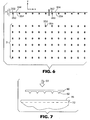
- One example of a mask pattern useful for forming a structured surface for the eventual production of an array of microneedles with channels and conduits in fluid communication with the channels is depicted in
FIG 6 . The mask pattern includes one row ofneedle apertures 350 aligned in the x direction as seen inFIG 6 . The row ofneedle apertures 350 is interconnected by one set ofbarrier apertures 354 corresponding to the barriers in the conduit structures. Thebarrier apertures 354 extend in both the x and y directions, i.e., along the row ofneedle apertures 350 and in the y direction at the ends of the barrier apertures The portions of thebarrier apertures 354 that extend in the y direction are used to form the barriers of the main arteries (see, e.g.,FIG. 1 ). - In addition, each of the
needle apertures 350 includes achannel feature 352 corresponding to the desired location of the channel on the microneedle corresponding to the needle aperture. - The mask itself may, e.g., be manufactured using standard semiconductor lithography mask techniques. The patterned portions of the mask are opaque to the laser energy used to pattern the substrate, e.g., ultraviolet light in the case of excimer laser energy The mask may include a support substrate that is transparent to the laser energy. For example, the patterned portions may be formed of aluminum while the support substrate is fused silica. One alternative for the aluminum may be a dielectric stack that is opaque for light of the desired wavelengths.
- The
needle apertures 350 in the mask are preferably arranged in successive rows that are uniformly spaced apart (along the x axis). It is further preferred that the spacing between the needle apertures along the rows are also uniform (along the y axis) With uniform spacing between the needle apertures and associated conduit apertures, laser ablation processes similar in many respects to those described inWO-A-96/33839 - One of the ways in which the preferred laser ablation process differs from that disclosed in
WO-A-96/33839 - By providing both the needle apertures and the barrier apertures in the same mask, the present invention provides a number of advantages Among those advantages is the ability to provide microneedles and the associated conduit structures in registration with each other because the features can be imaged at the same time. This can be particularly important in producing devices such as microneedle arrays in which the features are spaced apart in distances measured in micrometers.
- Control over the depth of the different cavities formed in the substrate (corresponding to the different heights of the microneedles and barriers on the microneedle arrays) can be obtained by, e.g., selectively covering or masking the different features on the mask while ablating the urnderlying substrate through the apertures that are not covered or masked. That process can be used, e.g., to obtain barrier cavities that are shallower than the microneedle cavities
- Use of the mask pattern depicted in
FIG. 6 , for example, may proceed with a first exposure of the substrate located beneath portion A of the mask pattern, i.e., the row ofneedle apertures 350 interconnected by thebarrier apertures 354. As a result, the substrate is exposed during the first exposure in a pattern corresponding to portion A of the mask pattern. - Movement of the mask pattern and the substrate being exposed relative to each other in the y direction can then be used to align the
mask apertures 350 in the uppermost row of portion B with the parts of the substrate exposed by theneedle apertures 350 in portion A during the first exposure A second exposure then results in another exposure through the needle apertures to ablate more of the substrate, thereby increasing the depth of the needle cavities in the substrate without also increasing the depth of the barrier cavities Step-wise movement and exposure can then be repeated until the needle cavities and the barrier cavities are formed to the desired depth in the substrate. - Control over the wall angles of the needle cavities may be achieved by any suitable technique or combination of techniques Examples of suitable techniques may be described in, eg., T. Hodapp et el, "Modeling Topology Formation During Laser Ablation," J Appl. Physics, Vol 84, No. 1, pp. 577-583 (July 1, 1998).
- When processing a polyimide mold substrate through laser ablation, it may be preferred that the mold substrate be located in an oxygen atmosphere to improve subsequent plating of the cavities thus formed
- After completion of the structured surface, the substrate provides a negative of the desired microneedle array structure, with needle cavities corresponding to the shape of the microneedles and conduit cavities corresponding to the desired shape of the conduit structures. As for the needle cavities, they arc preferably generally tapered in shape, with a channel structure extending into the tapered shape of the needle cavity
- The resulting mold substrate is then preferably electroplated to form a metallic positive of the microneedle array. Before electroplating, however, the substrate may preferably be cleaned to remove any debris that is, e.g., associated with the laser ablation processing used to form the negative image in the substrate. One suitable cleaning process may include locating the substrate in an ultrasonic bath of detergent and water, followed by drying.
- After cleaning the mold substrate, a seed layer of one or more conductive metals is preferably first deposited to provide a conductive surface, followed by heavier electroplating in, e.g., a nickel bath The seed layer may be deposited by sputtering, chemical vapor deposition, a silver bath, or any other suitable method. To enhance proper filling of the cavities and fidelity of the resulting microneedles to the shape of the cavities, it may be preferred that the seeding be continued until a thicker seed layer is deposited. For example, it may be preferred that the seed layer be deposited with a thickness of about 0.5 micrometers or more, possibly even about 1 micrometer.
- Following formation of the seed layer, the seeded mold substrate can then be electroformed with a thicker layer of, e.g., nickel, to form a metallic microneedle array. After filling the cavities in the mold substrate, the plating process is preferably continued until a backplate is formed on the mold substrate with a thickness sufficient to support the microneedle array. For example, a backplate with a thickness of about 0.5 millimeters to about 3 millimeters or more may be formed. If desired, the surface of the backplate opposite the microneedle structures may be polished. That polishing may preferably be carried out while the substrate is still attached to a base layer as described above
- After the metallic microneeclle array is formed, the mold substrate can be removed from the microneedle array by any suitable technique or combination of techniques. Some suitable techniques include, but are not limited to, chemical etching, shock freezing, laser ablation, etc. For example, a polyimide substrate may be removed from a microneedle array using an etchant, e.g., potassium hydroxide (KOH).
- Because the needle cavities in the structured surface may have a relatively high aspect ratio, it may be desirable to use an electroplating process capable of accurately filling the high aspect ratio cavities. For example, it may be desirable to carry out the electroplating process in the presence of ultrasonic energy for at least a portion of the electroplating. Examples of some suitable systems for and processes of electroplating in the presence of ultrasonic energy may be described in e.g.,
US-3-6, 746, 590 - The microneedle arrays of the invention may be used in a variety of different manners One manner of using microneedle arrays of the present invention is in methods involving the penetration of skin to deliver medicaments or other substances and/or extract blood or tissue. As discussed above, it may be desired that the height of the microneedles in the microneedle arrays be sufficient to penetrate the stratum corneum.
- In addition to having a sufficient length, it may be preferred to provide the microneedle arrays in combination with devices that are capable of delivering the microneedle arrays to a skin impact site in a manner that results in effective piercing of the stratum corneum by the microneedles on the array. Delivery of a microneedle array in accordance with the methods of the present invention will involve application of an impact force to the microneedle array over a short period of time (typically less than about 1 second) such that the microneedles of the array are driven through the stratum corneum at the skin impact site Application of the impact force may rapidly accelerate the microneedle arrays of the present invention such that impact delivery of the microneedle array with the skin is achieved.
- It should be understood that impact delivery of microneedle arrays as discussed herein may not necessarily be limited to microneedle arrays that include microneedles with channels as described above in connection with
FIGS. 1-6 . The impact delivery devices and methods described herein may be used with many different microneedle arrays. - Referring to
FIG. 7 , one method of forcing amicroneedle array 60 includingmicroneedles 62 is depicted, with themicroneedle array 60 being forced against the skin 70 (with stratum corneum 72) by animpact force 64.FIG. 8 depicts themicroneedle array 60 in contact with theskin 70, such that themicroneedles 62 penetrate thestratum corneum 72. - The impact force magnitude and duration period are selected to provide effective penetration of the stratum corneum by the microneedles. It may be preferred that the period of time over which the impact force is applied be less than about 500 milliseconds, in some instances, the period may preferably be about 300 milliseconds or less.
- The impact force may be applied in a variety of manners. For example, the
microneedle array 60 may be positioned a distance from the skin impact site, such that application of theimpact force 64 results in acceleration of themicroneedle array 60 towards the skin impact site until the microneedle array contacts the skin impact site. In another example, the microneedle array may be positioned in contact with the skin impact site before the impact force is applied to the microneedle array, such that application of the force does not result in acceleration as would be achieved if the microneedle array is positioned away from the skin. - After application of the impact force and subsequent driving of the microneedles through the stratum comcum, it may be desired to remove the microneedle array from contact with the skin impact site within about 1 second or less. In other instances, it may be desirable to retain the microneedle array in contact with the skin impact site for a longer period of time, e.g., about 2 seconds or more.
- The maximum magnitude of the impact force may preferably be limited to, e.g., control the pain associated with impact delivery of microneedles arrays in connection with the present invention. For example, it may be preferred to provide impact delivery of the microneedle arrays of the present invention with a maximum impact force about 40 N/cm2 or less, more preferably about 20 N/cm2.
- At the other end of the force spectrum, the minimum impact force may vary depending on a variety of factors such as the size of the microneedle array, the size and/or shape of the microneedles, etc.
- A wide variety of devices may be used to provide the desired impact delivery of microneedle arrays with the skin of a subject. One
such device 68 is illustrated schematically inFIG. 9 as including amicroneedle array 60 and adriver 66. Thedevice 68 may be a single-use disposable design, it may be designed for using asingle microneedle array 60, or it may be designed to use multipledifferent microneedles arrays 60 - The
driver 66 may be provided by any mechanism capable of applying the desired impact force needed to drive the microneedles into the stratum corneum as discussed above. Thedriver 66 may be in the form of any device capable of releasing stored energy in the form of the impact force over the durations discussed above, i e., over a period of less than about 1 second. For example, thedriver 66 may include a mechanical spring (e g., a coil spring, leaf spring, etc.), compressed resilient member (eg, rubber, etc.), compressed fluids (e.g., air, liquids, etc.), piezoelectric structure, electromagnetic structure, hammer device, etc. - One example of a potentially
suitable device 68 may include a lancet driver incorporating a mechanical spring which may be modified, if needed, to provide the desired force to the microneedle array. Typically, a lancet driver may also require some modifications to ensure that the microneedle array is forced against the skin in a manner such that substantially all of the microneedles contact the skin - Following impact delivery of a microneedle array may be desirable to provide vacuum over the surface of the skin impacted by the microneedle array Application of vacuum to the impact site can be used to extract blood or fluid from the skin penetrated by the microneedles.
- Referring to
FIG. 10 , avacuum cup 90 is depicted over the skin impact site as depicted in, e.g.,FIG. 8 . Thevacuum cup 90 may preferably include aport 94 that allows for evacuation of thevolume 92 defined by thevacuum cup 90. As used in connection with the present invention, "vacuum" is defined as a pressure below the ambient atmospheric pressure surrounding the vacuum cup. The vacuum may be provided by any suitable source, e.g., a pump, syringe, etc. - The microneedles driven into the stratum corneum at the skin delivery site may provide fluid pathways through the stratum corneum. A vacuum applied over the skin delivery site after the microneedles have been driven into the stratum corneum may enhance the passage of fluids through the stratum corneum within the skin delivery site.
- The ability of the vacuum drawn within
volume 92 to draw fluids through the skin in the skin impact site may be used for a variety of purposes. For example, anindicator 80 capable of detecting the presence or absence of substances or materials in fluids drawn out from the skin impact site may be located on the skin impact site. Theindicator 80 may be placed in contact with the skin delivery site before drawing the vacuum over that site or after drawing the vacuum over the skin impact site. - For example, a blood
glucose monitoring strip 80 may be placed over the skin impact site with the fluid drawn through the impact site activating the strip to provide a glucose reading. In such a method, sufficient fluid may be drawn under, e.g., conditions of 0.5 atm of vacuum for less than 1 minute. - In addition to indicators for determining blood-glucose levels, the device and methods of the present invention may be used to extract fluid for other indicators such as those capable of determining the presence, absence or amounts of a variety of materials in fluids (e.g., blood) such as dissolved oxygen, carbon dioxide, lacti acid, illicit drugs, etc.
- Additionally, the demonstration of effective penetration of the stratum corneum may provide a useful pathway for localized, painless administration of pharmaceuticals. Topically applied pharmaceuticals may be more effectively delivered through the skin after penetration of the stratum corneum by the microneedle arrays of the present invention. In other variations, the microneedle array penetration may be coupled with an electrical or ultrasonic device to deliver larger drugs through the skin more rapidly that is possible through uncompromised tissue
- Where used for the delivery of medicaments or other substances (or the removal of fluids), it may be desirable to include one or more reservoirs in fluid communication with the conduit structures formed in the microneedle arrays. Examples of such reservoirs may be described in, e.g.,
U S-A-3,964,482 . The reservoirs may be in fluid communication with the conduit structures on the front side of the microneedle arrays (i.e., the side from which the microneedles project) or they may be in fluid communication with the conduit structure from the back side (i.e., the side opposite the front side) through vias or other fluid pathways. - Various modifications and alterations of this invention will become apparent to those skilled in the art without departing from the scope of this invention, and it should be understood that this invention is not to be unduly limited to the illustrative embodiments set forth herein.
Claims (7)
- A microneedle array device comprising- a plurality of microneedles (20,120,220,320,420,520,620) projecting from a substrate surface (12,412), wherein each of the microneedles (20,120,220,320,420,520,620) comprises a tapered shape comprising an outer surface, a base (26,126,226,326) proximate the substrate surface (12,412) and a tip (24,124,224,324,424,524,624) distal from the base (26,126,226,326),- wherein each microneedle (20,120,220,320,420,520,620) of the plurality of microneedles (20,120,220,320,420,520,620) is provided with a channel (22,122,212,322,622) extending from the base (26,126,226,326) of the microneedle (20,120,220,320,420,520,620) towards its tip (24,124,224,324,424,524,624),characterized in that- each channel (22,122,212,322,622) is formed in the outer surface of the microneedle (20,120,220,320,420,520,620) extending along the outer surface from the base (26,126,226,326) towards the tip (24,124,224,324,424,524,624) of the microneedle (20,120,220,320, 420,520,620) and terminating short of the tip (24,124,224,324,424, 524,624) of the microneedle (20,120,220,320,420,520,620).
- The microneedle array device as claimed in claim 1, and further wherein the base (26,126,226,326) is elongated along an elongation axis (11,111,211) on the substrate surface (12,412) such that the base (26,126,226,326) comprises opposing ends along the elongation axis (11,111,211); and wherein each channel (22,122,212,322,622) extends from one of the opposing ends of the elongated base (26,126,226,326) towards the tip (24,124,224,324,424,524,624) of the microneedle (20,120,220,320,420,520,620).
- The microneedle array device according to claim 2, wherein the channel (22,122,212,322,622) extends from an intermediate location between the opposing ends of the elongated base (26,126,226,326) towards the tip (24,124,224,324,424,524,624) of the microneedle (20,120,220,320,420, 520,620).
- The microneedle array device according to claim 2 or 3, wherein the channel (22,122,212,322,622) comprises a channel depth, and wherein the channel depth at the base (26,126,226,326) of the microneedle (20,120,220,320,420,520,620) is less than half of the dimension of the base (26,126,226,326) as measured between the opposing ends.
- The microneedle array device according to claim 1 or 2, wherein the base (26,126,226,326) comprises an oval.
- The microneedle array device according to any one of claims 1 to 5, further comprising a conduit structure (32,34) formed on the substrate surface (12,412), wherein the channel (22,122,212,322,622) in each microneedle (20,120,220,320,420,520,620) of the plurality of microneedles (20,120,220,320,420,520,620) is in fluid communication with the conduit structure (32,34) on the substrate surface (12,412).
- The microneedle array device according to claim 6, wherein the conduit structure (32,34) comprises a series of barriers (36) projecting from the substrate surface (12,412), with fluid pathways of the conduit structure (32,34) being defined by the barriers (36).
Applications Claiming Priority (2)
| Application Number | Priority Date | Filing Date | Title |
|---|---|---|---|
| US09/947,195 US6881203B2 (en) | 2001-09-05 | 2001-09-05 | Microneedle arrays and methods of manufacturing the same |
| EP02750036A EP1425062A2 (en) | 2001-09-05 | 2002-07-15 | Microneedle arrays and methods of manufacturing the same |
Related Parent Applications (1)
| Application Number | Title | Priority Date | Filing Date |
|---|---|---|---|
| EP02750036A Division EP1425062A2 (en) | 2001-09-05 | 2002-07-15 | Microneedle arrays and methods of manufacturing the same |
Publications (3)
| Publication Number | Publication Date |
|---|---|
| EP1652551A2 EP1652551A2 (en) | 2006-05-03 |
| EP1652551A3 EP1652551A3 (en) | 2006-05-31 |
| EP1652551B1 true EP1652551B1 (en) | 2008-03-26 |
Family
ID=25485700
Family Applications (2)
| Application Number | Title | Priority Date | Filing Date |
|---|---|---|---|
| EP02750036A Withdrawn EP1425062A2 (en) | 2001-09-05 | 2002-07-15 | Microneedle arrays and methods of manufacturing the same |
| EP06101150A Expired - Lifetime EP1652551B1 (en) | 2001-09-05 | 2002-07-15 | Microneedle arrays |
Family Applications Before (1)
| Application Number | Title | Priority Date | Filing Date |
|---|---|---|---|
| EP02750036A Withdrawn EP1425062A2 (en) | 2001-09-05 | 2002-07-15 | Microneedle arrays and methods of manufacturing the same |
Country Status (8)
| Country | Link |
|---|---|
| US (2) | US6881203B2 (en) |
| EP (2) | EP1425062A2 (en) |
| JP (1) | JP2005501615A (en) |
| AT (1) | ATE390167T1 (en) |
| DE (1) | DE60225859T2 (en) |
| ES (1) | ES2304758T3 (en) |
| TW (1) | TW550101B (en) |
| WO (1) | WO2003020359A2 (en) |
Families Citing this family (301)
| Publication number | Priority date | Publication date | Assignee | Title |
|---|---|---|---|---|
| US6036924A (en) | 1997-12-04 | 2000-03-14 | Hewlett-Packard Company | Cassette of lancet cartridges for sampling blood |
| US6391005B1 (en) | 1998-03-30 | 2002-05-21 | Agilent Technologies, Inc. | Apparatus and method for penetration with shaft having a sensor for sensing penetration depth |
| US6603987B2 (en) * | 2000-07-11 | 2003-08-05 | Bayer Corporation | Hollow microneedle patch |
| US7108681B2 (en) * | 2000-10-16 | 2006-09-19 | Corium International, Inc. | Microstructures for delivering a composition cutaneously to skin |
| US7828827B2 (en) | 2002-05-24 | 2010-11-09 | Corium International, Inc. | Method of exfoliation of skin using closely-packed microstructures |
| US8641644B2 (en) | 2000-11-21 | 2014-02-04 | Sanofi-Aventis Deutschland Gmbh | Blood testing apparatus having a rotatable cartridge with multiple lancing elements and testing means |
| US6663820B2 (en) * | 2001-03-14 | 2003-12-16 | The Procter & Gamble Company | Method of manufacturing microneedle structures using soft lithography and photolithography |
| CN100349632C (en) * | 2001-04-20 | 2007-11-21 | 阿尔扎公司 | Microprojection array having beneficial agent contg coating |
| US9795747B2 (en) | 2010-06-02 | 2017-10-24 | Sanofi-Aventis Deutschland Gmbh | Methods and apparatus for lancet actuation |
| US9226699B2 (en) | 2002-04-19 | 2016-01-05 | Sanofi-Aventis Deutschland Gmbh | Body fluid sampling module with a continuous compression tissue interface surface |
| US8337419B2 (en) | 2002-04-19 | 2012-12-25 | Sanofi-Aventis Deutschland Gmbh | Tissue penetration device |
| US7025774B2 (en) | 2001-06-12 | 2006-04-11 | Pelikan Technologies, Inc. | Tissue penetration device |
| EP1404233B1 (en) | 2001-06-12 | 2009-12-02 | Pelikan Technologies Inc. | Self optimizing lancing device with adaptation means to temporal variations in cutaneous properties |
| EP1404235A4 (en) | 2001-06-12 | 2008-08-20 | Pelikan Technologies Inc | Method and apparatus for lancet launching device integrated onto a blood-sampling cartridge |
| US7682318B2 (en) | 2001-06-12 | 2010-03-23 | Pelikan Technologies, Inc. | Blood sampling apparatus and method |
| ATE497731T1 (en) | 2001-06-12 | 2011-02-15 | Pelikan Technologies Inc | DEVICE FOR INCREASING THE SUCCESS RATE OF BLOOD YIELD OBTAINED BY A FINGER PICK |
| US7981056B2 (en) | 2002-04-19 | 2011-07-19 | Pelikan Technologies, Inc. | Methods and apparatus for lancet actuation |
| JP4149911B2 (en) | 2001-06-12 | 2008-09-17 | ペリカン テクノロジーズ インコーポレイテッド | Electric lancet actuator |
| US9427532B2 (en) | 2001-06-12 | 2016-08-30 | Sanofi-Aventis Deutschland Gmbh | Tissue penetration device |
| US20040087992A1 (en) * | 2002-08-09 | 2004-05-06 | Vladimir Gartstein | Microstructures for delivering a composition cutaneously to skin using rotatable structures |
| US6908453B2 (en) * | 2002-01-15 | 2005-06-21 | 3M Innovative Properties Company | Microneedle devices and methods of manufacture |
| ES2406711T3 (en) | 2002-03-26 | 2013-06-07 | Becton, Dickinson And Company | Multi-stage fluid supply device |
| US7226461B2 (en) | 2002-04-19 | 2007-06-05 | Pelikan Technologies, Inc. | Method and apparatus for a multi-use body fluid sampling device with sterility barrier release |
| US7331931B2 (en) | 2002-04-19 | 2008-02-19 | Pelikan Technologies, Inc. | Method and apparatus for penetrating tissue |
| US7717863B2 (en) | 2002-04-19 | 2010-05-18 | Pelikan Technologies, Inc. | Method and apparatus for penetrating tissue |
| US8702624B2 (en) | 2006-09-29 | 2014-04-22 | Sanofi-Aventis Deutschland Gmbh | Analyte measurement device with a single shot actuator |
| US7892183B2 (en) | 2002-04-19 | 2011-02-22 | Pelikan Technologies, Inc. | Method and apparatus for body fluid sampling and analyte sensing |
| US7232451B2 (en) | 2002-04-19 | 2007-06-19 | Pelikan Technologies, Inc. | Method and apparatus for penetrating tissue |
| US7229458B2 (en) | 2002-04-19 | 2007-06-12 | Pelikan Technologies, Inc. | Method and apparatus for penetrating tissue |
| US9248267B2 (en) | 2002-04-19 | 2016-02-02 | Sanofi-Aventis Deustchland Gmbh | Tissue penetration device |
| US7291117B2 (en) | 2002-04-19 | 2007-11-06 | Pelikan Technologies, Inc. | Method and apparatus for penetrating tissue |
| US8267870B2 (en) | 2002-04-19 | 2012-09-18 | Sanofi-Aventis Deutschland Gmbh | Method and apparatus for body fluid sampling with hybrid actuation |
| US7175642B2 (en) | 2002-04-19 | 2007-02-13 | Pelikan Technologies, Inc. | Methods and apparatus for lancet actuation |
| US9314194B2 (en) | 2002-04-19 | 2016-04-19 | Sanofi-Aventis Deutschland Gmbh | Tissue penetration device |
| US8221334B2 (en) | 2002-04-19 | 2012-07-17 | Sanofi-Aventis Deutschland Gmbh | Method and apparatus for penetrating tissue |
| US7976476B2 (en) | 2002-04-19 | 2011-07-12 | Pelikan Technologies, Inc. | Device and method for variable speed lancet |
| US7547287B2 (en) | 2002-04-19 | 2009-06-16 | Pelikan Technologies, Inc. | Method and apparatus for penetrating tissue |
| US7491178B2 (en) | 2002-04-19 | 2009-02-17 | Pelikan Technologies, Inc. | Method and apparatus for penetrating tissue |
| US7297122B2 (en) | 2002-04-19 | 2007-11-20 | Pelikan Technologies, Inc. | Method and apparatus for penetrating tissue |
| US7371247B2 (en) | 2002-04-19 | 2008-05-13 | Pelikan Technologies, Inc | Method and apparatus for penetrating tissue |
| US8784335B2 (en) | 2002-04-19 | 2014-07-22 | Sanofi-Aventis Deutschland Gmbh | Body fluid sampling device with a capacitive sensor |
| US9795334B2 (en) | 2002-04-19 | 2017-10-24 | Sanofi-Aventis Deutschland Gmbh | Method and apparatus for penetrating tissue |
| US8579831B2 (en) | 2002-04-19 | 2013-11-12 | Sanofi-Aventis Deutschland Gmbh | Method and apparatus for penetrating tissue |
| US7648468B2 (en) | 2002-04-19 | 2010-01-19 | Pelikon Technologies, Inc. | Method and apparatus for penetrating tissue |
| US7674232B2 (en) | 2002-04-19 | 2010-03-09 | Pelikan Technologies, Inc. | Method and apparatus for penetrating tissue |
| US7901362B2 (en) | 2002-04-19 | 2011-03-08 | Pelikan Technologies, Inc. | Method and apparatus for penetrating tissue |
| US7909778B2 (en) | 2002-04-19 | 2011-03-22 | Pelikan Technologies, Inc. | Method and apparatus for penetrating tissue |
| MXPA05000597A (en) * | 2002-07-19 | 2005-04-28 | 3M Innovative Properties Co | Microneedle devices and microneedle delivery apparatus. |
| CN100479875C (en) | 2002-07-22 | 2009-04-22 | 贝克顿·迪金森公司 | Patch-like infusion device |
| US8574895B2 (en) | 2002-12-30 | 2013-11-05 | Sanofi-Aventis Deutschland Gmbh | Method and apparatus using optical techniques to measure analyte levels |
| US7578954B2 (en) * | 2003-02-24 | 2009-08-25 | Corium International, Inc. | Method for manufacturing microstructures having multiple microelements with through-holes |
| US7415299B2 (en) * | 2003-04-18 | 2008-08-19 | The Regents Of The University Of California | Monitoring method and/or apparatus |
| US7850621B2 (en) | 2003-06-06 | 2010-12-14 | Pelikan Technologies, Inc. | Method and apparatus for body fluid sampling and analyte sensing |
| WO2006001797A1 (en) | 2004-06-14 | 2006-01-05 | Pelikan Technologies, Inc. | Low pain penetrating |
| TW200518771A (en) * | 2003-06-30 | 2005-06-16 | Alza Corp | Formulations for coated microprojections containing non-volatile counterions |
| US20050123507A1 (en) * | 2003-06-30 | 2005-06-09 | Mahmoud Ameri | Formulations for coated microprojections having controlled solubility |
| CA2535138C (en) | 2003-08-12 | 2013-01-08 | Becton, Dickinson And Company | Patch-like infusion device |
| WO2005020912A2 (en) * | 2003-08-25 | 2005-03-10 | 3M Innovative Properties Company | Delivery of immune response modifier compounds |
| WO2005018731A1 (en) * | 2003-08-26 | 2005-03-03 | Alza Corporation | Device and method for intradermal cell implantation |
| EP1671096A4 (en) | 2003-09-29 | 2009-09-16 | Pelikan Technologies Inc | Method and apparatus for an improved sample capture device |
| WO2005037095A1 (en) | 2003-10-14 | 2005-04-28 | Pelikan Technologies, Inc. | Method and apparatus for a variable user interface |
| US20090054842A1 (en) * | 2003-11-18 | 2009-02-26 | Nanopass Technologies Ltd. | Enhanced penetration system and method for sliding microneedles |
| WO2005060621A2 (en) * | 2003-11-21 | 2005-07-07 | The Regents Of The University Of California | Method and/or apparatus for puncturing a surface for extraction, in situ analysis, and/or substance delivery using microneedles |
| CA2552385C (en) | 2003-12-29 | 2013-07-23 | 3M Innovative Properties Company | Medical devices and kits including same |
| US7822454B1 (en) | 2005-01-03 | 2010-10-26 | Pelikan Technologies, Inc. | Fluid sampling device with improved analyte detecting member configuration |
| US8668656B2 (en) | 2003-12-31 | 2014-03-11 | Sanofi-Aventis Deutschland Gmbh | Method and apparatus for improving fluidic flow and sample capture |
| GB0402131D0 (en) | 2004-01-30 | 2004-03-03 | Isis Innovation | Delivery method |
| US8551391B2 (en) * | 2004-02-17 | 2013-10-08 | Avery Dennison Corporation | Method of making microneedles |
| US20070191761A1 (en) * | 2004-02-23 | 2007-08-16 | 3M Innovative Properties Company | Method of molding for microneedle arrays |
| JP2005246595A (en) * | 2004-03-05 | 2005-09-15 | Ritsumeikan | Microneedle array and method of producing the same |
| WO2005087305A1 (en) * | 2004-03-12 | 2005-09-22 | Agency For Science, Technology And Research | Methods and moulds for use in fabricating side-ported microneedles |
| WO2005094526A2 (en) * | 2004-03-24 | 2005-10-13 | Corium International, Inc. | Transdermal delivery device |
| CA2562643A1 (en) * | 2004-04-12 | 2005-11-24 | Allergan, Inc. | Multi-site injection system |
| JP5007427B2 (en) | 2004-05-13 | 2012-08-22 | アルザ コーポレイション | Apparatus and method for transdermal delivery of parathyroid hormone agents |
| EP1751546A2 (en) | 2004-05-20 | 2007-02-14 | Albatros Technologies GmbH & Co. KG | Printable hydrogel for biosensors |
| WO2005120365A1 (en) | 2004-06-03 | 2005-12-22 | Pelikan Technologies, Inc. | Method and apparatus for a fluid sampling device |
| ES2650188T3 (en) | 2004-06-10 | 2018-01-17 | 3M Innovative Properties Company | Device and patch application kit |
| US7560036B2 (en) * | 2004-08-05 | 2009-07-14 | Apogee Technology, Inc. | System and method for drug delivery and microfluidic applications using microneedles |
| US8696619B2 (en) | 2004-08-10 | 2014-04-15 | Robert P. Schnall | Drug delivery devices |
| JPWO2006016647A1 (en) * | 2004-08-12 | 2008-05-01 | 久光製薬株式会社 | Transdermal drug administration device with microneedle |
| EP2289646B1 (en) | 2004-08-16 | 2014-02-12 | Functional Microstructures Limited | Device to be applied to a biological barrier |
| SE0402100D0 (en) * | 2004-08-30 | 2004-08-30 | Bonsens Ab | Molded micro-needles |
| GB0420256D0 (en) | 2004-09-13 | 2004-10-13 | Cassells John M | Method and apparatus for sampling and analysis of fluids |
| WO2006055795A1 (en) | 2004-11-18 | 2006-05-26 | 3M Innovative Properties Company | Low-profile microneedle array applicator |
| US8057842B2 (en) | 2004-11-18 | 2011-11-15 | 3M Innovative Properties Company | Method of contact coating a microneedle array |
| ATE504328T1 (en) | 2004-11-18 | 2011-04-15 | 3M Innovative Properties Co | MICRONEEDLE ARRANGEMENT APPLICATOR AND HOLDER |
| EP2388078B1 (en) | 2004-11-18 | 2013-03-20 | 3M Innovative Properties Co. | Method of contact coating a microneedle array |
| AU2005306426B2 (en) * | 2004-11-18 | 2011-04-28 | 3M Innovative Properties Company | Masking method for coating a microneedle array |
| US20080307849A1 (en) * | 2004-11-26 | 2008-12-18 | Agency For Science, Technology And Research | Method And Apparatus For Forming Microstructures |
| ATE468961T1 (en) | 2004-12-07 | 2010-06-15 | 3M Innovative Properties Co | METHOD FOR SHAPING A MICRONEEDLE |
| ES2354081T3 (en) * | 2004-12-10 | 2011-03-09 | 3M Innovative Properties Company | MEDICAL DEVICE. |
| US7588705B2 (en) * | 2004-12-28 | 2009-09-15 | Nabtesco Corporation | Skin needle manufacturing apparatus and skin needle manufacturing method |
| US8652831B2 (en) | 2004-12-30 | 2014-02-18 | Sanofi-Aventis Deutschland Gmbh | Method and apparatus for analyte measurement test time |
| WO2006075689A1 (en) * | 2005-01-14 | 2006-07-20 | Fujikura Ltd. | Drug delivery instrument and method of producing the same |
| JP4793806B2 (en) * | 2005-03-22 | 2011-10-12 | Tti・エルビュー株式会社 | Iontophoresis device |
| WO2006105146A2 (en) * | 2005-03-29 | 2006-10-05 | Arkal Medical, Inc. | Devices, systems, methods and tools for continuous glucose monitoring |
| JP5301985B2 (en) | 2005-04-07 | 2013-09-25 | スリーエム イノベイティブ プロパティズ カンパニー | System and method for tool feedback sensing |
| GB0509863D0 (en) * | 2005-05-16 | 2005-06-22 | Cambridge Biostability Ltd | Apparatus for administrating substances into a body |
| US20080195035A1 (en) | 2005-06-24 | 2008-08-14 | Frederickson Franklyn L | Collapsible Patch and Method of Application |
| WO2007002522A1 (en) | 2005-06-27 | 2007-01-04 | 3M Innovative Properties Company | Microneedle cartridge assembly and method of applying |
| EP2474338B1 (en) | 2005-06-27 | 2013-07-24 | 3M Innovative Properties Company | Microneedle array applicator device |
| US20070004989A1 (en) * | 2005-06-29 | 2007-01-04 | Parvinder Dhillon | Device for transdermal sampling |
| US20070078414A1 (en) * | 2005-08-05 | 2007-04-05 | Mcallister Devin V | Methods and devices for delivering agents across biological barriers |
| RU2008114490A (en) * | 2005-09-15 | 2009-10-20 | ТиТиАй ЭЛЛЕБО, ИНК. (JP) | STEM TYPE IONTOPHORESIS DEVICE |
| US20070066934A1 (en) * | 2005-09-19 | 2007-03-22 | Transport Pharmaceuticals, Inc. | Electrokinetic delivery system and methods therefor |
| US20070185432A1 (en) * | 2005-09-19 | 2007-08-09 | Transport Pharmaceuticals, Inc. | Electrokinetic system and method for delivering methotrexate |
| US20070073212A1 (en) * | 2005-09-28 | 2007-03-29 | Takehiko Matsumura | Iontophoresis apparatus and method to deliver active agents to biological interfaces |
| KR20080080087A (en) * | 2005-09-30 | 2008-09-02 | 티티아이 엘뷰 가부시키가이샤 | Transdermal drug delivery systems, devices, and methods employing novel pharmaceutical vehicles |
| JP2009509677A (en) * | 2005-09-30 | 2009-03-12 | Tti・エルビュー株式会社 | Iontophoretic delivery of vesicle encapsulated active substances |
| KR20080066712A (en) * | 2005-09-30 | 2008-07-16 | 티티아이 엘뷰 가부시키가이샤 | Functionalized microneedles transdermal drug delivery systems, devices, and methods |
| US20070078376A1 (en) * | 2005-09-30 | 2007-04-05 | Smith Gregory A | Functionalized microneedles transdermal drug delivery systems, devices, and methods |
| US7574256B2 (en) * | 2005-09-30 | 2009-08-11 | Tti Ellebeau, Inc. | Iontophoretic device and method of delivery of active agents to biological interface |
| US20070093789A1 (en) * | 2005-09-30 | 2007-04-26 | Transcutaneous Technologies Inc. | Iontophoresis apparatus and method for delivery of angiogenic factors to enhance healing of injured tissue |
| WO2007061781A1 (en) * | 2005-11-18 | 2007-05-31 | 3M Innovative Properties Company | Coatable compositions, coatings derived therefrom and microarrays having such coatings |
| US20080262416A1 (en) * | 2005-11-18 | 2008-10-23 | Duan Daniel C | Microneedle Arrays and Methods of Preparing Same |
| WO2007064486A1 (en) | 2005-11-30 | 2007-06-07 | 3M Innovative Properties Company | Microneedle arrays and methods of use thereof |
| EP1959731A1 (en) * | 2005-12-14 | 2008-08-27 | Ariana Holdings Pty Ltd | Chemical applicator |
| EP1962942A1 (en) * | 2005-12-21 | 2008-09-03 | 3M Innovative Properties Company | Microneedle devices |
| WO2007079116A1 (en) * | 2005-12-28 | 2007-07-12 | Tti Ellebeau, Inc. | Electroosmotic pump apparatus and method to deliver active agents to biological interfaces |
| JP2009522011A (en) * | 2005-12-30 | 2009-06-11 | Tti・エルビュー株式会社 | Iontophoresis system, apparatus and method for delivering an active substance to a biological interface |
| US9339641B2 (en) | 2006-01-17 | 2016-05-17 | Emkinetics, Inc. | Method and apparatus for transdermal stimulation over the palmar and plantar surfaces |
| US20100168501A1 (en) * | 2006-10-02 | 2010-07-01 | Daniel Rogers Burnett | Method and apparatus for magnetic induction therapy |
| US9610459B2 (en) * | 2009-07-24 | 2017-04-04 | Emkinetics, Inc. | Cooling systems and methods for conductive coils |
| JPWO2007091608A1 (en) * | 2006-02-10 | 2009-07-02 | 久光製薬株式会社 | Transdermal drug administration device with microneedle |
| US7699819B2 (en) | 2006-02-21 | 2010-04-20 | The Hong Kong University Of Science And Technology | Molecular sieve and zeolite microneedles and preparation thereof |
| GB0605003D0 (en) * | 2006-03-13 | 2006-04-19 | Microsample Ltd | Method and apparatus for piercing the skin and delivery or collection of liquids |
| WO2007112309A2 (en) * | 2006-03-24 | 2007-10-04 | 3M Innovative Properties Company | Process for making microneedles, microneedle arrays, masters, and replication tools |
| US20080154107A1 (en) * | 2006-12-20 | 2008-06-26 | Jina Arvind N | Device, systems, methods and tools for continuous glucose monitoring |
| US20100049021A1 (en) * | 2006-03-28 | 2010-02-25 | Jina Arvind N | Devices, systems, methods and tools for continuous analyte monitoring |
| US20090131778A1 (en) * | 2006-03-28 | 2009-05-21 | Jina Arvind N | Devices, systems, methods and tools for continuous glucose monitoring |
| WO2007123707A1 (en) * | 2006-03-30 | 2007-11-01 | Tti Ellebeau, Inc. | Controlled release membrane and methods of use |
| JP4908893B2 (en) * | 2006-03-30 | 2012-04-04 | 久光製薬株式会社 | Medicinal product carrying device, method for producing the same, and method for producing a mold for producing a medicinal product carrying device |
| CN100441388C (en) * | 2006-04-06 | 2008-12-10 | 上海交通大学 | Microneedle preparation method based on multiplayer processing technology |
| JP5049268B2 (en) * | 2006-04-07 | 2012-10-17 | 久光製薬株式会社 | Microneedle device and transdermal drug administration device with microneedle |
| US9119945B2 (en) * | 2006-04-20 | 2015-09-01 | 3M Innovative Properties Company | Device for applying a microneedle array |
| US20070276330A1 (en) * | 2006-05-28 | 2007-11-29 | Beck Patricia A | Microneedles and methods of fabricating thereof |
| JP4904964B2 (en) * | 2006-07-24 | 2012-03-28 | 凸版印刷株式会社 | Manufacturing method of needle-shaped body |
| DE102006036331A1 (en) | 2006-08-03 | 2008-02-14 | Stephan Hammelbacher | Device and method for marking objects |
| EP2062611A4 (en) * | 2006-08-18 | 2010-01-06 | Toppan Printing Co Ltd | Microneedle and microneedle patch |
| US20080058726A1 (en) * | 2006-08-30 | 2008-03-06 | Arvind Jina | Methods and Apparatus Incorporating a Surface Penetration Device |
| DE102006040642A1 (en) * | 2006-08-30 | 2008-03-13 | Robert Bosch Gmbh | Microneedles for placement in the skin for transdermal application of pharmaceuticals |
| WO2008030497A2 (en) * | 2006-09-05 | 2008-03-13 | Tti Ellebeau, Inc. | Transdermal drug delivery systems, devices, and methods using inductive power supplies |
| US11224742B2 (en) | 2006-10-02 | 2022-01-18 | Emkinetics, Inc. | Methods and devices for performing electrical stimulation to treat various conditions |
| EP2069013A2 (en) * | 2006-10-02 | 2009-06-17 | Emkinetics, Inc. | Method and apparatus for magnetic induction therapy |
| US10786669B2 (en) | 2006-10-02 | 2020-09-29 | Emkinetics, Inc. | Method and apparatus for transdermal stimulation over the palmar and plantar surfaces |
| US9005102B2 (en) | 2006-10-02 | 2015-04-14 | Emkinetics, Inc. | Method and apparatus for electrical stimulation therapy |
| EP2061551A2 (en) | 2006-12-01 | 2009-05-27 | TTI ellebeau, Inc. | Systems, devices, and methods for powering and/or controlling devices, for instance transdermal delivery devices |
| CA2676221C (en) * | 2007-01-22 | 2016-12-20 | Corium International, Inc. | Applicators for microneedles |
| US7713196B2 (en) * | 2007-03-09 | 2010-05-11 | Nellcor Puritan Bennett Llc | Method for evaluating skin hydration and fluid compartmentalization |
| US20080234562A1 (en) * | 2007-03-19 | 2008-09-25 | Jina Arvind N | Continuous analyte monitor with multi-point self-calibration |
| JP5090032B2 (en) * | 2007-03-20 | 2012-12-05 | 凸版印刷株式会社 | Needle-like body and method for producing needle-like body |
| EP2146689B1 (en) | 2007-04-16 | 2020-08-12 | Corium, Inc. | Solvent-cast microneedle arrays containing active |
| US20080312518A1 (en) * | 2007-06-14 | 2008-12-18 | Arkal Medical, Inc | On-demand analyte monitor and method of use |
| CN101678584A (en) | 2007-06-20 | 2010-03-24 | 3M创新有限公司 | Ultrasonic injection molding on a web |
| JP2009039171A (en) * | 2007-08-06 | 2009-02-26 | Dai Ichi Kasei Kk | Fine needle-shaped projection, its mold, and its manufacturing method |
| JP5173332B2 (en) * | 2007-09-10 | 2013-04-03 | 凸版印刷株式会社 | Microneedle and microneedle manufacturing method |
| WO2009048607A1 (en) | 2007-10-10 | 2009-04-16 | Corium International, Inc. | Vaccine delivery via microneedle arrays |
| JP5178132B2 (en) * | 2007-10-11 | 2013-04-10 | キヤノン株式会社 | Image processing system and image processing method |
| US20090099427A1 (en) * | 2007-10-12 | 2009-04-16 | Arkal Medical, Inc. | Microneedle array with diverse needle configurations |
| US8613721B2 (en) * | 2007-11-14 | 2013-12-24 | Medrad, Inc. | Delivery and administration of compositions using interventional catheters |
| AU2008341030B2 (en) | 2007-12-24 | 2014-04-17 | Vaxxas Pty Limited | Coating method |
| CA2749347C (en) | 2008-02-07 | 2018-03-27 | The University Of Queensland | Patch production |
| GB0802447D0 (en) * | 2008-02-09 | 2008-03-19 | Univ Manchester | Fluid extraction device, associated materials and methods |
| US20090234322A1 (en) * | 2008-03-12 | 2009-09-17 | Ultradent Products, Inc. | Method of dental tissue injection using an array of micro-needles |
| FR2929135A1 (en) * | 2008-03-31 | 2009-10-02 | Commissariat Energie Atomique | DEVICE FOR ALIQUOTAGE AND EXEMPTION OF A LIQUID |
| US20110251602A1 (en) | 2008-04-01 | 2011-10-13 | The General Hospital Corporation | Method and apparatus for tissue expansion |
| WO2009126900A1 (en) | 2008-04-11 | 2009-10-15 | Pelikan Technologies, Inc. | Method and apparatus for analyte detecting device |
| AU2009249610B2 (en) | 2008-05-21 | 2014-01-16 | Theraject, Inc. | Method of manufacturing solid solution perforator patches and uses thereof |
| US9387000B2 (en) | 2008-05-23 | 2016-07-12 | The University Of Queensland | Analyte detection using a needle projection patch |
| JP5521147B2 (en) * | 2008-08-05 | 2014-06-11 | 国立大学法人 香川大学 | Microneedle and its jig |
| US8906046B2 (en) * | 2008-09-20 | 2014-12-09 | Microkoll Inc. | Apparatus and method for tissue adhesion |
| AU2009316789B2 (en) * | 2008-11-18 | 2013-09-19 | Kindeva Drug Delivery L.P. | Hollow microneedle array and method |
| US20110021996A1 (en) * | 2008-12-18 | 2011-01-27 | Miti Systems Inc. | Structure of micro-needle with side channel and manufacturing method thereof |
| KR101004014B1 (en) | 2008-12-18 | 2010-12-31 | (주)마이티시스템 | Structure of a Micro-needle with a Side Channel, and Manufacturing Method of the Same |
| CA2760573A1 (en) | 2008-12-22 | 2010-07-01 | The University Of Queensland | Patch production |
| US9375169B2 (en) | 2009-01-30 | 2016-06-28 | Sanofi-Aventis Deutschland Gmbh | Cam drive for managing disposable penetrating member actions with a single motor and motor and control system |
| DK2391892T3 (en) | 2009-01-30 | 2017-04-24 | Mycartis N V | BIOMARKET FOR DIAGNOSIS, PREDICTION AND / OR PROJECTS OF ACUTE HEART FAILURE AND USE thereof |
| US9033898B2 (en) | 2010-06-23 | 2015-05-19 | Seventh Sense Biosystems, Inc. | Sampling devices and methods involving relatively little pain |
| CN102405018B (en) | 2009-03-02 | 2014-11-19 | 第七感生物系统有限公司 | Techniques and devices associated with blood sampling |
| WO2010110397A1 (en) * | 2009-03-25 | 2010-09-30 | 国立大学法人 香川大学 | Microneedles, and production method and mold therefor |
| CN101829396B (en) * | 2009-03-27 | 2013-01-30 | 清华大学 | Micro-needle array chip and percutaneous administration patch using same and preparation method thereof |
| FI20095433A0 (en) | 2009-04-20 | 2009-04-20 | Valtion Teknillinen | micro-needle |
| WO2010124255A2 (en) * | 2009-04-24 | 2010-10-28 | Corium International, Inc. | Methods for manufacturing microprojection arrays |
| US8062568B2 (en) * | 2009-08-27 | 2011-11-22 | Korea University Research And Business Foundation | Nano pattern writer |
| AU2010309808B2 (en) | 2009-10-21 | 2016-04-28 | Mycartis Nv | Biomarker for diagnosis, prediction and/or prognosis of acute heart failure and uses thereof |
| US8834423B2 (en) | 2009-10-23 | 2014-09-16 | University of Pittsburgh—of the Commonwealth System of Higher Education | Dissolvable microneedle arrays for transdermal delivery to human skin |
| JP2013508119A (en) | 2009-10-26 | 2013-03-07 | エムキネティクス, インコーポレイテッド | Method and apparatus for electromagnetic stimulation of nerves, muscles and body tissues |
| US20110144591A1 (en) * | 2009-12-11 | 2011-06-16 | Ross Russell F | Transdermal Delivery Device |
| US9555187B2 (en) | 2009-12-16 | 2017-01-31 | Becton, Dickinson And Company | Self-injection device |
| US9833562B2 (en) | 2009-12-16 | 2017-12-05 | Becton, Dickinson And Company | Self-injection device |
| WO2011075104A1 (en) | 2009-12-16 | 2011-06-23 | Becton, Dickinson And Company | Self-injection device |
| DK2781228T3 (en) | 2009-12-16 | 2016-03-21 | Becton Dickinson Co | A device for self-injection |
| WO2011075103A1 (en) | 2009-12-16 | 2011-06-23 | Becton, Dickinson And Company | Self-injection device |
| JP5650241B2 (en) | 2009-12-16 | 2015-01-07 | ベクトン・ディキンソン・アンド・カンパニーBecton, Dickinson And Company | Self injection device |
| US20110172637A1 (en) * | 2010-01-08 | 2011-07-14 | Ratio, Inc. | Drug delivery device including tissue support structure |
| US20110172609A1 (en) * | 2010-01-08 | 2011-07-14 | Ratio, Inc. | Microneedle component assembly for drug delivery device |
| US20110172638A1 (en) * | 2010-01-08 | 2011-07-14 | Ratio, Inc. | Drug delivery device including multi-functional cover |
| US20110172645A1 (en) * | 2010-01-08 | 2011-07-14 | Ratio, Inc. | Wearable drug delivery device including integrated pumping and activation elements |
| US20110172639A1 (en) * | 2010-01-08 | 2011-07-14 | Ratio, Inc. | Device and method for delivery of microneedle to desired depth within the skin |
| DE102010000843A1 (en) * | 2010-01-13 | 2011-07-14 | Robert Bosch GmbH, 70469 | Porous micro-needle assembly glucose sensor device, corresponding manufacturing method and glucose measurement method |
| WO2011094573A1 (en) | 2010-01-28 | 2011-08-04 | Seventh Sense Biosystems, Inc. | Monitoring or feedback systems and methods |
| EP2553461B1 (en) | 2010-03-26 | 2016-01-20 | Mycartis N.V. | Ltbp2 as a biomarker for renal dysfunction and glomerular filtration rate |
| AU2011240039B2 (en) | 2010-04-13 | 2017-01-19 | Mycartis Nv | Biomarkers for hypertensive disorders of pregnancy |
| US8965476B2 (en) | 2010-04-16 | 2015-02-24 | Sanofi-Aventis Deutschland Gmbh | Tissue penetration device |
| MX345837B (en) * | 2010-04-28 | 2017-02-16 | Kimberly-Clark Worldwide Incorporated | Device for delivery of rheumatoid arthritis medication. |
| AU2011246882B2 (en) * | 2010-04-28 | 2016-02-25 | Sorrento Therapeutics, Inc. | Nanopatterned medical device with enhanced cellular interaction |
| MX336139B (en) * | 2010-04-28 | 2016-01-08 | Kimberly Clark Co | MEDICAL DEVICES FOR DELIVERY OF siRNA. |
| CA2796965C (en) | 2010-04-28 | 2019-04-16 | Kimberly-Clark Worldwide, Inc. | Method for increasing permeability of an epithelial barrier |
| JP6327852B2 (en) | 2010-05-04 | 2018-05-23 | コリウム インターナショナル, インコーポレイテッド | Methods and devices for transdermal delivery of parathyroid hormone using microprojection arrays |
| KR101909645B1 (en) | 2010-05-07 | 2018-10-18 | 더 제너럴 하스피탈 코포레이션 | Method and apparatus for tissue grafting and copying |
| WO2011150144A2 (en) | 2010-05-28 | 2011-12-01 | 3M Innovative Properties Company | Aqueous formulations for coating microneedle arrays |
| US8588884B2 (en) | 2010-05-28 | 2013-11-19 | Emkinetics, Inc. | Microneedle electrode |
| DE102010030864A1 (en) * | 2010-07-02 | 2012-01-05 | Robert Bosch Gmbh | Manufacturing method for a microneedle assembly and corresponding microneedle assembly and use |
| WO2012006677A1 (en) * | 2010-07-14 | 2012-01-19 | The University Of Queensland | Patch applying apparatus |
| EP2593014B1 (en) * | 2010-07-16 | 2015-11-04 | Seventh Sense Biosystems, Inc. | Low-pressure environment for fluid transfer devices |
| US20130158482A1 (en) | 2010-07-26 | 2013-06-20 | Seventh Sense Biosystems, Inc. | Rapid delivery and/or receiving of fluids |
| US20120039809A1 (en) | 2010-08-13 | 2012-02-16 | Seventh Sense Biosystems, Inc. | Systems and techniques for monitoring subjects |
| CN101912663B (en) * | 2010-08-18 | 2013-09-04 | 清华大学 | Empty micropin array chip, percutaneous dosing paster, device and manufacture method thereof |
| EP2611478B1 (en) | 2010-09-02 | 2022-08-17 | Becton, Dickinson and Company | Self-injection device having needle cover with activation preventer |
| WO2012054518A1 (en) * | 2010-10-18 | 2012-04-26 | Lanco Biosciences, Inc. | Delivery of copolymers by microinjection systems |
| WO2012061556A1 (en) | 2010-11-03 | 2012-05-10 | Flugen, Inc. | Wearable drug delivery device having spring drive and sliding actuation mechanism |
| CN103370007B (en) | 2010-11-09 | 2018-12-18 | 第七感生物系统有限公司 | System and interface for blood sampling |
| MX344881B (en) | 2010-12-02 | 2017-01-11 | 3M Innovative Properties Co | Liquid crystalline polymer microneedles. |
| US8696637B2 (en) | 2011-02-28 | 2014-04-15 | Kimberly-Clark Worldwide | Transdermal patch containing microneedles |
| JP6423152B2 (en) | 2011-03-07 | 2018-11-14 | スリーエム イノベイティブ プロパティズ カンパニー | Microneedle device and method |
| CA2829354C (en) | 2011-03-07 | 2020-09-29 | 3M Innovative Properties Company | Microneedle devices and methods |
| JP2014519344A (en) | 2011-03-18 | 2014-08-14 | ユニヴェルシテ リブル ドゥ ブリュッセル | Device for drilling holes in the membrane of the human or animal body |
| EP2701598A1 (en) | 2011-04-29 | 2014-03-05 | Seventh Sense Biosystems, Inc. | Systems and methods for collecting fluid from a subject |
| EP3235429B1 (en) | 2011-04-29 | 2023-06-07 | YourBio Health, Inc. | Devices and methods for collection of blood from a subject |
| US20130158468A1 (en) | 2011-12-19 | 2013-06-20 | Seventh Sense Biosystems, Inc. | Delivering and/or receiving material with respect to a subject surface |
| BR112013027351B1 (en) | 2011-04-29 | 2022-03-03 | Seventh Sense Biosystems, Inc | Device for receiving fluid from an individual |
| US8636696B2 (en) | 2011-06-10 | 2014-01-28 | Kimberly-Clark Worldwide, Inc. | Transdermal device containing microneedles |
| CA2843904A1 (en) * | 2011-08-05 | 2013-02-14 | Unitract Syringe Pty Ltd | Cannula with controlled depth of insertion |
| CN102319066B (en) * | 2011-08-16 | 2014-05-07 | 中国人民解放军广州军区武汉总医院 | Multi-channel matrix type spatial summation electrocardiogram detection system |
| US11179553B2 (en) * | 2011-10-12 | 2021-11-23 | Vaxxas Pty Limited | Delivery device |
| WO2013055638A1 (en) | 2011-10-12 | 2013-04-18 | 3M Innovative Properties Company | Integrated microneedle array delivery system |
| US20170246439A9 (en) * | 2011-10-27 | 2017-08-31 | Kimberly-Clark Worldwide, Inc. | Increased Bioavailability of Transdermally Delivered Agents |
| HUE058275T2 (en) | 2011-10-27 | 2022-07-28 | Sorrento Therapeutics Inc | Implantable devices for delivery of bioactive agents |
| EP3574950B1 (en) | 2011-10-27 | 2021-02-17 | Sorrento Therapeutics, Inc. | Transdermal delivery of high viscosity bioactive agents |
| CN104080506B (en) | 2011-11-30 | 2017-03-08 | 3M创新有限公司 | The microneedle devices comprising peptide therapeutics and aminoacid and preparation and use its method |
| CA2871770C (en) | 2012-05-01 | 2020-07-07 | University Of Pittsburgh - Of The Commonwealth System Of Higher Education | Tip-loaded microneedle arrays for transdermal insertion |
| US10980865B2 (en) | 2012-08-10 | 2021-04-20 | Aquavit Pharmaceuticals, Inc. | Direct application system and method for the delivery of bioactive compositions and formulations |
| AU2013302673B2 (en) | 2012-08-14 | 2017-12-21 | The General Hospital Corporation | Method and apparatus for tissue harvesting |
| KR102378235B1 (en) | 2012-12-14 | 2022-03-25 | 민데라 코포레이션 | Methods and devices for detection and acquisition of biomarkers |
| MX2015008157A (en) | 2012-12-21 | 2016-02-22 | Corium Int Inc | Microarray for delivery of therapeutic agent and methods of use. |
| KR102219636B1 (en) | 2012-12-27 | 2021-02-23 | 쓰리엠 이노베이티브 프로퍼티즈 컴파니 | Article with hollow microneedles and method of making |
| RU2679107C2 (en) * | 2013-01-21 | 2019-02-05 | Пхэан Эстетикс Инк. | Microneedle, mould for producing same and method of producing microneedle |
| BR112015019440A8 (en) | 2013-02-20 | 2019-11-12 | Cytrellis Biosystems Inc | adjustable dressing, kit, use and method for skin strengthening |
| ES2921481T3 (en) | 2013-03-12 | 2022-08-26 | Corium Inc | Microprojection applicators |
| CA2903763C (en) | 2013-03-15 | 2021-11-16 | Corium International, Inc. | Microarray with polymer-free microstructures, methods of making, and methods of use |
| EP2968118B1 (en) | 2013-03-15 | 2022-02-09 | Corium, Inc. | Microarray for delivery of therapeutic agent and methods of use |
| EP2968751B1 (en) | 2013-03-15 | 2022-11-30 | Corium, Inc. | Multiple impact microprojection applicators |
| ES2761580T3 (en) | 2013-03-15 | 2020-05-20 | Corium Inc | Microarrays for therapeutic agent delivery, methods of use and manufacturing methods |
| KR20220010055A (en) | 2013-08-09 | 2022-01-25 | 사이트렐리스 바이오시스템즈, 인크. | Methods and apparatuses for skin treatment using non-thermal tissue ablation |
| DE102013219432A1 (en) * | 2013-09-26 | 2015-03-26 | Peter Röhr | Blood collection device and method for withdrawing blood |
| US10953143B2 (en) | 2013-12-19 | 2021-03-23 | Cytrellis Biosystems, Inc. | Methods and devices for manipulating subdermal fat |
| US20150174386A1 (en) * | 2013-12-19 | 2015-06-25 | Kimberly-Clark Worldwide, Inc. | Transdermal device containing microneedles |
| WO2015119906A1 (en) * | 2014-02-05 | 2015-08-13 | Amgen Inc. | Drug delivery system with electromagnetic field generator |
| EP3169261B1 (en) | 2014-07-15 | 2021-11-10 | The General Hospital Corporation | Apparatus for tissue copying and grafting |
| CN107073210B (en) * | 2014-09-03 | 2020-11-10 | 新南创新私人有限公司 | Microfluidic device and fabrication |
| EP3188714A1 (en) | 2014-09-04 | 2017-07-12 | Corium International, Inc. | Microstructure array, methods of making, and methods of use |
| WO2016077759A1 (en) | 2014-11-14 | 2016-05-19 | Cytrellis Biosystems, Inc. | Devices and methods for ablation of the skin |
| WO2016123665A1 (en) | 2015-02-02 | 2016-08-11 | Vaxxas Pty Limited | Microprojection array applicator and method |
| US10441768B2 (en) | 2015-03-18 | 2019-10-15 | University of Pittsburgh—of the Commonwealth System of Higher Education | Bioactive components conjugated to substrates of microneedle arrays |
| JP2016195651A (en) * | 2015-04-02 | 2016-11-24 | 日本写真印刷株式会社 | Microneedle sheet |
| US10070886B2 (en) | 2015-04-22 | 2018-09-11 | Medline Industries, Inc. | Method of harvesting tissue using sequential sections of a two dimensional array of needles |
| BR112017023233A2 (en) | 2015-04-29 | 2018-11-06 | Radius Pharmaceuticals Inc | methods for cancer treatment |
| US10857093B2 (en) | 2015-06-29 | 2020-12-08 | Corium, Inc. | Microarray for delivery of therapeutic agent, methods of use, and methods of making |
| WO2017045031A1 (en) | 2015-09-18 | 2017-03-23 | Vaxxas Pty Limited | Microprojection arrays with microprojections having large surface area profiles |
| JP6499598B2 (en) * | 2015-10-06 | 2019-04-10 | 富士フイルム株式会社 | Method for producing transdermal absorption sheet |
| EP4049651A1 (en) | 2015-10-09 | 2022-08-31 | Kindeva Drug Delivery L.P. | Zinc compositions for coated microneedle arrays |
| US11684763B2 (en) | 2015-10-16 | 2023-06-27 | University of Pittsburgh—of the Commonwealth System of Higher Education | Multi-component bio-active drug delivery and controlled release to the skin by microneedle array devices |
| KR101811513B1 (en) | 2015-11-25 | 2017-12-20 | 주식회사 파이안에스테틱스 | Micro spicule, Mold for Producing the Same and Method for Producing the Same |
| CA3007291C (en) | 2015-12-04 | 2019-10-22 | Ascilion Ab | A microneedle and a chip |
| JP6799005B2 (en) * | 2015-12-15 | 2020-12-09 | 久光製薬株式会社 | Microneedle sheet |
| US11744889B2 (en) | 2016-01-05 | 2023-09-05 | University of Pittsburgh—of the Commonwealth System of Higher Education | Skin microenvironment targeted delivery for promoting immune and other responses |
| JP2019513070A (en) | 2016-03-01 | 2019-05-23 | キトテック メディカル, インコーポレイテッド | Microstructure-based systems, devices and methods for wound closure |
| WO2017172920A1 (en) | 2016-03-29 | 2017-10-05 | Cytrellis Biosystems, Inc. | Devices and methods for cosmetic skin resurfacing |
| JP2017176652A (en) * | 2016-03-31 | 2017-10-05 | 花王株式会社 | Minute hollow projection tool |
| US10568937B2 (en) | 2016-04-18 | 2020-02-25 | Radius Health, Inc. | Formulations of abaloparatide, transdermal patches thereof, and uses thereof |
| BR112019005312A2 (en) | 2016-09-21 | 2019-07-16 | Cytrellis Biosystems Inc | devices and methods for skin cosmetic restoration |
| US11235132B2 (en) * | 2016-12-22 | 2022-02-01 | Ohio State Innovation Foundation | Interpenetrating microstructures for nanochannel-based cargo delivery |
| AU2018205285C1 (en) | 2017-01-05 | 2023-08-24 | Radius Pharmaceuticals, Inc. | Polymorphic forms of RAD1901-2HCl |
| US11642453B2 (en) | 2017-01-10 | 2023-05-09 | A.T. Still University | Fluid infusion system |
| EP4306803A3 (en) | 2017-03-31 | 2024-04-10 | Vaxxas Pty Limited | Device and method for coating surfaces |
| EP3639010A4 (en) | 2017-06-13 | 2021-03-17 | Vaxxas Pty Limited | Quality control of substrate coatings |
| JP1601442S (en) * | 2017-07-28 | 2018-04-09 | ||
| EP4218893A1 (en) | 2017-08-04 | 2023-08-02 | Vaxxas Pty Limited | Compact high mechanical energy storage and low trigger force actuator for the delivery of microprojection array patches (map) |
| WO2019033361A1 (en) * | 2017-08-17 | 2019-02-21 | 深圳华迈兴微医疗科技有限公司 | Blood collection apparatus and control device thereof |
| CA3078251A1 (en) | 2017-10-16 | 2019-10-24 | Trustees Of Tufts College | System and method for making microneedles |
| CN108744258B (en) * | 2018-05-04 | 2024-03-08 | 陈彦彪 | Microneedle device for bee sting therapy and preparation method thereof |
| US11318292B2 (en) * | 2018-05-28 | 2022-05-03 | Microneedles Inc. | Microneedle patch for transdermal injections |
| CA3104395A1 (en) | 2018-07-04 | 2020-01-09 | Radius Pharmaceuticals, Inc. | Polymorphic forms of rad1901-2hcl |
| WO2020044853A1 (en) * | 2018-08-28 | 2020-03-05 | Nissha株式会社 | Skin quality-improving sheet |
| JP2020078363A (en) * | 2018-11-10 | 2020-05-28 | コスメディ製薬株式会社 | Method of manufacturing microneedle arrays |
| EP3795358A1 (en) * | 2019-09-20 | 2021-03-24 | Axenoll Life Sciences AG | Microneedle and method for manufacturing same |
| CN112618945B (en) * | 2020-12-14 | 2022-06-21 | 北京航空航天大学 | Hollow closed type microneedle, preparation method thereof and operating device comprising microneedle |
| CN113712547B (en) * | 2021-09-07 | 2023-12-29 | 集美大学 | Multi-groove microneedle array, preparation method thereof and biological detection microneedle sensor |
| CN114209975B (en) * | 2021-12-14 | 2022-07-26 | 优微(珠海)生物科技有限公司 | Microneedle patch with easily torn substrate |
| CN218685709U (en) * | 2021-12-23 | 2023-03-24 | 苏州纳生微电子有限公司 | Microneedle array chip |
| US11957346B2 (en) | 2022-02-18 | 2024-04-16 | Kitotech Medical, Inc. | Force modulating deep skin staples and instruments |
Family Cites Families (42)
| Publication number | Priority date | Publication date | Assignee | Title |
|---|---|---|---|---|
| US3964482A (en) | 1971-05-17 | 1976-06-22 | Alza Corporation | Drug delivery device |
| US4018938A (en) | 1975-06-30 | 1977-04-19 | International Business Machines Corporation | Fabrication of high aspect ratio masks |
| US4165395A (en) | 1977-06-30 | 1979-08-21 | International Business Machines Corporation | Process for forming a high aspect ratio structure by successive exposures with electron beam and actinic radiation |
| JPS5590931A (en) | 1978-12-29 | 1980-07-10 | Canon Inc | Production of micro structure element array |
| US4568632A (en) | 1982-10-07 | 1986-02-04 | International Business Machines Corporation | Patterning of polyimide films with far ultraviolet light |
| FR2535602B1 (en) * | 1982-11-05 | 1986-06-13 | Stallergenes Lab | SCARIFIER DEVICE |
| US4508749A (en) | 1983-12-27 | 1985-04-02 | International Business Machines Corporation | Patterning of polyimide films with ultraviolet light |
| US4822975A (en) | 1984-01-30 | 1989-04-18 | Canon Kabushiki Kaisha | Method and apparatus for scanning exposure |
| DE3517729A1 (en) | 1985-05-17 | 1986-11-20 | Kernforschungszentrum Karlsruhe Gmbh, 7500 Karlsruhe | METHOD FOR PRODUCING SPINNING NOZZLE PLATES |
| US4768358A (en) | 1986-08-04 | 1988-09-06 | Robert Viola | Security handle lock |
| JPH01245993A (en) | 1988-03-27 | 1989-10-02 | Semiconductor Energy Lab Co Ltd | Thin film working device |
| GB2221394B (en) | 1988-08-05 | 1992-03-04 | Eilert Eilertsen | An injection device |
| DE3842354A1 (en) | 1988-12-16 | 1990-06-21 | Kernforschungsz Karlsruhe | METHOD FOR THE LITHOGRAPHIC PRODUCTION OF GALVANIC MOLDABLE MICROSTRUCTURES WITH TRIANGULAR OR KEYSTONE SECTION |
| DE3842610C1 (en) | 1988-12-17 | 1990-06-21 | Kernforschungszentrum Karlsruhe Gmbh, 7500 Karlsruhe, De | |
| CA2016900A1 (en) * | 1989-07-06 | 1991-01-06 | Ronald J. Filipski | Tines structure in clinical applicator |
| US5697901A (en) * | 1989-12-14 | 1997-12-16 | Elof Eriksson | Gene delivery by microneedle injection |
| DE4010669C1 (en) | 1990-04-03 | 1991-04-11 | Kernforschungszentrum Karlsruhe Gmbh, 7500 Karlsruhe, De | |
| US5389954A (en) | 1990-11-21 | 1995-02-14 | Canon Kabushiki Kaisha | Laser process apparatus for forming holes in a workpiece |
| US5160823A (en) | 1991-01-03 | 1992-11-03 | Hutchinson Technology, Inc. | Moving mask laser imaging |
| DE4222856C1 (en) | 1992-07-11 | 1993-05-27 | Buerkert Gmbh | |
| JP3211525B2 (en) | 1993-04-22 | 2001-09-25 | オムロン株式会社 | Thin material mesh, its manufacturing method and its manufacturing apparatus |
| US6093520A (en) | 1994-09-09 | 2000-07-25 | Board Of Supervisors Of Louisiana State University And Agricultural And Mechanical College | High aspect ratio microstructures and methods for manufacturing microstructures |
| KR19990007929A (en) | 1995-04-26 | 1999-01-25 | 데이빗로스클리블랜드 | Multi-faced repeated exposure method and apparatus |
| DE19525607A1 (en) | 1995-07-14 | 1997-01-16 | Boehringer Ingelheim Kg | Transcorneal drug delivery system |
| CA2253549C (en) * | 1996-06-18 | 2005-10-25 | Alza Corporation | Device for enhancing transdermal agent delivery or sampling |
| US6183434B1 (en) * | 1996-07-03 | 2001-02-06 | Spectrx, Inc. | Multiple mechanical microporation of skin or mucosa |
| CA2330207C (en) | 1998-06-10 | 2005-08-30 | Georgia Tech Research Corporation | Microneedle devices and methods of manufacture and use thereof |
| GB9815820D0 (en) | 1998-07-22 | 1998-09-16 | Secr Defence | Improvements relating to micro-machining |
| GB9817662D0 (en) * | 1998-08-13 | 1998-10-07 | Crocker Peter J | Substance delivery |
| WO2000035530A1 (en) * | 1998-12-18 | 2000-06-22 | Minimed Inc. | Insertion sets with micro-piercing members for use with medical devices and methods of using the same |
| ATE462468T1 (en) | 1999-06-04 | 2010-04-15 | Georgia Tech Res Inst | DEVICES FOR ENLARGED MICRONEEDLES PENETRATION IN BIOLOGICAL SKIN LAYERS |
| US6312612B1 (en) | 1999-06-09 | 2001-11-06 | The Procter & Gamble Company | Apparatus and method for manufacturing an intracutaneous microneedle array |
| US6623457B1 (en) | 1999-09-22 | 2003-09-23 | Becton, Dickinson And Company | Method and apparatus for the transdermal administration of a substance |
| US6835184B1 (en) | 1999-09-24 | 2004-12-28 | Becton, Dickinson And Company | Method and device for abrading skin |
| US6331266B1 (en) | 1999-09-29 | 2001-12-18 | Becton Dickinson And Company | Process of making a molded device |
| ES2248165T3 (en) * | 1999-11-15 | 2006-03-16 | Velcro Industries B.V. | SKIN FIXING ELEMENT. |
| US6558361B1 (en) * | 2000-03-09 | 2003-05-06 | Nanopass Ltd. | Systems and methods for the transport of fluids through a biological barrier and production techniques for such systems |
| US6565532B1 (en) * | 2000-07-12 | 2003-05-20 | The Procter & Gamble Company | Microneedle apparatus used for marking skin and for dispensing semi-permanent subcutaneous makeup |
| JP2002079499A (en) * | 2000-09-08 | 2002-03-19 | Terumo Corp | Method of manufacturing needle-like article, and manufactured needle |
| WO2002030300A2 (en) * | 2000-10-13 | 2002-04-18 | Alza Corporation | Microprotrusion member retainer for impact applicator |
| US7108681B2 (en) * | 2000-10-16 | 2006-09-19 | Corium International, Inc. | Microstructures for delivering a composition cutaneously to skin |
| US6663820B2 (en) * | 2001-03-14 | 2003-12-16 | The Procter & Gamble Company | Method of manufacturing microneedle structures using soft lithography and photolithography |
-
2001
- 2001-09-05 US US09/947,195 patent/US6881203B2/en not_active Expired - Fee Related
-
2002
- 2002-07-15 JP JP2003524663A patent/JP2005501615A/en active Pending
- 2002-07-15 EP EP02750036A patent/EP1425062A2/en not_active Withdrawn
- 2002-07-15 AT AT06101150T patent/ATE390167T1/en not_active IP Right Cessation
- 2002-07-15 ES ES06101150T patent/ES2304758T3/en not_active Expired - Lifetime
- 2002-07-15 DE DE60225859T patent/DE60225859T2/en not_active Expired - Lifetime
- 2002-07-15 WO PCT/US2002/022361 patent/WO2003020359A2/en not_active Application Discontinuation
- 2002-07-15 EP EP06101150A patent/EP1652551B1/en not_active Expired - Lifetime
- 2002-08-15 TW TW091118417A patent/TW550101B/en not_active IP Right Cessation
-
2005
- 2005-03-03 US US11/071,792 patent/US20050143713A1/en not_active Abandoned
Also Published As
| Publication number | Publication date |
|---|---|
| TW550101B (en) | 2003-09-01 |
| DE60225859T2 (en) | 2009-04-09 |
| DE60225859D1 (en) | 2008-05-08 |
| US20050143713A1 (en) | 2005-06-30 |
| WO2003020359A2 (en) | 2003-03-13 |
| ATE390167T1 (en) | 2008-04-15 |
| JP2005501615A (en) | 2005-01-20 |
| WO2003020359A3 (en) | 2003-07-31 |
| EP1652551A3 (en) | 2006-05-31 |
| ES2304758T3 (en) | 2008-10-16 |
| US6881203B2 (en) | 2005-04-19 |
| US20030045837A1 (en) | 2003-03-06 |
| EP1425062A2 (en) | 2004-06-09 |
| EP1652551A2 (en) | 2006-05-03 |
Similar Documents
| Publication | Publication Date | Title |
|---|---|---|
| EP1652551B1 (en) | Microneedle arrays | |
| US6743211B1 (en) | Devices and methods for enhanced microneedle penetration of biological barriers | |
| US6379324B1 (en) | Intracutaneous microneedle array apparatus | |
| US6312612B1 (en) | Apparatus and method for manufacturing an intracutaneous microneedle array | |
| EP1086214B1 (en) | Microneedle devices and methods of their manufacture | |
| US6256533B1 (en) | Apparatus and method for using an intracutaneous microneedle array | |
| EP1187653B1 (en) | Devices for enhanced microneedle penetration of biological barriers | |
| US6607513B1 (en) | Device for withdrawing or administering a substance and method of manufacturing a device | |
| US6334856B1 (en) | Microneedle devices and methods of manufacture and use thereof | |
| EP1973479B1 (en) | Microneedle array, patch, and applicator for transdermal drug delivery | |
| EP1345646A2 (en) | Microneedle devices and production thereof | |
| US9717451B2 (en) | Device for withdrawing or administering a substance and method of manufacturing a device | |
| AU2005200910B2 (en) | Devices and methods for enhanced microneedle penetration of biological barriers | |
| Donnelly et al. | Microstructured devices for transdermal drug delivery and minimally-invasive patient monitoring |
Legal Events
| Date | Code | Title | Description |
|---|---|---|---|
| PUAI | Public reference made under article 153(3) epc to a published international application that has entered the european phase |
Free format text: ORIGINAL CODE: 0009012 |
|
| PUAL | Search report despatched |
Free format text: ORIGINAL CODE: 0009013 |
|
| AC | Divisional application: reference to earlier application |
Ref document number: 1425062 Country of ref document: EP Kind code of ref document: P |
|
| AK | Designated contracting states |
Kind code of ref document: A2 Designated state(s): AT BE BG CH CY CZ DE DK EE ES FI FR GB GR IE IT LI LU MC NL PT SE SK TR |
|
| AX | Request for extension of the european patent |
Extension state: AL BA HR MK YU |
|
| AK | Designated contracting states |
Kind code of ref document: A3 Designated state(s): AT BE BG CH CY CZ DE DK EE ES FI FR GB GR IE IT LI LU MC NL PT SE SK TR |
|
| AX | Request for extension of the european patent |
Extension state: AL BA HR MK YU |
|
| 17P | Request for examination filed |
Effective date: 20060829 |
|
| 17Q | First examination report despatched |
Effective date: 20061012 |
|
| AKX | Designation fees paid |
Designated state(s): AT BE BG CH CY CZ DE DK EE ES FI FR GB GR IE IT LI LU MC NL PT SE SK TR |
|
| GRAP | Despatch of communication of intention to grant a patent |
Free format text: ORIGINAL CODE: EPIDOSNIGR1 |
|
| RTI1 | Title (correction) |
Free format text: MICRONEEDLE ARRAYS |
|
| GRAS | Grant fee paid |
Free format text: ORIGINAL CODE: EPIDOSNIGR3 |
|
| GRAA | (expected) grant |
Free format text: ORIGINAL CODE: 0009210 |
|
| AC | Divisional application: reference to earlier application |
Ref document number: 1425062 Country of ref document: EP Kind code of ref document: P |
|
| AK | Designated contracting states |
Kind code of ref document: B1 Designated state(s): AT BE BG CH CY CZ DE DK EE ES FI FR GB GR IE IT LI LU MC NL PT SE SK TR |
|
| REG | Reference to a national code |
Ref country code: GB Ref legal event code: FG4D |
|
| REG | Reference to a national code |
Ref country code: IE Ref legal event code: FG4D Ref country code: CH Ref legal event code: EP |
|
| REF | Corresponds to: |
Ref document number: 60225859 Country of ref document: DE Date of ref document: 20080508 Kind code of ref document: P |
|
| REG | Reference to a national code |
Ref country code: SE Ref legal event code: TRGR |
|
| PG25 | Lapsed in a contracting state [announced via postgrant information from national office to epo] |
Ref country code: AT Free format text: LAPSE BECAUSE OF FAILURE TO SUBMIT A TRANSLATION OF THE DESCRIPTION OR TO PAY THE FEE WITHIN THE PRESCRIBED TIME-LIMIT Effective date: 20080326 |
|
| NLV1 | Nl: lapsed or annulled due to failure to fulfill the requirements of art. 29p and 29m of the patents act | ||
| REG | Reference to a national code |
Ref country code: ES Ref legal event code: FG2A Ref document number: 2304758 Country of ref document: ES Kind code of ref document: T3 |
|
| PG25 | Lapsed in a contracting state [announced via postgrant information from national office to epo] |
Ref country code: PT Free format text: LAPSE BECAUSE OF FAILURE TO SUBMIT A TRANSLATION OF THE DESCRIPTION OR TO PAY THE FEE WITHIN THE PRESCRIBED TIME-LIMIT Effective date: 20080901 Ref country code: CZ Free format text: LAPSE BECAUSE OF FAILURE TO SUBMIT A TRANSLATION OF THE DESCRIPTION OR TO PAY THE FEE WITHIN THE PRESCRIBED TIME-LIMIT Effective date: 20080326 Ref country code: SK Free format text: LAPSE BECAUSE OF FAILURE TO SUBMIT A TRANSLATION OF THE DESCRIPTION OR TO PAY THE FEE WITHIN THE PRESCRIBED TIME-LIMIT Effective date: 20080326 |
|
| PG25 | Lapsed in a contracting state [announced via postgrant information from national office to epo] |
Ref country code: NL Free format text: LAPSE BECAUSE OF FAILURE TO SUBMIT A TRANSLATION OF THE DESCRIPTION OR TO PAY THE FEE WITHIN THE PRESCRIBED TIME-LIMIT Effective date: 20080326 |
|
| ET | Fr: translation filed | ||
| PG25 | Lapsed in a contracting state [announced via postgrant information from national office to epo] |
Ref country code: DK Free format text: LAPSE BECAUSE OF FAILURE TO SUBMIT A TRANSLATION OF THE DESCRIPTION OR TO PAY THE FEE WITHIN THE PRESCRIBED TIME-LIMIT Effective date: 20080326 |
|
| PLBE | No opposition filed within time limit |
Free format text: ORIGINAL CODE: 0009261 |
|
| STAA | Information on the status of an ep patent application or granted ep patent |
Free format text: STATUS: NO OPPOSITION FILED WITHIN TIME LIMIT |
|
| 26N | No opposition filed |
Effective date: 20081230 |
|
| PG25 | Lapsed in a contracting state [announced via postgrant information from national office to epo] |
Ref country code: MC Free format text: LAPSE BECAUSE OF NON-PAYMENT OF DUE FEES Effective date: 20080731 |
|
| PG25 | Lapsed in a contracting state [announced via postgrant information from national office to epo] |
Ref country code: EE Free format text: LAPSE BECAUSE OF FAILURE TO SUBMIT A TRANSLATION OF THE DESCRIPTION OR TO PAY THE FEE WITHIN THE PRESCRIBED TIME-LIMIT Effective date: 20080326 Ref country code: BG Free format text: LAPSE BECAUSE OF FAILURE TO SUBMIT A TRANSLATION OF THE DESCRIPTION OR TO PAY THE FEE WITHIN THE PRESCRIBED TIME-LIMIT Effective date: 20080626 |
|
| PG25 | Lapsed in a contracting state [announced via postgrant information from national office to epo] |
Ref country code: CY Free format text: LAPSE BECAUSE OF FAILURE TO SUBMIT A TRANSLATION OF THE DESCRIPTION OR TO PAY THE FEE WITHIN THE PRESCRIBED TIME-LIMIT Effective date: 20080326 |
|
| PG25 | Lapsed in a contracting state [announced via postgrant information from national office to epo] |
Ref country code: FI Free format text: LAPSE BECAUSE OF FAILURE TO SUBMIT A TRANSLATION OF THE DESCRIPTION OR TO PAY THE FEE WITHIN THE PRESCRIBED TIME-LIMIT Effective date: 20080326 |
|
| PG25 | Lapsed in a contracting state [announced via postgrant information from national office to epo] |
Ref country code: LU Free format text: LAPSE BECAUSE OF NON-PAYMENT OF DUE FEES Effective date: 20080715 |
|
| PG25 | Lapsed in a contracting state [announced via postgrant information from national office to epo] |
Ref country code: TR Free format text: LAPSE BECAUSE OF FAILURE TO SUBMIT A TRANSLATION OF THE DESCRIPTION OR TO PAY THE FEE WITHIN THE PRESCRIBED TIME-LIMIT Effective date: 20080326 |
|
| PG25 | Lapsed in a contracting state [announced via postgrant information from national office to epo] |
Ref country code: GR Free format text: LAPSE BECAUSE OF FAILURE TO SUBMIT A TRANSLATION OF THE DESCRIPTION OR TO PAY THE FEE WITHIN THE PRESCRIBED TIME-LIMIT Effective date: 20080627 |
|
| PGFP | Annual fee paid to national office [announced via postgrant information from national office to epo] |
Ref country code: ES Payment date: 20140611 Year of fee payment: 13 |
|
| PGFP | Annual fee paid to national office [announced via postgrant information from national office to epo] |
Ref country code: IE Payment date: 20140710 Year of fee payment: 13 Ref country code: CH Payment date: 20140714 Year of fee payment: 13 |
|
| PGFP | Annual fee paid to national office [announced via postgrant information from national office to epo] |
Ref country code: SE Payment date: 20140711 Year of fee payment: 13 |
|
| PGFP | Annual fee paid to national office [announced via postgrant information from national office to epo] |
Ref country code: IT Payment date: 20140711 Year of fee payment: 13 |
|
| PGFP | Annual fee paid to national office [announced via postgrant information from national office to epo] |
Ref country code: BE Payment date: 20140714 Year of fee payment: 13 |
|
| REG | Reference to a national code |
Ref country code: FR Ref legal event code: PLFP Year of fee payment: 14 |
|
| PGFP | Annual fee paid to national office [announced via postgrant information from national office to epo] |
Ref country code: GB Payment date: 20150715 Year of fee payment: 14 Ref country code: DE Payment date: 20150707 Year of fee payment: 14 |
|
| PGFP | Annual fee paid to national office [announced via postgrant information from national office to epo] |
Ref country code: FR Payment date: 20150629 Year of fee payment: 14 |
|
| REG | Reference to a national code |
Ref country code: CH Ref legal event code: PL |
|
| REG | Reference to a national code |
Ref country code: SE Ref legal event code: EUG |
|
| REG | Reference to a national code |
Ref country code: IE Ref legal event code: MM4A |
|
| PG25 | Lapsed in a contracting state [announced via postgrant information from national office to epo] |
Ref country code: LI Free format text: LAPSE BECAUSE OF NON-PAYMENT OF DUE FEES Effective date: 20150731 Ref country code: IT Free format text: LAPSE BECAUSE OF NON-PAYMENT OF DUE FEES Effective date: 20150715 Ref country code: CH Free format text: LAPSE BECAUSE OF NON-PAYMENT OF DUE FEES Effective date: 20150731 |
|
| PG25 | Lapsed in a contracting state [announced via postgrant information from national office to epo] |
Ref country code: SE Free format text: LAPSE BECAUSE OF NON-PAYMENT OF DUE FEES Effective date: 20150716 |
|
| PG25 | Lapsed in a contracting state [announced via postgrant information from national office to epo] |
Ref country code: IE Free format text: LAPSE BECAUSE OF NON-PAYMENT OF DUE FEES Effective date: 20150715 |
|
| REG | Reference to a national code |
Ref country code: ES Ref legal event code: FD2A Effective date: 20160826 |
|
| PG25 | Lapsed in a contracting state [announced via postgrant information from national office to epo] |
Ref country code: ES Free format text: LAPSE BECAUSE OF NON-PAYMENT OF DUE FEES Effective date: 20150716 |
|
| REG | Reference to a national code |
Ref country code: DE Ref legal event code: R119 Ref document number: 60225859 Country of ref document: DE |
|
| GBPC | Gb: european patent ceased through non-payment of renewal fee |
Effective date: 20160715 |
|
| PG25 | Lapsed in a contracting state [announced via postgrant information from national office to epo] |
Ref country code: DE Free format text: LAPSE BECAUSE OF NON-PAYMENT OF DUE FEES Effective date: 20170201 Ref country code: FR Free format text: LAPSE BECAUSE OF NON-PAYMENT OF DUE FEES Effective date: 20160801 |
|
| REG | Reference to a national code |
Ref country code: FR Ref legal event code: ST Effective date: 20170331 |
|
| PG25 | Lapsed in a contracting state [announced via postgrant information from national office to epo] |
Ref country code: GB Free format text: LAPSE BECAUSE OF NON-PAYMENT OF DUE FEES Effective date: 20160715 |
|
| PG25 | Lapsed in a contracting state [announced via postgrant information from national office to epo] |
Ref country code: BE Free format text: LAPSE BECAUSE OF NON-PAYMENT OF DUE FEES Effective date: 20150731 |