EP1654023B1 - Arrangement for respiratory support for a patient - Google Patents
Arrangement for respiratory support for a patient Download PDFInfo
- Publication number
- EP1654023B1 EP1654023B1 EP04762494.5A EP04762494A EP1654023B1 EP 1654023 B1 EP1654023 B1 EP 1654023B1 EP 04762494 A EP04762494 A EP 04762494A EP 1654023 B1 EP1654023 B1 EP 1654023B1
- Authority
- EP
- European Patent Office
- Prior art keywords
- catheter
- patient
- oxygen
- arrangement according
- support body
- Prior art date
- Legal status (The legal status is an assumption and is not a legal conclusion. Google has not performed a legal analysis and makes no representation as to the accuracy of the status listed.)
- Active
Links
- 230000000241 respiratory effect Effects 0.000 title claims description 26
- 229910052760 oxygen Inorganic materials 0.000 claims description 57
- 239000001301 oxygen Substances 0.000 claims description 57
- QVGXLLKOCUKJST-UHFFFAOYSA-N atomic oxygen Chemical compound [O] QVGXLLKOCUKJST-UHFFFAOYSA-N 0.000 claims description 54
- 230000029058 respiratory gaseous exchange Effects 0.000 claims description 39
- 230000002269 spontaneous effect Effects 0.000 claims description 17
- 210000003437 trachea Anatomy 0.000 claims description 16
- 230000007613 environmental effect Effects 0.000 claims description 4
- 238000003780 insertion Methods 0.000 claims description 4
- 230000037431 insertion Effects 0.000 claims description 4
- 230000003213 activating effect Effects 0.000 claims description 3
- 238000000034 method Methods 0.000 description 17
- 239000003570 air Substances 0.000 description 9
- CURLTUGMZLYLDI-UHFFFAOYSA-N Carbon dioxide Chemical compound O=C=O CURLTUGMZLYLDI-UHFFFAOYSA-N 0.000 description 8
- 210000004072 lung Anatomy 0.000 description 7
- 238000007726 management method Methods 0.000 description 7
- 238000009423 ventilation Methods 0.000 description 6
- 206010014561 Emphysema Diseases 0.000 description 5
- 229910002092 carbon dioxide Inorganic materials 0.000 description 4
- 239000001569 carbon dioxide Substances 0.000 description 4
- 210000001519 tissue Anatomy 0.000 description 4
- 206010021143 Hypoxia Diseases 0.000 description 3
- 239000008280 blood Substances 0.000 description 3
- 210000004369 blood Anatomy 0.000 description 3
- 210000000038 chest Anatomy 0.000 description 3
- MYMOFIZGZYHOMD-UHFFFAOYSA-N Dioxygen Chemical compound O=O MYMOFIZGZYHOMD-UHFFFAOYSA-N 0.000 description 2
- 230000008878 coupling Effects 0.000 description 2
- 238000010168 coupling process Methods 0.000 description 2
- 238000005859 coupling reaction Methods 0.000 description 2
- 230000001419 dependent effect Effects 0.000 description 2
- 238000013461 design Methods 0.000 description 2
- 238000001035 drying Methods 0.000 description 2
- 230000033001 locomotion Effects 0.000 description 2
- 238000005259 measurement Methods 0.000 description 2
- 210000000056 organ Anatomy 0.000 description 2
- 230000028327 secretion Effects 0.000 description 2
- 206010061688 Barotrauma Diseases 0.000 description 1
- 206010011224 Cough Diseases 0.000 description 1
- 230000006978 adaptation Effects 0.000 description 1
- 239000012080 ambient air Substances 0.000 description 1
- 238000013459 approach Methods 0.000 description 1
- 230000000903 blocking effect Effects 0.000 description 1
- 210000004556 brain Anatomy 0.000 description 1
- 238000001816 cooling Methods 0.000 description 1
- 238000010586 diagram Methods 0.000 description 1
- 201000010099 disease Diseases 0.000 description 1
- 208000037265 diseases, disorders, signs and symptoms Diseases 0.000 description 1
- 230000009429 distress Effects 0.000 description 1
- 238000010438 heat treatment Methods 0.000 description 1
- 238000002847 impedance measurement Methods 0.000 description 1
- 208000014674 injury Diseases 0.000 description 1
- 230000003434 inspiratory effect Effects 0.000 description 1
- 230000007794 irritation Effects 0.000 description 1
- 239000012528 membrane Substances 0.000 description 1
- 238000012544 monitoring process Methods 0.000 description 1
- 210000000578 peripheral nerve Anatomy 0.000 description 1
- 210000001034 respiratory center Anatomy 0.000 description 1
- 210000003019 respiratory muscle Anatomy 0.000 description 1
- 210000002345 respiratory system Anatomy 0.000 description 1
- 239000004065 semiconductor Substances 0.000 description 1
- 230000001953 sensory effect Effects 0.000 description 1
- 230000001360 synchronised effect Effects 0.000 description 1
- 230000032258 transport Effects 0.000 description 1
- 230000008733 trauma Effects 0.000 description 1
- 210000001364 upper extremity Anatomy 0.000 description 1
- 230000003519 ventilatory effect Effects 0.000 description 1
Images


Classifications
-
- A—HUMAN NECESSITIES
- A61—MEDICAL OR VETERINARY SCIENCE; HYGIENE
- A61M—DEVICES FOR INTRODUCING MEDIA INTO, OR ONTO, THE BODY; DEVICES FOR TRANSDUCING BODY MEDIA OR FOR TAKING MEDIA FROM THE BODY; DEVICES FOR PRODUCING OR ENDING SLEEP OR STUPOR
- A61M16/00—Devices for influencing the respiratory system of patients by gas treatment, e.g. mouth-to-mouth respiration; Tracheal tubes
- A61M16/10—Preparation of respiratory gases or vapours
- A61M16/12—Preparation of respiratory gases or vapours by mixing different gases
-
- A—HUMAN NECESSITIES
- A61—MEDICAL OR VETERINARY SCIENCE; HYGIENE
- A61M—DEVICES FOR INTRODUCING MEDIA INTO, OR ONTO, THE BODY; DEVICES FOR TRANSDUCING BODY MEDIA OR FOR TAKING MEDIA FROM THE BODY; DEVICES FOR PRODUCING OR ENDING SLEEP OR STUPOR
- A61M16/00—Devices for influencing the respiratory system of patients by gas treatment, e.g. mouth-to-mouth respiration; Tracheal tubes
- A61M16/0057—Pumps therefor
- A61M16/0072—Tidal volume piston pumps
-
- A—HUMAN NECESSITIES
- A61—MEDICAL OR VETERINARY SCIENCE; HYGIENE
- A61M—DEVICES FOR INTRODUCING MEDIA INTO, OR ONTO, THE BODY; DEVICES FOR TRANSDUCING BODY MEDIA OR FOR TAKING MEDIA FROM THE BODY; DEVICES FOR PRODUCING OR ENDING SLEEP OR STUPOR
- A61M16/00—Devices for influencing the respiratory system of patients by gas treatment, e.g. mouth-to-mouth respiration; Tracheal tubes
- A61M16/04—Tracheal tubes
- A61M16/0465—Tracheostomy tubes; Devices for performing a tracheostomy; Accessories therefor, e.g. masks, filters
-
- A—HUMAN NECESSITIES
- A61—MEDICAL OR VETERINARY SCIENCE; HYGIENE
- A61M—DEVICES FOR INTRODUCING MEDIA INTO, OR ONTO, THE BODY; DEVICES FOR TRANSDUCING BODY MEDIA OR FOR TAKING MEDIA FROM THE BODY; DEVICES FOR PRODUCING OR ENDING SLEEP OR STUPOR
- A61M16/00—Devices for influencing the respiratory system of patients by gas treatment, e.g. mouth-to-mouth respiration; Tracheal tubes
- A61M16/06—Respiratory or anaesthetic masks
- A61M16/0666—Nasal cannulas or tubing
- A61M16/0672—Nasal cannula assemblies for oxygen therapy
- A61M16/0677—Gas-saving devices therefor
-
- A—HUMAN NECESSITIES
- A61—MEDICAL OR VETERINARY SCIENCE; HYGIENE
- A61M—DEVICES FOR INTRODUCING MEDIA INTO, OR ONTO, THE BODY; DEVICES FOR TRANSDUCING BODY MEDIA OR FOR TAKING MEDIA FROM THE BODY; DEVICES FOR PRODUCING OR ENDING SLEEP OR STUPOR
- A61M16/00—Devices for influencing the respiratory system of patients by gas treatment, e.g. mouth-to-mouth respiration; Tracheal tubes
- A61M16/10—Preparation of respiratory gases or vapours
- A61M16/12—Preparation of respiratory gases or vapours by mixing different gases
- A61M16/122—Preparation of respiratory gases or vapours by mixing different gases with dilution
- A61M16/125—Diluting primary gas with ambient air
- A61M16/127—Diluting primary gas with ambient air by Venturi effect, i.e. entrainment mixers
-
- A—HUMAN NECESSITIES
- A61—MEDICAL OR VETERINARY SCIENCE; HYGIENE
- A61M—DEVICES FOR INTRODUCING MEDIA INTO, OR ONTO, THE BODY; DEVICES FOR TRANSDUCING BODY MEDIA OR FOR TAKING MEDIA FROM THE BODY; DEVICES FOR PRODUCING OR ENDING SLEEP OR STUPOR
- A61M16/00—Devices for influencing the respiratory system of patients by gas treatment, e.g. mouth-to-mouth respiration; Tracheal tubes
- A61M16/0003—Accessories therefor, e.g. sensors, vibrators, negative pressure
- A61M2016/0015—Accessories therefor, e.g. sensors, vibrators, negative pressure inhalation detectors
- A61M2016/0018—Accessories therefor, e.g. sensors, vibrators, negative pressure inhalation detectors electrical
- A61M2016/0021—Accessories therefor, e.g. sensors, vibrators, negative pressure inhalation detectors electrical with a proportional output signal, e.g. from a thermistor
-
- A—HUMAN NECESSITIES
- A61—MEDICAL OR VETERINARY SCIENCE; HYGIENE
- A61M—DEVICES FOR INTRODUCING MEDIA INTO, OR ONTO, THE BODY; DEVICES FOR TRANSDUCING BODY MEDIA OR FOR TAKING MEDIA FROM THE BODY; DEVICES FOR PRODUCING OR ENDING SLEEP OR STUPOR
- A61M16/00—Devices for influencing the respiratory system of patients by gas treatment, e.g. mouth-to-mouth respiration; Tracheal tubes
- A61M16/0003—Accessories therefor, e.g. sensors, vibrators, negative pressure
- A61M2016/003—Accessories therefor, e.g. sensors, vibrators, negative pressure with a flowmeter
- A61M2016/0033—Accessories therefor, e.g. sensors, vibrators, negative pressure with a flowmeter electrical
- A61M2016/0036—Accessories therefor, e.g. sensors, vibrators, negative pressure with a flowmeter electrical in the breathing tube and used in both inspiratory and expiratory phase
-
- A—HUMAN NECESSITIES
- A61—MEDICAL OR VETERINARY SCIENCE; HYGIENE
- A61M—DEVICES FOR INTRODUCING MEDIA INTO, OR ONTO, THE BODY; DEVICES FOR TRANSDUCING BODY MEDIA OR FOR TAKING MEDIA FROM THE BODY; DEVICES FOR PRODUCING OR ENDING SLEEP OR STUPOR
- A61M25/00—Catheters; Hollow probes
- A61M2025/0001—Catheters; Hollow probes for pressure measurement
- A61M2025/0002—Catheters; Hollow probes for pressure measurement with a pressure sensor at the distal end
-
- A—HUMAN NECESSITIES
- A61—MEDICAL OR VETERINARY SCIENCE; HYGIENE
- A61M—DEVICES FOR INTRODUCING MEDIA INTO, OR ONTO, THE BODY; DEVICES FOR TRANSDUCING BODY MEDIA OR FOR TAKING MEDIA FROM THE BODY; DEVICES FOR PRODUCING OR ENDING SLEEP OR STUPOR
- A61M2202/00—Special media to be introduced, removed or treated
- A61M2202/02—Gases
- A61M2202/0208—Oxygen
-
- A—HUMAN NECESSITIES
- A61—MEDICAL OR VETERINARY SCIENCE; HYGIENE
- A61M—DEVICES FOR INTRODUCING MEDIA INTO, OR ONTO, THE BODY; DEVICES FOR TRANSDUCING BODY MEDIA OR FOR TAKING MEDIA FROM THE BODY; DEVICES FOR PRODUCING OR ENDING SLEEP OR STUPOR
- A61M2205/00—General characteristics of the apparatus
- A61M2205/10—General characteristics of the apparatus with powered movement mechanisms
- A61M2205/106—General characteristics of the apparatus with powered movement mechanisms reciprocating
Definitions
- the invention relates to an arrangement for the respiratory assistance of a patient.
- the lung as a gas-exchanging organ and the respiratory pump as a ventilation organ, which transports the air into and out of the lungs.
- the correct function of the breathing pump includes the respiratory center in the brain, central and peripheral nerves, the bony thorax and the respiratory muscles as well as free, stable airways.
- a typical clinical picture is pulmonary emphysema with flat diaphragms without contractility.
- the airways are usually extremely limp and collapsing.
- the patient can not breathe deeply enough.
- the collapsing airway the patient can not exhale sufficiently. This leads to insufficient breathing with oxygen deficiency and an increase in carbon dioxide in the blood, called ventilatory insufficiency.
- the treatment of inhalation weakness is often via a ventilator.
- the so-called home ventilation is an artificial respiration to support or completely relieve the respiratory pump.
- Ventilation can be non-invasive via a tube and nasal or oral / nasal mask, which the patient can put on and off himself when needed. However, this hinders free breathing and speaking of the patient. Furthermore, a blocked tracheostomy tube can be inserted into the trachea. This also means that the patient can no longer speak.
- a tracheostoma In invasive ventilation, this usually happens via a tracheostoma. This is an operatively created opening in the trachea. A finger-thick catheter with a blocking balloon is inserted into the trachea via the opening and connected to a ventilator. This allows a sufficiently deep breathing, but prevents the patient from speaking. In addition to the ventilation, there is the transtracheal oxygen supply via thinner catheters. Appropriate suggestions go from the US-A-5,181,509 or the US-A-5,279,288 out. In this way, the patient is given a high dose oxygen delivery in a continuous, fixed rate, fixed jet. A regulation of the oxygen flow is made manually via a throttle device. An adaptation to the natural respiratory process of a patient is not possible. The breathing is not deepened. Also, the catheter tip inserted into the trachea may cause irritation and local trauma to the surrounding tissue by striking the trachea as a result of the respiratory motion or by drying out the surrounding tissue by the jet stream.
- a respiratory assistance system for a patient having spontaneous breathing comprising the system comprising an oxygen pump for connection to an oxygen source, a tracheotomy tube connected to the oxygen pump via its first end, and a second end for trans-tracheal insertion into the trachea of a patient; Catheter allows the patient to spontaneously inhale and exhale the ambient air.
- the system also includes a sensor adapted by insertion into the patient's trachea for sensing spontaneous breathing of the patient, and a control unit connected to the sensor.
- the invention is therefore based on the object of the prior art to provide an improved arrangement for the respiratory assistance of a patient who is safe in the application. Also described are a tracheal prosthesis and a catheter that provide respiratory support synchronized with spontaneous breathing of the patient without compromising speech ability.
- the spontaneous breathing of the patient is sensory detected and administered at the end of an inhalation process of the lungs an additional amount of oxygen.
- This can be done in the form of a burst of oxygen via a jet catheter from an oxygen reservoir.
- a synchronization of the respiratory support with the natural respiration of a patient is compensated.
- Breathing is kept at a sufficient level by the additional amount of oxygen. An oxygen deficiency and the increase of carbon dioxide in the blood is avoided.
- the additional amount of oxygen has a volume between 25 ml to 150 ml.
- the exhalation process of the patient can be slowed down by a counterflow. This is always recommended when the patient's respiratory system is collapsible, ie at the moment of exhalation coincide, whereby the exhalation process can be extremely impeded. This can be avoided by counterflowing during exhalation, keeping the airway open and avoiding airway collapse.
- the inventive arrangement provides an oxygen pump which can be connected to an oxygen source and a tracheal prosthesis which can be connected via a catheter, optionally with the use of a supply tube.
- the outflow end of the catheter exerts a nozzle character on the oxygen flow. This can be done for example by a cross-sectional reduction.
- the end of the catheter can also be provided with a jet nozzle.
- sensors are provided for detecting the spontaneous breathing of the patient, which are linked to a control unit for activating the oxygen pump.
- the tracheal prosthesis has a tubular support body with a port for the catheter.
- the support body and the integrated catheter are dimensioned so that the patient can freely breathe freely and speak.
- the main respiration occurs through the larger inner lumen of the tracheal prosthesis. Spontaneous breathing, coughing and speech are not hindered.
- at least two of the sensors belonging to the arrangement are provided on the support body.
- the tracheal prosthesis is implanted in the trachea of a patient.
- a small tracheotomy creates access for the catheter to the outside.
- the catheter can be guided via the connection with one end directly into the support body. It is also possible to connect the catheter externally via a coupling with the connection.
- the sensors are used to detect the spontaneous breathing of the patient.
- Various temperature sensors for example, flow sensors or the pressure sensors can be used.
- Particularly advantageous are thermistors. These are semiconductor devices with temperature-dependent resistance. The temperature dependence of the resistors is used to detect the on or Ausatmungsvorêt used since the exhaled air of the lungs in the trachea is naturally warmer than the inhaled air.
- a sensor is fixed to the inner wall of the support body.
- the other sensor is then arranged on the outer wall of the support body or embedded in the support body itself.
- the end of the catheter located in the support body is deflected substantially parallel to its longitudinal axis and provided at the end with a jet nozzle.
- a jet nozzle can be a separate nozzle.
- the jet nozzle can also be designed in the form of a cross-sectional reduction at the end of the catheter. In this way, the flow of air or oxygen introduced via the catheter can be directed towards the lung, with a laminar flow. Dodge of the oxygen in the mouth or throat is prevented.
- the catheter body or the end piece receiving support body prevents drying of the surrounding tissue.
- a traumatization of the trachea or the tissue for example as a result of movements of the catheter end, avoided.
- the oxygen pump is designed as a piston pump.
- a cylinder with double-acting piston or displaceable membrane offers.
- Such an oxygen pump is characterized by its compact design.
- a reliable adjustment of the amount of oxygen given is possible, both for the support of the inhalation process and the exhalation process. Since the maximum amount of air per jet stroke is limited by the cylinder size, also an over-swelling of the lung with the consequence of a baro-trauma can be avoided.
- two catheters can be used, wherein a jet catheter for supporting the Inhalation process and the other catheter for the targeted braking of the exhalation process is provided.
- a catheter can be designed with double lobes, as provided by claim 7.
- the dual-lumen catheter provides separate channels for the delivery of oxygen during the inhalation and exhalation procedures.
- additional breathing sensors are provided.
- these are sensors for detecting the spontaneous breathing of a patient. These can for example be attached to the chest of the patient, so that the spontaneous breathing can be monitored by a chest impedance measurement. Also conceivable is a sound or flow measurement at the mouth or nose of the patient.
- the inhalation and exhalation support is performed.
- the additional breathing sensors ensure a redundant design and contribute to the safety of the arrangement.
- a tracheal prosthesis suitable for use with the device according to claim 1 has a tubular support body with a connection for a catheter, wherein at least two sensors are arranged on the support body.
- the tracheal prosthesis is characterized by the fact that it can be used to measure the breathing of a patient. In this way, a synchronization of the external respiratory support with the patient's own breathing is possible.
- a sensor is attached to the inner wall of the support body. Be particularly suitable in the context of the invention. Thermistors viewed. By combining the thermistors in a bridge circuit, a compensation of the temperature between the inner and an outer thermistor can take place. This double arrangement of the sensors in the bridge circuit compensates for environmental influences, such as temperature fluctuations or those caused by secretion, which hangs up on the inner sensor and causes a local cooling or heating.
- the catheter end is guided in the support body parallel to its longitudinal axis. As a result, there is a directed task of the oxygen streams in the direction of the bronchial tract, with laminar flow conditions.
- At least one sensor is attached to the outflow end of the catheter. Expediently, two sensors are provided there in order to be able to carry out a compensation of measured value differences within a bridge circuit.
- Such a catheter can be introduced from the outside into a support body.
- a support body may be, for example, a known "Montgomery T stent".
- the externally accessible leg of the T-piece is used to insert the catheter to aid in breathing.
- the end of the catheter has a jet nozzle. This is, as already described above, carried out for example by a cross-sectional constriction of the end. It can also be a separate jet nozzle.
- the end of the catheter is curved.
- the inserted into the trachea or the supporting body end is automatically aligned in the direction of the bronchial tract parallel to the longitudinal axis of the support body.
- FIG. 1 P is a patient suffering from pulmonary emphysema with overuse and exhaustion of the breathing pump. As a result, the patient can not breathe deeply enough. In addition, the exhalation process is hindered by flaccid and collapsing airways.
- the additional amount of oxygen increases the Aternvolumen during inhalation according to curve E2 by the dark in the upper curve applied and denoted by E3 difference volume.
- the additional amount of oxygen may have a volume between 25 ml and 150 ml.
- the exhalation process of the patient is slowed down by a counterflow.
- the respiratory flow during exhalation shifts according to the curve designated A2.
- This targeted counter-exertion resistance prevents airway collapse when exhaling. In this way, the expiratory volume is increased by the likewise dark-based and designated A3 volume.
- an arrangement for carrying out the respiratory support of the patient P, an arrangement is provided which comprises an oxygen pump 1 which can be connected to an oxygen source (cf. FIG. 5 ) and a tracheal prosthesis 2, 3 (see FIGS. 3 and 4 ).
- the oxygen pump 1 is part of a compact mobile ventilator 4.
- the oxygen pump 1 and the tracheal prosthesis 2 and 3 are connected via a catheter 5.
- each tracheal prosthesis 2 and 3 a tubular support body 6 with a connection 7 for the catheter 5 on.
- the support body 6 is assigned two sensors 8, 9 in the form of thermistors.
- a sensor 8 is fixed to the inner wall 10 of the support body 6, whereas the other sensor 9 is located on the outer wall 11 of the support body 6.
- the sensors 8, 9 are connected to a control unit 12 for activating the oxygen pump 2 in connection.
- the control unit 12 is in the FIG. 5 shown schematically with their inputs and outputs.
- the sensors 8, 9 are thermistors, ie temperature-dependent resistors. These are combined within the arrangement in a bridge circuit, so that a compensation of measured value differences between the inner sensor 8 and the outer sensor 9 takes place as a result of environmental influences.
- FIG. 1 further respiratory sensors 13, 14 are provided. Again, these are sensors for detecting the spontaneous breathing of the patient P. By matching the measured values recorded via the sensors 8 and 9 or 13, 14, it is possible to obtain an exact picture of the respiration process of the patient P. In addition, the security against false measurements or failure of one of the sensors 8, 9 and 13, 14 is increased.
- the jet catheter 5 can be inserted into the support body 6 via the connection 7.
- the in the support body. 6 located end 15 of the jet catheter 5 is in this case performed or deflected approximately parallel to the longitudinal axis L.
- the data lines from the sensors 8, 9 to the control unit 12 are designated 16 and 17. These run inside the catheter 5.
- the end 15 of the jet catheter 5 is designed as a jet nozzle 25. This can be done by reducing the catheter cross-section. As a result, the speed of the oxygen flow is increased at the exit from the catheter 5 and directed toward the bronchial tract.
- the diameter of the support body 6 is dimensioned with sufficient free lumen that the patient P even with integrated catheter 5 can breathe freely and speak.
- a separate coupling 18 is provided at the port 7, via which the catheter 5 is connected to the tracheal prosthesis 3.
- a fixed longitudinal section 19 aligned parallel to the longitudinal axis L is provided as a catheter end in the support body 6, wherein the oxygen flow is directed via a jet nozzle 26 in the direction of the bronchial tract.
- the oxygen pump 1 is in the FIG. 5 shown schematically. It is a piston pump with a double-acting piston 20 arranged in a cylinder 27. Overall, the arrangement has four valves V1 to V4. The oxygen supply takes place from an external oxygen reservoir via the connection 21. The switching states of the valves V1 to V4 and the supply and discharge lines are marked by letters a to g.
- valve V3 When the valve V3 is closed from d to g and open from d to f, the oxygen flows toward the outlet 22 and the catheter 5 via the access path 24 to be administered to the patient P during the exhalation process and to brake the respiratory flow.
- the countercurrent prevents collapse of the airways and keeps them open. This allows a deeper exhalation.
- valve V4 is also connected, via which the flow (f to a) is variably adjustable.
- This may advantageously be a proportional valve with pulse width modulation.
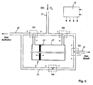
- FIG. 6 shows a catheter 28 having an elongated, flexible tube 29 and an over a bend 30 angled outflow end 31.
- sensors 32, 33 for detecting the spontaneous breathing of a patient P are attached.
- the sensors 32, 33 are preferably thermistors.
- the presentation of data lines has been omitted for the sake of simplicity. These pass through the catheter 28 or the catheter wall. With 34 a stop is designated.
- the end 31 of the catheter 28 is provided with a jet nozzle 35.
- the jet nozzle 35 the flow cross section with respect to the cross section of the catheter is reduced, so that the supplied oxygen is increased in the exit velocity.
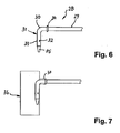
- the catheter 28 may be inserted into a support body 36, as in FIG FIG. 7 shown to be introduced.
- the support body 35 is located in the trachea of a patient P.
- the connection to the outside is made via a connection 37
- the support body 36 may be a conventional "Montgomery T stent".
Description
Die Erfindung betrifft eine Anordnung zur Atmungsunterstützung eines Patienten.The invention relates to an arrangement for the respiratory assistance of a patient.
Damit der Körper Sauerstoff aufnehmen und Kohlendioxid abgeben kann, müssen beide Komponenten des respiratorischen Bronchialsystems funktionieren. Die Lunge als gasaustauschendes Organ und die Atempumpe als Ventilationsorgan, welches die Luft in die Lunge hinein und wieder hinaus transportiert. Zur korrekten Funktion der Atempumpe gehören das Atemzentrum im Gehirn, zentrale und periphere Nerven, der knöcherne Thorax und die Atemmuskulatur sowie freie, stabile Atemwege.For the body to absorb oxygen and release carbon dioxide, both components of the respiratory bronchial system must function. The lung as a gas-exchanging organ and the respiratory pump as a ventilation organ, which transports the air into and out of the lungs. The correct function of the breathing pump includes the respiratory center in the brain, central and peripheral nerves, the bony thorax and the respiratory muscles as well as free, stable airways.
Bei bestimmten Erkrankungen besteht eine dauerhafte Überbeanspruchung oder Erschöpfung der Atempumpe. Ein typisches Krankheitsbild ist das Lungenemphysem mit flach stehenden Zwerchfellen ohne Kontraktionsfähigkeit. Bei einem Lungenemphysem sind die Atemwege meistens extrem schlaff und kollaptisch. In Folge der abgeflachten, überdehnten Zwerchfelle kann der Patient nicht tief genug einatmen. Zusätzlich kann der Patient aufgrund der kollabierenden Atemwege nicht ausreichend genug ausatmen. Dies führt zu einer unzureichenden Atmung mit Sauerstoffunterversorgung und einem Anstieg des Kohlendioxids im Blut, zur so genannten ventilatorischen Insuffizienz.In certain diseases there is a permanent overuse or exhaustion of the breathing pump. A typical clinical picture is pulmonary emphysema with flat diaphragms without contractility. At a In pulmonary emphysema, the airways are usually extremely limp and collapsing. As a result of the flattened, overstretched diaphragm, the patient can not breathe deeply enough. In addition, due to the collapsing airway, the patient can not exhale sufficiently. This leads to insufficient breathing with oxygen deficiency and an increase in carbon dioxide in the blood, called ventilatory insufficiency.
Die Behandlung der Einatmungsschwäche erfolgt oft über ein Beatmungsgerät. Die so genannte Heimbeatmung ist eine künstliche Beatmung zur Unterstützung oder vollständigen Entlastung der Atempumpe.The treatment of inhalation weakness is often via a ventilator. The so-called home ventilation is an artificial respiration to support or completely relieve the respiratory pump.
Die Beatmung kann nicht-invasiv erfolgen über einen Schlauch und eine Nasen- oder Mund/Nasenmaske, die der Patient bei Bedarf selbst auf- und absetzen kann. Hierdurch wird jedoch die freie Atmung und das Sprechen des Patienten behindert. Des Weiteren kann eine geblockte Trachealkanüle in die Luftröhre eingesetzt werden. Auch dies hat zur Folge, dass der Patient nicht mehr sprechen kann.Ventilation can be non-invasive via a tube and nasal or oral / nasal mask, which the patient can put on and off himself when needed. However, this hinders free breathing and speaking of the patient. Furthermore, a blocked tracheostomy tube can be inserted into the trachea. This also means that the patient can no longer speak.
Bei der invasiven Beatmung geschieht dies meistens über ein Tracheostoma. Hierbei handelt es sich um eine operativ angelegte Öffnung in der Luftröhre. Über die Öffnung wird ein fingerdicker Katheter mit einem Blockungsballon in die Luftröhre eingeführt und dieser an ein Beatmungsgerät angeschlossen. Dies ermöglicht eine ausreichend tiefe Atmung, hindert den Patienten aber am Sprechen. Neben der Beatmung gibt es die transtracheale Sauerstoffgabe über dünnere Katheter. Entsprechende Vorschläge gehen aus der
Dokument
Bekannt sind ferner so genannte "Montgomery-T-Röhrchen", die in die Luftröhre eingelegt werden. Hierüber kann der Patient über den nach außen geleiteten Schenkel des T-Stücks Sauerstoff erhalten. Ferner kann sich der Patient im Bedarfsfall selber Sekret absaugen. Der Patient kann frei atmen und bei Verschluss des vorderen Schenkels sprechen, eine Beatmung ist über das "Montgomery-T-Röhrchen" aber nicht möglich, da die eingeleitete Luft nach oben in den Mund- oder Rachenraum ausweicht.Also known are so-called "Montgomery T-tubes", which are inserted into the trachea. This allows the patient to receive oxygen via the outwardly directed leg of the T-piece. Furthermore, if necessary, the patient can aspirate secretions himself. The patient can breathe freely and speak when closing the front leg, ventilation via the "Montgomery T-tube" but not possible because the air introduced escapes up into the mouth or throat.
Der Erfindung liegt daher ausgehend vom Stand der Technik die Aufgabe zugrunde, eine verbesserte Anordnung zur Atmungsunterstützung eines Patienten zu schaffen, die sicher in der Anwendung ist. Es werden auch eine Luftröhrenprothese und einen Katheter beschrieben, die eine mit der Spontanatmung des Patienten synchronisierte Atmungsunterstützung ermöglichen, ohne die Sprechfähigkeit zu beeinträchtigen.The invention is therefore based on the object of the prior art to provide an improved arrangement for the respiratory assistance of a patient who is safe in the application. Also described are a tracheal prosthesis and a catheter that provide respiratory support synchronized with spontaneous breathing of the patient without compromising speech ability.
Die Lösung des verfahrensmäßigen Teils der Aufgabe besteht in einer Anordnung nach dem Patentanspruch 1.The solution of the procedural part of the task consists in an arrangement according to
Bei einer Anwendung der Anordnung wird die Spontanatmung des Patienten sensorisch erfasst und am Ende eines Einatmungsvorgangs der Lunge eine zusätzliche Sauerstoffmenge verabreicht. Dies kann in Form eines Sauerstoffstoßes über einen Jet-Katheter aus einem Sauerstoffreservoir erfolgen. Hierbei erfolgt eine Synchronisation der Atmungsunterstützung mit der natürlichen Atmung eines Patienten. Auf diese Weise wird die infolge einer Überbeanspruchung oder Erschöpfung der Atempumpe verminderte Atemtiefe kompensiert. Die Atmung wird durch die zusätzliche Sauerstoffmenge auf einem ausreichenden Niveau gehalten. Eine Sauerstoffunterversorgung und der Anstieg von Kohlendioxid im Blut wird vermieden.In one application of the arrangement, the spontaneous breathing of the patient is sensory detected and administered at the end of an inhalation process of the lungs an additional amount of oxygen. This can be done in the form of a burst of oxygen via a jet catheter from an oxygen reservoir. In this case, a synchronization of the respiratory support with the natural respiration of a patient. In this way, the reduced breathing depth due to overuse or exhaustion of the breathing pump is compensated. Breathing is kept at a sufficient level by the additional amount of oxygen. An oxygen deficiency and the increase of carbon dioxide in the blood is avoided.
Zweckmäßigerweise hat die zusätzliche Sauerstoffmenge ein Volumen zwischen 25 ml bis 150 ml.Conveniently, the additional amount of oxygen has a volume between 25 ml to 150 ml.
Wahlweise kann bei Bedarf der Ausatmungsvorgang des Patienten durch einen Gegenstrom gebremst werden. Dies ist immer dann empfehlenswert, wenn die Atemwege des Patienten kollaptisch sind, also im Augenblick des Ausatmungsvorgangs zusammenfallen, wodurch der Ausatmungsvorgang extrem behindert werden kann. Dies kann dadurch verhindert werden, dass während der Ausatmung ein Gegenstrom aufgebracht wird, wodurch die Atemwege offen gehalten und ein Kollaps der Atemwege vermieden wird.Optionally, if necessary, the exhalation process of the patient can be slowed down by a counterflow. This is always recommended when the patient's respiratory system is collapsible, ie at the moment of exhalation coincide, whereby the exhalation process can be extremely impeded. This can be avoided by counterflowing during exhalation, keeping the airway open and avoiding airway collapse.
Die erfinderische Anordnung sieht eine an eine Sauerstoffquelle anschließbare Sauerstoffpumpe und eine Luftröhrenprothese vor, die über einen Katheter gegebenenfalls unter weiterer Verwendung eines Zuführschlauchs verbindbar sind. Das ausströmseitige Ende des Katheters wirkt einen Düsencharakter auf den Sauerstoffstrom aus. Dies kann beispielsweise durch eine Querschnittsverringerung erfolgen. Grundsätzlich kann das Ende des Katheters auch mit einer Jet-Düse versehen sein. Ferner sind Sensoren vorgesehen zur Erfassung der Spontanatmung des Patienten, die mit einer Steuereinheit zur Aktivierung der Sauerstoffpumpe verknüpft sind. Die Luftröhrenprothese weist einen tubulären Stützkörper mit einem Anschluss für den Katheter auf. Der Stützkörper und der integrierte Katheter sind so dimensioniert, dass der Patient ungehindert frei atmen und sprechen kann. Die Hauptatmung erfolgt durch das größere Innenlumen der Luftröhrenprothese. Die Spontanatmung, Husten und Sprechen werden nicht behindert. Ferner sind am Stützkörper zumindest zwei der zur Anordnung gehörenden Sensoren vorgesehen.The inventive arrangement provides an oxygen pump which can be connected to an oxygen source and a tracheal prosthesis which can be connected via a catheter, optionally with the use of a supply tube. The outflow end of the catheter exerts a nozzle character on the oxygen flow. This can be done for example by a cross-sectional reduction. In principle, the end of the catheter can also be provided with a jet nozzle. Furthermore, sensors are provided for detecting the spontaneous breathing of the patient, which are linked to a control unit for activating the oxygen pump. The tracheal prosthesis has a tubular support body with a port for the catheter. The support body and the integrated catheter are dimensioned so that the patient can freely breathe freely and speak. The main respiration occurs through the larger inner lumen of the tracheal prosthesis. Spontaneous breathing, coughing and speech are not hindered. Furthermore, at least two of the sensors belonging to the arrangement are provided on the support body.
Die Luftröhrenprothese wird in die Luftröhre eines Patienten implantiert. Über einen kleinen Luftröhrenschnitt wird der Zugang für den Katheter nach außen geschaffen. Der Katheter kann über den Anschluss mit einem Ende direkt in den Stützkörper geführt werden. Möglich ist es auch, den Katheter außen über eine Kupplung mit dem Anschluss zu verbinden.The tracheal prosthesis is implanted in the trachea of a patient. A small tracheotomy creates access for the catheter to the outside. The catheter can be guided via the connection with one end directly into the support body. It is also possible to connect the catheter externally via a coupling with the connection.
Die Sensoren dienen zur Erfassung der Spontanatmung des Patienten. Es können verschiedenartige A temfühler, beispielsweise A temfluss-Sensoren o der Druckfühler zur Anwendung gelangen. Besonders vorteilhaft sind Thermistoren. Hierbei handelt es sich um Halbleiterbauelemente mit temperaturabhängigem Widerstand. Die Temperaturabhängigkeit der Widerstände wird zur Erfassung der Ein- bzw. Ausatmungsvorgänge genutzt da die Ausatemluft der Lunge in der Luftröhre naturgemäß wärmer ist als die Einatemluft.The sensors are used to detect the spontaneous breathing of the patient. Various temperature sensors, for example, flow sensors or the pressure sensors can be used. Particularly advantageous are thermistors. These are semiconductor devices with temperature-dependent resistance. The temperature dependence of the resistors is used to detect the on or Ausatmungsvorgänge used since the exhaled air of the lungs in the trachea is naturally warmer than the inhaled air.
In vorteilhafter Weise ist gemäß den Merkmalen von Patentanspruch 4 ein Sensor an der Innenwand des Stützkörpers festgelegt. Der andere Sensor ist dann an der Außenwand des Stützkörpers angeordnet oder im Stützkörper selbst eingebettet.Advantageously, according to the features of claim 4, a sensor is fixed to the inner wall of the support body. The other sensor is then arranged on the outer wall of the support body or embedded in the support body itself.
Über eine Brückenschaltung erfolgt eine Kompensation der aufgenommenen Messwertunterschiede zwischen dem innenliegenden und dem außenliegenden Sensor. Durch diese Doppelanordnung können Umwelteinflüsse, wie Temperaturschwankungen und ähnliches ausgeglichen werden.By means of a bridge circuit, the recorded measured value differences between the internal and the external sensor are compensated. By this double arrangement environmental influences, such as temperature fluctuations and the like can be compensated.
Nach den Merkmalen von Patentanspruch 5 ist das im Stützkörper befindliche Ende des Katheters im Wesentlichen parallel zu dessen Längsachse umgelenkt und endseitig mit einer Jet-Düse versehen. Hierbei kann es sich um eine separate Düse handeln. Die Jet-Düse kann aber auch in Form einer Querschnittsverringerung am Ende des Katheters gestaltet sein. Auf diese Weise kann der über den Katheter eingeleitete Luft- bzw. Sauerstoffstrom in Richtung zur Lunge geleitet werden, und zwar mit einer laminaren Strömung. Ein Ausweichen des Sauerstoffs in den Mund- oder Rachenraum wird verhindert. Der das Katheterende bzw. das Endstück aufnehmende Stützkörper verhindert ein Austrocknen des umliegenden Gewebes. Zudem wird eine Traumatisierung der Luftröhre bzw. des Gewebes, beispielsweise in Folge von Bewegungen des Katheterendes, vermieden.According to the features of
Zweckmäßigerweise ist die Sauerstoffpumpe als Kolbenpumpe ausgeführt. Insbesondere bietet sich der Einsatz eines Zylinders mit doppelt wirkendem Kolben oder verschieblicher Membran an. Eine solche Sauerstoffpumpe zeichnet sich durch ihre kompakte Bauweise aus. Zudem ist eine zuverlässige Einstellung der aufgegebenen Sauerstoffmenge möglich, und zwar sowohl für die Unterstützung des Einatmungsvorgangs als auch die des Ausatmungsvorgangs. Da die maximale Luftmenge pro Jet-Hub durch die Zylindergöße begrenzt ist, kann auch ein Überblähen der Lunge mit der Folge eines Baro-Traumas vermieden werden.Conveniently, the oxygen pump is designed as a piston pump. In particular, the use of a cylinder with double-acting piston or displaceable membrane offers. Such an oxygen pump is characterized by its compact design. In addition, a reliable adjustment of the amount of oxygen given is possible, both for the support of the inhalation process and the exhalation process. Since the maximum amount of air per jet stroke is limited by the cylinder size, also an over-swelling of the lung with the consequence of a baro-trauma can be avoided.
Im Rahmen der erfindungsgemäßen Anordnung können zwei Katheter zur Anwendung gelangen, wobei ein Jet-Katheter für die Unterstützung des Einatmungsvorgangs und der andere Katheter für das gezielte Abbremsen des Ausatmungsvorgangs vorgesehen ist. Selbstverständlich kann auch ein Katheter doppellumig ausgeführt sein, wie dies Patentanspruch 7 vorsieht. Über den doppellumigen Katheter werden getrennte Kanäle für die Verabreichung von Sauerstoff beim Einatmungsvorgang und beim Ausatmungsvorgang bereitgestellt.In the context of the inventive arrangement, two catheters can be used, wherein a jet catheter for supporting the Inhalation process and the other catheter for the targeted braking of the exhalation process is provided. Of course, a catheter can be designed with double lobes, as provided by claim 7. The dual-lumen catheter provides separate channels for the delivery of oxygen during the inhalation and exhalation procedures.
Eine Sicherheitssteigerung der Anordnung wird erzielt, wenn weitere Atemfühler vorgesehen sind. Auch hierbei handelt es sich um Sensoren zur Erfassung der Spontanatmung eines Patienten. Diese können beispielsweise am Brustkorb des Patienten befestigt werden, so dass die Spontanatmung durch eine Thoraximpedanz-Messung überwacht werden kann. Denkbar ist auch eine Schall- oder Flussmessung an Mund oder Nase des Patienten. Durch Abgleich der aufgenommenen Signale aus der Luftröhre und der weiteren Atemfühler in einer Steuer- und Kontrolleinheit und entsprechende Ansteuerung der Sauerstoffpumpe wird die Einatmungs- bzw. Ausatmungsunterstützung durchgeführt. Die zusätzlichen Atemfühler gewährleisten eine redundante Ausführung und tragen zur Sicherheit der Anordnung bei.An increase in safety of the arrangement is achieved if additional breathing sensors are provided. Again, these are sensors for detecting the spontaneous breathing of a patient. These can for example be attached to the chest of the patient, so that the spontaneous breathing can be monitored by a chest impedance measurement. Also conceivable is a sound or flow measurement at the mouth or nose of the patient. By balancing the recorded signals from the trachea and the other breath sensor in a control and monitoring unit and corresponding control of the oxygen pump, the inhalation and exhalation support is performed. The additional breathing sensors ensure a redundant design and contribute to the safety of the arrangement.
Eine zur Anwendung mit der Anordnung nach Anspruch 1 geeignete Luftröhrenprothese weist einen tubulären Stützkörper mit einem Anschluss für einen Katheter auf, wobei am Stützkörper zumindest zwei Sensoren angeordnet sind. Die Luftröhrenprothese zeichnet sich dadurch aus, dass mit ihr die Atmung eines Patienten messbar ist. Auf diese Weise ist eine Synchronisation der externen Atmungsunterstützung mit der Eigenatmung des Patienten möglich.A tracheal prosthesis suitable for use with the device according to
In vorteilhafter Weise i st ein Sensor an der Innenwand des Stützkörpers befestigt. Als besonders geeignet werden im Rahmen der Erfindung. Thermistoren angesehen. Durch Zusammenfassung der Thermistoren in einer Brückenschaltung kann eine Kompensation der Temperatur zwischen dem innen liegenden und einem außen liegenden Thermistor erfolgen. Diese Doppelanordnung der Sensoren in der Brückenschaltung kompensiert Umwelteinflüsse, wie Temperaturschwankungen oder auch solche, die durch Sekret hervorgerufen werden, welches sich am inneren Sensor auflegt und eine lokale Abkühlung oder Erwärmung bedingt.Advantageously, a sensor is attached to the inner wall of the support body. Be particularly suitable in the context of the invention. Thermistors viewed. By combining the thermistors in a bridge circuit, a compensation of the temperature between the inner and an outer thermistor can take place. This double arrangement of the sensors in the bridge circuit compensates for environmental influences, such as temperature fluctuations or those caused by secretion, which hangs up on the inner sensor and causes a local cooling or heating.
Vorteilhaft ist ferner, wenn das Katheterende im Stützkörper parallel zu dessen Längsachse geführt ist. Hierdurch erfolgt eine gerichtete Aufgabe der Sauerstoffströme in Richtung zum Bronchialtrakt, und zwar mit laminaren Strömungsverhältnissen.It is also advantageous if the catheter end is guided in the support body parallel to its longitudinal axis. As a result, there is a directed task of the oxygen streams in the direction of the bronchial tract, with laminar flow conditions.
An dem ausströmseitigen Ende des Katheters ist zumindest ein Sensor befestigt. Zweckmäßigerweise sind dort zwei Sensoren vorgesehen, um innerhalb einer Brückenschaltung eine Kompensation von Messwertunterschieden durchführen zu können.At least one sensor is attached to the outflow end of the catheter. Expediently, two sensors are provided there in order to be able to carry out a compensation of measured value differences within a bridge circuit.
Ein solcher Katheter kann von außen in einen Stützkörper eingeführt werden. B ei einem solchen Stützkörper kann es sich beispielsweise um einen bekannten "Montgomery-T-Stent" handeln. Über den von außen zugängigen Schenkel des T-Stücks wird der Katheter eingeführt, um darüber die Atmung zu unterstützen.Such a catheter can be introduced from the outside into a support body. Such a support body may be, for example, a known "Montgomery T stent". The externally accessible leg of the T-piece is used to insert the catheter to aid in breathing.
Nach den Merkmalen von Patentanspruch 10 weist das Ende des Katheters eine Jet-Düse auf. Diese ist, wie bereits weiter oben beschrieben, beispielsweise durch eine Querschnittsverengung des Endes ausgeführt. Es kann sich aber auch um eine separate Jet-Düse handeln.According to the features of
Vorteilhafterweise ist das Ende des Katheters gekrümmt ausgeführt. Auf diese Weise ist das in die Luftröhre bzw. den Stützkörper eingeführte Ende selbsttätig in Richtung zum Bronchialtrakt parallel zur Längsachse des Stützkörpers ausgerichtet.Advantageously, the end of the catheter is curved. In this way, the inserted into the trachea or the supporting body end is automatically aligned in the direction of the bronchial tract parallel to the longitudinal axis of the support body.
Die Erfindung ist nachfolgend anhand der beigefügten Zeichnungen näher beschrieben. Es zeigen:
Figur 1- den Oberkörper eines Patienten, der eine erfindungsgemäße Anordnung zur Atmungsunterstützung trägt;
- Figur 2
- ein Diagramm mit der Darstellung des Atemflusses eines Emphysem-Patienten mit und ohne Atmungsunterstützung;
Figur 3- eine technisch vereinfachte Darstellung einer Luftröhrenprothese;
- Figur 4
- ein weiteres Beispiel einer Luftröhrenprothese;
Figur 5- ebenfalls im Schema eine zur erfindungsgemäßen Anordnung gehörende Sauerstoffpumpe mit der Darstellung der Luftführung und einer Steuereinheit;
Figur 6- den endseitigen Ausschnitt aus einem Katheter und
- Figur 7
- den Katheter gemäß der
Figur 6 in einem Stützkörper eingesetzt.
- FIG. 1
- the upper body of a patient wearing an inventive arrangement for respiratory support;
- FIG. 2
- a diagram showing the respiratory flow of an emphysema patient with and without respiratory support;
- FIG. 3
- a technically simplified representation of a tracheal prosthesis;
- FIG. 4
- another example of a tracheal prosthesis;
- FIG. 5
- also in the scheme belonging to the inventive arrangement oxygen pump with the representation of the air duct and a control unit;
- FIG. 6
- the end-side cutout of a catheter and
- FIG. 7
- the catheter according to the
FIG. 6 used in a support body.
In der
Ein solcher Atmungsvorgang mit Einatmung (Inspiratorischer Fluss) und Ausatmung (Exspiratorischer Fluss) ohne Atmungsunterstützung ist in der
Zur Unterstützung bzw. Entlastung der Atempumpe wird bei dem Patienten die Spontanatmung sensorisch erfasst und am Ende eines Einatmungsvorgangs der Lunge eine zusätzliche Sauerstoffmenge verabreicht. Dieser Atemfluss ist in der
Zusätzlich wird der Ausatmungsvorgang des Patienten durch einen Gegenstrom gebremst. Hierdurch verlagert sich der Atemfluss bei der Ausatmung entsprechend der mit A2 bezeichneten Kurve. Durch diesen gezielten der Ausatmung entgegengesetzt wirkenden Widerstand wird ein Kollabieren der Atemwege beim Ausatmen verhindert. Auf diese Weise wird das Ausatemvolumen um das ebenfalls dunkel angelegte und mit A3 bezeichnete Volumen vergrößert.In addition, the exhalation process of the patient is slowed down by a counterflow. As a result, the respiratory flow during exhalation shifts according to the curve designated A2. This targeted counter-exertion resistance prevents airway collapse when exhaling. In this way, the expiratory volume is increased by the likewise dark-based and designated A3 volume.
In der Konsequenz wird durch diese Vorgehensweise eine unzureichende Atmung mit Sauerstoffunterversorgung und ein Anstieg von Kohlendioxid im Blut vermieden. Der Patient P ist wesentlich belastbarer und mobiler, zudem verspürt er weniger oder keine Luftnot.As a result, this approach avoids inadequate respiration with oxygen deficiency and an increase in carbon dioxide in the blood. The patient P is much more resilient and mobile, moreover, he feels less or no air distress.
Zur Durchführung der Atmungsunterstützung des Patienten P ist eine Anordnung vorgesehen, welche eine an eine Sauerstoffquelle anschließbare Sauerstoffpumpe 1 (siehe
Wie die
Ferner erkennt man in der
Bei der Luftröhrenprothese 2 gemäß
Bei der Luftröhrenprothese 3 gemäß
Die Sauerstoffpumpe 1 ist in der
Bei der Atmungsunterstützung ist die Funktion der Sauerstoffpumpe 1 innerhalb der Anordnung wie folgt:
- Wenn das Ventil V1 von c nach a offen (b nach c geschlossen) und das Ventil V2 von b nach e offen (e nach d geschlossen) ist, bewegt sich der
Kolben 20 in Bildebene nach links und der Sauerstoff strömt überden Auslass 22 und den Jet-Katheter 5 zum Patienten P. Es erfolgt die Verabreichung der zusätzlichen Sauerstoffmenge E3 beim Einatmungsvorgang des Patienten P. - Wenn das Ventil V1 von b nach c (c nach a geschlossen) offen und das Ventil V2 von e nach d offen (b nach e geschlossen) ist, dann bewegt sich der
Kolben 20 in Bildebene nach rechts und die Strömung des Sauerstoffs erfolgt in Richtung zum Ventil V3. Das Ventil V3 steht über einen Auslass 23 mit der Umluft in Verbindung. Im Fall, dass das Ventil V3 von d nach g offen ist, strömt der Sauerstoff ab ohne Exspirationsbremse. Das bedeutet, der Ausatmungsvorgang wird nicht durch einen Gegenstrom gebremst.
- When the valve V1 is open from c to a (b closed to c) and the valve V2 is open from b to e (e to d), the
piston 20 moves to the left in the image plane and the oxygen flows through theoutlet 22 and thejet catheter 5 to the patient P. The additional amount of oxygen E3 is administered during the inhalation process of the patient P. - When the valve V1 is open from b to c (c closed to a) and the valve V2 is open from e to d (b closed to e), then the
piston 20 moves in Image plane to the right and the flow of oxygen takes place in the direction of valve V3. The valve V3 is connected via anoutlet 23 with the circulating air. In the case that the valve V3 is open from d to g, the oxygen flows off without expiratory brake. This means that the exhalation process is not slowed down by a counterflow.
Ist das Ventil V3 von d nach g geschlossen und von d nach f offen, strömt der Sauerstoff in Richtung über den Zuweg 24 zum Auslass 22 und den Katheter 5, um dem Patienten P beim Ausatmungsvorgang verabreicht zu werden und den Atemfluss zu bremsen. Durch den Gegenstrom wird ein Kollabieren der Atemwege verhindert und diese offen gehalten. Dies ermöglicht eine tiefere Ausatmung.When the valve V3 is closed from d to g and open from d to f, the oxygen flows toward the
Im Zuweg 24 der Anordnung ist ferner das Ventil V4 geschaltet, über welches der Durchfluss (f nach a) variabel einstellbar ist. Dies kann vorteilhafterweise ein Proportionalventil mit Pulsbreitenmodulation sein.In the
Die
Ferner erkennt man, dass das Ende 31 des Katheters 28 mit einer Jet-Düse 35 versehen ist. In der Jet-Düse 35 ist der Strömungsquerschnitt gegenüber dem Querschnitt des Katheters verringert, so dass der zugeführte Sauerstoff in der Austrittsgeschwindigkeit erhöht wird.Furthermore, it can be seen that the
Der Katheter 28 kann in einen Stützkörper 36, wie in
Bei dem Stützkörper 36 kann es sich um einen herkömmlichen "Montgomery-T-Stent" handeln.The
- 1 -1 -
- Sauerstoffpumpeoxygen pump
- 2 -2 -
- LuftröhrenprotheseAirway prosthesis
- 3 -3 -
- LuftröhrenprotheseAirway prosthesis
- 4 -4 -
- Beatmungsgerätventilator
- 5 -5 -
- -Katheter-Catheter
- 6 -6 -
- Stützkörpersupport body
- 7 -7 -
- Anschlussconnection
- 8 -8th -
- Sensorsensor
- 9 -9 -
- Sensorsensor
- 10 -10 -
- Innenwand v. 6Inner wall v. 6
- 11 -11 -
- Außenwand v. 6Outside wall v. 6
- 12 -12 -
- Steuereinheitcontrol unit
- 13 -13 -
- Atemfühlerrespiratory sensor
- 14 -14 -
- Atemfühlerrespiratory sensor
- 15 -15 -
- Ende v. 5End of v. 5
- 16 -16 -
- Datenleitungdata line
- 17 -17 -
- Datenleitungdata line
- 18 -18 -
- Kupplungclutch
- 19 -19 -
- Längenabschnittlongitudinal section
- 20 -20 -
- Kolbenpiston
- 21 -21 -
- Anschlussconnection
- 22 -22 -
- Auslassoutlet
- 23 -23 -
- Auslassoutlet
- 24 -24 -
- Zuwegfeeder path
- 25 -25 -
- Jet-DüseJet Nozzle
- 26 -26 -
- Jet-DüseJet Nozzle
- 27 -27 -
- Zylindercylinder
- 28 -28 -
- Kathetercatheter
- 29 -29 -
- Schlauchtube
- 30 -30 -
- Krümmungcurvature
- 31 -31 -
- Ende v. 28End of v. 28
- 32 -32 -
- Sensorsensor
- 33 -33 -
- Sensorsensor
- 34 -34 -
- Anschlagattack
- 35 -35 -
- Jet-DüseJet Nozzle
- 36 -36 -
- Stützkörpersupport body
- 37 -37 -
- Anschlussconnection
- P -P -
- Patientpatient
- E1 -E1 -
- Einatmungskurverespirable
- E2 -E2 -
- Einatmungskurverespirable
- E3 -E3 -
- Volumenvolume
- A1 -A1 -
- AusatmungskurveAusatmungskurve
- A2 -A2 -
- AusatmungskurveAusatmungskurve
- A3 -A3 -
- Volumenvolume
- V1 -V1 -
- VentilValve
- V2 -V2 -
- VentilValve
- V3 -V3 -
- VentilValve
- V4 -V4 -
- VentilValve
- L -L -
- Längsachse v. 5Longitudinal axis v. 5
- a -a -
- Leitungmanagement
- b -b -
- Leitungmanagement
- c -c -
- Leitungmanagement
- d -d -
- Leitungmanagement
- e -e -
- Leitungmanagement
- f -f -
- Leitungmanagement
- g -g -
- Leitungmanagement
Claims (13)
- Arrangement for respiratory support for a patient with spontaneous breathing, the arrangement comprising the following:a) an oxygen pump (1) for connection to an oxygen source;b) a tracheal catheter (5, 28) having a first end which is connected to the oxygen pump (1) and a second end for transtracheal insertion into the trachea of a patient, which is dimensioned such that spontaneous breathing and speech are not impeded in use;c) at least one sensor (8, 9, 32, 33) for insertion in the trachea of the patient for detecting the spontaneous breathing of the patient, andd) a control unit (12), connected to the at least one sensor, for activating the oxygen pump (1) in order to deliver an additional quantity of oxygen to the patient,characterised in that
the control unit connected to at least one sensor is configured to deliver the additional oxygen synchronously with the spontaneous breathing of the patient. - Arrangement according to Claim 1, which also includes a tracheal prosthesis (2, 3) having a tubular support body (6), wherein the support body (6) has a connection (7) for the catheter.
- Arrangement according to Claim 2, wherein the at least one sensor (8, 9) is provided on the support body (6).
- Arrangement according to Claim 3, wherein one of the at least one sensors (8) is fastened against the inner wall (10) of the support body (6).
- Arrangement according to any one of Claims 2 to 4, wherein the second end (15) of the catheter (5) is located inside the support body (6) and is oriented in such a way that it is located approximately parallel to the longitudinal axis (L) of the support body (6) and is provided at its end with a jet nozzle.
- Arrangement according to any one of Claims 1 to 5, wherein the oxygen pump (1) is a piston pump.
- Arrangement according to any one of Claims 1 to 6, wherein the catheter has a double lumen.
- Arrangement according to any one of Claims 1 to 7, wherein one of the sensors (32, 33) is arranged at the second end of the catheter.
- Arrangement according to any one of Claims 1 to 8, wherein further breathing sensors (13, 14) are provided additionally to the at least one sensor (8, 9, 32, 33).
- Arrangement according to any one of Claims 1 to 9, wherein the catheter (5) has a jet nozzle and the cross section of the jet nozzle is smaller than the cross section of the catheter, so that the volume flow rate of the oxygen delivered is increased.
- Arrangement according to each of claims 1 to 10, wherein the sensor consists of a pair of thermistors.
- Arrangement according to Claim 11, wherein the thermistors are connected in a bridge circuit in order to compensate for environmental influences.
- Arrangement according to Claim 1, wherein said at least one sensor comprises two sensors (8, 9).
Applications Claiming Priority (2)
| Application Number | Priority Date | Filing Date | Title |
|---|---|---|---|
| DE10337138A DE10337138A1 (en) | 2003-08-11 | 2003-08-11 | Method and arrangement for the respiratory assistance of a patient as well as tracheal prosthesis and catheter |
| PCT/DE2004/001646 WO2005014091A2 (en) | 2003-08-11 | 2004-07-23 | Method and arrangement for respiratory support for a patient airway prosthesis and catheter |
Publications (2)
| Publication Number | Publication Date |
|---|---|
| EP1654023A2 EP1654023A2 (en) | 2006-05-10 |
| EP1654023B1 true EP1654023B1 (en) | 2014-07-16 |
Family
ID=34129567
Family Applications (1)
| Application Number | Title | Priority Date | Filing Date |
|---|---|---|---|
| EP04762494.5A Active EP1654023B1 (en) | 2003-08-11 | 2004-07-23 | Arrangement for respiratory support for a patient |
Country Status (7)
| Country | Link |
|---|---|
| US (5) | US7487778B2 (en) |
| EP (1) | EP1654023B1 (en) |
| JP (1) | JP4931586B2 (en) |
| CN (2) | CN1867371B (en) |
| CA (1) | CA2535450C (en) |
| DE (1) | DE10337138A1 (en) |
| WO (1) | WO2005014091A2 (en) |
Families Citing this family (91)
| Publication number | Priority date | Publication date | Assignee | Title |
|---|---|---|---|---|
| US7089941B2 (en) * | 2002-08-20 | 2006-08-15 | Bordewick Steven S | Face mask support |
| US7845353B2 (en) * | 2002-08-20 | 2010-12-07 | Aeiomed, Inc. | Face mask support |
| US8381729B2 (en) * | 2003-06-18 | 2013-02-26 | Breathe Technologies, Inc. | Methods and devices for minimally invasive respiratory support |
| DE10337138A1 (en) * | 2003-08-11 | 2005-03-17 | Freitag, Lutz, Dr. | Method and arrangement for the respiratory assistance of a patient as well as tracheal prosthesis and catheter |
| US7588033B2 (en) * | 2003-06-18 | 2009-09-15 | Breathe Technologies, Inc. | Methods, systems and devices for improving ventilation in a lung area |
| FR2858236B1 (en) * | 2003-07-29 | 2006-04-28 | Airox | DEVICE AND METHOD FOR SUPPLYING RESPIRATORY GAS IN PRESSURE OR VOLUME |
| JP2007506480A (en) | 2003-08-18 | 2007-03-22 | ワンドカ,アンソニー・ディ | Methods and apparatus for non-invasive ventilation with a nasal interface |
| DE102004019122A1 (en) * | 2004-04-16 | 2005-11-10 | Universitätsklinikum Freiburg | Method for controlling a ventilator and installation therefor |
| EP1926517A2 (en) * | 2005-09-20 | 2008-06-04 | Lutz Freitag | Systems, methods and apparatus for respiratory support of a patient |
| WO2007062400A2 (en) | 2005-11-23 | 2007-05-31 | Jianguo Sun | Method and apparatus for providing positive airway pressure to a patient |
| BRPI0709500A2 (en) | 2006-04-10 | 2011-07-26 | Aeiomed Inc | apparatus for providing positive airway pressure for the treatment of sleep apnea, chronic pulmonary obstruction and snoring, and method for providing positive air pressure for the treatment of sleep apnea, chronic pulmonary obstruction and snoring |
| EP2010260A1 (en) | 2006-04-10 | 2009-01-07 | AEIOMed, Inc. | Apparatus and methods for providing humidity in respiratory therapy |
| CN101541365A (en) | 2006-05-18 | 2009-09-23 | 呼吸科技公司 | Tracheostoma tracheotomy method and device |
| WO2007149446A2 (en) * | 2006-06-16 | 2007-12-27 | Aeiomed, Inc. | Modular positive airway pressure therapy apparatus and methods |
| US9010327B2 (en) * | 2006-06-30 | 2015-04-21 | Breas Medical Ab | Energy relief control in a mechanical ventilator |
| WO2008005578A2 (en) * | 2006-07-07 | 2008-01-10 | Aeiomed, Inc. | Composite masks and methods for positive airway pressure therapies |
| US8020558B2 (en) * | 2007-01-26 | 2011-09-20 | Cs Medical, Inc. | System for providing flow-targeted ventilation synchronized to a patient's breathing cycle |
| US9586018B2 (en) | 2007-01-26 | 2017-03-07 | Cs Medical, Inc. | System for providing flow-targeted ventilation synchronized to a patients breathing cycle |
| WO2008144589A1 (en) * | 2007-05-18 | 2008-11-27 | Breathe Technologies, Inc. | Methods and devices for sensing respiration and providing ventilation therapy |
| JP2010531685A (en) * | 2007-06-29 | 2010-09-30 | マーメイド ケア アクティーゼルスカブ | Gas mixing device for airway maintenance system |
| US20090078255A1 (en) * | 2007-09-21 | 2009-03-26 | Bowman Bruce R | Methods for pressure regulation in positive pressure respiratory therapy |
| US20090078258A1 (en) * | 2007-09-21 | 2009-03-26 | Bowman Bruce R | Pressure regulation methods for positive pressure respiratory therapy |
| US8567399B2 (en) | 2007-09-26 | 2013-10-29 | Breathe Technologies, Inc. | Methods and devices for providing inspiratory and expiratory flow relief during ventilation therapy |
| JP5513392B2 (en) | 2007-09-26 | 2014-06-04 | ブリーズ・テクノロジーズ・インコーポレーテッド | Method and apparatus for treating sleep apnea |
| US8770193B2 (en) | 2008-04-18 | 2014-07-08 | Breathe Technologies, Inc. | Methods and devices for sensing respiration and controlling ventilator functions |
| WO2009151791A2 (en) | 2008-04-18 | 2009-12-17 | Breathe Technologies, Inc. | Methods and devices for sensing respiration and controlling ventilator functions |
| US8181652B2 (en) * | 2008-05-22 | 2012-05-22 | Pierre Peron B | Infant positive pressure tracheal device |
| JP5715950B2 (en) | 2008-08-22 | 2015-05-13 | ブリーズ・テクノロジーズ・インコーポレーテッド | Method and apparatus for providing mechanical ventilation with an open airway interface |
| WO2010036816A1 (en) | 2008-09-25 | 2010-04-01 | Nellcor Puritan Bennett Llc | Inversion-based feed-forward compensation of inspiratory trigger dynamics in medical ventilators |
| US8302602B2 (en) | 2008-09-30 | 2012-11-06 | Nellcor Puritan Bennett Llc | Breathing assistance system with multiple pressure sensors |
| EP2344791B1 (en) * | 2008-10-01 | 2016-05-18 | Breathe Technologies, Inc. | Ventilator with biofeedback monitoring and control for improving patient activity and health |
| US8517017B2 (en) * | 2009-01-08 | 2013-08-27 | Hancock Medical, Inc. | Self-contained, intermittent positive airway pressure systems and methods for treating sleep apnea, snoring, and other respiratory disorders |
| US9132250B2 (en) | 2009-09-03 | 2015-09-15 | Breathe Technologies, Inc. | Methods, systems and devices for non-invasive ventilation including a non-sealing ventilation interface with an entrainment port and/or pressure feature |
| US8434479B2 (en) | 2009-02-27 | 2013-05-07 | Covidien Lp | Flow rate compensation for transient thermal response of hot-wire anemometers |
| EP4218876A1 (en) | 2009-04-02 | 2023-08-02 | Breathe Technologies, Inc. | Systems for non-invasive open ventilation with gas delivery nozzles within an outer tube |
| US9962512B2 (en) | 2009-04-02 | 2018-05-08 | Breathe Technologies, Inc. | Methods, systems and devices for non-invasive ventilation including a non-sealing ventilation interface with a free space nozzle feature |
| CN102762250B (en) | 2009-09-03 | 2017-09-26 | 呼吸科技公司 | Mthods, systems and devices for including the invasive ventilation with entrainment port and/or the non-tight vented interface of pressure characteristic |
| US8215302B2 (en) * | 2009-09-22 | 2012-07-10 | Kassatly L Samuel A | Discontinuous positive airway pressure device and method of reducing sleep disordered breathing events |
| US8469030B2 (en) * | 2009-12-01 | 2013-06-25 | Covidien Lp | Exhalation valve assembly with selectable contagious/non-contagious latch |
| US8469031B2 (en) * | 2009-12-01 | 2013-06-25 | Covidien Lp | Exhalation valve assembly with integrated filter |
| US8439036B2 (en) * | 2009-12-01 | 2013-05-14 | Covidien Lp | Exhalation valve assembly with integral flow sensor |
| US8439037B2 (en) | 2009-12-01 | 2013-05-14 | Covidien Lp | Exhalation valve assembly with integrated filter and flow sensor |
| US20110126832A1 (en) * | 2009-12-01 | 2011-06-02 | Nellcor Puritan Bennett Llc | Exhalation Valve Assembly |
| US20110213215A1 (en) * | 2010-02-26 | 2011-09-01 | Nellcor Puritan Bennett Llc | Spontaneous Breathing Trial Manager |
| EP2605836A4 (en) | 2010-08-16 | 2016-06-01 | Breathe Technologies Inc | Methods, systems and devices using lox to provide ventilatory support |
| CN103124575B (en) | 2010-09-30 | 2015-12-16 | 呼吸科技公司 | For the mthods, systems and devices of moistening respiratory tract |
| US8327846B2 (en) | 2011-02-08 | 2012-12-11 | Hancock Medical, Inc. | Positive airway pressure system with head position control |
| US8783250B2 (en) | 2011-02-27 | 2014-07-22 | Covidien Lp | Methods and systems for transitory ventilation support |
| US9629971B2 (en) | 2011-04-29 | 2017-04-25 | Covidien Lp | Methods and systems for exhalation control and trajectory optimization |
| US9364624B2 (en) | 2011-12-07 | 2016-06-14 | Covidien Lp | Methods and systems for adaptive base flow |
| US9498589B2 (en) | 2011-12-31 | 2016-11-22 | Covidien Lp | Methods and systems for adaptive base flow and leak compensation |
| US8844526B2 (en) | 2012-03-30 | 2014-09-30 | Covidien Lp | Methods and systems for triggering with unknown base flow |
| US9993604B2 (en) | 2012-04-27 | 2018-06-12 | Covidien Lp | Methods and systems for an optimized proportional assist ventilation |
| US9144658B2 (en) | 2012-04-30 | 2015-09-29 | Covidien Lp | Minimizing imposed expiratory resistance of mechanical ventilator by optimizing exhalation valve control |
| US9375542B2 (en) | 2012-11-08 | 2016-06-28 | Covidien Lp | Systems and methods for monitoring, managing, and/or preventing fatigue during ventilation |
| US10314989B2 (en) | 2013-01-28 | 2019-06-11 | Hancock Medical, Inc. | Position control devices and methods for use with positive airway pressure systems |
| US9492629B2 (en) | 2013-02-14 | 2016-11-15 | Covidien Lp | Methods and systems for ventilation with unknown exhalation flow and exhalation pressure |
| USD731049S1 (en) | 2013-03-05 | 2015-06-02 | Covidien Lp | EVQ housing of an exhalation module |
| USD744095S1 (en) | 2013-03-08 | 2015-11-24 | Covidien Lp | Exhalation module EVQ internal flow sensor |
| USD693001S1 (en) | 2013-03-08 | 2013-11-05 | Covidien Lp | Neonate expiratory filter assembly of an exhalation module |
| USD701601S1 (en) | 2013-03-08 | 2014-03-25 | Covidien Lp | Condensate vial of an exhalation module |
| USD692556S1 (en) | 2013-03-08 | 2013-10-29 | Covidien Lp | Expiratory filter body of an exhalation module |
| USD731065S1 (en) | 2013-03-08 | 2015-06-02 | Covidien Lp | EVQ pressure sensor filter of an exhalation module |
| USD731048S1 (en) | 2013-03-08 | 2015-06-02 | Covidien Lp | EVQ diaphragm of an exhalation module |
| DE102013004115A1 (en) * | 2013-03-08 | 2014-09-11 | Universitätsmedizin Der Johannes Gutenberg-Universität Mainz | TRACHEAL CANNULA AND SPEAKING VENTILATION SYSTEM FOR MACHINE VENTILATION |
| USD736905S1 (en) | 2013-03-08 | 2015-08-18 | Covidien Lp | Exhalation module EVQ housing |
| US9358355B2 (en) | 2013-03-11 | 2016-06-07 | Covidien Lp | Methods and systems for managing a patient move |
| US9981096B2 (en) | 2013-03-13 | 2018-05-29 | Covidien Lp | Methods and systems for triggering with unknown inspiratory flow |
| EP2968807B1 (en) | 2013-03-15 | 2019-07-31 | Trudell Medical International | Breathing apparatus |
| US9950135B2 (en) | 2013-03-15 | 2018-04-24 | Covidien Lp | Maintaining an exhalation valve sensor assembly |
| US9610417B2 (en) | 2013-05-07 | 2017-04-04 | Gabrielle M Kassatly | Portable discontinuous positive airway pressure (DPAP) device and method of using the same |
| US9839761B1 (en) | 2013-07-04 | 2017-12-12 | Hal Rucker | Airflow control for pressurized air delivery |
| US20150165146A1 (en) | 2013-12-17 | 2015-06-18 | Bruce Bowman | Humidification system and positive airway pressure apparatus incorporating same |
| US9839760B2 (en) * | 2014-04-11 | 2017-12-12 | Vyaire Medical Capital Llc | Methods for controlling mechanical lung ventilation |
| US10881829B2 (en) | 2014-08-18 | 2021-01-05 | Resmed Inc. | Portable pap device with humidification |
| US9950129B2 (en) | 2014-10-27 | 2018-04-24 | Covidien Lp | Ventilation triggering using change-point detection |
| US9925346B2 (en) | 2015-01-20 | 2018-03-27 | Covidien Lp | Systems and methods for ventilation with unknown exhalation flow |
| USD776802S1 (en) | 2015-03-06 | 2017-01-17 | Hancock Medical, Inc. | Positive airway pressure system console |
| USD775345S1 (en) | 2015-04-10 | 2016-12-27 | Covidien Lp | Ventilator console |
| JP6960905B2 (en) * | 2015-08-26 | 2021-11-05 | コーニンクレッカ フィリップス エヌ ヴェKoninklijke Philips N.V. | Mechanical air supply and exhaust |
| EP3380177A4 (en) * | 2015-11-19 | 2019-08-21 | University of Utah Research Foundation | Airway bronchoscope |
| JP2019518520A (en) | 2016-05-19 | 2019-07-04 | ハンコック メディカル, インコーポレイテッド | Position obstructive sleep apnea detection system |
| US10820833B2 (en) | 2016-12-09 | 2020-11-03 | Physio-Control, Inc. | Capnograph system further detecting spontaneous patient breaths |
| JP7133825B2 (en) | 2016-12-27 | 2022-09-09 | ホーユー株式会社 | Hair cosmetic applicator |
| DE102017006655A1 (en) * | 2017-07-13 | 2019-01-17 | GRÜNDLER GmbH | Respiratory support system and patient set for this |
| EP3525857B1 (en) | 2017-11-14 | 2020-01-29 | Covidien LP | Systems for drive pressure spontaneous ventilation |
| EP3793656A1 (en) | 2018-05-14 | 2021-03-24 | Covidien LP | Systems and methods for respiratory effort detection utilizing signal distortion |
| US11517691B2 (en) | 2018-09-07 | 2022-12-06 | Covidien Lp | Methods and systems for high pressure controlled ventilation |
| US11752287B2 (en) | 2018-10-03 | 2023-09-12 | Covidien Lp | Systems and methods for automatic cycling or cycling detection |
| US11324954B2 (en) | 2019-06-28 | 2022-05-10 | Covidien Lp | Achieving smooth breathing by modified bilateral phrenic nerve pacing |
| US11896767B2 (en) | 2020-03-20 | 2024-02-13 | Covidien Lp | Model-driven system integration in medical ventilators |
Citations (3)
| Publication number | Priority date | Publication date | Assignee | Title |
|---|---|---|---|---|
| US4971049A (en) * | 1989-11-06 | 1990-11-20 | Pulsair, Inc. | Pressure sensor control device for supplying oxygen |
| EP0602734A1 (en) * | 1992-12-16 | 1994-06-22 | Metropolitan Clinical Laboratories (1987) Ltd. | Method and apparatus for the therapeutic intermittent delivery of oxygen |
| US6371114B1 (en) * | 1998-07-24 | 2002-04-16 | Minnesota Innovative Technologies & Instruments Corporation | Control device for supplying supplemental respiratory oxygen |
Family Cites Families (285)
| Publication number | Priority date | Publication date | Assignee | Title |
|---|---|---|---|---|
| US428592A (en) * | 1890-05-27 | Inspirator | ||
| US2735432A (en) * | 1956-02-21 | hudson | ||
| US697181A (en) * | 1901-08-20 | 1902-04-08 | Lundy B Smith | Instrument for cooling or for warming internal portions of the human body. |
| US718785A (en) * | 1902-09-16 | 1903-01-20 | James Welch Mcnary | Respirator. |
| US853439A (en) * | 1903-10-14 | 1907-05-14 | Albert C Clark | Inhaler. |
| US909002A (en) * | 1908-06-03 | 1909-01-05 | Napoleon Lambert | Respirator. |
| US1125542A (en) * | 1914-03-11 | 1915-01-19 | Aubrey Humphries | Apparatus for use in administering anesthetics. |
| US1129619A (en) * | 1914-07-10 | 1915-02-23 | Gustave A Zapf | Inhaling system. |
| US1331297A (en) * | 1918-11-13 | 1920-02-17 | Luther J Walker | Ventilating apparatus |
| US2552595A (en) * | 1948-09-21 | 1951-05-15 | Seeler Henry | Oxygen demand breathing system, including means for automatic altitude regulation |
| US2792000A (en) * | 1953-01-20 | 1957-05-14 | B S F A Holdings Ltd | Face mask for use in dust-laden or other contaminated conditions |
| US2931358A (en) * | 1958-07-30 | 1960-04-05 | David S Sheridan | Nasal cannulae |
| US3267935A (en) | 1961-05-04 | 1966-08-23 | Air Shield Inc | Respiratory assister |
| US3172407A (en) * | 1961-09-29 | 1965-03-09 | Baxter Don Inc | Gas administration apparatus |
| US3319627A (en) * | 1964-02-20 | 1967-05-16 | Mine Safety Appliances Co | Intermittent positive pressure breathing apparatus |
| US3357427A (en) | 1965-04-21 | 1967-12-12 | John M Wittke | Aerosol introducer device for dispensing a measured charge of therapeutic composition into body cavities |
| US3437274A (en) * | 1966-07-26 | 1969-04-08 | Edward W Apri | Liquid spray apparatus |
| US3513844A (en) * | 1968-04-30 | 1970-05-26 | Metro Hospital Supply Co Inc | Adjustable nonrestrictive nasal cannula |
| US3493703A (en) | 1968-08-02 | 1970-02-03 | James E Finan | Body motion sensitive electrical switch with lost motion means |
| US3610247A (en) | 1969-03-03 | 1971-10-05 | Richard R Jackson | Surface-anesthetizing medical appliance |
| US3643660A (en) * | 1969-11-21 | 1972-02-22 | Allan C Hudson | Nasal cannula |
| US3657740A (en) * | 1969-11-26 | 1972-04-18 | Armando A Cialone | Ventilated welder{3 s mask assembly |
| US3727606A (en) * | 1970-06-12 | 1973-04-17 | Airco Inc | Apnea detection device |
| US3794026A (en) | 1970-07-29 | 1974-02-26 | H Jacobs | Ventilating apparatus embodying selective volume or pressure operation and catheter means for use therewith |
| US3721233A (en) * | 1970-10-30 | 1973-03-20 | W Montgomery | T-shaped tracheal stent |
| US3741208A (en) | 1971-02-23 | 1973-06-26 | B Jonsson | Lung ventilator |
| US3733008A (en) * | 1971-05-17 | 1973-05-15 | Life Support | Carrying case for oxygen generators |
| US3802431A (en) * | 1971-10-08 | 1974-04-09 | Bard Inc C R | Nasal cannula |
| US3726275A (en) * | 1971-12-14 | 1973-04-10 | I Jackson | Nasal cannulae |
| FR2174782B1 (en) * | 1972-03-10 | 1975-03-21 | Lafourcade Jean Michel | |
| US3794072A (en) * | 1972-06-26 | 1974-02-26 | Hudson Oxygen Therapy Sales Co | Oxygen diluter device |
| CH568756A5 (en) | 1973-09-07 | 1975-11-14 | Hoffmann La Roche | |
| US3991790A (en) | 1973-09-28 | 1976-11-16 | Sandoz, Inc. | Patient ventilator trigger circuit |
| US3949749A (en) * | 1974-02-24 | 1976-04-13 | Bio-Med Devices Inc. | Pediatric respirator |
| US3951143A (en) * | 1974-11-20 | 1976-04-20 | Searle Cardio-Pulmonary Systems Inc. | Intermittent demand ventilator |
| GB1558060A (en) | 1975-07-29 | 1979-12-19 | Medishield Corp Ltd | Lung ventilator |
| US4003377A (en) | 1975-08-21 | 1977-01-18 | Sandoz, Inc. | Patient ventilator |
| GB1576118A (en) * | 1976-06-02 | 1980-10-01 | Boc Ltd | Lung ventilators |
| US4323064A (en) * | 1976-10-26 | 1982-04-06 | Puritan-Bennett Corporation | Volume ventilator |
| US4146885A (en) * | 1977-10-13 | 1979-03-27 | Lawson Jr William H | Infant bed and apnea alarm |
| US4231365A (en) | 1978-01-30 | 1980-11-04 | Scarberry Eugene N | Emergency resuscitation apparatus |
| DE2831313A1 (en) | 1978-07-17 | 1980-02-07 | Draegerwerk Ag | DEVICE FOR SUPPORTING BREATHING AND / OR ARTIFICIAL VENTILATION |
| US4261355A (en) | 1978-09-25 | 1981-04-14 | Glazener Edwin L | Constant positive pressure breathing apparatus |
| US4266540A (en) * | 1978-10-13 | 1981-05-12 | Donald Panzik | Nasal oxygen therapy mask |
| US4256101A (en) * | 1979-03-05 | 1981-03-17 | Bourns Medical Systems, Inc. | Thermistor assist sensing |
| US4274162A (en) | 1979-05-23 | 1981-06-23 | Michael Joy | Artificial replacement for a larynx |
| US4263908A (en) * | 1979-07-25 | 1981-04-28 | Mizerak Vladimir S | Nasal cannula mask |
| US5000175A (en) * | 1979-08-08 | 1991-03-19 | Pue Alexander F | Meconium aspiration device |
| US4367735A (en) * | 1979-12-31 | 1983-01-11 | Novametrix Medical Systems, Inc. | Nasal cannula |
| US4377162A (en) * | 1980-11-26 | 1983-03-22 | Staver Peter J | Facial protective device, and methods of constructing and utilizing same |
| US4495946A (en) * | 1981-03-17 | 1985-01-29 | Joseph Lemer | Artificial breathing device |
| US4413514A (en) | 1981-05-22 | 1983-11-08 | Hoffman Controls Corporation | Air flow sensor |
| US4803981A (en) * | 1981-09-22 | 1989-02-14 | Vickery Ian M | Anaesthesia mask |
| US4481944A (en) | 1981-11-19 | 1984-11-13 | Bunnell Life Systems, Inc. | Apparatus and method for assisting respiration |
| JPS58112332U (en) | 1982-01-26 | 1983-08-01 | 泉工医科工業株式会社 | Jet tube for respirator |
| DE3206482C2 (en) * | 1982-02-23 | 1984-03-15 | Drägerwerk AG, 2400 Lübeck | Ventilation device with a device for safety monitoring |
| GB2118442A (en) * | 1982-04-15 | 1983-11-02 | James Gordon Whitwam | Improvements in or relating to respirators |
| JPS598972A (en) * | 1982-07-07 | 1984-01-18 | 佐藤 暢 | Respiration synchronous type gas supply method and apparatus in open type respiratory system |
| US4449523A (en) * | 1982-09-13 | 1984-05-22 | Implant Technologies, Inc. | Talking tracheostomy tube |
| US4506666A (en) * | 1982-12-03 | 1985-03-26 | Kircaldie, Randall And Mcnab | Method and apparatus for rectifying obstructive apnea |
| US4488548A (en) | 1982-12-22 | 1984-12-18 | Sherwood Medical Company | Endotracheal tube assembly |
| US4506667A (en) | 1983-04-06 | 1985-03-26 | Figgie Int Inc | Self-contained ventilator/resuscitator |
| ES533165A0 (en) * | 1983-06-07 | 1985-04-16 | Racal Safety Ltd | IMPROVEMENTS IN A SERVO-ASSISTED RESPIRATOR |
| DE3327342A1 (en) | 1983-07-29 | 1985-02-07 | Peter 7800 Freiburg Pedersen | DEVICE FOR DETECTING AND EVALUATING THE PRESSURE IN THE BALLOON CUFF OF A CLOSED TRACHEAL TUBE |
| FR2556974B1 (en) * | 1983-12-27 | 1988-02-19 | Commissariat Energie Atomique | ERGONOMIC HEAT |
| FR2559392B1 (en) * | 1984-02-15 | 1986-07-04 | Intertechnique Sa | PERSONAL PROTECTION EQUIPMENT AGAINST CONTAMINATION |
| US4584996A (en) * | 1984-03-12 | 1986-04-29 | Blum Alvin S | Apparatus for conservative supplemental oxygen therapy |
| US4818320A (en) * | 1984-04-04 | 1989-04-04 | Sherwood Medical Company | Nasal cannula harness and method of making the same |
| US4660555A (en) * | 1984-09-21 | 1987-04-28 | Payton Hugh W | Oxygen delivery and administration system |
| US4648398A (en) * | 1984-10-31 | 1987-03-10 | Sherwood Medical Company | Nasal cannula |
| US4527557A (en) * | 1984-11-01 | 1985-07-09 | Bear Medical Systems, Inc. | Medical ventilator system |
| US5181509A (en) * | 1984-11-21 | 1993-01-26 | Spofford Bryan T | Transtracheal catheter system |
| US5090408A (en) | 1985-10-18 | 1992-02-25 | Bryan T. Spofford | Transtracheal catheter system and method |
| DE3581397D1 (en) * | 1985-04-01 | 1991-02-21 | Cosmed Srl | PORTABLE BREATH MONITORING DEVICE FOR TELEMETRY MEASUREMENT VALUES FROM A DATA PROCESSING CENTER. |
| FI81500C (en) * | 1985-05-23 | 1990-11-12 | Etelae Haemeen Keuhkovammayhdi | Respiratory Treatment Unit |
| US4832014A (en) * | 1985-10-02 | 1989-05-23 | Perkins Warren E | Method and means for dispensing two respirating gases by effecting a known displacement |
| US4747403A (en) | 1986-01-27 | 1988-05-31 | Advanced Pulmonary Technologies, Inc. | Multi-frequency jet ventilation technique and apparatus |
| DE3604325A1 (en) * | 1986-02-12 | 1987-08-13 | Ulrich Kreusel | CROSS-CONNECTOR FOR TWO CROSSING PIPES |
| US4744356A (en) | 1986-03-03 | 1988-05-17 | Greenwood Eugene C | Demand oxygen supply device |
| US4808160A (en) * | 1986-04-14 | 1989-02-28 | Timmons John W | Nasal cannula apparatus |
| US4773411A (en) | 1986-05-08 | 1988-09-27 | Downs John B | Method and apparatus for ventilatory therapy |
| US4850350A (en) * | 1986-06-23 | 1989-07-25 | Sheridan Catheter Corp. | Closed system combined suction and ventilation devices |
| JPS6357060A (en) * | 1986-08-27 | 1988-03-11 | オムロン株式会社 | Inhalator |
| US5002050A (en) | 1986-09-17 | 1991-03-26 | Mcginnis Gerald E | Medical gas flow control valve, system and method |
| US5024219A (en) * | 1987-01-12 | 1991-06-18 | Dietz Henry G | Apparatus for inhalation therapy using triggered dose oxygenator employing an optoelectronic inhalation sensor |
| GB8704104D0 (en) * | 1987-02-21 | 1987-03-25 | Manitoba University Of | Respiratory system load apparatus |
| FR2611505B1 (en) * | 1987-03-05 | 1997-01-10 | Air Liquide | METHOD AND DEVICE FOR SUPPLYING RESPIRATORY OXYGEN |
| US4838255A (en) | 1987-03-11 | 1989-06-13 | Ballard Medical Products | Neonatal closed system for involuntary aspiration and ventilation, and method |
| US4825859A (en) * | 1987-03-11 | 1989-05-02 | Ballard Medical Products | Neonatal closed system for involuntary aspiration and ventilation and method |
| US5199424A (en) * | 1987-06-26 | 1993-04-06 | Sullivan Colin E | Device for monitoring breathing during sleep and control of CPAP treatment that is patient controlled |
| US4807616A (en) * | 1987-07-09 | 1989-02-28 | Carmeli Adahan | Portable ventilator apparatus |
| US4813431A (en) * | 1987-07-22 | 1989-03-21 | David Brown | Intrapulmonary pressure monitoring system |
| US4919132A (en) * | 1987-08-21 | 1990-04-24 | Miser Martin G | Apparatus for supplying gas to a patient |
| US5099836A (en) * | 1987-10-05 | 1992-03-31 | Hudson Respiratory Care Inc. | Intermittent oxygen delivery system and cannula |
| US4938212A (en) * | 1987-10-16 | 1990-07-03 | Puritan-Bennett Corporation | Inspiration oxygen saver |
| US5474062A (en) | 1987-11-04 | 1995-12-12 | Bird Products Corporation | Medical ventilator |
| US4915103A (en) * | 1987-12-23 | 1990-04-10 | N. Visveshwara, M.D., Inc. | Ventilation synchronizer |
| US4807617A (en) * | 1988-02-01 | 1989-02-28 | Massachusetts Eye And Ear Infirmary | Scavenging mask |
| JPH01223966A (en) * | 1988-03-01 | 1989-09-07 | Sumitomo Bakelite Co Ltd | Respirator |
| US4823788A (en) * | 1988-04-18 | 1989-04-25 | Smith Richard F M | Demand oxygen controller and respiratory monitor |
| US5058580A (en) * | 1988-05-11 | 1991-10-22 | Hazard Patrick B | Percutaneous tracheostomy tube |
| US5103815A (en) * | 1988-05-13 | 1992-04-14 | Chrislyn Enterprises, Inc. | Personal airflow gage for a personal breathing supply of respirable quality air, and related accessories, including a two way communication system, used while working in contaminated air spaces |
| US4919128A (en) * | 1988-08-26 | 1990-04-24 | University Technologies International Inc. | Nasal adaptor device and seal |
| US5022394A (en) * | 1988-10-11 | 1991-06-11 | Homecare Of Dearborn | Heat and moisture exchanger device for tracheostomy patients |
| US4915105A (en) * | 1988-10-28 | 1990-04-10 | Lee Tien Chu | Miniature respiratory apparatus |
| US5048515A (en) | 1988-11-15 | 1991-09-17 | Sanso David W | Respiratory gas supply apparatus and method |
| SE462614B (en) * | 1988-12-06 | 1990-07-30 | Conny Peder Gunnar Moa | DEVICE TO GENERATE CONTINUOUS POSITIVE AIR PRESSURE IN SPONTANEOUS THROUGH EJECTOR EFFECTS |
| US4899740A (en) * | 1989-01-17 | 1990-02-13 | E. D. Bullard Company | Respirator system for use with a hood or face mask |
| US4989599A (en) * | 1989-01-26 | 1991-02-05 | Puritan-Bennett Corporation | Dual lumen cannula |
| US4905688A (en) * | 1989-02-16 | 1990-03-06 | Figgie International Inc. | Portable light weight completely self-contained emergency single patient ventilator/resuscitator |
| US5184610A (en) | 1989-03-06 | 1993-02-09 | Hood Laboratories | Tracheal cannulas and stents |
| US5134995A (en) * | 1989-05-19 | 1992-08-04 | Puritan-Bennett Corporation | Inspiratory airway pressure system with admittance determining apparatus and method |
| US5259373A (en) | 1989-05-19 | 1993-11-09 | Puritan-Bennett Corporation | Inspiratory airway pressure system controlled by the detection and analysis of patient airway sounds |
| GB8913084D0 (en) | 1989-06-07 | 1989-07-26 | Whitwam James G | A medical ventilator |
| US5107831A (en) * | 1989-06-19 | 1992-04-28 | Bear Medical Systems, Inc. | Ventilator control system using sensed inspiratory flow rate |
| US5148802B1 (en) * | 1989-09-22 | 1997-08-12 | Respironics Inc | Method and apparatus for maintaining airway patency to treat sleep apnea and other disorders |
| US5632269A (en) * | 1989-09-22 | 1997-05-27 | Respironics Inc. | Breathing gas delivery method and apparatus |
| US5101820A (en) | 1989-11-02 | 1992-04-07 | Christopher Kent L | Apparatus for high continuous flow augmentation of ventilation and method therefor |
| US5419314A (en) * | 1989-11-02 | 1995-05-30 | Christopher; Kent L. | Method and apparatus for weaning ventilator-dependent patients |
| US4990157A (en) * | 1989-11-13 | 1991-02-05 | Robhill Industries Inc. | Soother retainer |
| US5038771A (en) * | 1990-01-25 | 1991-08-13 | Dietz Henry G | Method and apparatus for respiratory therapy using intermittent flow having automatic adjustment of a dose of therapeutic gas to the rate of breathing |
| US5161525A (en) | 1990-05-11 | 1992-11-10 | Puritan-Bennett Corporation | System and method for flow triggering of pressure supported ventilation |
| SE500550C2 (en) | 1990-06-18 | 1994-07-11 | Siemens Elema Ab | Methods and apparatus for reducing gas re-breathing from the harmful space |
| US5193533A (en) * | 1990-07-09 | 1993-03-16 | Brigham And Women's Hospital | High-pressure jet ventilation catheter |
| US5018519B1 (en) * | 1990-08-03 | 2000-11-28 | Porter Instr Company Inc | Mask for administering an anesthetic gas to a patient |
| US5113857A (en) * | 1990-08-27 | 1992-05-19 | Stair Dickerman | Breathing gas delivery system and holding clip member therefor |
| US5099837A (en) * | 1990-09-28 | 1992-03-31 | Russel Sr Larry L | Inhalation-based control of medical gas |
| US5233979A (en) * | 1990-10-22 | 1993-08-10 | Ballard Medical Products | Methods and apparatus for a micro-tracheal catheter hub assembly |
| US5255675A (en) * | 1990-10-31 | 1993-10-26 | The United States Of America As Represented By The Secretary Of The Department Of Health And Human Services | Device for intratracheal ventilation and intratracheal pulmonary ventilation |
| US5186167A (en) * | 1990-10-31 | 1993-02-16 | The United States Of America As Represented By The Department Of Health And Human Services | Catheter tip for intratracheal ventilation and intratracheal pulmonary ventilation |
| US5054484A (en) * | 1990-11-21 | 1991-10-08 | Hebeler Jr Robert F | Tracheostomy device |
| SE9003933L (en) | 1990-12-10 | 1991-11-25 | Octagon Med Prod | KONIOSTOMITUB WHICH AATMINSTONE IN ITS OPENED OPENING PART THROUGH THE FRONT WALL OPENING PARTS HAVE A SIGNIFICANT OVEL SECTION |
| US5134996A (en) * | 1991-01-09 | 1992-08-04 | Smiths Industries Medical Systems, Inc. | Inspiration and expiration indicator for a suction catheter |
| US5258027A (en) | 1991-01-24 | 1993-11-02 | Willy Rusch Ag | Trachreal prosthesis |
| US5105807A (en) * | 1991-02-26 | 1992-04-21 | Alternative Medical Products, Inc. | Device and methods for securing nasal tubing |
| US5762638A (en) | 1991-02-27 | 1998-06-09 | Shikani; Alain H. | Anti-infective and anti-inflammatory releasing systems for medical devices |
| DE4138702A1 (en) * | 1991-03-22 | 1992-09-24 | Madaus Medizin Elektronik | METHOD AND DEVICE FOR THE DIAGNOSIS AND QUANTITATIVE ANALYSIS OF APNOE AND FOR THE SIMULTANEOUS DETERMINATION OF OTHER DISEASES |
| US5097827A (en) * | 1991-03-22 | 1992-03-24 | Ddi Industries, Inc. | Holder for medical tubing |
| US5542415A (en) | 1991-05-07 | 1996-08-06 | Infrasonics, Inc. | Apparatus and process for controlling the ventilation of the lungs of a patient |
| US5239994A (en) * | 1991-05-10 | 1993-08-31 | Bunnell Incorporated | Jet ventilator system |
| DE4122069A1 (en) | 1991-07-04 | 1993-01-07 | Draegerwerk Ag | METHOD FOR DETECTING A PATIENT'S BREATHING PHASES IN ASSISTANT VENTILATION METHODS |
| US5711296A (en) * | 1991-09-12 | 1998-01-27 | The United States Of America As Represented By The Department Of Health And Human Services | Continuous positive airway pressure system |
| US5339809A (en) * | 1991-12-04 | 1994-08-23 | Beck Jr Charles A | Method of inserting a cricothyroidal endotracheal device between the cricoid and thyroid cartilages for treatment of chronic respiratory disorders |
| US5490502A (en) * | 1992-05-07 | 1996-02-13 | New York University | Method and apparatus for optimizing the continuous positive airway pressure for treating obstructive sleep apnea |
| US5331995A (en) | 1992-07-17 | 1994-07-26 | Bear Medical Systems, Inc. | Flow control system for medical ventilator |
| US7081095B2 (en) * | 2001-05-17 | 2006-07-25 | Lynn Lawrence A | Centralized hospital monitoring system for automatically detecting upper airway instability and for preventing and aborting adverse drug reactions |
| US5388575A (en) * | 1992-09-25 | 1995-02-14 | Taube; John C. | Adaptive controller for automatic ventilators |
| US5349950A (en) * | 1992-10-28 | 1994-09-27 | Smiths Industries Medical Systems, Inc. | Suction catheter assemblies |
| US5243972A (en) * | 1992-12-07 | 1993-09-14 | Huang Ho Tsun | Smoke-proof mask |
| US5517983A (en) * | 1992-12-09 | 1996-05-21 | Puritan Bennett Corporation | Compliance meter for respiratory therapy |
| US5438980A (en) * | 1993-01-12 | 1995-08-08 | Puritan-Bennett Corporation | Inhalation/exhalation respiratory phase detection circuit |
| US5287852A (en) | 1993-01-13 | 1994-02-22 | Direct Trends International Ltd. | Apparatus and method for maintaining a tracheal stoma |
| US6758217B1 (en) * | 1993-02-05 | 2004-07-06 | University Of Manitoba | Control of airway pressure during mechanical ventilation |
| GB9302291D0 (en) * | 1993-02-05 | 1993-03-24 | Univ Manitoba | Method for improved control of airway pressure during mechanical ventilation |
| US5546935A (en) | 1993-03-09 | 1996-08-20 | Medamicus, Inc. | Endotracheal tube mounted pressure transducer |
| US5513628A (en) * | 1993-07-14 | 1996-05-07 | Sorenson Critical Care, Inc. | Apparatus and method for ventilating and aspirating |
| US5485850A (en) * | 1993-08-13 | 1996-01-23 | Dietz; Henry G. | Monitor of low pressure intervals with control capabilities |
| EP1488743A3 (en) * | 1993-11-05 | 2005-01-12 | Resmed Limited | Control of CPAP Treatment |
| US6675797B1 (en) * | 1993-11-05 | 2004-01-13 | Resmed Limited | Determination of patency of the airway |
| US5595174A (en) * | 1994-02-28 | 1997-01-21 | Gwaltney; Max R. | Nasal adaptor, mask, and method |
| US5582167A (en) | 1994-03-02 | 1996-12-10 | Thomas Jefferson University | Methods and apparatus for reducing tracheal infection using subglottic irrigation, drainage and servoregulation of endotracheal tube cuff pressure |
| US6932084B2 (en) * | 1994-06-03 | 2005-08-23 | Ric Investments, Inc. | Method and apparatus for providing positive airway pressure to a patient |
| US6105575A (en) | 1994-06-03 | 2000-08-22 | Respironics, Inc. | Method and apparatus for providing positive airway pressure to a patient |
| US5535738A (en) | 1994-06-03 | 1996-07-16 | Respironics, Inc. | Method and apparatus for providing proportional positive airway pressure to treat sleep disordered breathing |
| ZA954936B (en) | 1994-06-17 | 1996-02-27 | Trudell Medical Ltd | Nebulizing catheter system and methods of use and manufacture |
| GB9413499D0 (en) * | 1994-07-05 | 1994-08-24 | Pneupac Ltd | Gas mixing devices for resuscitation/lung ventilation apparatus |
| US5695457A (en) * | 1994-07-28 | 1997-12-09 | Heartport, Inc. | Cardioplegia catheter system |
| JP3502389B2 (en) * | 1994-10-14 | 2004-03-02 | バード プロダクツ コーポレイション | Portable drag compressor driven mechanical ventilator |
| US5598840A (en) * | 1995-03-17 | 1997-02-04 | Sorenson Critical Care, Inc. | Apparatus and method for ventilation and aspiration |
| CA2215910C (en) * | 1995-03-28 | 2002-02-19 | Ballard Medical Products | Anti-contaminating catheter sheath with filter/closure barriers |
| US5593143A (en) * | 1995-03-30 | 1997-01-14 | Ferrarin; James A. | Universal fence post connector |
| US5598837A (en) * | 1995-06-06 | 1997-02-04 | Respironics, Inc. | Passive humidifier for positive airway pressure devices |
| US5735268A (en) | 1995-06-07 | 1998-04-07 | Salter Labs | Intermitten gas-insufflation apparatus and method therefor |
| US5603315A (en) * | 1995-08-14 | 1997-02-18 | Reliable Engineering | Multiple mode oxygen delivery system |
| US5687714A (en) | 1995-10-10 | 1997-11-18 | The United States Of America As Represented By The Department Of Health And Human Services | Self-cleaning endotracheal tube apparatus |
| AUPN616795A0 (en) * | 1995-10-23 | 1995-11-16 | Rescare Limited | Ipap duration in bilevel cpap or assisted respiration treatment |
| US5865173A (en) | 1995-11-06 | 1999-02-02 | Sunrise Medical Hhg Inc. | Bilevel CPAP system with waveform control for both IPAP and EPAP |
| SE9504120D0 (en) * | 1995-11-16 | 1995-11-16 | Siemens Elema Ab | Ventilator for respiratory treatment |
| SE9504313L (en) * | 1995-12-01 | 1996-12-16 | Siemens Elema Ab | Method for pressure measurement in fan systems by means of two separate gas lines and one fan system |
| SE9504311D0 (en) | 1995-12-01 | 1995-12-01 | Siemens Elema Ab | Breathing apparatus |
| US6463930B2 (en) * | 1995-12-08 | 2002-10-15 | James W. Biondi | System for automatically weaning a patient from a ventilator, and method thereof |
| US5669380A (en) * | 1996-04-26 | 1997-09-23 | New England Medical Center Hospitals, Inc. | Laryngeal bypass |
| US5690097A (en) | 1996-05-31 | 1997-11-25 | Board Of Regents, The University Of Texas System | Combination anesthetic mask and oxygen transport system |
| SE9602199D0 (en) | 1996-06-03 | 1996-06-03 | Siemens Ag | ventilator |
| US5904648A (en) * | 1996-06-18 | 1999-05-18 | Cook Incorporated | Guided endobronchial blocker catheter |
| US5975081A (en) | 1996-06-21 | 1999-11-02 | Northrop Grumman Corporation | Self-contained transportable life support system |
| FR2750315B1 (en) | 1996-06-26 | 1998-12-18 | Novatech Inc | INTRALARYNGEAL PROSTHESIS |
| DE19626924C2 (en) * | 1996-07-04 | 1999-08-19 | Epazon B V | Breathing gas supply device |
| US5865174A (en) * | 1996-10-29 | 1999-02-02 | The Scott Fetzer Company | Supplemental oxygen delivery apparatus and method |
| US6019101A (en) * | 1996-10-31 | 2000-02-01 | Sleepnet Corporation | Nasal air mask |
| US5906204A (en) * | 1996-12-19 | 1999-05-25 | Respiratory Support Products, Inc. | Endotracheal pressure monitoring and medication system |
| US6024089A (en) * | 1997-03-14 | 2000-02-15 | Nelcor Puritan Bennett Incorporated | System and method for setting and displaying ventilator alarms |
| US5979440A (en) * | 1997-06-16 | 1999-11-09 | Sequal Technologies, Inc. | Methods and apparatus to generate liquid ambulatory oxygen from an oxygen concentrator |
| US5954050A (en) * | 1997-10-20 | 1999-09-21 | Christopher; Kent L. | System for monitoring and treating sleep disorders using a transtracheal catheter |
| US6039696A (en) * | 1997-10-31 | 2000-03-21 | Medcare Medical Group, Inc. | Method and apparatus for sensing humidity in a patient with an artificial airway |
| GB9723319D0 (en) * | 1997-11-04 | 1998-01-07 | Protector Technologies Bv | Oxygen therapy apparatus |
| US5918597A (en) | 1998-01-15 | 1999-07-06 | Nellcor Puritan Bennett | Peep control in a piston ventilator |
| US20050121033A1 (en) * | 1998-02-25 | 2005-06-09 | Ric Investments, Llc. | Respiratory monitoring during gas delivery |
| AUPP366398A0 (en) * | 1998-05-22 | 1998-06-18 | Resmed Limited | Ventilatory assistance for treatment of cardiac failure and cheyne-stokes breathing |
| AUPP370198A0 (en) * | 1998-05-25 | 1998-06-18 | Resmed Limited | Control of the administration of continuous positive airway pressure treatment |
| CA2239673A1 (en) * | 1998-06-04 | 1999-12-04 | Christer Sinderby | Automatic adjustment of applied levels of ventilatory support and extrinsic peep by closed-loop control of neuro-ventilatory efficiency |
| US5975077A (en) | 1998-07-28 | 1999-11-02 | Hamilton Medical, Inc. | Method and apparatus for assisting in breathing |
| US6220244B1 (en) * | 1998-09-15 | 2001-04-24 | Mclaughlin Patrick L. | Conserving device for use in oxygen delivery and therapy |
| US6227200B1 (en) * | 1998-09-21 | 2001-05-08 | Ballard Medical Products | Respiratory suction catheter apparatus |
| WO2000023134A1 (en) * | 1998-10-21 | 2000-04-27 | Airsep Corporation | Combined oxygen regulator and conservation device |
| US8701664B2 (en) * | 1998-11-06 | 2014-04-22 | Caradyne (R&D) Limited | Apparatus and method for relieving dyspnoea |
| ATE456388T1 (en) * | 1998-11-06 | 2010-02-15 | Caradyne R & D Ltd | PORTABLE VENTILATOR |
| US6102042A (en) * | 1998-12-22 | 2000-08-15 | Respironics, Inc. | Insufflation system, attachment and method |
| EP2263730A3 (en) * | 1999-01-15 | 2017-03-15 | Resmed Limited | Method and apparatus to counterbalance intrinsic positive end expiratory pressure |
| AUPQ019899A0 (en) * | 1999-05-06 | 1999-06-03 | Resmed Limited | Control of supplied pressure in assisted ventilation |
| US6505623B1 (en) * | 1999-06-04 | 2003-01-14 | Mallinckrodt Inc. | Hat-held respiratory mask |
| US6920875B1 (en) * | 1999-06-15 | 2005-07-26 | Respironics, Inc. | Average volume ventilation |
| DE60020842T2 (en) * | 1999-06-30 | 2006-05-18 | University of Florida Research Foundation, Inc., Gainesville | MONITORING SYSTEM FOR VENTILATOR |
| US6192883B1 (en) * | 1999-08-03 | 2001-02-27 | Richard L. Miller, Jr. | Oxygen flow control system and method |
| US6910480B1 (en) * | 1999-09-15 | 2005-06-28 | Resmed Ltd. | Patient-ventilator synchronization using dual phase sensors |
| US6378520B1 (en) * | 1999-10-29 | 2002-04-30 | Salter Labs | Variable pressure and flow control for a pneumatically-operated gas demand apparatus |
| ES2243320T3 (en) * | 1999-10-29 | 2005-12-01 | Mallinckrodt Inc. | PORTABLE UNIT OF LIQUID OXYGEN WITH MULTIPLE FUNCTIONAL GUIDANCE. |
| SE9904382D0 (en) * | 1999-12-02 | 1999-12-02 | Siemens Elema Ab | High Frequency Oscillation Patient Fan System |
| DE19960404A1 (en) * | 1999-12-15 | 2001-07-05 | Messer Austria Gmbh Gumpoldski | Expiration-dependent gas metering |
| US20010035185A1 (en) * | 2000-04-26 | 2001-11-01 | Christopher Kent L. | Method and apparatus for pharyngeal augmentation of ventilation |
| FR2809329B1 (en) * | 2000-05-25 | 2002-08-16 | Air Liquide | PORTABLE OXYGEN CONCENTRATOR |
| US6675901B2 (en) * | 2000-06-01 | 2004-01-13 | Schlumberger Technology Corp. | Use of helically wound tubular structure in the downhole environment |
| US6938619B1 (en) * | 2000-06-13 | 2005-09-06 | Scott Laboratories, Inc. | Mask free delivery of oxygen and ventilatory monitoring |
| ES2178980T3 (en) * | 2000-06-14 | 2008-06-16 | FISHER & PAYKEL HEALTHCARE LIMITED | NASAL MASK. |
| WO2001095786A2 (en) * | 2000-06-16 | 2001-12-20 | Rajiv Doshi | Methods and devices for improving breathing in patients with pulmonary disease |
| US6575944B1 (en) * | 2000-06-19 | 2003-06-10 | Portex, Inc. | Adapter for localized treatment through a tracheal tube and method for use thereof |
| US6532960B1 (en) * | 2000-07-10 | 2003-03-18 | Respironics, Inc. | Automatic rise time adjustment for bi-level pressure support system |
| AU2001287176A1 (en) * | 2000-08-14 | 2002-02-25 | Taga Medical Technologies, Inc. | Cpap humidifier |
| US6450164B1 (en) * | 2000-08-17 | 2002-09-17 | Michael J. Banner | Endotracheal tube pressure monitoring system and method of controlling same |
| US6752151B2 (en) * | 2000-09-25 | 2004-06-22 | Respironics, Inc. | Method and apparatus for providing variable positive airway pressure |
| US6626175B2 (en) * | 2000-10-06 | 2003-09-30 | Respironics, Inc. | Medical ventilator triggering and cycling method and mechanism |
| US6357438B1 (en) * | 2000-10-19 | 2002-03-19 | Mallinckrodt Inc. | Implantable sensor for proportional assist ventilation |
| US6571796B2 (en) * | 2001-02-08 | 2003-06-03 | University Of Florida | Tracheal pressure ventilation respiratory system |
| EP1399209B1 (en) * | 2001-05-23 | 2016-08-17 | ResMed Limited | Ventilator patient synchronization |
| US6520183B2 (en) * | 2001-06-11 | 2003-02-18 | Memorial Sloan-Kettering Cancer Center | Double endobronchial catheter for one lung isolation anesthesia and surgery |
| WO2003030975A2 (en) * | 2001-10-11 | 2003-04-17 | Emphasys Medical, Inc. | Bronchial flow control devices and methods of use |
| US6675796B2 (en) * | 2001-10-12 | 2004-01-13 | Southmedic Incorporated | Lightweight oxygen delivery device for patients |
| US6837238B2 (en) * | 2001-10-12 | 2005-01-04 | Southmedic Incorporated | Lightweight oxygen delivery device for patients |
| US7168429B2 (en) * | 2001-10-12 | 2007-01-30 | Ric Investments, Llc | Auto-titration pressure support system and method of using same |
| US6910482B2 (en) * | 2001-10-19 | 2005-06-28 | Chart Inc. | Self-calibrating supplemental oxygen delivery system |
| US6679265B2 (en) * | 2001-10-25 | 2004-01-20 | Worldwide Medical Technologies | Nasal cannula |
| US7156097B2 (en) * | 2001-11-27 | 2007-01-02 | Norman Cardoso | Nasal cannula |
| JP2003210585A (en) * | 2002-01-21 | 2003-07-29 | Hiroaki Nomori | Tracheotomic tube |
| US6505624B1 (en) * | 2002-01-29 | 2003-01-14 | George Campbell, Sr. | Gas delivery system retention device and method for retaining a gas delivery system |
| AUPS192602A0 (en) * | 2002-04-23 | 2002-05-30 | Resmed Limited | Nasal mask |
| US6986353B2 (en) * | 2002-08-21 | 2006-01-17 | Medical Device Group, Inc. | Divided nasal cannula assembly |
| US7320321B2 (en) * | 2002-08-26 | 2008-01-22 | Automedx Inc. | Self-contained micromechanical ventilator |
| US7080646B2 (en) * | 2002-08-26 | 2006-07-25 | Sekos, Inc. | Self-contained micromechanical ventilator |
| EP1534131B1 (en) * | 2002-08-30 | 2016-10-26 | University of Florida Research Foundation, Inc. | Method and apparatus for predicting work of breathing |
| AU2003293045A1 (en) * | 2002-11-26 | 2004-06-18 | Bradley Jeffries | Systems and methods for respiration measurement |
| GB2396426B (en) * | 2002-12-21 | 2005-08-24 | Draeger Medical Ag | Artificial respiration system |
| DE10302310A1 (en) * | 2003-01-20 | 2004-07-29 | Freitag, Lutz, Dr. | Patient lung reduction method, e.g. for treating pulmonary emphysema, whereby a bronchial catheter is inserted into an over-swollen lung area and the supplying bronchopulmonary closed in synchronism with patient breathing |
| NZ562412A (en) * | 2003-02-21 | 2009-02-28 | Resmed Ltd | Nasal assembly for pillow mask |
| JP4602643B2 (en) * | 2003-02-28 | 2010-12-22 | 帝人株式会社 | Respiratory gas supply device |
| AU2003901042A0 (en) * | 2003-03-07 | 2003-03-20 | Resmed Limited | Back-up rate for a ventilator |
| DE10337138A1 (en) * | 2003-08-11 | 2005-03-17 | Freitag, Lutz, Dr. | Method and arrangement for the respiratory assistance of a patient as well as tracheal prosthesis and catheter |
| SE0301767D0 (en) * | 2003-06-18 | 2003-06-18 | Siemens Elema Ab | User interface for a medical ventilator |
| US7588033B2 (en) * | 2003-06-18 | 2009-09-15 | Breathe Technologies, Inc. | Methods, systems and devices for improving ventilation in a lung area |
| FR2856930B1 (en) * | 2003-07-04 | 2007-09-07 | Saime Sarl | MODULAR TURBINE BREATHING AIDING DEVICE. |
| US20050011524A1 (en) * | 2003-07-17 | 2005-01-20 | Marguerite Thomlinson | Nasal interface apparatus |
| BRPI0413275A (en) * | 2003-08-04 | 2006-10-10 | Pulmonetic Systems Inc | portable fan and portable fan system |
| US7044129B1 (en) * | 2003-09-03 | 2006-05-16 | Ric Investments, Llc. | Pressure support system and method |
| US7478641B2 (en) * | 2003-10-22 | 2009-01-20 | L'oreal | Device for the combined presentation of two items |
| US7468054B2 (en) * | 2003-11-03 | 2008-12-23 | Becton, Dickinson And Company | Safety shield system for a syringe |
| US20050098179A1 (en) * | 2003-11-06 | 2005-05-12 | Steve Burton | Multi-level positive air pressure method and delivery apparatus |
| US7866318B2 (en) * | 2004-01-07 | 2011-01-11 | Resmed Limited | Methods for providing expiratory pressure relief in positive airway pressure therapy |
| US7195016B2 (en) * | 2004-01-07 | 2007-03-27 | E. Benson Hood Laboratories | Transtracheal oxygen stent |
| US7178525B2 (en) * | 2004-02-06 | 2007-02-20 | Ric Investments, Llc | Patient interface assembly supported under the mandible |
| US7472702B2 (en) * | 2004-03-25 | 2009-01-06 | Maquet Critical Care Ab | Method and device responsive to diaphragmatic activity for adjusting positive pressure assist during expiration |
| US7481219B2 (en) * | 2004-06-18 | 2009-01-27 | Mergenet Medical, Inc. | Medicine delivery interface system |
| US7222624B2 (en) * | 2004-07-02 | 2007-05-29 | Praxair Technology, Inc. | Dual sensor oxygen therapy device |
| US20060005834A1 (en) * | 2004-07-07 | 2006-01-12 | Acoba, Llc | Method and system of providing therapeutic gas to a patient to prevent breathing airway collapse |
| US7013898B2 (en) * | 2004-07-09 | 2006-03-21 | Praxair Technology, Inc. | Nasal pressure sensor oxygen therapy device |
| US20060096596A1 (en) * | 2004-11-05 | 2006-05-11 | Occhialini James M | Wearable system for positive airway pressure therapy |
| DE102004055433B3 (en) * | 2004-11-17 | 2005-11-17 | Drägerwerk AG | Breathing mask with integrated suction area |
| US20060201504A1 (en) * | 2005-03-08 | 2006-09-14 | Singhal Aneesh B | High-flow oxygen delivery system and methods of use thereof |
| US7640934B2 (en) * | 2005-12-02 | 2010-01-05 | Carefusion 2200, Inc. | Infant nasal interface prong device |
| WO2007082193A2 (en) * | 2006-01-06 | 2007-07-19 | Doreen Cleary | Pulmonary rehabilitation providing respiratory assistance by application of positive airway pressure |
| US7373939B1 (en) * | 2006-03-03 | 2008-05-20 | Cardica, Inc. | Tracheotomy procedure with integrated tool |
| CN101541365A (en) * | 2006-05-18 | 2009-09-23 | 呼吸科技公司 | Tracheostoma tracheotomy method and device |
| US20080011297A1 (en) * | 2006-06-30 | 2008-01-17 | Scott Thomas Mazar | Monitoring physiologic conditions via transtracheal measurement of respiratory parameters |
| US20080006271A1 (en) * | 2006-07-08 | 2008-01-10 | Acoba, Llc | Method and system of generating indicia representative of start of an inhalation |
| US20080011301A1 (en) * | 2006-07-12 | 2008-01-17 | Yuancheng Qian | Out flow resistance switching ventilator and its core methods |
| WO2009082295A1 (en) * | 2007-12-20 | 2009-07-02 | Maquet Critical Care Ab | A computer program product, a control unit for a ventilator, a ventilator and a method for use with a ventilator |
| IL203129A (en) * | 2009-01-05 | 2013-10-31 | Oridion Medical Ltd | Exhaled breath sampling systrm with delivery of gas |
-
2003
- 2003-08-11 DE DE10337138A patent/DE10337138A1/en not_active Ceased
-
2004
- 2004-02-04 US US10/771,803 patent/US7487778B2/en active Active
- 2004-07-23 US US10/567,746 patent/US20080041371A1/en not_active Abandoned
- 2004-07-23 CN CN200480029872.5A patent/CN1867371B/en not_active Expired - Fee Related
- 2004-07-23 CN CN201110213023.7A patent/CN102416213B/en not_active Expired - Fee Related
- 2004-07-23 EP EP04762494.5A patent/EP1654023B1/en active Active
- 2004-07-23 WO PCT/DE2004/001646 patent/WO2005014091A2/en active Application Filing
- 2004-07-23 CA CA2535450A patent/CA2535450C/en not_active Expired - Fee Related
- 2004-07-23 JP JP2006522883A patent/JP4931586B2/en not_active Expired - Fee Related
-
2008
- 2008-11-14 US US12/271,484 patent/US20090151726A1/en not_active Abandoned
-
2010
- 2010-04-05 US US12/754,437 patent/US20100252043A1/en not_active Abandoned
-
2011
- 2011-03-09 US US13/044,241 patent/US20110209705A1/en not_active Abandoned
Patent Citations (3)
| Publication number | Priority date | Publication date | Assignee | Title |
|---|---|---|---|---|
| US4971049A (en) * | 1989-11-06 | 1990-11-20 | Pulsair, Inc. | Pressure sensor control device for supplying oxygen |
| EP0602734A1 (en) * | 1992-12-16 | 1994-06-22 | Metropolitan Clinical Laboratories (1987) Ltd. | Method and apparatus for the therapeutic intermittent delivery of oxygen |
| US6371114B1 (en) * | 1998-07-24 | 2002-04-16 | Minnesota Innovative Technologies & Instruments Corporation | Control device for supplying supplemental respiratory oxygen |
Also Published As
| Publication number | Publication date |
|---|---|
| CN102416213B (en) | 2016-08-31 |
| WO2005014091A2 (en) | 2005-02-17 |
| US20080041371A1 (en) | 2008-02-21 |
| CA2535450C (en) | 2015-11-24 |
| US20110209705A1 (en) | 2011-09-01 |
| JP2007501666A (en) | 2007-02-01 |
| US20100252043A1 (en) | 2010-10-07 |
| JP4931586B2 (en) | 2012-05-16 |
| WO2005014091A3 (en) | 2005-03-17 |
| US7487778B2 (en) | 2009-02-10 |
| DE10337138A1 (en) | 2005-03-17 |
| CA2535450A1 (en) | 2005-02-17 |
| EP1654023A2 (en) | 2006-05-10 |
| CN1867371B (en) | 2011-09-07 |
| US20090151726A1 (en) | 2009-06-18 |
| CN1867371A (en) | 2006-11-22 |
| US20050034721A1 (en) | 2005-02-17 |
| CN102416213A (en) | 2012-04-18 |
Similar Documents
| Publication | Publication Date | Title |
|---|---|---|
| EP1654023B1 (en) | Arrangement for respiratory support for a patient | |
| DE69820275T2 (en) | SPONTANEOUS BREATHING APPARATUS | |
| EP1385567B1 (en) | Device for artificial respiration with an endotracheal tube | |
| DE60025443T2 (en) | Therapy device for generating a continuous positive airway pressure | |
| DE2453490A1 (en) | PIPING SYSTEM OF A BREATHING DEVICE | |
| DE3204110A1 (en) | TRACHEAL TUBE FOR ARTIFICIAL VENTILATION | |
| DE69911706T2 (en) | Respiratory support device | |
| JP2009508645A (en) | System, method and apparatus for assisting patient breathing | |
| US5280780A (en) | Oxygen delivery and conserving device | |
| EP0459284B1 (en) | Device for automatically controlling spontaneous breathing assistance | |
| EP3110486B1 (en) | Laryngeal mask | |
| DE102005018696A1 (en) | Arrangement of respiratory tubes to be attached to nostrils, comprising tubes for being fastened to chin | |
| EP3226949B1 (en) | Device for the dynamically sealing occlusion or space-filling tamponade of a hollow organ | |
| DE102018123562A1 (en) | Respirator | |
| DE102013004115A1 (en) | TRACHEAL CANNULA AND SPEAKING VENTILATION SYSTEM FOR MACHINE VENTILATION | |
| DE102004019122A1 (en) | Method for controlling a ventilator and installation therefor | |
| DE102005039220B3 (en) | Breathing apparatus, used for patient during operation, comprises hand breathing bag with actuating sensor connected to inspiratory line via connecting line | |
| EP2179761B1 (en) | Tracheal tube | |
| DE10025203C2 (en) | Sealing nasal cannula for breathing therapy | |
| WO2019229227A1 (en) | Endotracheal tube adapter | |
| EP3936177B1 (en) | Breathing apparatus | |
| DE102019002576B4 (en) | Ventilation device | |
| DE69736077T2 (en) | DEVICE FOR PATIENT VENTILATION SUPPORT | |
| DE102022112209A1 (en) | Ventilator, valve device and method for operating a ventilator | |
| DE4116608A1 (en) | Automatic regulation of breathing machine - using inter-tracheal tube with pressure at inlet varied as required |
Legal Events
| Date | Code | Title | Description |
|---|---|---|---|
| PUAI | Public reference made under article 153(3) epc to a published international application that has entered the european phase |
Free format text: ORIGINAL CODE: 0009012 |
|
| 17P | Request for examination filed |
Effective date: 20060301 |
|
| AK | Designated contracting states |
Kind code of ref document: A2 Designated state(s): AT BE BG CH CY CZ DE DK EE ES FI FR GB GR HU IE IT LI LU MC NL PL PT RO SE SI SK TR |
|
| DAX | Request for extension of the european patent (deleted) | ||
| 17Q | First examination report despatched |
Effective date: 20071023 |
|
| RIC1 | Information provided on ipc code assigned before grant |
Ipc: A61F 2/20 20060101ALI20071012BHEP Ipc: A61M 25/00 20060101ALI20071012BHEP Ipc: A61M 16/04 20060101ALI20071012BHEP Ipc: A61M 16/00 20060101AFI20050223BHEP |
|
| RAP1 | Party data changed (applicant data changed or rights of an application transferred) |
Owner name: BREATHE TECHNOLOGIES, INC. |
|
| RIN1 | Information on inventor provided before grant (corrected) |
Inventor name: FREITAG, LUTZ |
|
| GRAP | Despatch of communication of intention to grant a patent |
Free format text: ORIGINAL CODE: EPIDOSNIGR1 |
|
| INTG | Intention to grant announced |
Effective date: 20140129 |
|
| RIN1 | Information on inventor provided before grant (corrected) |
Inventor name: FREITAG, LUTZ |
|
| GRAS | Grant fee paid |
Free format text: ORIGINAL CODE: EPIDOSNIGR3 |
|
| GRAA | (expected) grant |
Free format text: ORIGINAL CODE: 0009210 |
|
| AK | Designated contracting states |
Kind code of ref document: B1 Designated state(s): AT BE BG CH CY CZ DE DK EE ES FI FR GB GR HU IE IT LI LU MC NL PL PT RO SE SI SK TR |
|
| REG | Reference to a national code |
Ref country code: GB Ref legal event code: FG4D Free format text: NOT ENGLISH |
|
| REG | Reference to a national code |
Ref country code: CH Ref legal event code: EP |
|
| REG | Reference to a national code |
Ref country code: IE Ref legal event code: FG4D Free format text: LANGUAGE OF EP DOCUMENT: GERMAN |
|
| REG | Reference to a national code |
Ref country code: AT Ref legal event code: REF Ref document number: 677184 Country of ref document: AT Kind code of ref document: T Effective date: 20140815 |
|
| REG | Reference to a national code |
Ref country code: DE Ref legal event code: R096 Ref document number: 502004014678 Country of ref document: DE Effective date: 20140828 |
|
| REG | Reference to a national code |
Ref country code: NL Ref legal event code: VDEP Effective date: 20140716 |
|
| PG25 | Lapsed in a contracting state [announced via postgrant information from national office to epo] |
Ref country code: PT Free format text: LAPSE BECAUSE OF FAILURE TO SUBMIT A TRANSLATION OF THE DESCRIPTION OR TO PAY THE FEE WITHIN THE PRESCRIBED TIME-LIMIT Effective date: 20141117 Ref country code: FI Free format text: LAPSE BECAUSE OF FAILURE TO SUBMIT A TRANSLATION OF THE DESCRIPTION OR TO PAY THE FEE WITHIN THE PRESCRIBED TIME-LIMIT Effective date: 20140716 Ref country code: GR Free format text: LAPSE BECAUSE OF FAILURE TO SUBMIT A TRANSLATION OF THE DESCRIPTION OR TO PAY THE FEE WITHIN THE PRESCRIBED TIME-LIMIT Effective date: 20141017 Ref country code: BG Free format text: LAPSE BECAUSE OF FAILURE TO SUBMIT A TRANSLATION OF THE DESCRIPTION OR TO PAY THE FEE WITHIN THE PRESCRIBED TIME-LIMIT Effective date: 20141016 Ref country code: SE Free format text: LAPSE BECAUSE OF FAILURE TO SUBMIT A TRANSLATION OF THE DESCRIPTION OR TO PAY THE FEE WITHIN THE PRESCRIBED TIME-LIMIT Effective date: 20140716 Ref country code: ES Free format text: LAPSE BECAUSE OF FAILURE TO SUBMIT A TRANSLATION OF THE DESCRIPTION OR TO PAY THE FEE WITHIN THE PRESCRIBED TIME-LIMIT Effective date: 20140716 |
|
| PG25 | Lapsed in a contracting state [announced via postgrant information from national office to epo] |
Ref country code: CY Free format text: LAPSE BECAUSE OF FAILURE TO SUBMIT A TRANSLATION OF THE DESCRIPTION OR TO PAY THE FEE WITHIN THE PRESCRIBED TIME-LIMIT Effective date: 20140716 Ref country code: PL Free format text: LAPSE BECAUSE OF FAILURE TO SUBMIT A TRANSLATION OF THE DESCRIPTION OR TO PAY THE FEE WITHIN THE PRESCRIBED TIME-LIMIT Effective date: 20140716 Ref country code: NL Free format text: LAPSE BECAUSE OF FAILURE TO SUBMIT A TRANSLATION OF THE DESCRIPTION OR TO PAY THE FEE WITHIN THE PRESCRIBED TIME-LIMIT Effective date: 20140716 |
|
| REG | Reference to a national code |
Ref country code: CH Ref legal event code: PL |
|
| REG | Reference to a national code |
Ref country code: DE Ref legal event code: R097 Ref document number: 502004014678 Country of ref document: DE |
|
| REG | Reference to a national code |
Ref country code: IE Ref legal event code: MM4A |
|
| PG25 | Lapsed in a contracting state [announced via postgrant information from national office to epo] |
Ref country code: CZ Free format text: LAPSE BECAUSE OF FAILURE TO SUBMIT A TRANSLATION OF THE DESCRIPTION OR TO PAY THE FEE WITHIN THE PRESCRIBED TIME-LIMIT Effective date: 20140716 Ref country code: CH Free format text: LAPSE BECAUSE OF NON-PAYMENT OF DUE FEES Effective date: 20140731 Ref country code: SK Free format text: LAPSE BECAUSE OF FAILURE TO SUBMIT A TRANSLATION OF THE DESCRIPTION OR TO PAY THE FEE WITHIN THE PRESCRIBED TIME-LIMIT Effective date: 20140716 Ref country code: EE Free format text: LAPSE BECAUSE OF FAILURE TO SUBMIT A TRANSLATION OF THE DESCRIPTION OR TO PAY THE FEE WITHIN THE PRESCRIBED TIME-LIMIT Effective date: 20140716 Ref country code: IT Free format text: LAPSE BECAUSE OF FAILURE TO SUBMIT A TRANSLATION OF THE DESCRIPTION OR TO PAY THE FEE WITHIN THE PRESCRIBED TIME-LIMIT Effective date: 20140716 Ref country code: DK Free format text: LAPSE BECAUSE OF FAILURE TO SUBMIT A TRANSLATION OF THE DESCRIPTION OR TO PAY THE FEE WITHIN THE PRESCRIBED TIME-LIMIT Effective date: 20140716 Ref country code: MC Free format text: LAPSE BECAUSE OF FAILURE TO SUBMIT A TRANSLATION OF THE DESCRIPTION OR TO PAY THE FEE WITHIN THE PRESCRIBED TIME-LIMIT Effective date: 20140716 Ref country code: RO Free format text: LAPSE BECAUSE OF FAILURE TO SUBMIT A TRANSLATION OF THE DESCRIPTION OR TO PAY THE FEE WITHIN THE PRESCRIBED TIME-LIMIT Effective date: 20140716 Ref country code: LI Free format text: LAPSE BECAUSE OF NON-PAYMENT OF DUE FEES Effective date: 20140731 |
|
| PLBE | No opposition filed within time limit |
Free format text: ORIGINAL CODE: 0009261 |
|
| STAA | Information on the status of an ep patent application or granted ep patent |
Free format text: STATUS: NO OPPOSITION FILED WITHIN TIME LIMIT |
|
| 26N | No opposition filed |
Effective date: 20150417 |
|
| PG25 | Lapsed in a contracting state [announced via postgrant information from national office to epo] |
Ref country code: IE Free format text: LAPSE BECAUSE OF NON-PAYMENT OF DUE FEES Effective date: 20140723 |
|
| REG | Reference to a national code |
Ref country code: AT Ref legal event code: MM01 Ref document number: 677184 Country of ref document: AT Kind code of ref document: T Effective date: 20140723 |
|
| PG25 | Lapsed in a contracting state [announced via postgrant information from national office to epo] |
Ref country code: AT Free format text: LAPSE BECAUSE OF NON-PAYMENT OF DUE FEES Effective date: 20140723 Ref country code: SI Free format text: LAPSE BECAUSE OF FAILURE TO SUBMIT A TRANSLATION OF THE DESCRIPTION OR TO PAY THE FEE WITHIN THE PRESCRIBED TIME-LIMIT Effective date: 20140716 |
|
| REG | Reference to a national code |
Ref country code: FR Ref legal event code: PLFP Year of fee payment: 13 |
|
| PG25 | Lapsed in a contracting state [announced via postgrant information from national office to epo] |
Ref country code: TR Free format text: LAPSE BECAUSE OF FAILURE TO SUBMIT A TRANSLATION OF THE DESCRIPTION OR TO PAY THE FEE WITHIN THE PRESCRIBED TIME-LIMIT Effective date: 20140716 Ref country code: HU Free format text: LAPSE BECAUSE OF FAILURE TO SUBMIT A TRANSLATION OF THE DESCRIPTION OR TO PAY THE FEE WITHIN THE PRESCRIBED TIME-LIMIT; INVALID AB INITIO Effective date: 20040723 Ref country code: BE Free format text: LAPSE BECAUSE OF FAILURE TO SUBMIT A TRANSLATION OF THE DESCRIPTION OR TO PAY THE FEE WITHIN THE PRESCRIBED TIME-LIMIT Effective date: 20140731 Ref country code: LU Free format text: LAPSE BECAUSE OF NON-PAYMENT OF DUE FEES Effective date: 20140723 |
|
| REG | Reference to a national code |
Ref country code: FR Ref legal event code: PLFP Year of fee payment: 14 |
|
| REG | Reference to a national code |
Ref country code: FR Ref legal event code: PLFP Year of fee payment: 15 |
|
| PGFP | Annual fee paid to national office [announced via postgrant information from national office to epo] |
Ref country code: FR Payment date: 20230621 Year of fee payment: 20 |
|
| PGFP | Annual fee paid to national office [announced via postgrant information from national office to epo] |
Ref country code: GB Payment date: 20230620 Year of fee payment: 20 |
|
| PGFP | Annual fee paid to national office [announced via postgrant information from national office to epo] |
Ref country code: DE Payment date: 20230620 Year of fee payment: 20 |