EP1657162B1 - Flaschenteller - Google Patents
Flaschenteller Download PDFInfo
- Publication number
- EP1657162B1 EP1657162B1 EP05022091A EP05022091A EP1657162B1 EP 1657162 B1 EP1657162 B1 EP 1657162B1 EP 05022091 A EP05022091 A EP 05022091A EP 05022091 A EP05022091 A EP 05022091A EP 1657162 B1 EP1657162 B1 EP 1657162B1
- Authority
- EP
- European Patent Office
- Prior art keywords
- support plate
- bottle support
- bottle
- bottom portion
- section
- Prior art date
- Legal status (The legal status is an assumption and is not a legal conclusion. Google has not performed a legal analysis and makes no representation as to the accuracy of the status listed.)
- Active
Links
- 230000000717 retained effect Effects 0.000 claims abstract 2
- 238000002372 labelling Methods 0.000 claims description 8
- 239000003302 ferromagnetic material Substances 0.000 description 4
- 241000237983 Trochidae Species 0.000 description 3
- 238000004026 adhesive bonding Methods 0.000 description 3
- 239000000463 material Substances 0.000 description 3
- 239000002184 metal Substances 0.000 description 2
- 230000002093 peripheral effect Effects 0.000 description 2
- 239000004033 plastic Substances 0.000 description 2
- 230000007704 transition Effects 0.000 description 2
- 240000001439 Opuntia Species 0.000 description 1
- 235000004727 Opuntia ficus indica Nutrition 0.000 description 1
- 230000001680 brushing effect Effects 0.000 description 1
- 238000006243 chemical reaction Methods 0.000 description 1
- 238000005553 drilling Methods 0.000 description 1
- 239000004744 fabric Substances 0.000 description 1
- 230000005291 magnetic effect Effects 0.000 description 1
- 229910001220 stainless steel Inorganic materials 0.000 description 1
- 239000010935 stainless steel Substances 0.000 description 1
- 229920003002 synthetic resin Polymers 0.000 description 1
- 239000000057 synthetic resin Substances 0.000 description 1
Images


Classifications
-
- B—PERFORMING OPERATIONS; TRANSPORTING
- B65—CONVEYING; PACKING; STORING; HANDLING THIN OR FILAMENTARY MATERIAL
- B65C—LABELLING OR TAGGING MACHINES, APPARATUS, OR PROCESSES
- B65C9/00—Details of labelling machines or apparatus
- B65C9/02—Devices for moving articles, e.g. containers, past labelling station
- B65C9/04—Devices for moving articles, e.g. containers, past labelling station having means for rotating the articles
- B65C9/045—Devices for moving articles, e.g. containers, past labelling station having means for rotating the articles adapted for accommodating articles of different diameters, e.g. for adapting the program of rotation to the diameter of the articles
-
- B—PERFORMING OPERATIONS; TRANSPORTING
- B67—OPENING, CLOSING OR CLEANING BOTTLES, JARS OR SIMILAR CONTAINERS; LIQUID HANDLING
- B67C—CLEANING, FILLING WITH LIQUIDS OR SEMILIQUIDS, OR EMPTYING, OF BOTTLES, JARS, CANS, CASKS, BARRELS, OR SIMILAR CONTAINERS, NOT OTHERWISE PROVIDED FOR; FUNNELS
- B67C3/00—Bottling liquids or semiliquids; Filling jars or cans with liquids or semiliquids using bottling or like apparatus; Filling casks or barrels with liquids or semiliquids
- B67C3/02—Bottling liquids or semiliquids; Filling jars or cans with liquids or semiliquids using bottling or like apparatus
- B67C3/22—Details
- B67C3/24—Devices for supporting or handling bottles
Definitions
- the invention relates to a bottle plate according to the preamble of claim 1, and as from DE 201 14 062 41 known.
- the bottle plates are provided on their upper side with a centering surface which centers the bottles in the region of their bottom and which is adapted to the shape and / or diameter of the bottles in the region of the bottom of the bottle, it is also necessary to change the labeling machine from one bottle type to another type of bottle required to replace the bottle plate with these centering, which is just as time-consuming and costly as the replacement or renewal of the friction linings.
- Two-piece bottle plate consisting of a bottle plate base and a replaceable and twist-proof held on this bottle plate shell are known. So it is specifically known ( DE 201 14 062 U1 ), to be attached to a bottle plate bottom by means of permanent magnets designed as a centering bottle bottle top detachably, in such a way that a provided on the top of the bottle plate base friction lining is held at an edge region between the bottle plate bottom and the centering ring.
- the object of the invention is to show a bottle plate, which avoids these disadvantages and allows a quick and easy replacement of the respective friction lining and / or the centering element.
- a bottle plate according to the patent claim 1 is formed.
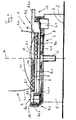
- the Indian FIG. 1 generally designated 1 bottle plate is part of a labeling machine, of which in the FIG. 1 2 is only very schematically arranged around a vertical machine axis rotatably driven rotor or turntable, and forms as well as a variety of further provided on the rotor 2 bottle plate 1, the footing for the bottom 3.1 of upright arranged to be labeled or labeled bottles.
- the bottle plate 1 is formed in two parts in this embodiment, i. it consists of a bottle plate base 4, which is attached to the top of a rotor 2 for each bottle plate 1 separately provided rotating device 5, by means of a screw 6, the center of the bottle plate bottom 4 coaxially with the vertical center axis M of the substantially circular disc-shaped bottle plate. 4 is provided.
- the rotary device is rotatable by a cam control or a servo drive about the axis M in synchronism with the rotational movement of the turntable 2.
- Bottom plate base 4 is formed recessed on its upper side facing away from rotating device 5, namely with a bottom 4.1 abutting against the upper side of rotating device 5 and with a substantially annular edge 4.2 projecting beyond side of bottom 4.1 remote from rotating device 5.
- the edge region 4.2 is step-shaped, i. it consists of an inner ring-like and the central axis M concentrically enclosing section 4.2.1 and an outer, also annular section 4.2.2, which protrudes slightly in the direction of the central axis M over the top of the section 4.2.1.
- the bottle plate 1 further consists of a bottle top, which is twist-proof, but at the same time easily removable held on the bottle bottom plate 4.
- a bottle top part 7a which consists of a substantially disc-shaped plate member 8, which is made of a ferromagnetic material, for example made of stainless steel.
- the plate member 8 is provided with a circular recess 9, so that it has a bottom 8.1, a protruding over the bottom edge 8.2 and a radially outwardly projecting from the edge 8.2 and arranged in a plane parallel to the plane of the bottom 8.1 Has flange 8.3.
- a friction lining 10 is fixed, for example by gluing, which then forms the actual footing for the bottom 3.1 of the respective bottle 3 and is designed, for example, multi-layered, for example with a lower layer of a Tissue and with an overlying layer of a wear-resistant material with a sufficiently high coefficient of friction, for example made of rubber or a synthetic resin material and with a profiled top, which is flush with the top of the flange 8.3 in the illustrated embodiment.
- the flange 8.3 is formed with a plurality of radially projecting tab or wing-like extensions 8.3.1, which are provided in an illustrated embodiment offset by 90 ° about the central axis M and the mounted on the bottle plate lower part 4 bottle top 7a in each case a recess 11 in the section 4.2.2 of the edge area 4.2 are included ( Fig. 2 ), so that thereby the bottle top part 7 a is held against rotation on the bottle plate bottom part 4.
- the provided in the section 4.2.2 recesses 11 are open to the top of the bottle top part 7a and radially outward and inward.
- the bottle plate base 4 is provided on its circumference in each case with a further recess 12.
- the plate member 8 When connected to the bottle plate bottom part 4 bottle top part 7a, the plate member 8 is received with its recessed area in the recess of the bottle plate base 4, in such a way that it rests with the outer surface of the edge 8.2 against the annular surface formed by the section 4.2.1, the flange 8.3 rests with its underside on the upper side of the section 4.2.1, the flange 8.3 is surrounded on the outside by the section 4.2.2 and the recesses 11 in the section 4.2.2 recorded extensions 8.3.1 each slightly above the peripheral surface of the bottle plate bottom part 4th protrude in the region of the lateral recesses 12, so that the extensions 8.3.1 form easily accessible grip surfaces.
- a plurality of permanent magnets 13 are provided in the section 4.2.1 distributed around the central axis M, which in the Fasten lower side of bottle plate 4 inserted bottle top 7a to flange 8.3.
- the bottle top part 7b differs from the bottle top part 7a only in that the recess 9a corresponding to the recess 9 and for receiving the friction lining 10 is made deeper than the recess 9, so that the friction lining 10 lies lower with its upper side as the top of the flange section 8.3.
- a center axis M concentrically enclosing, conical annular centering surface 14 is provided, with a cone angle, which is in the for FIG. 1 selected representation opens upwards.
- the centering surface 14 acts as in the FIG. 1 is shown to the right of the central axis M, with the respective bottle 3 at the transition between the bottom of the bottle 3.1 and bottle circumference wall 3.2 together to center the bottle 3 on the bottle plate 1.
- the advantage of the bottle plate 1 is u.a. in that, when the friction lining 10 is worn and / or when the relevant bottle treatment machine or labeling machine is changed over to bottles 3 with a different diameter or another shape, the existing bottle top parts 7a or 7b can be easily and quickly, i. In particular, even without tools against bottle top parts can be replaced, the friction lining is new and / or the size of the friction lining and / or surrounded by the centering surface 14 footing are adapted to the after conversion to be processed bottles 3.
- FIG. 4 shows in a representation similar FIG. 1 as another possible embodiment, a bottle plate 1 a. While at the in the FIG. 1 On the right hand side embodiment, the bottle top part 7b as a whole, ie exchanged with friction lining 10 and centering surface 14, it is possible with the bottle plate 1 a, with a change of the relevant machine from one type of bottle to another, for example in shape and size different bottle only the centering surface 14th adapt or replace only wear this when wearing the friction lining 10.
- the bottle top part 7b corresponding bottle top 15 is made in two parts and consists of a lower plate member 16, which is formed like an annular ring in the illustrated embodiment and the friction lining 10, and an upper plate member 17 which rests on the top of the plate member 16 and the Centering surface 14 has.
- Both stacked stacked plate members 16 and 17 are in turn on the circumference with the extensions 8.3.1 corresponding and over the other circumference of the elements 16 and 17 projecting wing or tab-like extensions 16.1 and 17.1 provided with the mounted bottle plate 1a in the Recesses 11 corresponding recesses 18 are received at the edge of the bottle bottom plate 4 corresponding and connected to the rotating device 5 bottle bottom plate 19, in such a way that in each recess 18 via an extension 16.1 an extension 17.1 is arranged ( FIG. 5 ).
- the advantage of the bottle plate 1a is that the two plate members 16 and 17 can be replaced independently, namely the lower plate member 16 for renewal of the friction lining 10 and the upper plate member 17 for adjusting the bottle plate 1 a to different bottle shapes and / or diameters.
- the plate element 17 is in this embodiment, in turn, at least in the cooperating with the permanent magnet 13 edge region of a ferromagnetic material, for example made of a suitable metal.
- the friction pad 10 having plate member is made of a suitable metal or plastic.
- the friction lining 10 is attached to this plate element, for example by gluing.
- FIG. 6 shows in a presentation like FIG. 4 a relative to the bottle plate 1 a simplified bottle plate 1 b, in which the center axis M concentrically enclosing annular recess of a bottle plate base 4 corresponding bottle plate base 22 of the friction lining 10 consisting of the lower fabric layer 10.1 and arranged above it, for example made of rubber and at the top profiled layer 10.2 is fixed by gluing.
- the bottle top part 23 corresponding to the bottle top part 7b is interchangeably provided, with the middle recess 24 forming the oblique centering surface 14, within which the friction lining 10 is exposed.
- the bottle top 23 is in turn secured by the engaging in recesses on the edge of the bottle top shell 22 wing-like extensions of the bottle top shell 23 against rotation and by the permanent magnets 13 against lifting.
- the bottle top parts cooperating with the permanent magnets 13 consist of a ferromagnetic material. Like in the FIG. 6 indicated with 25 for the bottle top part 23, it is also possible, the bottle top shells only where they cooperate with the permanent magnet 13 to produce from the ferromagnetic material or to provide with inserts of this material.
Description
- Die Erfindung bezieht sich auf einen Flaschenteller gemäß Oberbegriff Patentanspruch 1, und wie aus der
DE 201 14 062 41 bekannt. - Flaschenteller mit einem Reibbelag als Standfläche für Flaschen oder dergleichen Behälter sowie ggfs. auch mit einer Zentrierfläche zum Zentrieren der Flasche oder des Behälters auf dem Flaschenteller sind bei Flaschen- oder Behälter-Behandlungsmaschinen, insbesondere auch bei Etikettiermaschinen bekannt. Speziell bei Etikettiermaschinen sind die Flaschenteller an jeweils einer Drehvorrichtung befestigt, die ihrerseits an einem um eine vertikale Maschinenachse umlaufenden antreibbaren Drehtisch oder Rotor vorgesehen ist, so dass die mit ihrem Boden auf dem jeweiligen Flaschenteller aufstehenden Flaschen bei umlaufendem Drehtisch über die Drehvorrichtung und den jeweiligen Flaschenteller um ihre vertikale Achse gesteuert gedreht werden, und zwar u.a. für die Übergabe, das Andrücken sowie Anbürsten des jeweiligen Etiketts. Um speziell auch bei hohen Leistungen der Etikettiermaschine ein zuverlässiges Drehen der Flaschen und damit ein einwandfreies Etikettieren zu erreichen, ist es erforderlich, abgenutzte Reibbeläge auszutauschen, die ein exaktes Mitdrehen der jeweiligen Flasche nicht mehr gewährleisten können.
- Sind die Flaschenteller an ihrer Oberseite mit einer die Flaschen im Bereich ihres Bodens zentrierenden Zentrierfläche versehen, die an die Form und/oder den Durchmesser der Flaschen im Bereich des Flaschenbodens angepasst ist, ist es bei Umstellung der Etikettiermaschine von einer Flaschensorte auf eine andere Flaschensorte auch erforderlich, die Flaschenteller mit diesen Zentrierflächen auszuwechseln, was ebenso wie das Auswechseln bzw. Erneuern der Reibbeläge bisher zeit- und kostenaufwändig ist.
- Zweiteilige Flaschenteller bestehend aus einem Flaschentellerunterteil und aus einem auswechselbar und verdrehungssicher an diesem gehaltenen Flaschentelleroberteil sind bekannt. So ist es speziell auch bekannt (
DE 201 14 062 U1 ), an einem Flaschentellerunterteil mit Hilfe von Permanentmagneten ein als Zentrierring ausgeführtes Flaschentelleroberteil lösbar zu befestigen, und zwar derart, dass ein an der Oberseite des Flaschentellerunterteils vorgesehener Reibbelag an einem Randbereich zwischen dem Flaschentellerunterteil und dem Zentrierring gehalten ist. - Bekannt ist weiterhin (
DE 91 11 601 U1 ,DE 86 24 351 U1 ,EP-A-0 330 074 ), einen Flaschenteller mit Reibbelag zweiteilig auszubilden, und zwar wiederum bestehend aus einem Flaschentellerunterteil und einem Flaschentelleroberteil, welches mit angeformten Rasten am Flaschentellerunterteil durch Verrasten wieder lösbar verriegelbar ist, was allerdings u.a. eine relativ aufwändige Formgebung insbesondere für das Flaschentelleroberteil sowie eine umständliche Handhabung beim Auswechseln, insbesondere beim Lösen des Flaschentelleroberteils vom Flaschentellerunterteil bedeutet. - Aufgabe der Erfindung ist es, einen Flaschenteller aufzuzeigen, der diese Nachteile vermeidet und ein schnelles und problemloses Austauschen des jeweiligen Reibbelages und/oder des Zentrierelementes ermöglicht. Zur Lösung dieser Aufgabe ist ein Flaschenteller entsprechend dem Patentanspruch 1 ausgebildet.
- Die Erfindung wird im Folgenden anhand der Figuren an Ausführungsbeispielen näher erläutert:
- Fig. 1
- in vereinfachter Darstellung einen Schnitt durch einen zweiteiligen Flaschenteller bei zwei unterschiedlichen Ausführungsformen der Erfindung;
- Fig. 2 und 3
- in vereinfachter Darstellung eine Draufsicht auf das untere Teil des Flaschentellers (Flaschentellerunterteil) sowie auf das obere, austauschbare Teil des Flaschentellers (Flaschentelleroberteil) der
Figur 1 ; - Fig. 4 und 5
- in vereinfachter Darstellung einen Schnitt durch einen dreiteiligen Flaschenteller sowie eine Teildarstellung und Seitenansicht dieses Flaschentellers;
- Fig. 6
- bei einer weiteren Ausführungsform.
- Der in der
Figur 1 allgemein mit 1 bezeichnete Flaschenteller ist Bestandteil einer Etikettiermaschine, von der in derFigur 1 mit 2 lediglich sehr schematisch ein um eine vertikale Maschinenachse umlaufend antreibbarer Rotor oder Drehtisch angeordnet ist, und bildet ebenso wie eine Vielzahl weiterer am Rotor 2 vorgesehener Flaschenteller 1 die Standfläche für den Boden 3.1 von aufrechtstehend angeordneten, zu etikettierenden oder etikettierten Flaschen 3. - Der Flaschenteller 1 ist bei dieser Ausführungsform zweiteilig ausgebildet, d.h. er besteht aus einem Flaschentellerunterteil 4, welches an der Oberseite einer am Rotor 2 für jeden Flaschenteller 1 gesondert vorgesehenen Drehvorrichtung 5 befestigt ist, und zwar mittels einer Schraube 6, die mittig am Flaschentellerunterteil 4 achsgleich mit der vertikalen Mittelachse M des im wesentlichen kreisscheibenförmigen Flaschentellers 4 vorgesehen ist. Die Drehvorrichtung ist durch eine Kurvensteuerung oder einen Servoantrieb um die Achse M synchron mit der Drehbewegung des Drehtisches 2 drehbar.
- Die exakte Zentrierung des Flaschentellers 1 an der Drehvorrichtung 5 erfolgt über einen Zapfen 6.1, der an der Oberseite der Drehvorrichtung 5 vorgesehen ist und in eine entsprechende Bohrung des Flaschentellerunterteils 4 eingreift.
- Das Flaschentellerunterteil 4 ist an seiner der Drehvorrichtung 5 abgewandten Oberseite vertieft ausgebildet, und zwar mit einem gegen die Oberseite der Drehvorrichtung 5 anliegenden Boden 4.1 und mit einem über die der Drehvorrichtung 5 abgewandte Seite des Bodens 4.1 überstehenden, im wesentlichen ringförmigen Rand 4.2. Der Randbereich 4.2 ist stufenförmig ausgebildet, d.h. er besteht aus einem inneren ringartigen und die Mittelachse M konzentrisch umschließenden Abschnitt 4.2.1 und einem äußeren, ebenfalls ringförmigen Abschnitt 4.2.2, der in Richtung der Mittelachse M etwas über die Oberseite des Abschnittes 4.2.1 vorsteht.
- Der Flaschenteller 1 besteht weiterhin aus einem Flaschentelleroberteil, welches verdrehungssicher, zugleich aber problemlos abnehmbar auf dem Flaschentellerunterteil 4 gehalten ist.
- In der
Figur 1 ist links ein Flaschentelleroberteil 7a dargestellt, welches aus einem im wesentlichen scheibenförmigen Tellerelement 8 besteht, das aus einem ferromagnetischen Material, beispielsweise aus nicht rostendem Stahl hergestellt ist. In der Mitte ist das Tellerelement 8 mit einer kreisförmigen Vertiefung 9 versehen, so dass es einen Boden 8.1, einen über den Boden wegstehenden Rand 8.2 sowie einen von dem Rand 8.2 radial nach außen wegstehenden und in einer Ebene parallel zur Ebene des Bodens 8.1 angeordneten ringförmigen Flansch 8.3 aufweist. In der Ausnehmung 9 ist ein Reibbelag 10 z.B. durch Einkleben befestigt, der dann die eigentliche Standfläche für den Boden 3.1 der jeweiligen Flasche 3 bildet und beispielsweise mehrlagig ausgeführt ist, z.B. mit einer unteren Lage aus einem Gewebe und mit einer darüber angeordneten Lage aus einem verschleißfesten Material mit ausreichend hohem Reibungskoeffizienten, beispielsweise aus Gummi oder einem Kunstharzmaterial und mit einer profilierten Oberseite, die bei der dargestellten Ausführungsform bündig mit der Oberseite des Flansches 8.3 liegt. - Der Flansch 8.3 ist mit mehreren radial überstehenden laschen- oder flügelartigen Verlängerungen 8.3.1 ausgebildet, die bei einer dargestellten Ausführungsform um 90° um die Mittelachse M versetzt vorgesehen sind und die bei auf das Flaschentellerunterteil 4 aufgesetztem Flaschentelleroberteil 7a in jeweils einer Ausnehmung 11 im Abschnitt 4.2.2 des Randbereichs 4.2 aufgenommen sind (
Fig. 2 ), so dass hierdurch das Flaschentelleroberteil 7a verdrehungssicher auf dem Flaschentellerunterteil 4 gehalten ist. Die in dem Abschnitt 4.2.2 vorgesehenen Ausnehmungen 11 sind zur Oberseite des Flaschentelleroberteils 7a sowie radial nach außen und innen hin offen. Im Bereich jeder Ausnehmung 11 ist das Flaschentellerunterteil 4 an seinem Umfang jeweils mit einer weiteren Aussparung 12 versehen. - Bei mit dem Flaschentellerunterteil 4 verbundenem Flaschentelleroberteil 7a ist das Tellerelement 8 mit seinem vertieften Bereich in der Vertiefung des Flaschentellerunterteils 4 aufgenommen, und zwar derart, dass es mit der Außenfläche des Randes 8.2 gegen die von dem Abschnitt 4.2.1 gebildete Ringfläche anliegt, der Flansch 8.3 mit seiner Unterseite auf der Oberseite des Abschnittes 4.2.1 aufliegt, der Flansch 8.3 außen von dem Abschnitt 4.2.2 umschlossen ist und die von den Ausnehmungen 11 im Abschnitt 4.2.2 aufgenommenen Verlängerungen 8.3.1 jeweils etwas über die Umfangsfläche des Flaschentellerunterteils 4 im Bereich der seitlichen Ausnehmungen 12 vorstehen, so dass die Verlängerungen 8.3.1 leicht zugängliche Griff-Flächen bilden.
- Um das Flaschentelleroberteil 7a auch in Richtung der Mittelachse M gegen Abheben von dem Flaschentellerunterteil 4 zu sichern, gleichzeitig aber ein schnelles Auswechseln des Flaschentelleroberteils 7a zu ermöglichen, sind im Abschnitt 4.2.1 um die Mittelachse M verteilt mehrere Permanentmagnete 13 vorgesehen, die das in das Flaschentellerunterteil 4 eingesetzte Flaschentelleroberteil 7a am Flansch 8.3 fixieren.
- Das in der
Figur 1 rechts von der Mittelachse M dargestellte Flaschentelleroberteil 7b unterscheidet sich von dem Flaschentelleroberteil 7a lediglich dadurch, dass die der Ausnehmung 9 entsprechende und zur Aufnahme des Reibbelages 10 dienende Ausnehmung 9a tiefer ausgeführt ist als die Ausnehmung 9, so dass der Reibbelag 10 mit seiner Oberseite tiefer liegt als die Oberseite des Flanschabschnittes 8.3. Am Übergang zwischen der Oberseite des Flansches 8.3 und der Oberseite des Reibbelages 10 ist eine die Mittelachse M konzentrisch umschließende, kegelringförmige Zentrierfläche 14 vorgesehen, und zwar mit einem Kegelwinkel, der sich bei der für dieFigur 1 gewählten Darstellung nach oben hin öffnet. Die Zentrierfläche 14 wirkt, wie in derFigur 1 rechts von der Mittelachse M dargestellt ist, mit der jeweiligen Flasche 3 am Übergang zwischen Flaschenboden 3.1 und Flaschenumfangswand 3.2 zusammen, um die Flasche 3 auch auf dem Flaschenteller 1 zu zentrieren. - Der Vorteil des Flaschentellers 1 besteht u.a. darin, dass bei einer Abnutzung des Reibbelages 10 und/oder bei einer Umstellung der betreffenden Flaschenbehandlungsmaschine bzw. Etikettiermaschine auf Flaschen 3 mit einem anderen Durchmesser oder einer anderen Form die vorhandenen Flaschentelleroberteile 7a bzw. 7b problemlos und schnell, d.h. insbesondere auch ohne Werkzeug gegen Flaschentelleroberteile ausgetauscht werden können, deren Reibbelag neu ist und/oder die hinsichtlich Größe des Reibbelages und/oder der von der Zentrierfläche 14 umschlossenen Standfläche an die nach der Umstellung zu verarbeitenden Flaschen 3 angepasst sind.
- Die
Figur 4 zeigt in einer Darstellung ähnlichFigur 1 als weitere mögliche Ausführungsform einen Flaschenteller 1 a. Während bei der in derFigur 1 rechts dargestellten Ausführungsform das Flaschentelleroberteil 7b insgesamt, d.h. mit Reibbelag 10 und Zentrierfläche 14 ausgetauscht wird, ist es bei dem Flaschenteller 1 a möglich, bei einer Umstellung der betreffenden Maschine von einer Flaschenart auf eine andere beispielsweise in Form und Größe unterschiedliche Flaschenart nur die Zentrierfläche 14 anzupassen oder aber bei Abnutzung des Reibbelages 10 nur diesen auszutauschen. - Hierfür ist das dem Flaschentelleroberteil 7b entsprechende Flaschentelleroberteil 15 zweiteilig ausgeführt und besteht aus einem unteren Tellerelement 16, welches bei der dargestellten Ausführungsform kreisringartig ausgebildet ist und den Reibbelag 10 aufweist, und aus einem oberen Tellerelement 17, welches auf der Oberseite des Tellerelementes 16 aufliegt und die Zentrierfläche 14 besitzt. Beide stapelartig übereinander angeordneten Tellerelemente 16 und 17 sind wiederum am Umfang mit den den Verlängerungen 8.3.1 entsprechenden und über den sonstigen Umfang der Elemente 16 und 17 vorstehenden flügel- oder laschenartigen Verlängerungen 16.1 bzw. 17.1 versehen, die bei montiertem Flaschenteller 1a in den den Ausnehmungen 11 entsprechenden Ausnehmungen 18 am Rand des dem Flaschentellerunterteil 4 entsprechenden und mit der Drehvorrichtung 5 verbundenen Flaschentellerunterteils 19 aufgenommen sind, und zwar derart, dass in jeder Ausnehmung 18 über einer Verlängerungen 16.1 eine Verlängerung 17.1 angeordnet ist (
Figur 5 ). - Die Sicherung des zweiteiligen Flaschentelleroberteils 15 am Flaschentellerunterteil 19 gegen Abheben erfolgt wiederum durch die Permanentmagnete 13, die im Flaschentellerunterteil 19 so angeordnet sind, dass jeder Permanentmagnet 13 jeweils durch eine Öffnung 20 am Rand des Tellerelementes 16 hineinreicht und mit dem Randbereich des darüber liegenden Tellerelementes 17 zusammenwirkt, so dass über die Permanentmagnete 13 die beiden Tellerelemente 16 und 17 durch die Magnetkraft gegen unerwünschtes Abheben gesichert sind und das untere Tellerelemente 16 zusätzlich auch noch gegen Verdrehen durch die die Öffnungen 20 durchgreifenden Permanentmagnete 13. Grundsätzlich besteht hierdurch bei dieser Ausführung auch die Möglichkeit, auf die Verlängerungen 16.1 an dem Tellerelement 16 zu verzichten.
- Der Vorteil des Flaschentellers 1a besteht darin, dass die beiden Tellerelemente 16 und 17 unabhängig voneinander ausgetauscht werden können, und zwar das untere Tellerelement 16 zur Erneuerung des Reibbelages 10 und das obere Tellerelement 17 zur Anpassung des Flaschentellers 1 a an unterschiedliche Flaschenformen und/oder -durchmesser. Das Tellerelement 17 ist bei dieser Ausführungsform wiederum zumindest in dem mit dem Permanentmagneten 13 zusammenwirkenden Randbereich aus einem ferromagnetischen Material, beispielsweise aus einem geeigneten Metall gefertigt. Das den Reibbelag 10 aufweisende Tellerelement ist aus einem geeigneten Metall oder Kunststoff gefertigt. Der Reibbelag 10 ist an diesem Tellerelement beispielsweise durch Verkleben befestigt.
- Die
Figur 6 zeigt in einer Darstellung wieFigur 4 einen gegenüber dem Flaschenteller 1 a vereinfachten Flaschenteller 1b, bei dem in einer die Mittelachse M konzentrisch umschließenden ringförmigen Vertiefung eines dem Flaschentellerunterteil 4 entsprechenden Flaschentellerunterteils 22 der Reibbelag 10 bestehend aus der unteren Gewebeschicht 10.1 und der darüber angeordneten, beispielsweise aus Gummi gefertigten und an der Oberseite profilierten Schicht 10.2 durch Verkleben befestigt ist. Auf der Oberseite des mit seiner Unterseite auf der Drehvorrichtung 5 befestigten Drehtellerunterteils 22 ist dann austauschbar das dem Flaschentelleroberteil 7b entsprechende Flaschentelleroberteil 23 vorgesehen, und zwar mit der die schräge Zentrierfläche 14 bildenden mittleren Ausnehmung 24, innerhalb der der Reibbelag 10 frei liegt. - Das Flaschentelleroberteil 23 ist wiederum durch die in Ausnehmungen am Rand des Flaschentelleroberteils 22 eingreifenden flügelartigen Verlängerungen des Flaschentelleroberteils 23 gegen Verdrehen und durch die Permanentmagnete 13 gegen Abheben gesichert.
- Die Erfindung wurde voranstehend an Ausführungsbeispielen beschrieben.
- Vorstehend wurde davon ausgegangen, dass die mit den Permanentmagneten 13 zusammenwirkenden Flaschentelleroberteile aus einem ferromagnetischen Material bestehen. Wie in der
Figur 6 mit 25 für das Flaschentelleroberteil 23 angedeutet, besteht auch die Möglichkeit, die Flaschentelleroberteile nur dort, wo sie mit den Permanentmagneten 13 zusammenwirken aus dem ferromagnetischen Material herzustellen bzw. mit Einsätzen aus diesem Material zu versehen. -
- 1, 1a, 1b
- Flaschenteller
- 2
- Rotor bzw. Drehtisch einer Flaschenbehandlungsmaschine
- 3
- Flasche
- 3.1
- Flaschenboden
- 3.2
- Flaschenumfangswand
- 4
- Flaschentellerunterteil
- 4.1
- Boden
- 4.2
- Rand
- 4.2.1, 4.2.2
- Abschnitt des Randes 4.2
- 5
- Drehvorrichtung
- 6
- Befestigungsschraube
- 6.1
- Zapfen
- 7, 7a
- Flaschentelleroberteil
- 8
- Tellerelement
- 8.1
- Boden
- 8.2
- Rand
- 8.3
- Flansch
- 8.3.1
- Flügelartige Verlängerung zur Drehsicherung
- 9, 9a
- Ausnehmung
- 10
- Reibbelag
- 10.1
- Gewebeschicht
- 10.2
- verschleißfeste Reibbelagoberschicht aus Kunststoff
- 11
- Ausnehmung für die flügelartigen Verlängerungen 8.3.1
- 12
- Aussparung am Umfang des Flaschentellerunterteils 4
- 13
- Permanentmagnet
- 14
- kegelringförmige Zentrierfläche
- 15
- Flaschentelleroberteil
- 16, 17
- Tellerelemente
- 16.1, 17.1
- flügelartige Verlängerung zur Drehsicherung
- 18
- Ausnehmung am Rand des Flaschentellerunterteils
- 19
- Flaschentellerunterteil
- 20
- Bohrung
- 21
- Ausnehmung im Flaschentellerunterteil 22
- 22
- Flaschentellerunterteil
- 23
- Flaschentelleroberteil
- 24
- Öffnung im Flaschentelleroberteil 23 mit Zentrierfläche 14
M vertikale Mittelachse
Claims (12)
- Flaschenteller zur Verwendung bei Behälter- oder Flaschenbehandlungsmaschinen, beispielsweise bei Etikettenmaschinen, als um eine Flaschentellermittelachse (M) gesteuert drehbare und von einem Reibbelag (10) gebildete Behälterstandfläche, wobei der Flaschenteller (1, 1 a, 1 b) wenigstens zweiteilig mit einem an einer Drehvorrichtung (5) der Behandlungsmaschine befestigbaren Flaschentellerunterteil (4, 19, 22) und mit wenigstens einem an der Oberseite des Flaschentellerunterteils auswechselbar befestigten Flaschentelleroberteil (7a, 7b, 15, 23) ausgebildet ist, welches durch formschlüssiges Ineinandergreifen von Flaschentellerunterteil und Flaschentelleroberteil verdrehungssicher und durch lösbare Verriegelungsmittel (13) gegen Abheben gesichert an dem Flaschentellerunterteil (4, 19, 22) gehalten ist, dadurch gekennzeichnet, dass das Flaschentelleroberteil (7a, 7b, 15, 23) mit wenigstens einem über seinen Umfang flügelartig wegstehenden Abschnitt (8.3.1, 16.1, 17.1) versehen ist, und dass der flügelartige Abschnitt (8.3.1, 16.1, 17.1) zur drehfesten Verbindung zwischen dem Flaschentelleroberteil (7a, 7b, 15, 23) und dem Flaschentellerunterteil (4, 19, 22) in eine am Rand des Flaschentellerunterteils (4, 19, 22) an dessen Oberseite vorgesehene offene Ausnehmung (11, 18) eingreift.
- Flaschenteller nach Anspruch 1, dadurch gekennzeichnet, dass das Flaschentellerunterteil (4, 19, 22) an seiner Oberseite mit einem überstehenden Rand (4.1) versehenen und dass in dem überstehenden Rand (4.1) wenigstens eine an der Oberseite des Flaschentellerunterteils (4, 19, 22) offene Ausnehmung (11, 18) für wenigstens einen flügelartigen Abschnitt (8.3.1, 16.1, 17.1) vorgesehen ist.
- Flaschenteller nach Anspruch 1 oder 2, dadurch gekennzeichnet, dass die lösbaren Verriegelungsmittel von wenigstens einem Permanentmagneten (13) gebildet sind.
- Flaschenteller nach Anspruch 3, dadurch gekennzeichnet, dass wenigstens zwei Permanentmagnete (13) um die Flaschentellermittelachse (M) verteilt und von dieser radial beabstandet vorgesehen sind.
- Flaschenteller nach einem der vorhergehenden Ansprüche, dadurch gekennzeichnet, dass das auswechselbare Flaschentelleroberteil (7a, 7b, 15) den Reibbelag (10) aufweist.
- Flaschenteller nach einem der vorhergehenden Ansprüche, dadurch gekennzeichnet, dass das auswechselbare Flaschentelleroberteil (7b, 15, 23) als Zentrierelement mit einer dem Reibbelag (10) zumindest in Teilbereichen umschließenden Zentrierfläche (14) für die Flaschen (3) oder dergleichen Behälter ausgebildet ist.
- Flaschenteller nach einem der vorhergehenden Ansprüche 1-4, dadurch gekennzeichnet, dass der Reibbelag (10) am Flaschentellerunterteil (22) vorgesehen ist.
- Flaschenteller nach einem der vorhergehenden Ansprüche 1-6, dadurch gekennzeichnet, dass das Flaschentelleroberteil (15) wenigstens zweiteilig mit zwei übereinander angeordneten Tellerelementen (16, 17) ausgebildet ist.
- Flaschenteller nach Anspruch 8, dadurch gekennzeichnet, dass ein oberes, dem Flaschentellerunterteil (19) entfernt liegendes Tellerelement (16) als Zentrierteller mit einer Zentrierfläche (14) und ein dem Flaschentellerunterteil (19) näherliegendes oder benachbart liegendes Tellerteil den Reibbelag (10) aufweist oder diesen Belag bildet.
- Flaschenteller nach Anspruch 1, dadurch gekennzeichnet, dass bei zweiteiliger Ausbildung des Flaschentelleroberteils (15) zumindest ein die Oberseite des Flaschentellers (1a) bildende Tellerelement (16) den flügelartigen Abschnitt (16.1) aufweist.
- Flaschenteller nach Anspruch 10, dadurch gekennzeichnet, dass sämtliche Tellerelemente (16, 17) des Flaschentelleroberteils (15) den wenigstens einen überstehenden flügelartigen Abschnitt (16.1, 17.1) aufweisen, und dass die flügelartigen Abschnitte (16.1, 17.1) jeweils in die, beispielsweise gemeinsame Ausnehmung (18) des Flaschentellerunterteils (19) aufgenommen sind.
- Flaschenteller nach einem der vorhergehenden Ansprüche, dadurch gekennzeichnet, dass der wenigstens eine flügelartige Abschnitt (8.3.1, 16.1, 17.1) eine Griff-Fläche zum Abnehmen des Flaschentelleroberteils (7a, 7b, 15, 23) bildet.
Priority Applications (1)
| Application Number | Priority Date | Filing Date | Title |
|---|---|---|---|
| PL05022091T PL1657162T3 (pl) | 2004-11-12 | 2005-10-11 | Talerz butelkowy |
Applications Claiming Priority (1)
| Application Number | Priority Date | Filing Date | Title |
|---|---|---|---|
| DE102004054891A DE102004054891A1 (de) | 2004-11-12 | 2004-11-12 | Flaschenteller |
Publications (2)
| Publication Number | Publication Date |
|---|---|
| EP1657162A1 EP1657162A1 (de) | 2006-05-17 |
| EP1657162B1 true EP1657162B1 (de) | 2008-10-29 |
Family
ID=35788177
Family Applications (1)
| Application Number | Title | Priority Date | Filing Date |
|---|---|---|---|
| EP05022091A Active EP1657162B1 (de) | 2004-11-12 | 2005-10-11 | Flaschenteller |
Country Status (5)
| Country | Link |
|---|---|
| US (2) | US7673435B2 (de) |
| EP (1) | EP1657162B1 (de) |
| AT (1) | ATE412580T1 (de) |
| DE (2) | DE102004054891A1 (de) |
| PL (1) | PL1657162T3 (de) |
Cited By (1)
| Publication number | Priority date | Publication date | Assignee | Title |
|---|---|---|---|---|
| DE202020107090U1 (de) | 2020-12-09 | 2022-03-10 | Krones Ag | Auflageteller zur bodenseitigen Aufnahme und Drehpositionierung von Flaschen |
Families Citing this family (18)
| Publication number | Priority date | Publication date | Assignee | Title |
|---|---|---|---|---|
| DE102004054891A1 (de) * | 2004-11-12 | 2006-05-24 | Khs Ag | Flaschenteller |
| DE202006018378U1 (de) | 2006-12-05 | 2008-01-10 | Krones Ag | Auflageteller |
| US8147616B2 (en) * | 2007-10-22 | 2012-04-03 | Stokely-Van Camp, Inc. | Container rinsing system and method |
| US9168569B2 (en) | 2007-10-22 | 2015-10-27 | Stokely-Van Camp, Inc. | Container rinsing system and method |
| RS52250B (en) * | 2008-05-02 | 2012-10-31 | Indag Gesellschaft für Industriebedarf mbH & Co. Betriebs KG | FLEXIBLE BAG HANDLING DEVICE |
| DE102009016321B4 (de) * | 2009-04-06 | 2015-06-25 | Khs Gmbh | Zentrierelement für Behälterträger an Behälterbehandlungsmaschinen, Behälterträger sowie Behälterbehandlungsmaschinen mit derartigen Behälterträgern |
| US9452866B2 (en) * | 2011-09-22 | 2016-09-27 | Nestec S.A. | Cup support and dispensing device |
| DE102012108928A1 (de) * | 2012-09-21 | 2014-03-27 | Krones Ag | Verfahren und Vorrichtung zum Transportieren von mit Flüssigkeit gefüllten Behältern |
| RU2016105456A (ru) * | 2013-07-19 | 2017-08-24 | Вилко Аг | Способ поточного испытания устройств и установка для испытания |
| DE202014102157U1 (de) | 2014-05-08 | 2015-08-11 | Krones Aktiengesellschaft | Auflageteller und Vorrichtung mit einer Mehrzahl solcher Auflageteller zur Aufnahme von Behältern |
| DE202014105768U1 (de) | 2014-11-28 | 2016-03-01 | Krones Aktiengesellschaft | Auflageteller zur Verwendung bei Behälterbehandlungs- und/oder Ausstattungsvorrichtungen und Behälterbehandlungs- und/oder Ausstattungsvorrichtung mit mehreren Auflagetellern |
| DE102017120083A1 (de) * | 2017-08-31 | 2019-02-28 | Krones Ag | Vorrichtung mit Schnellwechsel Tellerträger und verschiebbarer Führungskurve |
| DE102017215443A1 (de) * | 2017-09-04 | 2019-03-07 | Krones Ag | Rundläufermaschine zur Behandlung von Behältern |
| CN108082637A (zh) * | 2017-12-29 | 2018-05-29 | 广州科已达智能科技有限公司 | 一种卧式贴标机 |
| GB2573856B (en) * | 2018-03-12 | 2020-06-03 | Ebar Initiatives Ltd | Dispenser system and method of use |
| DE202018103835U1 (de) * | 2018-07-04 | 2018-07-13 | Krones Ag | System aus einem Standteller und einer Auflage und Direktdruckmaschine |
| CN109047231B (zh) * | 2018-07-23 | 2020-09-25 | 重庆岩泉食品有限公司 | 一种大口径水果玻璃罐头瓶身冲洗设备 |
| CN113414615B (zh) * | 2021-06-28 | 2022-08-19 | 南昌大学科学技术学院 | 一种可移动式数控机械 |
Family Cites Families (25)
| Publication number | Priority date | Publication date | Assignee | Title |
|---|---|---|---|---|
| US3527334A (en) * | 1968-08-30 | 1970-09-08 | Owens Illinois Inc | Registration device |
| US3982377A (en) * | 1971-05-10 | 1976-09-28 | Bmt Manufacturing Corporation | Automatic bagging machine |
| GB1484262A (en) * | 1973-09-27 | 1977-09-01 | Metal Box Co Ltd | Capping machine |
| US4143754A (en) * | 1977-07-07 | 1979-03-13 | Morgan Fairest Limited | Labelling machines with article guide plate |
| US4497409A (en) * | 1982-12-27 | 1985-02-05 | Chong Wun C | Seam inspection apparatus |
| DE3514239C1 (de) * | 1985-04-19 | 1986-06-05 | Jagenberg AG, 4000 Düsseldorf | Flaschenteller in einer Flaschenbehandlungsmaschine |
| US4624098A (en) * | 1985-10-23 | 1986-11-25 | Owens-Illinois, Inc. | Container restraint system |
| DE8624351U1 (de) * | 1986-09-11 | 1986-11-06 | Krones Ag Hermann Kronseder Maschinenfabrik, 8402 Neutraubling | Drehteller für Gefäßbehandlungsmaschinen |
| DE3806919A1 (de) * | 1987-05-23 | 1988-12-15 | Eti Tec Maschinenbau | Stuetzplatte fuer flaschendrehteller in etikettiermaschinen |
| US4950350A (en) * | 1987-05-23 | 1990-08-21 | Holstein Und Kappert Ag | Machine for labelling bottles |
| DE3805854A1 (de) * | 1988-02-25 | 1989-09-07 | Eti Tec Maschinenbau | Stuetzplatte fuer einen drehteller in einer behandlungsmaschine fuer gegenstaende, insbesondere einer etikettiermaschine fuer behaelter |
| DE3735882C1 (de) * | 1987-10-23 | 1988-12-01 | Eti Tec Maschb Gmbh | Antrieb fuer einen Drehteller in einer Etikettiermaschine fuer Flaschen |
| DE4005606C1 (de) * | 1990-02-22 | 1991-09-19 | Krones Ag Hermann Kronseder Maschinenfabrik, 8402 Neutraubling, De | |
| DE9006376U1 (de) * | 1990-06-06 | 1991-05-02 | Krones Ag Hermann Kronseder Maschinenfabrik, 8402 Neutraubling, De | |
| DE9111601U1 (de) * | 1991-09-18 | 1993-01-21 | Khs Eti-Tec Maschinenbau Gmbh, 4006 Erkrath, De | |
| IT1265518B1 (it) * | 1993-01-26 | 1996-11-22 | Alfa Costr Mecc Spa | Piattello porta-bottiglie con dispositivo centratore in macchine etichettatrici. |
| US5473855A (en) * | 1994-08-09 | 1995-12-12 | Hidding; Walter E. | System for installing closures on containers |
| DE19513064B4 (de) * | 1995-04-07 | 2004-04-01 | Khs Maschinen- Und Anlagenbau Ag | Verfahren sowie System zum Füllen von Behältern mit einem flüssigen Füllgut sowie Füllmaschine und Etikettiereinrichtung zur Verwendung bei diesem Verfahren oder System |
| DE19814625A1 (de) * | 1998-04-01 | 1999-10-07 | Khs Masch & Anlagenbau Ag | Vortisch für Gefäßbehandlungsmaschinen |
| DE19919767C2 (de) * | 1999-03-22 | 2003-10-16 | Rudolf Zodrow | Drehteller für Flaschen in einer Flaschenbehandlungsmaschine |
| US6546697B2 (en) * | 2001-07-31 | 2003-04-15 | Hormel Foods, Llc | Method and apparatus for packaging tamales |
| DE20114062U1 (de) * | 2001-08-25 | 2002-02-07 | Khs Masch & Anlagenbau Ag | Stützplatte eines Drehtellers in einer Behandlungsmaschine für Gegenstände, insbesondere einer Etikettiermaschine für Flaschen |
| DE102004054891A1 (de) * | 2004-11-12 | 2006-05-24 | Khs Ag | Flaschenteller |
| US7708136B2 (en) * | 2006-04-20 | 2010-05-04 | Turbofil Packaging Machines, Llc | Carrier puck |
| US20080054525A1 (en) * | 2006-09-06 | 2008-03-06 | Graham Packaging Company, Lp | Method and apparatus for stretching the neck finish of a molded plastic article |
-
2004
- 2004-11-12 DE DE102004054891A patent/DE102004054891A1/de not_active Ceased
-
2005
- 2005-10-11 EP EP05022091A patent/EP1657162B1/de active Active
- 2005-10-11 PL PL05022091T patent/PL1657162T3/pl unknown
- 2005-10-11 DE DE502005005794T patent/DE502005005794D1/de active Active
- 2005-10-11 AT AT05022091T patent/ATE412580T1/de not_active IP Right Cessation
- 2005-11-12 US US11/271,166 patent/US7673435B2/en active Active
-
2010
- 2010-02-16 US US12/706,185 patent/US7980380B2/en active Active
Cited By (1)
| Publication number | Priority date | Publication date | Assignee | Title |
|---|---|---|---|---|
| DE202020107090U1 (de) | 2020-12-09 | 2022-03-10 | Krones Ag | Auflageteller zur bodenseitigen Aufnahme und Drehpositionierung von Flaschen |
Also Published As
| Publication number | Publication date |
|---|---|
| DE102004054891A1 (de) | 2006-05-24 |
| ATE412580T1 (de) | 2008-11-15 |
| US7673435B2 (en) | 2010-03-09 |
| PL1657162T3 (pl) | 2009-04-30 |
| EP1657162A1 (de) | 2006-05-17 |
| US7980380B2 (en) | 2011-07-19 |
| US20060117708A1 (en) | 2006-06-08 |
| DE502005005794D1 (de) | 2008-12-11 |
| US20100140049A1 (en) | 2010-06-10 |
Similar Documents
| Publication | Publication Date | Title |
|---|---|---|
| EP1657162B1 (de) | Flaschenteller | |
| EP2001749B1 (de) | Vakuumtrommel für die rundum-etikettierung von flaschen oder dergleichen behälter | |
| EP2567903B1 (de) | Etikettiervorrichtung | |
| EP1493368B1 (de) | Kaffeemühle für eine Kaffeemaschine | |
| EP2558191B1 (de) | MISCHVORRICHTUNG MIT VERSCHLEIßSCHUTZAUSKLEIDUNG | |
| DE19539694A1 (de) | Schnellwechsel-Sternrad für eine Verschließmaschine | |
| DE102006033511A1 (de) | Behandlungsmaschine | |
| EP2099683B1 (de) | Auflageteller | |
| DE102006035802B4 (de) | Transportwalze, insbesondere Schneidwalze für ein Etikettieraggregat sowie Etikettieraggregat mit einer solchen Walze | |
| EP1669321B1 (de) | Verschliessmaschine für Flaschen oder dergleichen Behälter | |
| EP1659088B1 (de) | Verschliessmaschine für Flaschen oder dergleichen Behälter | |
| WO2008014883A1 (de) | VERSCHLIEßMASCHINE | |
| DE102009016321B4 (de) | Zentrierelement für Behälterträger an Behälterbehandlungsmaschinen, Behälterträger sowie Behälterbehandlungsmaschinen mit derartigen Behälterträgern | |
| DE1657167B2 (de) | Verschliessmaschine zum wahlweisen aufbringen von kronenkorken und leichtmetallverschlusskappen auf flaschenmuendungen | |
| EP1782918B1 (de) | Aufnahme für ein Schleifwerkzeug, Schleifwerkzeug und Tragkörper für ein Schleifwerkzeug | |
| EP2301885B9 (de) | Vorrichtung zum Verschließen von Gefäßen mit einem Verschluss | |
| EP0443617B1 (de) | Vorrichtung zum Zentrieren und Ausrichten von Gefässen | |
| DE202006011787U1 (de) | Transportwalze, insbesondere Schneidwalze für ein Etikettieraggregat sowie Etikettieraggregat mit einer solchen Walze | |
| EP2326558A1 (de) | Lageranordnung sowie etikettiermaschine mit einer solchen lageranordnung | |
| DE202020107090U1 (de) | Auflageteller zur bodenseitigen Aufnahme und Drehpositionierung von Flaschen | |
| DE7148902U (de) | Verschliesskopf zum aufschrauben von kunststoffschraubverschluessen auf flaschen | |
| DE19513411A1 (de) | Vorrichtung zur Anordnung eines Transportsternes in einer Behälterbehandlungsanlage | |
| EP0895937A1 (de) | Vorrichtung zum Anbringen von Etiketten auf konische Flächen von Gegenständen | |
| EP0806365A1 (de) | Etikettiermaschine für offene Behälter, insbesondere Becher |
Legal Events
| Date | Code | Title | Description |
|---|---|---|---|
| PUAI | Public reference made under article 153(3) epc to a published international application that has entered the european phase |
Free format text: ORIGINAL CODE: 0009012 |
|
| AK | Designated contracting states |
Kind code of ref document: A1 Designated state(s): AT BE BG CH CY CZ DE DK EE ES FI FR GB GR HU IE IS IT LI LT LU LV MC NL PL PT RO SE SI SK TR |
|
| AX | Request for extension of the european patent |
Extension state: AL BA HR MK YU |
|
| 17P | Request for examination filed |
Effective date: 20061117 |
|
| AKX | Designation fees paid |
Designated state(s): AT BE BG CH CY CZ DE DK EE ES FI FR GB GR HU IE IS IT LI LT LU LV MC NL PL PT RO SE SI SK TR |
|
| 17Q | First examination report despatched |
Effective date: 20070125 |
|
| GRAP | Despatch of communication of intention to grant a patent |
Free format text: ORIGINAL CODE: EPIDOSNIGR1 |
|
| GRAS | Grant fee paid |
Free format text: ORIGINAL CODE: EPIDOSNIGR3 |
|
| GRAA | (expected) grant |
Free format text: ORIGINAL CODE: 0009210 |
|
| AK | Designated contracting states |
Kind code of ref document: B1 Designated state(s): AT BE BG CH CY CZ DE DK EE ES FI FR GB GR HU IE IS IT LI LT LU LV MC NL PL PT RO SE SI SK TR |
|
| REG | Reference to a national code |
Ref country code: GB Ref legal event code: FG4D Free format text: NOT ENGLISH |
|
| REG | Reference to a national code |
Ref country code: CH Ref legal event code: EP |
|
| REG | Reference to a national code |
Ref country code: IE Ref legal event code: FG4D Free format text: LANGUAGE OF EP DOCUMENT: GERMAN |
|
| REF | Corresponds to: |
Ref document number: 502005005794 Country of ref document: DE Date of ref document: 20081211 Kind code of ref document: P |
|
| NLV1 | Nl: lapsed or annulled due to failure to fulfill the requirements of art. 29p and 29m of the patents act | ||
| LTIE | Lt: invalidation of european patent or patent extension |
Effective date: 20081029 |
|
| PG25 | Lapsed in a contracting state [announced via postgrant information from national office to epo] |
Ref country code: LT Free format text: LAPSE BECAUSE OF FAILURE TO SUBMIT A TRANSLATION OF THE DESCRIPTION OR TO PAY THE FEE WITHIN THE PRESCRIBED TIME-LIMIT Effective date: 20081029 Ref country code: ES Free format text: LAPSE BECAUSE OF FAILURE TO SUBMIT A TRANSLATION OF THE DESCRIPTION OR TO PAY THE FEE WITHIN THE PRESCRIBED TIME-LIMIT Effective date: 20090209 |
|
| REG | Reference to a national code |
Ref country code: PL Ref legal event code: T3 |
|
| PG25 | Lapsed in a contracting state [announced via postgrant information from national office to epo] |
Ref country code: IS Free format text: LAPSE BECAUSE OF FAILURE TO SUBMIT A TRANSLATION OF THE DESCRIPTION OR TO PAY THE FEE WITHIN THE PRESCRIBED TIME-LIMIT Effective date: 20090228 Ref country code: FI Free format text: LAPSE BECAUSE OF FAILURE TO SUBMIT A TRANSLATION OF THE DESCRIPTION OR TO PAY THE FEE WITHIN THE PRESCRIBED TIME-LIMIT Effective date: 20081029 Ref country code: PT Free format text: LAPSE BECAUSE OF FAILURE TO SUBMIT A TRANSLATION OF THE DESCRIPTION OR TO PAY THE FEE WITHIN THE PRESCRIBED TIME-LIMIT Effective date: 20090330 Ref country code: SI Free format text: LAPSE BECAUSE OF FAILURE TO SUBMIT A TRANSLATION OF THE DESCRIPTION OR TO PAY THE FEE WITHIN THE PRESCRIBED TIME-LIMIT Effective date: 20081029 Ref country code: NL Free format text: LAPSE BECAUSE OF FAILURE TO SUBMIT A TRANSLATION OF THE DESCRIPTION OR TO PAY THE FEE WITHIN THE PRESCRIBED TIME-LIMIT Effective date: 20081029 Ref country code: LV Free format text: LAPSE BECAUSE OF FAILURE TO SUBMIT A TRANSLATION OF THE DESCRIPTION OR TO PAY THE FEE WITHIN THE PRESCRIBED TIME-LIMIT Effective date: 20081029 |
|
| REG | Reference to a national code |
Ref country code: IE Ref legal event code: FD4D |
|
| PG25 | Lapsed in a contracting state [announced via postgrant information from national office to epo] |
Ref country code: RO Free format text: LAPSE BECAUSE OF FAILURE TO SUBMIT A TRANSLATION OF THE DESCRIPTION OR TO PAY THE FEE WITHIN THE PRESCRIBED TIME-LIMIT Effective date: 20081029 Ref country code: IE Free format text: LAPSE BECAUSE OF FAILURE TO SUBMIT A TRANSLATION OF THE DESCRIPTION OR TO PAY THE FEE WITHIN THE PRESCRIBED TIME-LIMIT Effective date: 20081029 Ref country code: DK Free format text: LAPSE BECAUSE OF FAILURE TO SUBMIT A TRANSLATION OF THE DESCRIPTION OR TO PAY THE FEE WITHIN THE PRESCRIBED TIME-LIMIT Effective date: 20081029 Ref country code: EE Free format text: LAPSE BECAUSE OF FAILURE TO SUBMIT A TRANSLATION OF THE DESCRIPTION OR TO PAY THE FEE WITHIN THE PRESCRIBED TIME-LIMIT Effective date: 20081029 |
|
| PG25 | Lapsed in a contracting state [announced via postgrant information from national office to epo] |
Ref country code: CZ Free format text: LAPSE BECAUSE OF FAILURE TO SUBMIT A TRANSLATION OF THE DESCRIPTION OR TO PAY THE FEE WITHIN THE PRESCRIBED TIME-LIMIT Effective date: 20081029 Ref country code: SE Free format text: LAPSE BECAUSE OF FAILURE TO SUBMIT A TRANSLATION OF THE DESCRIPTION OR TO PAY THE FEE WITHIN THE PRESCRIBED TIME-LIMIT Effective date: 20090129 |
|
| PLBE | No opposition filed within time limit |
Free format text: ORIGINAL CODE: 0009261 |
|
| STAA | Information on the status of an ep patent application or granted ep patent |
Free format text: STATUS: NO OPPOSITION FILED WITHIN TIME LIMIT |
|
| PG25 | Lapsed in a contracting state [announced via postgrant information from national office to epo] |
Ref country code: SK Free format text: LAPSE BECAUSE OF FAILURE TO SUBMIT A TRANSLATION OF THE DESCRIPTION OR TO PAY THE FEE WITHIN THE PRESCRIBED TIME-LIMIT Effective date: 20081029 |
|
| 26N | No opposition filed |
Effective date: 20090730 |
|
| BERE | Be: lapsed |
Owner name: KHS A.G. Effective date: 20091031 |
|
| PG25 | Lapsed in a contracting state [announced via postgrant information from national office to epo] |
Ref country code: MC Free format text: LAPSE BECAUSE OF NON-PAYMENT OF DUE FEES Effective date: 20091031 |
|
| REG | Reference to a national code |
Ref country code: CH Ref legal event code: PL |
|
| PG25 | Lapsed in a contracting state [announced via postgrant information from national office to epo] |
Ref country code: GR Free format text: LAPSE BECAUSE OF FAILURE TO SUBMIT A TRANSLATION OF THE DESCRIPTION OR TO PAY THE FEE WITHIN THE PRESCRIBED TIME-LIMIT Effective date: 20090130 Ref country code: CH Free format text: LAPSE BECAUSE OF NON-PAYMENT OF DUE FEES Effective date: 20091031 Ref country code: BE Free format text: LAPSE BECAUSE OF NON-PAYMENT OF DUE FEES Effective date: 20091031 Ref country code: LI Free format text: LAPSE BECAUSE OF NON-PAYMENT OF DUE FEES Effective date: 20091031 |
|
| PG25 | Lapsed in a contracting state [announced via postgrant information from national office to epo] |
Ref country code: AT Free format text: LAPSE BECAUSE OF NON-PAYMENT OF DUE FEES Effective date: 20091011 |
|
| PG25 | Lapsed in a contracting state [announced via postgrant information from national office to epo] |
Ref country code: LU Free format text: LAPSE BECAUSE OF NON-PAYMENT OF DUE FEES Effective date: 20091011 |
|
| PG25 | Lapsed in a contracting state [announced via postgrant information from national office to epo] |
Ref country code: HU Free format text: LAPSE BECAUSE OF FAILURE TO SUBMIT A TRANSLATION OF THE DESCRIPTION OR TO PAY THE FEE WITHIN THE PRESCRIBED TIME-LIMIT Effective date: 20090430 |
|
| PG25 | Lapsed in a contracting state [announced via postgrant information from national office to epo] |
Ref country code: TR Free format text: LAPSE BECAUSE OF FAILURE TO SUBMIT A TRANSLATION OF THE DESCRIPTION OR TO PAY THE FEE WITHIN THE PRESCRIBED TIME-LIMIT Effective date: 20081029 |
|
| PG25 | Lapsed in a contracting state [announced via postgrant information from national office to epo] |
Ref country code: CY Free format text: LAPSE BECAUSE OF FAILURE TO SUBMIT A TRANSLATION OF THE DESCRIPTION OR TO PAY THE FEE WITHIN THE PRESCRIBED TIME-LIMIT Effective date: 20081029 |
|
| REG | Reference to a national code |
Ref country code: FR Ref legal event code: CD Owner name: KHS GMBH Effective date: 20111122 |
|
| REG | Reference to a national code |
Ref country code: FR Ref legal event code: PLFP Year of fee payment: 11 |
|
| REG | Reference to a national code |
Ref country code: FR Ref legal event code: PLFP Year of fee payment: 12 |
|
| REG | Reference to a national code |
Ref country code: FR Ref legal event code: PLFP Year of fee payment: 13 |
|
| REG | Reference to a national code |
Ref country code: FR Ref legal event code: PLFP Year of fee payment: 14 |
|
| PGFP | Annual fee paid to national office [announced via postgrant information from national office to epo] |
Ref country code: PL Payment date: 20220929 Year of fee payment: 18 |
|
| PGFP | Annual fee paid to national office [announced via postgrant information from national office to epo] |
Ref country code: BG Payment date: 20221020 Year of fee payment: 18 |
|
| PGFP | Annual fee paid to national office [announced via postgrant information from national office to epo] |
Ref country code: GB Payment date: 20231020 Year of fee payment: 19 |
|
| PGFP | Annual fee paid to national office [announced via postgrant information from national office to epo] |
Ref country code: IT Payment date: 20231026 Year of fee payment: 19 Ref country code: FR Payment date: 20231023 Year of fee payment: 19 Ref country code: DE Payment date: 20231020 Year of fee payment: 19 |