EP1663340B1 - Catheter balloon systems - Google Patents
Catheter balloon systems Download PDFInfo
- Publication number
- EP1663340B1 EP1663340B1 EP04754109A EP04754109A EP1663340B1 EP 1663340 B1 EP1663340 B1 EP 1663340B1 EP 04754109 A EP04754109 A EP 04754109A EP 04754109 A EP04754109 A EP 04754109A EP 1663340 B1 EP1663340 B1 EP 1663340B1
- Authority
- EP
- European Patent Office
- Prior art keywords
- balloon
- branch
- inflatable
- branch portion
- stent
- Prior art date
- Legal status (The legal status is an assumption and is not a legal conclusion. Google has not performed a legal analysis and makes no representation as to the accuracy of the status listed.)
- Not-in-force
Links
Images


Classifications
-
- A—HUMAN NECESSITIES
- A61—MEDICAL OR VETERINARY SCIENCE; HYGIENE
- A61M—DEVICES FOR INTRODUCING MEDIA INTO, OR ONTO, THE BODY; DEVICES FOR TRANSDUCING BODY MEDIA OR FOR TAKING MEDIA FROM THE BODY; DEVICES FOR PRODUCING OR ENDING SLEEP OR STUPOR
- A61M25/00—Catheters; Hollow probes
- A61M25/10—Balloon catheters
- A61M25/1002—Balloon catheters characterised by balloon shape
-
- A—HUMAN NECESSITIES
- A61—MEDICAL OR VETERINARY SCIENCE; HYGIENE
- A61F—FILTERS IMPLANTABLE INTO BLOOD VESSELS; PROSTHESES; DEVICES PROVIDING PATENCY TO, OR PREVENTING COLLAPSING OF, TUBULAR STRUCTURES OF THE BODY, e.g. STENTS; ORTHOPAEDIC, NURSING OR CONTRACEPTIVE DEVICES; FOMENTATION; TREATMENT OR PROTECTION OF EYES OR EARS; BANDAGES, DRESSINGS OR ABSORBENT PADS; FIRST-AID KITS
- A61F2/00—Filters implantable into blood vessels; Prostheses, i.e. artificial substitutes or replacements for parts of the body; Appliances for connecting them with the body; Devices providing patency to, or preventing collapsing of, tubular structures of the body, e.g. stents
- A61F2/82—Devices providing patency to, or preventing collapsing of, tubular structures of the body, e.g. stents
- A61F2/856—Single tubular stent with a side portal passage
-
- A—HUMAN NECESSITIES
- A61—MEDICAL OR VETERINARY SCIENCE; HYGIENE
- A61F—FILTERS IMPLANTABLE INTO BLOOD VESSELS; PROSTHESES; DEVICES PROVIDING PATENCY TO, OR PREVENTING COLLAPSING OF, TUBULAR STRUCTURES OF THE BODY, e.g. STENTS; ORTHOPAEDIC, NURSING OR CONTRACEPTIVE DEVICES; FOMENTATION; TREATMENT OR PROTECTION OF EYES OR EARS; BANDAGES, DRESSINGS OR ABSORBENT PADS; FIRST-AID KITS
- A61F2/00—Filters implantable into blood vessels; Prostheses, i.e. artificial substitutes or replacements for parts of the body; Appliances for connecting them with the body; Devices providing patency to, or preventing collapsing of, tubular structures of the body, e.g. stents
- A61F2/95—Instruments specially adapted for placement or removal of stents or stent-grafts
- A61F2/954—Instruments specially adapted for placement or removal of stents or stent-grafts for placing stents or stent-grafts in a bifurcation
-
- A—HUMAN NECESSITIES
- A61—MEDICAL OR VETERINARY SCIENCE; HYGIENE
- A61F—FILTERS IMPLANTABLE INTO BLOOD VESSELS; PROSTHESES; DEVICES PROVIDING PATENCY TO, OR PREVENTING COLLAPSING OF, TUBULAR STRUCTURES OF THE BODY, e.g. STENTS; ORTHOPAEDIC, NURSING OR CONTRACEPTIVE DEVICES; FOMENTATION; TREATMENT OR PROTECTION OF EYES OR EARS; BANDAGES, DRESSINGS OR ABSORBENT PADS; FIRST-AID KITS
- A61F2/00—Filters implantable into blood vessels; Prostheses, i.e. artificial substitutes or replacements for parts of the body; Appliances for connecting them with the body; Devices providing patency to, or preventing collapsing of, tubular structures of the body, e.g. stents
- A61F2/95—Instruments specially adapted for placement or removal of stents or stent-grafts
- A61F2/958—Inflatable balloons for placing stents or stent-grafts
-
- A—HUMAN NECESSITIES
- A61—MEDICAL OR VETERINARY SCIENCE; HYGIENE
- A61M—DEVICES FOR INTRODUCING MEDIA INTO, OR ONTO, THE BODY; DEVICES FOR TRANSDUCING BODY MEDIA OR FOR TAKING MEDIA FROM THE BODY; DEVICES FOR PRODUCING OR ENDING SLEEP OR STUPOR
- A61M25/00—Catheters; Hollow probes
- A61M25/10—Balloon catheters
- A61M25/1011—Multiple balloon catheters
-
- A—HUMAN NECESSITIES
- A61—MEDICAL OR VETERINARY SCIENCE; HYGIENE
- A61P—SPECIFIC THERAPEUTIC ACTIVITY OF CHEMICAL COMPOUNDS OR MEDICINAL PREPARATIONS
- A61P35/00—Antineoplastic agents
-
- A—HUMAN NECESSITIES
- A61—MEDICAL OR VETERINARY SCIENCE; HYGIENE
- A61F—FILTERS IMPLANTABLE INTO BLOOD VESSELS; PROSTHESES; DEVICES PROVIDING PATENCY TO, OR PREVENTING COLLAPSING OF, TUBULAR STRUCTURES OF THE BODY, e.g. STENTS; ORTHOPAEDIC, NURSING OR CONTRACEPTIVE DEVICES; FOMENTATION; TREATMENT OR PROTECTION OF EYES OR EARS; BANDAGES, DRESSINGS OR ABSORBENT PADS; FIRST-AID KITS
- A61F2/00—Filters implantable into blood vessels; Prostheses, i.e. artificial substitutes or replacements for parts of the body; Appliances for connecting them with the body; Devices providing patency to, or preventing collapsing of, tubular structures of the body, e.g. stents
- A61F2/82—Devices providing patency to, or preventing collapsing of, tubular structures of the body, e.g. stents
- A61F2002/821—Ostial stents
-
- A—HUMAN NECESSITIES
- A61—MEDICAL OR VETERINARY SCIENCE; HYGIENE
- A61M—DEVICES FOR INTRODUCING MEDIA INTO, OR ONTO, THE BODY; DEVICES FOR TRANSDUCING BODY MEDIA OR FOR TAKING MEDIA FROM THE BODY; DEVICES FOR PRODUCING OR ENDING SLEEP OR STUPOR
- A61M25/00—Catheters; Hollow probes
- A61M25/10—Balloon catheters
- A61M2025/1043—Balloon catheters with special features or adapted for special applications
- A61M2025/1045—Balloon catheters with special features or adapted for special applications for treating bifurcations, e.g. balloons in y-configuration, separate balloons or special features of the catheter for treating bifurcations
-
- A—HUMAN NECESSITIES
- A61—MEDICAL OR VETERINARY SCIENCE; HYGIENE
- A61M—DEVICES FOR INTRODUCING MEDIA INTO, OR ONTO, THE BODY; DEVICES FOR TRANSDUCING BODY MEDIA OR FOR TAKING MEDIA FROM THE BODY; DEVICES FOR PRODUCING OR ENDING SLEEP OR STUPOR
- A61M25/00—Catheters; Hollow probes
- A61M25/10—Balloon catheters
- A61M2025/1043—Balloon catheters with special features or adapted for special applications
- A61M2025/1056—Balloon catheters with special features or adapted for special applications having guide wire lumens outside the main shaft, i.e. the guide wire lumen is within or on the surface of the balloon
-
- A—HUMAN NECESSITIES
- A61—MEDICAL OR VETERINARY SCIENCE; HYGIENE
- A61M—DEVICES FOR INTRODUCING MEDIA INTO, OR ONTO, THE BODY; DEVICES FOR TRANSDUCING BODY MEDIA OR FOR TAKING MEDIA FROM THE BODY; DEVICES FOR PRODUCING OR ENDING SLEEP OR STUPOR
- A61M25/00—Catheters; Hollow probes
- A61M25/10—Balloon catheters
- A61M2025/1043—Balloon catheters with special features or adapted for special applications
- A61M2025/1072—Balloon catheters with special features or adapted for special applications having balloons with two or more compartments
-
- A—HUMAN NECESSITIES
- A61—MEDICAL OR VETERINARY SCIENCE; HYGIENE
- A61M—DEVICES FOR INTRODUCING MEDIA INTO, OR ONTO, THE BODY; DEVICES FOR TRANSDUCING BODY MEDIA OR FOR TAKING MEDIA FROM THE BODY; DEVICES FOR PRODUCING OR ENDING SLEEP OR STUPOR
- A61M25/00—Catheters; Hollow probes
- A61M25/10—Balloon catheters
- A61M25/1027—Making of balloon catheters
Definitions
- first and second inflatable portions 28 and 32 when first and second inflatable portions 28 and 32 are expanded, they simultaneously or sequentially, depending upon the configuration of the inflation lumen, cause the stent 50 to expand in the main vessel 42 and the branch portion 52 of stent 50 to be pushed or extended into the branch vessel 44.
- the second inflatable portion 32 Upon inflation of the balloon 26, the second inflatable portion 32 expands and extends the branch portion 52 toward the branch vessel to open and support the entrance or ostium of the side branch artery. This would occur simultaneously when the balloons share a common inflation lumen but could be sequentially if separate inflation lumens are used.
- a bifurcated balloon is depicted, as shown, more than two inflatable portions or more than two balloons may be utilized with the present invention.
Abstract
Description
- The present invention relates to the field of medical balloon catheters and, more particularly, to systems for delivering a stent at or near a bifurcation of a body lumen.
- Balloon catheters, with or without stents, are used to treat strictures, stenoses, or narrowings in various parts of the human body. Devices of numerous designs have been utilized for angioplasty, stents and grafts or combination stent/grafts. Varied catheter designs have been developed for the dilatation of stenoses and to deliver prostheses to treatment sites within the body lumen.
- Illustrative procedures involving balloon catheters include percutaneous transluminal angioplasy (PTA) and percutaneous transluminal coronary angioplasty (PTCA), which may be used to reduce arterial build-up such as caused by the accumulation of atherosclerotic plaque. These procedures involve passing a balloon catheter over a guidewire to a stenosis with the aid of a guide catheter. The guidewire extends from a remote incision to the site of the stenosis, and typically across the lesion. The balloon catheter is passed over the guidewire, and,ultimately positioned across the lesion.
- Once the balloon catheter is positioned appropriately across the lesion, (e.g., under fluoroscopic guidance), the balloon is inflated, which breaks the plaque of the stenosis and causes the arterial cross section to increase. Then the balloon is deflated and withdrawn over the guidewire into the guide catheter, and from the body of the patient.
- In many cases, a stent or other prosthesis must be implanted to provide support for the artery. When such a device is to be implanted, a balloon catheter which carries a stent on its balloon is deployed at the site of the stenosis. The balloon and accompanying prosthesis are positioned at the location of the stenosis, and the balloon is inflated to circumferentially expand and thereby implant the prosthesis. Thereafter, the balloon is deflated and the catheter and the guidewire are withdrawn from the patient.
- Administering PTCA and/or implanting a stent at a bifurcation in a body lumen poses further challenges for the effective treatment of stenoses in the lumen. For example, dilating a main vessel at a bifurcation may cause narrowing of the adjacent branch vessel. In response to such a challenge, attempts to simultaneously dilate both branches of the bifurcated vessel have been pursued. These attempts include deploying more than one balloon, more than one prosthesis, a bifurcated prosthesis, or some combination of the foregoing. However, simultaneously deploying multiple and/or bifurcated balloons with or without endoluminal prostheses, hereinafter individually and collectively referred to as a bifurcated assembly, requires accurate placement of the assembly. Deploying multiple stents requires positioning a main body within the main vessel adjacent the bifurcation, and then attempting to position another stent separately into the branch vessel of the body lumen. Alternatives to that include deploying a dedicated bifurcated stent including a tubular body or trunk and two tubular legs extending from the trunk. Examples of bifurcated stents are shown in
U.S. Patent No. 5,723,004 to Dereume et al. ,U.S. Patent No. 4,994,071 to MacGregor , andU.S. Patent No. 5,755,734 to Richter et al. - Additional bifurcation stent delivery systems that provide improved reliable treatment at bifurcations are disclosed, for example, in
U.S. Patent No. 6,325,826 to Vardi et al. ,U.S. Patent No. 6,210,429 to Vardi et al . andUS 6,129,798 . A variable form start and deployment arrangement is described inEP 1 254 644 A1 US 5,320,605 discloses a further dilation catheter. - A need still exists for further improved devices and techniques for treating a bifurcated body lumen. For example, a need further exists for additional stent delivery systems that can be used with stents having a branch access side hole and/or an extendible branch portion.
- The present invention is directed to devices and techniques for treating a bifurcated body lumen including systems for delivering an endoluminal prosthesis at or near a bifurcation of a body lumen. Systems, devices and techniques are disclosed comprising balloon catheters configured to successfully and reliably deploy stents at a bifurcation in a body lumen. Additionally, the balloon catheters can be employed as balloon angioplasty catheters to treat occlusions in blood vessels such as for instance in percutaneous transluminal coronary angioplasty (PTCA) procedures.
- According to one aspect, the present invention provides an apparatus for treatment of a bifurcation of a body lumen, the bifurcation comprising a main vessel and a branch vessel, the apparatus comprising: a bifurcated balloon comprising a first branch portion and a second branch portion; the second branch portion comprising an inflatable portion adapted to extend toward the branch vessel, the balloon further comprising a proximal shaft portion and a distal shaft portion connected to the inflatable portion.
- According to another aspect, the present invention provides a system for treatment of a bifurcated body lumen, the system comprising: a catheter for insertion into said body lumen, the catheter having a bifurcated distal end comprising first and second branches; and a bifurcated balloon positioned on one of said first and second branches; the balloon having a first balloon branch portion and a second balloon branch portion, the first balloon branch portion including a first inflatable portion and the second balloon branch portion including a second inflatable portion, and wherein the first inflatable portion has a generally cylindrical shape when inflated and the second inflatable portion has a generally offset bulbous shape when inflated.
- According to yet another aspect, the present invention provides a method of treating a bifurcation of a body lumen, the bifurcation comprising a main vessel and a branch vessel, the method comprising: (i) introducing a bifurcated balloon and stent assembly into the main branch, the bifurcated balloon comprising at least one inflatable portion; (ii) positioning the assembly at the bifurcation; (iii) inflating the bifurcated balloon thereby expanding the inflatable portion and the stent toward the branch vessel.
- According to a further aspect, the present invention provides a balloon catheter, comprising: a catheter having a distal end, a proximal end and an inflation lumen; a balloon formed on the distal end of the catheter, the balloon being in fluid communication with the inflation lumen and being capable of being expanded from an unexpanded configuration to an expanded configuration, wherein the balloon has a herniation in the expanded configuration.
- According to still another aspect, the present invention provides a herniated balloon catheter, comprising: a balloon constructed from a composite material and including a woven material formed with a herniation, wherein the balloon has a herniation in the expanded condition.
- According to a further aspect, the present invention provides a stent delivery system, comprising: a catheter having a balloon with a herniation; and a stent having an opening including an outwardly expandable portion, the stent being disposed on the balloon with the stent opening aligned with the herniation, whereby upon expansion of the balloon the herniation expands causing the outwardly expandable portion of the stent to extend toward the branch vessel.
- According to another aspect, the present invention provides a method for treating a bifurcated vessel, the method comprising: introducing into a vessel a catheter having a distal end, a proximal end, and a guide wire lumen that is adapted to receive a guide wire, a balloon having a distal end and a proximal end, the balloon being disposed near the distal end of the catheter, the balloon having a protrusion at a location between the distal end and proximal end of the balloon, and a stent having a side opening through a wall thereof, the stent being disposed over the balloon, wherein the protrusion of the balloon is positioned through the side opening; positioning the catheter at a bifurcation by aligning the protrusion with a side branch vessel; and expanding the balloon so as to expand the stent such that the side opening is aligned with the opening of the bifurcated vessel.
- The invention is herein described, by way of example only, with reference to the accompanying drawings. With specific reference now to the drawings in detail, it is stressed that the particulars shown are by way of example and for purposes of illustrative discussion of the preferred embodiments of the present invention only, and are presented to provide what is believed to be the most useful and readily understood description of the principles and conceptual aspects of the invention.
-
FIG. 1 is a side view of an illustrative embodiment of a stent delivery system constructed in accordance with the present invention. -
FIG. 2 is an enlarged side view taken of the distal portion of the system ofFIG. 1 . -
FIG. 3 is a view of the stent delivery system ofFIG. 1 in a blood vessel shown approaching a bifurcation in the vessel without a stent mounted thereon in accordance with a method of the present invention. -
FIG. 4 is a view of the system ofFIG. 3 , including a stent mounted thereon. -
FIG. 5 is a view of the stent delivery system ofFIG. 1 in a blood vessel located at a bifurcation in the vessel without a stent mounted thereon in accordance with a method of the present invention. -
FIG. 6 is a cross-sectional side view of the stent delivery system ofFIG. 1 with a stent mounted thereon and shown in the expanded condition. -
FIG. 7 is a perspective view of a balloon configured according to one embodiment of the present invention. -
FIG. 8 is a perspective view of a balloon constructed according to an alternative embodiment of the present invention. -
FIG. 9 is a perspective view of a balloon configured according to a further embodiment of the present invention. -
FIG. 10 is a perspective view of a balloon configured according to yet another alternative embodiment of the present invention. -
FIG. 11 is a perspective view of a balloon configured according to another embodiment of the present invention. -
FIG. 12 is a perspective view of a balloon catheter configured according to another embodiment of the present invention. -
FIG. 13 is a perspective view of a portion of a balloon constructed according to the principles of the embodiment ofFIG. 11 . -
FIG. 14 is a perspective view of a portion of a balloon constructed according to an alternative embodiment of the present invention. -
FIG. 15 is a side view of the balloon ofFIG. 13 shown in an unexpanded state. -
FIG 16 is a cross-sectional view of an alternative embodiment of a balloon in an expanded state constructed according the principles of the present invention. -
FIG.17 is a cross-sectional view of an alternative embodiment of a balloon constructed in accordance with the present invention. -
FIG.18 is a cross-sectional view of yet another alternative embodiment of a balloon constructed in accordance with the present invention. -
FIG. 19 is a cross-sectional view of yet another alternative embodiment of a balloon constructed in accordance with the present invention. -
FIG. 20 is a cross-sectional view of still another embodiment of an alternative balloon construction formed according to the principles of the present invention. - The present invention relates to balloon catheters such as balloon angioplasty catheters to treat occlusions in blood vessels. The balloon catheters can be used alone or with a stent, prosthesis or graft. Such a stent delivery system can be used for placement of a stent in a body lumen, particularly at vessel bifurcations. A preferred stent to be delivered is generally configured to at least partially cover a portion of a branch vessel as well as a main vessel. In general, a wide variety of stents and deployment methods may be used with the stent delivery system embodiments of the present invention and the present invention should be understood to not be limited to any particular stent design or configuration. Examples of the types of stents that may be used with the delivery systems of the present invention are disclosed, for example, in
U.S. Patent No. 6,210,429 to Vardi et al. ,U.S. Patent No. 6,325,826 to Vardi et al. , and co-pendingU.S. Patent Application No. 10/644,550 , entitled "Stent With a Protruding Branch Portion For Bifurcated Vessels,". In general, the aforementioned stent includes a branch portion located at some point along the length of the stent that is configured to be extendible into a branch vessel in a vessel bifurcation. Once the stent is in position in the main vessel and the branch portion is aligned with the side branch vessel the stent can be expanded and the delivery system is particularly adapted to expand the stent branch portion into the side branch vessel. The stent, including the branch portion, may be expanded with a single expansion or multiple expansions. - An illustrative view of one embodiment of a
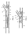
stent delivery system 10 constructed in accordance with the present invention is shown inFIG. 1 .Stent delivery system 10 generally comprises an elongatemain catheter shaft 12 extending from aproximal end 14 to adistal end 16. As best seen inFIG. 2 ,distal end 16 has a bifurcated tip structure with two branch portions, a mainvessel branch portion 18 and aside branch sheath 20 that branch off ofmain catheter shaft 12. Abifurcated balloon 26 is attached to mainvessel branch portion 18 adjacent thedistal end 16 and comprises first andsecond branch portions First branch portion 27 ofballoon 26 comprises an elongateinflatable portion 28.Second branch portion 30 ofballoon 26 comprises a second inflatable portion or auxiliaryinflatable portion 32.Second branch portion 30 includes an inflation lumen that branches off fromfirst branch portion 27 proximally from theballoon 26 and extends substantially adjacent elongateinflatable portion 28. The distal end ofsecond branch portion 30 is attached tofirst branch portion 27 at a location distally from theballoon 26. In one preferred embodiment, the distal end ofbranch portion 30 is fixedly attached distally ofballoon 26 in order to prevent at least the secondinflatable portion 32 from moving around thefirst branch portion 27, although in embodiments known in the art it may be removably attached. - In a preferred embodiment, first
inflatable portion 28 is generally cylindrical and extends coaxially along mainvessel branch portion 18. Secondinflatable portion 32 may have a shape and size adapted to extend into the branch vessel as shown and described herein. For example,portion 32 may have a generally offset configuration and may be positioned adjacent or in abutting relation with respect to elongateinflatable portion 28. - The first and second inflatable portions can have varied shapes, sizes and positioning in accordance with the principles of the invention. For example, in alternative design variations, accurate sizing and positioning of the inflatable portions relative to the vessel may be achieved.
- According to the present invention, the inflatable portions, or balloons, can be constructed of any suitable material. For example, the balloons may be constructed of an appropriate polymeric material. Particular examples include the polyamide family, or the polyamide blend family, polyethylene (PE), polyethylene terephthalate (PET), polyurethanes, polyamides, and polyamide blends such as PBAX. The compliance of the first
inflatable portion 28 and the secondinflatable portion 32 can be the same or different. In one preferred embodiment, secondinflatable portion 32 is longitudinally positioned at a generally central location relative to the firstinflatable portion 28. In alternate embodiments, secondinflatable portion 32 may be positioned at any position adjacent firstinflatable portion 28. - In a preferred embodiment,
balloon branch portions common inflation lumen 34.Inflation lumen 34 can be conventional, and extend from a portion of the stent delivery system which always remains outside of the patient (not pictured).Inflation lumen 34 extends distally into each of first andsecond branch portions inflation lumen 34 is in fluid communication with the interiors of firstinflatable portion 28 and secondinflatable portion 32. Thusinflation lumen 34 is used to supply pressurized inflation fluid to firstinflatable portion 28 and secondinflatable portion 32 when it is desired to inflateballoon 26.Inflation lumen 34 is also used to drain inflation fluid from firstinflatable portion 28 and secondinflatable portion 32 when it is desired to deflate the balloon. First and second inflatable portions are initially deflated when directing the stent delivery device to the bifurcation lesion in a patient. In this embodiment, theinflation lumen 34 inflatesinflatable portions branch balloon portions inflatable portions inflatable portion 28 is inflated first, followed by the inflation of thesecond portion 32. - First
main guidewire lumen 22 extends through mainvessel branch portion 18 and firstinflatable portion 28. Althoughfirst guidewire lumen 22 extends through firstinflatable portion 28 in the embodiment depicted inFIGS. 1-2 , it is distinct frominflation lumen 34 and is not in fluid communication with the interior ofballoon 26 as shown. Preferably, thefirst guidewire lumen 22 extends distally of firstinflatable portion 28 and has an open distal end. Alternatively,guidewire lumen 22 can extend throughbranch portion 30. - In the embodiment depicted in
FIGS. 1-2 , anoptional side sheath 20 is illustrated which does not include an inflatable balloon. Although in alternateembodiments side sheath 20 could include an inflatable portion, as described for example in co-pendingU.S. Patent Application No. 10/644,550 entitled "Stent With a Protruding Branch Portion For Bifurcated Vessels".Side sheath 20 is exterior to and distinct frominflation lumen 34 and thus is also not in fluid communication with the interior ofballoon 26 as shown. As shown in the embodiment ofFIGS. 1-2 ,side sheath 20 preferably extends distally ofballoon 26, and may include a proximalopen end 37 at any point along the length of the stent delivery system and a distalopen end 39.Side sheath 20 can be of the type as described inU.S. Patent No. 6,325,826 to Vardi, et al. , for example, and in operation theside sheath 20 can extend through a branch access hole of the stent. - With reference to
FIGS. 3-6 , an exemplary manner of practicing the invention will now be discussed. Referring toFIGS. 3 and5 , the delivery system is shown in relation to an exemplary body lumen adjacent ablood vessel bifurcation 40 usually comprised of plaque and thedelivery system 10 is shown without a stent mounted thereon (FIGS. 3 and5 ).Figs. 4 and6 show thestent delivery system 10 with astent 50 mounted thereon. -
Bifurcation 40 includes amain vessel 42 and abranch vessel 44.Illustrative obstructions 46 located withinbifurcation 40 may span or at least partially obstructmain vessel 42 and a proximalportion branch vessel 44. Generally,stent delivery system 10 may be threaded over a first main guidewire placed in the main vessel to guide the delivery system to the treatment site. More specifically, the proximal end offirst guidewire 36 is threaded into the distal open end of themain guidewire lumen 22 and the delivery system is tracked to a position at or nearbifurcation 40, as depicted inFIG. 3 . Second guidewire 38 (FIG. 5 ) is then threaded intostent delivery system 10 from the proximal end of the delivery system. More specifically,second guidewire 38 is threaded into the openproximal end 37 ofside sheath 20, and may extend therefrom through the opendistal end 39 ofside sheath 20, as depicted inFIG. 5 . Alternatively,second guidewire 38 can be resting dormant on the inside of the side sheath, and when the system is proximal thebifurcation 40, it can be advanced out ofside sheath 20 intoside branch vessel 44. The systems in accordance with the principles of the invention may be used in over-the-wire or rapid exchange systems, which may include rapid exchange on either or both of the side sheath or main catheter. Rapid exchange is described in one exemplary embodiment inUS2003/0181923 to Vardi et al., published September 25, 2003 . - In one embodiment, the
stent delivery system 10 is positioned nearbifurcation 40, and with the distal end 16 (FIG. 1 ) positioned near side branch vessel 44 (FIGS. 3-6 ),second guidewire 38 is advanced intoside branch vessel 44 fromside sheath 20. Then, the first and second inflatable portions ofballoon 26 are positioned adjacent the opening ofside branch vessel 44 such that auxiliaryinflatable side portion 32 ofbifurcated balloon 26 is aligned with side branch vessel. In one exemplary embodiment, alignment may be achieved using markers, as described inU.S. Patent No. 6,692,483 to Vardi, et al. Second guidewire 38 remains inside branch sheath 20, and thedistal end 16 ofsystem 10 remains inmain vessel 42. First guidewire 36 remains withinfirst guidewire lumen 22, and may be further advanced and positioned inmain branch vessel 42. - Once the system is properly positioned, pressurized fluid is supplied to first and second
inflatable portions balloon 26 to dilate the body lumen and expand a stent mounted thereon (FIG. 6 ). Preferably, theinflatable portion 28 expands the main body of the stent andinflatable portion 32 expands the side (opening) and expandable branch structure of the stent, as discussed in more detail with reference toFIG. 6 . Afterinflatable portions balloon 26 is deflated by draining the inflation fluid viainflation lumen 34. This allows theinflatable portions vessel 42. - Referring now to
FIGS. 4 and6 , one preferred embodiment is shown withstent delivery system 10 and anexemplary stent 50 mounted on the exterior ofdistal end 16 of the stent delivery system.Stent 50 includes anextendible branch portion 52 configured to extend into a branch vessel as discussed in co-pendingU.S. Application No. 10/644,550 , entitled "Stent with Protruding Branch Portion for Bifurcated Vessels". The secondinflatable portion 32 may be configured and positioned to deploy the outwardly expanding stent elements orbranch portion 52 and may be positioned adjacent to thebranch portion 52, or into a side branch access opening in the stent. As shown inFIG. 6 , when first and secondinflatable portions stent 50 to expand in themain vessel 42 and thebranch portion 52 ofstent 50 to be pushed or extended into thebranch vessel 44. Upon inflation of theballoon 26, the secondinflatable portion 32 expands and extends thebranch portion 52 toward the branch vessel to open and support the entrance or ostium of the side branch artery. This would occur simultaneously when the balloons share a common inflation lumen but could be sequentially if separate inflation lumens are used. Although a bifurcated balloon is depicted, as shown, more than two inflatable portions or more than two balloons may be utilized with the present invention. - As illustrated, for example, in
FIGS. 5 and 6 , the first andsecond branch portions branch portions -
FIG. 7 is an enlarged perspective view of the auxiliaryinflatable side portion 32 ofbifurcated balloon 26, which is referred to in the previous embodiments depicted inFIGS. 1-6 . According to this embodiment, thecentral portion 33 of the auxiliaryinflatable side portion 32 extends in a generally equidistant manner from the longitudinal axis A, and at an angle of up to about 90° relative to longitudinal axis A, but other angles are contemplated. As illustrated inFIG. 7 , the auxiliaryinflatable side portion 32 can have a generically sphericalcentral portion 33 which is connected to aproximal shaft 41, as well adistal shaft 43. The components of the auxiliaryinflatable side portion 32 may be sized appropriately, as will be readily apparent to those skilled in the art. The centralspherical portion 33 can be provided with a suitable inflated diameter D. The diameter D can vary according to various factors known to those skilled in the art. According to a non-limiting, exemplary embodiment, the diameter D can be on the order of a few millimeters. For example, the diameter D is on the order of about 1.5-6.0mm and, preferably, on the order of about 3.34-3.36mm. -
FIG. 8 illustrates an alternative auxiliary inflatableside portion construction 132. According to this embodiment, thecentral portion 133 of the auxiliaryinflatable side portion 132 extends in a generally equidistant manner from the longitudinal axis A, and at an angle of up to about 90° relative to longitudinal axis A, but other angles are contemplated. As illustrated inFIG.8 , theballoon 132 comprises a generally ellipticalcentral portion 133, as well as aproximal shaft portion 141, and distal shaft 143 connected thereto. As with the previous embodiment, the various components of theballoon 132 may be sized as appropriate within appropriate dimensional ranges, as determined by those skilled in the art. The ellipticalcentral section 133 of theballoon 132 is provided with major and minor diameters, D1 and D2, respectively, as illustrated inFIG.7 . According to non-limiting exemplary embodiments, the elliptical central section may be shaped such that the ratio D2/D1 is on the order of about 0.8. According to further exemplary non-limiting embodiments, the major diameter D1 is preferably on the order of about 3.65-3.85mm and can range from 1.5-6mm, while the minor diameter D2 is smaller than D1 and is preferably on the order of about 2.9-3.1mm. -
FIG.9 illustrates yet a further embodiment of auxiliaryinflatable side portion 232 ofbifurcated balloon 26 constructed according to the principles of the present invention. According to this embodiment, thecentral portion 232 is offset relative to the longitudinal axis A and preferably extends toward and/or into thebranch vessel 44. Thecentral portion 232 may extend at an angle of up to about 90° relative to longitudinal axis A, but other angles are contemplated. As illustrated inFIG. 9 , the auxiliaryinflatable side portion 232 ofballoon 26 comprises an offset central bulbous or generallyspherical portion 233, with aproximal shaft portion 241 anddistal shaft portion 243 connected thereto via aproximal transition section 241T anddistal transition 243T, respectively. As with the previous embodiments, the various components of the auxiliaryinflatable side portion 232 ofballoon 26 can be sized as appropriate, and as readily determined by those skilled in the art. According to exemplary, non-limiting embodiments, the auxiliaryinflatable side portion 232 ofballoon 26 can be configured such that the central offsetportion 233 is provided with a radius of curvature R which is on the order of about .50-3.0mm. -
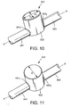
FIG. 10 illustrates yet another alternative embodiment for an auxiliaryinflatable side portion 332 ofbifurcated balloon member 26. According to this embodiment, thecentral portion 332 is offset relative to the longitudinal axis A and preferably extends toward and/or into the branch vessel 44 (not shown). Thecentral portion 332 may extend at an angle of up to about 90° relative to longitudinal axis A, but other angles are contemplated. As shown inFIG. 10 , the auxiliaryinflatable side portion 332 is configured such that it comprises a generally offset elliptical and cylindricalcentral section 333, withproximal shaft portions 341 anddistal shaft portions 343 connected thereto viaproximal transition section 341T anddistal transition portion 343T, respectively. The offsetcentral section 333 is preferably configured such that it comprised a first diameter D1 and second diameter D2 wherein D1 and D2 have different values (D1 ≠ D2). The dimensions of the various constituent components of the auxiliaryinflatable side portion 332 can be determined by those skilled in the art. According to exemplary non-limiting embodiments, the auxiliaryinflatable side portion 332 can be configured such that it is provided with first and second diameters such that the ratio D2/D1 is on the order of about 0.25-4.0mm. According to further, non-limiting examples, the auxiliaryinflatable side portion 332 can be configured such that it is provided with a first diameter D1 which has dimensions on the order of about 1.5-6.0mm and, preferably about 2.7-2.9mm, and a second diameter D2 which has dimensions on the order of about 1.5-6.0mm, and preferably about 2.1-2.3mm. -
FIG. 11 illustrates yet another alternative embodiment of an auxiliaryinflatable side portion 432 ofbifurcated balloon 26. According to this embodiment, thecentral portion 432 is offset relative to the longitudinal axis A and preferably extends toward and/or into the branch vessel 44 (not shown). Thecentral portion 432 may extend at an angle of up to about 90° relative to longitudinal axis A, but other angles are contemplated. The auxiliaryinflatable side portion 432 is configured such that it comprises an offset generally cylindricalcentral section 433 having aproximal shaft portion 441 and adistal shaft portion 443 connected thereto via proximaltransition shaft portion 441T anddistal transition portion 443T, respectively. The various constituent components of theballoon 432 can be configured with relative dimensions which can be ascertained by those skilled in the art. According to exemplary, non-limiting examples, theballoon 432 can be configured such that it is provided with an offset generally cylindricalcentral section 433 having a diameter D which is on the order of about 1.5-6.0mm -
FIGS. 12-15 illustrate further alternative embodiments of the present invention which can be utilized in the treatment of branch arteries, including incorporation into stent-delivery systems of the type previously described. The balloons depicted in the embodiments ofFIGS. 12-15 can be referred to as "herniated" balloon configurations that function in a manner similar to the embodiments described above. The herniated balloon configuration is characterized by having a generally cylindrical shape in an unexpanded configuration, and a generally cylindrical shape with a generally hemispherical appendage that inflates outwardly relative to the longitudinal axis of the balloon toward the branch artery in an expanded state or configuration. This protrusion can be referred to as a herniation, bulge, protrusion, or extension. The particular shape, size, and configuration of the balloon and the herniations illustrated herein are exemplary, and may be modified from that explicitly shown and described. The expandable herniation, bulge, protrusion, or extension can be expandable towards the entrance of side branch (e.g. - 44,FIG.3 ) over a suitable dimension, such as 1-4mm. - The embodiments of the balloons depicted in
FIGS. 12-15 can be utilized in a manner similar to that which has been described in connection with previously illustrated embodiments (see, e.g. -FIGS. 1-6 ). - With regard to the embodiments depicted in
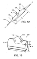
FIGS. 12-15 , it should be understood that the herniated balloon constructions depicted therein can be utilized as one or more of the first and second inflatable portions of a bifurcated balloon (e.g. 26,FIGS. 1-6 ). Alternatively, the herniated balloon constructions can be utilized in place of a bifurcated-type balloon. In other words, the herniated balloon can be utilized by itself instead of a balloon construction which relies upon distinct first and second inflatable portions. An exemplary embodiment of aherniated balloon catheter 526 is illustrated inFIG. 12 . In the illustrated embodiment, the herniatedballoon catheter 526 comprises an elongatedinflatable portion 528 and a herniation, bulge, protrusion, orextension 532 therewith. In the embodiment ofFIG. 12 the balloon catheter further includes alumen 534 which can serve to communicate pressure for inflation of theballoon catheter 526, and provide a passage way for a guide wire, etc. - The particular configuration and dimensions of the
balloon catheter 526 can vary according to a number of factors. For purposes of illustration only, certain suitable, but non-limiting, dimensions of various components of theballoon catheter 526 will now be described. Theballoon catheter 526 can be provided with a length dimension L1 which is about 4-100mm. The balloon can be provided with an outside diameter OD1 which is on the order of about 1-10mm, and theherniation 532 can be provided with a radius of curvature R1 which is about 0.5-3mm. -
FIG. 13 illustrates a portion 526' of a herniated balloon catheter, which includes a herniation 533'. According to further non-limiting examples, the balloon portion 526' can be provided with the following suitable dimensions: outside diameter OD2 of 1-10mm; a length dimension L2 of about 4-100mm; a wall thickness dimension T2 of about 0.003-0.005mm and a radius of curvature R2 of the herniated portion 533' of about 0.05-3mm. - Another alternative herniated balloon construction is shown in
FIG. 14 , where the herniatedballoon portion 526" is provided with an alternatively configuredherniation 533". Illustrative and non-limiting examples of suitable dimensions according to this embodiment include: an outside diameter OD3 (FIG. 15 ) of about 1-10mm; a length dimension L3 of about 4-100mm; a height dimensions H of theherniation 533" of about 1-6mm; and a radius of curvature R3 of theherniation 533" of about 0.5-3mm; and a wall thickness of the herniatedballoon catheter portion 526" of about 0.01mm. - Although the
herniation FIGS. 12-15 are shown as being centrally located on the herniatedballoon catheter 526 or herniatedballoon catheter portions 526', 526", it should be noted that theherniation 533, 533', and/or 533" maybe located at any desired position along the length of the balloon. For example, once associated with a stent, it can preferably be placed such that it corresponds to the location along the middle 1/3 of the stent. - The
balloon 526, 526', and/or 526" can be constructed of any suitable material such as those previously disclosed herein. In addition, theballoon 526, 526', and/or 526" can be constructed of a composite material. Suitable materials include a combination of elastomeric and semi to non-compliant materials such as: urethane; silicone; nylon; latex; (elastomeric) polyethylene hytrel pebax polyaryletherthketone; polyoxymethylene; polyamide; polyester thermoplastic polyetheretherkatone; and polypropylene (semi non-compliant). Theballoon 526, 526', and/or 526" can be also be constructed by combining the above-disclosed materials with woven textile materials such as Kevlar, silk, cotton, wool, etc. This can be accomplished by winding or weaving a textile material onto a rod that has the shape of the desired herniated balloon. The polymer component of the composite is then extruded or dip-coated over the rod. This composite structure is then cured, heat set, or adhesively fused together. The rod is then removed and the remaining shape comprises the herniatedballoon 526, 526', and/or 526". - The
herniation 533, 533', and/or 533" can be provided by adding an appendage to a conventional balloon by using a molded collar or adhesively attaching an object to the surface of the balloon, or by using a mound of adhesive to create the herniation. - The
balloon 526, 526', and/or 526" can be constructed by molding three small balloons and attaching them in tandem. The central balloon comprising the desired shape of the herniation. These balloons would share a common inflation port. When the balloons are inflated, the center balloon expands in the desired manner to form the herniation. - According to further aspects of the present invention, more than two inflatable portions or more than two balloons may be utilized. For example, as shown in
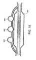
FIGS. 16-18 , the balloon may include a plurality of second inflatable portions. In this regard, a user may be able to treat multiple bifurcations with a single device. Such a configuration, may also eliminate the need for a secondary positioning lumen (side sheath 20) and reduce the profile of the system. As shown inFIGS. 16-17 , in one exemplary embodiment,balloon 626 includes fourinflatable portions 662 positioned radially around a firstinflatable portion 660. In an alternate embodiment, shown inFIG. 18 , a plurality ofinflatable balloon portions 662 are spaced longitudinally adjacent one side of firstinflatable portion 660. - Referring to
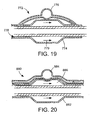
FIG. 19 , a cross-sectional view of an alternative embodiment of aballoon 772 is shown.Balloon 772 includes a maininflatable portion 774 and further extends into secondaryinflatable portion 776.Lumen 778 can be of various diameters, compliances, and materials to control the timing and size of the secondaryexpandable portion 776 upon inflation. In one embodiment, secondexpandable portion 776 may deploy subsequent to mainexpandable portion 774. Such a time delay may be achieved, for example, using a smaller diameter inflation lumen leading up to secondaryexpandable portion 776 since the inflation fluid travels alongpath 779 first through the mainexpandable portion 774 and then on to secondaryexpandable portion 776. In this regard, delivery system 770, may permit sequential deployment of two expandable portions using a single inflation port. - Referring to
FIG. 20 , a cross-sectional view of an alternative embodiment of aballoon 880 is shown in an expanded state.Balloon 880 comprises a maininflatable portion 882 and an auxiliaryinflatable portion 884. Mainexpandable portion 882 has an indentation or cavity configured and dimensioned to received a portion of auxiliaryexpandable portion 884 whenballoon 880 is inflated. For example, as shown inFIG. 20 auxiliary inflatable portion is generally spherically shaped and when inflated,cavity 886 is aligned and positioned to accommodate a portion of the spherical shape. In this regard, whenballoon 880 is inflated, the inflated balloon has the approximate peripheral shape of a cylinder with a hemispherical protrusion. In use, the auxiliaryexpandable portion 884 is configured to deploy or extend outwardly deployable elements of a stent into a bifurcation. In operation, when both expandable portions are inflated, such a balloon configuration allows for varying expansion capabilities and preferably prevents the region of a stent adjacent secondinflatable portion 884 from over expanding into the bifurcated region. As a result, the possibility of causing trauma to the vessel is preferably limited. - While the invention has been described in conjunction with specific embodiments and examples thereof, it is evident that many alternatives, modifications and variations will be apparent to those skilled in the art upon reading the present disclosure. Accordingly, it is intended to embrace all such alternatives, modifications and variations that fall within the scope of the appended claims. Furthermore, features of each embodiment can be used in whole or in part in other embodiments.
Claims (20)
- An apparatus (10) for treatment of a bifurcation of a body lumen, the bifurcation comprising a main vessel and a branch lumen vessel, the system (10) comprising:a catheter for insertion into said body lumen, the catheter having a distal region (16) and a proximal region (14), the distal region (16) of the catheter including a main vessel branch portion (18) including a first balloon branch portion (27) and a second balloon branch portion (30), the second balloon branch portion (30) including an inflatable portion (32) adapted to extend toward the branch vessel, the second balloon branch portion (30) including a proximal shaft portion (41) connected to a proximal end of the inflatable portion (32) and to the first balloon branch portion (27), the second balloon branch portion (30) including a distal shaft portion (43) permanently connected to a distal end of the inflatable portion (32) and to the first balloon branch portion (27), andwherein the first balloon branch portion (27) and the second balloon branch portion (30) each have a longitudinal axis, the longitudinal axis of the first balloon branch portion (27) is substantially parallel to the longitudinal axis of the second balloon branch portion (30).
- The apparatus of claim 1, wherein the inflatable portion (32) of the second balloon branch portion (30) is generally spherical.
- The apparatus of claim 1, wherein the inflatable portion (32) of the second balloon branch portion (30) is generally elliptical and comprises a major and minor axis.
- The apparatus of claim 1, wherein the inflatable portion (32) of the second balloon branch portion (30) is generally in the form of an offset bulbous shape.
- The apparatus of claim 1, wherein the inflatable portion (32) of the second balloon branch portion (130) is generally in the form of an offset elliptical cylinder.
- The apparatus of claim 1, wherein the inflatable portion (32) of the second balloon branch portion (30) is generally in the form of an offset cylinder.
- The apparatus of claim 1, wherein the second balloon branch portion (30) comprises a plurality of inflatable portions.
- The apparatus of claim 7, wherein said plurality comprises more than two inflatable portions.
- The apparatus of claim 8, wherein the inflatable portions are circumferentially spaced about the first balloon branch portion (27).
- The apparatus of claim 8, wherein the inflatable portions are longitudinally spaced along the first balloon branch portion (27).
- The apparatus of claim 1, wherein the first and second balloon branch portions share a common inflation lumen.
- The apparatus of claim 1, wherein the catheter includes a bifurcated distal end (16) including the main vessel branch (18) and a second branch (20),
wherein the first balloon branch portion (27) includes an inflatable portion;
wherein the inflatable portion of the first balloon (27) branch portion has a generally cylindrical shape when inflated and the inflatable portion of the second balloon branch portion has a generally offset bulbous shape when inflated. - The apparatus of claim 12, further comprising:a stent mounted on the mains vessel branch portion, the stent including a side branch access hole.
- The apparatus of claim 13, wherein the stent includes an extendible branch portion configured and dimensioned to extend into a branch vessel upon expansion of the stent.
- The apparatus of claim 1 further comprising a stent disposed on the balloon, the stent having an opening including an outwardly expandable portion, the opening aligned with the inflatable portion of the second balloon branch, wherein expansion of the inflatable portion of the second balloon branch causes the outwardly expandable portion to extend toward the branch vessel.
- The apparatus of claim 15, wherein the first balloon branch and the second balloon branch each have a longitudinal axis, the longitudinal axis of the first balloon branch portion being substantially parallel to the longitudinal axis of the second balloon branch portion.
- The apparatus of claim 15, wherein the inflatable portion is generally in the form of an elliptical cylinder.
- The apparatus of claim 15, wherein the inflatable portion is generally in the form of an offset cylinder.
- The apparatus of claim 15, wherein the inflatable portion is generally in the form of an offset bulbous portion.
- The apparatus of claim 15, wherein the second branch portion comprises a plurality of inflatable portions.
Priority Applications (1)
| Application Number | Priority Date | Filing Date | Title |
|---|---|---|---|
| EP09165469A EP2111825B1 (en) | 2003-07-18 | 2004-06-25 | Catheter balloon systems and balloon with herniation |
Applications Claiming Priority (6)
| Application Number | Priority Date | Filing Date | Title |
|---|---|---|---|
| US48800603P | 2003-07-18 | 2003-07-18 | |
| US51887003P | 2003-11-12 | 2003-11-12 | |
| US54777804P | 2004-02-27 | 2004-02-27 | |
| US54886804P | 2004-03-02 | 2004-03-02 | |
| US10/834,066 US7655030B2 (en) | 2003-07-18 | 2004-04-29 | Catheter balloon systems and methods |
| PCT/US2004/017425 WO2005014077A2 (en) | 2003-07-18 | 2004-06-25 | Catheter balloon systems and methods |
Related Child Applications (1)
| Application Number | Title | Priority Date | Filing Date |
|---|---|---|---|
| EP09165469A Division EP2111825B1 (en) | 2003-07-18 | 2004-06-25 | Catheter balloon systems and balloon with herniation |
Publications (3)
| Publication Number | Publication Date |
|---|---|
| EP1663340A2 EP1663340A2 (en) | 2006-06-07 |
| EP1663340A4 EP1663340A4 (en) | 2007-09-19 |
| EP1663340B1 true EP1663340B1 (en) | 2009-08-05 |
Family
ID=34069439
Family Applications (2)
| Application Number | Title | Priority Date | Filing Date |
|---|---|---|---|
| EP04754109A Not-in-force EP1663340B1 (en) | 2003-07-18 | 2004-06-25 | Catheter balloon systems |
| EP09165469A Not-in-force EP2111825B1 (en) | 2003-07-18 | 2004-06-25 | Catheter balloon systems and balloon with herniation |
Family Applications After (1)
| Application Number | Title | Priority Date | Filing Date |
|---|---|---|---|
| EP09165469A Not-in-force EP2111825B1 (en) | 2003-07-18 | 2004-06-25 | Catheter balloon systems and balloon with herniation |
Country Status (8)
| Country | Link |
|---|---|
| US (2) | US7655030B2 (en) |
| EP (2) | EP1663340B1 (en) |
| JP (1) | JP4596332B2 (en) |
| AT (1) | ATE438426T1 (en) |
| CA (1) | CA2521481A1 (en) |
| DE (1) | DE602004022428D1 (en) |
| ES (1) | ES2330525T3 (en) |
| WO (1) | WO2005014077A2 (en) |
Families Citing this family (105)
| Publication number | Priority date | Publication date | Assignee | Title |
|---|---|---|---|---|
| US6325826B1 (en) | 1998-01-14 | 2001-12-04 | Advanced Stent Technologies, Inc. | Extendible stent apparatus |
| US6835203B1 (en) * | 1996-11-04 | 2004-12-28 | Advanced Stent Technologies, Inc. | Extendible stent apparatus |
| ES2273363T3 (en) * | 1996-11-04 | 2007-05-01 | Advanced Stent Technologies, Inc. | DOUBLE EXTENSIBLE STENT. |
| US7220275B2 (en) * | 1996-11-04 | 2007-05-22 | Advanced Stent Technologies, Inc. | Stent with protruding branch portion for bifurcated vessels |
| US7341598B2 (en) | 1999-01-13 | 2008-03-11 | Boston Scientific Scimed, Inc. | Stent with protruding branch portion for bifurcated vessels |
| US6599316B2 (en) * | 1996-11-04 | 2003-07-29 | Advanced Stent Technologies, Inc. | Extendible stent apparatus |
| US8257425B2 (en) * | 1999-01-13 | 2012-09-04 | Boston Scientific Scimed, Inc. | Stent with protruding branch portion for bifurcated vessels |
| US7655030B2 (en) * | 2003-07-18 | 2010-02-02 | Boston Scientific Scimed, Inc. | Catheter balloon systems and methods |
| DE60045193D1 (en) * | 1999-01-27 | 2010-12-16 | Boston Scient Ltd | Bifurkationsstenteinführsystem |
| AU7714500A (en) * | 1999-09-23 | 2001-04-24 | Advanced Stent Technologies, Inc. | Bifurcation stent system and method |
| AU2002250189A1 (en) | 2001-02-26 | 2002-09-12 | Scimed Life Systems, Inc. | Bifurcated stent and delivery system |
| US7147661B2 (en) | 2001-12-20 | 2006-12-12 | Boston Scientific Santa Rosa Corp. | Radially expandable stent |
| US20060253480A1 (en) * | 2002-04-06 | 2006-11-09 | Staples Peter E | Collaborative design process for a design team, outside suppliers, and outside manufacturers |
| KR100893070B1 (en) * | 2002-09-19 | 2009-04-17 | 엘지전자 주식회사 | Method and apparatus for providing and receiving multicast service in a radio communication system |
| US7717953B2 (en) | 2004-10-13 | 2010-05-18 | Tryton Medical, Inc. | Delivery system for placement of prosthesis at luminal OS |
| US8109987B2 (en) * | 2003-04-14 | 2012-02-07 | Tryton Medical, Inc. | Method of treating a lumenal bifurcation |
| US7972372B2 (en) * | 2003-04-14 | 2011-07-05 | Tryton Medical, Inc. | Kit for treating vascular bifurcations |
| US8083791B2 (en) * | 2003-04-14 | 2011-12-27 | Tryton Medical, Inc. | Method of treating a lumenal bifurcation |
| US7758630B2 (en) | 2003-04-14 | 2010-07-20 | Tryton Medical, Inc. | Helical ostium support for treating vascular bifurcations |
| US7731747B2 (en) * | 2003-04-14 | 2010-06-08 | Tryton Medical, Inc. | Vascular bifurcation prosthesis with multiple thin fronds |
| US8298280B2 (en) * | 2003-08-21 | 2012-10-30 | Boston Scientific Scimed, Inc. | Stent with protruding branch portion for bifurcated vessels |
| US7766951B2 (en) * | 2004-03-04 | 2010-08-03 | Y Med, Inc. | Vessel treatment devices |
| US9050437B2 (en) | 2004-03-04 | 2015-06-09 | YMED, Inc. | Positioning device for ostial lesions |
| US7780715B2 (en) | 2004-03-04 | 2010-08-24 | Y Med, Inc. | Vessel treatment devices |
| US8007528B2 (en) * | 2004-03-17 | 2011-08-30 | Boston Scientific Scimed, Inc. | Bifurcated stent |
| JP5054524B2 (en) | 2004-06-08 | 2012-10-24 | アドバンスド ステント テクノロジーズ, インコーポレイテッド | Stent with protruding branch for branch pipe |
| EP1796584A1 (en) | 2004-07-27 | 2007-06-20 | The Cleveland Clinic Foundation | Apparatus for treating atherosclerosis |
| US9427340B2 (en) * | 2004-12-14 | 2016-08-30 | Boston Scientific Scimed, Inc. | Stent with protruding branch portion for bifurcated vessels |
| WO2006074476A2 (en) * | 2005-01-10 | 2006-07-13 | Trireme Medical, Inc. | Stent with self-deployable portion |
| US9101500B2 (en) * | 2005-01-10 | 2015-08-11 | Trireme Medical, Inc. | Stent with self-deployable portion having wings of different lengths |
| US7850645B2 (en) * | 2005-02-11 | 2010-12-14 | Boston Scientific Scimed, Inc. | Internal medical devices for delivery of therapeutic agent in conjunction with a source of electrical power |
| US7922754B2 (en) | 2005-04-18 | 2011-04-12 | Trireme Medical, Inc. | Apparatus and methods for delivering prostheses to luminal bifurcations |
| US7862601B2 (en) * | 2005-05-23 | 2011-01-04 | Incept Llc | Apparatus and methods for delivering a stent into an ostium |
| US8608789B2 (en) | 2005-05-24 | 2013-12-17 | Trireme Medical, Inc. | Delivery system for bifurcation stents |
| US8317855B2 (en) * | 2005-05-26 | 2012-11-27 | Boston Scientific Scimed, Inc. | Crimpable and expandable side branch cell |
| US20060271161A1 (en) * | 2005-05-26 | 2006-11-30 | Boston Scientific Scimed, Inc. | Selective treatment of stent side branch petals |
| US8480728B2 (en) * | 2005-05-26 | 2013-07-09 | Boston Scientific Scimed, Inc. | Stent side branch deployment initiation geometry |
| US7731741B2 (en) | 2005-09-08 | 2010-06-08 | Boston Scientific Scimed, Inc. | Inflatable bifurcation stent |
| US8038706B2 (en) * | 2005-09-08 | 2011-10-18 | Boston Scientific Scimed, Inc. | Crown stent assembly |
| US8043366B2 (en) * | 2005-09-08 | 2011-10-25 | Boston Scientific Scimed, Inc. | Overlapping stent |
| US8231669B2 (en) * | 2005-09-22 | 2012-07-31 | Boston Scientific Scimed, Inc. | Tether guided stent side branch |
| US20070067023A1 (en) * | 2005-09-22 | 2007-03-22 | Boston Scientific Scimed, Inc. | Tether guided stent side branch |
| US7776079B2 (en) | 2005-10-31 | 2010-08-17 | Boston Scientific Scimed, Inc. | Conical balloon for deployment into side branch |
| US8192477B2 (en) | 2005-11-14 | 2012-06-05 | Boston Scientific Scimed, Inc. | Twisting bifurcation delivery system |
| US20070112418A1 (en) * | 2005-11-14 | 2007-05-17 | Boston Scientific Scimed, Inc. | Stent with spiral side-branch support designs |
| US7766893B2 (en) * | 2005-12-07 | 2010-08-03 | Boston Scientific Scimed, Inc. | Tapered multi-chamber balloon |
| US8343211B2 (en) * | 2005-12-14 | 2013-01-01 | Boston Scientific Scimed, Inc. | Connectors for bifurcated stent |
| US8435284B2 (en) * | 2005-12-14 | 2013-05-07 | Boston Scientific Scimed, Inc. | Telescoping bifurcated stent |
| US7540881B2 (en) | 2005-12-22 | 2009-06-02 | Boston Scientific Scimed, Inc. | Bifurcation stent pattern |
| US8821561B2 (en) * | 2006-02-22 | 2014-09-02 | Boston Scientific Scimed, Inc. | Marker arrangement for bifurcation catheter |
| US20070208415A1 (en) * | 2006-03-06 | 2007-09-06 | Kevin Grotheim | Bifurcated stent with controlled drug delivery |
| US20070208411A1 (en) * | 2006-03-06 | 2007-09-06 | Boston Scientific Scimed, Inc. | Bifurcated stent with surface area gradient |
| US7833264B2 (en) * | 2006-03-06 | 2010-11-16 | Boston Scientific Scimed, Inc. | Bifurcated stent |
| US20070208419A1 (en) * | 2006-03-06 | 2007-09-06 | Boston Scientific Scimed, Inc. | Bifurcation stent with uniform side branch projection |
| US8298278B2 (en) * | 2006-03-07 | 2012-10-30 | Boston Scientific Scimed, Inc. | Bifurcated stent with improvement securement |
| US20070233233A1 (en) * | 2006-03-31 | 2007-10-04 | Boston Scientific Scimed, Inc | Tethered expansion columns for controlled stent expansion |
| US7901378B2 (en) * | 2006-05-11 | 2011-03-08 | Y-Med, Inc. | Systems and methods for treating a vessel using focused force |
| US8486025B2 (en) | 2006-05-11 | 2013-07-16 | Ronald J. Solar | Systems and methods for treating a vessel using focused force |
| US20070270935A1 (en) * | 2006-05-18 | 2007-11-22 | Abbott Laboratories | Dual balloon catheter and deployment of same |
| EP2051673A2 (en) | 2006-06-23 | 2009-04-29 | Boston Scientific Limited | Bifurcated stent with twisted hinges |
| US8029558B2 (en) * | 2006-07-07 | 2011-10-04 | Abbott Cardiovascular Systems, Inc. | Stent and catheter assembly and method for treating bifurcations |
| US8177829B2 (en) * | 2006-08-23 | 2012-05-15 | Boston Scientific Scimed, Inc. | Auxiliary balloon catheter |
| US8216267B2 (en) * | 2006-09-12 | 2012-07-10 | Boston Scientific Scimed, Inc. | Multilayer balloon for bifurcated stent delivery and methods of making and using the same |
| US8454681B2 (en) * | 2006-09-13 | 2013-06-04 | Boston Scientific Scimed, Inc. | Bifurcation delivery systems and methods |
| US8608790B2 (en) * | 2006-10-06 | 2013-12-17 | Boston Scientific Scimed, Inc. | Bifurcation catheter and method |
| US7951191B2 (en) | 2006-10-10 | 2011-05-31 | Boston Scientific Scimed, Inc. | Bifurcated stent with entire circumferential petal |
| KR20130095317A (en) * | 2006-10-22 | 2013-08-27 | 이데브 테크놀로지스, 아이엔씨. | Devices and methods for stent advancement |
| US7871396B2 (en) * | 2006-10-30 | 2011-01-18 | Boston Scientific Scimed, Inc. | Bifurcation catheter assembly and method |
| US8206429B2 (en) | 2006-11-02 | 2012-06-26 | Boston Scientific Scimed, Inc. | Adjustable bifurcation catheter incorporating electroactive polymer and methods of making and using the same |
| US8398695B2 (en) * | 2006-11-03 | 2013-03-19 | Boston Scientific Scimed, Inc. | Side branch stenting system using a main vessel constraining side branch access balloon and side branching stent |
| US8414611B2 (en) * | 2006-11-03 | 2013-04-09 | Boston Scientific Scimed, Inc. | Main vessel constraining side-branch access balloon |
| US7842082B2 (en) | 2006-11-16 | 2010-11-30 | Boston Scientific Scimed, Inc. | Bifurcated stent |
| US20080147174A1 (en) * | 2006-12-11 | 2008-06-19 | Trireme Medical, Inc. | Apparatus and method of using markers to position stents in bifurcations |
| US7959668B2 (en) * | 2007-01-16 | 2011-06-14 | Boston Scientific Scimed, Inc. | Bifurcated stent |
| US8118861B2 (en) * | 2007-03-28 | 2012-02-21 | Boston Scientific Scimed, Inc. | Bifurcation stent and balloon assemblies |
| US8647376B2 (en) | 2007-03-30 | 2014-02-11 | Boston Scientific Scimed, Inc. | Balloon fold design for deployment of bifurcated stent petal architecture |
| US20080255653A1 (en) * | 2007-04-13 | 2008-10-16 | Medtronic Vascular, Inc. | Multiple Stent Delivery System and Method |
| US8518103B2 (en) * | 2007-06-04 | 2013-08-27 | Boston Scientific Scimed, Inc. | Bifurcated delivery system and method |
| US8486134B2 (en) | 2007-08-01 | 2013-07-16 | Boston Scientific Scimed, Inc. | Bifurcation treatment system and methods |
| US7959669B2 (en) | 2007-09-12 | 2011-06-14 | Boston Scientific Scimed, Inc. | Bifurcated stent with open ended side branch support |
| US8936567B2 (en) * | 2007-11-14 | 2015-01-20 | Boston Scientific Scimed, Inc. | Balloon bifurcated lumen treatment |
| US7833266B2 (en) | 2007-11-28 | 2010-11-16 | Boston Scientific Scimed, Inc. | Bifurcated stent with drug wells for specific ostial, carina, and side branch treatment |
| US8277501B2 (en) | 2007-12-21 | 2012-10-02 | Boston Scientific Scimed, Inc. | Bi-stable bifurcated stent petal geometry |
| EP2242456A2 (en) * | 2007-12-31 | 2010-10-27 | Boston Scientific Scimed, Inc. | Bifurcation stent delivery system and methods |
| US7867435B2 (en) * | 2008-03-21 | 2011-01-11 | Boston Scientific Scimed, Inc. | Manufacture of inflatable member for bifurcation catheter assembly |
| US20090287148A1 (en) | 2008-05-15 | 2009-11-19 | Martin Daryl L | Joined Inflation Portions for Bifurcation Catheter |
| US8932340B2 (en) * | 2008-05-29 | 2015-01-13 | Boston Scientific Scimed, Inc. | Bifurcated stent and delivery system |
| US8377108B2 (en) * | 2008-06-02 | 2013-02-19 | Boston Scientific Scimed, Inc. | Staggered two balloon bifurcation catheter assembly and methods |
| US8827954B2 (en) | 2008-06-05 | 2014-09-09 | Boston Scientific Scimed, Inc. | Deflatable bifurcated device |
| US8398697B2 (en) * | 2008-06-13 | 2013-03-19 | Boston Scientific Scimed, Inc. | Bifurcation catheter assembly with distally mounted side balloon and methods |
| US20090326643A1 (en) * | 2008-06-27 | 2009-12-31 | Boston Scientific Scimed, Inc. | Balloon folding apparatus and method |
| US20100016937A1 (en) * | 2008-07-18 | 2010-01-21 | Yousef Alkhatib | Twisting Bifurcation Delivery System |
| US8163123B2 (en) * | 2008-07-31 | 2012-04-24 | Boston Scientific Scimed, Inc. | Bifurcation catheter dual balloon bond and methods |
| US8152840B2 (en) * | 2008-07-31 | 2012-04-10 | Boston Scientific Scimed, Inc. | Bifurcation catheter assembly and methods |
| US8715331B2 (en) * | 2008-08-06 | 2014-05-06 | Boston Scientific Scimed, Inc. | Stent edge protection and methods |
| US8133199B2 (en) | 2008-08-27 | 2012-03-13 | Boston Scientific Scimed, Inc. | Electroactive polymer activation system for a medical device |
| US9011511B2 (en) * | 2009-02-20 | 2015-04-21 | Boston Scientific Scimed, Inc. | Balloon catheter |
| EP2398547A1 (en) * | 2009-02-20 | 2011-12-28 | Boston Scientific Scimed, Inc. | Torqueable balloon catheter |
| GB2469073A (en) * | 2009-03-31 | 2010-10-06 | Barking Havering And Redbridge | Balloon Assisted Occlusion of Aneurysms |
| US10493246B2 (en) * | 2009-06-08 | 2019-12-03 | Trireme Medical, Inc. | Side branch balloon |
| US8366763B2 (en) | 2009-07-02 | 2013-02-05 | Tryton Medical, Inc. | Ostium support for treating vascular bifurcations |
| US9707108B2 (en) | 2010-11-24 | 2017-07-18 | Tryton Medical, Inc. | Support for treating vascular bifurcations |
| WO2012125851A1 (en) | 2011-03-15 | 2012-09-20 | Boston Scientific Scimed, Inc. | Multiple guidewire system |
| WO2013162724A1 (en) | 2012-04-26 | 2013-10-31 | Tryton Medical, Inc. | Support for treating vascular bifurcations |
| CN113769243B (en) * | 2021-11-09 | 2022-02-15 | 东莞天天向上医疗科技有限公司 | Multi-guide-wire balloon dilatation catheter structure, dilatation catheter mechanism and medical equipment |
Family Cites Families (315)
| Publication number | Priority date | Publication date | Assignee | Title |
|---|---|---|---|---|
| US1596754A (en) | 1923-10-30 | 1926-08-17 | Judson D Moschelle | Reenforced tubing |
| US3657744A (en) | 1970-05-08 | 1972-04-25 | Univ Minnesota | Method for fixing prosthetic implants in a living body |
| US3872893A (en) | 1972-05-01 | 1975-03-25 | Fred T Roberts & Company | Self-reinforced plastic hose and method for molding same |
| IN144765B (en) | 1975-02-12 | 1978-07-01 | Rasmussen O B | |
| US4140126A (en) | 1977-02-18 | 1979-02-20 | Choudhury M Hasan | Method for performing aneurysm repair |
| US4309994A (en) | 1980-02-25 | 1982-01-12 | Grunwald Ronald P | Cardiovascular cannula |
| US4413989A (en) | 1980-09-08 | 1983-11-08 | Angiomedics Corporation | Expandable occlusion apparatus |
| US4410476A (en) | 1980-10-20 | 1983-10-18 | The United States Of America As Represented By The Secretary Of The Navy | Method for making radially compliant line array hose |
| JPS6010740B2 (en) | 1981-05-07 | 1985-03-19 | 宏司 井上 | Endotracheal tube for unilateral lung ventilation |
| US4946464A (en) | 1981-07-22 | 1990-08-07 | Pevsner Paul H | Method of manufacturing miniature balloon catheter and product thereof |
| US4503569A (en) | 1983-03-03 | 1985-03-12 | Dotter Charles T | Transluminally placed expandable graft prosthesis |
| US4939240A (en) * | 1983-03-04 | 1990-07-03 | Health Research, Inc. | Monoclonal antibodies to human breast carcinoma cells and their use in diagnosis and therapy |
| CA1194662A (en) | 1983-07-12 | 1985-10-08 | Lupke, Manfred A. A. | Producing double-walled helically wound thermoplastic pipe |
| US4552554A (en) | 1984-06-25 | 1985-11-12 | Medi-Tech Incorporated | Introducing catheter |
| EP0203124B1 (en) | 1984-11-15 | 1991-06-05 | NAZARI, Stefano | Device for selective bronchial intubation and separate lung ventilation |
| US5102417A (en) | 1985-11-07 | 1992-04-07 | Expandable Grafts Partnership | Expandable intraluminal graft, and method and apparatus for implanting an expandable intraluminal graft |
| US4733665C2 (en) | 1985-11-07 | 2002-01-29 | Expandable Grafts Partnership | Expandable intraluminal graft and method and apparatus for implanting an expandable intraluminal graft |
| US4681570A (en) | 1985-12-26 | 1987-07-21 | Dalton Michael J | Peritoneal catheter |
| US5000185A (en) | 1986-02-28 | 1991-03-19 | Cardiovascular Imaging Systems, Inc. | Method for intravascular two-dimensional ultrasonography and recanalization |
| US5350395A (en) | 1986-04-15 | 1994-09-27 | Yock Paul G | Angioplasty apparatus facilitating rapid exchanges |
| US4964850A (en) | 1986-05-07 | 1990-10-23 | Vincent Bouton | Method for treating trans-nasal sinus afflictions using a double t-shaped trans-nasal aerator |
| US4759748A (en) | 1986-06-30 | 1988-07-26 | Raychem Corporation | Guiding catheter |
| US4731055A (en) | 1986-08-25 | 1988-03-15 | Becton, Dickinson And Company | Blood flow conduit |
| JPH0763489B2 (en) | 1986-10-31 | 1995-07-12 | 宇部興産株式会社 | Medical tube |
| US4762128A (en) | 1986-12-09 | 1988-08-09 | Advanced Surgical Intervention, Inc. | Method and apparatus for treating hypertrophy of the prostate gland |
| US4748982A (en) | 1987-01-06 | 1988-06-07 | Advanced Cardiovascular Systems, Inc. | Reinforced balloon dilatation catheter with slitted exchange sleeve and method |
| CA1299954C (en) | 1987-01-13 | 1992-05-05 | Yoshio Ishitsu | Balloon catheter and method of manufacturing the same |
| US4878495A (en) | 1987-05-15 | 1989-11-07 | Joseph Grayzel | Valvuloplasty device with satellite expansion means |
| US4872874A (en) | 1987-05-29 | 1989-10-10 | Taheri Syde A | Method and apparatus for transarterial aortic graft insertion and implantation |
| US4769029A (en) | 1987-06-19 | 1988-09-06 | Patel Jayendrakumar I | Prosthetic graft for arterial system repair |
| FR2632864B2 (en) | 1987-12-31 | 1990-10-19 | Biomat Sarl | ANTI-EMBOLIC ELASTIC FILTERING SYSTEM FOR CELLAR VEIN AND ASSEMBLY OF MEANS FOR ITS PLACEMENT |
| US4900314A (en) | 1988-02-01 | 1990-02-13 | Fbk International Corporation | Collapse-resistant tubing for medical use |
| FR2627982B1 (en) * | 1988-03-02 | 1995-01-27 | Artemis | TUBULAR ENDOPROSTHESIS FOR ANATOMICAL CONDUITS, AND INSTRUMENT AND METHOD FOR ITS PLACEMENT |
| US4896670A (en) | 1988-04-19 | 1990-01-30 | C. R. Bard, Inc. | Kissing balloon catheter |
| IT1225673B (en) | 1988-07-22 | 1990-11-22 | Luigi Bozzo | DESTRUCTOR DEVICE FOR USE IN THE URINARY OBSTRUCTIVE PATHOLOGY OF THE MALE AND INSTRUCTOR-EXTRACTOR INSTRUMENT OF THE DEVICE ITSELF |
| US4909258A (en) | 1988-08-08 | 1990-03-20 | The Beth Israel Hospital Association | Internal mammary artery (IMA) catheter |
| US5226913A (en) | 1988-09-01 | 1993-07-13 | Corvita Corporation | Method of making a radially expandable prosthesis |
| US4906244A (en) | 1988-10-04 | 1990-03-06 | Cordis Corporation | Balloons for medical devices and fabrication thereof |
| CA1322628C (en) | 1988-10-04 | 1993-10-05 | Richard A. Schatz | Expandable intraluminal graft |
| US4983167A (en) | 1988-11-23 | 1991-01-08 | Harvinder Sahota | Balloon catheters |
| US4994071A (en) | 1989-05-22 | 1991-02-19 | Cordis Corporation | Bifurcating stent apparatus and method |
| IE73670B1 (en) | 1989-10-02 | 1997-07-02 | Medtronic Inc | Articulated stent |
| US5217440A (en) | 1989-10-06 | 1993-06-08 | C. R. Bard, Inc. | Multilaminate coiled film catheter construction |
| US5531788A (en) | 1989-10-09 | 1996-07-02 | Foundation Pour L'avenir Pour La Recherche Medicale Appliquee | Anti-Pulmonary embolism filter |
| DE3935256C1 (en) | 1989-10-23 | 1991-01-03 | Bauerfeind, Peter, Dr., 8264 Waldkraiburg, De | |
| US5147385A (en) | 1989-11-01 | 1992-09-15 | Schneider (Europe) A.G. | Stent and catheter for the introduction of the stent |
| US5176617A (en) | 1989-12-11 | 1993-01-05 | Medical Innovative Technologies R & D Limited Partnership | Use of a stent with the capability to inhibit malignant growth in a vessel such as a biliary duct |
| US5117831A (en) | 1990-03-28 | 1992-06-02 | Cardiovascular Imaging Systems, Inc. | Vascular catheter having tandem imaging and dilatation components |
| US5061240A (en) | 1990-04-02 | 1991-10-29 | George Cherian | Balloon tip catheter for venous valve ablation |
| US5059177A (en) | 1990-04-19 | 1991-10-22 | Cordis Corporation | Triple lumen balloon catheter |
| US5122125A (en) | 1990-04-25 | 1992-06-16 | Ashridge A.G. | Catheter for angioplasty with soft centering tip |
| US5054501A (en) | 1990-05-16 | 1991-10-08 | Brigham & Women's Hospital | Steerable guide wire for cannulation of tubular or vascular organs |
| US5147317A (en) | 1990-06-04 | 1992-09-15 | C.R. Bard, Inc. | Low friction varied radiopacity guidewire |
| US5578071A (en) | 1990-06-11 | 1996-11-26 | Parodi; Juan C. | Aortic graft |
| US5159920A (en) | 1990-06-18 | 1992-11-03 | Mentor Corporation | Scope and stent system |
| US5102403A (en) | 1990-06-18 | 1992-04-07 | Eckhard Alt | Therapeutic medical instrument for insertion into body |
| US5064435A (en) | 1990-06-28 | 1991-11-12 | Schneider (Usa) Inc. | Self-expanding prosthesis having stable axial length |
| US5395332A (en) | 1990-08-28 | 1995-03-07 | Scimed Life Systems, Inc. | Intravascualr catheter with distal tip guide wire lumen |
| US5217482A (en) | 1990-08-28 | 1993-06-08 | Scimed Life Systems, Inc. | Balloon catheter with distal guide wire lumen |
| ATE121303T1 (en) | 1990-10-04 | 1995-05-15 | Schneider Europ Ag | BALLOON DILATION CATHETER. |
| US5222971A (en) | 1990-10-09 | 1993-06-29 | Scimed Life Systems, Inc. | Temporary stent and methods for use and manufacture |
| CA2060067A1 (en) | 1991-01-28 | 1992-07-29 | Lilip Lau | Stent delivery system |
| US5135536A (en) | 1991-02-05 | 1992-08-04 | Cordis Corporation | Endovascular stent and method |
| DK32091D0 (en) | 1991-02-25 | 1991-02-25 | Mogens Thyge Corfitsen | Apparatus for feeding an object through a body channel |
| EP0575478B1 (en) | 1991-03-14 | 1997-09-10 | Ethnor | Improved pulmonary embolism prevention filter and associated positioning and fitting kit |
| CA2065634C (en) | 1991-04-11 | 1997-06-03 | Alec A. Piplani | Endovascular graft having bifurcation and apparatus and method for deploying the same |
| US5628783A (en) | 1991-04-11 | 1997-05-13 | Endovascular Technologies, Inc. | Bifurcated multicapsule intraluminal grafting system and method |
| US5244619A (en) | 1991-05-03 | 1993-09-14 | Burnham Warren R | Method of making catheter with irregular inner and/or outer surfaces to reduce travelling friction |
| US5211683A (en) * | 1991-07-03 | 1993-05-18 | Maginot Thomas J | Method of implanting a graft prosthesis in the body of a patient |
| US5304220A (en) | 1991-07-03 | 1994-04-19 | Maginot Thomas J | Method and apparatus for implanting a graft prosthesis in the body of a patient |
| US5456714A (en) | 1991-07-04 | 1995-10-10 | Owen; Earl R. | Tubular surgical implant having a locking ring and flange |
| FR2678508B1 (en) | 1991-07-04 | 1998-01-30 | Celsa Lg | DEVICE FOR REINFORCING VESSELS OF THE HUMAN BODY. |
| US5234457A (en) | 1991-10-09 | 1993-08-10 | Boston Scientific Corporation | Impregnated stent |
| US5693084A (en) | 1991-10-25 | 1997-12-02 | Cook Incorporated | Expandable transluminal graft prosthesis for repair of aneurysm |
| US5387235A (en) | 1991-10-25 | 1995-02-07 | Cook Incorporated | Expandable transluminal graft prosthesis for repair of aneurysm |
| CA2081424C (en) * | 1991-10-25 | 2008-12-30 | Timothy A. Chuter | Expandable transluminal graft prosthesis for repair of aneurysm |
| CA2380683C (en) | 1991-10-28 | 2006-08-08 | Advanced Cardiovascular Systems, Inc. | Expandable stents and method for making same |
| FR2683449A1 (en) | 1991-11-08 | 1993-05-14 | Cardon Alain | ENDOPROTHESIS FOR TRANSLUMINAL IMPLANTATION. |
| US5192297A (en) | 1991-12-31 | 1993-03-09 | Medtronic, Inc. | Apparatus and method for placement and implantation of a stent |
| US5316023A (en) | 1992-01-08 | 1994-05-31 | Expandable Grafts Partnership | Method for bilateral intra-aortic bypass |
| US5571087A (en) | 1992-02-10 | 1996-11-05 | Scimed Life Systems, Inc. | Intravascular catheter with distal tip guide wire lumen |
| US5505702A (en) | 1992-04-09 | 1996-04-09 | Scimed Life Systems, Inc. | Balloon catheter for dilatation and perfusion |
| US5263932A (en) | 1992-04-09 | 1993-11-23 | Jang G David | Bailout catheter for fixed wire angioplasty |
| US5324257A (en) | 1992-05-04 | 1994-06-28 | Cook, Incorporated | Balloon catheter having an integrally formed guide wire channel |
| US5342387A (en) | 1992-06-18 | 1994-08-30 | American Biomed, Inc. | Artificial support for a blood vessel |
| DE4222380A1 (en) * | 1992-07-08 | 1994-01-13 | Ernst Peter Prof Dr M Strecker | Endoprosthesis implantable percutaneously in a patient's body |
| US5342297A (en) | 1992-07-10 | 1994-08-30 | Jang G David | Bailout receptacle for angioplasty catheter |
| US5257974A (en) | 1992-08-19 | 1993-11-02 | Scimed Life Systems, Inc. | Performance enhancement adaptor for intravascular balloon catheter |
| US5562725A (en) | 1992-09-14 | 1996-10-08 | Meadox Medicals Inc. | Radially self-expanding implantable intraluminal device |
| US5449382A (en) | 1992-11-04 | 1995-09-12 | Dayton; Michael P. | Minimally invasive bioactivated endoprosthesis for vessel repair |
| US5320605A (en) | 1993-01-22 | 1994-06-14 | Harvinder Sahota | Multi-wire multi-balloon catheter |
| AU6098494A (en) | 1993-01-29 | 1994-08-15 | United States Of America, Represented By The Secretary, Department Of Health And Human Services, The | Multifinger topocatheter tip for multilumen catheter for angioplasty and manipulation |
| US5383856A (en) * | 1993-03-19 | 1995-01-24 | Bersin; Robert M. | Helical spiral balloon catheter |
| US5464650A (en) | 1993-04-26 | 1995-11-07 | Medtronic, Inc. | Intravascular stent and method |
| US5549553A (en) | 1993-04-29 | 1996-08-27 | Scimed Life Systems, Inc. | Dilation ballon for a single operator exchange intravascular catheter or similar device |
| US5282472A (en) | 1993-05-11 | 1994-02-01 | Companion John A | System and process for the detection, evaluation and treatment of prostate and urinary problems |
| FR2706764B1 (en) * | 1993-06-24 | 1995-08-04 | Synthelabo | |
| US5425765A (en) * | 1993-06-25 | 1995-06-20 | Tiefenbrun; Jonathan | Surgical bypass method |
| IL106738A (en) * | 1993-08-19 | 1998-02-08 | Mind E M S G Ltd | Device for external correction of deficient valves in venous junctions |
| US5913897A (en) | 1993-09-16 | 1999-06-22 | Cordis Corporation | Endoprosthesis having multiple bridging junctions and procedure |
| US5342295A (en) | 1993-09-24 | 1994-08-30 | Cardiac Pathways Corporation | Catheter assembly, catheter and multi-port introducer for use therewith |
| US5417208A (en) | 1993-10-12 | 1995-05-23 | Arrow International Investment Corp. | Electrode-carrying catheter and method of making same |
| US5639278A (en) | 1993-10-21 | 1997-06-17 | Corvita Corporation | Expandable supportive bifurcated endoluminal grafts |
| US5632772A (en) | 1993-10-21 | 1997-05-27 | Corvita Corporation | Expandable supportive branched endoluminal grafts |
| US5723004A (en) | 1993-10-21 | 1998-03-03 | Corvita Corporation | Expandable supportive endoluminal grafts |
| US5404887A (en) | 1993-11-04 | 1995-04-11 | Scimed Life Systems, Inc. | Guide wire having an unsmooth exterior surface |
| AU1091095A (en) * | 1993-11-08 | 1995-05-29 | Harrison M. Lazarus | Intraluminal vascular graft and method |
| US5409458A (en) | 1993-11-10 | 1995-04-25 | Medtronic, Inc. | Grooved balloon for dilatation catheter |
| US5443497A (en) | 1993-11-22 | 1995-08-22 | The Johns Hopkins University | Percutaneous prosthetic by-pass graft and method of use |
| US5607444A (en) | 1993-12-02 | 1997-03-04 | Advanced Cardiovascular Systems, Inc. | Ostial stent for bifurcations |
| DE9319267U1 (en) | 1993-12-15 | 1994-02-24 | Vorwerk Dierk Dr | Aortic endoprosthesis |
| US5545132A (en) | 1993-12-21 | 1996-08-13 | C. R. Bard, Inc. | Helically grooved balloon for dilatation catheter and method of using |
| JP2703510B2 (en) | 1993-12-28 | 1998-01-26 | アドヴァンスド カーディオヴァスキュラー システムズ インコーポレーテッド | Expandable stent and method of manufacturing the same |
| US5445624A (en) | 1994-01-21 | 1995-08-29 | Exonix Research Corporation | Catheter with progressively compliant tip |
| US5609627A (en) | 1994-02-09 | 1997-03-11 | Boston Scientific Technology, Inc. | Method for delivering a bifurcated endoluminal prosthesis |
| US5507769A (en) | 1994-10-18 | 1996-04-16 | Stentco, Inc. | Method and apparatus for forming an endoluminal bifurcated graft |
| US6039749A (en) | 1994-02-10 | 2000-03-21 | Endovascular Systems, Inc. | Method and apparatus for deploying non-circular stents and graftstent complexes |
| US6120523A (en) * | 1994-02-24 | 2000-09-19 | Radiance Medical Systems, Inc. | Focalized intraluminal balloons |
| US5733303A (en) | 1994-03-17 | 1998-03-31 | Medinol Ltd. | Flexible expandable stent |
| US5449373A (en) | 1994-03-17 | 1995-09-12 | Medinol Ltd. | Articulated stent |
| US5843120A (en) | 1994-03-17 | 1998-12-01 | Medinol Ltd. | Flexible-expandable stent |
| US5489271A (en) | 1994-03-29 | 1996-02-06 | Boston Scientific Corporation | Convertible catheter |
| US5549554A (en) | 1994-04-01 | 1996-08-27 | Advanced Cardiovascular Systems, Inc. | Catheters having separable reusable components |
| US5613949A (en) | 1994-04-01 | 1997-03-25 | Advanced Cardiovascular Systems, Inc. | Double balloon catheter assembly |
| US5562620A (en) | 1994-04-01 | 1996-10-08 | Localmed, Inc. | Perfusion shunt device having non-distensible pouch for receiving angioplasty balloon |
| US5458605A (en) | 1994-04-04 | 1995-10-17 | Advanced Cardiovascular Systems, Inc. | Coiled reinforced retractable sleeve for stent delivery catheter |
| US5824044A (en) | 1994-05-12 | 1998-10-20 | Endovascular Technologies, Inc. | Bifurcated multicapsule intraluminal grafting system |
| US5456694A (en) | 1994-05-13 | 1995-10-10 | Stentco, Inc. | Device for delivering and deploying intraluminal devices |
| US5824041A (en) * | 1994-06-08 | 1998-10-20 | Medtronic, Inc. | Apparatus and methods for placement and repositioning of intraluminal prostheses |
| US5683451A (en) * | 1994-06-08 | 1997-11-04 | Cardiovascular Concepts, Inc. | Apparatus and methods for deployment release of intraluminal prostheses |
| US5582616A (en) | 1994-08-05 | 1996-12-10 | Origin Medsystems, Inc. | Surgical helical fastener with applicator |
| US5575817A (en) * | 1994-08-19 | 1996-11-19 | Martin; Eric C. | Aorto femoral bifurcation graft and method of implantation |
| US5609605A (en) * | 1994-08-25 | 1997-03-11 | Ethicon, Inc. | Combination arterial stent |
| US5653743A (en) | 1994-09-09 | 1997-08-05 | Martin; Eric C. | Hypogastric artery bifurcation graft and method of implantation |
| US5599305A (en) | 1994-10-24 | 1997-02-04 | Cardiovascular Concepts, Inc. | Large-diameter introducer sheath having hemostasis valve and removable steering mechanism |
| JP2911763B2 (en) | 1994-10-27 | 1999-06-23 | 三桜子 布川 | Artificial blood vessel |
| CA2134997C (en) | 1994-11-03 | 2009-06-02 | Ian M. Penn | Stent |
| CA2175720C (en) | 1996-05-03 | 2011-11-29 | Ian M. Penn | Bifurcated stent and method for the manufacture and delivery of same |
| AU3783195A (en) | 1994-11-15 | 1996-05-23 | Advanced Cardiovascular Systems Inc. | Intraluminal stent for attaching a graft |
| US5613980A (en) | 1994-12-22 | 1997-03-25 | Chauhan; Tusharsindhu C. | Bifurcated catheter system and method |
| US5522801A (en) | 1995-01-18 | 1996-06-04 | Wang; Abe | Integrate-forming silicone balloon catheter |
| NL9500094A (en) | 1995-01-19 | 1996-09-02 | Industrial Res Bv | Y-shaped stent and method of deployment. |
| US5755770A (en) | 1995-01-31 | 1998-05-26 | Boston Scientific Corporatiion | Endovascular aortic graft |
| US5634902A (en) | 1995-02-01 | 1997-06-03 | Cordis Corporation | Dilatation catheter with side aperture |
| US5575818A (en) | 1995-02-14 | 1996-11-19 | Corvita Corporation | Endovascular stent with locking ring |
| US5549555A (en) * | 1995-02-22 | 1996-08-27 | Influence, Inc. | Balloon catheter |
| US6231600B1 (en) | 1995-02-22 | 2001-05-15 | Scimed Life Systems, Inc. | Stents with hybrid coating for medical devices |
| US5683449A (en) | 1995-02-24 | 1997-11-04 | Marcade; Jean Paul | Modular bifurcated intraluminal grafts and methods for delivering and assembling same |
| US5709713A (en) | 1995-03-31 | 1998-01-20 | Cardiovascular Concepts, Inc. | Radially expansible vascular prosthesis having reversible and other locking structures |
| US5707354A (en) | 1995-04-17 | 1998-01-13 | Cardiovascular Imaging Systems, Inc. | Compliant catheter lumen and methods |
| US5613981A (en) | 1995-04-21 | 1997-03-25 | Medtronic, Inc. | Bidirectional dual sinusoidal helix stent |
| US5575771A (en) | 1995-04-24 | 1996-11-19 | Walinsky; Paul | Balloon catheter with external guidewire |
| FR2733682B1 (en) | 1995-05-04 | 1997-10-31 | Dibie Alain | ENDOPROSTHESIS FOR THE TREATMENT OF STENOSIS ON BIFURCATIONS OF BLOOD VESSELS AND LAYING EQUIPMENT THEREFOR |
| US5662614A (en) | 1995-05-09 | 1997-09-02 | Edoga; John K. | Balloon expandable universal access sheath |
| US5591228A (en) | 1995-05-09 | 1997-01-07 | Edoga; John K. | Methods for treating abdominal aortic aneurysms |
| US5746766A (en) | 1995-05-09 | 1998-05-05 | Edoga; John K. | Surgical stent |
| US5593442A (en) | 1995-06-05 | 1997-01-14 | Localmed, Inc. | Radially expansible and articulated vessel scaffold |
| US5833650A (en) | 1995-06-05 | 1998-11-10 | Percusurge, Inc. | Catheter apparatus and method for treating occluded vessels |
| US5596990A (en) | 1995-06-06 | 1997-01-28 | Yock; Paul | Rotational correlation of intravascular ultrasound image with guide catheter position |
| US5609629A (en) | 1995-06-07 | 1997-03-11 | Med Institute, Inc. | Coated implantable medical device |
| EP0830109B1 (en) | 1995-06-08 | 2003-10-15 | Ave Galway Limited | Bifurcated endovascular stent |
| US5762631A (en) | 1995-07-14 | 1998-06-09 | Localmed, Inc. | Method and system for reduced friction introduction of coaxial catheters |
| US5824036A (en) | 1995-09-29 | 1998-10-20 | Datascope Corp | Stent for intraluminal grafts and device and methods for delivering and assembling same |
| US5776161A (en) | 1995-10-16 | 1998-07-07 | Instent, Inc. | Medical stents, apparatus and method for making same |
| US5669924A (en) | 1995-10-26 | 1997-09-23 | Shaknovich; Alexander | Y-shuttle stent assembly for bifurcating vessels and method of using the same |
| US5628788A (en) | 1995-11-07 | 1997-05-13 | Corvita Corporation | Self-expanding endoluminal stent-graft |
| US5632762A (en) | 1995-11-09 | 1997-05-27 | Hemodynamics, Inc. | Ostial stent balloon |
| US6045557A (en) | 1995-11-10 | 2000-04-04 | Baxter International Inc. | Delivery catheter and method for positioning an intraluminal graft |
| US5749848A (en) | 1995-11-13 | 1998-05-12 | Cardiovascular Imaging Systems, Inc. | Catheter system having imaging, balloon angioplasty, and stent deployment capabilities, and method of use for guided stent deployment |
| US5824040A (en) | 1995-12-01 | 1998-10-20 | Medtronic, Inc. | Endoluminal prostheses and therapies for highly variable body lumens |
| US6203569B1 (en) | 1996-01-04 | 2001-03-20 | Bandula Wijay | Flexible stent |
| US5690642A (en) | 1996-01-18 | 1997-11-25 | Cook Incorporated | Rapid exchange stent delivery balloon catheter |
| AUPN775296A0 (en) | 1996-01-25 | 1996-02-22 | Endogad Research Pty Limited | Directional catheter |
| US5938682A (en) | 1996-01-26 | 1999-08-17 | Cordis Corporation | Axially flexible stent |
| US6436104B2 (en) | 1996-01-26 | 2002-08-20 | Cordis Corporation | Bifurcated axially flexible stent |
| US6017363A (en) | 1997-09-22 | 2000-01-25 | Cordis Corporation | Bifurcated axially flexible stent |
| US6258116B1 (en) | 1996-01-26 | 2001-07-10 | Cordis Corporation | Bifurcated axially flexible stent |
| JP2001502605A (en) | 1996-01-30 | 2001-02-27 | メドトロニック,インコーポレーテッド | Articles and methods for making a stent |
| US5871537A (en) | 1996-02-13 | 1999-02-16 | Scimed Life Systems, Inc. | Endovascular apparatus |
| CA2192520A1 (en) | 1996-03-05 | 1997-09-05 | Ian M. Penn | Expandable stent and method for delivery of same |
| US6071285A (en) | 1996-03-25 | 2000-06-06 | Lashinski; Robert D. | Rapid exchange folded balloon catheter and stent delivery system |
| US5891133A (en) | 1996-03-29 | 1999-04-06 | Eclipse Surgical Technologies, Inc. | Apparatus for laser-assisted intra-coronary transmyocardial revascularization and other applications |
| US5843160A (en) | 1996-04-01 | 1998-12-01 | Rhodes; Valentine J. | Prostheses for aneurysmal and/or occlusive disease at a bifurcation in a vessel, duct, or lumen |
| US20020058990A1 (en) | 2000-09-23 | 2002-05-16 | Jang G. David | Intravascular stent consists of stairstep expansion strut pairs and double stairstep diagonal connecting struts contralaterally extended from expansion struts |
| UA58485C2 (en) | 1996-05-03 | 2003-08-15 | Медінол Лтд. | Method for manufacture of bifurcated stent (variants) and bifurcated stent (variants) |
| US6440165B1 (en) | 1996-05-03 | 2002-08-27 | Medinol, Ltd. | Bifurcated stent with improved side branch aperture and method of making same |
| US6251133B1 (en) | 1996-05-03 | 2001-06-26 | Medinol Ltd. | Bifurcated stent with improved side branch aperture and method of making same |
| US6770092B2 (en) | 1996-05-03 | 2004-08-03 | Medinol Ltd. | Method of delivering a bifurcated stent |
| US5851464A (en) | 1996-05-13 | 1998-12-22 | Cordis Corporation | Method of making a fuseless soft tip catheter |
| FR2749160B1 (en) | 1996-05-28 | 1999-05-21 | Patrice Bergeron | MODULAR BIFURCED VASCULAR PROSTHESIS |
| US5669932A (en) | 1996-05-29 | 1997-09-23 | Isostent, Inc. | Means for accurately positioning an expandable stent |
| IL122904A0 (en) | 1996-05-31 | 1998-08-16 | Bard Galway Ltd | Bifurcated endovascular stents and method and apparatus for their placement |
| US5617878A (en) | 1996-05-31 | 1997-04-08 | Taheri; Syde A. | Stent and method for treatment of aortic occlusive disease |
| US7238197B2 (en) | 2000-05-30 | 2007-07-03 | Devax, Inc. | Endoprosthesis deployment system for treating vascular bifurcations |
| FR2749500B1 (en) | 1996-06-06 | 1998-11-20 | Jacques Seguin | DEVICE ALLOWING THE TREATMENT OF BODY DUCTS AT THE LEVEL OF A BIFURCATION |
| US5697971A (en) | 1996-06-11 | 1997-12-16 | Fischell; Robert E. | Multi-cell stent with cells having differing characteristics |
| US5855601A (en) | 1996-06-21 | 1999-01-05 | The Trustees Of Columbia University In The City Of New York | Artificial heart valve and method and device for implanting the same |
| US5676697A (en) | 1996-07-29 | 1997-10-14 | Cardiovascular Dynamics, Inc. | Two-piece, bifurcated intraluminal graft for repair of aneurysm |
| US5922020A (en) | 1996-08-02 | 1999-07-13 | Localmed, Inc. | Tubular prosthesis having improved expansion and imaging characteristics |
| US6007517A (en) | 1996-08-19 | 1999-12-28 | Anderson; R. David | Rapid exchange/perfusion angioplasty catheter |
| US5749825A (en) | 1996-09-18 | 1998-05-12 | Isostent, Inc. | Means method for treatment of stenosed arterial bifurcations |
| US5800450A (en) | 1996-10-03 | 1998-09-01 | Interventional Technologies Inc. | Neovascularization catheter |
| US5755778A (en) | 1996-10-16 | 1998-05-26 | Nitinol Medical Technologies, Inc. | Anastomosis device |
| US6325826B1 (en) | 1998-01-14 | 2001-12-04 | Advanced Stent Technologies, Inc. | Extendible stent apparatus |
| US6692483B2 (en) | 1996-11-04 | 2004-02-17 | Advanced Stent Technologies, Inc. | Catheter with attached flexible side sheath |
| ES2273363T3 (en) | 1996-11-04 | 2007-05-01 | Advanced Stent Technologies, Inc. | DOUBLE EXTENSIBLE STENT. |
| US7591846B2 (en) | 1996-11-04 | 2009-09-22 | Boston Scientific Scimed, Inc. | Methods for deploying stents in bifurcations |
| US6599316B2 (en) | 1996-11-04 | 2003-07-29 | Advanced Stent Technologies, Inc. | Extendible stent apparatus |
| US7220275B2 (en) | 1996-11-04 | 2007-05-22 | Advanced Stent Technologies, Inc. | Stent with protruding branch portion for bifurcated vessels |
| US5972017A (en) | 1997-04-23 | 1999-10-26 | Vascular Science Inc. | Method of installing tubular medical graft connectors |
| DE29701758U1 (en) | 1997-02-01 | 1997-03-27 | Jomed Implantate Gmbh | Radially expandable stent for implantation in a body vessel, particularly in the area of a vascular branch |
| US5720735A (en) | 1997-02-12 | 1998-02-24 | Dorros; Gerald | Bifurcated endovascular catheter |
| US5928248A (en) | 1997-02-14 | 1999-07-27 | Biosense, Inc. | Guided deployment of stents |
| DE29702671U1 (en) | 1997-02-17 | 1997-04-10 | Jomed Implantate Gmbh | Stent |
| US6090128A (en) | 1997-02-20 | 2000-07-18 | Endologix, Inc. | Bifurcated vascular graft deployment device |
| US6096073A (en) | 1997-02-25 | 2000-08-01 | Scimed Life Systems, Inc. | Method of deploying a stent at a lesion site located at a bifurcation in a parent vessel |
| US5897588A (en) | 1997-03-14 | 1999-04-27 | Hull; Cheryl C. | Coronary stent and method of fabricating same |
| US5817126A (en) | 1997-03-17 | 1998-10-06 | Surface Genesis, Inc. | Compound stent |
| US5851210A (en) | 1997-03-21 | 1998-12-22 | Torossian; Richard | Stent delivery system and method |
| US6273913B1 (en) | 1997-04-18 | 2001-08-14 | Cordis Corporation | Modified stent useful for delivery of drugs along stent strut |
| US6033433A (en) | 1997-04-25 | 2000-03-07 | Scimed Life Systems, Inc. | Stent configurations including spirals |
| US6013054A (en) | 1997-04-28 | 2000-01-11 | Advanced Cardiovascular Systems, Inc. | Multifurcated balloon catheter |
| IT1292295B1 (en) | 1997-04-29 | 1999-01-29 | Sorin Biomedica Cardio Spa | ANGIOPLASTIC STENT |
| DE69835634T3 (en) | 1997-05-07 | 2010-09-23 | Cordis Corp. | Intravascular stent and insertion system (obstruction of the ostium of a vessel) |
| DE29708803U1 (en) | 1997-05-17 | 1997-07-31 | Jomed Implantate Gmbh | Radially expandable stent for implantation in a body vessel in the area of a vascular branch |
| US5836966A (en) | 1997-05-22 | 1998-11-17 | Scimed Life Systems, Inc. | Variable expansion force stent |
| US5913895A (en) | 1997-06-02 | 1999-06-22 | Isostent, Inc. | Intravascular stent with enhanced rigidity strut members |
| US5846204A (en) | 1997-07-02 | 1998-12-08 | Hewlett-Packard Company | Rotatable ultrasound imaging catheter |
| US5951599A (en) | 1997-07-09 | 1999-09-14 | Scimed Life Systems, Inc. | Occlusion system for endovascular treatment of an aneurysm |
| EP0891751A1 (en) | 1997-07-18 | 1999-01-20 | Thomas Prof. Dr. Ischinger | Vascular stent for bifurcations, sidebranches and ostial lesions and an application catheter and method for implantation |
| US5855600A (en) | 1997-08-01 | 1999-01-05 | Inflow Dynamics Inc. | Flexible implantable stent with composite design |
| US6165195A (en) | 1997-08-13 | 2000-12-26 | Advanced Cardiovascylar Systems, Inc. | Stent and catheter assembly and method for treating bifurcations |
| US6361544B1 (en) | 1997-08-13 | 2002-03-26 | Advanced Cardiovascular Systems, Inc. | Stent and catheter assembly and method for treating bifurcations |
| US6221090B1 (en) | 1997-08-13 | 2001-04-24 | Advanced Cardiovascular Systems, Inc. | Stent delivery assembly |
| US6059822A (en) | 1997-08-22 | 2000-05-09 | Uni-Cath Inc. | Stent with different mesh patterns |
| DE19739086C1 (en) | 1997-09-06 | 1999-07-15 | Voelker Wolfram Priv Doz Dr Me | Balloon catheter |
| US6520988B1 (en) | 1997-09-24 | 2003-02-18 | Medtronic Ave, Inc. | Endolumenal prosthesis and method of use in bifurcation regions of body lumens |
| US6231598B1 (en) | 1997-09-24 | 2001-05-15 | Med Institute, Inc. | Radially expandable stent |
| US5948016A (en) | 1997-09-25 | 1999-09-07 | Jang; G. David | Intravascular stent with non-parallel slots |
| US6086611A (en) | 1997-09-25 | 2000-07-11 | Ave Connaught | Bifurcated stent |
| US6013091A (en) | 1997-10-09 | 2000-01-11 | Scimed Life Systems, Inc. | Stent configurations |
| US5967986A (en) | 1997-11-25 | 1999-10-19 | Vascusense, Inc. | Endoluminal implant with fluid flow sensing capability |
| US6033435A (en) | 1997-11-03 | 2000-03-07 | Divysio Solutions Ulc | Bifurcated stent and method for the manufacture and delivery of same |
| US6309414B1 (en) | 1997-11-04 | 2001-10-30 | Sorin Biomedica Cardio S.P.A. | Angioplasty stents |
| AU1170199A (en) | 1997-11-07 | 1999-05-31 | Ave Connaught | Balloon catheter for repairing bifurcated vessels |
| US6030414A (en) | 1997-11-13 | 2000-02-29 | Taheri; Syde A. | Variable stent and method for treatment of arterial disease |
| US5961548A (en) | 1997-11-18 | 1999-10-05 | Shmulewitz; Ascher | Bifurcated two-part graft and methods of implantation |
| US6036682A (en) | 1997-12-02 | 2000-03-14 | Scimed Life Systems, Inc. | Catheter having a plurality of integral radiopaque bands |
| US6129754A (en) | 1997-12-11 | 2000-10-10 | Uni-Cath Inc. | Stent for vessel with branch |
| US6235051B1 (en) | 1997-12-16 | 2001-05-22 | Timothy P. Murphy | Method of stent-graft system delivery |
| US6217527B1 (en) | 1998-09-30 | 2001-04-17 | Lumend, Inc. | Methods and apparatus for crossing vascular occlusions |
| AU2228699A (en) | 1998-01-14 | 1999-08-02 | Advanced Stent Technologies, Inc. | Extendible stent apparatus |
| US6179867B1 (en) | 1998-01-16 | 2001-01-30 | Advanced Cardiovascular Systems, Inc. | Flexible stent and method of use |
| US6395018B1 (en) | 1998-02-09 | 2002-05-28 | Wilfrido R. Castaneda | Endovascular graft and process for bridging a defect in a main vessel near one of more branch vessels |
| EP1054647B1 (en) | 1998-02-12 | 2005-12-21 | Thomas R. Marotta | Endovascular prosthesis |
| US6099497A (en) * | 1998-03-05 | 2000-08-08 | Scimed Life Systems, Inc. | Dilatation and stent delivery system for bifurcation lesions |
| US6241762B1 (en) | 1998-03-30 | 2001-06-05 | Conor Medsystems, Inc. | Expandable medical device with ductile hinges |
| US6287314B1 (en) | 1998-04-21 | 2001-09-11 | Advanced Cardiovascular Systems, Inc. | Stent deploying catheter system |
| US6261273B1 (en) | 1998-05-07 | 2001-07-17 | Carlos E. Ruiz | Access system for branched vessels amd methods of use |
| DE19822157B4 (en) | 1998-05-16 | 2013-01-10 | Abbott Laboratories Vascular Enterprises Ltd. | Radially expandable stent for implantation in a body vessel |
| US6129738A (en) | 1998-06-20 | 2000-10-10 | Medtronic Ave, Inc. | Method and apparatus for treating stenoses at bifurcated regions |
| US6261319B1 (en) | 1998-07-08 | 2001-07-17 | Scimed Life Systems, Inc. | Stent |
| US6117117A (en) | 1998-08-24 | 2000-09-12 | Advanced Cardiovascular Systems, Inc. | Bifurcated catheter assembly |
| US6017324A (en) | 1998-10-20 | 2000-01-25 | Tu; Lily Chen | Dilatation catheter having a bifurcated balloon |
| US6042597A (en) | 1998-10-23 | 2000-03-28 | Scimed Life Systems, Inc. | Helical stent design |
| US6293967B1 (en) | 1998-10-29 | 2001-09-25 | Conor Medsystems, Inc. | Expandable medical device with ductile hinges |
| US6190403B1 (en) | 1998-11-13 | 2001-02-20 | Cordis Corporation | Low profile radiopaque stent with increased longitudinal flexibility and radial rigidity |
| US6129706A (en) * | 1998-12-10 | 2000-10-10 | Janacek; Jaroslav | Corrugated catheter balloon |
| US6059824A (en) | 1998-12-23 | 2000-05-09 | Taheri; Syde A. | Mated main and collateral stent and method for treatment of arterial disease |
| US7655030B2 (en) * | 2003-07-18 | 2010-02-02 | Boston Scientific Scimed, Inc. | Catheter balloon systems and methods |
| IT1309583B1 (en) | 1999-02-26 | 2002-01-24 | Ams Italia S R L | PERFECTED CATHETER FOR VASCULAR INTERVENTIONS. |
| US5976155A (en) * | 1999-03-05 | 1999-11-02 | Advanced Cardiovascular Systems, Inc. | System for removably securing a stent on a catheter assembly and method of use |
| US6786889B1 (en) | 1999-03-31 | 2004-09-07 | Scimed Life Systems, Inc | Textured and/or marked balloon for stent delivery |
| US6258099B1 (en) | 1999-03-31 | 2001-07-10 | Scimed Life Systems, Inc. | Stent security balloon/balloon catheter |
| US6273911B1 (en) | 1999-04-22 | 2001-08-14 | Advanced Cardiovascular Systems, Inc. | Variable strength stent |
| US6290673B1 (en) | 1999-05-20 | 2001-09-18 | Conor Medsystems, Inc. | Expandable medical device delivery system and method |
| US7387639B2 (en) | 1999-06-04 | 2008-06-17 | Advanced Stent Technologies, Inc. | Short sleeve stent delivery catheter and methods |
| US6398792B1 (en) | 1999-06-21 | 2002-06-04 | O'connor Lawrence | Angioplasty catheter with transducer using balloon for focusing of ultrasonic energy and method for use |
| US6312459B1 (en) | 1999-06-30 | 2001-11-06 | Advanced Cardiovascular Systems, Inc. | Stent design for use in small vessels |
| US6258121B1 (en) | 1999-07-02 | 2001-07-10 | Scimed Life Systems, Inc. | Stent coating |
| DE19934923A1 (en) | 1999-07-20 | 2001-01-25 | Biotronik Mess & Therapieg | Balloon catheter |
| DE19938377A1 (en) | 1999-08-06 | 2001-03-01 | Biotronik Mess & Therapieg | Stent for vascular branching |
| US6689156B1 (en) | 1999-09-23 | 2004-02-10 | Advanced Stent Technologies, Inc. | Stent range transducers and methods of use |
| US20020123790A1 (en) | 1999-09-28 | 2002-09-05 | White Geoffrey Hamilton | Enhanced engagement member for anchoring prosthetic devices in body lumen |
| US6383213B2 (en) | 1999-10-05 | 2002-05-07 | Advanced Cardiovascular Systems, Inc. | Stent and catheter assembly and method for treating bifurcations |
| DE19952295A1 (en) | 1999-10-29 | 2001-05-23 | Angiomed Ag | Method of making a stent |
| US6387120B2 (en) | 1999-12-09 | 2002-05-14 | Advanced Cardiovascular Systems, Inc. | Stent and catheter assembly and method for treating bifurcations |
| US6221080B1 (en) | 1999-12-10 | 2001-04-24 | John A. Power | Bifurcation lesion stenting catheter |
| US6254593B1 (en) | 1999-12-10 | 2001-07-03 | Advanced Cardiovascular Systems, Inc. | Bifurcated stent delivery system having retractable sheath |
| US6361555B1 (en) * | 1999-12-15 | 2002-03-26 | Advanced Cardiovascular Systems, Inc. | Stent and stent delivery assembly and method of use |
| ES2211791T3 (en) | 2000-03-03 | 2004-07-16 | Cook Incorporated | ENDOVASCULAR DEVICE THAT HAS A STENT. |
| US6482211B1 (en) | 2000-07-31 | 2002-11-19 | Advanced Cardiovascular Systems, Inc. | Angulated stent delivery system and method of use |
| US20020032478A1 (en) | 2000-08-07 | 2002-03-14 | Percardia, Inc. | Myocardial stents and related methods of providing direct blood flow from a heart chamber to a coronary vessel |
| US6398804B1 (en) | 2000-08-09 | 2002-06-04 | Theodore E. Spielberg | Coronary artery stent with ports for collateral circulation |
| AU2001296716A1 (en) | 2000-10-13 | 2002-04-22 | Rex Medical, Lp | Covered stents with side branch |
| US6582394B1 (en) | 2000-11-14 | 2003-06-24 | Advanced Cardiovascular Systems, Inc. | Stent and catheter assembly and method for treating bifurcated vessels |
| US6540719B2 (en) | 2000-12-08 | 2003-04-01 | Advanced Cardiovascular Systems, Inc. | Catheter with rotatable balloon |
| AU2003279704A1 (en) | 2000-12-27 | 2004-04-08 | Advanced Stent Technologies, Inc. | Stent with protruding branch portion for bifurcated vessels |
| DE10107795B4 (en) | 2001-02-13 | 2014-05-15 | Berlex Ag | Vascular support with a basic body, method for producing the vascular support, apparatus for coating the vascular support |
| WO2002067815A1 (en) | 2001-02-26 | 2002-09-06 | Scimed Life Systems, Inc. | Bifurcated stent |
| WO2002067816A1 (en) * | 2001-02-26 | 2002-09-06 | Scimed Life Systems, Inc. | Bifurcated stent and delivery system |
| US6602225B2 (en) | 2001-02-28 | 2003-08-05 | Scimed Life Systems, Inc | Substantially circular catheter assembly |
| US6679911B2 (en) | 2001-03-01 | 2004-01-20 | Cordis Corporation | Flexible stent |
| US6955686B2 (en) | 2001-03-01 | 2005-10-18 | Cordis Corporation | Flexible stent |
| FR2822370B1 (en) | 2001-03-23 | 2004-03-05 | Perouse Lab | TUBULAR ENDOPROSTHESIS COMPRISING A DEFORMABLE RING AND REQUIRED OF INTERVENTION FOR ITS IMPLANTATION |
| US6676691B1 (en) * | 2001-03-28 | 2004-01-13 | Ayman A. Hosny | Stent delivery system |
| EP1254644A1 (en) | 2001-05-01 | 2002-11-06 | Pan Medical Limited | Variable form stent and deployment arrangement for use therewith |
| US7244853B2 (en) * | 2001-05-09 | 2007-07-17 | President And Fellows Of Harvard College | Dioxanes and uses thereof |
| US8337540B2 (en) | 2001-05-17 | 2012-12-25 | Advanced Cardiovascular Systems, Inc. | Stent for treating bifurcations and method of use |
| US6749628B1 (en) * | 2001-05-17 | 2004-06-15 | Advanced Cardiovascular Systems, Inc. | Stent and catheter assembly and method for treating bifurcations |
| JP2004529735A (en) | 2001-06-18 | 2004-09-30 | イーバ コーポレイション | Prosthetic implants and their use |
| US20030014102A1 (en) | 2001-06-27 | 2003-01-16 | James Hong | Intravascular Stent |
| US7252679B2 (en) | 2001-09-13 | 2007-08-07 | Cordis Corporation | Stent with angulated struts |
| US7163553B2 (en) | 2001-12-28 | 2007-01-16 | Advanced Cardiovascular Systems, Inc. | Intravascular stent and method of use |
| EP1689479A4 (en) * | 2003-11-03 | 2010-05-05 | Balloon Ltd B | Treatment of vascular bifurcations |
-
2004
- 2004-04-29 US US10/834,066 patent/US7655030B2/en not_active Expired - Fee Related
- 2004-06-25 DE DE602004022428T patent/DE602004022428D1/en active Active
- 2004-06-25 EP EP04754109A patent/EP1663340B1/en not_active Not-in-force
- 2004-06-25 CA CA002521481A patent/CA2521481A1/en not_active Abandoned
- 2004-06-25 ES ES04754109T patent/ES2330525T3/en active Active
- 2004-06-25 EP EP09165469A patent/EP2111825B1/en not_active Not-in-force
- 2004-06-25 AT AT04754109T patent/ATE438426T1/en not_active IP Right Cessation
- 2004-06-25 JP JP2006520164A patent/JP4596332B2/en not_active Expired - Fee Related
- 2004-06-25 WO PCT/US2004/017425 patent/WO2005014077A2/en active Application Filing
-
2009
- 2009-12-15 US US12/638,614 patent/US8771334B2/en not_active Expired - Fee Related
Also Published As
| Publication number | Publication date |
|---|---|
| JP4596332B2 (en) | 2010-12-08 |
| EP2111825B1 (en) | 2012-10-03 |
| WO2005014077A2 (en) | 2005-02-17 |
| EP1663340A2 (en) | 2006-06-07 |
| US8771334B2 (en) | 2014-07-08 |
| DE602004022428D1 (en) | 2009-09-17 |
| CA2521481A1 (en) | 2005-02-17 |
| US20050015108A1 (en) | 2005-01-20 |
| JP2007518450A (en) | 2007-07-12 |
| US7655030B2 (en) | 2010-02-02 |
| EP2111825A1 (en) | 2009-10-28 |
| ATE438426T1 (en) | 2009-08-15 |
| US20100087909A1 (en) | 2010-04-08 |
| EP1663340A4 (en) | 2007-09-19 |
| WO2005014077A3 (en) | 2006-03-30 |
| ES2330525T3 (en) | 2009-12-11 |
Similar Documents
| Publication | Publication Date | Title |
|---|---|---|
| EP1663340B1 (en) | Catheter balloon systems | |
| EP1689325B1 (en) | Catheter balloon systems | |
| US7344557B2 (en) | Catheter balloon systems and methods | |
| US6129738A (en) | Method and apparatus for treating stenoses at bifurcated regions | |
| US8343181B2 (en) | Method and apparatus for treating stenoses at bifurcated regions | |
| EP0757571B1 (en) | Endoprostheses and stents | |
| US6071285A (en) | Rapid exchange folded balloon catheter and stent delivery system | |
| US20090204083A1 (en) | Method and Apparatus for Treating Stenoses at Bifurcated Regions | |
| CA2573534A1 (en) | Catheter balloon systems and methods | |
| US20090054836A1 (en) | Method and Apparatus for Treating Stenoses at Bifurcated Regions |
Legal Events
| Date | Code | Title | Description |
|---|---|---|---|
| PUAI | Public reference made under article 153(3) epc to a published international application that has entered the european phase |
Free format text: ORIGINAL CODE: 0009012 |
|
| 17P | Request for examination filed |
Effective date: 20051119 |
|
| AK | Designated contracting states |
Kind code of ref document: A2 Designated state(s): AT BE BG CH CY CZ DE DK EE ES FI FR GB GR HU IE IT LI LU MC NL PL PT RO SE SI SK TR |
|
| AX | Request for extension of the european patent |
Extension state: AL HR LT LV MK |
|
| RAP1 | Party data changed (applicant data changed or rights of an application transferred) |
Owner name: ADVANCED STENT TECHNOLOGIES, INC. |
|
| DAX | Request for extension of the european patent (deleted) | ||
| RIC1 | Information provided on ipc code assigned before grant |
Ipc: A61M 1/00 20060101AFI20050224BHEP Ipc: A61F 2/06 20060101ALI20070424BHEP |
|
| RIN1 | Information on inventor provided before grant (corrected) |
Inventor name: KHENANSHO, MICHAEL Inventor name: WILLIAMS, ERIC Inventor name: MIRZAEE, DARYUSH Inventor name: SCHWARTZ, MICHAEL, |
|
| A4 | Supplementary search report drawn up and despatched |
Effective date: 20070821 |
|
| 17Q | First examination report despatched |
Effective date: 20080521 |
|
| GRAP | Despatch of communication of intention to grant a patent |
Free format text: ORIGINAL CODE: EPIDOSNIGR1 |
|
| RTI1 | Title (correction) |
Free format text: CATHETER BALLOON SYSTEMS |
|
| GRAS | Grant fee paid |
Free format text: ORIGINAL CODE: EPIDOSNIGR3 |
|
| GRAA | (expected) grant |
Free format text: ORIGINAL CODE: 0009210 |
|
| AK | Designated contracting states |
Kind code of ref document: B1 Designated state(s): AT BE BG CH CY CZ DE DK EE ES FI FR GB GR HU IE IT LI LU MC NL PL PT RO SE SI SK TR |
|
| REG | Reference to a national code |
Ref country code: GB Ref legal event code: FG4D |
|
| REG | Reference to a national code |
Ref country code: CH Ref legal event code: EP |
|
| REG | Reference to a national code |
Ref country code: IE Ref legal event code: FG4D |
|
| REF | Corresponds to: |
Ref document number: 602004022428 Country of ref document: DE Date of ref document: 20090917 Kind code of ref document: P |
|
| REG | Reference to a national code |
Ref country code: ES Ref legal event code: FG2A Ref document number: 2330525 Country of ref document: ES Kind code of ref document: T3 |
|
| PG25 | Lapsed in a contracting state [announced via postgrant information from national office to epo] |
Ref country code: SE Free format text: LAPSE BECAUSE OF FAILURE TO SUBMIT A TRANSLATION OF THE DESCRIPTION OR TO PAY THE FEE WITHIN THE PRESCRIBED TIME-LIMIT Effective date: 20090805 Ref country code: AT Free format text: LAPSE BECAUSE OF FAILURE TO SUBMIT A TRANSLATION OF THE DESCRIPTION OR TO PAY THE FEE WITHIN THE PRESCRIBED TIME-LIMIT Effective date: 20090805 Ref country code: FI Free format text: LAPSE BECAUSE OF FAILURE TO SUBMIT A TRANSLATION OF THE DESCRIPTION OR TO PAY THE FEE WITHIN THE PRESCRIBED TIME-LIMIT Effective date: 20090805 |
|
| PG25 | Lapsed in a contracting state [announced via postgrant information from national office to epo] |
Ref country code: SI Free format text: LAPSE BECAUSE OF FAILURE TO SUBMIT A TRANSLATION OF THE DESCRIPTION OR TO PAY THE FEE WITHIN THE PRESCRIBED TIME-LIMIT Effective date: 20090805 Ref country code: PL Free format text: LAPSE BECAUSE OF FAILURE TO SUBMIT A TRANSLATION OF THE DESCRIPTION OR TO PAY THE FEE WITHIN THE PRESCRIBED TIME-LIMIT Effective date: 20090805 |
|
| PG25 | Lapsed in a contracting state [announced via postgrant information from national office to epo] |
Ref country code: BG Free format text: LAPSE BECAUSE OF FAILURE TO SUBMIT A TRANSLATION OF THE DESCRIPTION OR TO PAY THE FEE WITHIN THE PRESCRIBED TIME-LIMIT Effective date: 20091105 Ref country code: PT Free format text: LAPSE BECAUSE OF FAILURE TO SUBMIT A TRANSLATION OF THE DESCRIPTION OR TO PAY THE FEE WITHIN THE PRESCRIBED TIME-LIMIT Effective date: 20091205 |
|
| PG25 | Lapsed in a contracting state [announced via postgrant information from national office to epo] |
Ref country code: RO Free format text: LAPSE BECAUSE OF FAILURE TO SUBMIT A TRANSLATION OF THE DESCRIPTION OR TO PAY THE FEE WITHIN THE PRESCRIBED TIME-LIMIT Effective date: 20090805 Ref country code: DK Free format text: LAPSE BECAUSE OF FAILURE TO SUBMIT A TRANSLATION OF THE DESCRIPTION OR TO PAY THE FEE WITHIN THE PRESCRIBED TIME-LIMIT Effective date: 20090805 Ref country code: CZ Free format text: LAPSE BECAUSE OF FAILURE TO SUBMIT A TRANSLATION OF THE DESCRIPTION OR TO PAY THE FEE WITHIN THE PRESCRIBED TIME-LIMIT Effective date: 20090805 Ref country code: EE Free format text: LAPSE BECAUSE OF FAILURE TO SUBMIT A TRANSLATION OF THE DESCRIPTION OR TO PAY THE FEE WITHIN THE PRESCRIBED TIME-LIMIT Effective date: 20090805 |
|
| PG25 | Lapsed in a contracting state [announced via postgrant information from national office to epo] |
Ref country code: SK Free format text: LAPSE BECAUSE OF FAILURE TO SUBMIT A TRANSLATION OF THE DESCRIPTION OR TO PAY THE FEE WITHIN THE PRESCRIBED TIME-LIMIT Effective date: 20090805 |
|
| PLBE | No opposition filed within time limit |
Free format text: ORIGINAL CODE: 0009261 |
|
| STAA | Information on the status of an ep patent application or granted ep patent |
Free format text: STATUS: NO OPPOSITION FILED WITHIN TIME LIMIT |
|
| 26N | No opposition filed |
Effective date: 20100507 |
|
| PG25 | Lapsed in a contracting state [announced via postgrant information from national office to epo] |
Ref country code: GR Free format text: LAPSE BECAUSE OF FAILURE TO SUBMIT A TRANSLATION OF THE DESCRIPTION OR TO PAY THE FEE WITHIN THE PRESCRIBED TIME-LIMIT Effective date: 20091106 |
|
| PGFP | Annual fee paid to national office [announced via postgrant information from national office to epo] |
Ref country code: BE Payment date: 20100630 Year of fee payment: 7 |
|
| PG25 | Lapsed in a contracting state [announced via postgrant information from national office to epo] |
Ref country code: MC Free format text: LAPSE BECAUSE OF NON-PAYMENT OF DUE FEES Effective date: 20100630 |
|
| REG | Reference to a national code |
Ref country code: CH Ref legal event code: PL |
|
| PG25 | Lapsed in a contracting state [announced via postgrant information from national office to epo] |
Ref country code: LI Free format text: LAPSE BECAUSE OF NON-PAYMENT OF DUE FEES Effective date: 20100630 Ref country code: CH Free format text: LAPSE BECAUSE OF NON-PAYMENT OF DUE FEES Effective date: 20100630 |
|
| PGFP | Annual fee paid to national office [announced via postgrant information from national office to epo] |
Ref country code: ES Payment date: 20110617 Year of fee payment: 8 |
|
| PGFP | Annual fee paid to national office [announced via postgrant information from national office to epo] |
Ref country code: IT Payment date: 20110614 Year of fee payment: 8 |
|
| BERE | Be: lapsed |
Owner name: ADVANCED STENT TECHNOLOGIES, INC. Effective date: 20110630 |
|
| PG25 | Lapsed in a contracting state [announced via postgrant information from national office to epo] |
Ref country code: BE Free format text: LAPSE BECAUSE OF NON-PAYMENT OF DUE FEES Effective date: 20110630 |
|
| PG25 | Lapsed in a contracting state [announced via postgrant information from national office to epo] |
Ref country code: CY Free format text: LAPSE BECAUSE OF FAILURE TO SUBMIT A TRANSLATION OF THE DESCRIPTION OR TO PAY THE FEE WITHIN THE PRESCRIBED TIME-LIMIT Effective date: 20090805 |
|
| PG25 | Lapsed in a contracting state [announced via postgrant information from national office to epo] |
Ref country code: LU Free format text: LAPSE BECAUSE OF NON-PAYMENT OF DUE FEES Effective date: 20100625 Ref country code: HU Free format text: LAPSE BECAUSE OF FAILURE TO SUBMIT A TRANSLATION OF THE DESCRIPTION OR TO PAY THE FEE WITHIN THE PRESCRIBED TIME-LIMIT Effective date: 20100206 |
|
| PG25 | Lapsed in a contracting state [announced via postgrant information from national office to epo] |
Ref country code: TR Free format text: LAPSE BECAUSE OF FAILURE TO SUBMIT A TRANSLATION OF THE DESCRIPTION OR TO PAY THE FEE WITHIN THE PRESCRIBED TIME-LIMIT Effective date: 20090805 |
|
| PG25 | Lapsed in a contracting state [announced via postgrant information from national office to epo] |
Ref country code: IT Free format text: LAPSE BECAUSE OF NON-PAYMENT OF DUE FEES Effective date: 20120625 |
|
| REG | Reference to a national code |
Ref country code: ES Ref legal event code: FD2A Effective date: 20131021 |
|
| PG25 | Lapsed in a contracting state [announced via postgrant information from national office to epo] |
Ref country code: ES Free format text: LAPSE BECAUSE OF NON-PAYMENT OF DUE FEES Effective date: 20120626 |
|
| PGFP | Annual fee paid to national office [announced via postgrant information from national office to epo] |
Ref country code: GB Payment date: 20140625 Year of fee payment: 11 |
|
| REG | Reference to a national code |
Ref country code: FR Ref legal event code: PLFP Year of fee payment: 12 |
|
| GBPC | Gb: european patent ceased through non-payment of renewal fee |
Effective date: 20150625 |
|
| PG25 | Lapsed in a contracting state [announced via postgrant information from national office to epo] |
Ref country code: GB Free format text: LAPSE BECAUSE OF NON-PAYMENT OF DUE FEES Effective date: 20150625 |
|
| REG | Reference to a national code |
Ref country code: FR Ref legal event code: PLFP Year of fee payment: 13 |
|
| PGFP | Annual fee paid to national office [announced via postgrant information from national office to epo] |
Ref country code: IE Payment date: 20160609 Year of fee payment: 13 Ref country code: DE Payment date: 20160622 Year of fee payment: 13 |
|
| PGFP | Annual fee paid to national office [announced via postgrant information from national office to epo] |
Ref country code: FR Payment date: 20160516 Year of fee payment: 13 Ref country code: NL Payment date: 20160610 Year of fee payment: 13 |
|
| REG | Reference to a national code |
Ref country code: DE Ref legal event code: R119 Ref document number: 602004022428 Country of ref document: DE |
|
| REG | Reference to a national code |
Ref country code: NL Ref legal event code: MM Effective date: 20170701 |
|
| REG | Reference to a national code |
Ref country code: IE Ref legal event code: MM4A |
|
| PG25 | Lapsed in a contracting state [announced via postgrant information from national office to epo] |
Ref country code: NL Free format text: LAPSE BECAUSE OF NON-PAYMENT OF DUE FEES Effective date: 20170701 |
|
| REG | Reference to a national code |
Ref country code: FR Ref legal event code: ST Effective date: 20180228 |
|
| PG25 | Lapsed in a contracting state [announced via postgrant information from national office to epo] |
Ref country code: DE Free format text: LAPSE BECAUSE OF NON-PAYMENT OF DUE FEES Effective date: 20180103 Ref country code: IE Free format text: LAPSE BECAUSE OF NON-PAYMENT OF DUE FEES Effective date: 20170625 |
|
| PG25 | Lapsed in a contracting state [announced via postgrant information from national office to epo] |
Ref country code: FR Free format text: LAPSE BECAUSE OF NON-PAYMENT OF DUE FEES Effective date: 20170630 |