EP1669028A1 - Lancet device for forming an incision and lancet drive sub-assembly - Google Patents
Lancet device for forming an incision and lancet drive sub-assembly Download PDFInfo
- Publication number
- EP1669028A1 EP1669028A1 EP05025309A EP05025309A EP1669028A1 EP 1669028 A1 EP1669028 A1 EP 1669028A1 EP 05025309 A EP05025309 A EP 05025309A EP 05025309 A EP05025309 A EP 05025309A EP 1669028 A1 EP1669028 A1 EP 1669028A1
- Authority
- EP
- European Patent Office
- Prior art keywords
- lancet
- drive
- rotor
- reference element
- tensioning
- Prior art date
- Legal status (The legal status is an assumption and is not a legal conclusion. Google has not performed a legal analysis and makes no representation as to the accuracy of the status listed.)
- Granted
Links
Images


Classifications
-
- A—HUMAN NECESSITIES
- A61—MEDICAL OR VETERINARY SCIENCE; HYGIENE
- A61B—DIAGNOSIS; SURGERY; IDENTIFICATION
- A61B5/00—Measuring for diagnostic purposes; Identification of persons
- A61B5/15—Devices for taking samples of blood
- A61B5/150007—Details
- A61B5/150175—Adjustment of penetration depth
- A61B5/150198—Depth adjustment mechanism at the proximal end of the carrier of the piercing element
-
- A—HUMAN NECESSITIES
- A61—MEDICAL OR VETERINARY SCIENCE; HYGIENE
- A61B—DIAGNOSIS; SURGERY; IDENTIFICATION
- A61B5/00—Measuring for diagnostic purposes; Identification of persons
- A61B5/15—Devices for taking samples of blood
- A61B5/150007—Details
- A61B5/150015—Source of blood
- A61B5/150022—Source of blood for capillary blood or interstitial fluid
-
- A—HUMAN NECESSITIES
- A61—MEDICAL OR VETERINARY SCIENCE; HYGIENE
- A61B—DIAGNOSIS; SURGERY; IDENTIFICATION
- A61B5/00—Measuring for diagnostic purposes; Identification of persons
- A61B5/15—Devices for taking samples of blood
- A61B5/150007—Details
- A61B5/150374—Details of piercing elements or protective means for preventing accidental injuries by such piercing elements
- A61B5/150381—Design of piercing elements
- A61B5/150412—Pointed piercing elements, e.g. needles, lancets for piercing the skin
-
- A—HUMAN NECESSITIES
- A61—MEDICAL OR VETERINARY SCIENCE; HYGIENE
- A61B—DIAGNOSIS; SURGERY; IDENTIFICATION
- A61B5/00—Measuring for diagnostic purposes; Identification of persons
- A61B5/15—Devices for taking samples of blood
- A61B5/150007—Details
- A61B5/150374—Details of piercing elements or protective means for preventing accidental injuries by such piercing elements
- A61B5/150381—Design of piercing elements
- A61B5/150503—Single-ended needles
-
- A—HUMAN NECESSITIES
- A61—MEDICAL OR VETERINARY SCIENCE; HYGIENE
- A61B—DIAGNOSIS; SURGERY; IDENTIFICATION
- A61B5/00—Measuring for diagnostic purposes; Identification of persons
- A61B5/15—Devices for taking samples of blood
- A61B5/150007—Details
- A61B5/150755—Blood sample preparation for further analysis, e.g. by separating blood components or by mixing
-
- A—HUMAN NECESSITIES
- A61—MEDICAL OR VETERINARY SCIENCE; HYGIENE
- A61B—DIAGNOSIS; SURGERY; IDENTIFICATION
- A61B5/00—Measuring for diagnostic purposes; Identification of persons
- A61B5/15—Devices for taking samples of blood
- A61B5/151—Devices specially adapted for taking samples of capillary blood, e.g. by lancets, needles or blades
- A61B5/15101—Details
- A61B5/15103—Piercing procedure
- A61B5/15107—Piercing being assisted by a triggering mechanism
- A61B5/15113—Manually triggered, i.e. the triggering requires a deliberate action by the user such as pressing a drive button
-
- A—HUMAN NECESSITIES
- A61—MEDICAL OR VETERINARY SCIENCE; HYGIENE
- A61B—DIAGNOSIS; SURGERY; IDENTIFICATION
- A61B5/00—Measuring for diagnostic purposes; Identification of persons
- A61B5/15—Devices for taking samples of blood
- A61B5/151—Devices specially adapted for taking samples of capillary blood, e.g. by lancets, needles or blades
- A61B5/15101—Details
- A61B5/15115—Driving means for propelling the piercing element to pierce the skin, e.g. comprising mechanisms based on shape memory alloys, magnetism, solenoids, piezoelectric effect, biased elements, resilient elements, vacuum or compressed fluids
- A61B5/15117—Driving means for propelling the piercing element to pierce the skin, e.g. comprising mechanisms based on shape memory alloys, magnetism, solenoids, piezoelectric effect, biased elements, resilient elements, vacuum or compressed fluids comprising biased elements, resilient elements or a spring, e.g. a helical spring, leaf spring, or elastic strap
-
- A—HUMAN NECESSITIES
- A61—MEDICAL OR VETERINARY SCIENCE; HYGIENE
- A61B—DIAGNOSIS; SURGERY; IDENTIFICATION
- A61B5/00—Measuring for diagnostic purposes; Identification of persons
- A61B5/15—Devices for taking samples of blood
- A61B5/151—Devices specially adapted for taking samples of capillary blood, e.g. by lancets, needles or blades
- A61B5/15101—Details
- A61B5/15126—Means for controlling the lancing movement, e.g. 2D- or 3D-shaped elements, tooth-shaped elements or sliding guides
- A61B5/15128—Means for controlling the lancing movement, e.g. 2D- or 3D-shaped elements, tooth-shaped elements or sliding guides comprising 2D- or 3D-shaped elements, e.g. cams, curved guide rails or threads
-
- A—HUMAN NECESSITIES
- A61—MEDICAL OR VETERINARY SCIENCE; HYGIENE
- A61B—DIAGNOSIS; SURGERY; IDENTIFICATION
- A61B5/00—Measuring for diagnostic purposes; Identification of persons
- A61B5/15—Devices for taking samples of blood
- A61B5/151—Devices specially adapted for taking samples of capillary blood, e.g. by lancets, needles or blades
- A61B5/15101—Details
- A61B5/15126—Means for controlling the lancing movement, e.g. 2D- or 3D-shaped elements, tooth-shaped elements or sliding guides
- A61B5/1513—Means for controlling the lancing movement, e.g. 2D- or 3D-shaped elements, tooth-shaped elements or sliding guides comprising linear sliding guides
-
- A—HUMAN NECESSITIES
- A61—MEDICAL OR VETERINARY SCIENCE; HYGIENE
- A61B—DIAGNOSIS; SURGERY; IDENTIFICATION
- A61B5/00—Measuring for diagnostic purposes; Identification of persons
- A61B5/15—Devices for taking samples of blood
- A61B5/151—Devices specially adapted for taking samples of capillary blood, e.g. by lancets, needles or blades
- A61B5/15186—Devices loaded with a single lancet, i.e. a single lancet with or without a casing is loaded into a reusable drive device and then discarded after use; drive devices reloadable for multiple use
- A61B5/15188—Constructional features of reusable driving devices
- A61B5/1519—Constructional features of reusable driving devices comprising driving means, e.g. a spring, for propelling the piercing unit
-
- A—HUMAN NECESSITIES
- A61—MEDICAL OR VETERINARY SCIENCE; HYGIENE
- A61B—DIAGNOSIS; SURGERY; IDENTIFICATION
- A61B5/00—Measuring for diagnostic purposes; Identification of persons
- A61B5/15—Devices for taking samples of blood
- A61B5/151—Devices specially adapted for taking samples of capillary blood, e.g. by lancets, needles or blades
- A61B5/15186—Devices loaded with a single lancet, i.e. a single lancet with or without a casing is loaded into a reusable drive device and then discarded after use; drive devices reloadable for multiple use
- A61B5/15188—Constructional features of reusable driving devices
- A61B5/15192—Constructional features of reusable driving devices comprising driving means, e.g. a spring, for retracting the lancet unit into the driving device housing
- A61B5/15194—Constructional features of reusable driving devices comprising driving means, e.g. a spring, for retracting the lancet unit into the driving device housing fully automatically retracted, i.e. the retraction does not require a deliberate action by the user, e.g. by terminating the contact with the patient's skin
-
- A—HUMAN NECESSITIES
- A61—MEDICAL OR VETERINARY SCIENCE; HYGIENE
- A61B—DIAGNOSIS; SURGERY; IDENTIFICATION
- A61B5/00—Measuring for diagnostic purposes; Identification of persons
- A61B5/15—Devices for taking samples of blood
- A61B5/151—Devices specially adapted for taking samples of capillary blood, e.g. by lancets, needles or blades
- A61B5/15146—Devices loaded with multiple lancets simultaneously, e.g. for serial firing without reloading, for example by use of stocking means.
Definitions
- the invention relates to a lancet device for producing a puncture wound, in particular for removing a body fluid for diagnostic purposes, and a lancet drive assembly for a lancet device.
- Blood collection systems have long been used which consist of a lancet device and associated lancets specially adapted to the particular lancet device.
- a lancet drive In a housing of the lancet device is a lancet drive, through which a lancet is mechanically pricked into the skin.
- Drive element for the puncturing movement is a spring.
- very simple constructions were used, in which the lancet was attached directly to one end of a compression spring arranged in an elongated housing (eg US Pat. No. 4,469,110).
- a low-pain blood sampling allow lancet devices whose lancet drive includes a drive rotor, on the one hand (drive side), the drive spring acts such that it can be offset by this in a rotational movement about an axis of rotation, and on the other hand via a (output side) coupling mechanism soig with the lancet coupled, that from the relaxation movement of the drive spring resulting rotation of the drive rotor is converted into a puncturing movement.
- the present invention relates to a lancing device with such a rotor-lancet drive, which is known in various embodiments.
- the output-side coupling mechanism is typically designed so that the lancet is coupled to the drive rotor during the entire insertion and return movement (drive phase of the movement of the lancet drive) and thereby the lancet movement is completely controlled by the corresponding movement of the drive rotor.
- An early example of such a construction is shown in U.S. Patent 4,924,879. More modern embodiments are described, for example, in U.S. Patents 4,007,097,440 and 4,619,661.
- the clamping of the known rotor lancet drives is usually carried out in that the rotor is rotated back by means of a suitable "drive-side coupling mechanism" against the force of the drive spring.
- a tensioning rotor is used for tensioning the drive spring.
- OWADAC one way alternating drive and cocking
- a lancet device for generating a puncture wound in a skin surface, in particular for removing a body fluid for diagnostic purposes, comprising a housing in which a lancet is movable on a puncture path, a lancet drive with a drive rotor drivable by a drive spring, a lancet Coupling mechanism by which, during a cycle of operation of the lancet drive, a rotational movement of the drive rotor is converted into a puncture and return movement of the lancet, a relative to the lancet and relative to the housing movable reference element, which at the time of puncture in a defined position relative to the Lancet drive (and thus to the puncture) is located and rests with a contact surface on the skin surface, so that a puncture wound with reproducible puncture depth is generated by the puncturing movement, and a reference element coupling mechanism which is coupled to move the reference element with the lancet drive.
- the optimal penetration depth is of central importance. Variations of 0.05 mm may result in a significant change in the sensation of pain and / or the amount of blood collected during a puncture.
- the puncture depth corresponds to the distance between the lowest point (reversal point) of the lancet movement and the level of a skin contact surface, which surrounds an opening at the front end of the housing in known constructions as an annular pressure surface.
- the pressure surface is pressed against the body part from which blood is to be taken.
- its axial position i.e., the position in the puncture direction
- the opening surrounded by the pressure surface is only slightly larger than the lancet diameter, the penetration depth is well reproducible, but the amount of blood obtained by a puncture is relatively small and, in particular, for integrated systems in which a blood sample is to be evaluated in the lancet device sufficient. If the housing opening surrounded by the pressure surface is larger, so that the skin bulges into it, a larger amount of blood can be obtained because of an increased blood flow with a puncture.
- a lancet device has a reference element (movable relative to the lancet and the housing), which bears against the skin of a patient during the puncture with a contact surface.
- a reference element coupling mechanism To move the reference element is a reference element coupling mechanism, which is provided in addition to the lancet coupling mechanism.
- the movable reference element is located during the puncture, at least at the time of maximum penetration of the lancet tip into the skin, in a defined position relative to the lancet drive.
- the reference element of a lancet device may be designed as a sample receiving unit, which has a guide for the lancet side by side and a sample receiving channel for receiving a blood sample. From the sample receiving unit, the blood sample can be forwarded to another processing station (for example, to analyze it).
- a reaction zone with reagents is an integral part of the sample receiving unit, so that the sample receiving unit forms a complete analysis element.
- the reaction of the sample with the reagents in the reaction zone leads to a change in a physical state (for example to a color change or at electrochemical analysis elements to change a current flow) that can be used as a basis for the determination of the concentration of an analyte contained in the sample. Since such analysis elements are known, a more detailed explanation of the test principles is not required.
- the analysis elements (or other sample receiving units) are disposed of after a single use. Therefore, contamination by blood leaving the puncture wound plays no role.
- the sample receiving unit Since the mouth of the sample receiving channel, through which the sample receiving takes place, is spatially separate from the mouth of the guide channel, after the puncture, the sample receiving unit must be moved so that the mouth of the sample collection channel is brought to the puncture wound for a sample receiving. This is done by the reference element coupling mechanism, which is provided in addition to the lancet coupling mechanism. Although it is in principle also possible to use the mouth of the lancet guide channel for the sample receiving channel, so that the channels are not spatially separated and the described movement is not necessary. In the invention, however, it has been found that it is more convenient to provide separate channels and, for example, by a pivoting movement, to bring the mouth of the sample receiving channel after the puncture to the puncture wound.
- An alternative embodiment relates to cases in which the reference element is a reusable component of the lancing device.
- contamination of the reference element by exiting from the puncture wound blood is of course undesirable. It is therefore according to a preferred embodiment of the invention after the puncture quickly from the Puncture wound away before it is contaminated by escaping blood.
- the reference element is moved away within 50 milliseconds after the puncture at least 2 mm from the puncture wound.
- the drive rotor of the lancet drive is suitable.
- the lancet must be moved at high speed.
- the reference element coupling mechanism therefore preferably converts a rotary movement of the drive rotor into a movement of the reference element, which preferably extends in a translatory manner.
- a lancet drive assembly comprising a drive rotor driven by a drive spring and a tensioning rotor for tensioning the drive spring, a first lancet coupling mechanism for converting a rotational movement of the drive rotor into one Puncture and return movement of the lancet and another coupled with the lancet drive coupling mechanism.
- the further coupling mechanism is preferably used for moving a reference element, but can also be used, for example, in an analyzer with integrated lancet device for indexing a magazine with test strips for applying an antiseptic to the puncture site or for receiving a sample on a test field.
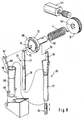
- the lancet device 1 shown in FIG. 1 serves to generate a puncture wound for removing blood for diagnostic purposes.
- Your case 2 has a housing opening 3.
- a puncture wound can be generated by the tip of a lancet which is movable in the housing 2 on a puncture path.
- the housing opening 3 is surrounded by an annular pressure surface 6, with which the lancet device for a puncture against a body part, for example a finger berry, is pressed.
- the skin surface bulges into the housing opening 3.
- the protrusion of the skin facilitates blood leakage, so that already at a comparatively small penetration depth of 0.5 mm to 2 mm a sufficient amount of blood can be removed for diagnostic purposes. By repeatedly pressing against the skin, this effect can be additionally improved ("pumping action").
- a blood drop can also be taken from less well-perfused but also less sensitive to pain, parts of the body.
- the inner diameter of the pressure surface 6 should be quite large, preferably at least 7 mm or even at least 9 mm.
- the pressure surface 6 is inclined inwards towards the housing opening 3.
- a deformable material such as polyurethane or rubber
- the pressure surface is formed there by a component which is referred to as a compression unit because of its pumping action.
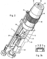
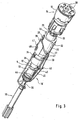
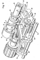
- FIG. 2 shows a lancet device 1 with the housing removed
- FIG. 3 shows its lancet drive assembly 10, which is connected to a drum magazine 16.
- the assembly 10 includes a drive rotor 12 which is driven by a drive spring, and a tensioning rotor 13 for tensioning the drive spring.
- the drive spring which is arranged between the drive rotor 12 and the tensioning rotor 13, not shown in Figures 2 and 3.
- the drive spring 11 can only be seen in FIG. It is a torsion spring which is biased and hinged at one end to the drive rotor 12 and at its other end to the tensioning rotor 13.
- a driven side lancet coupling mechanism 24 by which the rotational movement of the rotatable about an axis drive rotor 12 is converted in a drive phase of the lancet drive into a puncture movement in which the lancet is moved at high speed in the puncture direction to a To create a puncture wound.
- the return movement of the lancet is driven and controlled by the rotational movement of the drive rotor 12 by means of the lancet coupling mechanism 24.
- the lancet drive assembly 10 further comprises a further coupling mechanism 38, with which a rotational movement of a rotating component of the lancet drive in a movement of the reference element 14 or another component of a lancet device can be implemented. Since this further coupling mechanism 38 is used in the described embodiment for moving the reference element 14, it is referred to in this context as a reference element coupling mechanism.
- the reference member is movable relative to the lancet and relative to the housing. It is designed and arranged so that it bears against the skin surface of a patient at the time of puncture of the lancet with its contact surface in a defined position relative to the lancet drive. This ensures that a puncture wound is created with a predetermined puncture depth, which corresponds to the distance between the contact surface of the reference element and the position of the lancet tip extending the most in the puncture direction.
- the reference element 14 includes a drum magazine 16 in which a plurality of lancets can be stored, and a protective cap 17 surrounding the drum magazine 16.
- the contact surface 15 is formed on the protective cap 17, with which the reference element 14 rests against the skin surface.
- a lancet opening 18 is formed, through which the lancet emerges at a puncture in order to produce a puncture wound in a against the housing opening 3 (ie against the pressure surface 6) pressed fingers.
- FIG. 4 shows the reference element 14 with the protective cap 17 removed and its connection to the reference element coupling mechanism 38.
- the drum magazine 16 has a plurality of chambers, in each of which a single lancet is stored. It is also possible, however, to arrange the lancets annularly in a drum magazine 16, which is not divided into individual chambers.
- the number of stored in a drum magazine 16 lancets is largely arbitrary.
- a drum magazine 16 holds three to twelve, more preferably four to eight lancets.
- the drum magazine 16 is rotatable relative to the lancet opening 18 of the protective cap 17 so that outlet openings 20 of the drum magazine 16 can be positioned in sequence for a puncture in alignment with the lancet opening 18.
- the lancet coupling mechanism 24 includes a non-rotatably connected to the housing thrust cylinder 25, from which a coupling rod 26 extends, which is connected during the puncturing and return movement, each with an ("active") lancet.
- the lancet coupling mechanism 24 translates the rotational movement of the drive rotor 12 into a translational movement of the active lancet by means of a cam control.
- the thrust cylinder 25 is provided with a recess in the form of a groove which forms a control cam 27 and by a cam rider 28 of the drive rotor 12 is traversed.
- the cam rider 28 is formed as a control pin which engages in the groove and sits at the end of an outgoing from the drive rotor 12 control arm 29.
- the thrust cylinder 25 is provided with guide elements 32 which engage in axially extending longitudinal grooves in the inner wall of the housing 2 (not shown) to achieve a non-rotatable but in the piercing direction movable connection of the thrust cylinder 25 in the housing 2.
- the guide elements 32 are realized as two guide pins.
- Your control cam 33 is formed by a recess in the form of a groove in the drive rotor 12, in which engages a cam rider 34 in the form of a control pin. It is connected via a coupling arm 35 with a guide rod 36 to which the drum magazine 16 is attached.
- the coupling arm 35 carries the reference member 14.
- the guide rod 36 is rotatable relative to the coupling arm 35 so that the drum magazine 16 in the reference member 14 can be rotated via the guide rod 36, thus using the lancets stored in the drum magazine 16 in turn can be.
- the distance between the drum magazine 16 and the protective cap 17 forming the contact surface 15 is changed by adjusting the length of the reference element 14 by a thread (not shown).
- the setting is made via the in 2 shaft 19 which is connected via a gear 21 with a ring gear 22 of the reference element 14 in engagement.
- the tensioning rotor 13 is set in rotation via a gearbox 37, which is preferably driven by a battery-driven electric motor 40 (FIG. 2).
- the tensioning rotor 13 can also be turned by hand by means of a shaft projecting out of the housing 2.
- the drive rotor 12 and the tensioning rotor 13 first pass through a preparatory rotation angle range in a preparatory phase before the drive spring is tensioned.
- a rotational movement of the clamping rotor 13 via the biased drive spring is transmitted to the drive rotor 12, that during at least part of the preparation phase together (ie simultaneously, but not necessarily, but preferably, synchronously) is rotated with the tensioning rotor 13.
- the movement of the drive rotor 12 in the preparation rotation angle range is converted into a preparatory movement of the coupling rod 26 relative to the drum magazine 16, in which the coupling rod 26 penetrates into a chamber of the drum magazine 16 through an insertion opening (not shown) opposite a lancet opening 18 With locked in a lancet located therein.
- a suitable coupling mechanism are described in WO 02/36010 A1, which is hereby incorporated by reference in the present application.
- the reference member coupling mechanism 38 advances the reference member 14 in the housing 2 toward the housing opening 3 so as to abut the contact surface 15 against the skin of a patient. Due to the size of the inner diameter of the pressure surface 6, the finger berry bulges when creating something in the housing opening 3 of the lancing device 1 (Fig. 1) into it.
- the reference element 14 can therefore abut with its contact surface 15 on the skin, although it is in the housing 2 in a position in which the contact surface 15 extends at a distance behind a plane passing through the inner edge 7 of the pressure surface 6 level.
- the drive rotor 12 When the drive rotor 12 has passed through the preparation rotation angle range, it is locked by means of a blocking element 41, so that during further clamping phase of the lancet drive movement upon further rotation of the drive rotor 13, the drive spring is tensioned.
- the blocking element 41 is formed as a resiliently applied to an inner wall of the housing 2 release tab, which starts from the drive rotor 12 and engages for locking the drive rotor 12 in a recess in the inner wall of the housing.
- the release tongue is made in one piece with the control arm 42 and the control pin 28 as an injection molded part.
- a puncturing movement is initiated after completion of the clamping process in that the blocking element 41 is released from its blocking engagement, so that rotates in the drive phase of the drive rotor 12, driven by the drive spring, very quickly in its rest position. It rotates in the same direction of rotation as the tensioning rotor 13 when tensioning the drive spring.
- This rapid movement of the drive rotor 12 is converted via the lancet coupling mechanism 24 into a puncture and return movement of the lancet and via the reference element coupling mechanism 38 in a return movement of the reference element 14.
- the puncturing process can be triggered (triggered), for example, by pressing the contact surface 15 of the reference element 14 against the skin with a predetermined minimum force.
- the reference element 14 preferably has a pressure sensor with which a signal required for triggering a puncturing movement can be generated as soon as pressure is exerted on the contact surface 15 which exceeds a predetermined minimum contact pressure.
- the pressure sensor can for example be realized in that the contact surface 15 is mounted on a spring and an electrical contact is closed only after compression of the spring.
- a release button 5 can be arranged on the housing 2 of the lancet device 1 (FIG. 1).
- an electrical signal is initially generated in the illustrated embodiment, by which the electric motor 40 is set in motion.
- the tensioning rotor 13 is rotated by a small rotational angle step.
- the tensioning rotor 13 has a release cam 44 which, upon rotation of the tensioning rotor 13, actuates a release mechanism 45 beyond a predetermined angular position by which the previously existing escapement of the drive rotor 12 is released.
- the release mechanism 45 is formed as a rocker which is pivotally mounted about bearing pin 46 on the housing 2.
- the blocking element 41 has a shoulder with a return surface 48.
- the head part 47 is located above the blocking element 41 and presses on the return surface 48 of the release tongue 41, whereby it is released from its engagement with the recess of the housing 3.
- the drive spring relaxes, so that the drive phase of the movement of the lancet drive expires.
- FIG. 5 illustrates the movements of the lancet and the reference element 14, which are driven and controlled by the rotational movement of the drive rotor 12 by means of the coupling mechanisms 24, 38.
- the stroke, that is to say the movement in the axial direction, of the coupling rod 26 is plotted as curve A and the stroke of the reference element 14 as curve B over the rotational angle position of the drive rotor 12.
- a work cycle begins with the beginning of a rotary movement of the tensioning rotor and ends with the end of the return movement of the lancet after the puncture.
- the drive rotor 12 (as set forth above in a relatively slow movement simultaneously with the tensioning rotor) undergoes a preparation rotation angle range ⁇ . It ends at about 120 ° (indicated in Figure 5 by a vertical line).
- the movement of the drive rotor 12 in the preparation rotation angle range is converted by means of the two coupling mechanisms 24, 38 so that both the coupling rod 26 and the reference element 14 in the device are moved forward (towards the housing opening 3) until the contact surface 15 of the reference element 14 bears against the skin and the coupling rod 26 is coupled to a lancet.
- the drive rotational angle range (which corresponds to the drive phase of the lancet drive movement, consisting of puncture and return movement) following the preparation rotational angle range is traversed in less than 100 ms, preferably less than 20 ms.
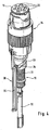
- FIG. 6 shows a further embodiment of a lancet drive assembly 10. It is shown without the reference element 14, so that the head 50 of the guide rod 36, on which the drum magazine 16 is slipped, and the coupling rod 26, which latches for a puncture with a lancet , are easier to recognize. It can also be seen that the coupling rod head 49 has a thickening, which allows a positive coupling to a lancet. As with the embodiment described with reference to Figures 2 and 3, the arranged between the drive rotor 12 and the tensioning rotor 13 drive spring is not shown.
- the drive rotor 12 and the clamping rotor 13 have stop members 51 which abut each other in a stop position of the rotors 12, 13 and thereby to stop a rotational movement of the drive rotor 12 relative to the tensioning rotor 13.
- stop members 51 are also present in the embodiment described above. They serve in particular to receive the bias of the drive spring and stop the drive rotor 12 at the end of the puncture and return movement.
- a rotational movement of the tensioning rotor 13 is transmitted to the drive rotor 12 via the drive spring 11, so that the tensioning rotor 13 and the drive rotor 12 rotate together in this rotation angle range.
- the bias of the drive spring 11 a close coupling of the clamping rotor 13 is achieved with the drive rotor 12, so that the rotational angular position of the clamping rotor 13 during the common rotation of the rotational angular position of the drive rotor at most by 10 °, preferably at most by 5 °, deviates.
- a sufficiently high bias of the drive spring 11 is used in this way to achieve a largely synchronous, so angular and speed-sensitive movement of the two rotors. This has the advantage that the movements of the coupling mechanisms 24, 38 can be controlled even more precisely.
- synchronous movement of the two rotors 12, 13 may also be achieved by coupling them together while passing through the preparation rotational angle range by a locking bar (not shown).
- this embodiment corresponds largely to the embodiment described with reference to FIGS 2 to 4.
- the reference element coupling mechanism 38 is not used in this design for a quick return movement of the reference element 14 after a puncture, but for a precise setting of the penetration depth by a slow movement of the reference element 14. As FIG.
- the penetration depth depends on the position in which the contact surface 15 of the reference element 14 is relative to the coupling rod 26 when the puncturing movement takes place.
- the reference element 14 is displaced in the axial direction relative to the coupling rod 26 prior to a puncture. This adjustment movement takes place independently of the puncturing movement and can be carried out slowly.
- the set position should not change during the puncturing movement. Therefore, the reference member coupling mechanism 38 is preferably coupled to the tensioning rotor 13, which rotates relatively slowly.
- FIG. 7 shows the movement of the coupling rod 26 and thus also of the lancet as a curve C, as well as the movement of the reference element 14 as a curve D as a function of the angular position of the clamping rotor 13.
- a first portion of the control cam 33 of the reference element coupling mechanism is used to first move the reference element 14 in a maximum position M, which corresponds to a minimum penetration depth. If the tensioning rotor 13 is then further rotated, the reference element 14 is moved back from this maximum position M to a position which corresponds to the desired penetration depth ("puncturing position"). The farther the reference member 14 is retracted relative to the coupling bar 26, the greater the depth of the subsequent puncture. If the puncture position is reached with the desired penetration depth, the electric motor 40 is switched off and the tensioning rotor 13 in this Position locked. After triggering the tensioning rotor 13 terminates its duty cycle by being further rotated in the movement section Q until it reaches its starting position.
- the electric motor 40 drives the tensioning rotor 13 via a two-stage worm gear 37, so that the rotational angular position of the tensioning rotor 13 can be precisely adjusted by electronically counting the revolutions of one or more parts of the worm gear 37.
- FIGS. 2-4 and 6 may be combined so that a first reference element coupling mechanism couples the reference element 14 to the tensioning rotor 13 to adjust the penetration depth prior to initiation of a puncturing motion, and a second reference element coupling mechanism couples the reference element 14 to the tensioning element 13 Drive rotor 12 coupled to move after a puncture, the reference element 14.
- the drive spring is used for a fast return movement, which would be very difficult to realize by an electric motor 40, while the electric motor 40 is used for a slow adjustment movement of the penetration depth, for which the drive spring is less suitable.
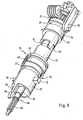
- Figures 8 and 9 show a further embodiment of a lancet drive assembly 10.
- the reference element 14 is formed as a sample receiving unit 60 in this embodiment.
- the sample receiving unit 60 includes a guide channel 61 for the lancet 4 and a sample receiving channel 63 having a mouth 63a for receiving a sample.
- the sample receiving unit 60 further includes a reaction zone 64 with reagents to which the sample can be delivered through the sample receiving channel 63.
- the lancet drive assembly 10 includes a drive rotor 12 driven by a drive spring 11 which is rotatable about an axis 59 and a tensioning rotor 13 for tensioning the drive spring 11.
- Drive rotor 12 and tension rotor 13 are coaxially arranged.
- the drive spring 11 is designed as a helical spring leg spring. Alternatively, for example, a coil spring as a drive spring 11 is possible.
- the turns of the drive spring 11 may be spaced to minimize frictional losses, or close to each other to damp torsional vibrations, with tension biasing providing damping friction between the turns.
- the clamping rotor 13 has a stop member in the form of a stopper groove 52 into which a stop pin 53 of the drive rotor 12 engages.
- the stop pin 53 is pressed by the bias of the drive spring 11 against one end of the circular stop 27, to which he strikes in a rest position.
- the reference element coupling mechanism 38 comprises a pivotally suspended about two bearing pin 69 sleeve 65 with a rigid control arm 66 which engages with a control pin as a cam ridge 67 in a formed by a groove-shaped cam 68 of the drive rotor 12.
- the cam 68 has two semi-circular sections with different radii.
- the coupling rod 70 of the lancet coupling mechanism 24 is translationally movable to allow the puncture and return movement of the lancet 4 in the sleeve 65 moves the cam rider 67 between these two sections.
- the coupling rod 70 is driven by the drive rotor 12 via a connecting rod 71.
- the connecting rod 71 carries a crank pin 72 which engages in a bore 75 of the drive rotor 12.
- a second reference element coupling mechanism 39 is provided in the illustrated embodiment, which withdraws the sample receiving unit 60 slightly after the puncturing motion and pushes it forward again after the pivoting movement, a drop of blood can be picked up from the sample receiving channel 63.
- the second reference element coupling mechanism 39 comprises a sleeve 77, from which a rigid control arm 78 with a control pin as cam cam 79 emanates, which engages in a formed by a groove-shaped cam 73 of the drive rotor 12.
- the control cam 68 is arranged on a first side (front side) of the drive rotor 12 and the control cam 73 on its rear side.
- the sleeve 77 is disposed around the coupling rod 70 and in the sleeve 65 of the first reference member coupling mechanism 38.
- the lancet device is attached to a body part of a patient, so that the contact surface 15 of the reference element 14 formed by the sample receiving unit 16 rests against the skin surface.
- the tensioning rotor 13 is rotated by 180 °, while the drive rotor 12 is held by a locking element (not shown).
- the locking element (not shown) is released, so that the drive rotor 12 a snap movement of 180 ° performs until the stop pin 53 abuts against the end of the stop groove 52 of the clamping rotor 53.
- the crank pin 72 describes the lower half of a circular path, so that by means of the connecting rod 71 and the coupling rod 70 of the lancet coupling mechanism 24, the piercing movement of the lancet 4 is performed.
- the second reference member coupling mechanism 39 through the cam 73, causes the sleeve 77 and the sample receiving unit 60 held therein to be withdrawn. Since the contact surface 15 no longer rests on the skin surface, sample liquid can escape.
- the tensioning rotor 13 is again moved by 180 °, wherein the drive rotor 12 follows because of the bias of the drive spring 11 of this 180 ° movement.
- Due to the shape of the cam 68 there is a pivoting movement of the sleeve 65, which is dimensioned so that the mouth 63a ( Figure 10) of the sample receiving unit 60 is aligned with the puncture site.
- the groove 73 causes the sample receiving unit 60 to be pushed forward again via the connecting rod 71 and the coupling rod 70, so that the mouth 63a comes into contact with escaped blood and absorbs it.
- a third groove in the drive rotor can be used to drive the coupling rod 70 via a third cam rider.
- To improve blood leakage may additionally with a pressure piece, for example, the lower edge of the sleeve 77, on the skin surface in the vicinity of the puncture site be acted.
- a pressure piece for example, the lower edge of the sleeve 77
- blood can be squeezed out of the puncture wound, which can be absorbed by the sample receiving unit 60. If the contact force is lowered after blood collection has been completed, then the puncture wound closes.
- the sample receiving unit 60 is additionally provided with a pump plunger 76 (Fig. 10) for enhancing capillary forces of the sample receiving channel 63 by suction forces.
- the sample receiving unit 60 is provided with struts 80 which relax after puncturing and retract the pump plunger 76 so that blood is drawn into the sample receiving channel 63.
- a pumping movement can be realized to support the blood collection, for example by clamping rotor 13 and drive rotor 12 are moved forward and backward over a small angular range. If the bias of the drive spring 11 is so great that the tensioning rotor 12 and the drive rotor 13 move substantially synchronously, in particular their rotational position deviates from each other by at most 10 °, in addition to forward movements and backward movements in precise control of the movements are possible.
- FIG. 11 shows a perspective view of a partial view of a further embodiment of a lancet drive assembly 10 with a drive rotor 12 and a tensioning rotor 13.
- the drive spring is not shown in FIG.
- the peculiarity of the illustrated assembly 10 consists in a lancet coupling mechanism 24 having a lever 81 on which the cam rider 28 is arranged for traversing the cam 27 formed as a groove of the drive rotor 12.
- the lever 81 is rotatably mounted in a pivot point 82, so that the scoring on a flank of the control cam 27 with the lancet holder 83 stroke is increased by a lever ratio.
- the sections 84,85 of the lever 81 on both sides of the pivot point 82 each form a lever arm, so that the stroke increase achieved calculated from the ratio of the lengths of the two lever arms 84,85. These lengths are to be measured outwards from the fulcrum 82, i. E. to the cam rider 28 and the attachment point 86 of the lancet holder 83, which is moved by the lever 81.
- a large stroke can be achieved with the lever ratio described, thus realizing a smaller and more compact hand-held device.
- a large stroke can be achieved only by a relatively large diameter of the corresponding cam 27, otherwise it comes to a self-locking. Namely, the pitch angle of a control cam 27 exceeds a critical value, which depends on the friction coefficient, the cam cam 28 blocks and can not be set in motion by an arbitrarily large torque. With the described leverage can be achieved even with less steeply rising flanks of a cam 27, a large stroke.
- the leverage is part of the lancet coupling mechanism 24, so that by adjusting the pivot point 82, the stitch depth can be adjusted.
- the advantages of the leverage can also be used for another coupling mechanism that is coupled to the drive rotor or the tensioning rotor.
- the pivot point 82 is formed as a pin on a sliding base 87.
- the base 87 can be moved by means of a threaded spindle 88 for adjusting the piercing depth.
- the threaded spindle 88 can be used to adjust the position of the pivot point 82, for example, an eccentric or a wedge.
- the tensioning rotor 13 is passed through the drive rotor 12.
- the tensioning rotor 13 carries a control cam 33, which is traversed by a cam follower 34 of the reference element coupling mechanism 38. If the tensioning rotor 13 is rotated to tension the drive spring, not shown, a reference element carrier 91 is advanced by the reference element coupling mechanism 38.
- the reference element carrier 91 has a latching mechanism 90 in the form of a latching hook, which engages with the housing, not shown. In this way, the reference element is fixed for a puncture with respect to the lancet drive 9 and with respect to the housing, not shown.
- the associated release mechanism may be formed in accordance with the embodiment explained with reference to Figures 1 to 5 and is therefore not shown in Figure 11 for simplicity.
- the tensioning rotor 13 carries a further release cam 93, with which by a suitable mechanism (not shown) of the locking mechanism 90 forming latching hook is released from its latching, so that the reference element support 91 and thus also the reference element can be withdrawn after a puncture.
Abstract
Description
Die Erfindung betrifft eine Lanzettenvorrichtung zum Erzeugen einer Einstichwunde, insbesondere zum Entnehmen einer Körperflüssigkeit für Diagnosezwecke, und eine Lanzettenantriebs-Baugruppe für eine Lanzettenvorrichtung.The invention relates to a lancet device for producing a puncture wound, in particular for removing a body fluid for diagnostic purposes, and a lancet drive assembly for a lancet device.
Um für analytisch-diagnostische Zwecke eine geringe Menge Körperflüssigkeit (Blut und/oder interstitielle Flüssigkeit) aus einem Körperteil (meist aus einem Finger oder Ohrläppchen) zu entnehmen, werden Lanzetten verwendet, die zur Erzeugung einer Einstichwunde in das entsprechende Körperteil gestochen werden. Soweit dies manuell geschieht, ist speziell trainiertes Personal erforderlich. Dennoch ist der Einstich mit erheblichem Schmerz verbunden.In order to remove for analytical diagnostic purposes a small amount of body fluid (blood and / or interstitial fluid) from a body part (usually from a finger or earlobe), lancets are used, which are stung to create a puncture wound in the corresponding body part. As far as this is done manually, specially trained personnel is required. Nevertheless, the puncture is associated with considerable pain.
Bereits seit Langem werden Blutentnahmesysteme verwendet, die aus einer Lanzettenvorrichtung und zugehörigen, für die jeweilige Lanzettenvorrichtung speziell angepaßten Lanzetten bestehen. In einem Gehäuse der Lanzettenvorrichtung befindet sich ein Lanzettenantrieb, durch den eine Lanzette mechanisch in die Haut gestochen wird. Als Antriebselement für die Einstichbewegung dient eine Feder. Zu Beginn der Entwicklung waren sehr einfache Konstruktionen gebräuchlich, bei denen die Lanzette unmittelbar an einem Ende einer in einem länglichen Gehäuse angeordneten Druckfeder befestigt war (z.B. US-Patent 4,469,110).Blood collection systems have long been used which consist of a lancet device and associated lancets specially adapted to the particular lancet device. In a housing of the lancet device is a lancet drive, through which a lancet is mechanically pricked into the skin. When Drive element for the puncturing movement is a spring. At the beginning of the development, very simple constructions were used, in which the lancet was attached directly to one end of a compression spring arranged in an elongated housing (eg US Pat. No. 4,469,110).
Derartige Blutentnahmesysteme wurden jedoch den hohen Anforderungen nicht gerecht, die zu erfüllen sind, wenn eine regelmäßige Überwachung analytischer Werte des Blutes erforderlich ist. Dies gilt insbesondere für Diabetiker, die ihren Blutzuckerspiegel häufig kontrollieren sollten, um ihn durch Insulininjektionen innerhalb bestimmter Sollgrenzen halten zu können. Durch umfangreiche wissenschaftliche Untersuchungen wurde bewiesen, daß mittels einer Intensivtherapie mit mindestens vier Blutanalysen pro Tag eine dramatische Reduzierung schwerster Spätschäden des Diabetis Mellitus (beispielsweise eine Retinopathie mit resultierender Erblindung des Patienten) erreicht werden kann.However, such blood collection systems have failed to meet the high requirements that must be met when periodic monitoring of analytical blood levels is required. This is especially true for diabetics, who should often control their blood sugar levels to keep them within certain limits by insulin injections. Extensive scientific research has shown that intensive therapy with at least four blood analyzes a day can dramatically reduce severe late damage to diabetic mellitus (such as retinopathy resulting in blindness to the patient).
Diese Intensivtherapie setzt voraus, daß die Blutentnahme mit einem möglichst geringen Schmerz verbunden ist. Mit dem Ziel, diesbezüglich eine Verbesserung zu erreichen, wurden zahlreiche unterschiedliche Blutentnahmesysteme entwickelt.This intensive therapy requires that the blood collection is associated with the least possible pain. With the aim of achieving an improvement in this regard, numerous different blood collection systems have been developed.
Eine schmerzarme Blutentnahme ermöglichen Lanzettenvorrichtungen, deren Lanzettenantrieb einen Antriebsrotor einschließt, auf den einerseits (antriebsseitig) die Antriebsfeder derartig wirkt, daß er von dieser in eine Drehbewegung um eine Rotationsachse versetzt werden kann, und der andererseits über einen (abtriebsseitigen) Kopplungsmechanismus derartig mit der Lanzette gekoppelt ist, daß die aus der Entspannungsbewegung der Antriebsfeder resultierende Rotation des Antriebsrotors in eine Einstichbewegung umgesetzt wird. Die vorliegende Erfindung bezieht sich auf eine Lanzettenvorrichtung mit einem solchen Rotor-Lanzettenantrieb, der in verschiedenen Ausführungsformen bekannt ist.A low-pain blood sampling allow lancet devices whose lancet drive includes a drive rotor, on the one hand (drive side), the drive spring acts such that it can be offset by this in a rotational movement about an axis of rotation, and on the other hand via a (output side) coupling mechanism soig with the lancet coupled, that from the relaxation movement of the drive spring resulting rotation of the drive rotor is converted into a puncturing movement. The present invention relates to a lancing device with such a rotor-lancet drive, which is known in various embodiments.
Der abtriebsseitige Kopplungsmechanismus ist in der Regel so konstruiert, daß die Lanzette während der gesamten Einstich- und Rückführbewegung (Antriebsphase der Bewegung des Lanzettenantriebs) mit dem Antriebsrotor gekoppelt ist und dadurch die Lanzettenbewegung vollständig durch die entsprechende Bewegung des Antriebsrotors kontrolliert wird. Ein frühes Beispiel einer derartigen Konstruktion zeigt das US-Patent 4924879. Modernere Ausführungsformen sind beispielsweise in den US-Patenten 6409740 und 6419661 beschrieben.The output-side coupling mechanism is typically designed so that the lancet is coupled to the drive rotor during the entire insertion and return movement (drive phase of the movement of the lancet drive) and thereby the lancet movement is completely controlled by the corresponding movement of the drive rotor. An early example of such a construction is shown in U.S. Patent 4,924,879. More modern embodiments are described, for example, in U.S. Patents 4,007,097,440 and 4,619,661.
Das Spannen der bekannten Rotor-Lanzettenantriebe erfolgt in der Regel dadurch, daß der Rotor mittels eines geeigneten "antriebsseitigen Kopplungsmechanismus" gegen die Kraft der Antriebsfeder zurückgedreht wird. In neuerer Zeit ist eine Konstruktion bekannt geworden, bei der zum Spannen der Antriebsfeder ein Spannrotor verwendet wird. Dadurch läßt sich erreichen, daß das Spannen des Lanzettenantriebs in einer Spannphase seiner Bewegung durch eine Drehung des Spannrotors erfolgt, die mit der Drehung des Antriebsrotors in der Antriebsphase gleichgerichtet ist. Dieses Antriebsprinzip wird auch als OWADAC (one way alternating drive and cocking) bezeichnet. Ein solcher Rotorantrieb ist beispielsweise in der EP 1384438 A1 beschrieben.The clamping of the known rotor lancet drives is usually carried out in that the rotor is rotated back by means of a suitable "drive-side coupling mechanism" against the force of the drive spring. Recently, a construction has become known in which a tensioning rotor is used for tensioning the drive spring. As a result, it can be achieved that the clamping of the lancet drive in a clamping phase of its movement takes place by a rotation of the clamping rotor, which is rectified with the rotation of the drive rotor in the drive phase. This drive principle is also referred to as OWADAC (one way alternating drive and cocking). Such a rotor drive is described for example in EP 1384438 A1.
Trotz umfangreicher Entwicklungsarbeiten besteht weiter ein großes Interesse an einer Lanzettenvorrichtung, welche die schwierigen und teilweise gegenläufigen Anforderungen (minimales Schmerzempfinden, einfache Bedienbarkeit, kompakte Bauweise, kostengünstige Konstruktion) gleichzeitig möglichst weitgehend erfüllt. Als weitere Anforderung tritt hinzu, daß die Lanzettenvorrichtung beim Gebrauch nicht oder möglichst wenig durch austretendes Blut verschmutzt wird. Aufgabe der Erfindung ist es, diese Anforderungen möglichst weitgehend zu erfüllen.Despite extensive development work, there continues to be great interest in a lancet device that meets the difficult and sometimes contradictory requirements (minimal pain sensation, ease of use, compact design, cost-effective design) simultaneously fulfilled as much as possible. Another requirement is that the lancet device during use is not or as little as possible contaminated by escaping blood. The object of the invention is to fulfill these requirements as far as possible.
Diese Aufgabe wird gelöst durch eine Lanzettenvorrichtung zum Erzeugen einer Einstichwunde in einer Hautoberfläche, insbesondere zum Entnehmen einer Körperflüssigkeit für Diagnosezwecke, umfassend ein Gehäuse, in dem eine Lanzette auf einem Einstichweg beweglich ist, einen Lanzettenantrieb mit einem durch eine Antriebsfeder antreibbaren Antriebsrotor, einen Lanzetten-Kopplungsmechanismus, durch den während eines Arbeitszyklus des Lanzettenantriebs eine Drehbewegung des Antriebsrotors in eine Einstich- und Rückführbewegung der Lanzette umgesetzt wird, ein relativ zu der Lanzette und relativ zu dem Gehäuse bewegliches Referenzelement, das sich zum Zeitpunkt des Einstichs in einer definierten Position relativ zu dem Lanzettenantrieb (und damit zu dem Einstichweg) befindet und mit einer Kontaktfläche an der Hautoberfläche anliegt, so daß durch die Einstichbewegung eine Einstichwunde mit reproduzierbarer Einstichtiefe erzeugt wird, und einen Referenzelement-Kopplungsmechanismus, der zum Bewegen des Referenzelementes mit dem Lanzettenantrieb gekoppelt ist.This object is achieved by a lancet device for generating a puncture wound in a skin surface, in particular for removing a body fluid for diagnostic purposes, comprising a housing in which a lancet is movable on a puncture path, a lancet drive with a drive rotor drivable by a drive spring, a lancet Coupling mechanism by which, during a cycle of operation of the lancet drive, a rotational movement of the drive rotor is converted into a puncture and return movement of the lancet, a relative to the lancet and relative to the housing movable reference element, which at the time of puncture in a defined position relative to the Lancet drive (and thus to the puncture) is located and rests with a contact surface on the skin surface, so that a puncture wound with reproducible puncture depth is generated by the puncturing movement, and a reference element coupling mechanism which is coupled to move the reference element with the lancet drive.
Um für Diagnosezwecke mit einem möglichst schmerzarmen Einstich eine ausreichende Menge Blut zu gewinnen, ist die optimale Einstichtiefe von zentraler Bedeutung. Variationen von 0,05 mm können eine signifikante Änderung des Schmerzempfindens und/oder der bei einem Einstich gewonnenen Menge Blut zur Folge haben.In order to obtain sufficient blood for diagnostic purposes with the least painful puncture possible, the optimal penetration depth is of central importance. Variations of 0.05 mm may result in a significant change in the sensation of pain and / or the amount of blood collected during a puncture.
Bei Lanzettenvorrichtungen mit Rotor-Lanzettenantrieb wird die Bewegung der Lanzette, wie beschrieben, durch die Kopplung mit dem Antriebsrotor präzise kontrolliert. Die Einstichtiefe entspricht dabei dem Abstand zwischen dem tiefsten Punkt (Umkehrpunkt) der Lanzettenbewegung und der Ebene einer Hautkontaktfläche, die bei bekannten Konstruktionen als ringförmige Andruckfläche eine Öffnung am vorderen Ende des Gehäuses umgibt. Die Andruckfläche wird gegen das Körperteil gedrückt, aus dem Blut entnommen werden soll. Zur Einstellung der Einstichtiefe ist ihre Axialposition (d.h. die Position in Einstichrichtung) verstellbar.In lancet devices with a rotor-lancet drive, the movement of the lancet, as described, is precisely controlled by the coupling with the drive rotor. The puncture depth corresponds to the distance between the lowest point (reversal point) of the lancet movement and the level of a skin contact surface, which surrounds an opening at the front end of the housing in known constructions as an annular pressure surface. The pressure surface is pressed against the body part from which blood is to be taken. To adjust the penetration depth, its axial position (i.e., the position in the puncture direction) is adjustable.
Ist die von der Andruckfläche umgebene Öffnung nur wenig größer als der Lanzettendurchmesser, so ist zwar die Einstichtiefe gut reproduzierbar, jedoch ist die durch einen Einstich gewonnene Blutmenge relativ gering und insbesondere für integrierte Systeme, bei denen eine Blutprobe in der Lanzettenvorrichtung ausgewertet werden soll, nicht ausreichend. Ist die von der Andruckfläche umgebene Gehäuseöffnung größer, so daß sich die Haut in sie hineinwölbt, läßt sich wegen einer erhöhten Durchblutung mit einem Einstich eine größere Menge Blut gewinnen.If the opening surrounded by the pressure surface is only slightly larger than the lancet diameter, the penetration depth is well reproducible, but the amount of blood obtained by a puncture is relatively small and, in particular, for integrated systems in which a blood sample is to be evaluated in the lancet device sufficient. If the housing opening surrounded by the pressure surface is larger, so that the skin bulges into it, a larger amount of blood can be obtained because of an increased blood flow with a puncture.
Im Rahmen der Erfindung wurde festgestellt, daß mit einer stationären Andruckfläche am vorderen Ende des Gehäuses vielfach keine optimale Reproduzierbarkeit der Einstichtiefe zu erreichen ist, insbesondere wenn sich die Haut beim Anpressen einer Lanzettenvorrichtung in die von der Andruckfläche umgebene Gehäuseöffnung hineinwölbt. Deren Innenrand stellt dann nur eine ungenaue Referenz für die Einstichtiefe dar. Bei kleineren Gehäuseöffnungen ist dieser Effekt weniger stark ausgeprägt, jedoch wird dann weniger Blut gewonnen, und es besteht ein erhöhtes Risiko, daß die Lanzettenvorrichtung durch aus der Einstichwunde austretendes Blut verschmutzt wird.In the context of the invention it has been found that with a stationary pressure surface at the front end of the housing often no optimal reproducibility of the penetration depth can be achieved, especially when the skin bulges when pressing a lancet device in the surrounded by the pressure surface housing opening. Its inner edge is then only an inaccurate reference for the penetration depth. With smaller housing openings, this effect is less pronounced, but then less blood is gained, and there is an increased risk that the lancet device is contaminated by blood emerging from the puncture wound.
Bisher wurde versucht, zur Lösung dieses Problems einen möglichst optimalen Kompromiß für den Innendurchmesser der Andruckfläche, d.h. die Größe der Gehäuseöffnung, zu finden. Abweichend von dieser üblichen Vorgehensweise weist eine erfindungsgemäße Lanzettenvorrichturig ein (relativ zu der Lanzette und dem Gehäuse) bewegliches Referenzelement auf, das während des Einstichs mit einer Kontaktfläche an der Haut eines Patienten anliegt. Zur Bewegung des Referenzelementes dient ein Referenzelement-Kopplungsmechanismus, der zusätzlich zu dem Lanzetten-Kopplungsmechanismus vorhanden ist. Das bewegliche Referenzelement befindet sich während des Einstichs, zumindest zum Zeitpunkt des maximalen Eindringens der Lanzettenspitze in die Haut, in einer definierten Position relativ zu dem Lanzettenantrieb. Anhand der nachfolgenden Beschreibung wird deutlich, daß mit einer solchen Konstruktion eine sehr gute Reproduzierbarkeit der Tiefe der Einstichwunde trotz Wölbung der Haut erzielt werden kann.So far, an attempt was made to solve this problem as optimal as possible compromise for the inner diameter of the pressure surface, i. the size of the housing opening, to find. In contrast to this conventional procedure, a lancet device according to the invention has a reference element (movable relative to the lancet and the housing), which bears against the skin of a patient during the puncture with a contact surface. To move the reference element is a reference element coupling mechanism, which is provided in addition to the lancet coupling mechanism. The movable reference element is located during the puncture, at least at the time of maximum penetration of the lancet tip into the skin, in a defined position relative to the lancet drive. It is clear from the following description that with such a construction a very good reproducibility of the depth of the puncture wound despite vaulting of the skin can be achieved.
Das Referenzelement einer erfindungsgemäßen Lanzettenvorrichtung kann als Probenaufnahmeeinheit ausgebildet sein, die nebeneinander eine Führung für die Lanzette und einen Probenaufnahmekanal zum Aufnehmen einer Blutprobe aufweist. Von der Probenaufnahmeeinheit kann die Blutprobe zu einer weiteren Bearbeitungsstation (beispielsweise um sie zu analysieren) weitergeleitet werden. Bevorzugt ist jedoch eine Reaktionszone mit Reagenzien integraler Bestandteil der Probeaufnahmeeinheit, so daß die Probeaufnahmeeinheit ein vollständiges Analyseelement bildet. Die Reaktion der Probe mit den Reagenzien in der Reaktionszone führt zu einer Änderung eines physikalischen Zustandes (beispielsweise zu einer Farbänderung oder bei elektrochemischen Analyseelementen zur Änderung eines Stromflusses) die als Grundlage für die Ermittlungen der Konzentration eines in der Probe enthaltenen Analyten verwendet werden kann. Da solche Analyseelemente bekannt sind, ist eine nähere Erläuterung der Testprinzipien nicht erforderlich. Die Analyseelemente (oder sonstige Probeaufnahmeeinheiten) werden nach einmaliger Verwendung entsorgt. Deshalb spielt eine Verschmutzung durch aus der Einstichwunde austretendes Blut keine Rolle.The reference element of a lancet device according to the invention may be designed as a sample receiving unit, which has a guide for the lancet side by side and a sample receiving channel for receiving a blood sample. From the sample receiving unit, the blood sample can be forwarded to another processing station (for example, to analyze it). Preferably, however, a reaction zone with reagents is an integral part of the sample receiving unit, so that the sample receiving unit forms a complete analysis element. The reaction of the sample with the reagents in the reaction zone leads to a change in a physical state (for example to a color change or at electrochemical analysis elements to change a current flow) that can be used as a basis for the determination of the concentration of an analyte contained in the sample. Since such analysis elements are known, a more detailed explanation of the test principles is not required. The analysis elements (or other sample receiving units) are disposed of after a single use. Therefore, contamination by blood leaving the puncture wound plays no role.
Da die Mündung des Probenaufnahmekanals, durch die die Probenaufnahme erfolgt, räumlich getrennt von der Mündung des Führungskanals ist, muß nach dem Einstich die Probenaufnahmeeinheit so bewegt werden, daß die Mündung des Probenaufnahmekanals für eine Probenaufnahme zu der Einstichwunde gebracht wird. Dazu dient der Referenzelement-Kopplungsmechanismus, der zusätzlich zu dem Lanzetten-Kopplungsmechanismus vorhanden ist. Zwar ist es prinzipiell auch möglich, die Mündung des Lanzetten-Führungskanals auch für den Probenaufnahmekanal zu nutzen, so daß die Kanäle nicht räumlich getrennt sind und die erläuterte Bewegung nicht notwendig ist. Im Rahmen der Erfindung wurde jedoch festgestellt, daß es günstiger ist, getrennte Kanäle vorzusehen und, beispielsweise durch eine Schwenkbewegung, die Mündung des Probenaufnahmekanals nach dem Einstich zu der Einstichwunde zu bringen.Since the mouth of the sample receiving channel, through which the sample receiving takes place, is spatially separate from the mouth of the guide channel, after the puncture, the sample receiving unit must be moved so that the mouth of the sample collection channel is brought to the puncture wound for a sample receiving. This is done by the reference element coupling mechanism, which is provided in addition to the lancet coupling mechanism. Although it is in principle also possible to use the mouth of the lancet guide channel for the sample receiving channel, so that the channels are not spatially separated and the described movement is not necessary. In the invention, however, it has been found that it is more convenient to provide separate channels and, for example, by a pivoting movement, to bring the mouth of the sample receiving channel after the puncture to the puncture wound.
Ein alternatives Ausführungsbeispiel betrifft Fälle, bei denen das Referenzelement ein mehrfach verwendbares Bauteil der Lanzettenvorrichtung ist. In diesem Fall ist eine Verschmutzung des Referenzelementes durch aus der Einstichwunde austretendes Blut selbstverständlich unerwünscht. Es wird deshalb gemäß einer bevorzugten Ausgestaltung der Erfindung nach dem Einstich rasch von der Einstichwunde wegbewegt, bevor es durch austretendes Blut verschmutzt wird.An alternative embodiment relates to cases in which the reference element is a reusable component of the lancing device. In this case, contamination of the reference element by exiting from the puncture wound blood is of course undesirable. It is therefore according to a preferred embodiment of the invention after the puncture quickly from the Puncture wound away before it is contaminated by escaping blood.
Im Rahmen der Erfindung wurde festgestellt, daß der Anpreßdruck, mit dem das Referenzelement bei einem Einstich gegen die Haut gepreßt wird, dem Austreten von Blut aus der Einstichwunde entgegengewirkt. Diese Erkenntnis wird genutzt, indem das Referenzelement durch eine ausreichend schnelle Bewegung von der Einstichwunde entfernt wird, bevor Blut austreten und das Referenzelement (in störendem Ausmaß) verschmutzen kann.In the context of the invention it has been found that the contact pressure with which the reference element is pressed against the skin during a puncture counteracts the escape of blood from the puncture wound. This finding is exploited by removing the reference element from the puncture wound by a sufficiently rapid motion before blood can leak out and contaminate the reference element (to an annoying degree).
Bevorzugt wird das Referenzelement innerhalb von 50 Millisekunden nach dem Einstich mindestens 2 mm von der Einstichwunde wegbewegt. Zum Antreiben einer derartig schnellen Rückführbewegung des Referenzelementes eignet sich insbesondere der Antriebsrotor des Lanzettenantriebs. Für einen möglichst schmerzfreien Einstich muß auch die Lanzette mit hoher Geschwindigkeit bewegt werden. Bevorzugt setzt der Referenzelement-Kopplungsmechanismus deshalb eine Drehbewegung des Antriebsrotors in eine Bewegung des Referenzelementes um, die vorzugsweise translatorisch verläuft.Preferably, the reference element is moved away within 50 milliseconds after the puncture at least 2 mm from the puncture wound. To drive such a fast return movement of the reference element, in particular, the drive rotor of the lancet drive is suitable. For a painless puncture as possible, the lancet must be moved at high speed. The reference element coupling mechanism therefore preferably converts a rotary movement of the drive rotor into a movement of the reference element, which preferably extends in a translatory manner.
Ein wichtiger Bestandteil der erfindungsgemäßen Lanzettenvorrichtung, der jedoch auch selbständige Bedeutung hat, ist eine Lanzettenantriebs-Baugruppe umfassend einen Lanzettenantrieb mit einem durch eine Antriebsfeder antreibbaren Antriebsrotor und einem Spannrotor zum Spannen der Antriebsfeder, einem ersten Lanzetten-Kopplungsmechanismus zum Umsetzen einer Drehbewegung des Antriebsrotors in eine Einstich- und Rückführbewegung der Lanzette und einen weiteren mit dem Lanzettenantrieb gekoppelten Kopplungsmechanismus.An important component of the lancing device according to the invention, which however also has independent significance, is a lancet drive assembly comprising a drive rotor driven by a drive spring and a tensioning rotor for tensioning the drive spring, a first lancet coupling mechanism for converting a rotational movement of the drive rotor into one Puncture and return movement of the lancet and another coupled with the lancet drive coupling mechanism.
Der weitere Kopplungsmechanismus dient bevorzugt zum Bewegen eines Referenzelementes, kann aber beispielsweise auch (zum Beispiel in einem Analysegerät mit integrierter Lanzettenvorrichtung) zum Weitertakten eines Magazins mit Teststreifen genutzt werden, zum Auftragen eines Antiseptikums auf die Einstichstelle oder zur Aufnahme einer Probe auf ein Testfeld.The further coupling mechanism is preferably used for moving a reference element, but can also be used, for example, in an analyzer with integrated lancet device for indexing a magazine with test strips for applying an antiseptic to the puncture site or for receiving a sample on a test field.
Die Erfindung wird nachfolgend anhand von in den Figuren dargestellten Ausführungsbeispielen näher erläutert. Die darin dargestellten Besonderheiten können einzeln oder in Kombination verwendet werden, um bevorzugte Ausgestaltungen zu schaffen. Gleiche oder einander entsprechende Bauteile sind mit übereinstimmenden Bezugszeichen gekennzeichnet. Es zeigen:
- Fig. 1
- eine perspektivische Ansicht einer Lanzettenvorrichtung;
- Fig. 2
- eine perspektivische Darstellung einer Lanzettenvorrichtung mit abgenommenem Gehäuse;
- Fig. 2a
- eine schematische Detail-Querschnittsdarstellung der in Fig. 2 gezeigten Lanzettenvorrichtung;
- Fig. 3
- eine perspektivische Ansicht einer Lanzettenantriebs-Baugruppe mit einem Trommelmagazin;
- Fig. 4
- eine weitere perspektivische Darstellung des in
den Figuren 2 und 3 gezeigten Ausführungsbeispiels; - Fig. 5
- eine graphische Darstellung der Bewegung der Lanzette und des Referenzelementes bei der Baugruppe von Fig. 3 in Abhängigkeit von der Drehwinkelstellung des Antriebsrotors;
- Fig. 6
- eine perspektivische Darstellung eines weiteren Ausführungsbeispiels einer LanzettenantriebsBaugruppe;
- Fig. 7
- eine graphische Darstellung der Bewegung der Lanzette und des Referenzelementes bei der Baugruppe von Fig. 6 in Abhängigkeit von der Drehwinkelstellung des Spannrotors;
- Fig. 8
- eine perspektivische Ansicht eines weiteren Ausführungsbeispiels einer LanzettenantriebsBaugruppe;
- Fig. 9
- eine perspektivische, auseinandergezogene Darstellung der Teile des in Fig. 8 gezeigten Ausführungsbeispiels;
- Fig. 10
- eine schematische Darstellung eines Referenzelementes in Form einer Probenaufnahmeeinheit; und
- Fig. 11
- eine Teilansicht eines weiteren Ausführungsbeispiels einer Lanzettenantriebs-Baugruppe in perspektivischer Darstellung.
- Fig. 1
- a perspective view of a lancet device;
- Fig. 2
- a perspective view of a lancing device with removed housing;
- Fig. 2a
- a schematic detail cross-sectional view of the lancet device shown in Figure 2;
- Fig. 3
- a perspective view of a lancet drive assembly with a drum magazine;
- Fig. 4
- a further perspective view of the embodiment shown in Figures 2 and 3;
- Fig. 5
- a graphical representation of the movement of the lancet and the reference element in the assembly of Figure 3 in response to the rotational angular position of the drive rotor.
- Fig. 6
- a perspective view of another embodiment of a lancet drive assembly;
- Fig. 7
- a graphical representation of the movement of the lancet and the reference element in the assembly of Figure 6 in response to the angular position of the clamping rotor.
- Fig. 8
- a perspective view of another embodiment of a lancet drive assembly;
- Fig. 9
- a perspective exploded view of the parts of the embodiment shown in Figure 8;
- Fig. 10
- a schematic representation of a reference element in the form of a sample receiving unit; and
- Fig. 11
- a partial view of another embodiment of a lancet drive assembly in perspective view.
Die in Figur 1 gezeigte Lanzettenvorrichtung 1 dient zum Erzeugen einer Einstichwunde zum Entnehmen von Blut für Diagnosezwecke. Ihr Gehäuse 2 weist eine Gehäuseöffnung 3 auf. In einem vor der Gehäuseöffnung befindlichen Körperteil kann durch die Spitze einer Lanzette, die in dem Gehäuse 2 auf einem Einstichweg beweglich ist, eine Stichwunde erzeugt werden.The
Die Gehäuseöffnung 3 ist von einer ringförmigen Andruckfläche 6 umgeben, mit der die Lanzettenvorrichtung für einen Einstich gegen ein Körperteil, zum Beispiel eine Fingerbeere, gedrückt wird. Dabei wölbt sich die Hautoberfläche in die Gehäuseöffnung 3 hinein. Die Vorwölbung der Haut erleichtert den Blutaustritt, so daß bereits bei einer vergleichsweise geringen Einstichtiefe von 0,5 mm bis 2 mm eine ausreichende Menge Blut für Diagnosezwecke entnommen werden kann. Durch mehrfaches Andrücken an die Haut läßt sich diese Wirkung noch zusätzlich verbessern ("Pumpwirkung"). Außerdem kann mit einem derartig gestalteten Blutentnahmegerät auch aus weniger gut durchbluteten, aber auch weniger schmerzempfindlichen, Körperteilen ein Blutstropfen entnommen werden. Um die gewünschte Pumpwirkung zu gewährleisten, sollte der Innendurchmesser der Andruckfläche 6 recht groß sein, bevorzugt mindestens 7 mm oder sogar mindestens 9 mm betragen.The
Bevorzugt ist die Andruckfläche 6 nach innen zur Gehäuseöffnung 3 hin geneigt. Insbesondere ist es vorteilhaft, die Andruckfläche 6 aus einem deformierbaren Material, beispielsweise Polyurethan oder Gummi, zu bilden, wodurch sich die erwähnte Pumpwirkung beim Anpressen an ein Körperteil noch verstärken läßt. Nähere Einzelheiten und alternative Ausführungsformen der Andruckfläche 6 sind in der DE 100 26 172 A1 beschrieben, die diesbezüglich durch Bezugnahme zum Gegenstand der vorliegenden Anmeldung gemacht wird. Die Andruckfläche wird dort von einem Bauteil gebildet, das wegen seiner Pumpwirkung als Kompressionseinheit bezeichnet wird.Preferably, the
Die beschriebene Konstruktion führt dazu, daß die exakte Position der Hautoberfläche relativ zu der Lanzettenvorrichtung von dem Anpreßdruck und weiteren Faktoren (beispielsweise der Spannung der Haut) abhängt und nicht exakt definiert ist. Anhand der Figuren 2 und 3 wird im folgenden erläutert, wie dennoch gewährleistet werden kann, daß bei der Einstichbewegung der Lanzette eine Einstichwunde mit vorgegebener Einstichtiefe erzeugt wird.The construction described results in that the exact position of the skin surface relative to the lancing device depends on the contact pressure and other factors (for example the tension of the skin) and is not exactly defined. Reference to the figures 2 and 3 will be explained below, how it can nevertheless be ensured that during the puncturing movement of the lancet a puncture wound is generated with a predetermined penetration depth.
Figur 2 zeigt eine Lanzettenvorrichtung 1 bei abgenommenem Gehäuse, Figur 3 deren Lanzettenantriebs-Baugruppe 10, die mit einem Trommelmagazin 16 verbunden ist. Die Baugruppe 10 umfaßt einen Antriebsrotor 12, der durch eine Antriebsfeder antreibbar ist, und einen Spannrotor 13 zum Spannen der Antriebsfeder. Der besseren Übersichtlichkeit halber ist die Antriebsfeder, die zwischen dem Antriebsrotor 12 und dem Spannrotor 13 angeordnet ist, in den Figuren 2 und 3 nicht dargestellt. Die Antriebsfeder 11 ist lediglich in Figur 4 zu sehen. Sie ist eine Torsionsfeder, die unter Vorspannung steht und sich mit einem Ende an dem Antriebsrotor 12 und mit ihrem anderen Ende an dem Spannrotor 13 angelenkt ist.FIG. 2 shows a
Ein weiterer Bestandteil der Lanzettenantriebsbaugruppe 10 ist ein abtriebsseitiger Lanzetten-Kopplungsmechanismus 24, durch den die Drehbewegung des um eine Achse drehbaren Antriebsrotors 12 in einer Antriebsphase des Lanzettenantriebs in eine Einstichbewegung umgesetzt wird, bei der die Lanzette mit hoher Geschwindigkeit in Einstichrichtung bewegt wird, um eine Einstichwunde zu erzeugen. Auch die Rückführbewegung der Lanzette wird durch die Drehbewegung des Antriebsrotors 12 mittels des Lanzetten-Kopplungsmechanismus 24 angetrieben und kontrolliert. Während der gesamten Antriebsphase (welche die Einstich- und Rückführbewegung umfaßt) stützt sich das von dem Antriebsrotor 12 abgewandte Ende der Antriebsfeder gegen den Spannrotor ab, der in der Antriebsphase derart arretiert ist, daß er nicht rückwärts (gegen die Drehrichtung des Antriebsrotors) gedreht werden kann. In einer Spannphase der Lanzettenantriebsbewegung ist der Spannrotor zum Spannen der Antriebsfeder bei gehemmter Rotation des Antriebsrotors 12 in die gleiche Drehrichtung drehbar, in die sich der Antriebsrotor 12 während der Antriebsphase dreht. Ein solcher Lanzettenantrieb ist in der EP 1384438 A1 beschrieben, deren Inhalt, insbesondere hinsichtlich der Details des Lanzettenantriebs, durch Bezugnahme zum Gegenstand der vorliegenden Anmeldung gemacht wird.Another component of the
Die Lanzettenantriebs-Baugruppe 10 umfaßt ferner einen weiteren Kopplungsmechanismus 38, mit dem eine Drehbewegung eines rotierenden Bauelementes des Lanzettenantriebs in eine Bewegung des Referenzelementes 14 oder eines anderen Bauteils einer Lanzettenvorrichtung umsetzbar ist. Da dieser weitere Kopplungsmechanismus 38 bei dem beschriebenen Ausführungsbeispiel zum Bewegen des Referenzelementes 14 dient, wird er in diesem Zusammenhang als Referenzelement-Kopplungmechanismus bezeichnet.The
Das Referenzelement ist relativ zu der Lanzette und relativ zu dem Gehäuse beweglich. Es ist so ausgebildet und angeordnet, daß es zum Zeitpunkt des Einstichs der Lanzette mit seiner Kontaktfläche in einer definierten Position relativ zu dem Lanzettenantrieb an der Hautoberfläche eines Patienten anliegt. Dadurch wird sichergestellt, daß eine Einstichwunde mit vorgegebener Einstichtiefe erzeugt wird, die dem Abstand zwischen der Kontaktfläche des Referenzelementes und der sich am meisten in Einstichrichtung erstreckenden Position der Lanzettenspitze entspricht.The reference member is movable relative to the lancet and relative to the housing. It is designed and arranged so that it bears against the skin surface of a patient at the time of puncture of the lancet with its contact surface in a defined position relative to the lancet drive. This ensures that a puncture wound is created with a predetermined puncture depth, which corresponds to the distance between the contact surface of the reference element and the position of the lancet tip extending the most in the puncture direction.
Bei dem in Figur 2 gezeigten Ausführungsbeispiel schließt das Referenzelement 14 ein Trommelmagazin 16, in dem mehrere Lanzetten gelagert werden können, und eine das Trommelmagazin 16 umgebende Schutzkappe 17 ein. Die Kontaktfläche 15 ist an der Schutzkappe 17 ausgebildet, mit der das Referenzelement 14 an der Hautoberfläche anliegt. Wie insbesondere die schematische Darstellung des vorderen Teils des Referenzelements 14 in Figur 2a zeigt, ist in der Kontaktfläche 15 eine Lanzettenöffnung 18 ausgebildet, durch welche die Lanzette bei einem Einstich austritt, um in einem gegen die Gehäuseöffnung 3 (d.h. gegen die Andruckfläche 6) gepreßten Finger eine Einstichwunde zu erzeugen. In Figur 4 ist das Referenzelement 14 bei abgenommener Schutzkappe 17 und seine Verbindung mit dem Referenzelement-Kopplungsmechanismus 38 dargestellt.In the exemplary embodiment shown in FIG. 2, the
Für eine sterile Lagerung von Lanzetten bis zu ihrer Verwendung ist es bevorzugt, wenn das Trommelmagazin 16 mehrere Kammern aufweist, in denen jeweils eine einzige Lanzette gelagert wird. Möglich ist es aber auch, die Lanzetten ringförmig in einem Trommelmagazin 16 anzuordnen, das nicht in einzelne Kammern unterteilt ist. Die Anzahl der in einem Trommelmagazin 16 gelagerten Lanzetten ist weitgehend beliebig wählbar. Bevorzugt faßt ein Trommelmagazin 16 drei bis zwölf, besonders bevorzugt vier bis acht Lanzetten. Das Trommelmagazin 16 ist relativ zu der Lanzettenöffnung 18 der Schutzkappe 17 so drehbar, daß Austrittsöffnungen 20 des Trommelmagazins 16 der Reihe nach für einen Einstich fluchtend mit der Lanzettenöffnung 18 positionierbar sind.For sterile storage of lancets until their use, it is preferred if the
Zu dem Lanzetten-Kopplungsmechanismus 24 gehört ein drehfest mit dem Gehäuse verbundener Schubzylinder 25, von dem eine Kopplungsstange 26 ausgeht, die während der Einstich- und Rückführbewegung mit jeweils einer ("aktiven") Lanzette verbunden ist. Der Lanzetten-Kopplungsmechanismus 24 setzt die Rotationsbewegung des Antriebsrotors 12 mittels einer Kurvensteuerung in eine Translationsbewegung der aktiven Lanzette um.To the
Zu diesem Zweck ist der Schubzylinder 25 mit einer Ausnehmung in Form einer Nut versehen, die eine Steuerkurve 27 bildet und von einem Steuerkurvenreiter 28 des Antriebsrotors 12 abgefahren wird. Bei dem gezeigten Ausführungsbeispiel ist der Steuerkurvenreiter 28 als Steuerzapfen ausgebildet, der in die Nut eingreift und am Ende eines von dem Antriebsrotor 12 ausgehenden Steuerarmes 29 sitzt. Der Schubzylinder 25 ist mit Führungselementen 32 versehen, die in axial verlaufende Längsnuten in der Innenwand des Gehäuses 2 (nicht dargestellt) eingreifen, um eine drehfeste, aber in Einstichrichtung bewegliche Verbindung des Schubzylinders 25 in dem Gehäuse 2 zu erreichen. Bei dem gezeigten Ausführungsbeispiel sind die Führungselemente 32 als zwei Führungszapfen verwirklicht.For this purpose, the
Der im folgenden anhand von den Figuren 3 und 4 beschriebene Referenzelement-Kopplungsmechanismus 38, mit dem nach einem Einstich das Referenzelement 14 von der Einstichwunde zurückgezogen wird, arbeitet ebenfalls mit einer Kurvensteuerung. Ihre Steuerkurve 33 wird von einer Ausnehmung in Form einer Nut in dem Antriebsrotor 12 gebildet, in die ein Steuerkurvenreiter 34 in Form eines Steuerzapfens eingreift. Er ist über einen Kopplungsarm 35 mit einer Führungsstange 36 verbunden, an der das Trommelmagazin 16 befestigt ist. Der Kopplungsarm 35 trägt das Referenzelement 14. Die Führungsstange 36 ist gegenüber dem Kopplungsarm 35 drehbar, so daß über die Führungsstange 36 das Trommelmagazin 16 in dem Referenzelement 14 gedreht werden kann, und auf diese Weise die in dem Trommelmagazin 16 gelagerten Lanzetten der Reihe nach verwendet werden können.The reference
Zur Einstellung der Stechtiefe wird der Abstand zwischen dem Trommelmagazin 16 und der die Kontaktfläche 15 ausbildenden Schutzkappe 17 verändert, indem die Länge des Referenzelements 14 durch ein Gewinde (nicht gezeigt) eingestellt wird. Die Einstellung erfolgt über die in Figur 2 gezeigte Welle 19, die über ein Zahnrad 21 mit einem Zahnkranz 22 des Referenzelements 14 im Eingriff steht.To adjust the piercing depth, the distance between the
Zum Spannen der Antriebsfeder wird der Spannrotor 13 über ein Getriebe 37, das bevorzugt von einem batteriegetriebenen Elektromotor 40 (Fig. 2) angetrieben wird, in Rotation versetzt. Der Spannrotor 13 kann aber auch mittels einer aus dem Gehäuse 2 herausragenden Welle von Hand gedreht werden.For tensioning the drive spring, the tensioning
Um die Federkraft der Antriebsfeder 11 möglichst effizient für eine rasche Einstich- und Rückführbewegung nutzen zu können, hat es sich als vorteilhaft erwiesen, wenn vorbereitende Bewegungen der Lanzette und des Referenzelementes 14 bereits vor dem Spannen oder spätestens während des Spannens der Antriebsfeder durchgeführt werden.In order to use the spring force of the
Aus diesem Grund durchlaufen der Antriebsrotor 12 und der Spannrotor 13 zunächst in einer Vorbereitungsphase einen Vorbereitungsdrehwinkelbereich, bevor die Antriebsfeder gespannt wird. Dabei wird eine Drehbewegung des Spannrotors 13 über die vorgespannte Antriebsfeder so auf den Antriebsrotor 12 übertragen, daß dieser während mindestens eines Teils der Vorbereitungsphase gemeinsam (d.h. gleichzeitig, jedoch nicht notwendigerweise, aber bevorzugt, synchron) mit dem Spannrotor 13 gedreht wird. Über einen der Kopplungsmechanismen wird die Bewegung des Antriebsrotors 12 in dem Vorbereitungsdrehwinkelbereich in eine Vorbereitungsbewegung der Kopplungsstange 26 relativ zu dem Trommelmagazin 16 umgesetzt, bei welcher die Kopplungsstange 26 durch eine einer Lanzettenöffnung 18 gegenüberliegende Einschuböffnung (nicht dargestellt) in eine Kammer des Trommelmagazins 16 eindringt und mit einer darin befindlichen Lanzette verrastet. Nähere Einzelheiten und alternative Ausführungsformen eines geeigneten Kopplungsmechanismus sind in der WO 02/36010 A1 beschrieben, die diesbezüglich durch Bezugnahme zum Gegenstand der vorliegenden Anmeldung gemacht wird.For this reason, the
Während der Antriebsrotor 12 und der Spannrotor 13 den Vorbereitungsdrehwinkelbereich durchlaufen, wird durch den Referenzelement-Kopplungsmechanismus 38 das Referenzelement 14 in dem Gehäuse 2 so weit in Richtung auf dessen Gehäuseöffnung 3 vorgeschoben, daß es mit der Kontaktfläche 15 an der Haut eines Patienten anliegen kann. Bedingt durch die Größe des Innendurchmessers der Andruckfläche 6 wölbt sich die Fingerbeere beim Anlegen etwas in die Gehäuseöffnung 3 des Lanzettengeräts 1 (Fig. 1) hinein. Das Referenzelement 14 kann deshalb mit seiner Kontaktfläche 15 an der Haut anliegen, obwohl es sich in dem Gehäuse 2 in einer Position befindet, bei der die Kontaktfläche 15 mit Abstand hinter einer durch den inneren Rand 7 der Andruckfläche 6 verlaufenden Ebene verläuft.While the
Wenn der Antriebsrotor 12 den Vorbereitungsdrehwinkelbereich durchlaufen hat, wird er mittels eines Sperrelementes 41 arretiert, so daß während der anschließenden Spannphase der Lanzettenantriebsbewegung bei weiterer Drehung des Antriebsrotors 13 die Antriebsfeder gespannt wird. Bei dem gezeigten Ausführungsbeispiel ist das Sperrelement 41 als federnd an einer Innenwand des Gehäuses 2 anliegende Auslösezunge ausgebildet, die von dem Antriebsrotor 12 ausgeht und zum Arretieren des Antriebsrotors 12 in eine Ausnehmung in der Innenwand des Gehäuses eingreift. Die Auslösezunge ist einstückig mit dem Steuerarm 42 und dem Steuerzapfen 28 als Spritzgußteil hergestellt.When the
Ist der Antriebsrotor 12 durch das Sperrelement 41 arretiert, so führt eine weitere Drehbewegung des Spannrotors 13 dazu, daß die Antriebsfeder gespannt wird. An dem Spannrotor 13 befinden sich elektrische Kontakte (nicht dargestellt) zum Abschalten des Elektromotors 40, wenn der Spannrotor 13 einen vorgegebenen Spanndrehwinkelbereich durchlaufen hat. Dadurch wird die Spannphase beendet. Wird der Spannrotor 13 von Hand angetrieben, so kann er nach Durchlaufen des Spanndrehwinkelbereichs durch eine mechanische Verrastung blokkiert werden.If the
Eine Einstichbewegung wird nach abgeschlossenem Spannvorgang dadurch eingeleitet, daß das Sperrelement 41 aus seinem Blockadeeingriff gelöst wird, so daß sich in der Antriebsphase der Antriebsrotor 12, getrieben von der Antriebsfeder, sehr schnell in seine Ruheposition dreht. Er dreht sich dabei in dieselbe Drehrichtung wie der Spannrotor 13 beim Spannen der Antriebsfeder. Diese schnelle Bewegung des Antriebsrotors 12 wird über den Lanzetten-Kopplungsmechanismus 24 in eine Einstich- und Rückführbewegung der Lanzette und über den Referenzelement-Kopplungsmechanismus 38 in eine Rückführbewegung des Referenzelementes 14 umgesetzt.A puncturing movement is initiated after completion of the clamping process in that the blocking
Bei der Rückführbewegung des Referenzelementes 14 handelt es sich ebenso wie bei der Rückführbewegung der Lanzette um eine Translationsbewegung in axialer Richtung. Dadurch, daß die rasche Bewegung des Antriebsrotors 12 sowohl für die Rückführbewegung des Referenzelementes 14 als auch für die Rückführbewegung der Lanzette genutzt wird, kann man erreichen, daß das Referenzelement 14 so rasch von der Einstichwunde entfernt wird, daß es praktisch nicht von austretendem Blut verschmutzt wird.The return movement of the
Der Einstichvorgang kann beispielsweise dadurch ausgelöst (getriggert) werden, daß die Kontaktfläche 15 des Referenzelementes 14 mit einer vorgegebenen Mindestkraft gegen die Haut gedrückt wird. Bevorzugt weist das Referenzelement 14 einen Drucksensor auf, mit dem ein zum Auslösen einer Einstichbewegung erforderliches Signal erzeugbar ist, sobald auf die Kontaktfläche 15 ein Druck ausgeübt wird, der einen vorgegebenen Mindestanpreßdruck überschreitet. Der Drucksensor kann beispielsweise dadurch verwirklicht werden, daß die Kontaktfläche 15 auf einer Feder gelagert ist und ein elektrischer Kontakt erst nach Zusammendrücken der Feder geschlossen wird.The puncturing process can be triggered (triggered), for example, by pressing the
Alternativ oder zusätzlich kann ein Auslöseknopf 5 an dem Gehäuse 2 der Lanzettenvorrichtung 1 angeordnet sein (Fig. 1). Zum Auslösen des Einstichvorgangs wird bei der dargestellten Ausführungsform zunächst ein elektrisches Signal erzeugt, durch das der Elektromotor 40 in Gang gesetzt wird. Dadurch wird der Spannrotor 13 um einen kleinen Drehwinkelschritt gedreht. Wie man in Figur 3 sieht, weist der Spannrotor 13 einen Auslösenocken 44 auf, der bei Drehung des Spannrotors 13 über eine vorgegebene Drehwinkellage hinaus einen Auslösemechanismus 45 betätigt, durch den die zuvor bestehende Hemmung des Antriebsrotors 12 gelöst wird.Alternatively or additionally, a
Bei dem gezeigten Ausführungsbeispiel ist der Auslösemechanismus 45 als Wippe ausgebildet, die um Lagerzapfen 46 schwenkbar an dem Gehäuse 2 befestigt ist. Durch den Auslösenocken 44 des Spannrotors 13 wird ein Ende der Wippe 45 angehoben und das andere Ende der Wippe 45, an dem sich ein Kopfteil 47 befindet, abgesenkt. Das Sperrelement 41 weist eine Schulter mit einer Rückführfläche 48 auf. In dieser Bewegungsphase (in Fig. 3 nicht dargestellt) befindet sich das Kopfteil 47 über dem Sperrelement 41 und drückt auf die Rückführfläche 48 der Auslösezunge 41, wodurch diese aus ihrem Eingriff mit der Ausnehmung des Gehäuses 3 gelöst wird. Sobald das Sperrelement 41 den Antriebsrotor 12 nicht mehr blockiert, entspannt sich die Antriebsfeder, so daß die Antriebsphase der Bewegung des Lanzettenantriebs abläuft.In the embodiment shown, the
Figur 5 veranschaulicht die Bewegungen der Lanzette und des Referenzelementes 14, welche durch die Drehbewegung des Antriebsrotors 12 mittels der Kopplungsmechanismen 24, 38 angetrieben und gesteuert werden. In Figur 5 ist der Hub, also die Bewegung in axialer Richtung, der Kopplungsstange 26 als Kurve A und der Hub des Referenzelementes 14 als Kurve B über der Drehwinkelstellung des Antriebsrotors 12 aufgetragen. Dargestellt ist ein vollständiger Arbeitszyklus des Lanzettenantriebs, der eine Drehbewegung des Antriebsrotors um insgesamt 360° umfaßt. Ein Arbeitszyklus beginnt mit dem Beginn einer Drehbewegung des Spannrotors und endet mit dem Ende der Rückführbewegung der Lanzette nach erfolgtem Einstich.FIG. 5 illustrates the movements of the lancet and the
Zu Beginn des Arbeitszyklus durchläuft der Antriebsrotor 12 (wie oben dargelegt in einer relativ langsamen Bewegung gleichzeitig mit dem Spannrotor) einen Vorbereitungsdrehwinkelbereich γ. Er endet bei etwa 120° (in Figur 5 durch eine senkrechte Linie gekennzeichnet). Die Bewegung des Antriebsrotors 12 in dem Vorbereitungsdrehwinkelbereich wird mittels der beiden Kopplungsmechanismen 24, 38 so umgesetzt, daß sowohl die Kopplungsstange 26 als auch das Referenzelement 14 in dem Gerät nach vorne (in Richtung zu der Gehäuseöffnung 3 hin) bewegt werden, bis die Kontaktfläche 15 des Referenzelements 14 an der Haut anliegt und die Kopplungsstange 26 an eine Lanzette angekoppelt ist.At the beginning of the working cycle, the drive rotor 12 (as set forth above in a relatively slow movement simultaneously with the tensioning rotor) undergoes a preparation rotation angle range γ. It ends at about 120 ° (indicated in Figure 5 by a vertical line). The movement of the
Da die Kontaktfläche 15 zum Zeitpunkt des Einstichs an der Haut anliegt, wird die Tiefe der Einstichwunde präzise durch den Abschnitt Δh des Kopplungsstangenhubs vorgegeben, der über die Kontaktfläche 15 hinausgeht. Nach dem Einstich werden die Kopplungsstange 26 und das Referenzelement 14 in ihre Anfangspositionen zurückgezogen. Der an den Vorbereitungsdrehwinkelbereich anschließende Antriebsdrehwinkelbereich (welcher der Antriebsphase der Lanzettenantriebsbewegung, bestehend aus Einstich- und Rückführungsbewegung, entspricht) wird in weniger als 100 ms, vorzugsweise weniger als 20 ms durchlaufen.Since the
Figur 6 zeigt ein weiteres Ausführungsbeispiel einer Lanzettenantriebs-Baugruppe 10. Es ist ohne das Referenzelement 14 dargestellt, so daß der Kopf 50 der Führungsstange 36, auf den das Trommelmagazin 16 aufgesteckt wird, und die Kopplungsstange 26, die für einen Einstich mit einer Lanzette verrastet, besser zu erkennen sind. Man erkennt auch, daß der Kopplungsstangenkopf 49 eine Verdickung aufweist, die eine formschlüssige Kopplung an eine Lanzette ermöglicht. Wie bei dem anhand der Figuren 2 und 3 beschriebenen Ausführungsbeispiel ist die zwischen dem Antriebsrotor 12 und dem Spannrotor 13 angeordnete Antriebsfeder nicht dargestellt.FIG. 6 shows a further embodiment of a
In Figur 6 ist zu erkennen, daß der Antriebsrotor 12 und der Spannrotor 13 Anschlagteile 51 aufweisen, die in einer Anschlagposition der Rotoren 12, 13 aneinander anschlagen und dadurch eine Drehbewegung des Antriebsrotors 12 relativ zu dem Spannrotor 13 zu stoppen. Derartige Anschlagteile 51 sind auch bei dem im vorhergehenden beschriebenen Ausführungsbeispiel vorhanden. Sie dienen insbesondere dazu, die Vorspannung der Antriebsfeder aufzunehmen und am Ende der Einstich- und Rückführbewegung den Antriebsrotor 12 zu stoppen.In Figure 6 it can be seen that the
Wie bereits erwähnt, wird in dem Vorbereitungsdrehwinkelbereich eine Drehbewegung des Spannrotors 13 über die Antriebsfeder 11 auf den Antriebsrotor 12 übertragen, so daß sich der Spannrotor 13 und der Antriebsrotor 12 in diesem Drehwinkelbereich gemeinsam drehen. Durch die Vorspannung der Antriebsfeder 11 wird eine enge Kopplung des Spannrotors 13 mit dem Antriebsrotor 12 erreicht, so daß die Drehwinkellage des Spannrotors 13 während der gemeinsamen Drehung von der Drehwinkellage des Antriebsrotors höchstens um 10°, vorzugsweise höchstens um 5°, abweicht. Eine ausreichend hohe Vorspannung der Antriebsfeder 11 wird auf diese Weise dazu genutzt, eine weitgehend synchrone, also winkel- und geschwindigkeitstreue Bewegung der beiden Rotoren zu erreichen. Dies hat den Vorteil, daß die Bewegungen der Kopplungsmechanismen 24, 38 noch präziser gesteuert werden können. Alternativ läßt sich eine synchrone Bewegung der beiden Rotoren 12, 13 auch erreichen, indem diese während Durchlaufen des Vorbereitungsdrehwinkelbereichs durch einen Sperriegel (nicht gezeigt) miteinander gekoppelt werden.As already mentioned, in the preparatory rotation angle range, a rotational movement of the
Auch in weiteren Einzelheiten entspricht dieses Ausführungsbeispiel weitgehend dem anhand der Figuren 2 bis 4 beschriebenen Ausführungsbeispiel. Ein Unterschied besteht insbesondere insofern, als mit dem Referenzelement-Kopplungsmechanismus 38 eine Drehbewegung des Spannrotors 13 (nicht des Antriebsrotors) in eine Bewegung des Referenzelements 14 umgesetzt wird. Deshalb ist bei dem gezeigten Ausführungsbeispiel die Steuerkurve 33 des Referenzelement-Kopplungsmechanismus 38 (ebenfalls als nutförmige Ausnehmung) in dem Spannrotor 13 ausgebildet. Der Referenzelement-Kopplungsmechanismus 38 wird bei dieser Gestaltung nicht für eine schnelle Rückführbewegung des Referenzelements 14 nach einem Einstich genutzt, sondern für eine präzise Einstellung der Einstichtiefe durch eine langsame Bewegung des Referenzelements 14. Wie Figur 5 veranschaulicht, hängt die Einstichtiefe von der Position ab, in der sich die Kontaktfläche 15 des Referenzelements 14 relativ zu der Kopplungsstange 26 befindet, wenn die Einstichbewegung stattfindet. Zum Einstellen der Einstichtiefe wird das Referenzelement 14 vor einem Einstich relativ zu der Kopplungsstange 26 in axialer Richtung verschoben. Diese Einstellbewegung erfolgt unabhängig von der Einstichbewegung und kann langsam ausgeführt werden. Vorzugsweise soll sich die eingestellte Position während der Einstichbewegung nicht ändern. Deshalb ist der Referenzelement-Kopplungsmechanismus 38 bevorzugt mit dem Spannrotor 13 gekoppelt, der sich relativ langsam dreht.Also in further details, this embodiment corresponds largely to the embodiment described with reference to FIGS 2 to 4. A difference exists in particular in that with the reference
In Figur 7 ist die Bewegung der Kopplungsstange 26 und damit auch der Lanzette als Kurve C sowie die Bewegung des Referenzelementes 14 als Kurve D in Abhängigkeit von der Drehwinkelstellung des Spannrotors 13 dargestellt.FIG. 7 shows the movement of the
Bevorzugt erfolgt die Einstellung der Einstichtiefe nach dem Spannvorgang. Ein erster Abschnitt der Steuerkurve 33 des Referenzelement-Kopplungsmechanismus dient dazu, das Referenzelement 14 zunächst in eine Maximalposition M zu bewegen, die mit einer minimalen Einstichtiefe korrespondiert. Wird der Spannrotor 13 anschließend weitergedreht, so wird das Referenzelement 14 aus dieser Maximalposition M in eine Position zurückbewegt, die der gewünschten Einstichtiefe entspricht ("Einstichposition"). Je weiter das Referenzelement 14 relativ zu der Kopplungsstange 26 zurückgezogen wird, desto größer ist die Tiefe des anschließenden Einstichs. Ist die Einstichposition mit der gewünschten Einstichtiefe erreicht, so wird der Elektromotor 40 abgeschaltet und der Spannrotor 13 in dieser Position arretiert. Nach dem Auslösen beendet der Spannrotor 13 seinen Arbeitszyklus, indem er in dem Bewegungsabschnitt Q weitergedreht wird, bis er seine Ausgangslage erreicht.Preferably, the adjustment of the penetration depth after the clamping operation. A first portion of the
Bei der beschriebenen Vorgehensweise zum Einstellen der Einstichtiefe ist es von großer Bedeutung, daß die Drehwinkelstellung des Spannrotors 13 exakt in der gewünschten Position arretiert wird. Eine ungenaue Positionierung der Drehwinkelstellung des Spannrotors 13 führt zu einer entsprechenden Ungenauigkeit bei der eingestellten Einstichtiefe. Bei dem gezeigten Ausführungsbeispiel treibt der Elektromotor 40 den Spannrotor 13 über ein zweistufiges Schneckengetriebe 37 an, so daß die Drehwinkelstellung des Spannrotors 13 durch eine elektronische Zählung der Umdrehungen eines oder mehrere Teile des Schneckengetriebes 37 präzise eingestellt werden kann.In the described procedure for adjusting the penetration depth, it is of great importance that the angular position of the clamping
Die Ausführungsbeispiele der Figuren 2 bis 4 und 6 können kombiniert werden, so daß ein erster Referenzelement-Kopplungsmechanismus das Referenzelement 14 mit dem Spannrotor 13 koppelt, um vor dem Auslösen einer Einstichbewegung die Einstichtiefe einzustellen, und ein zweiter Referenzelement-Kopplungsmechanismus das Referenzelement 14 mit dem Antriebsrotor 12 koppelt, um nach einem Einstich das Referenzelement 14 zu bewegen. Auf diese Weise wird die Antriebsfeder für eine schnelle Rückführbewegung genutzt, die sich durch einen Elektromotor 40 nur sehr schwer verwirklichen ließe, während der Elektromotor 40 für eine langsame Einstellbewegung der Einstichtiefe genutzt wird, wofür die Antriebsfeder weniger geeignet ist.The embodiments of FIGS. 2-4 and 6 may be combined so that a first reference element coupling mechanism couples the
Möglich ist es auch, das Referenzelement 14 mit dem Spannrotor 13 zu koppeln, um es zur Vorbereitung einer Einstichbewegung in eine gewünschte Position zu bringen und für die Rückführbewegung des Referenzelements 14 eine separate Rückführfeder vorzusehen, die beim Vorschieben des Referenzelements 14 durch den Spannrotor 13 gespannt wird. Die Kraft der gespannten Rückführfeder kann beispielsweise dadurch aufgenommen werden, daß das Referenzelement 14 in der gewünschten Position an dem Gehäuse eingeklinkt wird. Das Zurückziehen der Hautreferenz nach einem Einstich, d.h. das Ausklinken, kann dabei vom dem Antriebsrotor 12, bevorzugt von dem Spannrotor 13, ausgelöst werden.It is also possible to couple the
Die Figuren 8 und 9 zeigen ein weiteres Ausführungsbeispiel einer Lanzettenantriebs-Baugruppe 10. Im Unterschied zu den bisher beschriebenen Ausführungsbeispielen ist bei diesem Ausführungsbeispiel das Referenzelement 14 als Probenaufnahmeeinheit 60 ausgebildet. Wie in Figur 10 deutlicher zu erkennen ist, enthält die Probenaufnahmeeinheit 60 einen Führungskanal 61 für die Lanzette 4 und einen Probenaufnahmekanal 63 mit einer Mündung 63a zum Aufnehmen einer Probe. Die Probenaufnahmeeinheit 60 weist ferner eine Reaktionszone 64 mit Reagenzien auf, der die Probe durch den Probenaufnahmekanal 63 zuführbar ist.Figures 8 and 9 show a further embodiment of a
Wie bei den anderen Ausführungsbeispielen umfaßt die Lanzettenantriebs-Baugruppe 10 einen durch eine Antriebsfeder 11 antreibbaren Antriebsrotor 12, der um eine Achse 59 drehbar ist, und einen Spannrotor 13 zum Spannen der Antriebsfeder 11. Antriebsrotor 12 und Spannrotor 13 sind koaxial angeordnet. Bei dem in den Figuren 8 und 9 dargestellten Ausführungsbeispiel ist die Antriebsfeder 11 eine als Schraubenfeder ausgeführte Schenkelfeder. Alternativ ist beispielsweise auch eine Spiralfeder als Antriebsfeder 11 möglich.As with the other embodiments, the
Die Windungen der Antriebsfeder 11 können auf Abstand gewickelt sein, um Reibungsverluste zu minimieren, oder eng aneinander anliegen, um Drehschwingungen zu dämpfen, wobei eine Vorspannung in Zugrichtung für eine dämpfende Reibung zwischen den Windungen sorgt.The turns of the
Um die Vorspannung der Antriebsfeder 11 aufzunehmen, weist der Spannrotor 13 ein Anschlagteil in Form einer Anschlagnut 52 auf, in die ein Anschlagzapfen 53 des Antriebsrotors 12 eingreift. Der Anschlagzapfen 53 wird von der Vorspannung der Antriebsfeder 11 gegen ein Ende der kreisbogenförmigen Anschlagnut 52 gedrückt, an das er in einer Ruheposition anschlägt.To accommodate the bias of the
Nach einem Einstich wird eine Mündung 63a (Fig. 10) des Probenaufnahmekanals 63 zu der erzeugten Einstichwunde gebracht, um die Aufnahme der aus der Wunde austretenden Probenflüssigkeit zu ermöglichen. Zu diesem Zweck umfaßt der Referenzelement-Kopplungsmechanismus 38 eine um zwei Lagerzapfen 69 schwenkbar aufgehängte Hülse 65 mit einem starren Steuerarm 66, der mit einem Steuerzapfen als Steuerkurvenreiter 67 in eine durch eine nutförmige Ausnehmung gebildete Steuerkurve 68 des Antriebsrotors 12 eingreift. Die Steuerkurve 68 hat zwei halbkreisförmige Abschnitte mit unterschiedlichen Radien. Bewegt sich der Steuerkurvenreiter 67 zwischen diesen beiden Abschnitten, so bewirkt dies eine Schwenkbewegung der Hülse 65. In der Hülse 65 ist die Kopplungsstange 70 des Lanzetten-Kopplungsmechanismus 24 translatorisch beweglich, um die Einstich- und Rückführbewegung der Lanzette 4 zu ermöglichen. Die Kopplungsstange 70 wird von dem Antriebsrotor 12 über eine Pleuelstange 71 angetrieben. Die Pleuelstange 71 trägt einen Kurbelzapfen 72, der in eine Bohrung 75 des Antriebsrotors 12 eingreift.After a puncture, an
Damit aus der Einstichwunde austretendes Blut möglichst vollständig von dem Probenaufnahmekanal 63 der Probenaufnahmeeinheit 60 aufgenommen wird, ist bei dem gezeigten Ausführungsbeispiel ein zweiter Referenzelement-Kopplungsmechanismus 39 vorgesehen, der nach der Einstichbewegung die Probenaufnahmeeinheit 60 etwas zurückzieht und nach der Schwenkbewegung wieder so nach vorne schiebt, daß ein Blutstropfen von dem Probenaufnahmekanal 63 aufgenommen werden kann.In order that the blood emerging from the puncture wound be absorbed as completely as possible by the
Der zweite Referenzelement-Kopplungsmechanismus 39 umfaßt eine Hülse 77, von der ein starrer Steuerarm 78 mit einem Steuerzapfen als Steuerkurvenreiter 79 ausgeht, der in eine durch eine nutförmige Ausnehmung gebildete Steuerkurve 73 des Antriebsrotors 12 eingreift. Bei dem gezeigten Ausführungsbeispiel ist die Steuerkurve 68 auf einer ersten Seite (Vorderseite) des Antriebsrotors 12 und die Steuerkurve 73 auf seiner Rückseite angeordnet. Die Hülse 77 ist um die Kopplungsstange 70 herum und in der Hülse 65 des ersten Referenzelement-Kopplungmechanismus 38 angeordnet.The second reference
Ein vollständiger Arbeitszyklus, der in den Figuren 8 und 9 dargestellten Lanzettenvorrichtung läuft folgendermaßen ab:
Die Lanzettenvorrichtung wird an ein Körperteil eines Patienten angesetzt, so daß die Kontaktfläche 15 des von der Probenaufnahmeeinheit 16 gebildeten Referenzelements 14 an der Hautoberfläche anliegt. Zum Spannen der Antriebsfeder 11 wird der Spannrotor 13 um 180° gedreht, während der Antriebsrotor 12 von einem Arretierelement (nicht gezeigt) festgehalten wird. Zum Auslösen des Einstichs wird das Arretierelement (nicht gezeigt) gelöst, so daß der Antriebsrotor 12 eine Schnappbewegung von 180° ausführt, bis der Anschlagzapfen 53 gegen das Ende der Anschlagnut 52 des Spannrotors 53 stößt.One complete cycle of operation of the lancing device shown in Figs. 8 and 9 is as follows:
The lancet device is attached to a body part of a patient, so that the
Bei dieser Bewegung des Antriebsrotors 12 beschreibt der Kurbelzapfen 72 die untere Hälfte einer Kreisbahn, so daß mittels der Pleuelstange 71 und der Kopplungsstange 70 des Lanzetten-Kopplungsmechanismus 24 die Einstichbewegung der Lanzette 4 ausgeführt wird. Auf dem letzten Abschnitt der Schnappbewegung des Antriebsrotors 12 bewirkt der zweite Referenzelement-Kopplungsmechanismus 39 über die Steuerkurve 73, daß die Hülse 77 und die darin gehaltene Probenaufnahmeeinheit 60 zurückgezogen wird. Da nun die Kontaktfläche 15 nicht mehr auf der Hautoberfläche anliegt, kann Probenflüssigkeit austreten.In this movement of the
Durch den Motor 40 wird anschließend der Spannrotor 13 nochmals um 180° bewegt, wobei der Antriebsrotor 12 wegen der Vorspannung der Antriebsfeder 11 dieser 180°-Bewegung folgt. Durch die Form der Steuerkurve 68 kommt es dabei zu einer Schwenkbewegung der Hülse 65, die so bemessen ist, daß die Mündung 63a (Figur 10) der Probenaufnahmeeinheit 60 auf die Einstichstelle ausgerichtet wird. Die Nut 73 bewirkt dabei, daß über die Pleuelstange 71 und die Kopplungsstange 70 die Probenaufnahmeeinheit 60 wieder nach vorn geschoben wird, so daß die Mündung 63a mit ausgetretenem Blut in Kontakt kommt und dieses aufsaugt.By the
Anstelle des Kurbelzapfens 72 und der Pleuelstange 71 kann auch eine dritte Nut in dem Antriebsrotor verwendet werden, um über einen dritten Steuerkurvenreiter die Kopplungsstange 70 anzutreiben.Instead of the
Zur Verbesserung des Blutaustritts kann zusätzlich mit einem Druckstück, beispielsweise dem unteren Rand der Hülse 77, auf die Hautoberfläche in der Umgebung der Einstichstelle eingewirkt werden. Durch Anpressen eines solchen Druckstücks läßt sich Blut aus der Einstichwunde herauspressen, das von der Probenaufnahmeeinheit 60 aufgenommen werden kann. Wird nach abgeschlossener Blutentnahme die Anpreßkraft erniedrigt, so schließt sich die Einstichwunde. Nähere Einzelheiten zur Unterstützung der Blutentnahme durch ein Druckstück sind in der europäischen Patentanmeldung EP 04008691.0 offenbart, die diesbezüglich durch Bezugnahme zum Gegenstand der vorliegenden Anmeldung gemacht wird.To improve blood leakage may additionally with a pressure piece, for example, the lower edge of the
Die Probenaufnahmeeinheit 60 ist zusätzlich mit einem Pumpenstößel 76 (Fig. 10) versehen, um Kapillarkräfte des Probenaufnahmekanals 63 durch Ansaugkräfte zu verstärken. Die Probenaufnahmeeinheit 60 ist mit Federbeinen 80 versehen, die sich nach erfolgtem Einstich entspannen und den Pumpenstößel 76 zurückziehen, so daß Blut in den Probenaufnahmekanal 63 gesaugt wird.The
Bei geeigneter Ausbildung der Steuerkurven 68 und 73 bzw. der Kopplungsmechanismen 38, 39 läßt sich zur Unterstützung der Blutentnahme auch eine pumpende Bewegung realisieren, beispielsweise indem Spannrotor 13 und Antriebsrotor 12 über einen kleinen Winkelbereich vorwärts und rückwärts bewegt werden. Ist die Vorspannung der Antriebsfeder 11 so groß, daß sich der Spannrotor 12 und der Antriebsrotor 13 im wesentlichen synchron bewegen, insbesondere deren Drehwinkellage voneinander höchstens um 10° abweicht, sind neben Vorwärtsbewegungen auch Rückwärtsbewegungen bei präziser Steuerung der Bewegungsabläufe möglich.With a suitable design of the
Figur 11 zeigt in einer perspektivischen Darstellung eine Teilansicht eines weiteren Ausführungsbeispiels einer Lanzettenantriebs-Baugruppe 10 mit einem Antriebsrotor 12 und einem Spannrotor 13. Zur Vereinfachung ist in Figur 11 die Antriebsfeder nicht dargestellt. Die Besonderheit der dargestellten Baugruppe 10 besteht in einem Lanzetten-Kopplungsmechanismus 24, der einen Hebel 81 aufweist, auf dem der Steuerkurvenreiter 28 zum Abfahren der als Nut ausgebildeten Steuerkurve 27 des Antriebsrotors 12 angeordnet ist. Der Hebel 81 ist drehbar in einem Drehpunkt 82 gelagert, so daß der bei Abfahren einer Flanke der Steuerkurve 27 mit dem Lanzettenhalter 83 erzielte Hub durch eine Hebelübersetzung vergrößert ist.11 shows a perspective view of a partial view of a further embodiment of a
Die Abschnitte 84,85 des Hebels 81 zu beiden Seiten des Drehpunkts 82 bilden jeweils einen Hebelarm, so daß sich die erzielte Hubvergrößerung aus dem Verhältnis der Längen der beiden Hebelarme 84,85 berechnet. Diese Längen sind jeweils von dem Drehpunkt 82 an nach außen zu messen, d.h. bis zu dem Steuerkurvenreiter 28 bzw. dem Befestigungspunkt 86 des Lanzettenhalters 83, der von dem Hebel 81 bewegt wird.The
Mit der beschriebenen Hebelübersetzung läßt sich trotz Verwendung eines kleinen Rotors 12 ein großer Hub erzielen und somit ein kleineres und kompakteres Handgerät verwirklichen. Nach dem Stand der Technik läßt sich ein großer Hub nur durch einen relativ großen Durchmesser der entsprechenden Steuerkurve 27 erzielen, da es andernfalls zu einer Selbsthemmung kommt. Überschreitet nämlich der Steigungswinkel einer Steuerkurve 27 einen kritischen Wert, der von dem Reibungskoeffizienten abhängt, blokkiert der Steuerkurvenreiter 28 und kann auch durch ein beliebig großes Drehmoment nicht in Bewegung versetzt werden. Mit der beschriebenen Hebelübersetzung läßt sich auch bei weniger steil ansteigenden Flanken einer Steuerkurve 27 ein großer Hub erzielen.Despite the use of a
Bei dem dargestellten Ausführungsbeispiel ist die Hebelübersetzung Teil des Lanzetten-Kopplungsmechanismus 24, so daß durch Verschieben des Drehpunktes 82 die Stichtiefe eingestellt werden kann. Die Vorteile der Hebelübersetzung lassen sich jedoch auch für einen anderen Kopplungsmechanismus nutzen, der an den Antriebsrotor oder den Spannrotor gekoppelt ist.In the illustrated embodiment, the leverage is part of the
Bei dem dargestellten Ausführungsbeispiel ist der Drehpunkt 82 als Zapfen auf einer verschieblichen Basis 87 ausgebildet. Die Basis 87 läßt sich mittels einer Gewindespindel 88 zum Einstellen der Stechtiefe verschieben. Anstelle der Gewindespindel 88 kann zum Einstellen der Lage des Drehpunktes 82 beispielsweise auch ein Exzenter oder ein Keil verwendet werden.In the illustrated embodiment, the
Bei dem dargestellten Ausführungsbeispiel ist der Spannrotor 13 durch den Antriebsrotor 12 hindurchgeführt. Der Spannrotor 13 trägt eine Steuerkurve 33, die von einem Steuerkurvenreiter 34 des Referenzelement-Kopplungsmechanismus 38 abgefahren wird. Wird der Spannrotor 13 zum Spannen der nicht dargestellten Antriebsfeder gedreht, so wird von dem Referenzelement-Kopplungsmechanismus 38 ein Referenzelement-Träger 91 vorgeschoben. Der Referenzelement-Träger 91 hat einen Rastmechanismus 90 in Form eines Rasthakens, der dabei mit dem nicht dargestellten Gehäuse verrastet. Auf diese Weise wird das Referenzelement für einen Einstich gegenüber dem Lanzettenantrieb 9 und gegenüber dem nicht dargestellten Gehäuse fixiert.In the illustrated embodiment, the tensioning
Da das Referenzelement bei einem Einstich an die Haut angepreßt wird, lasten auf ihm Andruckkräfte, die auf diese Weise über den Rastmechanismus 90 von dem Gehäuse aufgenommen werden können. Dies hat den Vorteil, daß die Kurvensteuerungen 27, 33 des Lanzettenantriebs 9 nicht durch Andruckkräfte belastet werden und folglich Reibungskräfte minimiert werden können.Since the reference element is pressed against the skin during a puncture, pressure forces on it, which can be received in this way via the
Wird der Spannrotor 13 anschließend noch weiter gedreht, wird durch einen an den Spannrotor 13 angebrachten Auslösenocken 92 ein Einstich ausgelöst. Der dazu gehörende Auslösemechanismus kann gemäß dem anhand der Figuren 1 bis 5 erläuterten Ausführungsbeispiel ausgebildet sein und ist deshalb zur Vereinfachung in Figur 11 nicht dargestellt.If the
Der Spannrotor 13 trägt einen weiteren Auslösenocken 93, mit dem durch einen geeigneten Mechanismus (nicht dargestellt) der den Rastmechanismus 90 bildende Rasthaken aus seiner Verrastung gelöst wird, so daß der Referenzelement-Träger 91 und damit auch das Referenzelement nach einem Einstich zurückgezogen werden können.The tensioning
- 11
- LanzettenvorrichtungLancet device
- 22
- Gehäusecasing
- 33
- Gehäuseöffnunghousing opening
- 44
- Lanzettelancet
- 55
- Auslöseknopfrelease button
- 66
- Andruckflächepressure surface
- 77
- Randedge
- 88th
- Fingeraufnahmefinger receiving
- 1010
- Lanzettenantriebs-BaugruppeLancet drive assembly
- 1111
- Antriebsfederdriving spring
- 1212
- Antriebsrotordrive rotor
- 1313
- Spannrotortensioning rotor
- 1414
- Referenzelementreference element
- 1515
- Kontaktflächecontact area
- 1616
- Trommelmagazindrum magazine
- 1717
- Schutzkappeprotective cap
- 1818
- LanzettenöffnungLancet opening
- 1919
- Wellewave
- 2020
- Austrittsöffnungoutlet opening
- 2121
- Zahnradgear
- 2222
- Zahnkranzsprocket
- 2424
- Lanzetten-KopplungsmechanismusLancet coupling mechanism
- 2525
- Schubzylinderpush cylinder
- 2626
- Kopplungsstangecoupling rod
- 2727
- Steuerkurvecam
- 2828
- SteuerkurvenreiterControl curve
- 2929
- Steuerarmcontrol arm
- 3232
- Führungselementeguide elements
- 3333
- Steuerkurvecam
- 3434
- SteuerkurvenreiterControl curve
- 3535
- Kopplungsarmcoupling arm
- 3636
- Führungsstangeguide rod
- 3737
- Getriebetransmission
- 3838
- Referenzelement-KopplungsmechanismusReference element coupling mechanism
- 3939
- Referenzelement-KopplungsmechanismusReference element coupling mechanism
- 4040
- Elektromotorelectric motor
- 4141
- Sperrelementblocking element
- 4444
- Auslösenockenrelease cam
- 4545
- Auslösemechanismustrigger mechanism
- 4646
- Lagerzapfenpivot
- 4747
- Kopfteilheadboard
- 4848
- RückführflächeReturn surface
- 4949
- KopplungsstangenkopfCoupling rod end
- 5050
- Kopfhead
- 5151
- Anschlagteilestop parts
- 5252
- Anschlagnutstopper
- 5353
- Anschlagzapfenstop pin
- 5959
- Achseaxis
- 6060
- ProbenaufnahmeeinheitSample receiving unit
- 6161
- Führungskanalguide channel
- 6363
- ProbenaufnahmekanalSample-receiving channel
- 63a63a
- Mündungmuzzle
- 6464
- Reaktionszonereaction zone
- 6565
- Hülseshell
- 6666
- Steuerarmcontrol arm
- 6767
- SteuerkurvenreiterControl curve
- 6868
- Steuerkurvecam
- 6969
- Lagerzapfenpivot
- 7070
- Kopplungsstangecoupling rod
- 7171
- Pleuelstangeconnecting rod
- 7272
- Kurbelzapfencrank pin
- 7373
- Steuerkurvecam
- 7575
- Bohrungdrilling
- 7676
- Pumpenstößelpump plunger
- 7777
- Hülseshell
- 7878
- Steuerarmcontrol arm
- 7979
- SteuerkurvenreiterControl curve
- 8080
- Federbeinstrut
- 8181
- Hebellever
- 8282
- Drehpunktpivot point
- 8383
- LanzettenhalterLancet holder
- 84,8584.85
- Hebelarmelever arms
- 8686
- Befestigungspunkt des LanzettenhaltersAttachment point of the lancet holder
- 8787
- verschiebliche Basismovable basis
- 8888
- Gewindespindelscrew
- 9090
- Rastmechanismusdetent mechanism
- 9191
- Referenzelement-TrägerReference element carrier
- 9292
- Auslösenockenrelease cam
- 9393
- Nockencam
Claims (28)
Applications Claiming Priority (1)
| Application Number | Priority Date | Filing Date | Title |
|---|---|---|---|
| DE102004059491A DE102004059491B4 (en) | 2004-12-10 | 2004-12-10 | Lancet device for creating a puncture wound and lancet drive assembly |
Publications (2)
| Publication Number | Publication Date |
|---|---|
| EP1669028A1 true EP1669028A1 (en) | 2006-06-14 |
| EP1669028B1 EP1669028B1 (en) | 2008-01-09 |
Family
ID=35965999
Family Applications (1)
| Application Number | Title | Priority Date | Filing Date |
|---|---|---|---|
| EP05025309A Not-in-force EP1669028B1 (en) | 2004-12-10 | 2005-11-19 | Lancet device for forming an incision and lancet drive sub-assembly |
Country Status (7)
| Country | Link |
|---|---|
| US (2) | US7842060B2 (en) |
| EP (1) | EP1669028B1 (en) |
| JP (2) | JP4381372B2 (en) |
| AT (1) | ATE383109T1 (en) |
| CA (1) | CA2529241C (en) |
| DE (2) | DE102004059491B4 (en) |
| ES (1) | ES2298914T3 (en) |
Cited By (18)
| Publication number | Priority date | Publication date | Assignee | Title |
|---|---|---|---|---|
| EP1897493A1 (en) | 2006-09-04 | 2008-03-12 | Roche Diagnostics GmbH | Piercing system for withdrawing a bodily fluid |
| EP1929948A1 (en) * | 2006-12-08 | 2008-06-11 | Roche Diagnostics GmbH | Piercing device |
| WO2008107382A1 (en) * | 2007-03-05 | 2008-09-12 | Gerresheimer Wilden Gmbh | Pricking device for taking blood, comprising a leg spring |
| WO2008131920A2 (en) | 2007-04-30 | 2008-11-06 | Roche Diagnostics Gmbh | Instrument and system for producing a sample of a body liquid and for analysis thereof |
| EP2039293A1 (en) * | 2007-09-19 | 2009-03-25 | F. Hoffman-la Roche AG | Combination drive for a sample extraction system for obtaining a liquid sample |
| EP2087840A1 (en) | 2008-02-11 | 2009-08-12 | F.Hoffmann-La Roche Ag | Device and method for removing bodily fluids |
| WO2009147080A1 (en) * | 2008-06-06 | 2009-12-10 | Gerresheimer Wilden Gmbh | Pricking device and method for taking a blood sample |
| EP2174591A1 (en) | 2008-10-09 | 2010-04-14 | Roche Diagnostics GmbH | Puncture instrument |
| EP2181651A1 (en) | 2008-10-29 | 2010-05-05 | Roche Diagnostics GmbH | Instrument and system for producing a sample of a body liquid and for analysis thereof |
| EP2221000A1 (en) * | 2007-11-27 | 2010-08-25 | ARKRAY, Inc. | Puncture device |
| EP2281507A1 (en) | 2009-08-04 | 2011-02-09 | F. Hoffmann-La Roche AG | Control device for a medical device |
| EP2311374A1 (en) | 2009-10-13 | 2011-04-20 | Roche Diagnostics GmbH | Apparatus for retrieving and analysing blood; coupling mechanism for lancets |
| US8828039B2 (en) | 2008-06-06 | 2014-09-09 | Gerresheimer Regensburg Gmbh | Pricking device for taking a blood sample |
| WO2015032747A1 (en) * | 2013-09-05 | 2015-03-12 | Sanofi-Aventis Deutschland Gmbh | Drive mechanism for a needle insertion arrangement |
| US9186104B2 (en) | 2007-04-30 | 2015-11-17 | Roche Diabetes Care, Inc. | Instruments and system for producing a sample of a body fluid and for analysis thereof |
| EP3501576A1 (en) * | 2017-12-19 | 2019-06-26 | Tecpharma Licensing AG | A needle insertion and retraction mechanism for a medication delivery device |
| US10660556B2 (en) | 2013-06-13 | 2020-05-26 | Roche Diabetes Care, Inc. | Body fluid sampling element |
| US10850043B2 (en) | 2013-04-10 | 2020-12-01 | Sanofi | Injection device |
Families Citing this family (135)
| Publication number | Priority date | Publication date | Assignee | Title |
|---|---|---|---|---|
| US6036924A (en) | 1997-12-04 | 2000-03-14 | Hewlett-Packard Company | Cassette of lancet cartridges for sampling blood |
| US6391005B1 (en) | 1998-03-30 | 2002-05-21 | Agilent Technologies, Inc. | Apparatus and method for penetration with shaft having a sensor for sensing penetration depth |
| US8641644B2 (en) | 2000-11-21 | 2014-02-04 | Sanofi-Aventis Deutschland Gmbh | Blood testing apparatus having a rotatable cartridge with multiple lancing elements and testing means |
| US9427532B2 (en) | 2001-06-12 | 2016-08-30 | Sanofi-Aventis Deutschland Gmbh | Tissue penetration device |
| EP1404233B1 (en) | 2001-06-12 | 2009-12-02 | Pelikan Technologies Inc. | Self optimizing lancing device with adaptation means to temporal variations in cutaneous properties |
| US7033371B2 (en) | 2001-06-12 | 2006-04-25 | Pelikan Technologies, Inc. | Electric lancet actuator |
| US8337419B2 (en) | 2002-04-19 | 2012-12-25 | Sanofi-Aventis Deutschland Gmbh | Tissue penetration device |
| US9795747B2 (en) | 2010-06-02 | 2017-10-24 | Sanofi-Aventis Deutschland Gmbh | Methods and apparatus for lancet actuation |
| WO2002100254A2 (en) | 2001-06-12 | 2002-12-19 | Pelikan Technologies, Inc. | Method and apparatus for lancet launching device integrated onto a blood-sampling cartridge |
| US7344507B2 (en) | 2002-04-19 | 2008-03-18 | Pelikan Technologies, Inc. | Method and apparatus for lancet actuation |
| AU2002312521A1 (en) | 2001-06-12 | 2002-12-23 | Pelikan Technologies, Inc. | Blood sampling apparatus and method |
| US7025774B2 (en) | 2001-06-12 | 2006-04-11 | Pelikan Technologies, Inc. | Tissue penetration device |
| US9226699B2 (en) | 2002-04-19 | 2016-01-05 | Sanofi-Aventis Deutschland Gmbh | Body fluid sampling module with a continuous compression tissue interface surface |
| WO2002100461A2 (en) | 2001-06-12 | 2002-12-19 | Pelikan Technologies, Inc. | Method and apparatus for improving success rate of blood yield from a fingerstick |
| US7981056B2 (en) | 2002-04-19 | 2011-07-19 | Pelikan Technologies, Inc. | Methods and apparatus for lancet actuation |
| US7004928B2 (en) | 2002-02-08 | 2006-02-28 | Rosedale Medical, Inc. | Autonomous, ambulatory analyte monitor or drug delivery device |
| US7901362B2 (en) | 2002-04-19 | 2011-03-08 | Pelikan Technologies, Inc. | Method and apparatus for penetrating tissue |
| US7547287B2 (en) | 2002-04-19 | 2009-06-16 | Pelikan Technologies, Inc. | Method and apparatus for penetrating tissue |
| US8784335B2 (en) | 2002-04-19 | 2014-07-22 | Sanofi-Aventis Deutschland Gmbh | Body fluid sampling device with a capacitive sensor |
| US7229458B2 (en) | 2002-04-19 | 2007-06-12 | Pelikan Technologies, Inc. | Method and apparatus for penetrating tissue |
| US8579831B2 (en) | 2002-04-19 | 2013-11-12 | Sanofi-Aventis Deutschland Gmbh | Method and apparatus for penetrating tissue |
| US9795334B2 (en) | 2002-04-19 | 2017-10-24 | Sanofi-Aventis Deutschland Gmbh | Method and apparatus for penetrating tissue |
| US7331931B2 (en) | 2002-04-19 | 2008-02-19 | Pelikan Technologies, Inc. | Method and apparatus for penetrating tissue |
| US7297122B2 (en) | 2002-04-19 | 2007-11-20 | Pelikan Technologies, Inc. | Method and apparatus for penetrating tissue |
| US8702624B2 (en) | 2006-09-29 | 2014-04-22 | Sanofi-Aventis Deutschland Gmbh | Analyte measurement device with a single shot actuator |
| US8267870B2 (en) | 2002-04-19 | 2012-09-18 | Sanofi-Aventis Deutschland Gmbh | Method and apparatus for body fluid sampling with hybrid actuation |
| US7717863B2 (en) | 2002-04-19 | 2010-05-18 | Pelikan Technologies, Inc. | Method and apparatus for penetrating tissue |
| US7713214B2 (en) | 2002-04-19 | 2010-05-11 | Pelikan Technologies, Inc. | Method and apparatus for a multi-use body fluid sampling device with optical analyte sensing |
| US7232451B2 (en) | 2002-04-19 | 2007-06-19 | Pelikan Technologies, Inc. | Method and apparatus for penetrating tissue |
| US9248267B2 (en) | 2002-04-19 | 2016-02-02 | Sanofi-Aventis Deustchland Gmbh | Tissue penetration device |
| US7371247B2 (en) | 2002-04-19 | 2008-05-13 | Pelikan Technologies, Inc | Method and apparatus for penetrating tissue |
| US7648468B2 (en) | 2002-04-19 | 2010-01-19 | Pelikon Technologies, Inc. | Method and apparatus for penetrating tissue |
| US7976476B2 (en) | 2002-04-19 | 2011-07-12 | Pelikan Technologies, Inc. | Device and method for variable speed lancet |
| US7909778B2 (en) | 2002-04-19 | 2011-03-22 | Pelikan Technologies, Inc. | Method and apparatus for penetrating tissue |
| US7291117B2 (en) | 2002-04-19 | 2007-11-06 | Pelikan Technologies, Inc. | Method and apparatus for penetrating tissue |
| US9314194B2 (en) | 2002-04-19 | 2016-04-19 | Sanofi-Aventis Deutschland Gmbh | Tissue penetration device |
| US8221334B2 (en) | 2002-04-19 | 2012-07-17 | Sanofi-Aventis Deutschland Gmbh | Method and apparatus for penetrating tissue |
| US7892183B2 (en) | 2002-04-19 | 2011-02-22 | Pelikan Technologies, Inc. | Method and apparatus for body fluid sampling and analyte sensing |
| US7674232B2 (en) | 2002-04-19 | 2010-03-09 | Pelikan Technologies, Inc. | Method and apparatus for penetrating tissue |
| US7491178B2 (en) | 2002-04-19 | 2009-02-17 | Pelikan Technologies, Inc. | Method and apparatus for penetrating tissue |
| US7381184B2 (en) | 2002-11-05 | 2008-06-03 | Abbott Diabetes Care Inc. | Sensor inserter assembly |
| US8574895B2 (en) | 2002-12-30 | 2013-11-05 | Sanofi-Aventis Deutschland Gmbh | Method and apparatus using optical techniques to measure analyte levels |
| US7052652B2 (en) | 2003-03-24 | 2006-05-30 | Rosedale Medical, Inc. | Analyte concentration detection devices and methods |
| US7850621B2 (en) | 2003-06-06 | 2010-12-14 | Pelikan Technologies, Inc. | Method and apparatus for body fluid sampling and analyte sensing |
| WO2006001797A1 (en) | 2004-06-14 | 2006-01-05 | Pelikan Technologies, Inc. | Low pain penetrating |
| US8282576B2 (en) | 2003-09-29 | 2012-10-09 | Sanofi-Aventis Deutschland Gmbh | Method and apparatus for an improved sample capture device |
| EP1680014A4 (en) | 2003-10-14 | 2009-01-21 | Pelikan Technologies Inc | Method and apparatus for a variable user interface |
| USD902408S1 (en) | 2003-11-05 | 2020-11-17 | Abbott Diabetes Care Inc. | Analyte sensor control unit |
| WO2009067269A1 (en) * | 2007-01-12 | 2009-05-28 | Facet Technologies, Llc | Multi-lancet cartridge and lancing device |
| EP1706026B1 (en) | 2003-12-31 | 2017-03-01 | Sanofi-Aventis Deutschland GmbH | Method and apparatus for improving fluidic flow and sample capture |
| US7822454B1 (en) | 2005-01-03 | 2010-10-26 | Pelikan Technologies, Inc. | Fluid sampling device with improved analyte detecting member configuration |
| EP1751546A2 (en) | 2004-05-20 | 2007-02-14 | Albatros Technologies GmbH & Co. KG | Printable hydrogel for biosensors |
| EP1765194A4 (en) | 2004-06-03 | 2010-09-29 | Pelikan Technologies Inc | Method and apparatus for a fluid sampling device |
| DE102004059491B4 (en) * | 2004-12-10 | 2008-11-06 | Roche Diagnostics Gmbh | Lancet device for creating a puncture wound and lancet drive assembly |
| US20090105569A1 (en) | 2006-04-28 | 2009-04-23 | Abbott Diabetes Care, Inc. | Introducer Assembly and Methods of Use |
| US9351669B2 (en) | 2009-09-30 | 2016-05-31 | Abbott Diabetes Care Inc. | Interconnect for on-body analyte monitoring device |
| US8333714B2 (en) | 2006-09-10 | 2012-12-18 | Abbott Diabetes Care Inc. | Method and system for providing an integrated analyte sensor insertion device and data processing unit |
| US9788771B2 (en) | 2006-10-23 | 2017-10-17 | Abbott Diabetes Care Inc. | Variable speed sensor insertion devices and methods of use |
| US9572534B2 (en) | 2010-06-29 | 2017-02-21 | Abbott Diabetes Care Inc. | Devices, systems and methods for on-skin or on-body mounting of medical devices |
| US7697967B2 (en) | 2005-12-28 | 2010-04-13 | Abbott Diabetes Care Inc. | Method and apparatus for providing analyte sensor insertion |
| US10226207B2 (en) | 2004-12-29 | 2019-03-12 | Abbott Diabetes Care Inc. | Sensor inserter having introducer |
| US8571624B2 (en) | 2004-12-29 | 2013-10-29 | Abbott Diabetes Care Inc. | Method and apparatus for mounting a data transmission device in a communication system |
| US9743862B2 (en) | 2011-03-31 | 2017-08-29 | Abbott Diabetes Care Inc. | Systems and methods for transcutaneously implanting medical devices |
| US8029441B2 (en) | 2006-02-28 | 2011-10-04 | Abbott Diabetes Care Inc. | Analyte sensor transmitter unit configuration for a data monitoring and management system |
| US8613703B2 (en) | 2007-05-31 | 2013-12-24 | Abbott Diabetes Care Inc. | Insertion devices and methods |
| US7883464B2 (en) | 2005-09-30 | 2011-02-08 | Abbott Diabetes Care Inc. | Integrated transmitter unit and sensor introducer mechanism and methods of use |
| US9398882B2 (en) | 2005-09-30 | 2016-07-26 | Abbott Diabetes Care Inc. | Method and apparatus for providing analyte sensor and data processing device |
| US9259175B2 (en) | 2006-10-23 | 2016-02-16 | Abbott Diabetes Care, Inc. | Flexible patch for fluid delivery and monitoring body analytes |
| US8512243B2 (en) | 2005-09-30 | 2013-08-20 | Abbott Diabetes Care Inc. | Integrated introducer and transmitter assembly and methods of use |
| US7731657B2 (en) | 2005-08-30 | 2010-06-08 | Abbott Diabetes Care Inc. | Analyte sensor introducer and methods of use |
| US8652831B2 (en) | 2004-12-30 | 2014-02-18 | Sanofi-Aventis Deutschland Gmbh | Method and apparatus for analyte measurement test time |
| US20060281187A1 (en) | 2005-06-13 | 2006-12-14 | Rosedale Medical, Inc. | Analyte detection devices and methods with hematocrit/volume correction and feedback control |
| EP1743577A1 (en) | 2005-06-23 | 2007-01-17 | Roche Diagnostics GmbH | Hand-held apparatus for the analysis of bodily fluids |
| US8801631B2 (en) | 2005-09-30 | 2014-08-12 | Intuity Medical, Inc. | Devices and methods for facilitating fluid transport |
| EP3461406A1 (en) | 2005-09-30 | 2019-04-03 | Intuity Medical, Inc. | Multi-site body fluid sampling and analysis cartridge |
| US9521968B2 (en) | 2005-09-30 | 2016-12-20 | Abbott Diabetes Care Inc. | Analyte sensor retention mechanism and methods of use |
| CA2636034A1 (en) | 2005-12-28 | 2007-10-25 | Abbott Diabetes Care Inc. | Medical device insertion |
| US11298058B2 (en) | 2005-12-28 | 2022-04-12 | Abbott Diabetes Care Inc. | Method and apparatus for providing analyte sensor insertion |
| EP1917909A1 (en) * | 2006-10-12 | 2008-05-07 | Roche Diagnostics GmbH | Sampling system and method to obtain liquid samples |
| DE102007024183B4 (en) * | 2007-03-05 | 2011-03-03 | Gerresheimer Regensburg Gmbh | Lancing device with torsion spring |
| US20100094326A1 (en) * | 2007-07-05 | 2010-04-15 | Blackrock Kelso Capital Corporation | Multi-lancet cartridge and lancing device |
| EP2042098A1 (en) | 2007-09-26 | 2009-04-01 | Roche Diagnostics GmbH | Lancet cartridge |
| US7766846B2 (en) | 2008-01-28 | 2010-08-03 | Roche Diagnostics Operations, Inc. | Rapid blood expression and sampling |
| WO2009126900A1 (en) | 2008-04-11 | 2009-10-15 | Pelikan Technologies, Inc. | Method and apparatus for analyte detecting device |
| WO2009136479A1 (en) * | 2008-05-09 | 2009-11-12 | パナソニック株式会社 | Skin incision apparatus and method for incising skin by skin incision apparatus |
| CN101938941B (en) * | 2008-05-13 | 2012-07-25 | 松下电器产业株式会社 | Skin incision instrument |
| US9833183B2 (en) | 2008-05-30 | 2017-12-05 | Intuity Medical, Inc. | Body fluid sampling device—sampling site interface |
| CA2726067C (en) | 2008-06-06 | 2020-10-20 | Intuity Medical, Inc. | Detection meter and mode of operation |
| EP3984454A1 (en) | 2008-06-06 | 2022-04-20 | Intuity Medical, Inc. | Medical diagnostic devices and methods |
| ATE527007T1 (en) * | 2008-10-07 | 2011-10-15 | Hoffmann La Roche | INSERTION DEVICE |
| EP2375986B1 (en) * | 2008-12-18 | 2013-12-11 | Facet Technologies, LLC | Lancing device |
| US9375169B2 (en) | 2009-01-30 | 2016-06-28 | Sanofi-Aventis Deutschland Gmbh | Cam drive for managing disposable penetrating member actions with a single motor and motor and control system |
| US9402544B2 (en) | 2009-02-03 | 2016-08-02 | Abbott Diabetes Care Inc. | Analyte sensor and apparatus for insertion of the sensor |
| US10136816B2 (en) | 2009-08-31 | 2018-11-27 | Abbott Diabetes Care Inc. | Medical devices and methods |
| DE102009010999A1 (en) * | 2009-03-02 | 2010-09-09 | Murrplastik Medizintechnik Gmbh | Lancet device for temporary insertion of needle into skin of diabetic patient during medical treatment, has groove formed running in axial direction between two levels respectively defining needle withdrawal and pricking positions |
| DE202009003050U1 (en) * | 2009-03-06 | 2010-08-12 | Dr. Fritz Faulhaber Gmbh & Co. Kg | Needle puncture device for medical devices |
| DE102009033473A1 (en) | 2009-07-10 | 2011-01-13 | Roche Diagnostics Gmbh | Lancing device has removable cap which has opening for application to body part, where two opposing areas are highlighted by grip structure at outer side of cap |
| US20110106126A1 (en) * | 2009-08-31 | 2011-05-05 | Michael Love | Inserter device including rotor subassembly |
| WO2011028714A1 (en) * | 2009-09-02 | 2011-03-10 | Facet Technologies, Llc | System and method for assembling a lancing device using a spring winding fixture |
| EP2311373B1 (en) * | 2009-10-15 | 2012-08-01 | Roche Diagnostics GmbH | Piercing system for removal of a body fluid |
| GB0919568D0 (en) * | 2009-11-09 | 2009-12-23 | Owen Mumford Ltd | Skin stimulus |
| EP2506768B1 (en) | 2009-11-30 | 2016-07-06 | Intuity Medical, Inc. | Calibration material delivery devices and methods |
| USD924406S1 (en) | 2010-02-01 | 2021-07-06 | Abbott Diabetes Care Inc. | Analyte sensor inserter |
| CN102762148B (en) * | 2010-02-16 | 2015-06-10 | 崔仁相 | Blood glucose measuring system, strip receiving apparatus, strip storage apparatus and automatic blood collecting apparatus |
| EP4245220A3 (en) | 2010-03-24 | 2023-12-20 | Abbott Diabetes Care, Inc. | Medical device inserters |
| US8965476B2 (en) | 2010-04-16 | 2015-02-24 | Sanofi-Aventis Deutschland Gmbh | Tissue penetration device |
| CA2803797A1 (en) | 2010-06-25 | 2011-12-29 | Intuity Medical, Inc. | Analyte monitoring methods and systems |
| US11064921B2 (en) | 2010-06-29 | 2021-07-20 | Abbott Diabetes Care Inc. | Devices, systems and methods for on-skin or on-body mounting of medical devices |
| EP2404632B1 (en) | 2010-07-10 | 2012-11-21 | Roche Diagnostics GmbH | Insertion system for needles |
| US8714984B2 (en) * | 2010-07-16 | 2014-05-06 | One World Design and Manufacturing Group, LTD | Injection simulator |
| US9167992B2 (en) * | 2010-11-03 | 2015-10-27 | Roche Diabetes Care, Inc. | Lancet drive system depth control method and test strip location methods |
| US8852123B2 (en) | 2010-12-30 | 2014-10-07 | Roche Diagnostics Operations, Inc. | Handheld medical diagnostic devices housing with sample transfer |
| US9717452B2 (en) | 2010-12-30 | 2017-08-01 | Roche Diabetes Care, Inc. | Handheld medical diagnostic devices with lancing speed control |
| US8158428B1 (en) | 2010-12-30 | 2012-04-17 | General Electric Company | Methods, systems and apparatus for detecting material defects in combustors of combustion turbine engines |
| EP3750480B1 (en) | 2011-08-03 | 2022-02-02 | Intuity Medical, Inc. | Body fluid sampling arrangement |
| CA2840642C (en) | 2011-12-11 | 2022-01-18 | Abbott Diabetes Care Inc. | Analyte sensor devices, connections, and methods |
| EP2790581B1 (en) | 2011-12-15 | 2016-06-08 | Facet Technologies, LLC | Latch mechanism for preventing lancet oscillation in a lancing device |
| WO2013155149A1 (en) | 2012-04-11 | 2013-10-17 | Facet Technologies, Llc | Lancing device with moving pivot depth adjust |
| EP2836125B1 (en) | 2012-04-12 | 2016-06-08 | Facet Technologies, LLC | Lancing device with side activated charge and eject mechanisms |
| CA2912283A1 (en) | 2013-06-21 | 2014-12-21 | Intuity Medical, Inc. | Analyte monitoring system with audible feedback |
| US9486187B2 (en) * | 2013-09-26 | 2016-11-08 | Covidien Lp | Wind up deployment mechanisms for surgical instruments |
| WO2016183493A1 (en) | 2015-05-14 | 2016-11-17 | Abbott Diabetes Care Inc. | Compact medical device inserters and related systems and methods |
| US10213139B2 (en) | 2015-05-14 | 2019-02-26 | Abbott Diabetes Care Inc. | Systems, devices, and methods for assembling an applicator and sensor control device |
| EP3348284A2 (en) | 2017-01-12 | 2018-07-18 | Tecpharma Licensing AG | A method for sterilization of a fluid path for an injection device |
| EP3260146A1 (en) | 2016-06-23 | 2017-12-27 | TecPharma Licensing AG | A coupling mechanism for a medication delivery device |
| EP3260151A1 (en) | 2016-06-23 | 2017-12-27 | TecPharma Licensing AG | A needle insertion and retraction mechanism for a medication delivery device |
| EP3260147A1 (en) | 2016-06-23 | 2017-12-27 | TecPharma Licensing AG | A segmented piston rod for a medication delivery device |
| CH712629A2 (en) | 2016-06-23 | 2017-12-29 | Tecpharma Licensing Ag | Cartridge receiving device for an administering device and method for assembling a carpule in a cartridge receiving device. |
| WO2018136898A1 (en) | 2017-01-23 | 2018-07-26 | Abbott Diabetes Care Inc. | Systems, devices and methods for analyte sensor insertion |
| CN108324289B (en) * | 2018-04-17 | 2020-12-11 | 青岛市市立医院 | Blood collection system that medical science inspection was used |
| CN109350194A (en) * | 2018-11-15 | 2019-02-19 | 胜利油田中心医院 | A kind of arteriopuncture auxiliary positioning pen |
| CN109662721B (en) * | 2019-02-28 | 2024-02-02 | 吉林大学 | Finger side pushing device for full-automatic fingertip blood sampling |
| USD1002852S1 (en) | 2019-06-06 | 2023-10-24 | Abbott Diabetes Care Inc. | Analyte sensor device |
| CN112773472B (en) * | 2019-12-02 | 2021-11-09 | 北京领健医疗科技有限公司 | Puncture needle, coupler, guide device and repair instrument |
| USD999913S1 (en) | 2020-12-21 | 2023-09-26 | Abbott Diabetes Care Inc | Analyte sensor inserter |
Citations (7)
| Publication number | Priority date | Publication date | Assignee | Title |
|---|---|---|---|---|
| US4469110A (en) | 1981-06-25 | 1984-09-04 | Slama Gerard J | Device for causing a pinprick to obtain and to test a drop of blood |
| US4924879A (en) | 1988-10-07 | 1990-05-15 | Brien Walter J O | Blood lancet device |
| DE10026172A1 (en) | 2000-05-26 | 2001-11-29 | Roche Diagnostics Gmbh | Body fluid withdrawal system |
| WO2002036010A1 (en) | 2000-10-31 | 2002-05-10 | Roche Diagnostics Gmbh | System for withdrawing blood |
| US6409740B1 (en) | 1999-10-09 | 2002-06-25 | Roche Diagnostics Gmbh | Blood lancet system for withdrawing blood for diagnostic purposes |
| US6419661B1 (en) | 1999-03-05 | 2002-07-16 | Roche Diagnostics Gmbh | Device for withdrawing blood for diagnostic applications |
| EP1384438A1 (en) | 2002-05-28 | 2004-01-28 | Roche Diagnostics GmbH | Blood sampling system |
Family Cites Families (24)
| Publication number | Priority date | Publication date | Assignee | Title |
|---|---|---|---|---|
| DE4320463A1 (en) | 1993-06-21 | 1994-12-22 | Boehringer Mannheim Gmbh | Blood lancet device for drawing blood for diagnostic purposes |
| US5350392A (en) * | 1994-02-03 | 1994-09-27 | Miles Inc. | Lancing device with automatic cocking |
| US6015392A (en) * | 1996-05-17 | 2000-01-18 | Mercury Diagnostics, Inc. | Apparatus for sampling body fluid |
| US6332871B1 (en) * | 1996-05-17 | 2001-12-25 | Amira Medical | Blood and interstitial fluid sampling device |
| US6706000B2 (en) * | 1997-11-21 | 2004-03-16 | Amira Medical | Methods and apparatus for expressing body fluid from an incision |
| US5964718A (en) * | 1997-11-21 | 1999-10-12 | Mercury Diagnostics, Inc. | Body fluid sampling device |
| US6086545A (en) * | 1998-04-28 | 2000-07-11 | Amira Medical | Methods and apparatus for suctioning and pumping body fluid from an incision |
| US6591125B1 (en) * | 2000-06-27 | 2003-07-08 | Therasense, Inc. | Small volume in vitro analyte sensor with diffusible or non-leachable redox mediator |
| JP4255556B2 (en) * | 1999-01-29 | 2009-04-15 | アークレイ株式会社 | Lancet integrated measuring device |
| US7077828B2 (en) | 1999-03-05 | 2006-07-18 | Roche Diagnostics Gmbh | Device for withdrawing blood for diagnostic applications |
| US7207952B2 (en) * | 2000-07-26 | 2007-04-24 | Terumo Kabushiki Kaisha | Body fluid composition measuring apparatus |
| DE10047419A1 (en) | 2000-09-26 | 2002-04-11 | Roche Diagnostics Gmbh | Lancet system |
| JP2002168861A (en) * | 2000-11-28 | 2002-06-14 | Terumo Corp | Apparatus for measuring component |
| US6929650B2 (en) | 2001-01-12 | 2005-08-16 | Arkray, Inc. | Lancing device |
| DE60238814D1 (en) * | 2001-03-29 | 2011-02-17 | Lifescan Scotland Ltd | INTEGRATED BLOOD PROBE WITH TESTS |
| CN1267056C (en) | 2001-07-11 | 2006-08-02 | 爱科来株式会社 | Piercing device |
| CN1310618C (en) * | 2001-07-19 | 2007-04-18 | 爱科来株式会社 | Piercing device |
| US20040127818A1 (en) | 2002-12-27 | 2004-07-01 | Roe Steven N. | Precision depth control lancing tip |
| US7481818B2 (en) * | 2003-10-20 | 2009-01-27 | Lifescan | Lancing device with a floating probe for control of penetration depth |
| US7201723B2 (en) * | 2004-03-25 | 2007-04-10 | Roche Diagnostics Operations, Inc. | Pulsating expression cap |
| WO2005096941A1 (en) | 2004-04-10 | 2005-10-20 | F. Hoffmann-La Roche Ag | Method and system for taking body fluid |
| DE102004042886A1 (en) * | 2004-09-04 | 2006-03-30 | Roche Diagnostics Gmbh | Lancet device for creating a puncture wound |
| DE102004059491B4 (en) | 2004-12-10 | 2008-11-06 | Roche Diagnostics Gmbh | Lancet device for creating a puncture wound and lancet drive assembly |
| US20070060844A1 (en) * | 2005-08-29 | 2007-03-15 | Manuel Alvarez-Icaza | Applied pressure sensing cap for a lancing device |
-
2004
- 2004-12-10 DE DE102004059491A patent/DE102004059491B4/en not_active Expired - Fee Related
-
2005
- 2005-11-19 ES ES05025309T patent/ES2298914T3/en active Active
- 2005-11-19 AT AT05025309T patent/ATE383109T1/en not_active IP Right Cessation
- 2005-11-19 DE DE502005002484T patent/DE502005002484D1/en active Active
- 2005-11-19 EP EP05025309A patent/EP1669028B1/en not_active Not-in-force
- 2005-12-07 CA CA002529241A patent/CA2529241C/en not_active Expired - Fee Related
- 2005-12-08 JP JP2005354776A patent/JP4381372B2/en not_active Expired - Fee Related
- 2005-12-09 US US11/298,388 patent/US7842060B2/en not_active Expired - Fee Related
-
2009
- 2009-07-02 JP JP2009157932A patent/JP5100713B2/en not_active Expired - Fee Related
-
2010
- 2010-03-04 US US12/717,359 patent/US8414609B2/en active Active
Patent Citations (7)
| Publication number | Priority date | Publication date | Assignee | Title |
|---|---|---|---|---|
| US4469110A (en) | 1981-06-25 | 1984-09-04 | Slama Gerard J | Device for causing a pinprick to obtain and to test a drop of blood |
| US4924879A (en) | 1988-10-07 | 1990-05-15 | Brien Walter J O | Blood lancet device |
| US6419661B1 (en) | 1999-03-05 | 2002-07-16 | Roche Diagnostics Gmbh | Device for withdrawing blood for diagnostic applications |
| US6409740B1 (en) | 1999-10-09 | 2002-06-25 | Roche Diagnostics Gmbh | Blood lancet system for withdrawing blood for diagnostic purposes |
| DE10026172A1 (en) | 2000-05-26 | 2001-11-29 | Roche Diagnostics Gmbh | Body fluid withdrawal system |
| WO2002036010A1 (en) | 2000-10-31 | 2002-05-10 | Roche Diagnostics Gmbh | System for withdrawing blood |
| EP1384438A1 (en) | 2002-05-28 | 2004-01-28 | Roche Diagnostics GmbH | Blood sampling system |
Cited By (35)
| Publication number | Priority date | Publication date | Assignee | Title |
|---|---|---|---|---|
| EP2314206A1 (en) * | 2006-09-04 | 2011-04-27 | Roche Diagnostics GmbH | Piercing system for removal of a bodily fluid |
| WO2008028571A1 (en) * | 2006-09-04 | 2008-03-13 | Roche Diagnostics Gmbh | Pricking system for withdrawing a body fluid |
| US8444574B2 (en) | 2006-09-04 | 2013-05-21 | Roche Diagnostics Operations, Inc. | Lancing system for the extraction of a body fluid |
| EP1897493A1 (en) | 2006-09-04 | 2008-03-12 | Roche Diagnostics GmbH | Piercing system for withdrawing a bodily fluid |
| EP1929948A1 (en) * | 2006-12-08 | 2008-06-11 | Roche Diagnostics GmbH | Piercing device |
| WO2008067914A1 (en) * | 2006-12-08 | 2008-06-12 | Roche Diagnostics Gmbh | Piercing device |
| WO2008107382A1 (en) * | 2007-03-05 | 2008-09-12 | Gerresheimer Wilden Gmbh | Pricking device for taking blood, comprising a leg spring |
| WO2008131920A2 (en) | 2007-04-30 | 2008-11-06 | Roche Diagnostics Gmbh | Instrument and system for producing a sample of a body liquid and for analysis thereof |
| US9186104B2 (en) | 2007-04-30 | 2015-11-17 | Roche Diabetes Care, Inc. | Instruments and system for producing a sample of a body fluid and for analysis thereof |
| EP2039293A1 (en) * | 2007-09-19 | 2009-03-25 | F. Hoffman-la Roche AG | Combination drive for a sample extraction system for obtaining a liquid sample |
| WO2009037341A1 (en) * | 2007-09-19 | 2009-03-26 | F. Hoffmann La-Roche Ag | Combination drive for a sampling system for collecting a liquid sample |
| US9017620B2 (en) | 2007-09-19 | 2015-04-28 | Roche Diagnostics Operations, Inc. | Combination drive for a sampling system for collecting a liquid sample |
| EP2221000A1 (en) * | 2007-11-27 | 2010-08-25 | ARKRAY, Inc. | Puncture device |
| US8308747B2 (en) | 2007-11-27 | 2012-11-13 | Arkray, Inc. | Puncture device |
| EP2221000A4 (en) * | 2007-11-27 | 2011-09-07 | Arkray Inc | Puncture device |
| EP2087840A1 (en) | 2008-02-11 | 2009-08-12 | F.Hoffmann-La Roche Ag | Device and method for removing bodily fluids |
| US8827925B2 (en) | 2008-06-06 | 2014-09-09 | Gerresheimer Regensburg Gmbh | Pricking device and method for taking a blood sample |
| US8828039B2 (en) | 2008-06-06 | 2014-09-09 | Gerresheimer Regensburg Gmbh | Pricking device for taking a blood sample |
| WO2009147080A1 (en) * | 2008-06-06 | 2009-12-10 | Gerresheimer Wilden Gmbh | Pricking device and method for taking a blood sample |
| CN102083368B (en) * | 2008-06-06 | 2015-04-29 | 格雷斯海姆雷根斯堡股份有限公司 | Pricking device for taking a blood sample |
| EP2174591A1 (en) | 2008-10-09 | 2010-04-14 | Roche Diagnostics GmbH | Puncture instrument |
| EP2548508A1 (en) | 2008-10-29 | 2013-01-23 | Roche Diagnostics GmbH | Instrument and system for producing a sample of a body liquid and for analysis thereof |
| EP2181651A1 (en) | 2008-10-29 | 2010-05-05 | Roche Diagnostics GmbH | Instrument and system for producing a sample of a body liquid and for analysis thereof |
| US9289162B2 (en) * | 2009-08-04 | 2016-03-22 | Roche Diabetes Care, Inc. | Control device for a medical test system |
| EP2281507A1 (en) | 2009-08-04 | 2011-02-09 | F. Hoffmann-La Roche AG | Control device for a medical device |
| WO2011015585A1 (en) | 2009-08-04 | 2011-02-10 | Roche Diagnostics Gmbh | Control device for a medical test system |
| US20120165698A1 (en) * | 2009-08-04 | 2012-06-28 | Hans-Juergen Kuhr | Control device for a medical test system |
| EP2311374A1 (en) | 2009-10-13 | 2011-04-20 | Roche Diagnostics GmbH | Apparatus for retrieving and analysing blood; coupling mechanism for lancets |
| WO2011044971A2 (en) | 2009-10-13 | 2011-04-21 | Roche Diagnostics Gmbh | Device for taking and analyzing a blood sample and lancet coupling mechanism |
| US10456070B2 (en) | 2009-10-13 | 2019-10-29 | Roche Diabetes Care, Inc. | Apparatus for obtaining and analyzing a blood sample with a lancet coupling mechanism |
| US10850043B2 (en) | 2013-04-10 | 2020-12-01 | Sanofi | Injection device |
| US10660556B2 (en) | 2013-06-13 | 2020-05-26 | Roche Diabetes Care, Inc. | Body fluid sampling element |
| WO2015032747A1 (en) * | 2013-09-05 | 2015-03-12 | Sanofi-Aventis Deutschland Gmbh | Drive mechanism for a needle insertion arrangement |
| US10173001B2 (en) | 2013-09-05 | 2019-01-08 | Sanofi-Aventis Deutschland | Drive mechanism for a needle insertion arrangement |
| EP3501576A1 (en) * | 2017-12-19 | 2019-06-26 | Tecpharma Licensing AG | A needle insertion and retraction mechanism for a medication delivery device |
Also Published As
| Publication number | Publication date |
|---|---|
| DE102004059491A1 (en) | 2006-07-06 |
| JP2006192257A (en) | 2006-07-27 |
| DE502005002484D1 (en) | 2008-02-21 |
| JP4381372B2 (en) | 2009-12-09 |
| CA2529241C (en) | 2009-03-03 |
| CA2529241A1 (en) | 2006-06-10 |
| JP2009213933A (en) | 2009-09-24 |
| US20100168618A1 (en) | 2010-07-01 |
| US20060155317A1 (en) | 2006-07-13 |
| JP5100713B2 (en) | 2012-12-19 |
| DE102004059491B4 (en) | 2008-11-06 |
| US8414609B2 (en) | 2013-04-09 |
| ES2298914T3 (en) | 2008-05-16 |
| US7842060B2 (en) | 2010-11-30 |
| ATE383109T1 (en) | 2008-01-15 |
| EP1669028B1 (en) | 2008-01-09 |
Similar Documents
| Publication | Publication Date | Title |
|---|---|---|
| EP1669028B1 (en) | Lancet device for forming an incision and lancet drive sub-assembly | |
| EP1254632B1 (en) | Blood lancet with pivot mechanism | |
| EP2082685B1 (en) | Blood removal system | |
| DE60218170T2 (en) | BY HOLLY DEVICE | |
| EP1865846B1 (en) | Piercing system for removing a bodily fluid | |
| EP0565970B1 (en) | Blood lancet device for obtaining blood samples for diagnosis purpose | |
| EP1504718B1 (en) | Blood sampling system | |
| DE60317997T2 (en) | lancet | |
| EP2174591B1 (en) | Puncture instrument | |
| EP1797822A1 (en) | Lancing system for sampling of bodily fluid | |
| EP2320797B1 (en) | Pricking device for taking a blood sample | |
| DE19948759A1 (en) | Blood lancet device for drawing blood for diagnostic purposes | |
| WO2009043415A1 (en) | Lancet magazine | |
| DE10245721A1 (en) | Blood analyzer device comprises needles, test media, analyzer and display, and has carrier turned with respect to main body, to position needle and test media | |
| DE10053974A1 (en) | Blood collection system | |
| EP1897493B1 (en) | Piercing system for withdrawing a bodily fluid | |
| EP2311373B1 (en) | Piercing system for removal of a body fluid | |
| EP2311374A1 (en) | Apparatus for retrieving and analysing blood; coupling mechanism for lancets | |
| EP1992283A1 (en) | Piercing system | |
| DE102012107747B4 (en) | Lancing device for obtaining body fluid samples | |
| DE102004064136B4 (en) | Lancet device for making puncture wound for taking out body fluid for diagnostic purpose has reference element coupling mechanism with lancet drive for moving reference element and cam which is driven by cam rider | |
| DE102009055874A1 (en) | Mechanical lancing device for temporarily inserting needle or scalpel into skin of diabetic patient, has housing provided with outlet for needle or scalpel at end, where device is provided for bringing energy | |
| EP2129291A1 (en) | Pricking device for taking blood for medical tests |
Legal Events
| Date | Code | Title | Description |
|---|---|---|---|
| PUAI | Public reference made under article 153(3) epc to a published international application that has entered the european phase |
Free format text: ORIGINAL CODE: 0009012 |
|
| AK | Designated contracting states |
Kind code of ref document: A1 Designated state(s): AT BE BG CH CY CZ DE DK EE ES FI FR GB GR HU IE IS IT LI LT LU LV MC NL PL PT RO SE SI SK TR |
|
| AX | Request for extension of the european patent |
Extension state: AL BA HR MK YU |
|
| RAP1 | Party data changed (applicant data changed or rights of an application transferred) |
Owner name: F.HOFFMANN-LA ROCHE AG Owner name: ROCHE DIAGNOSTICS GMBH |
|
| 17P | Request for examination filed |
Effective date: 20060824 |
|
| 17Q | First examination report despatched |
Effective date: 20060922 |
|
| AKX | Designation fees paid |
Designated state(s): AT BE BG CH CY CZ DE DK EE ES FI FR GB GR HU IE IS IT LI LT LU LV MC NL PL PT RO SE SI SK TR |
|
| GRAP | Despatch of communication of intention to grant a patent |
Free format text: ORIGINAL CODE: EPIDOSNIGR1 |
|
| GRAS | Grant fee paid |
Free format text: ORIGINAL CODE: EPIDOSNIGR3 |
|
| GRAA | (expected) grant |
Free format text: ORIGINAL CODE: 0009210 |
|
| AK | Designated contracting states |
Kind code of ref document: B1 Designated state(s): AT BE BG CH CY CZ DE DK EE ES FI FR GB GR HU IE IS IT LI LT LU LV MC NL PL PT RO SE SI SK TR |
|
| REG | Reference to a national code |
Ref country code: GB Ref legal event code: FG4D Free format text: NOT ENGLISH |
|
| REG | Reference to a national code |
Ref country code: CH Ref legal event code: EP Ref country code: CH Ref legal event code: NV Representative=s name: A. BRAUN, BRAUN, HERITIER, ESCHMANN AG PATENTANWAE |
|
| REG | Reference to a national code |
Ref country code: IE Ref legal event code: FG4D Free format text: LANGUAGE OF EP DOCUMENT: GERMAN |
|
| REF | Corresponds to: |
Ref document number: 502005002484 Country of ref document: DE Date of ref document: 20080221 Kind code of ref document: P |
|
| REG | Reference to a national code |
Ref country code: ES Ref legal event code: FG2A Ref document number: 2298914 Country of ref document: ES Kind code of ref document: T3 |
|
| PG25 | Lapsed in a contracting state [announced via postgrant information from national office to epo] |
Ref country code: NL Free format text: LAPSE BECAUSE OF FAILURE TO SUBMIT A TRANSLATION OF THE DESCRIPTION OR TO PAY THE FEE WITHIN THE PRESCRIBED TIME-LIMIT Effective date: 20080109 Ref country code: SI Free format text: LAPSE BECAUSE OF FAILURE TO SUBMIT A TRANSLATION OF THE DESCRIPTION OR TO PAY THE FEE WITHIN THE PRESCRIBED TIME-LIMIT Effective date: 20080109 |
|
| REG | Reference to a national code |
Ref country code: CH Ref legal event code: PFA Owner name: F.HOFFMANN-LA ROCHE AG Free format text: F.HOFFMANN-LA ROCHE AG#GRENZACHERSTRASSE 124#4070 BASEL (CH) -TRANSFER TO- F.HOFFMANN-LA ROCHE AG#GRENZACHERSTRASSE 124#4070 BASEL (CH) |
|
| NLV1 | Nl: lapsed or annulled due to failure to fulfill the requirements of art. 29p and 29m of the patents act | ||
| PG25 | Lapsed in a contracting state [announced via postgrant information from national office to epo] |
Ref country code: FI Free format text: LAPSE BECAUSE OF FAILURE TO SUBMIT A TRANSLATION OF THE DESCRIPTION OR TO PAY THE FEE WITHIN THE PRESCRIBED TIME-LIMIT Effective date: 20080109 Ref country code: IS Free format text: LAPSE BECAUSE OF FAILURE TO SUBMIT A TRANSLATION OF THE DESCRIPTION OR TO PAY THE FEE WITHIN THE PRESCRIBED TIME-LIMIT Effective date: 20080509 Ref country code: LT Free format text: LAPSE BECAUSE OF FAILURE TO SUBMIT A TRANSLATION OF THE DESCRIPTION OR TO PAY THE FEE WITHIN THE PRESCRIBED TIME-LIMIT Effective date: 20080109 |
|
| ET | Fr: translation filed | ||
| PG25 | Lapsed in a contracting state [announced via postgrant information from national office to epo] |
Ref country code: BG Free format text: LAPSE BECAUSE OF FAILURE TO SUBMIT A TRANSLATION OF THE DESCRIPTION OR TO PAY THE FEE WITHIN THE PRESCRIBED TIME-LIMIT Effective date: 20080409 |
|
| PG25 | Lapsed in a contracting state [announced via postgrant information from national office to epo] |
Ref country code: PL Free format text: LAPSE BECAUSE OF FAILURE TO SUBMIT A TRANSLATION OF THE DESCRIPTION OR TO PAY THE FEE WITHIN THE PRESCRIBED TIME-LIMIT Effective date: 20080109 Ref country code: LV Free format text: LAPSE BECAUSE OF FAILURE TO SUBMIT A TRANSLATION OF THE DESCRIPTION OR TO PAY THE FEE WITHIN THE PRESCRIBED TIME-LIMIT Effective date: 20080109 |
|
| REG | Reference to a national code |
Ref country code: IE Ref legal event code: FD4D |
|
| PG25 | Lapsed in a contracting state [announced via postgrant information from national office to epo] |
Ref country code: SK Free format text: LAPSE BECAUSE OF FAILURE TO SUBMIT A TRANSLATION OF THE DESCRIPTION OR TO PAY THE FEE WITHIN THE PRESCRIBED TIME-LIMIT Effective date: 20080109 Ref country code: DK Free format text: LAPSE BECAUSE OF FAILURE TO SUBMIT A TRANSLATION OF THE DESCRIPTION OR TO PAY THE FEE WITHIN THE PRESCRIBED TIME-LIMIT Effective date: 20080109 Ref country code: IE Free format text: LAPSE BECAUSE OF FAILURE TO SUBMIT A TRANSLATION OF THE DESCRIPTION OR TO PAY THE FEE WITHIN THE PRESCRIBED TIME-LIMIT Effective date: 20080109 Ref country code: SE Free format text: LAPSE BECAUSE OF FAILURE TO SUBMIT A TRANSLATION OF THE DESCRIPTION OR TO PAY THE FEE WITHIN THE PRESCRIBED TIME-LIMIT Effective date: 20080409 Ref country code: CZ Free format text: LAPSE BECAUSE OF FAILURE TO SUBMIT A TRANSLATION OF THE DESCRIPTION OR TO PAY THE FEE WITHIN THE PRESCRIBED TIME-LIMIT Effective date: 20080109 |
|
| PLBE | No opposition filed within time limit |
Free format text: ORIGINAL CODE: 0009261 |
|
| STAA | Information on the status of an ep patent application or granted ep patent |
Free format text: STATUS: NO OPPOSITION FILED WITHIN TIME LIMIT |
|
| PG25 | Lapsed in a contracting state [announced via postgrant information from national office to epo] |
Ref country code: RO Free format text: LAPSE BECAUSE OF FAILURE TO SUBMIT A TRANSLATION OF THE DESCRIPTION OR TO PAY THE FEE WITHIN THE PRESCRIBED TIME-LIMIT Effective date: 20080109 |
|
| 26N | No opposition filed |
Effective date: 20081010 |
|
| PG25 | Lapsed in a contracting state [announced via postgrant information from national office to epo] |
Ref country code: EE Free format text: LAPSE BECAUSE OF FAILURE TO SUBMIT A TRANSLATION OF THE DESCRIPTION OR TO PAY THE FEE WITHIN THE PRESCRIBED TIME-LIMIT Effective date: 20080109 |
|
| BERE | Be: lapsed |
Owner name: F.HOFFMANN-LA ROCHE A.G. Effective date: 20081130 Owner name: ROCHE DIAGNOSTICS G.M.B.H. Effective date: 20081130 |
|
| PG25 | Lapsed in a contracting state [announced via postgrant information from national office to epo] |
Ref country code: MC Free format text: LAPSE BECAUSE OF NON-PAYMENT OF DUE FEES Effective date: 20081130 |
|
| PG25 | Lapsed in a contracting state [announced via postgrant information from national office to epo] |
Ref country code: CY Free format text: LAPSE BECAUSE OF FAILURE TO SUBMIT A TRANSLATION OF THE DESCRIPTION OR TO PAY THE FEE WITHIN THE PRESCRIBED TIME-LIMIT Effective date: 20080109 |
|
| PG25 | Lapsed in a contracting state [announced via postgrant information from national office to epo] |
Ref country code: BE Free format text: LAPSE BECAUSE OF NON-PAYMENT OF DUE FEES Effective date: 20081130 |
|
| PGFP | Annual fee paid to national office [announced via postgrant information from national office to epo] |
Ref country code: AT Payment date: 20091007 Year of fee payment: 5 Ref country code: CH Payment date: 20091026 Year of fee payment: 5 |
|
| PG25 | Lapsed in a contracting state [announced via postgrant information from national office to epo] |
Ref country code: HU Free format text: LAPSE BECAUSE OF FAILURE TO SUBMIT A TRANSLATION OF THE DESCRIPTION OR TO PAY THE FEE WITHIN THE PRESCRIBED TIME-LIMIT Effective date: 20080710 Ref country code: LU Free format text: LAPSE BECAUSE OF NON-PAYMENT OF DUE FEES Effective date: 20081119 |
|
| PG25 | Lapsed in a contracting state [announced via postgrant information from national office to epo] |
Ref country code: TR Free format text: LAPSE BECAUSE OF FAILURE TO SUBMIT A TRANSLATION OF THE DESCRIPTION OR TO PAY THE FEE WITHIN THE PRESCRIBED TIME-LIMIT Effective date: 20080109 |
|
| PG25 | Lapsed in a contracting state [announced via postgrant information from national office to epo] |
Ref country code: GR Free format text: LAPSE BECAUSE OF FAILURE TO SUBMIT A TRANSLATION OF THE DESCRIPTION OR TO PAY THE FEE WITHIN THE PRESCRIBED TIME-LIMIT Effective date: 20080410 |
|
| REG | Reference to a national code |
Ref country code: CH Ref legal event code: PL |
|
| PG25 | Lapsed in a contracting state [announced via postgrant information from national office to epo] |
Ref country code: CH Free format text: LAPSE BECAUSE OF NON-PAYMENT OF DUE FEES Effective date: 20101130 Ref country code: LI Free format text: LAPSE BECAUSE OF NON-PAYMENT OF DUE FEES Effective date: 20101130 |
|
| PG25 | Lapsed in a contracting state [announced via postgrant information from national office to epo] |
Ref country code: AT Free format text: LAPSE BECAUSE OF NON-PAYMENT OF DUE FEES Effective date: 20101119 |
|
| PG25 | Lapsed in a contracting state [announced via postgrant information from national office to epo] |
Ref country code: PT Free format text: LAPSE BECAUSE OF FAILURE TO SUBMIT A TRANSLATION OF THE DESCRIPTION OR TO PAY THE FEE WITHIN THE PRESCRIBED TIME-LIMIT Effective date: 20080109 |
|
| REG | Reference to a national code |
Ref country code: FR Ref legal event code: PLFP Year of fee payment: 11 |
|
| REG | Reference to a national code |
Ref country code: DE Ref legal event code: R081 Ref document number: 502005002484 Country of ref document: DE Owner name: ROCHE DIABETES CARE GMBH, DE Free format text: FORMER OWNER: ROCHE DIAGNOSTICS GMBH, 68305 MANNHEIM, DE |
|
| REG | Reference to a national code |
Ref country code: FR Ref legal event code: PLFP Year of fee payment: 12 |
|
| REG | Reference to a national code |
Ref country code: FR Ref legal event code: PLFP Year of fee payment: 13 |
|
| REG | Reference to a national code |
Ref country code: FR Ref legal event code: PLFP Year of fee payment: 14 |
|
| PGFP | Annual fee paid to national office [announced via postgrant information from national office to epo] |
Ref country code: IT Payment date: 20201117 Year of fee payment: 16 Ref country code: GB Payment date: 20201029 Year of fee payment: 16 Ref country code: FR Payment date: 20201023 Year of fee payment: 16 Ref country code: ES Payment date: 20201202 Year of fee payment: 16 Ref country code: DE Payment date: 20201013 Year of fee payment: 16 |
|
| REG | Reference to a national code |
Ref country code: DE Ref legal event code: R119 Ref document number: 502005002484 Country of ref document: DE |
|
| GBPC | Gb: european patent ceased through non-payment of renewal fee |
Effective date: 20211119 |
|
| PG25 | Lapsed in a contracting state [announced via postgrant information from national office to epo] |
Ref country code: GB Free format text: LAPSE BECAUSE OF NON-PAYMENT OF DUE FEES Effective date: 20211119 Ref country code: DE Free format text: LAPSE BECAUSE OF NON-PAYMENT OF DUE FEES Effective date: 20220601 |
|
| PG25 | Lapsed in a contracting state [announced via postgrant information from national office to epo] |
Ref country code: FR Free format text: LAPSE BECAUSE OF NON-PAYMENT OF DUE FEES Effective date: 20211130 |
|
| PG25 | Lapsed in a contracting state [announced via postgrant information from national office to epo] |
Ref country code: IT Free format text: LAPSE BECAUSE OF NON-PAYMENT OF DUE FEES Effective date: 20211119 |
|
| REG | Reference to a national code |
Ref country code: ES Ref legal event code: FD2A Effective date: 20230213 |
|
| PG25 | Lapsed in a contracting state [announced via postgrant information from national office to epo] |
Ref country code: ES Free format text: LAPSE BECAUSE OF NON-PAYMENT OF DUE FEES Effective date: 20211120 |