EP1671663A1 - Intermittent urethra self-retaining catheter set - Google Patents
Intermittent urethra self-retaining catheter set Download PDFInfo
- Publication number
- EP1671663A1 EP1671663A1 EP03818285A EP03818285A EP1671663A1 EP 1671663 A1 EP1671663 A1 EP 1671663A1 EP 03818285 A EP03818285 A EP 03818285A EP 03818285 A EP03818285 A EP 03818285A EP 1671663 A1 EP1671663 A1 EP 1671663A1
- Authority
- EP
- European Patent Office
- Prior art keywords
- catheter
- catheter body
- guiding passage
- cap
- attached
- Prior art date
- Legal status (The legal status is an assumption and is not a legal conclusion. Google has not performed a legal analysis and makes no representation as to the accuracy of the status listed.)
- Granted
Links
Images


Classifications
-
- A—HUMAN NECESSITIES
- A61—MEDICAL OR VETERINARY SCIENCE; HYGIENE
- A61M—DEVICES FOR INTRODUCING MEDIA INTO, OR ONTO, THE BODY; DEVICES FOR TRANSDUCING BODY MEDIA OR FOR TAKING MEDIA FROM THE BODY; DEVICES FOR PRODUCING OR ENDING SLEEP OR STUPOR
- A61M25/00—Catheters; Hollow probes
- A61M25/0017—Catheters; Hollow probes specially adapted for long-term hygiene care, e.g. urethral or indwelling catheters to prevent infections
-
- A—HUMAN NECESSITIES
- A61—MEDICAL OR VETERINARY SCIENCE; HYGIENE
- A61M—DEVICES FOR INTRODUCING MEDIA INTO, OR ONTO, THE BODY; DEVICES FOR TRANSDUCING BODY MEDIA OR FOR TAKING MEDIA FROM THE BODY; DEVICES FOR PRODUCING OR ENDING SLEEP OR STUPOR
- A61M25/00—Catheters; Hollow probes
- A61M25/002—Packages specially adapted therefor ; catheter kit packages
-
- A—HUMAN NECESSITIES
- A61—MEDICAL OR VETERINARY SCIENCE; HYGIENE
- A61M—DEVICES FOR INTRODUCING MEDIA INTO, OR ONTO, THE BODY; DEVICES FOR TRANSDUCING BODY MEDIA OR FOR TAKING MEDIA FROM THE BODY; DEVICES FOR PRODUCING OR ENDING SLEEP OR STUPOR
- A61M25/00—Catheters; Hollow probes
- A61M25/01—Introducing, guiding, advancing, emplacing or holding catheters
- A61M25/0105—Steering means as part of the catheter or advancing means; Markers for positioning
- A61M25/0111—Aseptic insertion devices
-
- A—HUMAN NECESSITIES
- A61—MEDICAL OR VETERINARY SCIENCE; HYGIENE
- A61M—DEVICES FOR INTRODUCING MEDIA INTO, OR ONTO, THE BODY; DEVICES FOR TRANSDUCING BODY MEDIA OR FOR TAKING MEDIA FROM THE BODY; DEVICES FOR PRODUCING OR ENDING SLEEP OR STUPOR
- A61M25/00—Catheters; Hollow probes
- A61M2025/0018—Catheters; Hollow probes having a plug, e.g. an inflatable plug for closing catheter lumens
-
- A—HUMAN NECESSITIES
- A61—MEDICAL OR VETERINARY SCIENCE; HYGIENE
- A61M—DEVICES FOR INTRODUCING MEDIA INTO, OR ONTO, THE BODY; DEVICES FOR TRANSDUCING BODY MEDIA OR FOR TAKING MEDIA FROM THE BODY; DEVICES FOR PRODUCING OR ENDING SLEEP OR STUPOR
- A61M25/00—Catheters; Hollow probes
- A61M25/10—Balloon catheters
Definitions
- This invention relates to an intermittent urethra self-retaining catheter set in which a catheter is retained in a urethra intermittently to carry out drainage and more particularly relates to an intermittent urethra self-retaining catheter set suitable for a physical exhaustion user or a hyposthenia user to use by oneself.
- a conventional catheter for purpose of urination to an end of which a balloon is attached.
- the balloon closely contacts with a catheter body during insertion into a urethra.
- sterilized water is injected through a proximal end of the catheter body into the balloon to inflate the balloon, thereby preventing a distal end of the catheter from coming out of the bladder.
- a urinary infectious disease will occur and restrict behavior of a user.
- Nelaton's catheter In order to prevent the urinary infection disease and ensure freedom of behavior for a user in a certain extent, a Nelaton's catheter to be used in a self-drainage method has been developed. Since this Nelaton's catheter is not provided on a distal end with a balloon, it is impossible to retain the catheter in a urethra for a long period of time. A user must always carry the Nelaton's catheter in a casing filled with disinfectant liquid. If desired, the user removes the Nelaton's catheter from the casing and inserts the catheter through the urethra into the bladder to drain urine by oneself.
- Nelaton's catheter is inconvenient for a user, because the user must always carry it. It will be unnecessary for a patient suffered with a damaged spinal cord, a patient suffered with a cerebrovascular disease, or a patient suffered with a urination disease due to congenital urethra deformity to retain the catheter in the bladder, if the patient is awake, or if an attendant presents near the patient. On the other hand, if the attendant does not present near the patient, it will be necessary to retain the catheter in the patient's bladder.
- the catheter unit includes a catheter body having an urine-guiding passage and a water-guiding passage that extend along a longitudinal direction and are separated from each other, a balloon attached to a distal end of the catheter body in an inflatable manner and communicated to the water-guiding passage, an elastic plug attached to an intermediate portion of the catheter body, a branched tube bifurcated from the catheter body above the elastic plug and communicated to the water-guiding passage, a reservoir attached to a free end of the branched tube in a collapsible manner for storing a sterilized water, and an on-off valve attached to an intermediate portion of the branched tube.
- the disinfectant casing is detachably fitted on the elastic plug in a sealing manner for containing a lower part of the catheter body below the elastic plug and for storing a disinfectant liquid.
- the cap is detachably fitted on a top portion of the elastic plug to cover a top of the catheter body above the elastic plug, the branched tube, the on-off valve, and the reservoir.
- this intermittent urethra self-retaining catheter set has achieved the initial object, it has not been still sufficient for, in particular, a physical exhaustion user or a hyposthenia user to use the catheter set by oneself. Since the catheter body is rich in flexibility, it is difficult for the user to insert the catheter body into the urethra. Furthermore, a user is required for a delicate technique and a slight force in patient's fingers in order to attach and detach the cap to and from the elastic plug and to open and close the on-off valve.
- the cap for a medical appliance to be retained in a human body is constructed to achieve an object in which the cap can be readily handled for charging and discharging urine even by, for example, a woman who retains urine in her bladder, a person who finds it difficult to discharge urine, or a person who uses urinary bladder bags or napkins due to incompleteness of urine, and which does not cause leakage of urine even if the contact surfaces become rough on account of urine crystals.
- the cap for a medical appliance to be retained in a human body includes a lid body, a connection plug body, and a hinge.
- the lid body is coupled to the connecting plug body through the hinge.
- the connection plug body, hinge, and lid body are integrally formed of the same synthetic resin material.
- the lid body is provided on a central area of an inner surface thereof with an engaging member made of a resilient material.
- the lid body is provided on an end thereof with a pull string.
- an object of the present invention is to provide an intermittent urethra self-retaining catheter set that has a self-retaining function in a conventional catheter with a balloon and a self-drainage function in a conventional catheter with no balloon (Nelaton's catheter) and that is suitable for a user in physical exhaustion or a user in hyposthenia to use by oneself.
- an intermittent urethra self-retaining catheter set in accordance with the present invention comprises a catheter unit, a disinfectant casing, and a cap.
- the catheter unit includes a catheter body having an urine-guiding passage and a water-guiding passage that extend along a longitudinal direction and are separated from each other, a balloon attached to a distal end of the catheter body in an inflatable manner and communicated to the water-guiding passage, an elastic plug attached to an intermediate portion of the catheter body, a branched tube bifurcated from the catheter body above the elastic plug and communicated to the water-guiding passage, a reservoir attached to a free end of the branched tube in a collapsible manner for storing a sterilized water, an on-off valve attached to an intermediate portion of the branched tube, and a reinforcement tube inserted into an upper interior of the urine-guiding passage in the catheter body.
- the disinfectant casing is detachably fitted on the elastic plug in a sealing manner for containing a lower part of the catheter body below the elastic plug and for storing a disinfectant liquid.
- the cap is detachably fitted on a top portion of the catheter body for opening and closing an outlet port.
- the on-off valve is adapted to open and close a passage in which the sterilized water flows between the reservoir and the balloon.
- the branched tube may be detachably connected to the catheter body.
- the cap includes a connection plug body, a hinge section, and a lid that are made of a synthetic resin material integrally together with one another.
- An engaging member made of a flexible material is mounted on a central portion of an inner surface of the lid.
- a pull string is attached to an end of the lid.
- a first annular magnet may be secured to a top surface of the connection plug body and a second annular magnet may be secured to an inner surface of the lid to surround the engaging member.
- the on-off valve includes a valve body, a plunger, and a pull string.
- the valve body includes a recess that supports the plunger to permit the plunger to reciprocate in the recess with a frictional resistance, a first tube communicated to the reservoir, and a second tube communicated to the branched tube.
- the plunger includes a plunger body that can reciprocate in the recess with a frictional resistance, a flange, and a communication hole.
- the pull string is bound on the flange of the plunger to form a hoop.
- An absorbing material may be mounted on an inner peripheral surface around an upper outlet of the disinfectant casing.
- a distal end of the catheter body may be formed into a curved configuration.
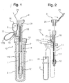
- an intermittent urethra self-retaining catheter set 10 of the present invention comprises a catheter unit 1, a disinfectant casing 2, and a cap 3.
- the catheter unit 1 includes a catheter body 11 having an urine-guiding passage 111 and a water-guiding passage 112 that extend along a longitudinal direction and are separated from each other, a balloon 12 attached to a distal end of the catheter body 11 in an inflatable manner and communicated to the water-guiding passage 112, an elastic plug 13 attached to an intermediate portion of the catheter body 11, a branched tube 14 bifurcated from the catheter body 11 above the elastic plug 13 and communicated to the water-guiding passage 112, a reservoir 16 attached to a free end of the branched tube 14 in a collapsible manner for storing a sterilized water, an on-off valve 17 attached to an intermediate portion of the branched tube 14, and a reinforcement tube 18 inserted into an upper interior of the urine-guiding passage 111 in the catheter body 11.
- the disinfectant casing 2 is detachably fitted on the elastic plug 13 in a sealing manner for containing a lower part of the catheter body 11 below the elastic plug 13 and for storing a disinfectant liquid 21.
- the cap 3 is detachably fitted on a top portion of the catheter body 11 for opening and closing the urine-guiding passage 111.
- the cap 3 can utilize the "CAP FOR MEDICAL APPLIANCE TO BE RETAINED IN HUMAN BODY" (Japanese Patent Public Disclosure No. HEI 9-206370(1997)) mentioned above. A detailed structure of the cap 3 will be described after by referring to Figures 7A, 7B, and 8.
- the elastic plug 13 is made of a flexible resin material or the like.
- the reservoir 16 is made of a flexible resin material such as PVC, polyurethane, or the like.
- the catheter body 11 and balloon 12 are made of conventional materials.
- the reinforcement tube 18 is made of a material harder than that of the catheter body 11 (for example, polytetrafluoroetylene, or the like).
- the sterilized water 15 may be conventional saline or the like.
- the disinfectant liquid 21 is preferably benzethonium chloride, for example, a mixture of Hyamine (trade name) sold by SANKYO CO., LTD. and sterilized glycerol liquid; benzallonium chloride, for example, Osvan (trade name) sold by NIHON PHARMACEUTICAL CO., LTD. and TAKEDA CHEMICAL INDUSTRIES, LTD.; or Povidone iodine, for example, Isodine (trade name) sold by MEIJI SEIKA KAISYA, LTD.
- FIGS 3A and 3B show an example of the on-off valve 17.
- the on-off valve 17 includes a valve body 171, a plunger 172, and a pull string 173.
- the valve body 171 includes a recess 1711 that supports the plunger 172 to permit the plunger 172 to reciprocate in the recess 1711 with a frictional resistance, a first tube 1712 communicated to the reservoir 16, and a second tube 1713 communicated to the branched tube 14.
- the plunger 172 includes a plunger body 1721 that can reciprocate in the recess 1711 with a frictional resistance, a flange 1722, and a communication hole 1723.
- the pull string 173 is bound on the flange 1722 of the plunger 172 to form a hoop.
- the on-off valve 17 is set to be in a position shown in Figure 3A under a normal condition. That is, the plunger body 1721 is inserted into a most inner part of the recess 1711 so that the plunger body 1721 shuts off a communication between the first and second tubes 1712 and 1713.
- the plunger body 1721 is drawn from the recess 1711 to the maximum extent so that the communication hole 1723 in the plunger body 1721 permits to communicate the first and second tubes 1712 and 1713 with each other.
- the sterilized water 15 can flow through the first tube 1712, communication hole 1723, and second tube 1713 between the reservoir 16 and the balloon 12.
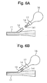
- an absorbing material 22, such as sponge or the like is mounted on an inner peripheral surface around an upper outlet of the disinfectant casing 2.
- the absorbing material 22 serves to absorb disinfectant liquid 21.
- the catheter body 11 rubs the inner surface of the absorbing material 21 to be sterilized.
- the disinfectant casing 2 may be formed into a U-shaped configuration. This configuration will be convenient for accommodation and portage.
- the absorbing material 22 shown in Figure 4 may be provided on an inner peripheral surface around an upper outlet of the U-shaped disinfectant casing 2 shown in Figure 5.
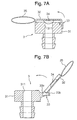
- the branched tube 14 may be detachably coupled to the catheter body 11 by a bamboo shoot type connector 141.
- a distal end of the catheter body 11 may be formed into a curved configuration. This configuration will make it easy to insert the catheter body 11 into a urethra.
- FIGS 7A and 7B show a first embodiment of a cap 3 of the present invention.
- the cap 3 includes a connection plug body 31, a lid body 32, and a hinge 33.
- the lid body 32 is coupled to the connection plug body 31 through the hinge 33.
- the connection plug body 31, hinge 33, and lid body 32 are integrally formed of the same synthetic resin material.
- the lid body 32 is provided on a central area of an inner surface thereof with an engaging member 34 made of a resilient material (for example, silicone rubber, polyethylene, or the like).
- the lid body 32 is provided on an end thereof with a pull string 35.
- the hinge 33 as shown in Figures 7A and 7B, includes a joint portion 33a which serves to join the lid body 32 to the connection plug body 31, and an elastically deformable portion 33b.
- the elastically deformable portion 33b actuates the lid body 32 to be closed by the elastic recovery force within a critical turning angle, but the portion 33b actuates the lid body 32 to be returned to the completely opened position by means of the buckling action of the portion 33b when the lid body 32 rotates over the critical turning angle (see Figure 7B).
- the engaging member 34 engages a peripheral edge of an outlet port 311 in the connection plug body 31 with the member 34 being resiliently deformed when the lid body 32 covers a top of the connection plug body 31, thereby maintaining the outlet port 311 in an airtight or liquid-tight condition.
- the lid body 32 can be easily opened and closed by hooking and pulling the pull string 35 by a person's palm or finger.
- the cap 3 may be used, for example, as shown in Figures 1 and 2.
- Figure 1 shows an example in which the cap 3 is attached to an external drain port of the catheter body 11 of the intermittent urethra self-retaining catheter set 10.
- connection plug body 31 shown in Figures 1 and 2 is coupled to an inside of a port of a mating appliance, the connection plug body 31 may be coupled to the outside of the port.
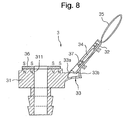
- Figure 8 shows a second embodiment of the cap 3.
- an annular magnet 36 is secured to the upper surface of the connection plug body 31 and another annular magnet 37 is secured to the inner face of the lid body 32 around the engaging member 34.
- the magnets 36 and 37 are set to be 5 to 15 mm in diameter, 0.5 to 5.0 mm in thickness, and 100 to 2000 gauss in magnetic flux density. Magnetic poles on contact surfaces of the magnets 36 and 37 are directed in opposition to each other.
- the upper and lower surfaces of the annular magnet 36 are set to be an S-pole and an N-pole while the upper and lower surfaces of the magnet 37 are set to be an N-pole and an S-pole.
- One of the annular magnets 36 and 37 may be replaced by an annular magnet made of a ferromagnetic material (for example, iron, samarium, nickel, cobalt, ferrite, or the like).
- the engaging member 34 closes the outlet port 311 in the connection plug body 31.
- the engaging member 34 inside the annular magnet 37 comes into contact with the inner peripheral edge of the annular magnet 36 and the inner peripheral edge of the outlet port 311 in the connection plug body 31, thereby enhancing the air and liquid sealing in the cap 3.
- the engaging member 34 serves to guide the magnet 37 upon interconnection of the magnets 36 and 37.
- the catheter unit 1 is removed from the disinfectant casing 2 and the catheter body 11 is inserted through a urethra into a bladder 5 ( Figure 10A).
- the balloon 12 is in a contracted position. Since the upper part of the catheter body 11 is reinforced by the reinforcement tube 18, a user can handle the catheter 11 readily without causing a proximate side of the catheter body 11 to be deformed irregularly.
- the on-off valve 17 is opened to return the sterilized water 15 from the balloon 12 to the reservoir 16. Then, the balloon 12 returns to the original contracted position and the on-off valve 17 is closed again. After using the catheter unit 1, it is inserted into the disinfectant casing 2, the cap 3 closes the outlet port 311 of the cap 3. Under this condition, the catheter set 10 is stored at a suitable place.
- the lid body 32 covers a top of the connection plug body 31 by means of an elastic recovery force of the hinge 33, so that the engaging member 34 engages with a peripheral edge of an outlet port 311 in the connection plug body 31 in an airtight manner.
- the engaging member 34 on the inner face of the lid body 32 is guided by the outlet port 311 in the connection plug body 31 to bring the lid body 32 into a regular position. Accordingly, the lid body 32 firmly engages the connection plug body 31 and leakage of urine can be prevented, since the engaging member seals the outlet port in an airtight or liquid-tight manner even if any clearance between the contact surfaces of the bodies 32 and 31 is caused.
- the lid body 32 In the case of opening the lid body 32, the lid body 32 will be opened by pulling the pull string strap 35 in the reverse direction against an elastic resistant force of the hinge 33. When the lid body 32 is turned over a critical angle, the lid body 32 is maintained in a completely open position by means of a buckling action of the hinge 33. Accordingly, it is not necessary for the user to intentionally keep the lid body 32 in the opened position.
- the catheter unit can be retained in the bladder, for example, during half-day (daytime or nighttime), it is unnecessary to use a napkin, to require nursing, care or the like during the half-day.
- half-day daytime or nighttime
- handling of the catheter set becomes more convenient, self-drainage can be done, and area of behavior for a user is not restrained. Since duration of time for retaining is relatively short, there is no possibility of urinary infectious disease.
- the intermittent urethra self-retaining set of the present invention is suitable for use by a patient suffered from a damaged spinal cord, a patient suffered from cerebrovascular disease, and a patient suffered from drainage disease due to congenital urethra deformity.
Abstract
Description
- This invention relates to an intermittent urethra self-retaining catheter set in which a catheter is retained in a urethra intermittently to carry out drainage and more particularly relates to an intermittent urethra self-retaining catheter set suitable for a physical exhaustion user or a hyposthenia user to use by oneself.
- There is a conventional catheter for purpose of urination to an end of which a balloon is attached. The balloon closely contacts with a catheter body during insertion into a urethra. In order to retain the catheter body in a bladder, sterilized water is injected through a proximal end of the catheter body into the balloon to inflate the balloon, thereby preventing a distal end of the catheter from coming out of the bladder. In the case where such catheter is used for a long period of time, a urinary infectious disease will occur and restrict behavior of a user.
- In order to prevent the urinary infection disease and ensure freedom of behavior for a user in a certain extent, a Nelaton's catheter to be used in a self-drainage method has been developed. Since this Nelaton's catheter is not provided on a distal end with a balloon, it is impossible to retain the catheter in a urethra for a long period of time. A user must always carry the Nelaton's catheter in a casing filled with disinfectant liquid. If desired, the user removes the Nelaton's catheter from the casing and inserts the catheter through the urethra into the bladder to drain urine by oneself.
- This Nelaton's catheter is inconvenient for a user, because the user must always carry it. It will be unnecessary for a patient suffered with a damaged spinal cord, a patient suffered with a cerebrovascular disease, or a patient suffered with a urination disease due to congenital urethra deformity to retain the catheter in the bladder, if the patient is awake, or if an attendant presents near the patient. On the other hand, if the attendant does not present near the patient, it will be necessary to retain the catheter in the patient's bladder.
- In order to obtain an intermittent urethra self-retaining catheter set that has a self-retaining function in a conventional catheter with a balloon and a self-drainage function in a conventional catheter with no balloon (Nelaton's catheter), the present applicant has proposed previously "INTERMITTENT URETHRA SELF-RETAINING CATHETER SET" (Japanese Utility Model Registered Publication No. 2587642). This intermittent urethra self-retaining catheter set comprises a catheter unit, a disinfectant casing, and a cap. The catheter unit includes a catheter body having an urine-guiding passage and a water-guiding passage that extend along a longitudinal direction and are separated from each other, a balloon attached to a distal end of the catheter body in an inflatable manner and communicated to the water-guiding passage, an elastic plug attached to an intermediate portion of the catheter body, a branched tube bifurcated from the catheter body above the elastic plug and communicated to the water-guiding passage, a reservoir attached to a free end of the branched tube in a collapsible manner for storing a sterilized water, and an on-off valve attached to an intermediate portion of the branched tube. The disinfectant casing is detachably fitted on the elastic plug in a sealing manner for containing a lower part of the catheter body below the elastic plug and for storing a disinfectant liquid. The cap is detachably fitted on a top portion of the elastic plug to cover a top of the catheter body above the elastic plug, the branched tube, the on-off valve, and the reservoir.
- Although this intermittent urethra self-retaining catheter set has achieved the initial object, it has not been still sufficient for, in particular, a physical exhaustion user or a hyposthenia user to use the catheter set by oneself. Since the catheter body is rich in flexibility, it is difficult for the user to insert the catheter body into the urethra. Furthermore, a user is required for a delicate technique and a slight force in patient's fingers in order to attach and detach the cap to and from the elastic plug and to open and close the on-off valve.
- On the other hand, the present applicant has proposed previously "CAP FOR MEDICAL APPLIANCE TO BE RETAINED IN HUMAN BODY" (Japanese Patent Public Publication No. HEI 9-206370 (1997)). The cap for a medical appliance to be retained in a human body is constructed to achieve an object in which the cap can be readily handled for charging and discharging urine even by, for example, a woman who retains urine in her bladder, a person who finds it difficult to discharge urine, or a person who uses urinary bladder bags or napkins due to incompleteness of urine, and which does not cause leakage of urine even if the contact surfaces become rough on account of urine crystals.
- The cap for a medical appliance to be retained in a human body includes a lid body, a connection plug body, and a hinge. The lid body is coupled to the connecting plug body through the hinge. The connection plug body, hinge, and lid body are integrally formed of the same synthetic resin material. The lid body is provided on a central area of an inner surface thereof with an engaging member made of a resilient material. The lid body is provided on an end thereof with a pull string.
- There will be a possibility of applying the cap for a medical appliance to be retained in a human body to the intermittent urethra self-retaining catheter set mentioned above.
- Accordingly, an object of the present invention is to provide an intermittent urethra self-retaining catheter set that has a self-retaining function in a conventional catheter with a balloon and a self-drainage function in a conventional catheter with no balloon (Nelaton's catheter) and that is suitable for a user in physical exhaustion or a user in hyposthenia to use by oneself.
- In order to achieve the above object, an intermittent urethra self-retaining catheter set in accordance with the present invention comprises a catheter unit, a disinfectant casing, and a cap. The catheter unit includes a catheter body having an urine-guiding passage and a water-guiding passage that extend along a longitudinal direction and are separated from each other, a balloon attached to a distal end of the catheter body in an inflatable manner and communicated to the water-guiding passage, an elastic plug attached to an intermediate portion of the catheter body, a branched tube bifurcated from the catheter body above the elastic plug and communicated to the water-guiding passage, a reservoir attached to a free end of the branched tube in a collapsible manner for storing a sterilized water, an on-off valve attached to an intermediate portion of the branched tube, and a reinforcement tube inserted into an upper interior of the urine-guiding passage in the catheter body. The disinfectant casing is detachably fitted on the elastic plug in a sealing manner for containing a lower part of the catheter body below the elastic plug and for storing a disinfectant liquid. The cap is detachably fitted on a top portion of the catheter body for opening and closing an outlet port. The on-off valve is adapted to open and close a passage in which the sterilized water flows between the reservoir and the balloon. The branched tube may be detachably connected to the catheter body.
- The cap includes a connection plug body, a hinge section, and a lid that are made of a synthetic resin material integrally together with one another. An engaging member made of a flexible material is mounted on a central portion of an inner surface of the lid. A pull string is attached to an end of the lid. A first annular magnet may be secured to a top surface of the connection plug body and a second annular magnet may be secured to an inner surface of the lid to surround the engaging member.
- The on-off valve includes a valve body, a plunger, and a pull string. The valve body includes a recess that supports the plunger to permit the plunger to reciprocate in the recess with a frictional resistance, a first tube communicated to the reservoir, and a second tube communicated to the branched tube. The plunger includes a plunger body that can reciprocate in the recess with a frictional resistance, a flange, and a communication hole. The pull string is bound on the flange of the plunger to form a hoop.
- An absorbing material may be mounted on an inner peripheral surface around an upper outlet of the disinfectant casing. A distal end of the catheter body may be formed into a curved configuration.
-
- Figure 1 is a longitudinal section view of an intermittent urethra self-retaining catheter set in accordance with the present invention;
- Figure 2 is an exploded longitudinal section view of the catheter set shown in Figure 1;
- Figure 3A is a longitudinal section view of an on-off valve to be used in the catheter set of the present invention, illustrating the on-off valve in a closed position;
- Figure 3B is a view similar to Figure 3A, illustrating the on-off valve in an opened position;
- Figure 4 is a longitudinal section view of another embodiment of a disinfectant casing that is one of constituents of the catheter set in accordance with the present invention;
- Figure 5 is a longitudinal section view of still another embodiment of a disinfectant casing that is one of constituents of the catheter set in accordance with the present invention;
- Figure 6A is a side elevation view of another embodiment of a branched tube that is one of constituents of the catheter set in accordance with the present invention, illustrating the branched tube separated from a catheter body;
- Figure 6B is a view similar to Figure 6A, illustrating the branched tube joined to the catheter body;
- Figure 7A a longitudinal section view of a cap that is one of constituents of the catheter set in accordance with the present invention, illustrating the cap in a closed position;
- Figure 7B is a view similar to Figure 7A, illustrating the cap in an opened position;
- Figure 8 a longitudinal section view of another embodiment of a cap that is one of constituents of the catheter set in accordance with the present invention, illustrating the cap in an opened position;
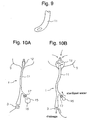
- Figure 9 is a plan view of a distal end of the catheter body that is one of constituents of the catheter set in accordance with the present invention;
- Figure 10A is an explanatory view of an example of use of the catheter set in accordance with the present invention, illustrating a position where the catheter body has been just inserted into a bladder; and
- Figure 10B is a view similar to Figure 10A, illustrating a position where the catheter body is retained in the bladder.
- Referring now to the drawings, a preferred embodiment of an intermittent urethra self-retaining catheter set in accordance with the present invention will be described below. As shown in Figures 1 and 2, an intermittent urethra self-retaining catheter set 10 of the present invention comprises a
catheter unit 1, adisinfectant casing 2, and acap 3. - The
catheter unit 1 includes acatheter body 11 having an urine-guidingpassage 111 and a water-guidingpassage 112 that extend along a longitudinal direction and are separated from each other, aballoon 12 attached to a distal end of thecatheter body 11 in an inflatable manner and communicated to the water-guidingpassage 112, anelastic plug 13 attached to an intermediate portion of thecatheter body 11, abranched tube 14 bifurcated from thecatheter body 11 above theelastic plug 13 and communicated to the water-guidingpassage 112, areservoir 16 attached to a free end of the branchedtube 14 in a collapsible manner for storing a sterilized water, an on-offvalve 17 attached to an intermediate portion of the branchedtube 14, and areinforcement tube 18 inserted into an upper interior of the urine-guidingpassage 111 in thecatheter body 11. - The
disinfectant casing 2 is detachably fitted on theelastic plug 13 in a sealing manner for containing a lower part of thecatheter body 11 below theelastic plug 13 and for storing adisinfectant liquid 21. - The
cap 3 is detachably fitted on a top portion of thecatheter body 11 for opening and closing the urine-guidingpassage 111. Thecap 3 can utilize the "CAP FOR MEDICAL APPLIANCE TO BE RETAINED IN HUMAN BODY" (Japanese Patent Public Disclosure No. HEI 9-206370(1997)) mentioned above. A detailed structure of thecap 3 will be described after by referring to Figures 7A, 7B, and 8. - The
elastic plug 13 is made of a flexible resin material or the like. Thereservoir 16 is made of a flexible resin material such as PVC, polyurethane, or the like. Thecatheter body 11 andballoon 12 are made of conventional materials. Thereinforcement tube 18 is made of a material harder than that of the catheter body 11 (for example, polytetrafluoroetylene, or the like). - The sterilized
water 15 may be conventional saline or the like. Thedisinfectant liquid 21 is preferably benzethonium chloride, for example, a mixture of Hyamine (trade name) sold by SANKYO CO., LTD. and sterilized glycerol liquid; benzallonium chloride, for example, Osvan (trade name) sold by NIHON PHARMACEUTICAL CO., LTD. and TAKEDA CHEMICAL INDUSTRIES, LTD.; or Povidone iodine, for example, Isodine (trade name) sold by MEIJI SEIKA KAISYA, LTD. - Figures 3A and 3B show an example of the on-off
valve 17. The on-offvalve 17 includes avalve body 171, aplunger 172, and apull string 173. Thevalve body 171 includes arecess 1711 that supports theplunger 172 to permit theplunger 172 to reciprocate in therecess 1711 with a frictional resistance, afirst tube 1712 communicated to thereservoir 16, and asecond tube 1713 communicated to the branchedtube 14. Theplunger 172 includes aplunger body 1721 that can reciprocate in therecess 1711 with a frictional resistance, aflange 1722, and acommunication hole 1723. Thepull string 173 is bound on theflange 1722 of theplunger 172 to form a hoop. - The on-off
valve 17 is set to be in a position shown in Figure 3A under a normal condition. That is, theplunger body 1721 is inserted into a most inner part of therecess 1711 so that theplunger body 1721 shuts off a communication between the first andsecond tubes pull string 173 is pulled, as shown in Figure 3B, theplunger body 1721 is drawn from therecess 1711 to the maximum extent so that thecommunication hole 1723 in theplunger body 1721 permits to communicate the first andsecond tubes water 15 can flow through thefirst tube 1712,communication hole 1723, andsecond tube 1713 between thereservoir 16 and theballoon 12. - As shown in Figure 4, an absorbing
material 22, such as sponge or the like is mounted on an inner peripheral surface around an upper outlet of thedisinfectant casing 2. The absorbingmaterial 22 serves to absorbdisinfectant liquid 21. When thecatheter body 11 comes out from and enters thedisinfectant casing 2, thecatheter body 11 rubs the inner surface of the absorbingmaterial 21 to be sterilized. Thus, it is unnecessary to fill thedisinfectant liquid 21 in thedisinfectant casing 2. Also, as shown in Figure 5, thedisinfectant casing 2 may be formed into a U-shaped configuration. This configuration will be convenient for accommodation and portage. The absorbingmaterial 22 shown in Figure 4 may be provided on an inner peripheral surface around an upper outlet of theU-shaped disinfectant casing 2 shown in Figure 5. - As shown in Figures 6A and 6B, the branched
tube 14 may be detachably coupled to thecatheter body 11 by a bambooshoot type connector 141. - As shown in Figure 9, a distal end of the
catheter body 11 may be formed into a curved configuration. This configuration will make it easy to insert thecatheter body 11 into a urethra. - Referring now to Figures 7A, 7B, and 8, a detailed structure of the
cap 3 will be explained below. Figures 7A and 7B show a first embodiment of acap 3 of the present invention. Thecap 3 includes aconnection plug body 31, alid body 32, and ahinge 33. Thelid body 32 is coupled to theconnection plug body 31 through thehinge 33. In thecap 3, theconnection plug body 31,hinge 33, andlid body 32 are integrally formed of the same synthetic resin material. Thelid body 32 is provided on a central area of an inner surface thereof with an engagingmember 34 made of a resilient material (for example, silicone rubber, polyethylene, or the like). Thelid body 32 is provided on an end thereof with apull string 35. - The
hinge 33, as shown in Figures 7A and 7B, includes ajoint portion 33a which serves to join thelid body 32 to theconnection plug body 31, and an elasticallydeformable portion 33b. The elasticallydeformable portion 33b actuates thelid body 32 to be closed by the elastic recovery force within a critical turning angle, but theportion 33b actuates thelid body 32 to be returned to the completely opened position by means of the buckling action of theportion 33b when thelid body 32 rotates over the critical turning angle (see Figure 7B). - As shown in Figure 7A, the engaging
member 34 engages a peripheral edge of anoutlet port 311 in theconnection plug body 31 with themember 34 being resiliently deformed when thelid body 32 covers a top of theconnection plug body 31, thereby maintaining theoutlet port 311 in an airtight or liquid-tight condition. - Even if a person has limited use of hands or fingers, the
lid body 32 can be easily opened and closed by hooking and pulling thepull string 35 by a person's palm or finger. - The
cap 3 may be used, for example, as shown in Figures 1 and 2. Figure 1 shows an example in which thecap 3 is attached to an external drain port of thecatheter body 11 of the intermittent urethra self-retaining catheter set 10. Although theconnection plug body 31 shown in Figures 1 and 2 is coupled to an inside of a port of a mating appliance, theconnection plug body 31 may be coupled to the outside of the port. - Figure 8 shows a second embodiment of the
cap 3. In the second embodiment, anannular magnet 36 is secured to the upper surface of theconnection plug body 31 and anotherannular magnet 37 is secured to the inner face of thelid body 32 around the engagingmember 34. Themagnets magnets annular magnet 36 are set to be an S-pole and an N-pole while the upper and lower surfaces of themagnet 37 are set to be an N-pole and an S-pole. One of theannular magnets - As shown in Figure 8, when the
cap 3 is in an opened position, theannular magnet 36 releases theoutlet port 311 in theconnection plug body 31 while themagnet 37 is spaced away from theplug body 31. When thecap 3 is in a closed position similar to Figure 7A, bothmagnets magnets magnets magnets member 34 can automatically correct the misalignment by a manner described above. - When the
cap 3 is in the closed position as shown in Figure 1, the engagingmember 34 closes theoutlet port 311 in theconnection plug body 31. When themagnets member 34 inside theannular magnet 37 comes into contact with the inner peripheral edge of theannular magnet 36 and the inner peripheral edge of theoutlet port 311 in theconnection plug body 31, thereby enhancing the air and liquid sealing in thecap 3. In addition, the engagingmember 34 serves to guide themagnet 37 upon interconnection of themagnets - By referring to Figures 10A and 10B, an example of use of the intermittent urethra self-retaining catheter set 10 in accordance with the present invention will be explained below. Firstly, the
catheter unit 1 is removed from thedisinfectant casing 2 and thecatheter body 11 is inserted through a urethra into a bladder 5 (Figure 10A). At this time, theballoon 12 is in a contracted position. Since the upper part of thecatheter body 11 is reinforced by thereinforcement tube 18, a user can handle thecatheter 11 readily without causing a proximate side of thecatheter body 11 to be deformed irregularly. - Secondly, the user pulls the pull string 173 (Figure 1) of the on-off
valve 17 to bring the on-offvalve 17 into an opened position (Figure 3B). When thereservoir 16 is compressed manually, sterilizedwater 15 in thereservoir 16 flows into theballoon 12 to inflate the balloon 12 (Figure 10B). Then, the user pushes theplunger 172 of the on-offvalve 17 manually into thevalve body 171 to bring the on-offvalve 17 into a closed position (Figure 3A). Consequently, theballoon 12 keeps its inflation. - The inflation of the
balloon 12 retains thecatheter unit 1 in thebladder 5. Next, the user pulls thepull string 35 of thecap 3 to open theoutlet port 311 in thecap 3. Urine in thebladder 5 is drained through the urine-guiding passage 111 (Figure 1) from theoutlet port 311 to the outside. - When the retention is finished, the on-off
valve 17 is opened to return the sterilizedwater 15 from theballoon 12 to thereservoir 16. Then, theballoon 12 returns to the original contracted position and the on-offvalve 17 is closed again. After using thecatheter unit 1, it is inserted into thedisinfectant casing 2, thecap 3 closes theoutlet port 311 of thecap 3. Under this condition, the catheter set 10 is stored at a suitable place. - In the
cap 3, when a disabled patient hooks thepull string 35 to one's palm or finger toward theconnection plug body 31, thelid body 32 covers a top of theconnection plug body 31 by means of an elastic recovery force of thehinge 33, so that the engagingmember 34 engages with a peripheral edge of anoutlet port 311 in theconnection plug body 31 in an airtight manner. At this time, even if thelid body 32 moves eccentrically, the engagingmember 34 on the inner face of thelid body 32 is guided by theoutlet port 311 in theconnection plug body 31 to bring thelid body 32 into a regular position. Accordingly, thelid body 32 firmly engages theconnection plug body 31 and leakage of urine can be prevented, since the engaging member seals the outlet port in an airtight or liquid-tight manner even if any clearance between the contact surfaces of thebodies - In the case of opening the
lid body 32, thelid body 32 will be opened by pulling thepull string strap 35 in the reverse direction against an elastic resistant force of thehinge 33. When thelid body 32 is turned over a critical angle, thelid body 32 is maintained in a completely open position by means of a buckling action of thehinge 33. Accordingly, it is not necessary for the user to intentionally keep thelid body 32 in the opened position. - According to the intermittent urethra self-retaining catheter set, the catheter unit can be retained in the bladder, for example, during half-day (daytime or nighttime), it is unnecessary to use a napkin, to require nursing, care or the like during the half-day. On the other hand, handling of the catheter set becomes more convenient, self-drainage can be done, and area of behavior for a user is not restrained. Since duration of time for retaining is relatively short, there is no possibility of urinary infectious disease.
- The intermittent urethra self-retaining set of the present invention is suitable for use by a patient suffered from a damaged spinal cord, a patient suffered from cerebrovascular disease, and a patient suffered from drainage disease due to congenital urethra deformity.
Claims (7)
- An intermittent urethra self-retaining catheter set comprising a catheter unit, a disinfectant casing, and a cap;said catheter unit including: a catheter body having an urine-guiding passage and a water-guiding passage that extend along a longitudinal direction and are separated from each other, a balloon attached to a distal end of said catheter body in an inflatable manner and communicated to said water-guiding passage, an elastic plug attached to an intermediate portion of said catheter body, a branched tube bifurcated from said catheter body above said elastic plug and communicated to said water-guiding passage, a reservoir attached to a free end of said branched tube in a collapsible manner for storing a sterilized water, an on-off valve attached to an intermediate portion of said branched tube, and a reinforcement tube inserted into an upper interior of said urine-guiding passage in said catheter body;said disinfectant casing being detachably fitted on said elastic plug in a sealing manner for containing a lower part of said catheter body below said elastic plug and for storing a disinfectant liquid;said cap being detachably fitted on a top portion of said catheter body for opening and closing an outlet port; andsaid on-off valve being adapted to open and close a passage in which said sterilized water flows between said reservoir and said balloon.
- A catheter set according to Claim 1 wherein said branched tube is detachably connected to said catheter body.
- A catheter set according to Claim 1 wherein said cap includes a connection plug body, a hinge section, and a lid that are made of a synthetic resin material integrally together with one another, wherein an engaging member made of a flexible material is mounted on a central portion of an inner surface of said lid, and wherein a pull string is attached to an end of said lid.
- A catheter set according to Claim 3 wherein a first annular magnet is secured to a top surface of said connection plug body and a second annular magnet is secured to an inner surface of said lid to surround said engaging member.
- A catheter set according to Claim 1 wherein said on-off valve includes a valve body, a plunger, and a pull string, wherein said valve body includes a recess that supports said plunger to permit said plunger to reciprocate in said recess with a frictional resistance, a first tube communicated to said reservoir, and a second tube communicated to said branched tube, wherein said plunger includes a plunger body that can reciprocate in said recess with a frictional resistance, a flange, and a communication hole, and wherein said pull string is bound on said flange of said plunger to form a hoop.
- A catheter set according to Claim 1 wherein an absorbing material is mounted on an inner peripheral surface around an upper outlet of said disinfectant casing.
- A catheter set according to Claim 1 wherein a distal end of said catheter body is formed into a curved configuration.
Applications Claiming Priority (1)
| Application Number | Priority Date | Filing Date | Title |
|---|---|---|---|
| PCT/JP2003/010563 WO2005018714A1 (en) | 2003-08-21 | 2003-08-21 | Intermittent urethra-indwelling catheter set |
Publications (3)
| Publication Number | Publication Date |
|---|---|
| EP1671663A1 true EP1671663A1 (en) | 2006-06-21 |
| EP1671663A4 EP1671663A4 (en) | 2007-05-30 |
| EP1671663B1 EP1671663B1 (en) | 2009-03-04 |
Family
ID=34204200
Family Applications (1)
| Application Number | Title | Priority Date | Filing Date |
|---|---|---|---|
| EP03818285A Expired - Lifetime EP1671663B1 (en) | 2003-08-21 | 2003-08-21 | Intermittent urethra self-retaining catheter set |
Country Status (5)
| Country | Link |
|---|---|
| US (1) | US7537589B2 (en) |
| EP (1) | EP1671663B1 (en) |
| JP (1) | JP4359285B2 (en) |
| DE (1) | DE60326495D1 (en) |
| WO (1) | WO2005018714A1 (en) |
Cited By (11)
| Publication number | Priority date | Publication date | Assignee | Title |
|---|---|---|---|---|
| US10183112B2 (en) | 2013-08-30 | 2019-01-22 | Hollister Incorporated | Device for trans anal irrigation |
| US10561817B2 (en) | 2014-05-30 | 2020-02-18 | Hollister Incorporated | Flip open catheter package |
| US10737013B2 (en) | 2014-07-08 | 2020-08-11 | Hollister Incorporated | Portable trans anal irrigation device |
| US10765796B2 (en) | 2014-07-08 | 2020-09-08 | Hollister Incorporated | Trans anal irrigation platform with bed module |
| US11020561B2 (en) | 2016-04-22 | 2021-06-01 | Hollister Incorporated | Medical device package with a twist cap |
| US11103676B2 (en) | 2016-04-22 | 2021-08-31 | Hollister Incorporated | Medical device package with flip cap having a snap fit |
| US11383021B2 (en) | 2016-07-08 | 2022-07-12 | Hollister Incorporated | Wireless electronic pump design for a body cavity irrigation device |
| US11497844B2 (en) | 2016-12-14 | 2022-11-15 | Hollister Incorporated | Transanal irrigation device and system |
| US11666730B2 (en) | 2017-12-08 | 2023-06-06 | Hollister Incorporated | Package for medical device for ergonomic device removal |
| US11707599B2 (en) | 2017-02-21 | 2023-07-25 | Hollister Incorporated | Medical device package with twist-off cap |
| US11771865B2 (en) | 2017-10-25 | 2023-10-03 | Hollister Incorporated | Caps for catheter packages |
Families Citing this family (18)
| Publication number | Priority date | Publication date | Assignee | Title |
|---|---|---|---|---|
| US8328792B2 (en) | 2005-10-27 | 2012-12-11 | C. R. Bard, Inc. | Enhanced pre-wetted intermittent catheter with lubricious coating |
| EP2146770A4 (en) * | 2007-05-17 | 2015-12-30 | Univ South Florida | Bladder drainage aid |
| US9279527B2 (en) * | 2008-05-30 | 2016-03-08 | Hana Consulting, Inc. | Magnetic capping device and method |
| JP2013500125A (en) | 2009-07-29 | 2013-01-07 | シー・アール・バード・インコーポレーテッド | Improved drainage device and / or catheter with retractable sleeve and method of using the same |
| WO2011019359A1 (en) | 2009-08-13 | 2011-02-17 | C. R. Bard, Inc. | Catheter having internal hydrating fluid storage and/or catheter package using the same and method of making and/or using the same |
| US8500684B2 (en) * | 2009-09-18 | 2013-08-06 | Bruce A. Gardner | Balloon catheter |
| US10912917B2 (en) | 2009-12-23 | 2021-02-09 | C. R. Bard, Inc. | Catheter assembly/package utilizing a hydrating/hydrogel sleeve and method of making and using the same |
| EP2542291A4 (en) | 2010-03-04 | 2013-08-07 | Bard Inc C R | Catheter assembly/package utilizing a hydrating/hydrogel sleeve and a foil outer layer and method of making and using the same |
| US8827985B1 (en) * | 2013-03-01 | 2014-09-09 | Henry Allison BARNETT | Non-bladder invasive urethral catheter system |
| US8998882B2 (en) | 2013-03-13 | 2015-04-07 | C. R. Bard, Inc. | Enhanced pre-wetted intermittent catheter with lubricious coating |
| US9199060B1 (en) * | 2013-06-25 | 2015-12-01 | Henry Allison BARNETT | Non-bladder invasive urethral catheter system |
| KR102365043B1 (en) | 2015-03-03 | 2022-02-17 | 가부시키가이샤 츠카다 메디칼 리서치 | Units for balloon catheters and urethral indwelling balloon catheters |
| US11400257B2 (en) | 2017-11-13 | 2022-08-02 | Teleflex Life Sciences Pte. Ltd. | Frictionless catheter |
| US11786620B2 (en) | 2018-04-30 | 2023-10-17 | CathBuddy, Inc. | Handheld cleaner-disinfector for medical devices |
| US10639389B2 (en) | 2018-04-30 | 2020-05-05 | CathBuddy, Inc | Methods and devices for portable sterilization and containment of medical devices |
| CN110860002A (en) * | 2018-08-28 | 2020-03-06 | 慈济学校财团法人慈济科技大学 | Portable catheter |
| CN110403748A (en) * | 2019-08-28 | 2019-11-05 | 中南大学湘雅二医院 | A kind of ureter seal cap |
| CN113521493A (en) * | 2021-06-17 | 2021-10-22 | 浙江优特格尔医疗用品有限公司 | Hydrophilic catheter convenient to use and capable of preventing liquid from overflowing |
Citations (5)
| Publication number | Priority date | Publication date | Assignee | Title |
|---|---|---|---|---|
| EP0371497A1 (en) * | 1988-11-29 | 1990-06-06 | Terumo Kabushiki Kaisha | Urethra catheter and manufacturing method therefor |
| JP2587642Y2 (en) * | 1992-06-19 | 1998-10-16 | 株式会社塚田メディカル・リサーチ | Intermittent urethral indwelling catheter set |
| US5916195A (en) * | 1998-02-04 | 1999-06-29 | Argomed Ltd. | Internal catheter |
| EP1090656A1 (en) * | 1999-10-06 | 2001-04-11 | Tsukada Medical Research Co., Ltd. | Catheter for intermittent self-conduction of urine |
| US20030153899A1 (en) * | 1998-02-04 | 2003-08-14 | Uzi Eshel | Urethral catheter and guide |
Family Cites Families (11)
| Publication number | Priority date | Publication date | Assignee | Title |
|---|---|---|---|---|
| US1486957A (en) * | 1922-06-15 | 1924-03-18 | Arthur E England | Toothbrush container |
| US2088678A (en) * | 1937-04-05 | 1937-08-03 | Josephine M Wylie | Absorbent cotton device for bottles |
| FI69351C (en) * | 1979-01-22 | 1986-01-10 | Jan Axel Svensson | SLIDVENTIL- OCH KOPPLINGSAGGREGAT |
| US5188593A (en) * | 1988-04-21 | 1993-02-23 | Vas-Cath Incorporated | Dual lumen catheter |
| US5569184A (en) * | 1992-04-29 | 1996-10-29 | Cardiovascular Dynamics, Inc. | Delivery and balloon dilatation catheter and method of using |
| DE69509827T2 (en) * | 1994-07-04 | 1999-10-07 | Tsukada Medical Research Co | Magnetic cap for a medical device |
| US6162201A (en) * | 1995-12-01 | 2000-12-19 | Cohen; Kenneth L. | Internal urinary catheter |
| JPH09206370A (en) * | 1995-12-01 | 1997-08-12 | Tsukada Medical Res:Kk | Cap for human body indwelling medical device |
| CA2169699A1 (en) * | 1995-12-01 | 1997-06-02 | Osamu Tsukada | Cap for medical appliance to be retained in human body |
| WO1997028840A1 (en) | 1996-02-12 | 1997-08-14 | Mentor Urology, Inc. | Prostatic tissue expander |
| JP2001309973A (en) | 2000-05-01 | 2001-11-06 | Jms Co Ltd | Connector cap |
-
2003
- 2003-08-21 EP EP03818285A patent/EP1671663B1/en not_active Expired - Lifetime
- 2003-08-21 JP JP2005508185A patent/JP4359285B2/en not_active Expired - Lifetime
- 2003-08-21 WO PCT/JP2003/010563 patent/WO2005018714A1/en active Application Filing
- 2003-08-21 DE DE60326495T patent/DE60326495D1/en not_active Expired - Lifetime
- 2003-08-21 US US10/568,434 patent/US7537589B2/en not_active Expired - Lifetime
Patent Citations (5)
| Publication number | Priority date | Publication date | Assignee | Title |
|---|---|---|---|---|
| EP0371497A1 (en) * | 1988-11-29 | 1990-06-06 | Terumo Kabushiki Kaisha | Urethra catheter and manufacturing method therefor |
| JP2587642Y2 (en) * | 1992-06-19 | 1998-10-16 | 株式会社塚田メディカル・リサーチ | Intermittent urethral indwelling catheter set |
| US5916195A (en) * | 1998-02-04 | 1999-06-29 | Argomed Ltd. | Internal catheter |
| US20030153899A1 (en) * | 1998-02-04 | 2003-08-14 | Uzi Eshel | Urethral catheter and guide |
| EP1090656A1 (en) * | 1999-10-06 | 2001-04-11 | Tsukada Medical Research Co., Ltd. | Catheter for intermittent self-conduction of urine |
Non-Patent Citations (1)
| Title |
|---|
| See also references of WO2005018714A1 * |
Cited By (16)
| Publication number | Priority date | Publication date | Assignee | Title |
|---|---|---|---|---|
| US10183112B2 (en) | 2013-08-30 | 2019-01-22 | Hollister Incorporated | Device for trans anal irrigation |
| US11116891B2 (en) | 2013-08-30 | 2021-09-14 | Hollister Incorporated | Device for trans anal irrigation |
| US10561817B2 (en) | 2014-05-30 | 2020-02-18 | Hollister Incorporated | Flip open catheter package |
| US11534573B2 (en) | 2014-05-30 | 2022-12-27 | Hollister Incorporated | Flip open catheter package |
| US11497845B2 (en) | 2014-07-08 | 2022-11-15 | Hollister Incorporated | Trans anal irrigation platform with bed module |
| US10737013B2 (en) | 2014-07-08 | 2020-08-11 | Hollister Incorporated | Portable trans anal irrigation device |
| US10765796B2 (en) | 2014-07-08 | 2020-09-08 | Hollister Incorporated | Trans anal irrigation platform with bed module |
| US11020561B2 (en) | 2016-04-22 | 2021-06-01 | Hollister Incorporated | Medical device package with a twist cap |
| US11103676B2 (en) | 2016-04-22 | 2021-08-31 | Hollister Incorporated | Medical device package with flip cap having a snap fit |
| US11813409B2 (en) | 2016-04-22 | 2023-11-14 | Hollister Incorporated | Medical device package with flip cap having a snap fit |
| US11833312B2 (en) | 2016-04-22 | 2023-12-05 | Hollister Incorporated | Medical device package with flip cap having a snap fit |
| US11383021B2 (en) | 2016-07-08 | 2022-07-12 | Hollister Incorporated | Wireless electronic pump design for a body cavity irrigation device |
| US11497844B2 (en) | 2016-12-14 | 2022-11-15 | Hollister Incorporated | Transanal irrigation device and system |
| US11707599B2 (en) | 2017-02-21 | 2023-07-25 | Hollister Incorporated | Medical device package with twist-off cap |
| US11771865B2 (en) | 2017-10-25 | 2023-10-03 | Hollister Incorporated | Caps for catheter packages |
| US11666730B2 (en) | 2017-12-08 | 2023-06-06 | Hollister Incorporated | Package for medical device for ergonomic device removal |
Also Published As
| Publication number | Publication date |
|---|---|
| DE60326495D1 (en) | 2009-04-16 |
| EP1671663B1 (en) | 2009-03-04 |
| EP1671663A4 (en) | 2007-05-30 |
| JP4359285B2 (en) | 2009-11-04 |
| US7537589B2 (en) | 2009-05-26 |
| WO2005018714A1 (en) | 2005-03-03 |
| JPWO2005018714A1 (en) | 2006-10-19 |
| US20080051762A1 (en) | 2008-02-28 |
Similar Documents
| Publication | Publication Date | Title |
|---|---|---|
| EP1671663B1 (en) | Intermittent urethra self-retaining catheter set | |
| US5817067A (en) | Cap for medical appliance to be retained in human body | |
| US20200345977A1 (en) | Urinary catheter assembly having a sleeve attached between a connector and a handle | |
| US5624410A (en) | Magnetic cap for medical appliance to be retained in human body | |
| US6527702B2 (en) | Urinary flow control device and method | |
| US3503400A (en) | Urethral valve | |
| US4968294A (en) | Urinary control valve and method of using same | |
| US5513659A (en) | Incontinence device | |
| CN103974739B (en) | Liquid-stopping device | |
| US20240068587A1 (en) | Valve for Regulating the Flow of A Liquid | |
| US20060142737A1 (en) | Catheter | |
| CN113164277B (en) | Urine collecting bag | |
| WO1992017137A1 (en) | Stoma cap | |
| CN114845764A (en) | Catheter with snap connector | |
| EP0265207A1 (en) | Trans-urethral incontinence device | |
| US5897540A (en) | Device for the drainage of uncontrolled urine release | |
| EP0506920B1 (en) | Urinary control with inflatable seal | |
| SI9600124A (en) | Prosthesis for bowel evacuation control - colostomy tube | |
| US11951028B2 (en) | Method for assembling a drain assembly and method for elimination of urine waste from an ostomy bag | |
| JPH09206370A (en) | Cap for human body indwelling medical device | |
| US20210244912A1 (en) | Indwelling urinary catheters | |
| CN210205443U (en) | Connector and catheter | |
| US20220142810A1 (en) | Female Urinary Catheter System | |
| JPH063347U (en) | Intermittent urethral indwelling catheter set | |
| CN210056419U (en) | Diarrhea patient makes a mouthful measurement bag |
Legal Events
| Date | Code | Title | Description |
|---|---|---|---|
| PUAI | Public reference made under article 153(3) epc to a published international application that has entered the european phase |
Free format text: ORIGINAL CODE: 0009012 |
|
| 17P | Request for examination filed |
Effective date: 20060309 |
|
| AK | Designated contracting states |
Kind code of ref document: A1 Designated state(s): DE FR IT |
|
| DAX | Request for extension of the european patent (deleted) | ||
| RBV | Designated contracting states (corrected) |
Designated state(s): DE FR IT |
|
| RIC1 | Information provided on ipc code assigned before grant |
Ipc: A61M 25/00 20060101AFI20070417BHEP Ipc: A61M 1/00 20060101ALI20070417BHEP Ipc: A61M 25/10 20060101ALI20070417BHEP |
|
| A4 | Supplementary search report drawn up and despatched |
Effective date: 20070426 |
|
| 17Q | First examination report despatched |
Effective date: 20080331 |
|
| GRAP | Despatch of communication of intention to grant a patent |
Free format text: ORIGINAL CODE: EPIDOSNIGR1 |
|
| GRAS | Grant fee paid |
Free format text: ORIGINAL CODE: EPIDOSNIGR3 |
|
| GRAA | (expected) grant |
Free format text: ORIGINAL CODE: 0009210 |
|
| AK | Designated contracting states |
Kind code of ref document: B1 Designated state(s): DE FR IT |
|
| REF | Corresponds to: |
Ref document number: 60326495 Country of ref document: DE Date of ref document: 20090416 Kind code of ref document: P |
|
| PLBE | No opposition filed within time limit |
Free format text: ORIGINAL CODE: 0009261 |
|
| STAA | Information on the status of an ep patent application or granted ep patent |
Free format text: STATUS: NO OPPOSITION FILED WITHIN TIME LIMIT |
|
| 26N | No opposition filed |
Effective date: 20091207 |
|
| PG25 | Lapsed in a contracting state [announced via postgrant information from national office to epo] |
Ref country code: IT Free format text: LAPSE BECAUSE OF NON-PAYMENT OF DUE FEES Effective date: 20090821 |
|
| PGRI | Patent reinstated in contracting state [announced from national office to epo] |
Ref country code: IT Effective date: 20110616 |
|
| REG | Reference to a national code |
Ref country code: FR Ref legal event code: PLFP Year of fee payment: 14 |
|
| REG | Reference to a national code |
Ref country code: FR Ref legal event code: PLFP Year of fee payment: 15 |
|
| REG | Reference to a national code |
Ref country code: FR Ref legal event code: PLFP Year of fee payment: 16 |
|
| PGFP | Annual fee paid to national office [announced via postgrant information from national office to epo] |
Ref country code: IT Payment date: 20220809 Year of fee payment: 20 Ref country code: DE Payment date: 20220628 Year of fee payment: 20 |
|
| PGFP | Annual fee paid to national office [announced via postgrant information from national office to epo] |
Ref country code: FR Payment date: 20220808 Year of fee payment: 20 |
|
| REG | Reference to a national code |
Ref country code: DE Ref legal event code: R071 Ref document number: 60326495 Country of ref document: DE |