EP1675314A1 - Ping Feature for Electronic Devices - Google Patents
Ping Feature for Electronic Devices Download PDFInfo
- Publication number
- EP1675314A1 EP1675314A1 EP04106973A EP04106973A EP1675314A1 EP 1675314 A1 EP1675314 A1 EP 1675314A1 EP 04106973 A EP04106973 A EP 04106973A EP 04106973 A EP04106973 A EP 04106973A EP 1675314 A1 EP1675314 A1 EP 1675314A1
- Authority
- EP
- European Patent Office
- Prior art keywords
- ping
- electronic device
- pingable
- computer readable
- code means
- Prior art date
- Legal status (The legal status is an assumption and is not a legal conclusion. Google has not performed a legal analysis and makes no representation as to the accuracy of the status listed.)
- Granted
Links
- 230000002093 peripheral effect Effects 0.000 claims description 76
- 238000004891 communication Methods 0.000 claims description 27
- 230000000881 depressing effect Effects 0.000 description 8
- 238000012360 testing method Methods 0.000 description 5
- 238000000034 method Methods 0.000 description 4
- 230000005540 biological transmission Effects 0.000 description 3
- 238000010586 diagram Methods 0.000 description 3
- 230000000977 initiatory effect Effects 0.000 description 3
- 238000003908 quality control method Methods 0.000 description 3
- 238000003860 storage Methods 0.000 description 2
- XUIMIQQOPSSXEZ-UHFFFAOYSA-N Silicon Chemical compound [Si] XUIMIQQOPSSXEZ-UHFFFAOYSA-N 0.000 description 1
- 238000013473 artificial intelligence Methods 0.000 description 1
- 230000004397 blinking Effects 0.000 description 1
- 238000005516 engineering process Methods 0.000 description 1
- 238000004519 manufacturing process Methods 0.000 description 1
- 238000003825 pressing Methods 0.000 description 1
- 230000033764 rhythmic process Effects 0.000 description 1
- 229910052710 silicon Inorganic materials 0.000 description 1
- 239000010703 silicon Substances 0.000 description 1
Images


Classifications
-
- H—ELECTRICITY
- H04—ELECTRIC COMMUNICATION TECHNIQUE
- H04W—WIRELESS COMMUNICATION NETWORKS
- H04W64/00—Locating users or terminals or network equipment for network management purposes, e.g. mobility management
-
- H—ELECTRICITY
- H04—ELECTRIC COMMUNICATION TECHNIQUE
- H04W—WIRELESS COMMUNICATION NETWORKS
- H04W4/00—Services specially adapted for wireless communication networks; Facilities therefor
- H04W4/02—Services making use of location information
-
- H—ELECTRICITY
- H04—ELECTRIC COMMUNICATION TECHNIQUE
- H04L—TRANSMISSION OF DIGITAL INFORMATION, e.g. TELEGRAPHIC COMMUNICATION
- H04L69/00—Network arrangements, protocols or services independent of the application payload and not provided for in the other groups of this subclass
- H04L69/16—Implementation or adaptation of Internet protocol [IP], of transmission control protocol [TCP] or of user datagram protocol [UDP]
-
- H—ELECTRICITY
- H04—ELECTRIC COMMUNICATION TECHNIQUE
- H04W—WIRELESS COMMUNICATION NETWORKS
- H04W80/00—Wireless network protocols or protocol adaptations to wireless operation
-
- H—ELECTRICITY
- H04—ELECTRIC COMMUNICATION TECHNIQUE
- H04W—WIRELESS COMMUNICATION NETWORKS
- H04W80/00—Wireless network protocols or protocol adaptations to wireless operation
- H04W80/06—Transport layer protocols, e.g. TCP [Transport Control Protocol] over wireless
-
- H—ELECTRICITY
- H04—ELECTRIC COMMUNICATION TECHNIQUE
- H04W—WIRELESS COMMUNICATION NETWORKS
- H04W84/00—Network topologies
- H04W84/18—Self-organising networks, e.g. ad-hoc networks or sensor networks
Definitions
- This application is related to wireless radio frequency communication networks, and more particularly, to a system and method for identifying and locating electronic devices in the network.
- Electronic devices can be interconnected by a variety of means including wires, cables, radio signals and infrared light beams.
- Wireless communication such as infrared light beams and radio signals have become increasingly popular communication means, particularly in the field of consumer electronics.
- consumers want their electronic devices to be able to communicate with each other, even if the manufacturers differ.
- the Bluetooth standard has been developed to allow electronic devices produced by different manufacturers to communicate with each other using ad hoc wireless communication links, established between pairs of devices, one of the devices typically being a peripheral such as a handset or a printer.
- the Bluetooth standard In response to a consumer demand for simplification, the Bluetooth standard (see “Specification of the Bluetooth System: Wireless Connections Made Easy", Version 1.2 (5 November 2003) http:/www.Bluetooth.com) allows electronic devices to establish communications with minimal need for input from the user.
- a pinging electronic device comprising a ping function and a transmitter wherein the ping function is adapted to generate and the transmitter is adapted to transmit over an ad hoc wireless network at least one associated ping control message to at least one pingable electronic device paired to the pinging electronic device for actuation of at least one indicator element of the at least one pingable electronic device.
- the pinging electronic device is a master device. In other embodiments, the pinging electronic device is a peripheral device.
- the invention provides a pingable electronic device comprising a receiver, a ping message processor, and at least one indicator element wherein the receiver is adapted to receive a ping control over an ad hoc wireless network message and the ping message processor is adapted to actuate the at least one indicator element in response to the ping control message.
- an ad hoc wireless network including a plurality of pingable electronic devices further comprises a pinging electronic device comprising a ping function and a transmitter wherein the pinging electronic device is paired to the plurality of pingable electronic devices and wherein the ping function is adapted to generate and the transmitter is adapted to transmit over an ad hoc wireless network the ping control message to the plurality of pingable electronic devices.
- the ping function is adapted to ping all of the plurality of pingable electronic devices.
- the ping function is adapted to ping a subset of the plurality of pingable electronic devices based on a user selection.
- the ping control message contains instructions which define which of the at least one indicator elements are actuated.
- the ping control message sent to each of the at least one pingable electronic devices is identical.
- the ping control message sent to each of the at least one pingable electronic devices is unique.
- the ad hoc wireless network is a Bluetooth capable network or a Bluetooth like network.
- the ping message processor of each of the at least one pingable electronic devices is adapted to decode whether the ping control message contains instructions to ping the pingable electronic device.
- the invention provides a computer usable medium having computer readable program code means embodied therein for causing a ping message to be sent over an ad hoc wireless network, the computer readable code means comprising: a computer readable code means for processing a received ping input command; a computer readable code means for generating a ping message; a computer readable code means for instructing a transmitter to transmit the ping message.
- the computer readable code means for generating a ping message further comprises a computer readable code means for generating the ping message for pinging a plurality of pingable electronic devices.
- the computer readable code means for generating a ping message further comprises: a computer readable code means for generating the ping message for pinging a subset of a plurality of pingable electronic devices based on a user selection.
- the computer readable code means for generating a ping message further comprises: a computer readable code means for generating a ping control message containing instructions which specify which indicator elements are actuated.
- the invention provides a computer usable medium having computer readable program code means embodied therein for receiving and implementing a ping message from an ad hoc wireless network, the computer readable code means comprising; a computer readable code means for processing a received ping message; a computer readable code means for instructing a indicator element in response to the ping message.
- FIG. 1A shows an ad hoc wireless network 30 provided by an embodiment of the application.
- the network 30 is comprised of a master device 10, such as a telephone handset, PDA, computer or other such electronic device.
- Network 30 also comprises a plurality of network peripherals 18a, 18b, 18c which are also electronic devices such as telephone headsets, PDA's, telephone handsets, or computers.
- An isolated peripheral 19 is also depicted in Figure 1A. The isolated peripheral 19 does not form part of the network 30 at the instant depicted in Figure 1A.
- the master device 10 is in communication with or "paired with" network peripherals 18a, 18b, 18c over communication channels 24a, 24b, 24c respectively.
- the master device 10 includes a transmitter 15 for transmitting to the network peripherals 18a, 18b, 18c.
- the transmitter 15 may take any form known in the art including being a combined transceiver.
- the master device 10 contains a list of peripherals 12 or other means of identifying the network peripherals 18a, 18b, 18c to which the master device 10 is connected and identifying communications channels 24a, 24b, 24c to the network peripherals 18a, 18b, 18c.
- the list of peripherals 12 is typically easily accessible to the user.
- the list of peripherals 12 is first generated when the network 30 is set up and the pairing between the master device 10 and the network peripherals 18a, 18b, 18c is established.
- the list of peripherals 12 is dynamic; it can change over time as peripherals are added to or deleted from the network 30.
- the network 30 is established according to the Bluetooth standard, no user input is required to establish the network 30 so the user may be unaware of the pairings which have been established in the network 30.
- the pairings which were made may have been forgotten or the user may have misplaced one or more of the network peripherals 18a, 18b, 18c. Accordingly, it is desirable to have a system of identifying which of the peripherals 18a, 18b, 18c, 19 are paired with the master device 10 and of identifying the location of the network peripherals 18a, 18b, 18c.
- the ping function 14 may be provided in software, hardware, firmware or other means known in the art.
- the ping function 14 is initiated through a user interface 17.
- the peripherals 18a, 18b, 18c, 19 each have a ping message processing function (PMPF) 22a, 22b, 22c, 23 respectively.
- the ping message processing functions 22a, 22b, 22c, 23 allow peripherals 18a, 18b, 18c, 19 to receive and respond to a message from the ping function 14.
- the ping message processing functions 22a, 22b, 22c, 23 may be provided in software, firmware, hardware or other means known in the art.
- Each of the peripherals 18a, 18b, 18c, 19 preferably has at least one indicator element 20a, 20b, 20c, 21 respectively.
- the indicator elements 20a, 20b, 20c, 21 generate an indication that is audible, visible, tactile, or otherwise perceptible to the user.
- the indicator elements may, to some extent, be determined by the type of peripherals 18a, 18b, 18c, 19.
- peripherals with lights may use flashing lights as indicator elements
- peripherals with microphones may use beeps or other tones as indicator elements
- peripherals with a vibrate option may use vibration as an indicator element.
- the indicator elements 20a, 20b, 20c, 21 are components of the peripherals 18a, 18b, 18c, 19 which are inherent in the peripherals 18a, 18b, 18c, 19, such as a speaker or other transducer on a telephone, and are not dedicated components for use as the indicator elements 20a, 20b, 20c, 21.
- the peripherals 18a, 18b, 18c, 19 further include receivers 32a, 32b, 32c, 33 respectively for receiving transmissions from the transmitter 15 of the master device 10.
- the receivers 32a, 32b, 32, 33 may take any form known in the art including being combined transceivers.
- the initiation of the ping function 14 generates a ping control message 16 which contains instructions for the ping message processing function 22a, 22b, 22c.
- the components of the ping control message 16 will be dictated by the communication protocol of the communication channels 24a, 24b, 24c of the network 30.
- a single message is transmitted by the transmitter 15, and the message is received and processed by each peripheral that is paired.
- a separate message is transmitted to each peripheral.
- the separate message may be identical, or they may be different for each peripheral.
- each message contains a peripheral-specific destination address.
- the ping control message 16 depicted in Figure 1A is a single message containing source and length, which is sent to all the paired peripherals 18a, 18b, 18c.
- the user initiates the ping function 14 which generates the ping control message 16.
- the ping function 14 instructs the transmitter 15 to send the ping control message 16 over the communication channels 24a, 24b, 24c to the receivers 32a, 32b, 32c of the network peripherals 18a, 18b, 18c which are paired with the master device 10.
- the isolated peripheral 19 is not paired with the master device 10. Accordingly, the ping control message 16 is not sent to the isolated peripheral 19.
- the ping message processing functions 22a, 22b, 22c receive the ping control message 16 through the receivers 32a, 32b, 32c and actuate the indicator elements 20a, 20b, 20c in accordance with the instructions contained in the ping control message 16.
- the indicator elements 21 of the isolated peripheral 19 are not actuated.
- the user can then easily locate the network peripherals 18a, 18b, 18c based on observation of the indicator elements 20a, 20b, 20c, 21.
- the master device 10 is a telephone handset
- network peripheral 18a and the isolated peripheral 19 are telephone headsets
- the indicator elements 20a and 21 are beeping functions
- the network peripheral 18a and the isolated peripheral 19 are placed adjacent each other, the user can quickly and easily identify which headset is paired to the handset by observing which headset is beeping.
- the headset network peripheral 18a is misplaced, then it can be easily located by the user by following the sound of the beeping.
- This scenario may occur when multiple electronic devices are present, for example, in a user's home where there are multiple telephone handsets, headsets, computers, personal digital assistances (PDA's) and similar devices, and the user may not know, which headset is communicating with which handset or which printer is communicating with a computer. Additionally, small wireless devices such as headsets, handsets and PDA's can easily be misplaced.
- a plant manufacturing Bluetooth electronic devices requires quality control testing to determine if an electronic device under test is correctly paired with a chosen master device. It is cumbersome and slow to check for the correct pairing by using the machine address in the generic user interface of the electronic device to conduct the test. Instead, the ping method described above is used to conduct quality control testing. In order to pass the quality control test, an operator tests each electronic device that comes off of the line by pairing it to a reference PDA and pinging the PDA to ensure that the paired device is the electronic device currently in the operator's hand and not an electronic device from the adjacent assembly line.
- network 30 is a dynamic network and any number of network peripherals allowed by the network specification may be present in the network 30 at different points in time.
- peripherals 18a, 18b, 18c, 19 include the ping message processing functions 22a, 22b, 22c, 23. However, it may be that only some of the peripherals 18a, 18b, 18c, 19 have the ping message processing functions 22a, 22b, 22c, 23.
- the network 30 of Figure 1A is established using Bluetooth or Bluetooth-like technology.
- the network peripherals 18a, 18b, 18c are not necessarily continuously communicating with the master device 10. While the network peripherals 18a, 18b, 18c are not communicating with the master device 10, the communication channels 24a, 24b, 24c are asynchronous Bluetooth channels which are bursty in nature.
- the Bluetooth standard has three modes of radio operation, each of which has its own characteristics, but typically, the network peripherals 18a, 18b, 18c will maintain radio silence for a duration specified by the Bluetooth specification and wake up for a predetermined window period to wait for an event (i.e. a message) from the master device 10. If an event is received from the master device 10 which is destined to one of the network peripherals 18a, 18b, 18c, the peripheral will "wake up” and begin more active radio communications with the master device.
- each of the network peripherals 18a, 18b 18c can theoretically see all of the communications from all nearby network peripherals 18a, 18b 18c; however, in practice, most Bluetooth communications are encrypted.
- the Bluetooth specification requires that each electronic device in the network 30 only be active on certain frequencies during window periods determined by a frequency-hopping algorithm (see page 316 in the pdf of the Bluetooth 1.2 specification).
- each network peripherals 18a, 18b, 18c only "sees" its own communication channels 24a, 24b, 24c, respectively.
- the Bluetooth application can accommodate a single message sent to one network peripheral or separate messages sent to each peripheral which may be identical or unique.
- Figure 1A depicts one message 16 broadcast to all of the paired network peripherals 18a, 18b, 18c, alternatively, different messages can be targeted to individual peripheral devices.
- the targeted messages can be repeated creating a multiple-device poll.
- the ping message processing function 22a, 22b, 22c includes a means of decoding the targeted message for the respective network peripheral 18a, 18b, 18c.
- the form of the ping control message 16 can be implemented in various ways. Depending on which protocol is used to adapt the functionality, the code used to identify the ping feature will vary.
- the ping function could be defined as:
- the ping function could be defined as Type 41, which is currently unused.
- the code field could be used for the operation code defined below. (See http://www.iana.org/assignments/icmp-parameters - list of Type codes.)
- the ping functionality can be built over User Data Protocol(UDP) specified by RFC 768 (http://www.faqs.org/rfcs/rfc768.html), Transmission Control Protocol (TCP) specified by RFC 793 (http://www.faqs.org/rfcs/rfc793.html) or other transport by defining a format in the payload:
- UDP User Data Protocol
- TCP Transmission Control Protocol
- RFC 793 http://www.faqs.org/rfcs/rfc793.html
- the opcode parameter information on the other hand can be constant irrespective of the opcode that is defined.
- Examples of the implementation of the ping message processing functions 22a, 22b, 22c, 23 are as follows:
- indicator elements 20a, 20b, 20c, 21 given in connection with of Figure 1A immediately generate an indication.
- the ping control message 16 may alternatively be stored in a retrieval system such as a hard disk and reported to the user at a later time.
- a ping back indicator element can alternatively be used if the peripheral has a transmitter and the master device has a receiver.
- the indicator element of the peripheral can be a reply to the ping message which is another ping message transmitted back to the master device.
- the network 30 is preferably a Bluetooth network but, more generally, can be any network which is ad-hoc wireless, open to interference between endpoints (i.e. electronic devices), and has the possibility of ambiguity regarding the associations between endpoints.
- the application may be used in a WI-FI (802.11) network to determine the access point with which a device is currently associated.
- the application may also be used in a peer-to-peer system where two computers are connected haphazardly.
- the master device 10 is the pinging device and the peripherals 18a, 18b, 18c are the pingable devices.
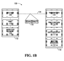
- a network 130 of Figure 1B shows the opposite configuration in which a master device 110 is a pingable device and a peripheral 118 is a pinging device.
- the master device 110 and the peripheral 118 can be the type of electronic devices described in respect to Figure 1A.
- the master device 110 is "paired with" at least the peripheral 118.
- the peripheral 118 contains a master identifier 112 or other means known in the art of identifying the master device 110 to which the peripheral 118 is connected and identifying communications channel 124 to the master device 110.
- the master identifier 112 is generated when the pairing between the master device 110 and the peripheral 118 is established.
- the peripheral 118 includes a ping function 114.
- the ping function 114 may be provided in a manner as described in respect of Figure 1A.
- the ping function 114 is initiated through a user interface 117.
- the master device 110 has a ping message processing function (PMPF) 122.
- the ping message processing function 122 allows the master device 110 to receive and respond to a message from the ping function 114.
- the ping message processing function 122 may be provided as described with respect to Figure 1A.
- the master device 110 has at least one indicator element 120.
- the indicator element 120 generates an indication that is audible, visible, tactile, or otherwise perceptible to the user as described in respect of Figure 1A.
- the master device 110 also includes a receiver 132 for receiving transmissions from the transmitter 115 of the peripheral 118.
- the initiation of the ping function 114 generates a ping control message 116.
- the pinging operation of the network 130 of Figure 1B is similar to the pinging operation of the network 30 of Figure 1A.
- the user initiates the ping function 114 which generates the ping control message 116.
- the ping function 114 instructs the transmitter 115 to send the ping control message 116 over the communication channel 124 to the receiver 132 of the master device 110.
- the ping message processing function 122 receives the ping control message 116 through the receiver 132 and actuates the indicator element 120 in accordance with the instructions contained in the ping control message 116.
- peripherals may be connected to the master device 110 in the network 130.
- FIG. 2 is a flow chart of an example method of the operation of the pinging device of Figures 1A and 1B.
- the user initiates the ping function. This may be achieved using any of the means described above.
- the ping function generates the ping control message based on input received from the user. This may be as simple as generating a standard message based on the pressing of a button by the user or may involve multiple user inputs as described below with respect to Figure 4.
- Step 54 involves sending the ping control message to the at least one pingable device which is in communication with the pinging device over a respective communication channel.
- FIG. 3 is a flowchart of an example method of the operation of the pingable device of Figures 1A and 1B.
- the receiver of the at least one paired pingable device receives the ping control message.
- the ping message processing function actuates one or more indicator elements in accordance with the dictates of the ping control message.
- the ping message processing functions stop the actuation of the indicator elements.
- the instructions for stopping the actuation of the indicator elements may be received by the ping message processing functions as part of the original ping control message or may comprise a second ping control message. In some embodiments, there are no separate instructions for stopping, stopping happening automatically by a timer.
- the user interfaces 17 and 117 may take various forms. In the embodiment described in respect of Figure 1A, all of the network peripherals 18a, 18b, 18c are paged by one ping control message 16. In that embodiment, the user interface 17 may be in the form of a labelled button on the master device 10 which simply needs to be pressed by the user to initiate the ping function 14. Other user interfaces such as voice recognition, stylus input, trackwheel input, clapping or other distinct sounds detected by a microphone, menu items selected by the user in the GUI, sequence of keystrokes (double-clicking, triple-clicking, or clicking a distinct rhythm) may alternatively be used.
- Figures 4A to 4C depict a menu user interface 70.
- the menu user interface 70 consists of a display 80 and buttons (or other user interface elements) 72, 74, 76, 78.
- the button 72 is associated with initiating the ping function.
- the buttons 74, 76, 78 may be associated with other unrelated functions.
- the depression of the button 72 results in the display of the menu shown in Figure 4B.
- the menu of Figure 4B allows the user to select which paired device to ping.
- depressing the button 72 selects the pinging of all paired devices
- depressing the button 74 selects the pinging of a paired headset
- depressing the button 76 selects the pinging of a paired printer
- depressing the button 78 selects the pinging of a paired PDA.
- the display 80 may list any number and combination of paired devices.
- buttons 72, 74, 76, 78 results in the display of the menu shown in Figure 4C.
- the menu of Figure 4C allows the user to select which indicator elements of the paired devices to actuate.
- depressing the button 72 selects the actuation of all indicator elements
- depressing the button 74 selects the actuation of audible indicator elements
- depressing the button 76 selects the actuation of visible indicator elements
- depressing the button 78 selects the actuation of tactile indicator elements.
- the display 80 may allow the actuation of any combination of indicator elements.
- the menu user interface 70 provides the ping function 14 with the flexibility to allow the user to ping all of the paired devices or to ping only one or a specific combination of the paired devices.
- Alternative menu structures which allow for other selection options are also contemplated by this application as well as other forms of user interfaces such as touch screens.
- the ping function 14 may allow the user to specify in the ping control message 16 the duration for which the indicator elements 20a, 20b, 20c are actuated.
- the ping function 14 may provide instructions in the ping control message 16 to actuate the indicator element 20a, 20b, 20c for a specified length of time or to continue to actuate the indicator elements 20a, 20b, 20c until the ping function 14 is deactivated.
- These various options can all be provided through the menu user interface.
- the options can alternatively be offered remotely, through radio or quantum communication, artificial intelligence, or fuzzy logic.
Abstract
Description
- This application is related to wireless radio frequency communication networks, and more particularly, to a system and method for identifying and locating electronic devices in the network.
- Electronic devices can be interconnected by a variety of means including wires, cables, radio signals and infrared light beams. Wireless communication such as infrared light beams and radio signals have become increasingly popular communication means, particularly in the field of consumer electronics. With the increasing number of electronic devices available, consumers want their electronic devices to be able to communicate with each other, even if the manufacturers differ. The Bluetooth standard has been developed to allow electronic devices produced by different manufacturers to communicate with each other using ad hoc wireless communication links, established between pairs of devices, one of the devices typically being a peripheral such as a handset or a printer.
- In response to a consumer demand for simplification, the Bluetooth standard (see "Specification of the Bluetooth System: Wireless Connections Made Easy", Version 1.2 (5 November 2003) http:/www.Bluetooth.com) allows electronic devices to establish communications with minimal need for input from the user.
- According to a broad aspect, there is provided a pinging electronic device comprising a ping function and a transmitter wherein the ping function is adapted to generate and the transmitter is adapted to transmit over an ad hoc wireless network at least one associated ping control message to at least one pingable electronic device paired to the pinging electronic device for actuation of at least one indicator element of the at least one pingable electronic device.
- In some embodiments, the pinging electronic device is a master device. In other embodiments, the pinging electronic device is a peripheral device.
- According to a further broad aspect, the invention provides a pingable electronic device comprising a receiver, a ping message processor, and at least one indicator element wherein the receiver is adapted to receive a ping control over an ad hoc wireless network message and the ping message processor is adapted to actuate the at least one indicator element in response to the ping control message.
- In some embodiments, an ad hoc wireless network including a plurality of pingable electronic devices further comprises a pinging electronic device comprising a ping function and a transmitter wherein the pinging electronic device is paired to the plurality of pingable electronic devices and wherein the ping function is adapted to generate and the transmitter is adapted to transmit over an ad hoc wireless network the ping control message to the plurality of pingable electronic devices.
- In some embodiments, the ping function is adapted to ping all of the plurality of pingable electronic devices.
- In some embodiments, the ping function is adapted to ping a subset of the plurality of pingable electronic devices based on a user selection.
- In some embodiments, the ping control message contains instructions which define which of the at least one indicator elements are actuated.
- In some embodiments, the ping control message sent to each of the at least one pingable electronic devices is identical.
- In some embodiments, the ping control message sent to each of the at least one pingable electronic devices is unique.
- In some embodiments, the ad hoc wireless network is a Bluetooth capable network or a Bluetooth like network.
- In some embodiments, the ping message processor of each of the at least one pingable electronic devices is adapted to decode whether the ping control message contains instructions to ping the pingable electronic device.
- According to one broad aspect, the invention provides a computer usable medium having computer readable program code means embodied therein for causing a ping message to be sent over an ad hoc wireless network, the computer readable code means comprising: a computer readable code means for processing a received ping input command; a computer readable code means for generating a ping message; a computer readable code means for instructing a transmitter to transmit the ping message.
- In some embodiments, the computer readable code means for generating a ping message further comprises a computer readable code means for generating the ping message for pinging a plurality of pingable electronic devices.
- In some embodiments, the computer readable code means for generating a ping message further comprises: a computer readable code means for generating the ping message for pinging a subset of a plurality of pingable electronic devices based on a user selection.
- In some embodiments, the computer readable code means for generating a ping message further comprises: a computer readable code means for generating a ping control message containing instructions which specify which indicator elements are actuated.
- According to one broad aspect, the invention provides a computer usable medium having computer readable program code means embodied therein for receiving and implementing a ping message from an ad hoc wireless network, the computer readable code means comprising; a computer readable code means for processing a received ping message; a computer readable code means for instructing a indicator element in response to the ping message.
-
- Figure 1A is a schematic view of an embodiment of a wireless communication network;
- Figure 1B is a schematic view of another embodiment of a wireless communication network;
- Figure 2 is a flow diagram of the operation of a pinging device in the wireless communication network of Figure 1A or Figure 1B;
- Figure 3 is a flow diagram of the operation of a pingable device in the wireless communication network of Figure 1A or Figure 1B;
- Figures 4A to 4C are schematic diagrams of a user interface for the pinging device in the wireless communication network of Figure 1A or Figure 1B.
- Figure 1A shows an ad hoc
wireless network 30 provided by an embodiment of the application. Thenetwork 30 is comprised of amaster device 10, such as a telephone handset, PDA, computer or other such electronic device. - Network 30 also comprises a plurality of
network peripherals network 30 at the instant depicted in Figure 1A. - In the embodiment of Figure 1A, the
master device 10 is in communication with or "paired with"network peripherals communication channels master device 10 includes atransmitter 15 for transmitting to thenetwork peripherals transmitter 15 may take any form known in the art including being a combined transceiver. - The
master device 10 contains a list ofperipherals 12 or other means of identifying thenetwork peripherals master device 10 is connected and identifyingcommunications channels network peripherals peripherals 12 is typically easily accessible to the user. The list ofperipherals 12 is first generated when thenetwork 30 is set up and the pairing between themaster device 10 and thenetwork peripherals peripherals 12 is dynamic; it can change over time as peripherals are added to or deleted from thenetwork 30. - If the
network 30 is established according to the Bluetooth standard, no user input is required to establish thenetwork 30 so the user may be unaware of the pairings which have been established in thenetwork 30. Alternatively, even if the user is initially aware of the pairings, if time has elapsed since thenetwork 30 was initially established, the pairings which were made may have been forgotten or the user may have misplaced one or more of thenetwork peripherals peripherals master device 10 and of identifying the location of thenetwork peripherals - The
master device 10, therefore, includes aping function 14. Theping function 14 may be provided in software, hardware, firmware or other means known in the art. Theping function 14 is initiated through a user interface 17. - The
peripherals peripherals ping function 14. The pingmessage processing functions - Each of the
peripherals indicator element indicator elements - The indicator elements may, to some extent, be determined by the type of
peripherals indicator elements peripherals peripherals indicator elements - The
peripherals receivers transmitter 15 of themaster device 10. Thereceivers - The initiation of the
ping function 14 generates aping control message 16 which contains instructions for the pingmessage processing function ping control message 16 will be dictated by the communication protocol of thecommunication channels network 30. In some embodiments, a single message is transmitted by thetransmitter 15, and the message is received and processed by each peripheral that is paired. In another embodiment, a separate message is transmitted to each peripheral. The separate message may be identical, or they may be different for each peripheral. For example, in one embodiment, each message contains a peripheral-specific destination address. Theping control message 16 depicted in Figure 1A is a single message containing source and length, which is sent to all the pairedperipherals - In operation, the user initiates the
ping function 14 which generates theping control message 16. Theping function 14 instructs thetransmitter 15 to send theping control message 16 over thecommunication channels receivers network peripherals master device 10. The isolated peripheral 19 is not paired with themaster device 10. Accordingly, theping control message 16 is not sent to the isolated peripheral 19. - The ping message processing functions 22a, 22b, 22c receive the
ping control message 16 through thereceivers indicator elements ping control message 16. - The
indicator elements 21 of the isolated peripheral 19 are not actuated. The user can then easily locate thenetwork peripherals indicator elements master device 10 is a telephone handset, network peripheral 18a and the isolated peripheral 19 are telephone headsets, and theindicator elements - In another embodiment, a plant manufacturing Bluetooth electronic devices requires quality control testing to determine if an electronic device under test is correctly paired with a chosen master device. It is cumbersome and slow to check for the correct pairing by using the machine address in the generic user interface of the electronic device to conduct the test. Instead, the ping method described above is used to conduct quality control testing. In order to pass the quality control test, an operator tests each electronic device that comes off of the line by pairing it to a reference PDA and pinging the PDA to ensure that the paired device is the electronic device currently in the operator's hand and not an electronic device from the adjacent assembly line.
- Although three
network peripherals network 30 is a dynamic network and any number of network peripherals allowed by the network specification may be present in thenetwork 30 at different points in time. - It is preferred that all of the
peripherals peripherals - Preferably, the
network 30 of Figure 1A is established using Bluetooth or Bluetooth-like technology. In a Bluetooth network, thenetwork peripherals master device 10. While thenetwork peripherals master device 10, thecommunication channels network peripherals master device 10. If an event is received from themaster device 10 which is destined to one of thenetwork peripherals - In the Bluetooth specification, each of the
network peripherals 18b 18c can theoretically see all of the communications from allnearby network peripherals 18b 18c; however, in practice, most Bluetooth communications are encrypted. As well, the Bluetooth specification requires that each electronic device in thenetwork 30 only be active on certain frequencies during window periods determined by a frequency-hopping algorithm (see page 316 in the pdf of the Bluetooth 1.2 specification). Thus, in the Bluetooth application, eachnetwork peripherals own communication channels - Although Figure 1A depicts one
message 16 broadcast to all of the pairednetwork peripherals message processing function - If the
network 30 is established according to the Bluetooth standard, the form of theping control message 16 can be implemented in various ways. Depending on which protocol is used to adapt the functionality, the code used to identify the ping feature will vary. - In one embodiment, if the ping function were made a part of the Bluetooth HCI protocol, it could be defined as:
-
OpCode Octet 16, bit 6 (page 530 in the pdf of the Bluetooth 1.2 specification). - In another embodiment, if the ping function were part of the ICMP Protocol, it could be defined as Type 41, which is currently unused. The code field could be used for the operation code defined below.
(See http://www.iana.org/assignments/icmp-parameters - list of Type codes.) - In other embodiments the ping functionality can be built over User Data Protocol(UDP) specified by RFC 768 (http://www.faqs.org/rfcs/rfc768.html), Transmission Control Protocol (TCP) specified by RFC 793 (http://www.faqs.org/rfcs/rfc793.html) or other transport by defining a format in the payload:
- Payload:
- First 4 bytes indicate operation code:
- 0x00000000 - PING
- 0x00000001 through 0xffffffff - undefined.
- For 0x00000000 - PING:
- Next byte - OPCode parameters as defined below.
- First 4 bytes indicate operation code:
- The opcode parameter information on the other hand can be constant irrespective of the opcode that is defined.
- In one embodiment the following pre-defined payload messages can be used:
- <Value> - <Meaning>
- 0x00 - ping, perform UI notification, no reply
- 0x01 - ping, perform UI notification, send PING reply (PING-back).
- 0x02-0xff - undefined.
- Examples of the implementation of the ping message processing functions 22a, 22b, 22c, 23 are as follows:
- Software case: In an embodiment where the peripheral is a local area network (LAN) interface card Bluetooth peripheral which must be plugged into a personal computer (PC) (via universal serial bus (USB) (http://www.activewin.com/faq/usb.shtml), for instance), the ping event notification can be implemented by posting an event to the host computer where a user interface (UI) message, sound, blinking of an icon, or other mechanism would tell the user that an incoming ping was detected. Firmware case: In another embodiment, instructions to a central processing unit (CPU) for detecting and handling the ping message are stored in flash random access memory (RAM), or other re-writable non-volatile storage medium.
- Hardware case: In a further embodiment instructions to a central processing unit (CPU) for detecting and handling the ping message are stored in a non-volatile storage medium that is not re-writable, such as a silicon microchip.
- The example of
indicator elements ping control message 16 may alternatively be stored in a retrieval system such as a hard disk and reported to the user at a later time. A ping back indicator element can alternatively be used if the peripheral has a transmitter and the master device has a receiver. The indicator element of the peripheral can be a reply to the ping message which is another ping message transmitted back to the master device. - The
network 30 is preferably a Bluetooth network but, more generally, can be any network which is ad-hoc wireless, open to interference between endpoints (i.e. electronic devices), and has the possibility of ambiguity regarding the associations between endpoints. For example, the application may be used in a WI-FI (802.11) network to determine the access point with which a device is currently associated. The application may also be used in a peer-to-peer system where two computers are connected haphazardly. - In the
network 30 of Figure 1A themaster device 10 is the pinging device and theperipherals network 130 of Figure 1B shows the opposite configuration in which amaster device 110 is a pingable device and a peripheral 118 is a pinging device. Themaster device 110 and the peripheral 118 can be the type of electronic devices described in respect to Figure 1A. - The
master device 110 is "paired with" at least the peripheral 118. - The peripheral 118 contains a
master identifier 112 or other means known in the art of identifying themaster device 110 to which the peripheral 118 is connected and identifyingcommunications channel 124 to themaster device 110. Themaster identifier 112 is generated when the pairing between themaster device 110 and the peripheral 118 is established. - The peripheral 118 includes a
ping function 114. Theping function 114 may be provided in a manner as described in respect of Figure 1A. Theping function 114 is initiated through a user interface 117. - The
master device 110 has a ping message processing function (PMPF) 122. The pingmessage processing function 122 allows themaster device 110 to receive and respond to a message from theping function 114. The pingmessage processing function 122 may be provided as described with respect to Figure 1A. - The
master device 110 has at least oneindicator element 120. Theindicator element 120 generates an indication that is audible, visible, tactile, or otherwise perceptible to the user as described in respect of Figure 1A. Themaster device 110 also includes areceiver 132 for receiving transmissions from thetransmitter 115 of the peripheral 118. - The initiation of the
ping function 114 generates aping control message 116. The pinging operation of thenetwork 130 of Figure 1B is similar to the pinging operation of thenetwork 30 of Figure 1A. The user initiates theping function 114 which generates theping control message 116. Theping function 114 instructs thetransmitter 115 to send theping control message 116 over thecommunication channel 124 to thereceiver 132 of themaster device 110. The pingmessage processing function 122 receives theping control message 116 through thereceiver 132 and actuates theindicator element 120 in accordance with the instructions contained in theping control message 116. - It will be understood that additional peripherals may be connected to the
master device 110 in thenetwork 130. - The various embodiments described with respect to the
network 30 of Figure 1A are also applicable to thenetwork 130 of Figure 1B. - Figure 2 is a flow chart of an example method of the operation of the pinging device of Figures 1A and 1B. In
step 50, the user initiates the ping function. This may be achieved using any of the means described above. Instep 52, the ping function generates the ping control message based on input received from the user. This may be as simple as generating a standard message based on the pressing of a button by the user or may involve multiple user inputs as described below with respect to Figure 4.Step 54 involves sending the ping control message to the at least one pingable device which is in communication with the pinging device over a respective communication channel. - Figure 3 is a flowchart of an example method of the operation of the pingable device of Figures 1A and 1B. In
step 60, the receiver of the at least one paired pingable device receives the ping control message. Instep 62, the ping message processing function actuates one or more indicator elements in accordance with the dictates of the ping control message. Instep 64, the ping message processing functions stop the actuation of the indicator elements. The instructions for stopping the actuation of the indicator elements may be received by the ping message processing functions as part of the original ping control message or may comprise a second ping control message. In some embodiments, there are no separate instructions for stopping, stopping happening automatically by a timer. - The user interfaces 17 and 117 may take various forms. In the embodiment described in respect of Figure 1A, all of the
network peripherals ping control message 16. In that embodiment, the user interface 17 may be in the form of a labelled button on themaster device 10 which simply needs to be pressed by the user to initiate theping function 14. Other user interfaces such as voice recognition, stylus input, trackwheel input, clapping or other distinct sounds detected by a microphone, menu items selected by the user in the GUI, sequence of keystrokes (double-clicking, triple-clicking, or clicking a distinct rhythm) may alternatively be used. - Figures 4A to 4C depict a
menu user interface 70. Themenu user interface 70 consists of adisplay 80 and buttons (or other user interface elements) 72, 74, 76, 78. Initially, as shown in Figure 4A, thebutton 72 is associated with initiating the ping function. Thebuttons button 72 results in the display of the menu shown in Figure 4B. The menu of Figure 4B allows the user to select which paired device to ping. In particular, depressing thebutton 72 selects the pinging of all paired devices, depressing thebutton 74 selects the pinging of a paired headset, depressing thebutton 76 selects the pinging of a paired printer, and depressing thebutton 78 selects the pinging of a paired PDA. More generally, thedisplay 80 may list any number and combination of paired devices. - The depression of any one of the
buttons button 72 selects the actuation of all indicator elements, depressing thebutton 74 selects the actuation of audible indicator elements, depressing thebutton 76 selects the actuation of visible indicator elements, and depressing thebutton 78 selects the actuation of tactile indicator elements. More generally, thedisplay 80 may allow the actuation of any combination of indicator elements. - The
menu user interface 70 provides theping function 14 with the flexibility to allow the user to ping all of the paired devices or to ping only one or a specific combination of the paired devices. Alternative menu structures which allow for other selection options are also contemplated by this application as well as other forms of user interfaces such as touch screens. - The
ping function 14 may allow the user to specify in theping control message 16 the duration for which theindicator elements - Alternatively, the
ping function 14 may provide instructions in theping control message 16 to actuate theindicator element indicator elements ping function 14 is deactivated. These various options can all be provided through the menu user interface. The options can alternatively be offered remotely, through radio or quantum communication, artificial intelligence, or fuzzy logic. - References to computers in this specification include quantum computers.
- The above description of embodiments should not be interpreted in any limiting manner since variations and refinements can be made without departing from the scope of the application.
Claims (27)
- A pinging electronic device comprising a ping function and a transmitter wherein the ping function is adapted to generate and the transmitter is adapted to transmit over an ad hoc wireless network at least one associated ping control message to at least one pingable electronic device paired to the pinging electronic device for actuation of at least one indicator element of the at least one pingable electronic device.
- The pinging electronic device according to claim 1 wherein the at least one pingable electronic device comprises a plurality of pingable electronic devices and the ping function is adapted to ping all of the plurality of pingable electronic devices.
- The pinging electronic device according to claim 1 wherein the at least one pingable electronic device comprises a plurality of pingable electronic devices and the ping function is adapted to ping a subset of the plurality of pingable electronic devices based on a user selection.
- The pinging electronic device according to any one of claims 1 to 3 wherein the ping control message contains instructions which define which of the at least one indicator elements are actuated.
- The pinging electronic device according to any one of claims 1 to 4 wherein the ping control message sent to each of the at least one pingable electronic devices is identical.
- The pinging electronic device according to any one of claims 1 to 4 wherein the ping control message sent to each of the at least one pingable electronic devices is unique.
- The pinging electronic device according to any one of claims 1 to 6 wherein the ad hoc wireless network is a Bluetooth capable network or Bluetooth like network.
- The pinging electronic device according to any one of claims 1 to 7 wherein the pinging electronic device is a master device.
- The pinging electronic device according to any one of claims 1 to 7 wherein the pinging electronic device is a peripheral device.
- A pingable electronic device comprising a receiver, a ping message processor, and at least one indicator element wherein the receiver is adapted to receive a ping control message over an ad hoc wireless network and the ping message processor is adapted to actuate the at least one indicator element in response to the ping control message.
- The pingable electronic device according to claim 10 wherein the ping message processor is adapted to decode whether the ping control message contains instructions to ping the pingable electronic device.
- The pingable electronic device according to claim 10 or 11 wherein the ping control message contains instructions which determine which of the at least one indicator elements are actuated.
- The pingable electronic device according to any one of claims 10 to 12 wherein the pingable electronic device is a Bluetooth capable device or a Bluetooth like device.
- An ad hoc wireless network including a plurality of pingable electronic devices according to claim 10 and a pinging electronic device comprising a ping function and a transmitter wherein the pinging electronic device is paired to the plurality of pingable electronic devices and wherein the ping function is adapted to generate and the transmitter is adapted to transmit over the ad hoc wireless network the ping control message to the plurality of pingable electronic devices.
- The ad hoc wireless network according to claim 14 wherein the ping function is adapted to ping all of the plurality of pingable electronic devices.
- The ad hoc wireless network according to claim 14 wherein the ping function is adapted to ping a subset of the plurality of pingable electronic devices based on a user selection.
- The ad hoc wireless network according to any one of claims 14 to 16 wherein the ping control message contains instructions which define which of the at least one indicator elements are actuated.
- The ad hoc wireless network according to any one of claims 14 to 17 wherein the ping control message sent to each of the plurality of pingable electronic devices is identical.
- The ad hoc wireless network according to any one of claims 14 to 17 wherein the ping control message sent to each of the plurality of pingable electronic devices is unique.
- The ad hoc wireless network according to any one of claims 14 to 19 wherein the wireless communication network is a Bluetooth capable network or a Bluetooth like network.
- The ad hoc wireless network according to claim 18 wherein the ping message processor of each of the plurality of pingable electronic devices is adapted to decode whether the ping control message contains instructions to ping the pingable electronic device.
- A computer usable medium having computer readable program code means embodied therein for causing a ping message to be sent over an ad hoc wireless network, the computer readable code means comprising:a computer readable code means for processing a received ping input command;a computer readable code means for generating a ping message;a computer readable code means for instructing a transmitter to transmit the ping message.
- The computer readable code means according to claim 22 wherein the computer readable code means for generating a ping message further comprising:a computer readable code means for generating the ping message for pinging a plurality of pingable electronic devices.
- The computer readable code means according to claim 22 wherein the computer readable code means for generating a ping message further comprising:a computer readable code means for generating the ping message for pinging a subset of a plurality of pingable electronic devices based on a user selection.
- The computer readable code means according to any one of claims 22 to 24 wherein the computer readable code means for generating a ping message further comprising:a computer readable code means for generating a ping control message containing instructions which specify which indicator elements are actuated.
- The computer readable code means according to any one of claims 22 to 25 for use in a Bluetooth capable network or a Bluetooth like network.
- A computer usable medium having computer readable program code means embodied therein, the computer readable code means comprising;
a computer readable code means for processing a ping message received from an ad hoc wireless network; and
a computer readable code means for instructing an indicator element to actuate in response to the ping message.
Priority Applications (9)
| Application Number | Priority Date | Filing Date | Title |
|---|---|---|---|
| DE602004013813T DE602004013813D1 (en) | 2004-12-23 | 2004-12-23 | Ping functionality for electronic devices |
| EP04106973A EP1675314B1 (en) | 2004-12-23 | 2004-12-23 | Ping Feature for Electronic Devices |
| AT04106973T ATE395769T1 (en) | 2004-12-23 | 2004-12-23 | PING FUNCTIONALITY FOR ELECTRONIC DEVICES |
| US11/020,318 US7869762B2 (en) | 2004-12-23 | 2004-12-27 | Ping feature for electronic devices |
| SG200508083A SG123720A1 (en) | 2004-12-23 | 2005-12-13 | Ping feature for electronic devices |
| CA002531371A CA2531371C (en) | 2004-12-23 | 2005-12-22 | Ping feature for electronic devices |
| CNA2005101381143A CN1794664A (en) | 2004-12-23 | 2005-12-22 | Ping feature for electronic devices |
| US12/973,288 US8185051B2 (en) | 2004-12-23 | 2010-12-20 | Ping feature for electronic devices |
| US13/453,428 US8583084B2 (en) | 2004-12-23 | 2012-04-23 | Ping feature for electronic devices |
Applications Claiming Priority (1)
| Application Number | Priority Date | Filing Date | Title |
|---|---|---|---|
| EP04106973A EP1675314B1 (en) | 2004-12-23 | 2004-12-23 | Ping Feature for Electronic Devices |
Publications (2)
| Publication Number | Publication Date |
|---|---|
| EP1675314A1 true EP1675314A1 (en) | 2006-06-28 |
| EP1675314B1 EP1675314B1 (en) | 2008-05-14 |
Family
ID=34930164
Family Applications (1)
| Application Number | Title | Priority Date | Filing Date |
|---|---|---|---|
| EP04106973A Active EP1675314B1 (en) | 2004-12-23 | 2004-12-23 | Ping Feature for Electronic Devices |
Country Status (7)
| Country | Link |
|---|---|
| US (3) | US7869762B2 (en) |
| EP (1) | EP1675314B1 (en) |
| CN (1) | CN1794664A (en) |
| AT (1) | ATE395769T1 (en) |
| CA (1) | CA2531371C (en) |
| DE (1) | DE602004013813D1 (en) |
| SG (1) | SG123720A1 (en) |
Families Citing this family (50)
| Publication number | Priority date | Publication date | Assignee | Title |
|---|---|---|---|---|
| AU2003209194A1 (en) | 2002-01-08 | 2003-07-24 | Seven Networks, Inc. | Secure transport for mobile communication network |
| US7917468B2 (en) | 2005-08-01 | 2011-03-29 | Seven Networks, Inc. | Linking of personal information management data |
| US8140013B1 (en) | 2003-06-04 | 2012-03-20 | Cypress Semiconductor Corporation | Wireless communication device and method |
| US7848703B1 (en) * | 2004-12-30 | 2010-12-07 | Cypress Semiconductor Corporation | Method and apparatus for binding wireless devices |
| US20060195695A1 (en) * | 2005-02-25 | 2006-08-31 | John Keys | Techniques for verification of electronic device pairing |
| US8438633B1 (en) | 2005-04-21 | 2013-05-07 | Seven Networks, Inc. | Flexible real-time inbox access |
| WO2006136660A1 (en) | 2005-06-21 | 2006-12-28 | Seven Networks International Oy | Maintaining an ip connection in a mobile network |
| WO2007055623A1 (en) * | 2005-11-11 | 2007-05-18 | Telefonaktiebolaget L M Ericsson (Publ) | Method and apparatus for limiting peer-to-peer communication interference |
| US7769395B2 (en) | 2006-06-20 | 2010-08-03 | Seven Networks, Inc. | Location-based operations and messaging |
| US20080170508A1 (en) * | 2007-01-17 | 2008-07-17 | Abb Technology Ag | Channel integrity metric calculation |
| US8805425B2 (en) | 2007-06-01 | 2014-08-12 | Seven Networks, Inc. | Integrated messaging |
| US8364181B2 (en) | 2007-12-10 | 2013-01-29 | Seven Networks, Inc. | Electronic-mail filtering for mobile devices |
| US9002828B2 (en) | 2007-12-13 | 2015-04-07 | Seven Networks, Inc. | Predictive content delivery |
| US8862657B2 (en) | 2008-01-25 | 2014-10-14 | Seven Networks, Inc. | Policy based content service |
| US20090193338A1 (en) * | 2008-01-28 | 2009-07-30 | Trevor Fiatal | Reducing network and battery consumption during content delivery and playback |
| US8787947B2 (en) | 2008-06-18 | 2014-07-22 | Seven Networks, Inc. | Application discovery on mobile devices |
| US8078158B2 (en) | 2008-06-26 | 2011-12-13 | Seven Networks, Inc. | Provisioning applications for a mobile device |
| US8909759B2 (en) | 2008-10-10 | 2014-12-09 | Seven Networks, Inc. | Bandwidth measurement |
| CN101964671A (en) * | 2009-07-22 | 2011-02-02 | 鸿富锦精密工业(深圳)有限公司 | Automatic testing method for Bluetooth function of electronic product |
| US8838783B2 (en) | 2010-07-26 | 2014-09-16 | Seven Networks, Inc. | Distributed caching for resource and mobile network traffic management |
| EP3651028A1 (en) | 2010-07-26 | 2020-05-13 | Seven Networks, LLC | Mobile network traffic coordination across multiple applications |
| US8903954B2 (en) | 2010-11-22 | 2014-12-02 | Seven Networks, Inc. | Optimization of resource polling intervals to satisfy mobile device requests |
| US8484314B2 (en) | 2010-11-01 | 2013-07-09 | Seven Networks, Inc. | Distributed caching in a wireless network of content delivered for a mobile application over a long-held request |
| WO2012060995A2 (en) | 2010-11-01 | 2012-05-10 | Michael Luna | Distributed caching in a wireless network of content delivered for a mobile application over a long-held request |
| US8843153B2 (en) | 2010-11-01 | 2014-09-23 | Seven Networks, Inc. | Mobile traffic categorization and policy for network use optimization while preserving user experience |
| GB2501416B (en) | 2011-01-07 | 2018-03-21 | Seven Networks Llc | System and method for reduction of mobile network traffic used for domain name system (DNS) queries |
| US8316098B2 (en) | 2011-04-19 | 2012-11-20 | Seven Networks Inc. | Social caching for device resource sharing and management |
| EP2702500B1 (en) | 2011-04-27 | 2017-07-19 | Seven Networks, LLC | Detecting and preserving state for satisfying application requests in a distributed proxy and cache system |
| EP2621144B1 (en) | 2011-04-27 | 2014-06-25 | Seven Networks, Inc. | System and method for making requests on behalf of a mobile device based on atomic processes for mobile network traffic relief |
| WO2013015995A1 (en) | 2011-07-27 | 2013-01-31 | Seven Networks, Inc. | Automatic generation and distribution of policy information regarding malicious mobile traffic in a wireless network |
| US8868753B2 (en) | 2011-12-06 | 2014-10-21 | Seven Networks, Inc. | System of redundantly clustered machines to provide failover mechanisms for mobile traffic management and network resource conservation |
| US8934414B2 (en) | 2011-12-06 | 2015-01-13 | Seven Networks, Inc. | Cellular or WiFi mobile traffic optimization based on public or private network destination |
| US9277443B2 (en) | 2011-12-07 | 2016-03-01 | Seven Networks, Llc | Radio-awareness of mobile device for sending server-side control signals using a wireless network optimized transport protocol |
| WO2013086455A1 (en) | 2011-12-07 | 2013-06-13 | Seven Networks, Inc. | Flexible and dynamic integration schemas of a traffic management system with various network operators for network traffic alleviation |
| EP2792188B1 (en) | 2011-12-14 | 2019-03-20 | Seven Networks, LLC | Mobile network reporting and usage analytics system and method using aggregation of data in a distributed traffic optimization system |
| WO2013103988A1 (en) | 2012-01-05 | 2013-07-11 | Seven Networks, Inc. | Detection and management of user interactions with foreground applications on a mobile device in distributed caching |
| WO2013116856A1 (en) | 2012-02-02 | 2013-08-08 | Seven Networks, Inc. | Dynamic categorization of applications for network access in a mobile network |
| WO2013116852A1 (en) | 2012-02-03 | 2013-08-08 | Seven Networks, Inc. | User as an end point for profiling and optimizing the delivery of content and data in a wireless network |
| US8812695B2 (en) | 2012-04-09 | 2014-08-19 | Seven Networks, Inc. | Method and system for management of a virtual network connection without heartbeat messages |
| WO2013155208A1 (en) | 2012-04-10 | 2013-10-17 | Seven Networks, Inc. | Intelligent customer service/call center services enhanced using real-time and historical mobile application and traffic-related statistics collected by a distributed caching system in a mobile network |
| WO2014011216A1 (en) | 2012-07-13 | 2014-01-16 | Seven Networks, Inc. | Dynamic bandwidth adjustment for browsing or streaming activity in a wireless network based on prediction of user behavior when interacting with mobile applications |
| US9161258B2 (en) | 2012-10-24 | 2015-10-13 | Seven Networks, Llc | Optimized and selective management of policy deployment to mobile clients in a congested network to prevent further aggravation of network congestion |
| US9767066B2 (en) * | 2012-12-11 | 2017-09-19 | Mark Kramer | Wireless protocol communication bridge and system comprising bridge |
| US9307493B2 (en) | 2012-12-20 | 2016-04-05 | Seven Networks, Llc | Systems and methods for application management of mobile device radio state promotion and demotion |
| US9241314B2 (en) | 2013-01-23 | 2016-01-19 | Seven Networks, Llc | Mobile device with application or context aware fast dormancy |
| US8874761B2 (en) | 2013-01-25 | 2014-10-28 | Seven Networks, Inc. | Signaling optimization in a wireless network for traffic utilizing proprietary and non-proprietary protocols |
| US9326185B2 (en) | 2013-03-11 | 2016-04-26 | Seven Networks, Llc | Mobile network congestion recognition for optimization of mobile traffic |
| US9065765B2 (en) | 2013-07-22 | 2015-06-23 | Seven Networks, Inc. | Proxy server associated with a mobile carrier for enhancing mobile traffic management in a mobile network |
| US10680731B2 (en) | 2015-09-05 | 2020-06-09 | The Nielsen Company (Us), Llc | Methods and apparatus to facilitate local time-based digital audio measurement |
| US20200067760A1 (en) * | 2018-08-21 | 2020-02-27 | Vocollect, Inc. | Methods, systems, and apparatuses for identifying connected electronic devices |
Citations (5)
| Publication number | Priority date | Publication date | Assignee | Title |
|---|---|---|---|---|
| US6297737B1 (en) * | 2000-04-03 | 2001-10-02 | Ericsson Inc | Object locating system |
| US20020014955A1 (en) * | 1999-11-15 | 2002-02-07 | Klitsgaard Niels Christian | Object detection system |
| US20020081970A1 (en) * | 2000-12-21 | 2002-06-27 | Gustav Wingren | Method and system for locating a device using a local wireless link |
| US20020101343A1 (en) * | 2001-01-29 | 2002-08-01 | Patton David B. | Apparatus and method for selecting wireless devices |
| WO2003058572A1 (en) * | 2001-12-19 | 2003-07-17 | Peter Sandberg | Location unit |
Family Cites Families (6)
| Publication number | Priority date | Publication date | Assignee | Title |
|---|---|---|---|---|
| US5606560A (en) * | 1994-09-23 | 1997-02-25 | Motorola, Inc. | Between a base station and a portable device |
| US6087933A (en) * | 1996-05-20 | 2000-07-11 | Pittway Corporation | Antenna switching for amplitude degradation during supervision and installation of wireless security systems |
| US5903844A (en) * | 1997-02-04 | 1999-05-11 | Motorola, Inc. | Method and apparatus for determining remote unit location in a communication system |
| US6269257B1 (en) * | 1999-01-21 | 2001-07-31 | Agere Systems Guardian Corp. | Adaptive paging signal in cordless telephone |
| US8068610B2 (en) * | 2001-11-21 | 2011-11-29 | General Instrument Corporation | Method and system for providing security within multiple set-top boxes assigned for a single customer |
| US7433649B2 (en) * | 2004-09-10 | 2008-10-07 | Motorola, Inc. | Tag for facilitating interaction with a wireless communication device |
-
2004
- 2004-12-23 EP EP04106973A patent/EP1675314B1/en active Active
- 2004-12-23 DE DE602004013813T patent/DE602004013813D1/en active Active
- 2004-12-23 AT AT04106973T patent/ATE395769T1/en not_active IP Right Cessation
- 2004-12-27 US US11/020,318 patent/US7869762B2/en active Active
-
2005
- 2005-12-13 SG SG200508083A patent/SG123720A1/en unknown
- 2005-12-22 CA CA002531371A patent/CA2531371C/en active Active
- 2005-12-22 CN CNA2005101381143A patent/CN1794664A/en active Pending
-
2010
- 2010-12-20 US US12/973,288 patent/US8185051B2/en active Active
-
2012
- 2012-04-23 US US13/453,428 patent/US8583084B2/en active Active
Patent Citations (5)
| Publication number | Priority date | Publication date | Assignee | Title |
|---|---|---|---|---|
| US20020014955A1 (en) * | 1999-11-15 | 2002-02-07 | Klitsgaard Niels Christian | Object detection system |
| US6297737B1 (en) * | 2000-04-03 | 2001-10-02 | Ericsson Inc | Object locating system |
| US20020081970A1 (en) * | 2000-12-21 | 2002-06-27 | Gustav Wingren | Method and system for locating a device using a local wireless link |
| US20020101343A1 (en) * | 2001-01-29 | 2002-08-01 | Patton David B. | Apparatus and method for selecting wireless devices |
| WO2003058572A1 (en) * | 2001-12-19 | 2003-07-17 | Peter Sandberg | Location unit |
Also Published As
| Publication number | Publication date |
|---|---|
| US20120203902A1 (en) | 2012-08-09 |
| CA2531371C (en) | 2009-11-10 |
| CN1794664A (en) | 2006-06-28 |
| US20060234630A1 (en) | 2006-10-19 |
| US20110281521A1 (en) | 2011-11-17 |
| ATE395769T1 (en) | 2008-05-15 |
| EP1675314B1 (en) | 2008-05-14 |
| US8583084B2 (en) | 2013-11-12 |
| US7869762B2 (en) | 2011-01-11 |
| US8185051B2 (en) | 2012-05-22 |
| SG123720A1 (en) | 2006-07-26 |
| CA2531371A1 (en) | 2006-06-23 |
| DE602004013813D1 (en) | 2008-06-26 |
Similar Documents
| Publication | Publication Date | Title |
|---|---|---|
| EP1675314B1 (en) | Ping Feature for Electronic Devices | |
| US20140256260A1 (en) | Wireless Device Pairing | |
| US7940732B2 (en) | Automatic wireless network device configuration | |
| JP3790186B2 (en) | Device hiding | |
| US8493946B2 (en) | Identifying a desired mesh network in a multiple network environment | |
| EP1324550B1 (en) | Portable terminal with combined direct short haul radio and cellular radio communication | |
| AU2007243106B2 (en) | Method and system for unambiguous accessory association | |
| EP2163125B1 (en) | Hearing system and method for operating the same | |
| US20120106396A1 (en) | Communication apparatus, communication apparatus control method, and program | |
| CA2875286A1 (en) | Systems and methods for wirelessly modifying detection characteristics of portable devices | |
| WO2011150101A1 (en) | Method for generating audible location alarm from ear level device | |
| CN111447602B (en) | Bluetooth device, Bluetooth preemption method and device thereof, and computer-readable storage medium | |
| EP3288302B1 (en) | System and method for identifying wireless devices for correct pairing | |
| EP3917273B1 (en) | Electronic device for transmitting response message in bluetooth network environment and method therefor | |
| CN104955168A (en) | Audio data transmitting method, receiving method and device | |
| JP2003188886A (en) | Radio communication device, radio communication method, and storage medium | |
| CN104113620A (en) | Contact list updating method, updating device and user terminal | |
| KR20210080897A (en) | Electronic device for transmitting data in bluetooth network environment and method thereof | |
| CN106503023A (en) | The method and device of prompting nearby friends | |
| JP4383700B2 (en) | Mobile communication terminal | |
| JP3943933B2 (en) | Mobile communication terminal | |
| JP5822532B2 (en) | Communication device, control method, and program | |
| Pesavento et al. | Automatic audio routing for home entertainment | |
| US20120191823A1 (en) | Software-Implemented Communications Adapter | |
| JP2014131274A (en) | Hearing device with power management and associated method |
Legal Events
| Date | Code | Title | Description |
|---|---|---|---|
| PUAI | Public reference made under article 153(3) epc to a published international application that has entered the european phase |
Free format text: ORIGINAL CODE: 0009012 |
|
| 17P | Request for examination filed |
Effective date: 20050113 |
|
| AK | Designated contracting states |
Kind code of ref document: A1 Designated state(s): AT BE BG CH CY CZ DE DK EE ES FI FR GB GR HU IE IS IT LI LT LU MC NL PL PT RO SE SI SK TR |
|
| AX | Request for extension of the european patent |
Extension state: AL BA HR LV MK YU |
|
| 17Q | First examination report despatched |
Effective date: 20051104 |
|
| REG | Reference to a national code |
Ref country code: HK Ref legal event code: DE Ref document number: 1089592 Country of ref document: HK |
|
| AKX | Designation fees paid |
Designated state(s): AT BE BG CH CY CZ DE DK EE ES FI FR GB GR HU IE IS IT LI LT LU MC NL PL PT RO SE SI SK TR |
|
| AXX | Extension fees paid |
Extension state: MK Payment date: 20050113 Extension state: YU Payment date: 20050113 Extension state: HR Payment date: 20050113 Extension state: BA Payment date: 20050113 Extension state: AL Payment date: 20050113 Extension state: LV Payment date: 20050113 |
|
| GRAP | Despatch of communication of intention to grant a patent |
Free format text: ORIGINAL CODE: EPIDOSNIGR1 |
|
| GRAS | Grant fee paid |
Free format text: ORIGINAL CODE: EPIDOSNIGR3 |
|
| GRAA | (expected) grant |
Free format text: ORIGINAL CODE: 0009210 |
|
| AK | Designated contracting states |
Kind code of ref document: B1 Designated state(s): AT BE BG CH CY CZ DE DK EE ES FI FR GB GR HU IE IS IT LI LT LU MC NL PL PT RO SE SI SK TR |
|
| AX | Request for extension of the european patent |
Extension state: AL BA HR LV MK YU |
|
| REG | Reference to a national code |
Ref country code: GB Ref legal event code: FG4D |
|
| REG | Reference to a national code |
Ref country code: CH Ref legal event code: EP |
|
| REG | Reference to a national code |
Ref country code: IE Ref legal event code: FG4D Free format text: LANGUAGE OF EP DOCUMENT: FRENCH |
|
| REF | Corresponds to: |
Ref document number: 602004013813 Country of ref document: DE Date of ref document: 20080626 Kind code of ref document: P |
|
| PG25 | Lapsed in a contracting state [announced via postgrant information from national office to epo] |
Ref country code: SI Free format text: LAPSE BECAUSE OF FAILURE TO SUBMIT A TRANSLATION OF THE DESCRIPTION OR TO PAY THE FEE WITHIN THE PRESCRIBED TIME-LIMIT Effective date: 20080514 |
|
| PG25 | Lapsed in a contracting state [announced via postgrant information from national office to epo] |
Ref country code: FI Free format text: LAPSE BECAUSE OF FAILURE TO SUBMIT A TRANSLATION OF THE DESCRIPTION OR TO PAY THE FEE WITHIN THE PRESCRIBED TIME-LIMIT Effective date: 20080514 Ref country code: ES Free format text: LAPSE BECAUSE OF FAILURE TO SUBMIT A TRANSLATION OF THE DESCRIPTION OR TO PAY THE FEE WITHIN THE PRESCRIBED TIME-LIMIT Effective date: 20080825 |
|
| NLV1 | Nl: lapsed or annulled due to failure to fulfill the requirements of art. 29p and 29m of the patents act | ||
| PG25 | Lapsed in a contracting state [announced via postgrant information from national office to epo] |
Ref country code: AT Free format text: LAPSE BECAUSE OF FAILURE TO SUBMIT A TRANSLATION OF THE DESCRIPTION OR TO PAY THE FEE WITHIN THE PRESCRIBED TIME-LIMIT Effective date: 20080514 Ref country code: NL Free format text: LAPSE BECAUSE OF FAILURE TO SUBMIT A TRANSLATION OF THE DESCRIPTION OR TO PAY THE FEE WITHIN THE PRESCRIBED TIME-LIMIT Effective date: 20080514 Ref country code: PL Free format text: LAPSE BECAUSE OF FAILURE TO SUBMIT A TRANSLATION OF THE DESCRIPTION OR TO PAY THE FEE WITHIN THE PRESCRIBED TIME-LIMIT Effective date: 20080514 |
|
| PG25 | Lapsed in a contracting state [announced via postgrant information from national office to epo] |
Ref country code: IS Free format text: LAPSE BECAUSE OF FAILURE TO SUBMIT A TRANSLATION OF THE DESCRIPTION OR TO PAY THE FEE WITHIN THE PRESCRIBED TIME-LIMIT Effective date: 20080914 |
|
| PG25 | Lapsed in a contracting state [announced via postgrant information from national office to epo] |
Ref country code: DK Free format text: LAPSE BECAUSE OF FAILURE TO SUBMIT A TRANSLATION OF THE DESCRIPTION OR TO PAY THE FEE WITHIN THE PRESCRIBED TIME-LIMIT Effective date: 20080514 Ref country code: LT Free format text: LAPSE BECAUSE OF FAILURE TO SUBMIT A TRANSLATION OF THE DESCRIPTION OR TO PAY THE FEE WITHIN THE PRESCRIBED TIME-LIMIT Effective date: 20080514 Ref country code: CZ Free format text: LAPSE BECAUSE OF FAILURE TO SUBMIT A TRANSLATION OF THE DESCRIPTION OR TO PAY THE FEE WITHIN THE PRESCRIBED TIME-LIMIT Effective date: 20080514 Ref country code: SE Free format text: LAPSE BECAUSE OF FAILURE TO SUBMIT A TRANSLATION OF THE DESCRIPTION OR TO PAY THE FEE WITHIN THE PRESCRIBED TIME-LIMIT Effective date: 20080814 Ref country code: PT Free format text: LAPSE BECAUSE OF FAILURE TO SUBMIT A TRANSLATION OF THE DESCRIPTION OR TO PAY THE FEE WITHIN THE PRESCRIBED TIME-LIMIT Effective date: 20081014 |
|
| PG25 | Lapsed in a contracting state [announced via postgrant information from national office to epo] |
Ref country code: BE Free format text: LAPSE BECAUSE OF FAILURE TO SUBMIT A TRANSLATION OF THE DESCRIPTION OR TO PAY THE FEE WITHIN THE PRESCRIBED TIME-LIMIT Effective date: 20080514 Ref country code: SK Free format text: LAPSE BECAUSE OF FAILURE TO SUBMIT A TRANSLATION OF THE DESCRIPTION OR TO PAY THE FEE WITHIN THE PRESCRIBED TIME-LIMIT Effective date: 20080514 Ref country code: RO Free format text: LAPSE BECAUSE OF FAILURE TO SUBMIT A TRANSLATION OF THE DESCRIPTION OR TO PAY THE FEE WITHIN THE PRESCRIBED TIME-LIMIT Effective date: 20080514 |
|
| PLBE | No opposition filed within time limit |
Free format text: ORIGINAL CODE: 0009261 |
|
| STAA | Information on the status of an ep patent application or granted ep patent |
Free format text: STATUS: NO OPPOSITION FILED WITHIN TIME LIMIT |
|
| 26N | No opposition filed |
Effective date: 20090217 |
|
| PG25 | Lapsed in a contracting state [announced via postgrant information from national office to epo] |
Ref country code: EE Free format text: LAPSE BECAUSE OF FAILURE TO SUBMIT A TRANSLATION OF THE DESCRIPTION OR TO PAY THE FEE WITHIN THE PRESCRIBED TIME-LIMIT Effective date: 20080514 Ref country code: BG Free format text: LAPSE BECAUSE OF FAILURE TO SUBMIT A TRANSLATION OF THE DESCRIPTION OR TO PAY THE FEE WITHIN THE PRESCRIBED TIME-LIMIT Effective date: 20080814 |
|
| PG25 | Lapsed in a contracting state [announced via postgrant information from national office to epo] |
Ref country code: MC Free format text: LAPSE BECAUSE OF NON-PAYMENT OF DUE FEES Effective date: 20081231 |
|
| REG | Reference to a national code |
Ref country code: CH Ref legal event code: PL |
|
| PG25 | Lapsed in a contracting state [announced via postgrant information from national office to epo] |
Ref country code: IT Free format text: LAPSE BECAUSE OF FAILURE TO SUBMIT A TRANSLATION OF THE DESCRIPTION OR TO PAY THE FEE WITHIN THE PRESCRIBED TIME-LIMIT Effective date: 20080514 |
|
| PG25 | Lapsed in a contracting state [announced via postgrant information from national office to epo] |
Ref country code: IE Free format text: LAPSE BECAUSE OF NON-PAYMENT OF DUE FEES Effective date: 20081223 Ref country code: LI Free format text: LAPSE BECAUSE OF NON-PAYMENT OF DUE FEES Effective date: 20081231 Ref country code: CH Free format text: LAPSE BECAUSE OF NON-PAYMENT OF DUE FEES Effective date: 20081231 |
|
| PG25 | Lapsed in a contracting state [announced via postgrant information from national office to epo] |
Ref country code: LU Free format text: LAPSE BECAUSE OF NON-PAYMENT OF DUE FEES Effective date: 20081223 Ref country code: CY Free format text: LAPSE BECAUSE OF FAILURE TO SUBMIT A TRANSLATION OF THE DESCRIPTION OR TO PAY THE FEE WITHIN THE PRESCRIBED TIME-LIMIT Effective date: 20080514 Ref country code: HU Free format text: LAPSE BECAUSE OF FAILURE TO SUBMIT A TRANSLATION OF THE DESCRIPTION OR TO PAY THE FEE WITHIN THE PRESCRIBED TIME-LIMIT Effective date: 20081115 |
|
| PG25 | Lapsed in a contracting state [announced via postgrant information from national office to epo] |
Ref country code: TR Free format text: LAPSE BECAUSE OF FAILURE TO SUBMIT A TRANSLATION OF THE DESCRIPTION OR TO PAY THE FEE WITHIN THE PRESCRIBED TIME-LIMIT Effective date: 20080514 |
|
| PG25 | Lapsed in a contracting state [announced via postgrant information from national office to epo] |
Ref country code: GR Free format text: LAPSE BECAUSE OF FAILURE TO SUBMIT A TRANSLATION OF THE DESCRIPTION OR TO PAY THE FEE WITHIN THE PRESCRIBED TIME-LIMIT Effective date: 20080815 |
|
| REG | Reference to a national code |
Ref country code: HK Ref legal event code: WD Ref document number: 1089592 Country of ref document: HK |
|
| REG | Reference to a national code |
Ref country code: DE Ref legal event code: R082 Ref document number: 602004013813 Country of ref document: DE Representative=s name: MERH-IP MATIAS ERNY REICHL HOFFMANN, DE |
|
| REG | Reference to a national code |
Ref country code: DE Ref legal event code: R079 Ref document number: 602004013813 Country of ref document: DE Free format text: PREVIOUS MAIN CLASS: H04L0012560000 Ipc: H04L0012700000 |
|
| REG | Reference to a national code |
Ref country code: DE Ref legal event code: R082 Ref document number: 602004013813 Country of ref document: DE Representative=s name: MERH-IP MATIAS ERNY REICHL HOFFMANN, DE Effective date: 20140925 Ref country code: DE Ref legal event code: R081 Ref document number: 602004013813 Country of ref document: DE Owner name: BLACKBERRY LIMITED, WATERLOO, CA Free format text: FORMER OWNER: RESEARCH IN MOTION LTD., WATERLOO, ONTARIO, CA Effective date: 20140925 Ref country code: DE Ref legal event code: R079 Ref document number: 602004013813 Country of ref document: DE Free format text: PREVIOUS MAIN CLASS: H04L0012560000 Ipc: H04L0012700000 Effective date: 20140926 Ref country code: DE Ref legal event code: R082 Ref document number: 602004013813 Country of ref document: DE Representative=s name: MERH-IP MATIAS ERNY REICHL HOFFMANN PATENTANWA, DE Effective date: 20140925 |
|
| REG | Reference to a national code |
Ref country code: FR Ref legal event code: PLFP Year of fee payment: 12 |
|
| REG | Reference to a national code |
Ref country code: FR Ref legal event code: PLFP Year of fee payment: 13 |
|
| REG | Reference to a national code |
Ref country code: FR Ref legal event code: PLFP Year of fee payment: 14 |
|
| PGFP | Annual fee paid to national office [announced via postgrant information from national office to epo] |
Ref country code: DE Payment date: 20221228 Year of fee payment: 19 |
|
| PGFP | Annual fee paid to national office [announced via postgrant information from national office to epo] |
Ref country code: GB Payment date: 20231227 Year of fee payment: 20 |
|
| PGFP | Annual fee paid to national office [announced via postgrant information from national office to epo] |
Ref country code: FR Payment date: 20231227 Year of fee payment: 20 |