EP1675359A1 - Mobile terminal comprising a transversely sliding housing carrying a display unit - Google Patents
Mobile terminal comprising a transversely sliding housing carrying a display unit Download PDFInfo
- Publication number
- EP1675359A1 EP1675359A1 EP05019452A EP05019452A EP1675359A1 EP 1675359 A1 EP1675359 A1 EP 1675359A1 EP 05019452 A EP05019452 A EP 05019452A EP 05019452 A EP05019452 A EP 05019452A EP 1675359 A1 EP1675359 A1 EP 1675359A1
- Authority
- EP
- European Patent Office
- Prior art keywords
- slider
- mobile terminal
- keypad
- rail
- slid
- Prior art date
- Legal status (The legal status is an assumption and is not a legal conclusion. Google has not performed a legal analysis and makes no representation as to the accuracy of the status listed.)
- Granted
Links
Images


Classifications
-
- H—ELECTRICITY
- H04—ELECTRIC COMMUNICATION TECHNIQUE
- H04M—TELEPHONIC COMMUNICATION
- H04M1/00—Substation equipment, e.g. for use by subscribers
- H04M1/02—Constructional features of telephone sets
- H04M1/0202—Portable telephone sets, e.g. cordless phones, mobile phones or bar type handsets
- H04M1/0206—Portable telephones comprising a plurality of mechanically joined movable body parts, e.g. hinged housings
- H04M1/0208—Portable telephones comprising a plurality of mechanically joined movable body parts, e.g. hinged housings characterized by the relative motions of the body parts
- H04M1/0235—Slidable or telescopic telephones, i.e. with a relative translation movement of the body parts; Telephones using a combination of translation and other relative motions of the body parts
- H04M1/0237—Sliding mechanism with one degree of freedom
-
- H—ELECTRICITY
- H04—ELECTRIC COMMUNICATION TECHNIQUE
- H04B—TRANSMISSION
- H04B1/00—Details of transmission systems, not covered by a single one of groups H04B3/00 - H04B13/00; Details of transmission systems not characterised by the medium used for transmission
- H04B1/38—Transceivers, i.e. devices in which transmitter and receiver form a structural unit and in which at least one part is used for functions of transmitting and receiving
-
- G—PHYSICS
- G06—COMPUTING; CALCULATING OR COUNTING
- G06F—ELECTRIC DIGITAL DATA PROCESSING
- G06F1/00—Details not covered by groups G06F3/00 - G06F13/00 and G06F21/00
- G06F1/16—Constructional details or arrangements
- G06F1/1613—Constructional details or arrangements for portable computers
- G06F1/1615—Constructional details or arrangements for portable computers with several enclosures having relative motions, each enclosure supporting at least one I/O or computing function
- G06F1/1624—Constructional details or arrangements for portable computers with several enclosures having relative motions, each enclosure supporting at least one I/O or computing function with sliding enclosures, e.g. sliding keyboard or display
-
- G—PHYSICS
- G06—COMPUTING; CALCULATING OR COUNTING
- G06F—ELECTRIC DIGITAL DATA PROCESSING
- G06F1/00—Details not covered by groups G06F3/00 - G06F13/00 and G06F21/00
- G06F1/16—Constructional details or arrangements
- G06F1/1613—Constructional details or arrangements for portable computers
- G06F1/1633—Constructional details or arrangements of portable computers not specific to the type of enclosures covered by groups G06F1/1615 - G06F1/1626
- G06F1/1662—Details related to the integrated keyboard
- G06F1/1671—Special purpose buttons or auxiliary keyboards, e.g. retractable mini keypads, keypads or buttons that remain accessible at closed laptop
-
- G—PHYSICS
- G06—COMPUTING; CALCULATING OR COUNTING
- G06F—ELECTRIC DIGITAL DATA PROCESSING
- G06F1/00—Details not covered by groups G06F3/00 - G06F13/00 and G06F21/00
- G06F1/16—Constructional details or arrangements
- G06F1/1613—Constructional details or arrangements for portable computers
- G06F1/1633—Constructional details or arrangements of portable computers not specific to the type of enclosures covered by groups G06F1/1615 - G06F1/1626
- G06F1/1675—Miscellaneous details related to the relative movement between the different enclosures or enclosure parts
- G06F1/1677—Miscellaneous details related to the relative movement between the different enclosures or enclosure parts for detecting open or closed state or particular intermediate positions assumed by movable parts of the enclosure, e.g. detection of display lid position with respect to main body in a laptop, detection of opening of the cover of battery compartment
-
- H—ELECTRICITY
- H04—ELECTRIC COMMUNICATION TECHNIQUE
- H04M—TELEPHONIC COMMUNICATION
- H04M1/00—Substation equipment, e.g. for use by subscribers
- H04M1/02—Constructional features of telephone sets
- H04M1/0202—Portable telephone sets, e.g. cordless phones, mobile phones or bar type handsets
- H04M1/0206—Portable telephones comprising a plurality of mechanically joined movable body parts, e.g. hinged housings
- H04M1/0241—Portable telephones comprising a plurality of mechanically joined movable body parts, e.g. hinged housings using relative motion of the body parts to change the operational status of the telephone set, e.g. switching on/off, answering incoming call
- H04M1/0245—Portable telephones comprising a plurality of mechanically joined movable body parts, e.g. hinged housings using relative motion of the body parts to change the operational status of the telephone set, e.g. switching on/off, answering incoming call using open/close detection
-
- H—ELECTRICITY
- H04—ELECTRIC COMMUNICATION TECHNIQUE
- H04M—TELEPHONIC COMMUNICATION
- H04M1/00—Substation equipment, e.g. for use by subscribers
- H04M1/02—Constructional features of telephone sets
- H04M1/23—Construction or mounting of dials or of equivalent devices; Means for facilitating the use thereof
-
- G—PHYSICS
- G06—COMPUTING; CALCULATING OR COUNTING
- G06F—ELECTRIC DIGITAL DATA PROCESSING
- G06F2200/00—Indexing scheme relating to G06F1/04 - G06F1/32
- G06F2200/16—Indexing scheme relating to G06F1/16 - G06F1/18
- G06F2200/161—Indexing scheme relating to constructional details of the monitor
- G06F2200/1614—Image rotation following screen orientation, e.g. switching from landscape to portrait mode
Definitions
- the present invention relates generally to a mobile terminal, and more particularly to a sliding type mobile terminal.
- a mobile terminal is a communication device which permits mobile communication with another party.
- Mobile terminals are capable of voice communication, sending and receiving text messages, accessing the Internet, receiving television signals, and capturing still and video images and sending the captured images to the other party.
- Mobile terminals may have various types of construction, such as a top sliding type, a folder type, a flip type, and a bar type.
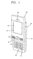
- Figure 1 is a perspective view illustrating a top sliding type mobile terminal.
- Figure 2 is an exploded view illustrating the top sliding type mobile terminal.
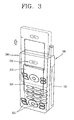
- Figure 3 is a perspective view illustrating operation of the top sliding type mobile terminal.
- the mobile terminal includes a body 100 having a lower portion that includes a keypad 110.
- the mobile terminal also includes a slider 200 configured to slidingly couple to the body 100.
- the mobile terminal also includes a longitudinal sliding unit coupled between the slider 200 and the body 100 such that the slider 200 may move longitudinally with respect to the body 100.
- the mobile terminal also includes a display unit 210 fixedly coupled to the slider 200.
- the body 100 may be constructed in a rectangle shape and have a certain thickness.
- a keypad 110 has a plurality of keys 111 and is placed in the body 100 such that the keys 111 may protrude outside of the body 100.
- the number of the keys 111 may be decreased because of limitations on the size of the area where the keys 111 are arranged. Therefore, each of the keys 111 may have both a function of entering numbers and a function of entering letters. That is, the primary function of the keys 111 is to enter numbers, but each of the keys 111 may also be used to enter a plurality of letters. Therefore, to input a message, the same key 111 may need to be pressed several times to input different letters.
- the slider 200 When in a first position, the slider 200 is placed on top of the body 100 such that the keys 111 are covered by the slider 200. When the slider 200 is moved in a longitudinal direction with respect to the body 100, the keys 111 are exposed to provide access to the keys 111 for a user. Furthermore, a battery 120 is detachably mounted on the lower surface of the body 100.
- a display unit 210 is provided on an outer surface of the slider 200.
- An operating keypad 220 is provided on the outer surface of the slider 200, below the display unit. Voice phone calls are made and terminated by pressing keys 221 on the operating keypad 220.
- a display window 211 of the display unit 210 is rectangular in shape and is oriented in the same longitudinal direction as the slider 200.
- the longitudinal sliding unit is provided on an inner surface of the body 100 and an inner surface of the slider 200.
- the longitudinal sliding unit includes a driving motor 310 provided in the body 100, a pinion 320 coupled to the driving motor 310, and a rack 330 mounted longitudinally on the inner surface of the slider 200 and having one side engaged with the pinion 320.
- Reference numerals 201, 101, 230 and 130 represent guide grooves, guide protrusions inserted into the guide grooves, a receiver and a microphone, respectively.
- a semi-automatic closing technique may be implemented in the mobile terminal using a wire spring.
- the amount of space required for the slider 200 to move is minimal, allowing for the mobile terminal to have increased structural strength.
- the amount of space required for the folder to move is increased because the folder needs to be opened and closed on an axis located at one end of the body. Furthermore, the structural strength of the folding mobile terminal is weakened when the folder is opened.
- the area on the body 100 that may be used for the keypad 110 is limited. Therefore, a small number of keys 111 are included in the keypad 110, necessitating that multiple functions must be assigned to each key 111. Furthermore, if letters are inputted using the keys 111, each key 111 must be pressed two or three times for each letter to be input. The above drawbacks may make the top sliding type mobile terminal inconvenient for sending and receiving text messages.
- the present invention is directed to a side sliding type mobile terminal that substantially obviates one or more problems due to limitations and disadvantages of the related art.
- An object of the present invention is to provide a side sliding type mobile terminal and a controlling method thereof capable of including an expanded keypad to simplify letter input by utilizing a wider area to increase the number of letter keys available to a user.
- a mobile terminal comprises a body comprising a keypad and a slider slidingly coupled to the body.
- the slider is configured to slide transversely with respect to the body and may comprise a display unit configured to display image information.
- the keypad may comprise keys arranged longitudinally with respect to the body.
- the slider may be configured to slide into a first position and a second position.
- the keypad may be covered by the slider when the slider is slid into the first position and the keypad may be exposed when the slider is slid into the second position.
- the slider may comprise a display unit configured to display image information.
- the mobile terminal may further comprise a processor coupled to the slider, configured to detect when the slider is slid from the first position to the second position and when the slider is slid from the second position to the first position.
- the image information may be rotated 90 degrees from a transverse orientation to a longitudinal orientation when the processor detects that the slider has been slid from the first position to the second position.
- the image information may be rotated 90 degrees from a longitudinal orientation to a transverse orientation when the processor detects that the slider has been slid from the second position to the first position.
- the slider may further comprise a number keypad for numerical input and an operational keypad for performance of call functions.
- the keypad may comprise letter keys and symbol keys, and may have a QWERTY key layout, for example.
- a mobile terminal in another embodiment, comprises a body having a length (longitudinal dimension) different from a width (transverse dimension), the body comprising a keypad having keys.
- the mobile terminal also comprises a transverse sliding unit coupled to the body and a slider, configured to enable the slider to slide transversely with respect to the body.
- the mobile terminal also comprises the slider coupled to the transverse sliding unit.
- a method of controlling a mobile terminal comprises transversely sliding a slider with respect to a body and detecting the sliding of the slider with respect to the body.
- the method also comprises rotating image information on a display unit of the slider to enable viewing of the image information by a user in response to the detecting of the sliding of the slider with respect to the body.
- the sliding of the slider may expose a keypad on the body to enable the user to perform text based communication. Conversely, the sliding of the slider may place the slider in a position on top of the body to enable the user to perform voice based communication.
- Figure 4 is a front view illustrating a side sliding type mobile terminal, according to one embodiment of the present invention.
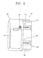
- Figures 5 and 6 are a front view and a rear view, respectively, illustrating a side sliding type mobile terminal in an opened configuration, according to one embodiment of the present invention.
- a side sliding type mobile terminal (mobile terminal) 505 includes a body 400.
- the mobile terminal 505 also includes a slider 500 configured to slidingly couple to the body 400.
- the length and the width of the body 400 may be different from each other.
- the length and the width of the slider 500 may be different from each other.
- the mobile terminal 505 also includes a transverse sliding unit 600 mounted between the body 400 and the slider 500 such that the slider 500 may move (e.g., slide) transversely with respect to the body 400.
- the body 400 may be constructed with a rectangular shape and may have a predetermined thickness, for example.
- the width of the body 400 may be smaller than the length of the body 400.
- Inner surfaces of the body 400 and the slider 500, respectively, are the surfaces that are mounted to the transverse sliding unit 600.
- Outer surfaces of the body 400 and the slider 500, respectively, are the surfaces opposite the inner surfaces of the body 400 and the slider 500.
- the inner surface of the body 400 may be divided into two sections, a first section being a key arrangement region, where a keypad 410 is located, and a second section being a mounting region for coupling with the transverse sliding unit 600.
- the keypad may preferably include a QWERTY keypad layout.
- the slider 500 may also be constructed with a rectangular shape and may have a predetermined thickness, for example.
- the inner surfaces of the body 400 and the slider 500 may have the same size and shape.
- a printed circuit board (PCB) or the like may be mounted within the slider 500.
- a number keypad 510 may be provided on the outer surface of the slider 500.
- Operating keys 520 may also be provided on the outer surface of the slider 500, such as for example, above the number keypad 510.
- a display unit 530 may be provided on the outer surface of the slider 500, such as for example, above the operating keys 520.
- a display window 531 may be formed in the display unit 530. The display window 531 may have a rectangular shape, with a width different from a length, for example.
- Figures 7 and 8 are an exploded perspective view and a cross-section view, respectively, illustrating a transverse sliding unit used in a side sliding type mobile terminal, according to one embodiment of the present invention.
- the transverse sliding unit 600 includes a rail body 610 coupled to the slider 500.
- the transverse sliding unit 600 also includes a rail guide 620 slidably coupled to the rail body 610 and fixedly coupled to the body 400.
- the transverse sliding unit 600 may also include a detachment unit such that the rail guide 620 may be detached from the rail body 610 at a set position of the rail body 610.
- the rail body 610 may include a base portion 611 coupled to the inside surface of the slider 500.
- the base portion 611 may be constructed with a rectangular shape and may have a predetermined thickness, for example.
- a rail groove 612 may be formed longitudinally in the base portion 611.
- the rail groove 612 may include a longitudinal groove portion 613 and transverse groove portions 614.
- the longitudinal groove portion 613 may have a specified width and depth and the transverse groove portions 614 may be constructed with a square shape at both sides of the surface of the longitudinal groove portion 613 closest to the slider.
- the rail body 610 may be fixedly coupled to the inner surface of the slider 500 such that the longitudinal dimension of the rail body 610 coincides with the transverse dimension of the slider 500.
- the rail body 610 may be coupled to the slider 500 by a fastener, such as for example, a screw.
- the rail guide 620 may include a rail portion 621 slidably coupled to the rail groove 612 and stopping portions 622 extending from both sides of the rail portion 621.
- the rail portion 621 may be constructed with a hexahedron shape and may have a width corresponding to the width of the rail groove 612, for example.
- a protrusion 623 may be formed at an upper surface of the hexahedron shaped rail portion 621.
- the stopping portions 622 may be constructed with a predetermined thickness and length at edges of the rail portion 621.
- the rail guide 620 may be coupled to the mounting region on the inner surface of the body 400 such that the longitudinal dimension of the rail guide 620 coincides with the transverse dimension of the body 400.
- the rail guide 620 may be coupled to the body 400 by a fastener, such as for example, a screw.
- the rail portion 621 and the stopping portions 622 may be inserted into the rail groove 612 to couple the rail guide 620 to the rail body 610.
- the detachment unit may include detachment grooves 615 formed in the rail groove 612.
- the detachment unit may also include an elastic detachment protrusion 624 formed on the rail portion 621 of the rail guide 620 and configured to be detached from the detachment grooves 615 by the elasticity of the elastic detachment protrusion 624.
- Two detachment grooves 615 may be formed at certain intervals of the rail groove 612.
- the elastic detachment groove 624 may preferably be protrudingly formed at or near the center of the surface of the rail portion 621 away from the body 400.
- a first detachment groove 615 may be located at half a length of the rail guide 620 from an end of the rail body 610, for example.
- a second detachment groove 615 may be located at half a length of the rail body 610 from an end of the rail guide 620, for example.
- two transverse sliding units 600 may be disposed at certain intervals of the slider 500.
- a buffering member 630 configured to smooth the sliding of the slider 500 with respect to the body 400 may be provided between the slider 500 and the body 400.
- the buffering member 630 may be constructed from lubrication-coated synthetic rubber wires, for example.
- Two buffering members 630 may be disposed at certain intervals of the slider 500, for example.
- a receiver 540 and a microphone 550 may be mounted on the outer surface of the slider 500.
- the receiver 540 may be mounted at an upper portion of the slider 500, for example, and the microphone 550 may be mounted on a lower portion of the slider 500, for example.
- a battery 420 and a speaker 430 may be detachably mounted to the outer surface of the body 400, for example.
- Figure 9 is a flow diagram illustrating a method for controlling a side sliding type mobile terminal, according to one embodiment of the present invention.
- the method of controlling the side sliding type mobile terminal comprises, at step 910, moving the slider 500, including the display unit 530, transversely with respect to the body 400.
- image information is displayed on the display unit 530, the display unit 530 turning 90 degrees upon detecting the movement of the slider 500.
- the body 400 and the slider 500 each have a length (longitudinal dimension) and a width (transverse dimension).
- the respective lengths of the body 400 and the slider 500 are longer than the respective widths of the body 400 and the slider 500. Longitudinal and transverse orientations are viewed with respect to lengths and widths of the body 400 and the slider 500.
- the slider 500 may preferably be slid transversely with respect to the body 400.
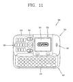
- Figures 10 and 11 are front views illustrating a side sliding type mobile terminal, according to one embodiment of the present invention.
- image information may be displayed transversely with respect to the body 400.
- the image information may be displayed longitudinally with respect to the body 400.
- the mobile terminal is used to make a voice call.
- the user inputs the telephone number of the receiving party by pressing the number keys 510 provided on the slider 500 and executes the call by pressing the operating keys 520.
- the user may end the call by pressing the operating keys 520.
- the user may answer an incoming call by pressing the operating keys 520.
- the user may end the call by pressing the operating keys 520.
- image information may be displayed transversely on the display unit 530 to enable convenient viewing by the user.
- the slider 500 may be positioned on top of the body 400.
- the mobile terminal is used for text based communication, such as for example, text messaging or Internet usage.
- the user may slide the slider 500 in a transverse direction with respect to the body 400, so that the letter keys 410 provided on the body 400 are exposed.
- the rail body 610 coupled to the slider 500 and the rail guide 620 coupled to the body 400 may slide with respect to each other. If the slider 500 is slid a certain distance with respect to the body 400, the elastic protrusion 624 of the rail guide 620 coupled to the slider 500 may insert into and fix the detachment groove 615 of the rail body 610, so that the slider 500 becomes fixed in place.
- the transverse movement of the slider 500 may be detected by a processor within the mobile terminal. When the transverse movement of the slider 500 is detected, the image information displayed on the display unit 530 may be rotated 90 degrees, for example.
- the user may rotate the mobile terminal 90 degrees such that the mobile terminal 'faces' the user for convenient text input. That is, the mobile terminal may be oriented such that the letter keys 410 are positioned to face the user, the display unit 530 is positioned above the letter keys 410, and the image information is displayed longitudinally on the display unit 530. The user may then input letters and/or symbols using the letter keys 410 provided on the body 400.
- the user may slide the slider 500 transversely with respect to the body 400 so that the slider 500 retracts and fits on top of the body 400.
- the elastic protrusion 624 may separate from the detachment groove 615 and be inserted into a different detachment groove 615 to fix the slider 500 in position on top of the body 400.
- the image information displayed on the display unit 530 may rotate 90 degrees so that the image information is displayed transversely.
- a mobile terminal comprises a body comprising a keypad and a slider slidingly coupled to the body.
- the slider is configured to slide transversely with respect to the body and may comprise a display unit configured to display image information.
- the keypad may comprise keys arranged longitudinally with respect to the body.
- the slider may be configured to slide into a first position and a second position.
- the keypad may be covered by the slider when the slider is slid into the first position and the keypad may be exposed when the slider is slid into the second position.
- the slider may comprise a display unit configured to display image information.
- the mobile terminal may further comprise a processor coupled to the slider, configured to detect when the slider is slid from the first position to the second position and when the slider is slid from the second position to the first position.
- the image information may be rotated 90 degrees from a transverse orientation to a longitudinal orientation when the processor detects that the slider has been slid from the first position to the second position.
- the image information may be rotated 90 degrees from a longitudinal orientation to a transverse orientation when the processor detects that the slider has been slid from the second position to the first position.
- the slider may further comprise a number keypad for numerical input and an operational keypad for performance of call functions.
- the keypad may comprise letter keys and symbol keys, and may have a QWERTY key layout, for example.
- a mobile terminal in another embodiment, comprises a body having a length (longitudinal dimension) different from a width (transverse dimension), the body comprising a keypad having keys.
- the mobile terminal also comprises a transverse sliding unit coupled to the body and a slider, configured to enable the slider to slide transversely with respect to the body.
- the mobile terminal also comprises the slider coupled to the transverse sliding unit.
- the keypad may be positioned on top of the body when the slider is in the first position.
- the slider may have the same width and length as the body on the surfaces of the slider and the body that couple to the transverse sliding unit, respectively.
- the transverse sliding unit may comprise a rail body coupled to the body or the slider, and a rail guide slidably coupled to the rail body and fixedly coupled to the body or the slider.
- the transverse sliding unit may further comprise a detachment unit configured to enable the rail guide to be detached from the rail body at a set position of the rail body.
- the detachment unit may comprise detachment grooves in the rail body, and an elastic detachment protrusion in the rail guide configured to couple with the detachment grooves.
- the rail body may comprise a base portion constructed with a rectangular shape and a predetermined thickness, and a rail groove formed longitudinally on a surface of the base portion.
- the rail guide may comprise a rail portion slidably coupled to the rail groove of the rail body, and stopping portions extending from both sides of the rail portion.
- the side sliding type mobile terminal may further comprise a buffering member coupled to the slider or the body, configured to buffer relative motion between the slider and the body.
- a method of controlling a mobile terminal comprises transversely sliding a slider with respect to a body and detecting the sliding of the slider with respect to the body.
- the method also comprises rotating image information on a display unit of the slider to enable viewing of the image information by a user in response to the detecting of the sliding of the slider with respect to the body.
- the sliding of the slider may expose a keypad on the body to enable the user to perform text based communication. Conversely, the sliding of the slider may place the slider in a position on top of the body to enable the user to perform voice based communication.
- the size of the mobile terminal may effectively decrease, allowing for greater portability. Furthermore, due to the side sliding type construction of the mobile terminal, the available area for arrangement of a letter keypad is increased. Additionally, since more area is available for a letter keypad, a key arrangement with a greater number of keys, such as for example, a QWERTY keypad may be included in the mobile terminal. Therefore, it may not be necessary to assign multiple functions to each key or to press a key several times to input a single letter.
- the image information display may be rotated 90 degrees in response to sliding of the slider, the image information may be conveniently viewed by the user, regardless of whether the mobile terminal is being used for a voice call or text based communication.
- the present invention may enable convenient text based communication while still providing a bar type mobile terminal for voice calls.
Abstract
Description
- The present invention relates generally to a mobile terminal, and more particularly to a sliding type mobile terminal.
- A mobile terminal is a communication device which permits mobile communication with another party. Mobile terminals are capable of voice communication, sending and receiving text messages, accessing the Internet, receiving television signals, and capturing still and video images and sending the captured images to the other party. Mobile terminals may have various types of construction, such as a top sliding type, a folder type, a flip type, and a bar type.
- Figure 1 is a perspective view illustrating a top sliding type mobile terminal. Figure 2 is an exploded view illustrating the top sliding type mobile terminal. Figure 3 is a perspective view illustrating operation of the top sliding type mobile terminal.
- Referring to Figure 1, the mobile terminal includes a
body 100 having a lower portion that includes akeypad 110. The mobile terminal also includes aslider 200 configured to slidingly couple to thebody 100. The mobile terminal also includes a longitudinal sliding unit coupled between theslider 200 and thebody 100 such that theslider 200 may move longitudinally with respect to thebody 100. The mobile terminal also includes adisplay unit 210 fixedly coupled to theslider 200. - The
body 100 may be constructed in a rectangle shape and have a certain thickness. Akeypad 110 has a plurality ofkeys 111 and is placed in thebody 100 such that thekeys 111 may protrude outside of thebody 100. However, the number of thekeys 111 may be decreased because of limitations on the size of the area where thekeys 111 are arranged. Therefore, each of thekeys 111 may have both a function of entering numbers and a function of entering letters. That is, the primary function of thekeys 111 is to enter numbers, but each of thekeys 111 may also be used to enter a plurality of letters. Therefore, to input a message, thesame key 111 may need to be pressed several times to input different letters. - When in a first position, the
slider 200 is placed on top of thebody 100 such that thekeys 111 are covered by theslider 200. When theslider 200 is moved in a longitudinal direction with respect to thebody 100, thekeys 111 are exposed to provide access to thekeys 111 for a user. Furthermore, abattery 120 is detachably mounted on the lower surface of thebody 100. - A
display unit 210 is provided on an outer surface of theslider 200. Anoperating keypad 220 is provided on the outer surface of theslider 200, below the display unit. Voice phone calls are made and terminated by pressingkeys 221 on theoperating keypad 220. Adisplay window 211 of thedisplay unit 210 is rectangular in shape and is oriented in the same longitudinal direction as theslider 200. - Referring to Figure 2, the longitudinal sliding unit is provided on an inner surface of the
body 100 and an inner surface of theslider 200. The longitudinal sliding unit includes adriving motor 310 provided in thebody 100, apinion 320 coupled to thedriving motor 310, and arack 330 mounted longitudinally on the inner surface of theslider 200 and having one side engaged with thepinion 320.Reference numerals - Referring to Figure 3, operation of the mobile terminal is described. When a user talks to another party using the mobile terminal, the user first moves the
slider 200 longitudinally to expose thekeypad 110. The user then inputs the other party's telephone number by pressing thekeys 111 and executes the call using thekeys 221 on theoperating keypad 220. After completing the call, the user moves theslider 200 longitudinally to cover thekeypad 110. Furthermore, to answer a call, the user moves theslider 200 longitudinally to expose thekeypad 110 and moves theslider 200 longitudinally to cover thekeypad 110 when the call is completed. Text messaging operates in a manner similar to voice calls. The user moves theslider 200 to expose thekeypad 110 and types letters, numbers and/or symbols by pressing thenumber keys 111. Since thekeys 111 on thenumber keypad 110 are primarily constructed for numerical input, each number may be entered with a single keystroke. However, to input letters or symbols requires the same key to be pressed two or three times. - Using the sliding type mobile terminal, the amount of space required for the
slider 200 to move is minimal, allowing for the mobile terminal to have increased structural strength. On the other hand, in a folder type mobile terminal, the amount of space required for the folder to move is increased because the folder needs to be opened and closed on an axis located at one end of the body. Furthermore, the structural strength of the folding mobile terminal is weakened when the folder is opened. - However, in the top sliding type mobile terminal, the area on the
body 100 that may be used for thekeypad 110 is limited. Therefore, a small number ofkeys 111 are included in thekeypad 110, necessitating that multiple functions must be assigned to eachkey 111. Furthermore, if letters are inputted using thekeys 111, eachkey 111 must be pressed two or three times for each letter to be input. The above drawbacks may make the top sliding type mobile terminal inconvenient for sending and receiving text messages. - Accordingly, the present invention is directed to a side sliding type mobile terminal that substantially obviates one or more problems due to limitations and disadvantages of the related art.
- An object of the present invention is to provide a side sliding type mobile terminal and a controlling method thereof capable of including an expanded keypad to simplify letter input by utilizing a wider area to increase the number of letter keys available to a user.
- Additional advantages, objects, and features of the invention will be set forth in part in the description which follows and in part will become apparent to those having ordinary skill in the art upon examination of the following or may be learned from practice of the invention. The objectives and other advantages of the invention may be realized and attained by the structure particularly pointed out in the written description and claims hereof as well as the appended drawings.
- To achieve these objects and other advantages and in accordance with the purpose of the invention, as embodied and broadly described herein, in one embodiment, a mobile terminal comprises a body comprising a keypad and a slider slidingly coupled to the body. The slider is configured to slide transversely with respect to the body and may comprise a display unit configured to display image information.
- The keypad may comprise keys arranged longitudinally with respect to the body. The slider may be configured to slide into a first position and a second position. The keypad may be covered by the slider when the slider is slid into the first position and the keypad may be exposed when the slider is slid into the second position.
- The slider may comprise a display unit configured to display image information. The mobile terminal may further comprise a processor coupled to the slider, configured to detect when the slider is slid from the first position to the second position and when the slider is slid from the second position to the first position. The image information may be rotated 90 degrees from a transverse orientation to a longitudinal orientation when the processor detects that the slider has been slid from the first position to the second position. Conversely, the image information may be rotated 90 degrees from a longitudinal orientation to a transverse orientation when the processor detects that the slider has been slid from the second position to the first position.
- The slider may further comprise a number keypad for numerical input and an operational keypad for performance of call functions. The keypad may comprise letter keys and symbol keys, and may have a QWERTY key layout, for example.
- In another embodiment, a mobile terminal comprises a body having a length (longitudinal dimension) different from a width (transverse dimension), the body comprising a keypad having keys. The mobile terminal also comprises a transverse sliding unit coupled to the body and a slider, configured to enable the slider to slide transversely with respect to the body. The mobile terminal also comprises the slider coupled to the transverse sliding unit.
- In yet another embodiment, a method of controlling a mobile terminal comprises transversely sliding a slider with respect to a body and detecting the sliding of the slider with respect to the body. The method also comprises rotating image information on a display unit of the slider to enable viewing of the image information by a user in response to the detecting of the sliding of the slider with respect to the body.
- The sliding of the slider may expose a keypad on the body to enable the user to perform text based communication. Conversely, the sliding of the slider may place the slider in a position on top of the body to enable the user to perform voice based communication.
- The foregoing and other objects, features, aspects and advantages of the present invention will become more apparent from the following detailed description of the present invention when taken in conjunction with the accompanying drawings. It is to be understood that both the foregoing general description and the following detailed description of the present invention are exemplary and explanatory and are intended to provide further explanation of the invention as claimed.
- The accompanying drawings, which are included to provide a further understanding of the invention and are incorporated in and constitute a part of this application, illustrate embodiments of the invention and together with the description serve to explain the principles of the invention.
- Figure 1 is a perspective view illustrating a top sliding type mobile terminal.
- Figure 2 is an exploded view illustrating the top sliding type mobile terminal.
- Figure 3 is a perspective view illustrating operation of the top sliding type mobile terminal.
- Figure 4 is a front view illustrating a side sliding type mobile terminal, according to one embodiment of the present invention.
- Figures 5 and 6 are a front view and a rear view, respectively, illustrating a side sliding type mobile terminal in an opened configuration, according to one embodiment of the present invention.
- Figures 7 and 8 are an exploded perspective view and a cross-section view, respectively, illustrating a transverse sliding unit used in a side sliding type mobile terminal, according to one embodiment of the present invention.
- Figure 9 is a flow diagram illustrating a method for controlling a side sliding type mobile terminal, according to one embodiment of the present invention.
- Figures 10 and 11 are front views illustrating a side sliding type mobile terminal, according to one embodiment of the present invention.
- Reference will now be made in detail to the preferred embodiments of the present invention, examples of which are illustrated in the accompanying drawings. Wherever possible, the same reference numbers will be used throughout the drawings to refer to the same or like parts.
- Figure 4 is a front view illustrating a side sliding type mobile terminal, according to one embodiment of the present invention. Figures 5 and 6 are a front view and a rear view, respectively, illustrating a side sliding type mobile terminal in an opened configuration, according to one embodiment of the present invention.
- Referring to Figures 4-6, a side sliding type mobile terminal (mobile terminal) 505 includes a
body 400. Themobile terminal 505 also includes aslider 500 configured to slidingly couple to thebody 400. The length and the width of thebody 400 may be different from each other. Similarly, the length and the width of theslider 500 may be different from each other. Themobile terminal 505 also includes a transverse slidingunit 600 mounted between thebody 400 and theslider 500 such that theslider 500 may move (e.g., slide) transversely with respect to thebody 400. - The
body 400 may be constructed with a rectangular shape and may have a predetermined thickness, for example. The width of thebody 400 may be smaller than the length of thebody 400. Inner surfaces of thebody 400 and theslider 500, respectively, are the surfaces that are mounted to the transverse slidingunit 600. Outer surfaces of thebody 400 and theslider 500, respectively, are the surfaces opposite the inner surfaces of thebody 400 and theslider 500. The inner surface of thebody 400 may be divided into two sections, a first section being a key arrangement region, where akeypad 410 is located, and a second section being a mounting region for coupling with the transverse slidingunit 600. The keypad may preferably include a QWERTY keypad layout. - The
slider 500 may also be constructed with a rectangular shape and may have a predetermined thickness, for example. The inner surfaces of thebody 400 and theslider 500 may have the same size and shape. A printed circuit board (PCB) or the like may be mounted within theslider 500. - A
number keypad 510 may be provided on the outer surface of theslider 500. Operatingkeys 520 may also be provided on the outer surface of theslider 500, such as for example, above thenumber keypad 510. Adisplay unit 530 may be provided on the outer surface of theslider 500, such as for example, above the operatingkeys 520. Adisplay window 531 may be formed in thedisplay unit 530. Thedisplay window 531 may have a rectangular shape, with a width different from a length, for example. - Figures 7 and 8 are an exploded perspective view and a cross-section view, respectively, illustrating a transverse sliding unit used in a side sliding type mobile terminal, according to one embodiment of the present invention.
- Referring to Figure 7, the transverse sliding
unit 600 includes arail body 610 coupled to theslider 500. The transverse slidingunit 600 also includes arail guide 620 slidably coupled to therail body 610 and fixedly coupled to thebody 400. The transverse slidingunit 600 may also include a detachment unit such that therail guide 620 may be detached from therail body 610 at a set position of therail body 610. - The
rail body 610 may include abase portion 611 coupled to the inside surface of theslider 500. Thebase portion 611 may be constructed with a rectangular shape and may have a predetermined thickness, for example. Arail groove 612 may be formed longitudinally in thebase portion 611. Therail groove 612 may include alongitudinal groove portion 613 andtransverse groove portions 614. Thelongitudinal groove portion 613 may have a specified width and depth and thetransverse groove portions 614 may be constructed with a square shape at both sides of the surface of thelongitudinal groove portion 613 closest to the slider. - The
rail body 610 may be fixedly coupled to the inner surface of theslider 500 such that the longitudinal dimension of therail body 610 coincides with the transverse dimension of theslider 500. Therail body 610 may be coupled to theslider 500 by a fastener, such as for example, a screw. - The
rail guide 620 may include arail portion 621 slidably coupled to therail groove 612 and stoppingportions 622 extending from both sides of therail portion 621. Therail portion 621 may be constructed with a hexahedron shape and may have a width corresponding to the width of therail groove 612, for example. Aprotrusion 623 may be formed at an upper surface of the hexahedron shapedrail portion 621. The stoppingportions 622 may be constructed with a predetermined thickness and length at edges of therail portion 621. - The
rail guide 620 may be coupled to the mounting region on the inner surface of thebody 400 such that the longitudinal dimension of therail guide 620 coincides with the transverse dimension of thebody 400. Therail guide 620 may be coupled to thebody 400 by a fastener, such as for example, a screw. Therail portion 621 and the stoppingportions 622 may be inserted into therail groove 612 to couple therail guide 620 to therail body 610. - Referring to Figure 8, the detachment unit may include
detachment grooves 615 formed in therail groove 612. The detachment unit may also include anelastic detachment protrusion 624 formed on therail portion 621 of therail guide 620 and configured to be detached from thedetachment grooves 615 by the elasticity of theelastic detachment protrusion 624. Twodetachment grooves 615 may be formed at certain intervals of therail groove 612. Theelastic detachment groove 624 may preferably be protrudingly formed at or near the center of the surface of therail portion 621 away from thebody 400. Afirst detachment groove 615 may be located at half a length of therail guide 620 from an end of therail body 610, for example. Asecond detachment groove 615 may be located at half a length of therail body 610 from an end of therail guide 620, for example. Furthermore, two transverse slidingunits 600 may be disposed at certain intervals of theslider 500. - A buffering
member 630 configured to smooth the sliding of theslider 500 with respect to thebody 400 may be provided between theslider 500 and thebody 400. The bufferingmember 630 may be constructed from lubrication-coated synthetic rubber wires, for example. Two bufferingmembers 630 may be disposed at certain intervals of theslider 500, for example. Areceiver 540 and amicrophone 550 may be mounted on the outer surface of theslider 500. Thereceiver 540 may be mounted at an upper portion of theslider 500, for example, and themicrophone 550 may be mounted on a lower portion of theslider 500, for example. Abattery 420 and aspeaker 430 may be detachably mounted to the outer surface of thebody 400, for example. - Figure 9 is a flow diagram illustrating a method for controlling a side sliding type mobile terminal, according to one embodiment of the present invention. Referring to Figure 9, the method of controlling the side sliding type mobile terminal comprises, at
step 910, moving theslider 500, including thedisplay unit 530, transversely with respect to thebody 400. Atstep 920, image information is displayed on thedisplay unit 530, thedisplay unit 530 turning 90 degrees upon detecting the movement of theslider 500. - The
body 400 and theslider 500 each have a length (longitudinal dimension) and a width (transverse dimension). The respective lengths of thebody 400 and theslider 500 are longer than the respective widths of thebody 400 and theslider 500. Longitudinal and transverse orientations are viewed with respect to lengths and widths of thebody 400 and theslider 500. Theslider 500 may preferably be slid transversely with respect to thebody 400. - Figures 10 and 11 are front views illustrating a side sliding type mobile terminal, according to one embodiment of the present invention.
- Referring to Figures 10 and 11, when the
slider 500 is positioned on top of thebody 400, image information may be displayed transversely with respect to thebody 400. However, when theslider 500 is slid transversely with respect to thebody 400 so that theslider 500 is no longer positioned on top thebody 400, i.e. theslider 500 is extended from thebody 400, the image information may be displayed longitudinally with respect to thebody 400. - Operation of the side sliding type mobile terminal is described below. In a first example, the mobile terminal is used to make a voice call. The user inputs the telephone number of the receiving party by pressing the
number keys 510 provided on theslider 500 and executes the call by pressing theoperating keys 520. When finished with the call, the user may end the call by pressing theoperating keys 520. Similarly, the user may answer an incoming call by pressing theoperating keys 520. When finished with the call, the user may end the call by pressing theoperating keys 520. In such voice call processes, image information may be displayed transversely on thedisplay unit 530 to enable convenient viewing by the user. Furthermore, during such voice call processes, theslider 500 may be positioned on top of thebody 400. - Referring again to Figure 10, in a second example, the mobile terminal is used for text based communication, such as for example, text messaging or Internet usage. The user may slide the
slider 500 in a transverse direction with respect to thebody 400, so that theletter keys 410 provided on thebody 400 are exposed. In the sliding of theslider 500 in the transverse direction, therail body 610 coupled to theslider 500 and therail guide 620 coupled to thebody 400 may slide with respect to each other. If theslider 500 is slid a certain distance with respect to thebody 400, theelastic protrusion 624 of therail guide 620 coupled to theslider 500 may insert into and fix thedetachment groove 615 of therail body 610, so that theslider 500 becomes fixed in place. The transverse movement of theslider 500 may be detected by a processor within the mobile terminal. When the transverse movement of theslider 500 is detected, the image information displayed on thedisplay unit 530 may be rotated 90 degrees, for example. - Referring to Figure 11, the user may rotate the mobile terminal 90 degrees such that the mobile terminal 'faces' the user for convenient text input. That is, the mobile terminal may be oriented such that the
letter keys 410 are positioned to face the user, thedisplay unit 530 is positioned above theletter keys 410, and the image information is displayed longitudinally on thedisplay unit 530. The user may then input letters and/or symbols using theletter keys 410 provided on thebody 400. - When the user has finished using the
letter keys 410, i.e. after sending a text messages or completing Internet usage, the user may slide theslider 500 transversely with respect to thebody 400 so that theslider 500 retracts and fits on top of thebody 400. As the user pushes theslider 500, theelastic protrusion 624 may separate from thedetachment groove 615 and be inserted into adifferent detachment groove 615 to fix theslider 500 in position on top of thebody 400. When theslider 500 is slid transversely to be positioned on top of thebody 400, the image information displayed on thedisplay unit 530 may rotate 90 degrees so that the image information is displayed transversely. - In one embodiment, a mobile terminal comprises a body comprising a keypad and a slider slidingly coupled to the body. The slider is configured to slide transversely with respect to the body and may comprise a display unit configured to display image information.
- The keypad may comprise keys arranged longitudinally with respect to the body. The slider may be configured to slide into a first position and a second position. The keypad may be covered by the slider when the slider is slid into the first position and the keypad may be exposed when the slider is slid into the second position.
- The slider may comprise a display unit configured to display image information. The mobile terminal may further comprise a processor coupled to the slider, configured to detect when the slider is slid from the first position to the second position and when the slider is slid from the second position to the first position. The image information may be rotated 90 degrees from a transverse orientation to a longitudinal orientation when the processor detects that the slider has been slid from the first position to the second position. Conversely, the image information may be rotated 90 degrees from a longitudinal orientation to a transverse orientation when the processor detects that the slider has been slid from the second position to the first position.
- The slider may further comprise a number keypad for numerical input and an operational keypad for performance of call functions. The keypad may comprise letter keys and symbol keys, and may have a QWERTY key layout, for example.
- In another embodiment, a mobile terminal comprises a body having a length (longitudinal dimension) different from a width (transverse dimension), the body comprising a keypad having keys. The mobile terminal also comprises a transverse sliding unit coupled to the body and a slider, configured to enable the slider to slide transversely with respect to the body. The mobile terminal also comprises the slider coupled to the transverse sliding unit.
- The keypad may be positioned on top of the body when the slider is in the first position. The slider may have the same width and length as the body on the surfaces of the slider and the body that couple to the transverse sliding unit, respectively.
- The transverse sliding unit may comprise a rail body coupled to the body or the slider, and a rail guide slidably coupled to the rail body and fixedly coupled to the body or the slider. The transverse sliding unit may further comprise a detachment unit configured to enable the rail guide to be detached from the rail body at a set position of the rail body. The detachment unit may comprise detachment grooves in the rail body, and an elastic detachment protrusion in the rail guide configured to couple with the detachment grooves. The rail body may comprise a base portion constructed with a rectangular shape and a predetermined thickness, and a rail groove formed longitudinally on a surface of the base portion. The rail guide may comprise a rail portion slidably coupled to the rail groove of the rail body, and stopping portions extending from both sides of the rail portion. The side sliding type mobile terminal may further comprise a buffering member coupled to the slider or the body, configured to buffer relative motion between the slider and the body.
- In yet another embodiment, a method of controlling a mobile terminal comprises transversely sliding a slider with respect to a body and detecting the sliding of the slider with respect to the body. The method also comprises rotating image information on a display unit of the slider to enable viewing of the image information by a user in response to the detecting of the sliding of the slider with respect to the body.
- The sliding of the slider may expose a keypad on the body to enable the user to perform text based communication. Conversely, the sliding of the slider may place the slider in a position on top of the body to enable the user to perform voice based communication.
- By transversely sliding the
slider 500 to be positioned on top of thebody 400, the size of the mobile terminal may effectively decrease, allowing for greater portability. Furthermore, due to the side sliding type construction of the mobile terminal, the available area for arrangement of a letter keypad is increased. Additionally, since more area is available for a letter keypad, a key arrangement with a greater number of keys, such as for example, a QWERTY keypad may be included in the mobile terminal. Therefore, it may not be necessary to assign multiple functions to each key or to press a key several times to input a single letter. Furthermore, since the image information display may be rotated 90 degrees in response to sliding of the slider, the image information may be conveniently viewed by the user, regardless of whether the mobile terminal is being used for a voice call or text based communication. Thus, the present invention may enable convenient text based communication while still providing a bar type mobile terminal for voice calls. - It will be apparent to those skilled in the art that various modifications and variations may be made in the present invention without departing from the spirit or scope of the inventions. For example, although the present invention applies to mobile terminals, it may also apply to other types of portable electronic devices. Thus, it is intended that the present invention covers the modifications and variations of this invention provided they come within the scope of the appended claims and their equivalents.
Claims (30)
- A mobile terminal, comprising:a body comprising a keypad; anda slider slidingly coupled to the body, configured to slide transversely with respect to the body, the slider comprising a display unit configured to display image information.
- The mobile terminal of claim 1, wherein the keypad comprises keys arranged longitudinally with respect to the body.
- The mobile terminal of claim 1, wherein the slider is configured to slide into a first position and a second position.
- The mobile terminal of claim 3, wherein the keypad is covered by the slider when the slider is slid into the first position and wherein the keypad is exposed when the slider is slid into the second position.
- The mobile terminal of claim 3, further comprising:a processor coupled to the slider, configured to detect when the slider is slid from the first position to the second position and when the slider is slid from the second position to the first position.
- The mobile terminal of claim 5, wherein the image information is rotated 90 degrees from a transverse orientation to a longitudinal orientation when the processor detects that the slider has been slid from the first position to the second position.
- The mobile terminal of claim 5, wherein the image information is rotated 90 degrees from a longitudinal orientation to a transverse orientation when the processor detects that the slider has been slid from the second position to the first position.
- The mobile terminal of claim 1, wherein the slider further comprises a number keypad for numerical input.
- The mobile terminal of claim 1, wherein the slider further comprises an operational keypad for performance of call functions.
- The mobile terminal of claim 1, wherein the keypad comprises letter keys and symbol keys.
- The mobile terminal of claim 10, wherein the keypad has a QWERTY key layout.
- A mobile terminal, comprising:a body having a length different from a width, the body comprising a keypad having keys;a transverse sliding unit coupled to the body and a slider, configured to enable the slider to slide transversely with respect to the body; andthe slider coupled to the transverse sliding unit.
- The mobile terminal of claim 12, wherein the keys of the keypad are arranged longitudinally with respect to the body.
- The mobile terminal of claim 12, wherein the keypad is covered by the slider when the slider is slid into a first position and wherein the keypad is exposed when the slider is slid into a second position.
- The mobile terminal of claim 14, wherein the slider comprises a display unit configured to display image information.
- The mobile terminal of claim 15, further comprising:a processor coupled to the slider, configured to detect when the slider is slid from the first position to the second position and when the slider is slid from the second position to the first position.
- The mobile terminal of claim 16, wherein the image information is rotated 90 degrees from a transverse orientation to a longitudinal orientation when the processor detects that the slider has been slid from the first position to the second position.
- The mobile terminal of claim 16, wherein the image information is rotated 90 degrees from a longitudinal orientation to a transverse orientation when the processor detects that the slider has been slid from the second position to the first position.
- The mobile terminal of claim 14, wherein the keypad is positioned on top of the body when the slider is in the first position.
- The mobile terminal of claim 19, wherein the slider has the same width and length as the body on the surfaces of the slider and the body that couple to the transverse sliding unit, respectively.
- The mobile terminal of claim 13, wherein the keypad has a QWERTY key layout.
- The mobile terminal of claim 12, wherein the transverse sliding unit comprises:a rail body coupled to the body or the slider; anda rail guide slidably coupled to the rail body and fixedly coupled to the body or the slider.
- The mobile terminal of claim 22, wherein the transverse sliding unit further comprises a detachment unit configured to enable the rail guide to be detached from the rail body at a set position of the rail body.
- The mobile terminal of claim 23, wherein the detachment unit comprises:detachment grooves in the rail body; andan elastic detachment protrusion in the rail guide configured to couple with the detachment grooves.
- The mobile terminal of claim 22, wherein the rail body comprises:a base portion constructed with a rectangular shape and a predetermined thickness; anda rail groove formed longitudinally on a surface of the base portion.
- The mobile terminal of claim 22, wherein the rail guide comprises:a rail portion slidably coupled to the rail groove of the rail body; andstopping portions extending from both sides of the rail portion.
- The mobile terminal of claim 12, further comprising:a buffering member coupled to the slider or the body, configured to buffer relative motion between the slider and the body.
- A method of controlling a mobile terminal, comprising:transversely sliding a slider with respect to a body;detecting the sliding of the slider with respect to the body; androtating image information on a display unit of the slider to enable viewing of the image information by a user in response to the detecting of the sliding of the slider with respect to the body.
- The method of claim 28, wherein the sliding of the slider exposes a keypad on the body to enable the user to perform text based communication.
- The method of claim 28, wherein the sliding of the slider places the slider in a position on top of the body to enable the user to perform voice based communication.
Applications Claiming Priority (1)
| Application Number | Priority Date | Filing Date | Title |
|---|---|---|---|
| KR1020040110676A KR100721337B1 (en) | 2004-12-22 | 2004-12-22 | Side sliding type electronic device and controlling methode thereof |
Publications (2)
| Publication Number | Publication Date |
|---|---|
| EP1675359A1 true EP1675359A1 (en) | 2006-06-28 |
| EP1675359B1 EP1675359B1 (en) | 2012-10-31 |
Family
ID=36061530
Family Applications (1)
| Application Number | Title | Priority Date | Filing Date |
|---|---|---|---|
| EP05019452A Not-in-force EP1675359B1 (en) | 2004-12-22 | 2005-09-07 | Mobile terminal comprising a transversely sliding housing carrying a display unit |
Country Status (6)
| Country | Link |
|---|---|
| US (2) | US7610069B2 (en) |
| EP (1) | EP1675359B1 (en) |
| JP (1) | JP2006178924A (en) |
| KR (1) | KR100721337B1 (en) |
| CN (2) | CN101540791B (en) |
| DE (1) | DE202005021699U1 (en) |
Cited By (8)
| Publication number | Priority date | Publication date | Assignee | Title |
|---|---|---|---|---|
| EP1895382A1 (en) | 2006-08-28 | 2008-03-05 | Research In Motion Limited | Three row qwerty keyboard layout for compact landscape portable handheld messaging devices |
| EP1895381A1 (en) * | 2006-08-28 | 2008-03-05 | Research In Motion Limited | Hybrid portrait-landscape handheld device with trackball navigation and qwerty hide-away keyboard |
| WO2009080869A1 (en) * | 2007-12-20 | 2009-07-02 | Nokia Corporation | Slide mechanism |
| WO2009101245A1 (en) * | 2008-02-14 | 2009-08-20 | Nokia Corporation | Information presentation based on display screen orientation |
| EP2151975A1 (en) | 2008-08-07 | 2010-02-10 | Hanbit Precision Co., Ltd. | Slide hinge module for mobile phone |
| WO2010030306A2 (en) * | 2008-09-12 | 2010-03-18 | Sony Ericsson Mobile Communications Ab | Electronic device with locking, movable displays |
| US11095761B1 (en) | 2020-07-24 | 2021-08-17 | Lg Electronics Inc. | Mobile terminal |
| EP3944597A1 (en) * | 2020-07-24 | 2022-01-26 | LG Electronics, Inc. | Slidable mobile terminal |
Families Citing this family (43)
| Publication number | Priority date | Publication date | Assignee | Title |
|---|---|---|---|---|
| KR100704031B1 (en) * | 2004-04-29 | 2007-04-04 | 삼성전자주식회사 | Double sliding-type portable communication device |
| KR100616197B1 (en) | 2004-08-24 | 2006-08-25 | 삼성전자주식회사 | Sliding apparatus for double sliding-type portable communication device |
| KR100721337B1 (en) * | 2004-12-22 | 2007-05-28 | 엘지전자 주식회사 | Side sliding type electronic device and controlling methode thereof |
| JP4568332B2 (en) * | 2005-09-20 | 2010-10-27 | スガツネ工業株式会社 | Portable device |
| WO2007060730A1 (en) * | 2005-11-25 | 2007-05-31 | Mitsubishi Denki Kabushiki Kaisha | Portable terminal |
| KR100845862B1 (en) * | 2006-04-25 | 2008-07-14 | 엘지전자 주식회사 | Mobile terminal |
| CN101102652A (en) * | 2006-07-07 | 2008-01-09 | 深圳富泰宏精密工业有限公司 | Sliding cover structure and portable electronic device using this cover |
| EP1887761A3 (en) * | 2006-08-08 | 2012-12-26 | Samsung Electronics Co., Ltd. | Mobile communications device with slidable and rotatable housing covering a qwerty keypad |
| JP2008076818A (en) * | 2006-09-22 | 2008-04-03 | Fujitsu Ltd | Mobile terminal device |
| TW200825869A (en) * | 2006-12-13 | 2008-06-16 | Kye Systems Corp | Computer input device |
| US8131902B2 (en) * | 2007-03-06 | 2012-03-06 | International Business Machines Corporation | Determining orientation of blade server inserted into a blade chassis |
| JP4450008B2 (en) | 2007-04-17 | 2010-04-14 | 株式会社カシオ日立モバイルコミュニケーションズ | Electronics |
| EP1988691B1 (en) * | 2007-05-02 | 2014-03-05 | Samsung Electronics Co., Ltd. | Sliding-type portable terminal |
| JP2009003614A (en) * | 2007-06-20 | 2009-01-08 | Sony Corp | Slide mechanism and electronic apparatus |
| TWI351209B (en) * | 2007-07-25 | 2011-10-21 | High Tech Comp Corp | Electronic apparatus and flexible printed circuit board thereof |
| US20090256861A1 (en) * | 2007-12-31 | 2009-10-15 | Motorola, Inc. | Device and Method for Managing the Orientation of Information Being Displayed on the Screen of a Device |
| JP2009278411A (en) * | 2008-05-15 | 2009-11-26 | Sony Ericsson Mobilecommunications Japan Inc | Portable device |
| JP2009284018A (en) | 2008-05-19 | 2009-12-03 | Fujitsu Ltd | Information terminal |
| ATE554410T1 (en) * | 2008-05-28 | 2012-05-15 | Lighting Science Group Corp | LAMP AND OPERATING PROCEDURES |
| US7953462B2 (en) | 2008-08-04 | 2011-05-31 | Vartanian Harry | Apparatus and method for providing an adaptively responsive flexible display device |
| KR101035126B1 (en) * | 2008-08-07 | 2011-05-19 | 주식회사 한빛티앤아이 | Slide hinge module for cellular phone with built-in key pad |
| JP2010093555A (en) * | 2008-10-08 | 2010-04-22 | Sharp Corp | Communication device, operation key display control method and operation key display control program |
| US20120106077A1 (en) * | 2008-10-31 | 2012-05-03 | Tracy Mark S | Extruding Material Through A Die To Produce A Computer Chassis |
| KR101019679B1 (en) * | 2008-11-17 | 2011-03-07 | 주식회사 한빛티앤아이 | Slide hinge module for mobile phone |
| CN101754621A (en) * | 2008-11-28 | 2010-06-23 | 深圳富泰宏精密工业有限公司 | Slide electronic device |
| US8463326B2 (en) * | 2009-02-23 | 2013-06-11 | Research In Motion Limited | Handheld electronic device transitionable between different configurations |
| US8103322B2 (en) * | 2009-02-27 | 2012-01-24 | Research In Motion Limited | Handheld electronic device having two device members slidable relative to a bridge |
| US8224407B2 (en) * | 2009-03-23 | 2012-07-17 | T-Mobile Usa, Inc. | Mobile device having a movable display and associated systems and methods |
| US8023975B2 (en) * | 2009-03-23 | 2011-09-20 | T-Mobile Usa, Inc. | Secondary status display for mobile device |
| US8391935B2 (en) * | 2009-03-23 | 2013-03-05 | T-Mobile Usa, Inc. | Multifunction mobile device having a movable element, such as a display, and associated functions |
| US20100299874A1 (en) * | 2009-05-27 | 2010-12-02 | Ming-Han Lin | Sliding Hinge |
| KR101578430B1 (en) * | 2009-07-13 | 2015-12-18 | 엘지전자 주식회사 | Portable terminal |
| CN101989170A (en) * | 2009-07-29 | 2011-03-23 | 深圳富泰宏精密工业有限公司 | Portable electronic device |
| JP5330934B2 (en) * | 2009-08-27 | 2013-10-30 | 京セラ株式会社 | Portable electronic device and display method of portable electronic device |
| KR101602229B1 (en) * | 2009-09-25 | 2016-03-10 | 엘지전자 주식회사 | Portable terminal |
| US9436219B2 (en) | 2010-05-12 | 2016-09-06 | Litl Llc | Remote control to operate computer system |
| US8938753B2 (en) | 2010-05-12 | 2015-01-20 | Litl Llc | Configurable computer system |
| JP5384430B2 (en) * | 2010-05-31 | 2014-01-08 | 株式会社Nttドコモ | Slide type moving mechanism and electronic equipment |
| GB2531970B (en) * | 2010-11-15 | 2016-08-17 | Edesix Ltd | Image recording apparatus |
| US10474409B2 (en) * | 2014-09-19 | 2019-11-12 | Lenovo (Beijing) Co., Ltd. | Response control method and electronic device |
| US11009907B2 (en) | 2019-01-18 | 2021-05-18 | Dell Products L.P. | Portable information handling system user interface selection based on keyboard configuration |
| US11347367B2 (en) | 2019-01-18 | 2022-05-31 | Dell Products L.P. | Information handling system see do user interface management |
| US11169653B2 (en) | 2019-01-18 | 2021-11-09 | Dell Products L.P. | Asymmetric information handling system user interface management |
Citations (5)
| Publication number | Priority date | Publication date | Assignee | Title |
|---|---|---|---|---|
| WO2000038332A1 (en) * | 1998-12-21 | 2000-06-29 | Intel Corporation | Electronic device with hidden keyboard |
| US6243595B1 (en) * | 1998-06-16 | 2001-06-05 | Nortel Networks Limited | Portable wireless communication device having an extendible section |
| EP1220517A1 (en) * | 2000-12-28 | 2002-07-03 | Koninklijke Philips Electronics N.V. | Electronic device comprising two movable parts in relation to each other |
| EP1312999A2 (en) | 2001-11-09 | 2003-05-21 | Nokia Corporation | Multifunction mobile communications device with slidable display screen |
| WO2004049150A2 (en) * | 2002-11-21 | 2004-06-10 | Danger, Inc. | Data processing device with adjuntable display and input devices with multiple orientations |
Family Cites Families (33)
| Publication number | Priority date | Publication date | Assignee | Title |
|---|---|---|---|---|
| US6665173B2 (en) * | 1999-12-20 | 2003-12-16 | Wireless Agents, Llc | Physical configuration of a hand-held electronic communication device |
| US6437973B1 (en) * | 2000-04-18 | 2002-08-20 | Hewlett-Packard Company | Modular mechanism for movable display |
| JP3964607B2 (en) | 2000-08-08 | 2007-08-22 | アルプス電気株式会社 | Portable information terminal |
| KR100470172B1 (en) | 2001-06-22 | 2005-02-04 | 주식회사 임팩트라 | Mobile Station having Display Part Convertible Vertical into Horizontal |
| US6636419B2 (en) * | 2001-08-09 | 2003-10-21 | Danger, Inc. | Handheld display and keyboard |
| JP2003125053A (en) * | 2001-10-18 | 2003-04-25 | Bosu & K Consulting Kk | Portable telephone |
| JP2003288154A (en) * | 2002-03-27 | 2003-10-10 | Casio Comput Co Ltd | Electronic apparatus |
| JP2003319042A (en) * | 2002-04-25 | 2003-11-07 | Matsushita Electric Ind Co Ltd | Portable terminal device |
| JP3910112B2 (en) * | 2002-06-21 | 2007-04-25 | シャープ株式会社 | Camera phone |
| US6847310B1 (en) * | 2002-06-21 | 2005-01-25 | Bsquare Corporation | Keyboard |
| US7305631B1 (en) * | 2002-09-30 | 2007-12-04 | Danger, Inc. | Integrated motion sensor for a data processing device |
| US6829139B1 (en) * | 2002-10-01 | 2004-12-07 | Danger, Inc. | Adjustable data processing display |
| US7277275B2 (en) * | 2003-04-09 | 2007-10-02 | Samsung Electronics Co., Ltd. | Portable computer having adjustable display |
| KR20040102680A (en) | 2003-05-29 | 2004-12-08 | 하경균 | Slide track of sliding type cellular phone |
| US7529571B2 (en) * | 2003-09-03 | 2009-05-05 | Samsung Electronics Co., Ltd. | Sliding/hinge apparatus for sliding/rotating type mobile terminals |
| KR100563696B1 (en) * | 2003-09-09 | 2006-03-28 | 엘지전자 주식회사 | Sliding structure of mobile phone of slide type |
| JP2005084955A (en) * | 2003-09-09 | 2005-03-31 | Hitachi Ltd | Personal digital assistant |
| US7107018B2 (en) * | 2003-09-12 | 2006-09-12 | Motorola, Inc. | Communication device having multiple keypads |
| KR100703339B1 (en) * | 2003-09-24 | 2007-04-03 | 삼성전자주식회사 | Sliding type portable wireless terminal and method for controlling sliding operation therein |
| US20050070348A1 (en) * | 2003-09-29 | 2005-03-31 | Inventec Appliances Corp. | Hand-held communication electronic apparatus having two slidable keypads |
| GB2407933B (en) * | 2003-11-06 | 2006-03-08 | Inventec Appliances Corp | Hand-held communication electronic apparatus having two slidable keypads |
| KR100617690B1 (en) * | 2003-11-10 | 2006-08-28 | 삼성전자주식회사 | Sliding type portable wireless terminal |
| US7092246B2 (en) * | 2003-11-18 | 2006-08-15 | Kabushiki Kaisha Toshiba | Apparatus for connecting a display to a body case of an electronic device |
| US7042711B2 (en) * | 2003-11-18 | 2006-05-09 | Kabushiki Kaisha Toshiba | Multi-functional electronic device with a continuously accessible pointing device |
| KR100532334B1 (en) * | 2003-11-26 | 2005-11-29 | 삼성전자주식회사 | Sliding/folding type portable digital communication device |
| KR100608726B1 (en) * | 2003-12-09 | 2006-08-04 | 엘지전자 주식회사 | Sliding type mobile phone both up and down direction |
| KR100655114B1 (en) * | 2004-03-26 | 2006-12-08 | 이근주 | module of slide type cellular phone |
| US7262761B1 (en) * | 2004-04-21 | 2007-08-28 | Danger, Inc. | User interface for detecting a data entry mode |
| WO2006030607A1 (en) * | 2004-09-14 | 2006-03-23 | Mitsubishi Denki Kabushiki Kaisha | Mobile device |
| US20060109980A1 (en) * | 2004-11-19 | 2006-05-25 | Yuichi Miyazaki | Portable wireless communication device |
| US7353053B2 (en) * | 2004-11-23 | 2008-04-01 | Oqo, Inc. | Non-binding sliding display for a handheld electronic device |
| EP1829338B1 (en) * | 2004-12-20 | 2008-12-03 | Nokia Corporation | Electronic device |
| KR100721337B1 (en) | 2004-12-22 | 2007-05-28 | 엘지전자 주식회사 | Side sliding type electronic device and controlling methode thereof |
-
2004
- 2004-12-22 KR KR1020040110676A patent/KR100721337B1/en not_active IP Right Cessation
-
2005
- 2005-09-07 EP EP05019452A patent/EP1675359B1/en not_active Not-in-force
- 2005-09-07 DE DE202005021699U patent/DE202005021699U1/en not_active Expired - Lifetime
- 2005-09-13 JP JP2005266120A patent/JP2006178924A/en active Pending
- 2005-09-15 US US11/228,740 patent/US7610069B2/en not_active Expired - Fee Related
- 2005-12-20 CN CN2009101335158A patent/CN101540791B/en not_active Expired - Fee Related
- 2005-12-20 CN CNB2005101339184A patent/CN100531236C/en not_active Expired - Fee Related
-
2009
- 2009-09-15 US US12/560,343 patent/US8938276B2/en not_active Expired - Fee Related
Patent Citations (5)
| Publication number | Priority date | Publication date | Assignee | Title |
|---|---|---|---|---|
| US6243595B1 (en) * | 1998-06-16 | 2001-06-05 | Nortel Networks Limited | Portable wireless communication device having an extendible section |
| WO2000038332A1 (en) * | 1998-12-21 | 2000-06-29 | Intel Corporation | Electronic device with hidden keyboard |
| EP1220517A1 (en) * | 2000-12-28 | 2002-07-03 | Koninklijke Philips Electronics N.V. | Electronic device comprising two movable parts in relation to each other |
| EP1312999A2 (en) | 2001-11-09 | 2003-05-21 | Nokia Corporation | Multifunction mobile communications device with slidable display screen |
| WO2004049150A2 (en) * | 2002-11-21 | 2004-06-10 | Danger, Inc. | Data processing device with adjuntable display and input devices with multiple orientations |
Cited By (16)
| Publication number | Priority date | Publication date | Assignee | Title |
|---|---|---|---|---|
| EP1895381A1 (en) * | 2006-08-28 | 2008-03-05 | Research In Motion Limited | Hybrid portrait-landscape handheld device with trackball navigation and qwerty hide-away keyboard |
| EP1895382A1 (en) | 2006-08-28 | 2008-03-05 | Research In Motion Limited | Three row qwerty keyboard layout for compact landscape portable handheld messaging devices |
| WO2009080869A1 (en) * | 2007-12-20 | 2009-07-02 | Nokia Corporation | Slide mechanism |
| US8121659B2 (en) | 2007-12-20 | 2012-02-21 | Nokia Corporation | Slide mechanism |
| US8217964B2 (en) | 2008-02-14 | 2012-07-10 | Nokia Corporation | Information presentation based on display screen orientation |
| WO2009101245A1 (en) * | 2008-02-14 | 2009-08-20 | Nokia Corporation | Information presentation based on display screen orientation |
| EP2243280A4 (en) * | 2008-02-14 | 2014-07-23 | Nokia Corp | Information presentation based on display screen orientation |
| EP2243280A1 (en) * | 2008-02-14 | 2010-10-27 | Nokia Corporation | Information presentation based on display screen orientation |
| US8531486B2 (en) | 2008-02-14 | 2013-09-10 | Nokia Corporation | Information presentation based on display screen orientation |
| EP2151975A1 (en) | 2008-08-07 | 2010-02-10 | Hanbit Precision Co., Ltd. | Slide hinge module for mobile phone |
| WO2010030306A3 (en) * | 2008-09-12 | 2010-11-25 | Sony Ericsson Mobile Communications Ab | Electronic device with locking, movable displays |
| WO2010030306A2 (en) * | 2008-09-12 | 2010-03-18 | Sony Ericsson Mobile Communications Ab | Electronic device with locking, movable displays |
| US11095761B1 (en) | 2020-07-24 | 2021-08-17 | Lg Electronics Inc. | Mobile terminal |
| EP3944598A1 (en) * | 2020-07-24 | 2022-01-26 | LG Electronics, Inc. | Slidable mobile terminal |
| EP3944597A1 (en) * | 2020-07-24 | 2022-01-26 | LG Electronics, Inc. | Slidable mobile terminal |
| US11474565B2 (en) | 2020-07-24 | 2022-10-18 | Lg Electronics Inc. | Mobile terminal |
Also Published As
| Publication number | Publication date |
|---|---|
| EP1675359B1 (en) | 2012-10-31 |
| JP2006178924A (en) | 2006-07-06 |
| CN1794752A (en) | 2006-06-28 |
| US7610069B2 (en) | 2009-10-27 |
| US20060135229A1 (en) | 2006-06-22 |
| CN100531236C (en) | 2009-08-19 |
| DE202005021699U1 (en) | 2009-06-04 |
| KR100721337B1 (en) | 2007-05-28 |
| KR20060071706A (en) | 2006-06-27 |
| US20100004038A1 (en) | 2010-01-07 |
| CN101540791B (en) | 2012-02-29 |
| US8938276B2 (en) | 2015-01-20 |
| CN101540791A (en) | 2009-09-23 |
Similar Documents
| Publication | Publication Date | Title |
|---|---|---|
| EP1675359B1 (en) | Mobile terminal comprising a transversely sliding housing carrying a display unit | |
| EP1804468B1 (en) | Mobile communication terminal having two keypads | |
| US6495784B2 (en) | Step keys, step key assembly, and terminal having the step key assembly | |
| US7620425B2 (en) | Mobile terminal having a plurality of displays | |
| US8155718B2 (en) | Sliding/hinge apparatus for sliding/rotating type mobile terminals | |
| KR100709808B1 (en) | Rotation slide type mobile communication terminal | |
| EP1720326B1 (en) | Portable terminal with two bodies being both foldable and slidable relative to each other | |
| US7697270B2 (en) | Portable electronic device | |
| EP1635541A2 (en) | Data input key for a portable apparatus and key array thereof | |
| US20060178176A1 (en) | Terminal | |
| JP2005086836A (en) | Slider assembly for mobile communication terminal device | |
| US7492892B2 (en) | Slide opening/closing type mobile device | |
| KR100663552B1 (en) | Portable terminal with movable keypad | |
| KR100721340B1 (en) | Side sliding type electronic device | |
| EP1783986A2 (en) | Sliding module of sliding-type portable terminal | |
| JP4340088B2 (en) | Mobile device | |
| EP1484921B1 (en) | Camera lens assembly for a portable terminal | |
| KR100631021B1 (en) | Slide type mobile communication terminal of multi direction sliding | |
| KR20050079361A (en) | Bilateral sliding type mobile communication terminal | |
| KR100652766B1 (en) | Data input apparatus for mobile communication terminal | |
| KR200388393Y1 (en) | Sliding assembly and portable phone having the same | |
| KR100727074B1 (en) | Slide type personal portable device | |
| KR20060020869A (en) | Sliding module for portable terminal | |
| KR20060001564A (en) | Display apparatus in mobile phone | |
| KR20060035030A (en) | A sliding mobile-phone |
Legal Events
| Date | Code | Title | Description |
|---|---|---|---|
| PUAI | Public reference made under article 153(3) epc to a published international application that has entered the european phase |
Free format text: ORIGINAL CODE: 0009012 |
|
| 17P | Request for examination filed |
Effective date: 20050907 |
|
| AK | Designated contracting states |
Kind code of ref document: A1 Designated state(s): AT BE BG CH CY CZ DE DK EE ES FI FR GB GR HU IE IS IT LI LT LU LV MC NL PL PT RO SE SI SK TR |
|
| AX | Request for extension of the european patent |
Extension state: AL BA HR MK YU |
|
| 17Q | First examination report despatched |
Effective date: 20061012 |
|
| AKX | Designation fees paid |
Designated state(s): AT BE BG CH CY CZ DE DK EE ES FI FR GB GR HU IE IS IT LI LT LU LV MC NL PL PT RO SE SI SK TR |
|
| APBK | Appeal reference recorded |
Free format text: ORIGINAL CODE: EPIDOSNREFNE |
|
| APBN | Date of receipt of notice of appeal recorded |
Free format text: ORIGINAL CODE: EPIDOSNNOA2E |
|
| APBR | Date of receipt of statement of grounds of appeal recorded |
Free format text: ORIGINAL CODE: EPIDOSNNOA3E |
|
| APAF | Appeal reference modified |
Free format text: ORIGINAL CODE: EPIDOSCREFNE |
|
| RAP1 | Party data changed (applicant data changed or rights of an application transferred) |
Owner name: LG ELECTRONICS INC. |
|
| APBT | Appeal procedure closed |
Free format text: ORIGINAL CODE: EPIDOSNNOA9E |
|
| GRAP | Despatch of communication of intention to grant a patent |
Free format text: ORIGINAL CODE: EPIDOSNIGR1 |
|
| RTI1 | Title (correction) |
Free format text: MOBILE TERMINAL COMPRISING A TRANSVERSELY SLIDING HOUSING CARRYING A DISPLAY UNIT |
|
| GRAS | Grant fee paid |
Free format text: ORIGINAL CODE: EPIDOSNIGR3 |
|
| GRAA | (expected) grant |
Free format text: ORIGINAL CODE: 0009210 |
|
| AK | Designated contracting states |
Kind code of ref document: B1 Designated state(s): AT BE BG CH CY CZ DE DK EE ES FI FR GB GR HU IE IS IT LI LT LU LV MC NL PL PT RO SE SI SK TR |
|
| REG | Reference to a national code |
Ref country code: GB Ref legal event code: FG4D Ref country code: CH Ref legal event code: EP |
|
| REG | Reference to a national code |
Ref country code: AT Ref legal event code: REF Ref document number: 582541 Country of ref document: AT Kind code of ref document: T Effective date: 20121115 |
|
| REG | Reference to a national code |
Ref country code: IE Ref legal event code: FG4D |
|
| REG | Reference to a national code |
Ref country code: DE Ref legal event code: R096 Ref document number: 602005036757 Country of ref document: DE Effective date: 20121227 |
|
| REG | Reference to a national code |
Ref country code: NL Ref legal event code: T3 |
|
| REG | Reference to a national code |
Ref country code: AT Ref legal event code: MK05 Ref document number: 582541 Country of ref document: AT Kind code of ref document: T Effective date: 20121031 |
|
| REG | Reference to a national code |
Ref country code: LT Ref legal event code: MG4D |
|
| PG25 | Lapsed in a contracting state [announced via postgrant information from national office to epo] |
Ref country code: SE Free format text: LAPSE BECAUSE OF FAILURE TO SUBMIT A TRANSLATION OF THE DESCRIPTION OR TO PAY THE FEE WITHIN THE PRESCRIBED TIME-LIMIT Effective date: 20121031 Ref country code: IS Free format text: LAPSE BECAUSE OF FAILURE TO SUBMIT A TRANSLATION OF THE DESCRIPTION OR TO PAY THE FEE WITHIN THE PRESCRIBED TIME-LIMIT Effective date: 20130228 Ref country code: LT Free format text: LAPSE BECAUSE OF FAILURE TO SUBMIT A TRANSLATION OF THE DESCRIPTION OR TO PAY THE FEE WITHIN THE PRESCRIBED TIME-LIMIT Effective date: 20121031 Ref country code: FI Free format text: LAPSE BECAUSE OF FAILURE TO SUBMIT A TRANSLATION OF THE DESCRIPTION OR TO PAY THE FEE WITHIN THE PRESCRIBED TIME-LIMIT Effective date: 20121031 Ref country code: ES Free format text: LAPSE BECAUSE OF FAILURE TO SUBMIT A TRANSLATION OF THE DESCRIPTION OR TO PAY THE FEE WITHIN THE PRESCRIBED TIME-LIMIT Effective date: 20130211 |
|
| PG25 | Lapsed in a contracting state [announced via postgrant information from national office to epo] |
Ref country code: BE Free format text: LAPSE BECAUSE OF FAILURE TO SUBMIT A TRANSLATION OF THE DESCRIPTION OR TO PAY THE FEE WITHIN THE PRESCRIBED TIME-LIMIT Effective date: 20121031 Ref country code: PL Free format text: LAPSE BECAUSE OF FAILURE TO SUBMIT A TRANSLATION OF THE DESCRIPTION OR TO PAY THE FEE WITHIN THE PRESCRIBED TIME-LIMIT Effective date: 20121031 Ref country code: PT Free format text: LAPSE BECAUSE OF FAILURE TO SUBMIT A TRANSLATION OF THE DESCRIPTION OR TO PAY THE FEE WITHIN THE PRESCRIBED TIME-LIMIT Effective date: 20130228 Ref country code: GR Free format text: LAPSE BECAUSE OF FAILURE TO SUBMIT A TRANSLATION OF THE DESCRIPTION OR TO PAY THE FEE WITHIN THE PRESCRIBED TIME-LIMIT Effective date: 20130201 Ref country code: CY Free format text: LAPSE BECAUSE OF FAILURE TO SUBMIT A TRANSLATION OF THE DESCRIPTION OR TO PAY THE FEE WITHIN THE PRESCRIBED TIME-LIMIT Effective date: 20121031 Ref country code: SI Free format text: LAPSE BECAUSE OF FAILURE TO SUBMIT A TRANSLATION OF THE DESCRIPTION OR TO PAY THE FEE WITHIN THE PRESCRIBED TIME-LIMIT Effective date: 20121031 Ref country code: LV Free format text: LAPSE BECAUSE OF FAILURE TO SUBMIT A TRANSLATION OF THE DESCRIPTION OR TO PAY THE FEE WITHIN THE PRESCRIBED TIME-LIMIT Effective date: 20121031 |
|
| PG25 | Lapsed in a contracting state [announced via postgrant information from national office to epo] |
Ref country code: AT Free format text: LAPSE BECAUSE OF FAILURE TO SUBMIT A TRANSLATION OF THE DESCRIPTION OR TO PAY THE FEE WITHIN THE PRESCRIBED TIME-LIMIT Effective date: 20121031 |
|
| PG25 | Lapsed in a contracting state [announced via postgrant information from national office to epo] |
Ref country code: EE Free format text: LAPSE BECAUSE OF FAILURE TO SUBMIT A TRANSLATION OF THE DESCRIPTION OR TO PAY THE FEE WITHIN THE PRESCRIBED TIME-LIMIT Effective date: 20121031 Ref country code: DK Free format text: LAPSE BECAUSE OF FAILURE TO SUBMIT A TRANSLATION OF THE DESCRIPTION OR TO PAY THE FEE WITHIN THE PRESCRIBED TIME-LIMIT Effective date: 20121031 Ref country code: SK Free format text: LAPSE BECAUSE OF FAILURE TO SUBMIT A TRANSLATION OF THE DESCRIPTION OR TO PAY THE FEE WITHIN THE PRESCRIBED TIME-LIMIT Effective date: 20121031 Ref country code: BG Free format text: LAPSE BECAUSE OF FAILURE TO SUBMIT A TRANSLATION OF THE DESCRIPTION OR TO PAY THE FEE WITHIN THE PRESCRIBED TIME-LIMIT Effective date: 20130131 Ref country code: CZ Free format text: LAPSE BECAUSE OF FAILURE TO SUBMIT A TRANSLATION OF THE DESCRIPTION OR TO PAY THE FEE WITHIN THE PRESCRIBED TIME-LIMIT Effective date: 20121031 |
|
| PG25 | Lapsed in a contracting state [announced via postgrant information from national office to epo] |
Ref country code: RO Free format text: LAPSE BECAUSE OF FAILURE TO SUBMIT A TRANSLATION OF THE DESCRIPTION OR TO PAY THE FEE WITHIN THE PRESCRIBED TIME-LIMIT Effective date: 20121031 |
|
| PLBE | No opposition filed within time limit |
Free format text: ORIGINAL CODE: 0009261 |
|
| STAA | Information on the status of an ep patent application or granted ep patent |
Free format text: STATUS: NO OPPOSITION FILED WITHIN TIME LIMIT |
|
| 26N | No opposition filed |
Effective date: 20130801 |
|
| REG | Reference to a national code |
Ref country code: DE Ref legal event code: R097 Ref document number: 602005036757 Country of ref document: DE Effective date: 20130801 |
|
| PG25 | Lapsed in a contracting state [announced via postgrant information from national office to epo] |
Ref country code: MC Free format text: LAPSE BECAUSE OF FAILURE TO SUBMIT A TRANSLATION OF THE DESCRIPTION OR TO PAY THE FEE WITHIN THE PRESCRIBED TIME-LIMIT Effective date: 20121031 |
|
| REG | Reference to a national code |
Ref country code: CH Ref legal event code: PL |
|
| REG | Reference to a national code |
Ref country code: IE Ref legal event code: MM4A |
|
| PG25 | Lapsed in a contracting state [announced via postgrant information from national office to epo] |
Ref country code: CH Free format text: LAPSE BECAUSE OF NON-PAYMENT OF DUE FEES Effective date: 20130930 Ref country code: LI Free format text: LAPSE BECAUSE OF NON-PAYMENT OF DUE FEES Effective date: 20130930 Ref country code: IE Free format text: LAPSE BECAUSE OF NON-PAYMENT OF DUE FEES Effective date: 20130907 |
|
| REG | Reference to a national code |
Ref country code: FR Ref legal event code: PLFP Year of fee payment: 11 |
|
| PG25 | Lapsed in a contracting state [announced via postgrant information from national office to epo] |
Ref country code: TR Free format text: LAPSE BECAUSE OF FAILURE TO SUBMIT A TRANSLATION OF THE DESCRIPTION OR TO PAY THE FEE WITHIN THE PRESCRIBED TIME-LIMIT Effective date: 20121031 |
|
| PG25 | Lapsed in a contracting state [announced via postgrant information from national office to epo] |
Ref country code: LU Free format text: LAPSE BECAUSE OF NON-PAYMENT OF DUE FEES Effective date: 20130907 Ref country code: HU Free format text: LAPSE BECAUSE OF FAILURE TO SUBMIT A TRANSLATION OF THE DESCRIPTION OR TO PAY THE FEE WITHIN THE PRESCRIBED TIME-LIMIT; INVALID AB INITIO Effective date: 20050907 |
|
| PGFP | Annual fee paid to national office [announced via postgrant information from national office to epo] |
Ref country code: NL Payment date: 20150811 Year of fee payment: 11 |
|
| PGFP | Annual fee paid to national office [announced via postgrant information from national office to epo] |
Ref country code: GB Payment date: 20150811 Year of fee payment: 11 Ref country code: DE Payment date: 20150811 Year of fee payment: 11 |
|
| PGFP | Annual fee paid to national office [announced via postgrant information from national office to epo] |
Ref country code: FR Payment date: 20150625 Year of fee payment: 11 |
|
| PGFP | Annual fee paid to national office [announced via postgrant information from national office to epo] |
Ref country code: IT Payment date: 20150915 Year of fee payment: 11 |
|
| REG | Reference to a national code |
Ref country code: DE Ref legal event code: R119 Ref document number: 602005036757 Country of ref document: DE |
|
| REG | Reference to a national code |
Ref country code: NL Ref legal event code: MM Effective date: 20161001 |
|
| GBPC | Gb: european patent ceased through non-payment of renewal fee |
Effective date: 20160907 |
|
| PG25 | Lapsed in a contracting state [announced via postgrant information from national office to epo] |
Ref country code: NL Free format text: LAPSE BECAUSE OF NON-PAYMENT OF DUE FEES Effective date: 20161001 |
|
| REG | Reference to a national code |
Ref country code: FR Ref legal event code: ST Effective date: 20170531 |
|
| PG25 | Lapsed in a contracting state [announced via postgrant information from national office to epo] |
Ref country code: DE Free format text: LAPSE BECAUSE OF NON-PAYMENT OF DUE FEES Effective date: 20170401 Ref country code: GB Free format text: LAPSE BECAUSE OF NON-PAYMENT OF DUE FEES Effective date: 20160907 Ref country code: FR Free format text: LAPSE BECAUSE OF NON-PAYMENT OF DUE FEES Effective date: 20160930 |
|
| PG25 | Lapsed in a contracting state [announced via postgrant information from national office to epo] |
Ref country code: IT Free format text: LAPSE BECAUSE OF NON-PAYMENT OF DUE FEES Effective date: 20160907 |