EP1683904A1 - Method for controlling the temperature of mixed water - Google Patents
Method for controlling the temperature of mixed water Download PDFInfo
- Publication number
- EP1683904A1 EP1683904A1 EP20050110806 EP05110806A EP1683904A1 EP 1683904 A1 EP1683904 A1 EP 1683904A1 EP 20050110806 EP20050110806 EP 20050110806 EP 05110806 A EP05110806 A EP 05110806A EP 1683904 A1 EP1683904 A1 EP 1683904A1
- Authority
- EP
- European Patent Office
- Prior art keywords
- temperature
- hot water
- water
- cold
- control
- Prior art date
- Legal status (The legal status is an assumption and is not a legal conclusion. Google has not performed a legal analysis and makes no representation as to the accuracy of the status listed.)
- Granted
Links
Images
Classifications
-
- G—PHYSICS
- G05—CONTROLLING; REGULATING
- G05D—SYSTEMS FOR CONTROLLING OR REGULATING NON-ELECTRIC VARIABLES
- G05D23/00—Control of temperature
- G05D23/01—Control of temperature without auxiliary power
- G05D23/13—Control of temperature without auxiliary power by varying the mixing ratio of two fluids having different temperatures
- G05D23/1393—Control of temperature without auxiliary power by varying the mixing ratio of two fluids having different temperatures characterised by the use of electric means
-
- A—HUMAN NECESSITIES
- A47—FURNITURE; DOMESTIC ARTICLES OR APPLIANCES; COFFEE MILLS; SPICE MILLS; SUCTION CLEANERS IN GENERAL
- A47L—DOMESTIC WASHING OR CLEANING; SUCTION CLEANERS IN GENERAL
- A47L15/00—Washing or rinsing machines for crockery or tableware
- A47L15/42—Details
- A47L15/4214—Water supply, recirculation or discharge arrangements; Devices therefor
- A47L15/4217—Fittings for water supply, e.g. valves or plumbing means to connect to cold or warm water lines, aquastops
-
- A—HUMAN NECESSITIES
- A47—FURNITURE; DOMESTIC ARTICLES OR APPLIANCES; COFFEE MILLS; SPICE MILLS; SUCTION CLEANERS IN GENERAL
- A47L—DOMESTIC WASHING OR CLEANING; SUCTION CLEANERS IN GENERAL
- A47L15/00—Washing or rinsing machines for crockery or tableware
- A47L15/42—Details
- A47L15/4287—Temperature measuring or regulating arrangements
-
- D—TEXTILES; PAPER
- D06—TREATMENT OF TEXTILES OR THE LIKE; LAUNDERING; FLEXIBLE MATERIALS NOT OTHERWISE PROVIDED FOR
- D06F—LAUNDERING, DRYING, IRONING, PRESSING OR FOLDING TEXTILE ARTICLES
- D06F33/00—Control of operations performed in washing machines or washer-dryers
- D06F33/30—Control of washing machines characterised by the purpose or target of the control
- D06F33/32—Control of operational steps, e.g. optimisation or improvement of operational steps depending on the condition of the laundry
- D06F33/34—Control of operational steps, e.g. optimisation or improvement of operational steps depending on the condition of the laundry of water filling
-
- D—TEXTILES; PAPER
- D06—TREATMENT OF TEXTILES OR THE LIKE; LAUNDERING; FLEXIBLE MATERIALS NOT OTHERWISE PROVIDED FOR
- D06F—LAUNDERING, DRYING, IRONING, PRESSING OR FOLDING TEXTILE ARTICLES
- D06F39/00—Details of washing machines not specific to a single type of machines covered by groups D06F9/00 - D06F27/00
- D06F39/08—Liquid supply or discharge arrangements
- D06F39/088—Liquid supply arrangements
-
- G—PHYSICS
- G05—CONTROLLING; REGULATING
- G05D—SYSTEMS FOR CONTROLLING OR REGULATING NON-ELECTRIC VARIABLES
- G05D23/00—Control of temperature
- G05D23/01—Control of temperature without auxiliary power
- G05D23/13—Control of temperature without auxiliary power by varying the mixing ratio of two fluids having different temperatures
- G05D23/1306—Control of temperature without auxiliary power by varying the mixing ratio of two fluids having different temperatures for liquids
- G05D23/132—Control of temperature without auxiliary power by varying the mixing ratio of two fluids having different temperatures for liquids with temperature sensing element
- G05D23/134—Control of temperature without auxiliary power by varying the mixing ratio of two fluids having different temperatures for liquids with temperature sensing element measuring the temperature of mixed fluid
- G05D23/1346—Control of temperature without auxiliary power by varying the mixing ratio of two fluids having different temperatures for liquids with temperature sensing element measuring the temperature of mixed fluid with manual temperature setting means
- G05D23/1353—Control of temperature without auxiliary power by varying the mixing ratio of two fluids having different temperatures for liquids with temperature sensing element measuring the temperature of mixed fluid with manual temperature setting means combined with flow controlling means
-
- A—HUMAN NECESSITIES
- A47—FURNITURE; DOMESTIC ARTICLES OR APPLIANCES; COFFEE MILLS; SPICE MILLS; SUCTION CLEANERS IN GENERAL
- A47L—DOMESTIC WASHING OR CLEANING; SUCTION CLEANERS IN GENERAL
- A47L2401/00—Automatic detection in controlling methods of washing or rinsing machines for crockery or tableware, e.g. information provided by sensors entered into controlling devices
- A47L2401/12—Water temperature
-
- A—HUMAN NECESSITIES
- A47—FURNITURE; DOMESTIC ARTICLES OR APPLIANCES; COFFEE MILLS; SPICE MILLS; SUCTION CLEANERS IN GENERAL
- A47L—DOMESTIC WASHING OR CLEANING; SUCTION CLEANERS IN GENERAL
- A47L2401/00—Automatic detection in controlling methods of washing or rinsing machines for crockery or tableware, e.g. information provided by sensors entered into controlling devices
- A47L2401/14—Water pressure or flow rate
-
- A—HUMAN NECESSITIES
- A47—FURNITURE; DOMESTIC ARTICLES OR APPLIANCES; COFFEE MILLS; SPICE MILLS; SUCTION CLEANERS IN GENERAL
- A47L—DOMESTIC WASHING OR CLEANING; SUCTION CLEANERS IN GENERAL
- A47L2401/00—Automatic detection in controlling methods of washing or rinsing machines for crockery or tableware, e.g. information provided by sensors entered into controlling devices
- A47L2401/20—Time, e.g. elapsed operating time
-
- A—HUMAN NECESSITIES
- A47—FURNITURE; DOMESTIC ARTICLES OR APPLIANCES; COFFEE MILLS; SPICE MILLS; SUCTION CLEANERS IN GENERAL
- A47L—DOMESTIC WASHING OR CLEANING; SUCTION CLEANERS IN GENERAL
- A47L2501/00—Output in controlling method of washing or rinsing machines for crockery or tableware, i.e. quantities or components controlled, or actions performed by the controlling device executing the controlling method
- A47L2501/01—Water supply, e.g. opening or closure of the water inlet valve
-
- A—HUMAN NECESSITIES
- A47—FURNITURE; DOMESTIC ARTICLES OR APPLIANCES; COFFEE MILLS; SPICE MILLS; SUCTION CLEANERS IN GENERAL
- A47L—DOMESTIC WASHING OR CLEANING; SUCTION CLEANERS IN GENERAL
- A47L2501/00—Output in controlling method of washing or rinsing machines for crockery or tableware, i.e. quantities or components controlled, or actions performed by the controlling device executing the controlling method
- A47L2501/28—Machine starting, e.g. normal start, restart after electricity cut-off or start scheduling
-
- A—HUMAN NECESSITIES
- A47—FURNITURE; DOMESTIC ARTICLES OR APPLIANCES; COFFEE MILLS; SPICE MILLS; SUCTION CLEANERS IN GENERAL
- A47L—DOMESTIC WASHING OR CLEANING; SUCTION CLEANERS IN GENERAL
- A47L2501/00—Output in controlling method of washing or rinsing machines for crockery or tableware, i.e. quantities or components controlled, or actions performed by the controlling device executing the controlling method
- A47L2501/32—Stopping or disabling machine operation, including disconnecting the machine from a network, e.g. from an electrical power supply
-
- D—TEXTILES; PAPER
- D06—TREATMENT OF TEXTILES OR THE LIKE; LAUNDERING; FLEXIBLE MATERIALS NOT OTHERWISE PROVIDED FOR
- D06F—LAUNDERING, DRYING, IRONING, PRESSING OR FOLDING TEXTILE ARTICLES
- D06F2105/00—Systems or parameters controlled or affected by the control systems of washing machines, washer-dryers or laundry dryers
- D06F2105/02—Water supply
- D06F2105/04—Water supply from separate hot and cold water inlets
-
- Y—GENERAL TAGGING OF NEW TECHNOLOGICAL DEVELOPMENTS; GENERAL TAGGING OF CROSS-SECTIONAL TECHNOLOGIES SPANNING OVER SEVERAL SECTIONS OF THE IPC; TECHNICAL SUBJECTS COVERED BY FORMER USPC CROSS-REFERENCE ART COLLECTIONS [XRACs] AND DIGESTS
- Y02—TECHNOLOGIES OR APPLICATIONS FOR MITIGATION OR ADAPTATION AGAINST CLIMATE CHANGE
- Y02B—CLIMATE CHANGE MITIGATION TECHNOLOGIES RELATED TO BUILDINGS, e.g. HOUSING, HOUSE APPLIANCES OR RELATED END-USER APPLICATIONS
- Y02B40/00—Technologies aiming at improving the efficiency of home appliances, e.g. induction cooking or efficient technologies for refrigerators, freezers or dish washers
-
- Y—GENERAL TAGGING OF NEW TECHNOLOGICAL DEVELOPMENTS; GENERAL TAGGING OF CROSS-SECTIONAL TECHNOLOGIES SPANNING OVER SEVERAL SECTIONS OF THE IPC; TECHNICAL SUBJECTS COVERED BY FORMER USPC CROSS-REFERENCE ART COLLECTIONS [XRACs] AND DIGESTS
- Y10—TECHNICAL SUBJECTS COVERED BY FORMER USPC
- Y10T—TECHNICAL SUBJECTS COVERED BY FORMER US CLASSIFICATION
- Y10T137/00—Fluid handling
- Y10T137/2496—Self-proportioning or correlating systems
- Y10T137/2499—Mixture condition maintaining or sensing
Definitions
- the invention relates to a method for controlling the temperature of mixed water, which is fed from separate cold and hot water feeds, and an apparatus for implementing the method.
- Method and apparatus are particularly applicable to program-controlled domestic appliances such as washing machines and dishwashers.
- a washing machine in which the switching valves are controlled by a thermostat adjustable to different temperatures.
- the thermostat switches off the hot water valve when the predetermined temperature is exceeded, the cold water valve can be brought into open position regardless of the switching state of the thermostat, or it can be controlled independently of the hot water supply.
- a disadvantage of this solution is that the water inlet takes place in several filling steps and usually a reheating after completion of the intake process is required.
- the solution described in DE 196 37 610 A1 provides, the valve-controlled cold and hot water inlets in the flow direction a mixing chamber nachzuordnen. This space acts as a buffer before the mixed water is forwarded into the tub.
- a thermal sensor is arranged, the measured data is transmitted to the control electronics. This solution ensures an inlet of mixed water with almost constant temperatures.
- the control takes place between two temperature levels.
- the accuracy with which the mixed water temperature can be adjusted depends on how close the switching levels are together. An increase in accuracy can be achieved with this type of control only with greater expenditure of time and a considerable overhead in the control and / or in the mechanical implementation.
- the invention has for its object to provide a method and apparatus for implementing this method, whereby a container is continuously filled with mixed water from separate cold and hot water supply within a short time and the temperature of the mixed water during the feeding process as constant as possible on a program or User predetermined value is kept.
- the process should be simple and insensitive to possible confounding factors.
- An essential aim of the invention is that the device for implementing the method can be produced in a simple and cost-effective manner.
- the control process always proceeds in one direction only: from higher to lower temperature values. If the hot water supply is initially only available, after the setpoint has been set, the Quantity of inflowing hot water throttled and the supply of cold water steadily increased. The temperature of the mixed water is adjusted downwards until the setpoint is reached. The control process is completed when the temperature of the incoming hot water is no longer rising, ie has reached the operating temperature of the hot water system and when the temperature of the mixed water is controlled down to its setpoint by the inflow of cold water.
- the process is implemented by a regulator with separate supply lines for cold and hot water and with a mechanical actuator, through which the supply lines are constantly opened or closed.
- An essential feature of the controller is that the mechanical actuator is only moved in one direction.
- the hot water pipe is fully open and the cold water pipe is blocked.
- the actuator is set in motion so that the opening of the hot water pipe is closed continuously and the cold water pipe is opened continuously.
- the actuator is stopped when the set temperature is reached.
- the actuator then assumes a position which, assuming stable conditions in the water supply, is maintained unchanged until the end of the intake process.
- FIG. 1 The process sequence according to the invention is described with reference to the diagram designated as FIG. 1.
- the diagram shows the temperature profile of the mixed water produced in accordance with the method according to the invention.
- T H is the operating temperature of the hot water system
- T K is the temperature of the cold water, which is assumed to be constant.
- T S denotes the desired temperature of the mixed water set by the program or user and to be set by means of the method according to the invention.
- the process When requesting hot water, for example for the main wash of a washing machine, the process begins at start time t A with the maximum possible hot water supply while blocking the cold water supply. As a rule, the water from the hot water connection will not immediately flow to the operating temperature T H of the hot water supply system. By discontinuous removal of water and thus caused prolonged standing in the domestic water network, the water cools down and initially enters a low, undefined temperature. According to the example shown in the diagram, the initial temperature of the hot water T A should be below the setpoint T s . Depending on the length of the supply lines, their isolation and the frequency of hot water withdrawals, the temperature of the incoming water will reach the operating temperature T H of the hot water supply system only after a certain period of time.
- t 2 denotes this time.
- the invention assumes that until then, the temperature of the incoming water rises steadily. The temperature rise is recorded by measurement and the measured data is fed to an intelligent evaluation system. The regulation begins when the temperature of the inflowing hot water has reached a value above the predetermined setpoint T S.
- this time delay is read as the time difference between t 0 and t 1 .
- An essential task in the technical implementation of the method is to keep this period of time between the theoretically earliest possible and the practically realizable time for the start of the scheme as small as possible.
- the system continuously throttles the hot water supply and continuously increases the cold water supply.
- the control process is completed when the inflowing hot water has reached the operating temperature T H and the flow rates of the cold water and the hot water are coordinated so that the temperature of the mixed water is set to its desired value T S. From this time t 3 to the inflowing amounts of cold and hot water are kept constant.
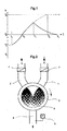
- Fig. 2 the controller for the production of mixed water at a predetermined temperature in accordance with the method of the invention is shown schematically.
- the cylindrical housing 3 of the regulator has two inlet channels 1 and 2, one each for the cold and hot water connection and a connection 4 for the mixed water to be discharged.
- the inlet openings are the same size. It may be advantageous to make the inlet for the hot water 2 larger in order to compensate for the lower water pressure in the hot water system.
- the water supply within the mechanical regulator is shown simplified in the drawing, on structural details, in particular those which serve a rapid mixing of the water streams was omitted.
- the outlet opening 4 is fully opened at each intermediate position of the rotary valve 6.
- the mixed water stream can be continuously supplied to its destination, for example to the tub of a washing machine.
- a thermal sensor 5 is integrated in the regulator housing near the outlet or in the outlet port 4.
- the arrangement of the thermal sensor 5 within the regulator housing allows the detection of the temperature directly at the point where the water flows from the cold and hot water pipe 1, 2 are mixed and discharged in a common drain line 4. This offers the advantage of detecting the temperature of the mixed water as a control variable at a very early point in time. The inertia of the mechanical control system and the resulting potential errors can thus be minimized.
- the mechanical actuator 6 is a rotary valve which is sealingly fitted into the housing 3 and is rotatably supported therein.
- a drive for the rotary valve 6 is a synchronous motor, not shown in the drawing.
- the actuator 6 acting as a rotary valve is moved in one direction only. This is shown in the drawing by the arrow.
- the initial state of the water discharge is determined by the fact that only hot water enters with the maximum possible amount.
- the rotary valve 6 assumes at the beginning of the process a position in which the hot water supply 2 is fully opened and the cold water supply 1 is locked.
- thermosensor 5 registers a temperature above the desired value T s
- the control process commences, control pulses being generated by an intelligent evaluation system which manipulate the actuator 6 in such a way that the cold water supply 1 is partially opened while at the same time reducing the supply of hot water.
- the rotary valve 6 is set in motion by the drive, not shown. The rotary movement of the actuator 6 in the direction of arrow causes a continuous closing of the hot water supply line 2 and at the same time a continuous opening of the cold water inlet 1. The rotary valve 6 is stopped when the temperature of the mixed water has reached the predetermined target value T S.
- the rotary valve 6 is set in motion again in the direction of the arrow via its drive. After reaching the operating temperature at time t 2 and the end of the control at time t 3 , the openings of the leads 1 and 2 are not changed. The rotary valve 6 adjusts to a position which, assuming stable conditions in the water supply, remains unchanged until the end of the mixed water supply.
- the control process always only takes place in one direction; when the setpoint is exceeded, the temperature of the mixed water is regulated downwards.
- the acting as an actuator rotary valve 6 must be moved only in one direction, a reversal of direction is not required, accordingly can be used as a drive for the rotary valve 6, a simple synchronous motor.
- the opposing opening or closing of the inlet openings 1 and 2 by only one rotational movement of the Actuator 6 causes the setpoint temperature for the mixed water can be set in a very short time for mechanical controller.
- a slower increase of the incoming hot water can lead to the fact that an excessive amount of underertemper vigilant water is introduced.
- it is provided to detect the increase in the temperature of the incoming hot water over time until reaching the setpoint temperature from t A to t 0 .
- the control of the mixing temperature after exceeding the setpoint temperature T H is delayed by an internally calculated period of time, ie the always present, inertia-related time difference t 1 - t 0 is extended computer-controlled for the purpose of compensation control.
- the heater can be turned on to nachzuarrin the lack of heat in the mixed water.
- the described measures for compensation of disturbances ensure that the process can always be controlled in one direction without readjustment and the actuator for the control process only has to be moved in one direction.
- This can be used as a drive for the actuator in a very simple manner, a synchronous motor without reversing the direction of rotation.
- a delay period is provided which must be exceeded before the shutdown occurs.
- This period of time can be permanently stored in the memory or calculated by the intelligent evaluation system, taking into account operational parameters such as the amount of temperature reduction, total intake volume or flow per unit time.
- the invention offers the further advantage that possible disturbances can be sufficiently absorbed by compensations that are easy to implement.
- the described rules for the compensation of possible disturbances ensure that the predetermined mixed water temperatures can be maintained with a tolerance sufficient for practical use.
Abstract
Description
Die Erfindung betrifft ein Verfahren zur Regelung der Temperatur von Mischwasser, das aus getrennten Kalt- und Warmwasserzuläufen gespeist wird, und eine Vorrichtung zur Realisierung des Verfahrens. Verfahren und Vorrichtung sind insbesondere anwendbar für programmgesteuerte Haushaltgeräte wie Wasch- und Geschirrspülmaschinen.The invention relates to a method for controlling the temperature of mixed water, which is fed from separate cold and hot water feeds, and an apparatus for implementing the method. Method and apparatus are particularly applicable to program-controlled domestic appliances such as washing machines and dishwashers.
Um die Vorteile einer zentralen Warmwasserbereitung in Bezug auf Heizkostensenkung sowie Verkürzung der Programmdauer effektiv auszunutzen, sind Geräte entwickelt worden, die je einen Anschluss für Kalt- und Warmwasser aufweisen und den Einlauf aus den beiden Wasseranschlüssen so steuern, dass das erzeugte Mischwasser im Reservoir genau die gewünschte Temperatur hat, beispielsweise die gewünschten 30°C Waschtemperatur in einem Laugenbehälter. Die Einstellung des Mischwassers auf eine vorbestimmte Temperatur kann in einfachster Weise über zwei in den beiden Zuleitungen angeordnete programmgesteuerte Sperrventile realisiert werden. Die Ventile werden zeitgetaktet geschaltet, so dass wechselseitig kaltes und warmes Wasser einfließt. Die Mischwassertemperatur wird über einen im Wasserreservoir angeordneten Thermosensor überwacht, dessen Messdaten zur Steuerung der Ventile dienen. Dieses einfache Verfahren ist sehr ungenau in Bezug auf die Temperaturregelung und führt in der Regel zu einem erhöhten Wasser- oder Energieverbrauch. Der wesentliche Nachteil besteht jedoch darin, dass zeitweilig Wasser mit hoher Temperatur einläuft. Dies kann dazu führen, dass im Falle einer Waschmaschine empfindliche Textilien Schaden nehmen.In order to effectively exploit the benefits of centralized water heating in terms of reducing heating costs and shortening the duration of the program, units have been developed, each with a connection for hot and cold water and control the inlet from the two water connections so that the mixing water produced in the reservoir exactly desired temperature, for example, the desired 30 ° C washing temperature in a tub. The setting of the mixed water to a predetermined temperature can be realized in the simplest way via two arranged in the two supply lines programmable shut-off valves. The valves are switched over in time so that cold and warm water flows in alternately. The mixed water temperature is monitored by means of a thermosensor arranged in the water reservoir, the measured data of which serve to control the valves. This simple process is very inaccurate in terms of temperature control and usually results in increased water or energy consumption. The main disadvantage, however, is that temporarily enters high temperature water. This can cause sensitive textiles to be damaged in the case of a washing machine.
Aus DE 197 17 449 A1 ist ein Waschautomat bekannt, bei dem die Schaltventile über einen auf unterschiedliche Temperaturen einstellbaren Thermostaten gesteuert werden. Der Thermostat schaltet das Warmwasserventil beim Überschreiten der vorgegebenen Temperatur ab, das Kaltwasserventil kann unabhängig vom Schaltzustand des Thermostaten in Öffnungsstellung gebracht werden, oder es kann unabhängig vom Warmwasserzulauf ansteuerbar sein. Nachteilig ist bei dieser Lösung, dass der Wassereinlauf in mehreren Füllschritten erfolgt und in der Regel ein Nachheizen nach Abschluss des Einlassvorganges erforderlich ist. Die in der DE 196 37 610 A1 beschriebene Lösung sieht vor, den ventilgesteuerten Kalt- und Warmwassereinläufen in Fließrichtung einen Mischraum nachzuordnen. Dieser Raum fungiert als Zwischenspeicher, bevor das Mischwasser in den Laugenbehälter weitergeleitet wird. Im Mischbehälter ist ein Thermosensor angeordnet, dessen Messdaten an die Steuerelektronik übertragen werden. Diese Lösungsvariante sichert einen Zulauf von Mischwasser mit nahezu konstanten Temperaturen.From DE 197 17 449 A1, a washing machine is known in which the switching valves are controlled by a thermostat adjustable to different temperatures. The thermostat switches off the hot water valve when the predetermined temperature is exceeded, the cold water valve can be brought into open position regardless of the switching state of the thermostat, or it can be controlled independently of the hot water supply. A disadvantage of this solution is that the water inlet takes place in several filling steps and usually a reheating after completion of the intake process is required. The solution described in DE 196 37 610 A1 provides, the valve-controlled cold and hot water inlets in the flow direction a mixing chamber nachzuordnen. This space acts as a buffer before the mixed water is forwarded into the tub. In the mixing container, a thermal sensor is arranged, the measured data is transmitted to the control electronics. This solution ensures an inlet of mixed water with almost constant temperatures.
Bei den beschriebenen Verfahren erfolgt die Regelung zwischen zwei Temperaturniveaus. Die Genauigkeit, mit der die Mischwassertemperatur eingestellt werden kann, hängt davon ab, wie dicht die Schaltniveaus zusammenliegen. Eine Steigerung der Genauigkeit ist bei dieser Art der Regelung nur mit höherem Zeitaufwand und einem erheblichen Mehraufwand bei der Steuerung und/oder bei der mechanischen Umsetzung erzielbar.In the described method, the control takes place between two temperature levels. The accuracy with which the mixed water temperature can be adjusted depends on how close the switching levels are together. An increase in accuracy can be achieved with this type of control only with greater expenditure of time and a considerable overhead in the control and / or in the mechanical implementation.
Der Nachteil der bekannten Lösungen mit im Wechsel getakteten Wassereinläufen kann vermieden werden durch die Verwendung eines mechanischen Stellglieds, das die Durchflussmengen von Kalt- und Warmwasser durch kontinuierliches Vergrößern bzw. Verkleinern der beiden Einlassöffnungen regelt. Mit dieser mechanisch geregelten Mischwasserzufuhr ist ein kontinuierlicher und damit schneller Wassereinlauf möglich. Der Aufwand für diese Art der Regelung ist aber sehr hoch, insbesondere für den Antrieb des Stellgliedes.The disadvantage of the known solutions with alternately clocked water inlets can be avoided by the use of a mechanical actuator, which regulates the flow rates of cold and hot water by continuously increasing or decreasing the two inlet openings. With this mechanically controlled mixed water supply a continuous and thus fast water intake is possible. The cost of this type of control is very high, especially for the drive of the actuator.
Der Erfindung liegt die Aufgabe zugrunde, ein Verfahren und eine Vorrichtung zur Realisierung dieses Verfahrens anzugeben, womit ein Behälter kontinuierlich mit Mischwasser aus getrennten Kalt- und Warmwasserzuleitungen binnen kurzer Zeit befüllt wird und die Temperatur des Mischwassers während des Einspeisungsvorganges möglichst konstant auf einem vom Programm oder Nutzer vorbestimmten Wert gehalten wird. Der Ablauf des Verfahrens soll einfach und gegenüber möglichen Störfaktoren unempfindlich sein. Ein wesentliches Ziel der Erfindung besteht darin, dass die Vorrichtung zur Umsetzung des Verfahrens unkompliziert und kostengünstig produziert werden kann.The invention has for its object to provide a method and apparatus for implementing this method, whereby a container is continuously filled with mixed water from separate cold and hot water supply within a short time and the temperature of the mixed water during the feeding process as constant as possible on a program or User predetermined value is kept. The process should be simple and insensitive to possible confounding factors. An essential aim of the invention is that the device for implementing the method can be produced in a simple and cost-effective manner.
Die Aufgabe der Erfindung wird durch die in den Ansprüchen 1 und 7 genannten Merkmale gelöst. Vorteilhafte Ausgestaltungen der Erfindung sind in den jeweiligen Unteransprüchen enthalten.The object of the invention is achieved by the features mentioned in
Gemäß dem erfindungsgemäßen Verfahren läuft der Regelvorgang immer nur in einer Richtung ab: von höheren zu niedrigeren Temperaturwerten. Bei zunächst ausschließlicher Warmwasserzufuhr wird nach Überschreiten des eingestellten Sollwertes die Menge des einfließenden Warmwassers gedrosselt und die Zufuhr von Kaltwasser stetig erhöht. Die Temperatur des Mischwassers wird nach unten geregelt, bis der Sollwert erreicht ist. Der Regelprozess ist abgeschlossen, wenn die Temperatur des einlaufenden Warmwassers nicht mehr steigt, also die Betriebstemperatur des Warmwassersystems erreicht hat und wenn durch den Zulauf von Kaltwasser die Temperatur des Mischwassers auf ihren Sollwert herunter geregelt ist.According to the method according to the invention, the control process always proceeds in one direction only: from higher to lower temperature values. If the hot water supply is initially only available, after the setpoint has been set, the Quantity of inflowing hot water throttled and the supply of cold water steadily increased. The temperature of the mixed water is adjusted downwards until the setpoint is reached. The control process is completed when the temperature of the incoming hot water is no longer rising, ie has reached the operating temperature of the hot water system and when the temperature of the mixed water is controlled down to its setpoint by the inflow of cold water.
Realisiert wird das Verfahren durch einen Regler mit getrennten Zulaufleitungen für Kalt- und Warmwasser und mit einem mechanischen Stellglied, durch welches die Zulaufleitungen stetig geöffnet bzw. verschlossen werden. Wesentliches Merkmal des Reglers besteht darin, dass das mechanische Stellglied nur in einer Richtung bewegt wird.The process is implemented by a regulator with separate supply lines for cold and hot water and with a mechanical actuator, through which the supply lines are constantly opened or closed. An essential feature of the controller is that the mechanical actuator is only moved in one direction.
Zu Beginn des Wassereinlaufs ist die Warmwasserleitung voll geöffnet und die Kaltwasserleitung gesperrt. Zur Regelung der Mischwassertemperatur wird das Stellglied so in Bewegung gesetzt, dass die Öffnung der Warmwasserleitung stetig geschlossen und die der Kaltwasserleitung stetig geöffnet wird. Das Stellglied wird angehalten, wenn die Solltemperatur erreicht ist. Nach Abschluss der Regelung werden die Öffnungen der Zuleitungen nicht mehr verändert, das Stellglied nimmt dann eine Position ein, die, stabile Bedingungen bei der Wasserzufuhr vorausgesetzt, bis zum Ende des Einlassvorgangs unverändert beibehalten wird.At the beginning of the water inlet, the hot water pipe is fully open and the cold water pipe is blocked. To control the mixed water temperature, the actuator is set in motion so that the opening of the hot water pipe is closed continuously and the cold water pipe is opened continuously. The actuator is stopped when the set temperature is reached. After completion of the regulation, the openings of the supply lines are no longer changed, the actuator then assumes a position which, assuming stable conditions in the water supply, is maintained unchanged until the end of the intake process.
Damit entfällt die Notwendigkeit, eine Nachregelung vornehmen zu müssen oder eine Regelung in Intervallen zwischen einem oberen und einem unteren Grenzwert. Der einfache, nur in eine Richtung wirkende Regelmechanismus des erfindungsgemäßen Verfahrens ist mit geringem regelungstechnischen Aufwand zu realisieren. Für den praktischen Betrieb, beispielsweise für den einer Waschmaschine, sind die mit dem Verfahren erzielbaren Parameter völlig ausreichend, die Wassertemperatur im Laugenbehälter ist in engen Toleranzen einstellbar und auch ausreichend genau reproduzierbar. Das Befüllen des Laugenbehälters mit Mischwasser ist in kurzer Zeit möglich, da der Vorgang gemäß der Erfindung ohne Unterbrechung abläuft. Vorteilhaft ist auch, dass das Mischwasser, abgesehen von einer kurzen Startphase, mit nahezu konstanter Temperatur einfließt. Beschädigungen von temperaturempfindlichen Textilien durch Kontakt mit zu warmem Wasser sind ausgeschlossen. Ein wesentlicher Vorteil des erfindungsgemäßen Verfahrens besteht darin, dass es sehr kostengünstig umsetzbar ist. Es kann insbesondere auf ein einfaches mechanisches Regelsystem zurückgegriffen werden, das mit einem Antrieb ohne Richtungsumkehr ausgestattet ist.This eliminates the need to re-adjust or regulate at intervals between upper and lower limits. The simple, only acting in one direction control mechanism of the method according to the invention can be realized with little control effort. For practical operation, for example, for a washing machine, the achievable with the method parameters are completely sufficient, the water temperature in the tub is adjustable in tight tolerances and also sufficiently accurate reproducible. The filling of the tub with mixed water is possible in a short time, since the process proceeds according to the invention without interruption. It is also advantageous that, apart from a short start-up phase, the mixed water flows in at a virtually constant temperature. Damage to temperature-sensitive textiles through contact with warm water is excluded. A significant advantage of the method according to the invention is that it can be implemented very inexpensively. It can be specific to one simple mechanical control system is used, which is equipped with a drive without reversal.
Die Erfindung soll nachstehend anhand eines in der Zeichnung dargestellten Ausführungsbeispiels erläutert werden. Es zeigen
- Fig. 1
- ein Temperatur/Zeit-Diagramm beim Befüllen einer Waschmaschine gemäß dem Verfahren nach der Erfindung und
- Fig. 2
- eine Regler, durch den das erfindungsgemäße Verfahren realisiert werden kann.
- Fig. 1
- a temperature / time diagram when filling a washing machine according to the method of the invention and
- Fig. 2
- a controller by which the inventive method can be realized.
Der erfindungsgemäße Verfahrensablauf ist anhand des als Fig. 1 bezeichneten Diagramms beschrieben. Dabei wird beispielsweise Bezug genommen auf den Betrieb einer Waschmaschine. Im Diagramm ist der Temperaturverlauf des nach Maßgabe des erfindungsgemäßen Verfahrens erzeugten Mischwassers dargestellt. Dabei bedeuten TH die Betriebstemperatur des Warmwassersystems und TK die Temperatur des Kaltwassers, die als konstant angenommen wird. Zwischen diesen Niveaus liegend bezeichnet TS die vom Programm oder Nutzer vorgegebene und mittels des erfindungsgemäßen Verfahrens einzustellende Solltemperatur des Mischwassers.The process sequence according to the invention is described with reference to the diagram designated as FIG. 1. For example, reference is made to the operation of a washing machine. The diagram shows the temperature profile of the mixed water produced in accordance with the method according to the invention. In this case, T H is the operating temperature of the hot water system and T K is the temperature of the cold water, which is assumed to be constant. Between these levels, T S denotes the desired temperature of the mixed water set by the program or user and to be set by means of the method according to the invention.
Bei Anforderung von Warmwasser, beispielsweise für den Hauptwaschgang einer Waschmaschine, beginnt der Prozess zum Startzeitpunkt tA mit der maximal möglichen Warmwasserzufuhr bei gleichzeitiger Sperrung der Kaltwasserzufuhr. In der Regel wird das Wasser aus dem Warmwasseranschluss nicht sofort mit der Betriebstemperatur TH des Warmwasserversorgungssystem einströmen. Durch diskontinuierliche Wasserentnahme und dadurch verursachtes längeres Stehen im Hauswassernetz kühlt sich das Wasser ab und läuft zunächst mit einer niedrigen, undefinierten Temperatur ein. Gemäß dem im Diagramm dargestellten Beispiel soll die Anfangstemperatur des Warmwassers TA unterhalb des Sollwertes Ts liegen. In Abhängigkeit von der Länge der Zuführungsleitungen, ihrer Isolierung und der Häufigkeit von Warmwasserentnahmen wird die Temperatur des einlaufenden Wassers erst nach einer gewissen Zeitspanne die Betriebstemperatur TH des Warmwasserversorgungssystems erreichen. Auf der Zeitachse des Diagramms bezeichnet t2 diesen Zeitpunkt. Die Erfindung geht davon aus, dass bis dahin die Temperatur des einströmenden Wassers stetig steigt. Der Temperaturanstieg wird messtechnisch erfasst und die Messdaten einem intelligenten Auswertesystem zugeführt. Die Regelung setzt ein, wenn die Temperatur des einfließenden Warmwassers einen Wert oberhalb des vorgegebenen Sollwertes TS erreicht hat.When requesting hot water, for example for the main wash of a washing machine, the process begins at start time t A with the maximum possible hot water supply while blocking the cold water supply. As a rule, the water from the hot water connection will not immediately flow to the operating temperature T H of the hot water supply system. By discontinuous removal of water and thus caused prolonged standing in the domestic water network, the water cools down and initially enters a low, undefined temperature. According to the example shown in the diagram, the initial temperature of the hot water T A should be below the setpoint T s . Depending on the length of the supply lines, their isolation and the frequency of hot water withdrawals, the temperature of the incoming water will reach the operating temperature T H of the hot water supply system only after a certain period of time. On the time axis of the diagram, t 2 denotes this time. The invention assumes that until then, the temperature of the incoming water rises steadily. The temperature rise is recorded by measurement and the measured data is fed to an intelligent evaluation system. The regulation begins when the temperature of the inflowing hot water has reached a value above the predetermined setpoint T S.
Wegen der Trägheit des Systems wird der Beginn der Regelung etwas verzögert. Im Diagramm ist diese Zeitverzögerung ablesbar als die Zeitdifferenz zwischen t0 und t1. Eine wesentliche Aufgabe bei der technischen Umsetzung des Verfahrens ist es, diese Zeitspanne zwischen dem theoretisch frühest möglichen und dem praktisch realisierbaren Zeitpunkt für den Beginn der Regelung möglichst klein zu halten.Because of the inertia of the system, the start of the scheme is delayed somewhat. In the diagram, this time delay is read as the time difference between t 0 and t 1 . An essential task in the technical implementation of the method is to keep this period of time between the theoretically earliest possible and the practically realizable time for the start of the scheme as small as possible.
Ab dem Zeitpunkt t1 wird vom System die Warmwasserzufuhr stetig gedrosselt und die Kaltwasserzufuhr kontinuierlich erhöht. Der Regelvorgang ist abgeschlossen, wenn das einfließende Warmwasser die Betriebstemperatur TH erreicht hat und die Mengenströme des Kaltwassers und des Warmwassers so aufeinander abgestimmt sind, dass die Temperatur des Mischwassers auf seinen Sollwert TS eingestellt ist. Von diesem Zeitpunkt t3 an werden die einfließenden Kalt- und Warmwassermengen konstant gehalten.From time t 1 , the system continuously throttles the hot water supply and continuously increases the cold water supply. The control process is completed when the inflowing hot water has reached the operating temperature T H and the flow rates of the cold water and the hot water are coordinated so that the temperature of the mixed water is set to its desired value T S. From this time t 3 to the inflowing amounts of cold and hot water are kept constant.
In Fig. 2 ist der Regler für die Erzeugung von Mischwasser mit einer vorbestimmten Temperatur nach Maßgabe des erfindungsgemäßen Verfahrens schematisch dargestellt. Das zylindrische Gehäuse 3 des Reglers weist zwei Einlasskanäle 1 und 2 auf, je einen für den Kalt- und den Warmwasseranschluss sowie einen Anschluss 4 für das abzuführende Mischwasser. In der Darstellung der Fig. 2 sind die Einlassöffnungen gleich groß. Es kann vorteilhaft sein, den Einlass für das Warmwasser 2 größer auszulegen, um einen gewissen Ausgleich für den geringeren Wasserdruck im Warmwassersystem zu schaffen.In Fig. 2, the controller for the production of mixed water at a predetermined temperature in accordance with the method of the invention is shown schematically. The cylindrical housing 3 of the regulator has two inlet channels 1 and 2, one each for the cold and hot water connection and a
Die Wasserführung innerhalb des mechanischen Reglers ist in der Zeichnung vereinfacht dargestellt, auf konstruktive Einzelheiten, insbesondere auf solche die einer schnellen Durchmischung der Wasserströme dienen, wurde verzichtet. Die Auslassöffnung 4 ist bei jeder Zwischenstellung des Drehschiebers 6 vollständig geöffnet. Dadurch kann der Mischwasserstrom seinem Bestimmungsort, beispielsweise dem Laugenbehälter einer Waschmaschine, kontinuierlich zugeführt werden. In das Reglergehäuse nahe der Auslassöffnung oder im Auslaufanschluss 4 ist ein Thermosensor 5 integriert. Die Anordnung des Thermosensors 5 innerhalb des Reglergehäuses gestattet die Erfassung der Temperatur unmittelbar an der Stelle, wo die Wasserströme aus der Kalt- und der Warmwasserleitung 1, 2 vermischt und in einer gemeinsamen Abflussleitung 4 abgeleitet werden. Dies bietet den Vorteil, die Temperatur des Mischwassers als Steuergröße zu einem sehr frühen Zeitpunkt zu erfassen. Die Trägheit des mechanischen Regelsystems und die sich daraus ergebenden möglichen Fehler können somit minimiert werden.The water supply within the mechanical regulator is shown simplified in the drawing, on structural details, in particular those which serve a rapid mixing of the water streams was omitted. The
Das mechanische Stellglied 6 ist ein Drehschieber, der in das Gehäuse 3 dichtend eingepasst ist und in diesem drehbar gelagert ist. Als Antrieb für den Drehschieber 6 dient ein in der Zeichnung nicht dargestellter Synchronmotor. Nach Maßgabe der Erfindung wird der als Stellglied 6 wirkende Drehschieber nur in eine Richtung bewegt. Dies wird in der Zeichnung durch den Pfeil dargestellt. Der Anfangszustand der Wassereinleitung ist dadurch bestimmt, dass nur Warmwasser mit der maximal möglichen Menge einläuft. Der Drehschieber 6 nimmt zu Beginn des Vorganges eine Position ein, bei der der Warmwasserzulauf 2 vollständig geöffnet und der Kaltwasseranschluss 1 gesperrt ist. Wird vom Thermosensor 5 eine Temperatur über den Sollwert Ts registriert, setzt der Regelprozess ein, wobei über ein intelligentes Auswertesystem Steuerimpulse erzeugt werden, die das Stellglied 6 in der Weise manipulieren, dass die Kaltwasserzuführung 1 partiell geöffnet wird bei gleichzeitig verringerter Zuführung von Warmwasser. Dazu wird der Drehschieber 6 durch den nicht dargestellten Antrieb in Bewegung versetzt. Die Drehbewegung des Stellgliedes 6 in Pfeilrichtung bewirkt ein kontinuierliches Verschließen der Warmwasserzuleitung 2 und zugleich ein stetiges Öffnen des Kaltwasserzulaufs 1. Der Drehschieber 6 wird angehalten, wenn die Temperatur des Mischwassers den vorgegebenen Sollwert TS erreicht hat. Steigt die Temperatur weiterhin an, weil am Warmwassereinlauf 2 die Betriebstemperatur TH noch nicht erreicht ist, wird über seinen Antrieb der Drehschieber 6 in Pfeilrichtung erneut in Bewegung gesetzt. Nach dem Erreichen der Betriebstemperatur zum Zeitpunkt t2 und dem Ende der Regelung zum Zeitpunkt t3 werden die Öffnungen der Zuleitungen 1 und 2 nicht mehr verändert. Der Drehschieber 6 stellt sich auf eine Position ein, die, stabile Bedingungen bei der Wasserzufuhr vorausgesetzt, bis zum Ende der Mischwasserzufuhr unverändert bleibt.The mechanical actuator 6 is a rotary valve which is sealingly fitted into the housing 3 and is rotatably supported therein. As a drive for the rotary valve 6 is a synchronous motor, not shown in the drawing. According to the invention, the actuator 6 acting as a rotary valve is moved in one direction only. This is shown in the drawing by the arrow. The initial state of the water discharge is determined by the fact that only hot water enters with the maximum possible amount. The rotary valve 6 assumes at the beginning of the process a position in which the hot water supply 2 is fully opened and the cold water supply 1 is locked. If the
Der Regelvorgang läuft immer nur in einer Richtung ab, bei Überschreiten des eingestellten Sollwertes wird die Temperatur des Mischwassers nach unten geregelt. Dazu muss der als Stellglied wirkende Drehschieber 6 nur in eine Richtung bewegt werden, eine Drehrichtungsumkehr ist nicht erforderlich, entsprechend kann als Antrieb für den Drehschieber 6 ein einfacher Synchronmotor eingesetzt werden. Das gegensinnige Öffnen bzw. Verschließen der Einlassöffnungen 1 und 2 durch nur eine Drehbewegung des Stellgliedes 6 bewirkt, dass die Solltemperatur für das Mischwasser in einer für mechanische Regler sehr kurzen Zeit eingestellt werden kann.The control process always only takes place in one direction; when the setpoint is exceeded, the temperature of the mixed water is regulated downwards. For this purpose, the acting as an actuator rotary valve 6 must be moved only in one direction, a reversal of direction is not required, accordingly can be used as a drive for the rotary valve 6, a simple synchronous motor. The opposing opening or closing of the inlet openings 1 and 2 by only one rotational movement of the Actuator 6 causes the setpoint temperature for the mixed water can be set in a very short time for mechanical controller.
Um die Betriebssicherheit des Verfahrens und des dieses Verfahren realisierenden Reglers zu verbessern, sind in Ausgestaltung der Erfindung Regeln vorgesehen, die mögliche Störfaktoren kompensieren. Als Störfaktoren sollen in diesem Zusammenhang solche Ereignisse und Zustände verstanden werden, die dazu führen können, dass das Mischwasser nach dem Beenden des erfindungsgemäß geregelten Zulaufs an seinem Bestimmungsort nicht die vorbestimmte Temperatur hat bzw. diese außerhalb zulässiger Toleranzen liegt.In order to improve the operational safety of the method and the controller implementing this method, rules are provided in an embodiment of the invention which compensate possible interference factors. In this context, disturbing factors are understood as meaning those events and states which can lead to the mixing water not having the predetermined temperature after termination of the feed regulated according to the invention at its destination or being outside the permissible tolerances.
In der Praxis sind zwei mögliche Störungen besonders wichtig. Das betrifft zum einen den sehr langsamen Anstieg der Warmwassertemperatur zu Beginn des Einlasses, und zum anderen das Absinken der Mischwassertemperatur, nachdem die Regelung abgeschlossen ist (nach t3).In practice, two possible disorders are particularly important. This concerns, on the one hand, the very slow rise of the hot water temperature at the beginning of the inlet and, on the other hand, the drop in the mixed water temperature after the control is completed (after t 3 ).
Ein verlangsamtes Ansteigen des einlaufenden Warmwassers kann dazu führen, dass eine zu große Menge untertemperierten Wassers eingeleitet wird. Um dafür einen Ausgleich zu schaffen, ist vorgesehen, den Anstieg der Temperatur des einlaufenden Warmwassers über die Zeit bis zum Erreichen der Solltemperatur von tA bis t0 zu erfassen. In Abhängigkeit von den gewonnenen Messdaten wird die Regelung der Mischtemperatur nach Überschreiten der Solltemperatur TH um eine intern berechnete Zeitspanne verzögert, d.h. die immer vorhandene, trägheitsbedingte Zeitdifferenz t1 - t0 wird rechnergesteuert zwecks Ausgleichsregelung verlängert. In der Praxis ist es zumeist ausreichend, lediglich die Zeit bis zum Erreichen der Solltemperatur (t0 - tA) des einlaufenden Warmwassers zu erfassen, um daraus den Korrekturwert für die verzögerte Regelung zu bestimmen.A slower increase of the incoming hot water can lead to the fact that an excessive amount of unterertemperierten water is introduced. To compensate for this, it is provided to detect the increase in the temperature of the incoming hot water over time until reaching the setpoint temperature from t A to t 0 . Depending on the measured data obtained, the control of the mixing temperature after exceeding the setpoint temperature T H is delayed by an internally calculated period of time, ie the always present, inertia-related time difference t 1 - t 0 is extended computer-controlled for the purpose of compensation control. In practice, it is usually sufficient to record only the time until the setpoint temperature (t 0 -t A ) of the incoming hot water is reached in order to determine the correction value for the delayed control.
Als Störfall gilt auch, wenn entgegen der eingangs gemachten Annahme die Temperatur des Warmwassers während des Zulaufs absinkt. Störungen dieser Art können durch Ausfälle im externen Heizsystem oder durch Defekte in den Leitungen hervorgerufen werden. Häufiger wird der Fall eintreten, dass der Druck in der Warmwasserleitung durch vorübergehend sehr starke Wasserentnahme an verschiedenen Zapfstellen absinkt. Aus einem solchen Druckabfall ergibt sich dann bei weiterhin konstantem Druck in der Kaltwasserleitung ein Absinken der Mischwassertemperatur. Da gemäß der Erfindung die Mischwassertemperatur nur zu niedrigen Werten geregelt werden kann, ist in Ausgestaltung der Erfindung vorgesehen, den Vorgang abzubrechen und unter Ausgangsbedingungen neu zu starten.An accident also applies if, contrary to the assumption made at the beginning, the temperature of the hot water drops during the inflow. Faults of this kind can be caused by failures in the external heating system or by defects in the lines. More often it will be the case that the pressure in the hot water pipe drops due to temporarily very strong water extraction at different tapping points. From such a pressure drop then results in a constant pressure in the cold water line, a drop in the mixed water temperature. Since according to the invention the Mixed water temperature can be controlled only to low values, is provided in an embodiment of the invention, cancel the process and restart under starting conditions.
Dazu werden zunächst die Einlasskanäle 1, 2 über die beiden Sperrventile 7 verschlossen, das Stellglied 6 in Pfeilrichtung bis in die Ausgangsposition gedreht und anschließend die Einlasskanäle 1, 2 erneut geöffnet. Der Wasserzulauf wird fortgesetzt bei geschlossenem Kaltwasseranschluss 1 und maximal geöffnetem Warmwasserzulauf 2. Danach läuft der Prozess so ab wie oben beschrieben.For this purpose, first the inlet channels 1, 2 are closed via the two shut-off
Hat der Auffangbehälter für das Mischwasser eine eigene Heizung, dann kann natürlich alternativ auch die Heizung eingeschaltet werden, um die fehlende Wärme im Mischwasser nachzuliefern.If the collecting container for the mixed water has its own heating, then of course, alternatively, the heater can be turned on to nachzuliefern the lack of heat in the mixed water.
Die beschriebenen Maßnahmen zur Kompensation von Störungen sichert ab, dass der Prozess ohne Nachregelung immer in einer Richtung gesteuert werden kann und das Stellglied für den Regelvorgang nur in eine Richtung bewegt werden muss. Damit kann als Antrieb für das Stellglied in sehr einfacher Weise ein Synchronmotor ohne Drehrichtungsumkehr eingesetzt werden.The described measures for compensation of disturbances ensure that the process can always be controlled in one direction without readjustment and the actuator for the control process only has to be moved in one direction. This can be used as a drive for the actuator in a very simple manner, a synchronous motor without reversing the direction of rotation.
Um nicht Gefahr zu laufen, dass jedes kurzzeitige Absinken der Temperatur zu einer Unterbrechung des Einlasses mit nachfolgendem Neustart des Vorganges führt, ist eine Verzögerungszeitspanne vorgesehen, die überschritten werden muss, bevor die Abschaltung erfolgt. Diese Zeitspanne kann fest vorgegeben im Speicher hinterlegt sein oder durch das intelligente Auswertesystem berechnet werden, unter Berücksichtigung betriebsbedingter Parameter wie Höhe der Temperaturabsenkung, Gesamteinlassmenge oder Durchfluss pro Zeiteinheit.To avoid the risk of any short-term drop in temperature leading to an interruption of the inlet with a subsequent restart of the process, a delay period is provided which must be exceeded before the shutdown occurs. This period of time can be permanently stored in the memory or calculated by the intelligent evaluation system, taking into account operational parameters such as the amount of temperature reduction, total intake volume or flow per unit time.
Die andere Möglichkeit, dass die Temperatur oder der Druck des zulaufenden Warmwassers nach der Einstellung der Mischwassertemperatur auf ihren Sollwert noch einmal ansteigt, wird vom System nicht als Störung interpretiert, sondern als Regelfall, der in der beschriebenen Weise abläuft, also als Korrektur der Mischwassertemperatur nach unten realisiert durch eine entsprechende Korrekturbewegung des Drehschiebers 6.The other possibility that the temperature or the pressure of the incoming hot water after the setting of the mixed water temperature increases again to its desired value is not interpreted by the system as a fault, but as a rule, which runs in the described manner, so as a correction of the mixed water temperature realized below by a corresponding correction movement of the rotary valve. 6
Der Fall, dass die vorgegebene Solltemperatur TS vom einlaufenden Warmwasser nicht erreicht wird, interpretiert das Regelsystem ebenso nicht als Störfall. Unter diesen Bedingungen bleibt über dem gesamten Einfüllvorgang die Kaltwasserleitung 1 gesperrt, der Einfüllvorgang läuft allein über den Warmwasserzulauf 2. Das dann notwendige Aufheizen der eingelassene Wassermenge im Laugenbehälter von der Warmwassertemperatur auf die Solltemperatur TS und die messtechnische Kontrolle des Aufheizens erfolgen in bekannter Weise.The case that the specified target temperature T S is not reached by the incoming hot water, interpreted the control system also not as an accident. Under these Conditions remain above the entire filling the cold water pipe 1 locked, the filling process runs alone on the hot water inlet 2. The then necessary heating the amount of water taken in the tub from the hot water temperature to the set temperature T S and the metrological control of the heating done in a known manner.
Die Erfindung bietet den weiteren Vorteil, dass mögliche Störungen durch einfach zu realisierende Kompensationen in ausreichendem Maße abgefangen werden können. Die beschriebenen Regeln zur Kompensation von möglichen Störungen sichern ab, dass die vorbestimmten Mischwassertemperaturen mit einer für die Praxis ausreichenden Toleranz eingehalten werden können.The invention offers the further advantage that possible disturbances can be sufficiently absorbed by compensations that are easy to implement. The described rules for the compensation of possible disturbances ensure that the predetermined mixed water temperatures can be maintained with a tolerance sufficient for practical use.
Claims (5)
Priority Applications (1)
| Application Number | Priority Date | Filing Date | Title |
|---|---|---|---|
| PL05110806T PL1683904T3 (en) | 2005-01-25 | 2005-11-16 | Method for controlling the temperature of mixed water |
Applications Claiming Priority (1)
| Application Number | Priority Date | Filing Date | Title |
|---|---|---|---|
| DE200510003451 DE102005003451A1 (en) | 2005-01-25 | 2005-01-25 | Method and device for controlling the temperature of mixed water |
Publications (2)
| Publication Number | Publication Date |
|---|---|
| EP1683904A1 true EP1683904A1 (en) | 2006-07-26 |
| EP1683904B1 EP1683904B1 (en) | 2013-09-25 |
Family
ID=36283795
Family Applications (1)
| Application Number | Title | Priority Date | Filing Date |
|---|---|---|---|
| EP20050110806 Active EP1683904B1 (en) | 2005-01-25 | 2005-11-16 | Method for controlling the temperature of mixed water |
Country Status (4)
| Country | Link |
|---|---|
| US (1) | US7740181B2 (en) |
| EP (1) | EP1683904B1 (en) |
| DE (1) | DE102005003451A1 (en) |
| PL (1) | PL1683904T3 (en) |
Cited By (6)
| Publication number | Priority date | Publication date | Assignee | Title |
|---|---|---|---|---|
| WO2014040905A1 (en) | 2012-09-17 | 2014-03-20 | BSH Bosch und Siemens Hausgeräte GmbH | Method for washing laundry items in a program-controlled domestic appliance, and such a domestic appliance |
| WO2015127993A1 (en) * | 2014-02-28 | 2015-09-03 | Arcelik Anonim Sirketi | Washer with improved energy consumption and method for controlling the same |
| EP2292133A3 (en) * | 2009-09-03 | 2016-04-27 | BSH Hausgeräte GmbH | Dishwasher and method for performing a washing cycle with a dishwasher |
| EP2976469A4 (en) * | 2013-03-21 | 2016-12-28 | Seven Hour Drive Llc | Auxiliary gray water source device for commercial kitchens |
| WO2017153276A1 (en) | 2016-03-08 | 2017-09-14 | Arcelik Anonim Sirketi | A washer |
| US10105033B2 (en) | 2013-03-21 | 2018-10-23 | Seven Hour Drive, LLC | Auxiliary gray water source device for commercial kitchens |
Families Citing this family (1)
| Publication number | Priority date | Publication date | Assignee | Title |
|---|---|---|---|---|
| CN113138001B (en) * | 2021-04-23 | 2023-01-06 | 三川智慧科技股份有限公司 | Sampling method for real-time temperature verification on pipe section |
Citations (8)
| Publication number | Priority date | Publication date | Assignee | Title |
|---|---|---|---|---|
| GB1425326A (en) * | 1972-06-28 | 1976-02-18 | Pont A Mousson | Hot and cold water mixing tap |
| US4420811A (en) * | 1980-03-03 | 1983-12-13 | Price-Pfister Brass Mfg. Co. | Water temperature and flow rate selection display and control system and method |
| US5439019A (en) * | 1993-10-22 | 1995-08-08 | Speed Queen Company | Method and apparatus for filling a wash tub of an automatic clothes washer |
| DE19637610A1 (en) | 1996-09-16 | 1998-03-19 | Joerg Hoenicke | Combined hot and cold water supply for washing machines |
| DE19717449A1 (en) | 1997-04-25 | 1998-10-29 | Whirlpool Co | Hot water supply control for a washing machine |
| US6382517B1 (en) * | 1999-02-16 | 2002-05-07 | Watts Eurotherm Sa | Device for equalizing hot water and cold water pressures and faucet, particularly thermostatic, for said equalizing device |
| US6499321B1 (en) * | 1999-12-08 | 2002-12-31 | Fisher & Paykel Limited | Laundry machine and/or methods |
| WO2003097922A1 (en) * | 2002-05-21 | 2003-11-27 | BSH Bosch und Siemens Hausgeräte GmbH | Water-guiding domestic appliance, in particular a washing machine |
Family Cites Families (20)
| Publication number | Priority date | Publication date | Assignee | Title |
|---|---|---|---|---|
| DE2555156B2 (en) * | 1975-12-08 | 1979-08-02 | The Upjohn Co., Kalamazoo, Mich. (V.St.A.) | High pressure mixing head |
| EP0063627A1 (en) * | 1981-04-28 | 1982-11-03 | Rosenthal Technik AG | Mixing valve assembly |
| US4696428A (en) * | 1986-07-10 | 1987-09-29 | Paul Shakalis | Electronic fluid temperature flow control system |
| DE3624799A1 (en) * | 1986-07-23 | 1988-01-28 | Ideal Standard | ELECTRONIC TEMPERATURE CONTROLLED MIXING FITTING |
| KR900008067B1 (en) * | 1986-08-01 | 1990-10-31 | 도도기끼 가부시끼가이샤 | Hot water and cold water mixer |
| US4768705A (en) * | 1986-12-24 | 1988-09-06 | Toto Ltd. | Cold/hot water discharging apparatus |
| JP2532536B2 (en) * | 1987-12-17 | 1996-09-11 | 松下電器産業株式会社 | Hot water mixing controller |
| US4941608A (en) * | 1988-12-23 | 1990-07-17 | Matsushita Electric Works, Ltd. | Hot water supplying system |
| US5141153A (en) * | 1990-02-20 | 1992-08-25 | Moen Incorporated | Energy conservation and anti-scald/burn single handle valve construction |
| GB2262588A (en) * | 1991-12-17 | 1993-06-23 | Aqualisa Products Ltd | Fluid temperature controller |
| USRE37888E1 (en) * | 1996-03-06 | 2002-10-22 | Eugen Cretu-Petra | Water faucet with touchless controls |
| US5730171A (en) * | 1997-01-23 | 1998-03-24 | Emhart Inc. | Valve assembly |
| US6286764B1 (en) * | 1999-07-14 | 2001-09-11 | Edward C. Garvey | Fluid and gas supply system |
| DE10057263A1 (en) * | 2000-11-18 | 2002-05-23 | Aeg Hausgeraete Gmbh | Domestic device for use in dishwasher or washing machine has optional program run control with cold-hot water feed and run control programs to switch between hot-cold tasks with change-over device |
| GB2405224B (en) * | 2001-01-30 | 2005-05-25 | Aqualisa Products Ltd | Water mixing valve apparatus |
| WO2002084155A1 (en) * | 2001-04-10 | 2002-10-24 | Smart Flow Pty Ltd | Control valve monitoring |
| ATE349037T1 (en) * | 2003-05-22 | 2007-01-15 | Kwc Ag | METHOD AND DEVICE FOR CONTROLLING THE HOT WATER SUPPLY TO A TANK |
| US20050004712A1 (en) * | 2003-07-05 | 2005-01-06 | Stevens Jeffrey W. | Method and apparatus for determining time remaining for hot water flow |
| US20050098638A1 (en) * | 2003-11-06 | 2005-05-12 | Dan Hanna | Fresh water reclamation system |
| US7325747B2 (en) * | 2004-05-18 | 2008-02-05 | Masco Corporation Of Indiana | Flow compensated control valve |
-
2005
- 2005-01-25 DE DE200510003451 patent/DE102005003451A1/en not_active Withdrawn
- 2005-11-16 EP EP20050110806 patent/EP1683904B1/en active Active
- 2005-11-16 PL PL05110806T patent/PL1683904T3/en unknown
-
2006
- 2006-01-20 US US11/336,013 patent/US7740181B2/en active Active
Patent Citations (8)
| Publication number | Priority date | Publication date | Assignee | Title |
|---|---|---|---|---|
| GB1425326A (en) * | 1972-06-28 | 1976-02-18 | Pont A Mousson | Hot and cold water mixing tap |
| US4420811A (en) * | 1980-03-03 | 1983-12-13 | Price-Pfister Brass Mfg. Co. | Water temperature and flow rate selection display and control system and method |
| US5439019A (en) * | 1993-10-22 | 1995-08-08 | Speed Queen Company | Method and apparatus for filling a wash tub of an automatic clothes washer |
| DE19637610A1 (en) | 1996-09-16 | 1998-03-19 | Joerg Hoenicke | Combined hot and cold water supply for washing machines |
| DE19717449A1 (en) | 1997-04-25 | 1998-10-29 | Whirlpool Co | Hot water supply control for a washing machine |
| US6382517B1 (en) * | 1999-02-16 | 2002-05-07 | Watts Eurotherm Sa | Device for equalizing hot water and cold water pressures and faucet, particularly thermostatic, for said equalizing device |
| US6499321B1 (en) * | 1999-12-08 | 2002-12-31 | Fisher & Paykel Limited | Laundry machine and/or methods |
| WO2003097922A1 (en) * | 2002-05-21 | 2003-11-27 | BSH Bosch und Siemens Hausgeräte GmbH | Water-guiding domestic appliance, in particular a washing machine |
Cited By (9)
| Publication number | Priority date | Publication date | Assignee | Title |
|---|---|---|---|---|
| EP2292133A3 (en) * | 2009-09-03 | 2016-04-27 | BSH Hausgeräte GmbH | Dishwasher and method for performing a washing cycle with a dishwasher |
| WO2014040905A1 (en) | 2012-09-17 | 2014-03-20 | BSH Bosch und Siemens Hausgeräte GmbH | Method for washing laundry items in a program-controlled domestic appliance, and such a domestic appliance |
| DE102012023084A1 (en) | 2012-09-17 | 2014-03-20 | BSH Bosch und Siemens Hausgeräte GmbH | Method for washing items of laundry in a program-controlled domestic appliance, and such household appliance |
| EP2976469A4 (en) * | 2013-03-21 | 2016-12-28 | Seven Hour Drive Llc | Auxiliary gray water source device for commercial kitchens |
| US10105033B2 (en) | 2013-03-21 | 2018-10-23 | Seven Hour Drive, LLC | Auxiliary gray water source device for commercial kitchens |
| US10702124B2 (en) | 2013-03-21 | 2020-07-07 | Seven Hour Drive, LLC | Auxiliary gray water source device for commercial kitchens |
| US11330960B2 (en) | 2013-03-21 | 2022-05-17 | Seven Hour Drive, LLC | Auxiliary gray water source device for commercial kitchens |
| WO2015127993A1 (en) * | 2014-02-28 | 2015-09-03 | Arcelik Anonim Sirketi | Washer with improved energy consumption and method for controlling the same |
| WO2017153276A1 (en) | 2016-03-08 | 2017-09-14 | Arcelik Anonim Sirketi | A washer |
Also Published As
| Publication number | Publication date |
|---|---|
| US7740181B2 (en) | 2010-06-22 |
| EP1683904B1 (en) | 2013-09-25 |
| DE102005003451A1 (en) | 2006-07-27 |
| PL1683904T3 (en) | 2014-03-31 |
| US20060163372A1 (en) | 2006-07-27 |
Similar Documents
| Publication | Publication Date | Title |
|---|---|---|
| EP1683904B1 (en) | Method for controlling the temperature of mixed water | |
| EP2019614B1 (en) | Heating device for a beverage-making machine | |
| DE102006045028A1 (en) | Constant temperature liquid circulating device and method of controlling the temperature in the device | |
| EP2423619B1 (en) | Water heating unit for heating a fluid and method for operating same | |
| DE102008029527A1 (en) | Solar thermal system and method for operating such a system | |
| EP0038318B2 (en) | Control system for controlling the heating of domestic water for a storage tank | |
| EP1479837B1 (en) | Device and method for regulating the warm water supply into a receptacle | |
| DE4411567C2 (en) | High pressure cleaning device | |
| EP1838916B1 (en) | Control unit for the supply of water-bearing household appliances | |
| DE19530000A1 (en) | Domestic hot water supply system | |
| WO2019148224A1 (en) | Temperature control device and method for the open-loop and closed-loop control of a temperature control device for a processing device, in particular an injection molding machine | |
| DE2658435C2 (en) | Washing machine or dishwasher with hot and cold water connection | |
| DE19503741A1 (en) | Constant hot water supply system | |
| DE10329565B4 (en) | Method and device for adjusting the amount of heat obtained from the district heating network to the actual needs of a domestic connection station | |
| DE102009038738A1 (en) | Heating system for providing hot water supply in building, has valve formed as controlled mixer, where heating circuit medium flowing over line from buffer storage is mixedly supplied with heating circuit medium from return port over valve | |
| DE1698057B2 (en) | DEVICE FOR MIXING FLUIDS | |
| DE2529858C2 (en) | Method and device for regulating a heat transfer system | |
| EP3979882A1 (en) | System and method for producing an extract | |
| DE102006028040A1 (en) | Heating system for use in building, has mixing unit for mixing hot water from hot water tank with water from cold water inlet pipe, in order to obtain desired output temperature at end of warm water delivery pipe | |
| EP3377770B1 (en) | Pump device, service water system, method for operating the service water system and self-learning method for the pump device in the service water system | |
| AT411494B (en) | HEAT METER FOR HEATING MEDIA | |
| DE2217221A1 (en) | GAS HEATED WATER HEATER | |
| EP0886110A2 (en) | Method for preparing sanitary water in a mixed system | |
| EP1691138A2 (en) | Mixed boiler and method for operating the same | |
| DE2434223A1 (en) | Heat-source regulated circulating water heater - with regulators adjustment of supply ducts temperature influenced by cold water supply temperature |
Legal Events
| Date | Code | Title | Description |
|---|---|---|---|
| PUAI | Public reference made under article 153(3) epc to a published international application that has entered the european phase |
Free format text: ORIGINAL CODE: 0009012 |
|
| AK | Designated contracting states |
Kind code of ref document: A1 Designated state(s): AT BE BG CH CY CZ DE DK EE ES FI FR GB GR HU IE IS IT LI LT LU LV MC NL PL PT RO SE SI SK TR |
|
| AX | Request for extension of the european patent |
Extension state: AL BA HR MK YU |
|
| 17P | Request for examination filed |
Effective date: 20070126 |
|
| AKX | Designation fees paid |
Designated state(s): CH DE GB LI PL SI |
|
| GRAP | Despatch of communication of intention to grant a patent |
Free format text: ORIGINAL CODE: EPIDOSNIGR1 |
|
| INTG | Intention to grant announced |
Effective date: 20130612 |
|
| GRAS | Grant fee paid |
Free format text: ORIGINAL CODE: EPIDOSNIGR3 |
|
| GRAA | (expected) grant |
Free format text: ORIGINAL CODE: 0009210 |
|
| AK | Designated contracting states |
Kind code of ref document: B1 Designated state(s): CH DE GB LI PL SI |
|
| REG | Reference to a national code |
Ref country code: GB Ref legal event code: FG4D Free format text: NOT ENGLISH |
|
| REG | Reference to a national code |
Ref country code: CH Ref legal event code: EP |
|
| REG | Reference to a national code |
Ref country code: DE Ref legal event code: R096 Ref document number: 502005013989 Country of ref document: DE Effective date: 20131121 |
|
| PG25 | Lapsed in a contracting state [announced via postgrant information from national office to epo] |
Ref country code: SI Free format text: LAPSE BECAUSE OF FAILURE TO SUBMIT A TRANSLATION OF THE DESCRIPTION OR TO PAY THE FEE WITHIN THE PRESCRIBED TIME-LIMIT Effective date: 20130925 |
|
| REG | Reference to a national code |
Ref country code: DE Ref legal event code: R097 Ref document number: 502005013989 Country of ref document: DE |
|
| REG | Reference to a national code |
Ref country code: CH Ref legal event code: PL |
|
| PG25 | Lapsed in a contracting state [announced via postgrant information from national office to epo] |
Ref country code: LI Free format text: LAPSE BECAUSE OF NON-PAYMENT OF DUE FEES Effective date: 20131130 Ref country code: CH Free format text: LAPSE BECAUSE OF NON-PAYMENT OF DUE FEES Effective date: 20131130 |
|
| PLBE | No opposition filed within time limit |
Free format text: ORIGINAL CODE: 0009261 |
|
| STAA | Information on the status of an ep patent application or granted ep patent |
Free format text: STATUS: NO OPPOSITION FILED WITHIN TIME LIMIT |
|
| 26N | No opposition filed |
Effective date: 20140626 |
|
| REG | Reference to a national code |
Ref country code: DE Ref legal event code: R097 Ref document number: 502005013989 Country of ref document: DE Effective date: 20140626 |
|
| REG | Reference to a national code |
Ref country code: DE Ref legal event code: R081 Ref document number: 502005013989 Country of ref document: DE Owner name: BSH HAUSGERAETE GMBH, DE Free format text: FORMER OWNER: BSH BOSCH UND SIEMENS HAUSGERAETE GMBH, 81739 MUENCHEN, DE Effective date: 20150407 |
|
| REG | Reference to a national code |
Ref country code: DE Ref legal event code: R084 Ref document number: 502005013989 Country of ref document: DE |
|
| PGFP | Annual fee paid to national office [announced via postgrant information from national office to epo] |
Ref country code: DE Payment date: 20211130 Year of fee payment: 17 Ref country code: GB Payment date: 20211123 Year of fee payment: 17 |
|
| PGFP | Annual fee paid to national office [announced via postgrant information from national office to epo] |
Ref country code: PL Payment date: 20211104 Year of fee payment: 17 |
|
| REG | Reference to a national code |
Ref country code: DE Ref legal event code: R119 Ref document number: 502005013989 Country of ref document: DE |
|
| GBPC | Gb: european patent ceased through non-payment of renewal fee |
Effective date: 20221116 |
|
| PG25 | Lapsed in a contracting state [announced via postgrant information from national office to epo] |
Ref country code: GB Free format text: LAPSE BECAUSE OF NON-PAYMENT OF DUE FEES Effective date: 20221116 Ref country code: DE Free format text: LAPSE BECAUSE OF NON-PAYMENT OF DUE FEES Effective date: 20230601 |