EP1685665B1 - Enhancing signals - Google Patents
Enhancing signals Download PDFInfo
- Publication number
- EP1685665B1 EP1685665B1 EP04798616A EP04798616A EP1685665B1 EP 1685665 B1 EP1685665 B1 EP 1685665B1 EP 04798616 A EP04798616 A EP 04798616A EP 04798616 A EP04798616 A EP 04798616A EP 1685665 B1 EP1685665 B1 EP 1685665B1
- Authority
- EP
- European Patent Office
- Prior art keywords
- signals
- signal
- receiver
- correlation
- enhanced
- Prior art date
- Legal status (The legal status is an assumption and is not a legal conclusion. Google has not performed a legal analysis and makes no representation as to the accuracy of the status listed.)
- Not-in-force
Links
- 230000002708 enhancing effect Effects 0.000 title claims description 6
- 238000000034 method Methods 0.000 claims abstract description 13
- FGUUSXIOTUKUDN-IBGZPJMESA-N C1(=CC=CC=C1)N1C2=C(NC([C@H](C1)NC=1OC(=NN=1)C1=CC=CC=C1)=O)C=CC=C2 Chemical compound C1(=CC=CC=C1)N1C2=C(NC([C@H](C1)NC=1OC(=NN=1)C1=CC=CC=C1)=O)C=CC=C2 FGUUSXIOTUKUDN-IBGZPJMESA-N 0.000 claims description 2
- 239000002131 composite material Substances 0.000 description 6
- 230000000694 effects Effects 0.000 description 3
- 230000007613 environmental effect Effects 0.000 description 3
- 238000007792 addition Methods 0.000 description 1
- 230000005540 biological transmission Effects 0.000 description 1
- 230000015556 catabolic process Effects 0.000 description 1
- 238000006731 degradation reaction Methods 0.000 description 1
- 230000001934 delay Effects 0.000 description 1
- 230000001419 dependent effect Effects 0.000 description 1
- 238000001514 detection method Methods 0.000 description 1
- 238000010586 diagram Methods 0.000 description 1
- 239000006185 dispersion Substances 0.000 description 1
- 230000010354 integration Effects 0.000 description 1
- 230000010363 phase shift Effects 0.000 description 1
- 238000005293 physical law Methods 0.000 description 1
- 230000008054 signal transmission Effects 0.000 description 1
Images


Classifications
-
- H—ELECTRICITY
- H01—ELECTRIC ELEMENTS
- H01Q—ANTENNAS, i.e. RADIO AERIALS
- H01Q3/00—Arrangements for changing or varying the orientation or the shape of the directional pattern of the waves radiated from an antenna or antenna system
- H01Q3/26—Arrangements for changing or varying the orientation or the shape of the directional pattern of the waves radiated from an antenna or antenna system varying the relative phase or relative amplitude of energisation between two or more active radiating elements; varying the distribution of energy across a radiating aperture
- H01Q3/267—Phased-array testing or checking devices
-
- H—ELECTRICITY
- H04—ELECTRIC COMMUNICATION TECHNIQUE
- H04B—TRANSMISSION
- H04B17/00—Monitoring; Testing
- H04B17/10—Monitoring; Testing of transmitters
-
- H—ELECTRICITY
- H04—ELECTRIC COMMUNICATION TECHNIQUE
- H04L—TRANSMISSION OF DIGITAL INFORMATION, e.g. TELEGRAPHIC COMMUNICATION
- H04L7/00—Arrangements for synchronising receiver with transmitter
- H04L7/04—Speed or phase control by synchronisation signals
- H04L7/08—Speed or phase control by synchronisation signals the synchronisation signals recurring cyclically
-
- H—ELECTRICITY
- H04—ELECTRIC COMMUNICATION TECHNIQUE
- H04B—TRANSMISSION
- H04B7/00—Radio transmission systems, i.e. using radiation field
- H04B7/02—Diversity systems; Multi-antenna system, i.e. transmission or reception using multiple antennas
- H04B7/04—Diversity systems; Multi-antenna system, i.e. transmission or reception using multiple antennas using two or more spaced independent antennas
- H04B7/08—Diversity systems; Multi-antenna system, i.e. transmission or reception using multiple antennas using two or more spaced independent antennas at the receiving station
- H04B7/0837—Diversity systems; Multi-antenna system, i.e. transmission or reception using multiple antennas using two or more spaced independent antennas at the receiving station using pre-detection combining
-
- H—ELECTRICITY
- H04—ELECTRIC COMMUNICATION TECHNIQUE
- H04J—MULTIPLEX COMMUNICATION
- H04J3/00—Time-division multiplex systems
- H04J3/02—Details
- H04J3/06—Synchronising arrangements
- H04J3/0602—Systems characterised by the synchronising information used
- H04J3/0605—Special codes used as synchronising signal
- H04J3/0608—Detectors therefor, e.g. correlators, state machines
-
- H—ELECTRICITY
- H04—ELECTRIC COMMUNICATION TECHNIQUE
- H04L—TRANSMISSION OF DIGITAL INFORMATION, e.g. TELEGRAPHIC COMMUNICATION
- H04L27/00—Modulated-carrier systems
- H04L27/26—Systems using multi-frequency codes
- H04L27/2601—Multicarrier modulation systems
- H04L27/2614—Peak power aspects
- H04L27/2623—Reduction thereof by clipping
- H04L27/2624—Reduction thereof by clipping by soft clipping
Definitions
- the present invention relates to enhancing signals in a mobile telecommunications network.
- Base stations are adapted to operate in specific environments having local infrastructure, for example, buildings, and other environmental factors (including geographical features such as terrain and trees).
- the local infrastructure and environmental factors are known to give rise to perturbations in the transmission of signals. These perturbations can take the form of errors in the received signals, and signal degradation may occur during the transmission of any signals due to signal attenuation, multi-path reflection, multi-path dispersion, background noise or as a result of cross talk from adjacent cells. All these effects reduce the efficiency and performance of the telecommunications cell.
- US-A-5 675 581 describes a method for simulating interference power received by a base station in a telecommunications network.
- a first composite signal power that corresponds to a sum of signal power transmitted by a first set of simulated users within a first cell is determined.
- a first normalised data rate for the first composite signal is also generated.
- the first composite signal power and the first normalised data rate are used to generate a first interference signal that is input to the base station receivers.
- a second composite signal power may also be determined from a sum of signal power transmitted by a second set of simulated users within cells outside of the first cell together with a second data rate for a second composite signal.
- the second composite signal and the second normalised data rate are used to generate a second interference signal that can be used to modify the first interference signal.
- a method of enhancing signals in a mobile telecommunications system comprising a base station and first and second receivers within a reception zone of the base station, the method including:
- the estimated correlation comprises a correlation of propagation delay and frequency shift for the received signals.
- step f) includes correlating said enhanced plurality of second signals with said plurality of first signals to produce an enhanced correlation.
- the enhanced correlation may comprise a correlation of propagation delay and frequency shift for the enhanced plurality of second signals and the plurality of first signals.
- the present invention relies on correlation being made in both time and frequency domains between a plurality of signals received at a first and a second receiver from the same base station. These signals can be referred to as first receiver signals and second receiver signals. As both receiver signals tend to have good auto-correlation properties, that is, having a large main peak at zero relative delay and low side lobes elsewhere (not shown), it is possible to resolve components of the received signals in terms of their amplitudes, time delays, frequency shifts and phase shifts with respect to the first receiver signal. It is therefore possible to categorise unwanted signals in terms of relative time delay (propagation delay) and frequency shift.
- the signal components that fall into the unwanted category can be identified by their propagation delay and frequency shift characteristics, and good estimates with respect to the first receiver signal can be obtained. These estimates are then used in conjunction with the first receiver signal to create replica signals of the signals corresponding thereto. The replica signals are then subtracted from the second receiver signals to remove the unwanted signals. This has the effect of substantially reducing the unwanted signals so that a final correlation with the first receiver signal enhances the detection of the required signals.
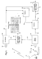
- a base station 10 located in a cell is shown together with a first receiver 20 and a second receiver 30.
- the first receiver 20 is positioned in the cell to have a direct line-of-sight with the base station 10 as indicated by arrow 'A'. Whilst it is necessary for the first receiver 20 to have a good quality communication link with the base station 10, this is not the case for the second receiver 30.
- Each receiver 20, 30 has a respective antenna 22, 32 for receiving signals from the base station 10.
- the good quality communication link can be achieved by using an elevated receiver, an antenna with direct gain, a line-of-sight propagation path, advanced signal processing techniques, other suitable methods, or combinations thereof.
- Each receiver 20, 30 is connected to a correlator 40 to correlate received signals 24, 34 therefrom.
- Output 42 from correlator 40 can be displayed as a plot of propagation delay against frequency shift for the received signals.
- An enlarged view of output 42 is shown in Figure 2 .
- crosses placed on the plot indicate signals that have been received and classified in terms of propagation delay, frequency shift, amplitude and phase relative to the first receiver signal.
- the replicator 50 creates a replica signal 52 based on a selection 44 ( Figure 2 ) made from the output 42.
- the replica signal 52 forms one input to a subtractor 60.
- the other input to the subtractor 60 is a second output 36 from the second receiver 30.
- the replica signal 52 is subtracted from the signals received at the second receiver 30 to provide subtracted output signal 62.
- Output signal 62 forms one of the inputs to a second correlator 70, the second output 26 from the first receiver 20 forming the second input.
- Correlator 70 is identical to correlator 40 and correlates signals from the first receiver 20, output 26, and the subtracted output signal 62 from the second receiver 30 to provide output 72.
- Output 72 can be displayed in a similar way to output 42 but, as shown in Figure 3 , only selection 74 corresponding to selection 44 of Figure 2 is enhanced. As a result, the selection 44 is enhanced.
- the output obtained can be tailored by the selection 44 ( Figure 2 ) and any other portion of the output 42 can be selected and used as the basis for the replica signal 52.
- the output 42 is shown in more detail.
- a number of signals 80 are present in the propagation delay/frequency shift domain. In this case, however, only signals 80' within selection 44 are of interest. Signals 80" are to be removed in the subsequent processing - these signals forming the basis of the replica signal 52. It will be appreciated that signals 80" may detract from the performance of the system.
- time delay correlation resolution is dependent on fundamental physical laws relating to the bandwidth and modulation characteristics of the signal in use and other factors such as system noise levels.
- the frequency resolution will essentially depend on the integration period applied during the received signal processing and other factors such as system noise levels.
- other resolution limits may be imposed in practice by such factors as the period over which the overall propagation and environmental conditions remain stable.
Landscapes
- Engineering & Computer Science (AREA)
- Computer Networks & Wireless Communication (AREA)
- Signal Processing (AREA)
- Physics & Mathematics (AREA)
- Electromagnetism (AREA)
- Mobile Radio Communication Systems (AREA)
- Noise Elimination (AREA)
- Monitoring And Testing Of Transmission In General (AREA)
- Radio Transmission System (AREA)
- Transforming Light Signals Into Electric Signals (AREA)
- Networks Using Active Elements (AREA)
- Gyroscopes (AREA)
- Surgical Instruments (AREA)
- Radar Systems Or Details Thereof (AREA)
- Investigating Or Analysing Materials By Optical Means (AREA)
- Circuits Of Receivers In General (AREA)
- Instruments For Measurement Of Length By Optical Means (AREA)
- Variable-Direction Aerials And Aerial Arrays (AREA)
- Picture Signal Circuits (AREA)
- Diaphragms For Electromechanical Transducers (AREA)
Abstract
Description
- The present invention relates to enhancing signals in a mobile telecommunications network.
- Base stations are adapted to operate in specific environments having local infrastructure, for example, buildings, and other environmental factors (including geographical features such as terrain and trees). The local infrastructure and environmental factors are known to give rise to perturbations in the transmission of signals. These perturbations can take the form of errors in the received signals, and signal degradation may occur during the transmission of any signals due to signal attenuation, multi-path reflection, multi-path dispersion, background noise or as a result of cross talk from adjacent cells. All these effects reduce the efficiency and performance of the telecommunications cell.
- In order to overcome these effects, it is useful to determine the propagation characteristics of a cell within a mobile telecommunications network so that compensation can be made for the specific environment of each cell in the network, for example, to enhance the signal-to-noise (S/N) ratio within that cell.
-
US-A-5 675 581 describes a method for simulating interference power received by a base station in a telecommunications network. A first composite signal power that corresponds to a sum of signal power transmitted by a first set of simulated users within a first cell is determined. A first normalised data rate for the first composite signal is also generated. The first composite signal power and the first normalised data rate are used to generate a first interference signal that is input to the base station receivers. A second composite signal power may also be determined from a sum of signal power transmitted by a second set of simulated users within cells outside of the first cell together with a second data rate for a second composite signal. The second composite signal and the second normalised data rate are used to generate a second interference signal that can be used to modify the first interference signal. - In accordance with one aspect of the present invention, there is provided a method of enhancing signals in a mobile telecommunications system, the system comprising a base station and first and second receivers within a reception zone of the base station, the method including:
- a) receiving a plurality of first signals at the first receiver, the first receiver having good quality communication link with the base station;
- b) receiving a plurality of second signals at the second receiver;
- c) correlating the received signals from both receivers to provide an estimated correlation therefor;
- d) selecting areas from within the estimated correlation;
- e) creating a replica of unwanted signals using said selection and said plurality of first signals; and
- f) enhancing said plurality of second signals by eliminating said replica therefrom.
- Preferably, the estimated correlation comprises a correlation of propagation delay and frequency shift for the received signals.
- Additionally, step f) includes correlating said enhanced plurality of second signals with said plurality of first signals to produce an enhanced correlation. The enhanced correlation may comprise a correlation of propagation delay and frequency shift for the enhanced plurality of second signals and the plurality of first signals.
- For a better understanding of the present invention, reference will now be made, by way of example only, to the accompanying drawings, in which:
-
Figure 1 illustrates a block diagram of a system for determining propagation characteristics in accordance with the present invention; -
Figure 2 illustrates an enlarged view of the output of the correlator shown inFigure 1 ; and -
Figure 3 is similar toFigure 2 but with the selection enhanced. - The present invention relies on correlation being made in both time and frequency domains between a plurality of signals received at a first and a second receiver from the same base station. These signals can be referred to as first receiver signals and second receiver signals. As both receiver signals tend to have good auto-correlation properties, that is, having a large main peak at zero relative delay and low side lobes elsewhere (not shown), it is possible to resolve components of the received signals in terms of their amplitudes, time delays, frequency shifts and phase shifts with respect to the first receiver signal. It is therefore possible to categorise unwanted signals in terms of relative time delay (propagation delay) and frequency shift. The signal components that fall into the unwanted category can be identified by their propagation delay and frequency shift characteristics, and good estimates with respect to the first receiver signal can be obtained. These estimates are then used in conjunction with the first receiver signal to create replica signals of the signals corresponding thereto. The replica signals are then subtracted from the second receiver signals to remove the unwanted signals. This has the effect of substantially reducing the unwanted signals so that a final correlation with the first receiver signal enhances the detection of the required signals.
- Referring now to
Figure 1 , abase station 10 located in a cell (not shown) is shown together with afirst receiver 20 and asecond receiver 30. Thefirst receiver 20 is positioned in the cell to have a direct line-of-sight with thebase station 10 as indicated by arrow 'A'. Whilst it is necessary for thefirst receiver 20 to have a good quality communication link with thebase station 10, this is not the case for thesecond receiver 30. Eachreceiver respective antenna base station 10. The good quality communication link can be achieved by using an elevated receiver, an antenna with direct gain, a line-of-sight propagation path, advanced signal processing techniques, other suitable methods, or combinations thereof. - Each
receiver correlator 40 to correlate receivedsignals 24, 34 therefrom.Output 42 fromcorrelator 40 can be displayed as a plot of propagation delay against frequency shift for the received signals. An enlarged view ofoutput 42 is shown inFigure 2 . - For illustrative purposes, crosses placed on the plot indicate signals that have been received and classified in terms of propagation delay, frequency shift, amplitude and phase relative to the first receiver signal.
- A
second output 26 from thefirst receiver 20, identical to output 24, is provided to areplicator 50 together withoutput 42. Thereplicator 50 creates areplica signal 52 based on a selection 44 (Figure 2 ) made from theoutput 42. Thereplica signal 52 forms one input to asubtractor 60. The other input to thesubtractor 60 is asecond output 36 from thesecond receiver 30. - In the
subtractor 60, thereplica signal 52 is subtracted from the signals received at thesecond receiver 30 to providesubtracted output signal 62.Output signal 62 forms one of the inputs to asecond correlator 70, thesecond output 26 from thefirst receiver 20 forming the second input. - Correlator 70 is identical to
correlator 40 and correlates signals from thefirst receiver 20,output 26, and thesubtracted output signal 62 from thesecond receiver 30 to provideoutput 72.Output 72 can be displayed in a similar way to output 42 but, as shown inFigure 3 , only selection 74 corresponding toselection 44 ofFigure 2 is enhanced. As a result, theselection 44 is enhanced. - Naturally, the output obtained can be tailored by the selection 44 (
Figure 2 ) and any other portion of theoutput 42 can be selected and used as the basis for thereplica signal 52. - In
Figure 2 , theoutput 42 is shown in more detail. Here, a number ofsignals 80 are present in the propagation delay/frequency shift domain. In this case, however, only signals 80' withinselection 44 are of interest.Signals 80" are to be removed in the subsequent processing - these signals forming the basis of thereplica signal 52. It will be appreciated thatsignals 80" may detract from the performance of the system. - In
Figure 3 , only signals 80' remain after correlation of theoutput 62 andsecond output 26 from the first receiver 20 (Figure 1 ). - It will be appreciated that the conceptual correlation processes in the time delay and frequency shift domains may be conveniently implemented in either the time or frequency signal processing domains, for example, by employing Fast Fourier Transform (FFT) processing as is well understood by those skilled in the art.
- It will also be appreciated that the time delay correlation resolution is dependent on fundamental physical laws relating to the bandwidth and modulation characteristics of the signal in use and other factors such as system noise levels. The frequency resolution will essentially depend on the integration period applied during the received signal processing and other factors such as system noise levels. In additions, it will be appreciated that other resolution limits may be imposed in practice by such factors as the period over which the overall propagation and environmental conditions remain stable.
Claims (4)
- A method of enhancing signals in a mobile telecommunications system (10, 20, 30), the system comprising a base station (10) and first and second receivers (20, 30) within a reception zone of the base station (10), the method including:a) receiving a plurality of first signals at the first receiver (20), the first receiver (20) having a good quality communications link with the base station (10);b) receiving a plurality of second signals at the second receiver (30);c) correlating the received signals from both receivers (20, 30) to provide an estimated correlation therefor;d) selecting areas from within the estimated correlation;e) creating a replica of unwanted signals using said selection and said plurality of first signals; andf) enhancing said plurality of second signals by eliminating said replica therefrom.
- A method according to claim 1, wherein the estimated correlation comprises a correlation of propagation delay and frequency shift for the received signals.
- A method according to claim 1 or 2, wherein step f) includes correlating said enhanced plurality of second signals with said plurality of first signals to produce an enhanced correlation.
- A method according to claim 3, wherein the enhanced correlation comprises a correlation of propagation delay and frequency shift for the enhanced plurality of second signals and the plurality of first signals.
Applications Claiming Priority (2)
| Application Number | Priority Date | Filing Date | Title |
|---|---|---|---|
| GBGB0327041.0A GB0327041D0 (en) | 2003-11-21 | 2003-11-21 | Apparatus and methods |
| PCT/GB2004/004905 WO2005053191A1 (en) | 2003-11-21 | 2004-11-19 | Enhancing signals |
Publications (2)
| Publication Number | Publication Date |
|---|---|
| EP1685665A1 EP1685665A1 (en) | 2006-08-02 |
| EP1685665B1 true EP1685665B1 (en) | 2010-10-27 |
Family
ID=29764162
Family Applications (5)
| Application Number | Title | Priority Date | Filing Date |
|---|---|---|---|
| EP04798608A Withdrawn EP1685623A1 (en) | 2003-11-21 | 2004-11-19 | Wideband antenna and receiver calibration |
| EP04798616A Not-in-force EP1685665B1 (en) | 2003-11-21 | 2004-11-19 | Enhancing signals |
| EP04798631.0A Not-in-force EP1685654B1 (en) | 2003-11-21 | 2004-11-19 | Suppression of unwanted signal elements by sinusoidal amplitude windowing |
| EP04798612A Not-in-force EP1685664B1 (en) | 2003-11-21 | 2004-11-19 | Signal interference measurement |
| EP04798621A Not-in-force EP1685653B1 (en) | 2003-11-21 | 2004-11-19 | Signal regeneration |
Family Applications Before (1)
| Application Number | Title | Priority Date | Filing Date |
|---|---|---|---|
| EP04798608A Withdrawn EP1685623A1 (en) | 2003-11-21 | 2004-11-19 | Wideband antenna and receiver calibration |
Family Applications After (3)
| Application Number | Title | Priority Date | Filing Date |
|---|---|---|---|
| EP04798631.0A Not-in-force EP1685654B1 (en) | 2003-11-21 | 2004-11-19 | Suppression of unwanted signal elements by sinusoidal amplitude windowing |
| EP04798612A Not-in-force EP1685664B1 (en) | 2003-11-21 | 2004-11-19 | Signal interference measurement |
| EP04798621A Not-in-force EP1685653B1 (en) | 2003-11-21 | 2004-11-19 | Signal regeneration |
Country Status (8)
| Country | Link |
|---|---|
| US (5) | US7606337B2 (en) |
| EP (5) | EP1685623A1 (en) |
| AT (3) | ATE476023T1 (en) |
| AU (5) | AU2004310544B2 (en) |
| DE (3) | DE602004028394D1 (en) |
| ES (4) | ES2286696T3 (en) |
| GB (1) | GB0327041D0 (en) |
| WO (5) | WO2005053190A1 (en) |
Families Citing this family (23)
| Publication number | Priority date | Publication date | Assignee | Title |
|---|---|---|---|---|
| US20070118361A1 (en) * | 2005-10-07 | 2007-05-24 | Deepen Sinha | Window apparatus and method |
| BRPI0617431B1 (en) * | 2005-11-16 | 2019-01-15 | Telefonaktiebolaget Lm Ericsson Publ Se | inspection system and method for evaluating antenna installations in a communication system |
| US8369809B2 (en) * | 2007-07-27 | 2013-02-05 | Netlogic Microsystems, Inc. | Crest factor reduction |
| EP2201402A1 (en) * | 2007-10-12 | 2010-06-30 | BAE Systems PLC | Receiver equalisation |
| WO2009151579A1 (en) * | 2008-06-11 | 2009-12-17 | Optichron, Inc. | Crest factor reduction with phase optimization |
| GB2467773B (en) * | 2009-02-13 | 2012-02-01 | Socowave Technologies Ltd | Communication system, apparatus and methods for calibrating an antenna array |
| JP5620757B2 (en) * | 2010-09-01 | 2014-11-05 | 株式会社豊田中央研究所 | Radar equipment |
| US20140370823A1 (en) * | 2011-10-21 | 2014-12-18 | Optis Cellular Technology, Llc | Methods, processing device, computer programs, computer program products, and antenna apparatus for calibration of antenna apparatus |
| CN106256044B (en) * | 2014-05-07 | 2019-11-12 | 华为技术有限公司 | A kind of phased array calibration method and phased array calibrate circuit |
| WO2016089143A1 (en) * | 2014-12-05 | 2016-06-09 | 엘지전자 주식회사 | Method for performing uplink transmission on subframe to which reduced cp is applied and user device |
| CN106450796B (en) * | 2016-09-07 | 2020-01-07 | 四川九洲电器集团有限责任公司 | Array antenna system and antenna calibration method |
| ES2895680T3 (en) * | 2017-11-07 | 2022-02-22 | Siemens Ag | Procedure for the synchronization of transmitting and receiving units in a multicarrier signal transmission |
| US10734721B2 (en) | 2017-11-13 | 2020-08-04 | Loon Llc | Beamforming calibration |
| EP3711199B1 (en) * | 2017-11-13 | 2022-10-19 | SoftBank Corp. | Beamforming calibration |
| US10320349B1 (en) | 2017-12-06 | 2019-06-11 | Space Systems/Loral, Llc | Multiport amplifier input network with compensation for output network gain and phase frequency response imbalance |
| US10284308B1 (en) | 2017-12-06 | 2019-05-07 | Space Systems/Loral, Llc | Satellite system calibration in active operational channels |
| US10361762B2 (en) | 2017-12-06 | 2019-07-23 | Space Systems/Loral, Llc | Calibration of satellite beamforming channels |
| US10218548B1 (en) | 2018-01-24 | 2019-02-26 | National Instruments Corporation | Wireless radio receiver that performs adaptive phase tracking |
| US10218549B1 (en) * | 2018-01-24 | 2019-02-26 | National Instruments Corporation | Wireless radio receiver that performs adaptive phase tracking |
| KR102457566B1 (en) * | 2018-02-22 | 2022-10-21 | 한국전자통신연구원 | Modem performing modulation or demodulation based on length of burst in a data packet and a method performed by the modem |
| US10782331B2 (en) * | 2018-06-21 | 2020-09-22 | Rohde & Schwarz Gmbh & Co. Kg | Power measurement apparatus |
| EP3790111B1 (en) | 2018-07-06 | 2022-03-02 | Huawei Technologies Co., Ltd. | Method for calibrating phased-array antenna, and related apparatus |
| JP7231828B2 (en) * | 2019-04-26 | 2023-03-02 | 日本電信電話株式会社 | INTERFERENCE WAVE CALCULATION METHOD, INTERFERENCE WAVE COMPUTER AND COMPUTER PROGRAM |
Family Cites Families (70)
| Publication number | Priority date | Publication date | Assignee | Title |
|---|---|---|---|---|
| US3754101A (en) * | 1971-07-02 | 1973-08-21 | Universal Signal Corp | Frequency rate communication system |
| DE2228069C3 (en) * | 1972-06-09 | 1979-07-26 | Philips Patentverwaltung Gmbh, 2000 Hamburg | Method and device for suppressing interference in frequency-modulated signals |
| JPS52136527A (en) * | 1976-05-10 | 1977-11-15 | Matsushita Electric Ind Co Ltd | Color demodulator |
| US4525676A (en) * | 1981-02-24 | 1985-06-25 | Nippon Electric Co., Ltd. | PSK Demodulation system having carrier frequency variation compensation |
| US4706174A (en) * | 1982-07-29 | 1987-11-10 | Eaton Corporation | Single phase to multiphase frequency multiplier |
| SE460086B (en) * | 1987-11-27 | 1989-09-04 | Ericsson Telefon Ab L M | DEVICE FOR CORRECTING THE FREQUENCY OF A COHERENT RECEIVER |
| US5109417A (en) * | 1989-01-27 | 1992-04-28 | Dolby Laboratories Licensing Corporation | Low bit rate transform coder, decoder, and encoder/decoder for high-quality audio |
| EP0581958A1 (en) * | 1991-04-22 | 1994-02-09 | Omron Corporation | Sealed electromagnetic relay |
| US5390216A (en) * | 1991-11-02 | 1995-02-14 | Robert Bosch Gmbh | Synchronization method for a mobile radiotelephone |
| US5287387A (en) * | 1992-03-06 | 1994-02-15 | Motorola, Inc. | Low splatter peak-to-average signal reduction |
| US5367257A (en) * | 1992-05-14 | 1994-11-22 | Garshelis Ivan J | Non-contact, magnetic sensor for determining direction of motion and velocity of a movable member |
| US5276706A (en) * | 1992-05-20 | 1994-01-04 | Hughes Aircraft Company | System and method for minimizing frequency offsets between digital communication stations |
| US5357257A (en) * | 1993-04-05 | 1994-10-18 | General Electric Company | Apparatus and method for equalizing channels in a multi-channel communication system |
| US5442593A (en) * | 1993-04-16 | 1995-08-15 | The Charles Stark Draper Laboratory, Inc. | Apparatus and method of nulling discrete frequency noise signals |
| US5490173A (en) * | 1993-07-02 | 1996-02-06 | Ford Motor Company | Multi-stage digital RF translator |
| FR2710805B1 (en) | 1993-09-29 | 1995-11-10 | Alcatel Mobile Comm France | Filling burst structure in a digital cellular radio system using the principle of TDMA, and base station for the development of such a structure. |
| JP3337795B2 (en) * | 1993-12-10 | 2002-10-21 | 富士通株式会社 | Relay device |
| US6157343A (en) * | 1996-09-09 | 2000-12-05 | Telefonaktiebolaget Lm Ericsson | Antenna array calibration |
| GB2291300B (en) | 1994-06-20 | 1997-12-17 | Motorola Ltd | Communications system |
| ZA955605B (en) * | 1994-07-13 | 1996-04-10 | Qualcomm Inc | System and method for simulating user interference received by subscriber units in a spread spectrum communication network |
| US5440265A (en) * | 1994-09-14 | 1995-08-08 | Sicom, Inc. | Differential/coherent digital demodulator operating at multiple symbol points |
| US5959580A (en) * | 1994-11-03 | 1999-09-28 | Ksi Inc. | Communications localization system |
| US6101399A (en) * | 1995-02-22 | 2000-08-08 | The Board Of Trustees Of The Leland Stanford Jr. University | Adaptive beam forming for transmitter operation in a wireless communication system |
| JP3272940B2 (en) * | 1996-03-07 | 2002-04-08 | ケイディーディーアイ株式会社 | Spread spectrum signal demodulator |
| GB2311697B (en) | 1996-03-22 | 1999-07-28 | Matsushita Electric Ind Co Ltd | Wireless communication system and method and system for detection of position of radio mobile station |
| US5974087A (en) | 1996-04-12 | 1999-10-26 | Advantest Corporation | Waveform quality measuring method and apparatus |
| US6047192A (en) * | 1996-05-13 | 2000-04-04 | Ksi Inc. | Robust, efficient, localization system |
| US5850218A (en) * | 1997-02-19 | 1998-12-15 | Time Warner Entertainment Company L.P. | Inter-active program guide with default selection control |
| US20030186725A1 (en) * | 1997-03-18 | 2003-10-02 | Matsushita Electric Industrial Co., Ltd. | Calibration apparatus for array antenna radio receiving apparatus |
| EP0938204A4 (en) * | 1997-03-18 | 2005-01-26 | Matsushita Electric Ind Co Ltd | Calibration device for array antenna wireless receiver |
| IT1293059B1 (en) | 1997-06-24 | 1999-02-11 | Space Engineering Spa | DIGITAL BI-STATIC RADAR WITH EXPANDED SPECTRUM |
| FR2766320B1 (en) * | 1997-07-15 | 1999-10-15 | Thomson Csf | METHOD AND DEVICE FOR ANALYZING INTERFERENCE IN A CELLULAR RADIO COMMUNICATION SYSTEM |
| EP1050115B1 (en) | 1998-01-22 | 2006-05-24 | BRITISH TELECOMMUNICATIONS public limited company | Receiving spread spectrum signals with narrowband interference |
| EP0964530A1 (en) * | 1998-06-05 | 1999-12-15 | Siemens Aktiengesellschaft | Radio communications receiver and interference cancellation method |
| US6577686B1 (en) * | 1998-10-13 | 2003-06-10 | Matsushita Electric Industrial Co., Ltd. | Receiver |
| EP0996238B1 (en) * | 1998-10-19 | 2003-05-02 | Lucent Technologies Inc. | Iterative timing estimation of GSM bursts |
| US6373878B1 (en) * | 1998-11-02 | 2002-04-16 | Telefonaktiebolaget Lm Ericsson (Publ) | Using a fast AGC as part of SIR calculation |
| US6240290B1 (en) * | 1999-03-04 | 2001-05-29 | Harris Corporation | Base station hand-off mechanism for cellular communication system |
| GB2347831B (en) * | 1999-03-06 | 2004-07-07 | Nec Technologies | Sychronisation in digital data transmission systems |
| DE60014790T2 (en) * | 1999-07-15 | 2006-02-09 | Mitsubishi Denki K.K. | Device for reducing noise |
| EP1085676B1 (en) * | 1999-09-16 | 2014-10-22 | Alcatel Lucent | Method of controlling power in a point to multipoint communication network and system for carrying out said method |
| WO2001028272A1 (en) | 1999-10-13 | 2001-04-19 | Koninklijke Kpn N.V. | Method and system for finding the position of mobile terminals |
| US6597730B1 (en) * | 1999-11-03 | 2003-07-22 | Northrop Grumman Corporation | Satellite communication array transceiver |
| JP3557969B2 (en) * | 1999-11-24 | 2004-08-25 | 日本電気株式会社 | Wireless receiver and calibration method |
| FR2802371B1 (en) * | 1999-12-10 | 2003-09-26 | Matra Nortel Communications | SIGNALING METHOD IN A RADIO COMMUNICATION SYSTEM, TRANSMITTERS, RECEIVERS AND REPEATERS FOR IMPLEMENTING THE METHOD |
| US6628735B1 (en) * | 1999-12-22 | 2003-09-30 | Thomson Licensing S.A. | Correction of a sampling frequency offset in an orthogonal frequency division multiplexing system |
| US7027424B1 (en) * | 2000-05-24 | 2006-04-11 | Vtech Communications, Ltd. | Method for avoiding interference in a digital communication system |
| JP3424659B2 (en) * | 2000-06-02 | 2003-07-07 | 日本電気株式会社 | Multi-beam receiver |
| JP4311528B2 (en) * | 2000-06-09 | 2009-08-12 | アウェア, インコーポレイテッド | System and method for multi-carrier transceiver with radio frequency interference reduction |
| US6931292B1 (en) * | 2000-06-19 | 2005-08-16 | Jabra Corporation | Noise reduction method and apparatus |
| KR100338661B1 (en) * | 2000-08-18 | 2002-07-13 | 윤종용 | Apparatus and method for managing dormant state in a wireless packet data system |
| EP1317831A2 (en) * | 2000-09-12 | 2003-06-11 | Siemens Aktiengesellschaft | Method and orthogonal frequency division multiplexing (ofdm) receiver for reducing the influence of harmonic interferences on ofdm transmission systems |
| US6369758B1 (en) * | 2000-11-01 | 2002-04-09 | Unique Broadband Systems, Inc. | Adaptive antenna array for mobile communication |
| US7035337B2 (en) * | 2000-11-29 | 2006-04-25 | Sony Corporation | Stream processing apparatus |
| AU2002237226A1 (en) | 2000-12-20 | 2002-07-01 | Telefonaktiebolaget Lm Ericsson (Publ) | Method and apparatus for classifying interference |
| JP2004526167A (en) | 2001-05-04 | 2004-08-26 | ロッキード・マーティン・コーポレイション | System and method for processing narrowband pre-detection signals for passive coherent search applications |
| US6741661B2 (en) * | 2001-05-22 | 2004-05-25 | Qualcomm Incorporated | Method and apparatus for peak-to-average power reduction |
| FI20011342A0 (en) * | 2001-06-25 | 2001-06-25 | Nokia Corp | Method and device for obtaining information |
| US6876859B2 (en) * | 2001-07-18 | 2005-04-05 | Trueposition, Inc. | Method for estimating TDOA and FDOA in a wireless location system |
| US6909277B2 (en) * | 2002-03-13 | 2005-06-21 | Caterpillar Inc | Amplification circuit for increasing variable reluctance sensor output |
| ES2198207B2 (en) * | 2002-04-12 | 2004-09-16 | Telefonica, S.A. | GSM REPEATER SYSTEM WITH SPECTRAL EXCHANGE BETWEEN GSM FREQUENCY BANDS OF 900 AND 1800 MHZ, AS WELL AS ACCESS METHOD. |
| US7158542B1 (en) * | 2002-05-03 | 2007-01-02 | Atheros Communications, Inc. | Dynamic preamble detection |
| US7013113B2 (en) * | 2002-07-25 | 2006-03-14 | Pctel Maryland, Inc. | Method and apparatus for co-channel interference measurements and interference component separation based on statistical signal processing in drive-test area |
| GB2395095A (en) * | 2002-10-30 | 2004-05-12 | Nokia Corp | Reducing noise in a multi-carrier signal |
| US7187736B2 (en) | 2003-02-13 | 2007-03-06 | Motorola Inc. | Reducing interference in a GSM communication system |
| US6954707B2 (en) * | 2003-02-18 | 2005-10-11 | Tektronix, Inc. | Multiple sinusoidal burst frequency measurements |
| KR100943272B1 (en) * | 2003-02-18 | 2010-02-23 | 삼성전자주식회사 | Digital communication system having channel estimation device and a method channel estimating thereof |
| US20050073947A1 (en) * | 2003-10-02 | 2005-04-07 | Texas Instruments Incorporated | Channel estimator for a receiver and method of operation thereof |
| US7796568B2 (en) * | 2003-12-18 | 2010-09-14 | Telefonaktiebolaget L M Ericsson (Publ) | Method and apparatus for determining the content of bursts to be transmitted from a base station |
| US7474718B2 (en) * | 2003-12-30 | 2009-01-06 | Nokia Corporation | Frequency control for a mobile communications device |
-
2003
- 2003-11-21 GB GBGB0327041.0A patent/GB0327041D0/en not_active Ceased
-
2004
- 2004-11-19 WO PCT/GB2004/004901 patent/WO2005053190A1/en not_active Application Discontinuation
- 2004-11-19 US US10/521,747 patent/US7606337B2/en active Active
- 2004-11-19 ES ES04798621T patent/ES2286696T3/en active Active
- 2004-11-19 WO PCT/GB2004/004921 patent/WO2005053175A1/en active Search and Examination
- 2004-11-19 DE DE602004028394T patent/DE602004028394D1/en active Active
- 2004-11-19 ES ES04798616T patent/ES2353080T3/en active Active
- 2004-11-19 AT AT04798612T patent/ATE476023T1/en not_active IP Right Cessation
- 2004-11-19 US US10/521,745 patent/US8085886B2/en not_active Expired - Fee Related
- 2004-11-19 AU AU2004310544A patent/AU2004310544B2/en not_active Ceased
- 2004-11-19 DE DE602004006530T patent/DE602004006530T2/en active Active
- 2004-11-19 ES ES04798631T patent/ES2435517T3/en active Active
- 2004-11-19 US US10/521,744 patent/US20050272392A1/en not_active Abandoned
- 2004-11-19 US US10/522,756 patent/US7894557B2/en not_active Expired - Fee Related
- 2004-11-19 EP EP04798608A patent/EP1685623A1/en not_active Withdrawn
- 2004-11-19 AT AT04798616T patent/ATE486418T1/en not_active IP Right Cessation
- 2004-11-19 US US10/522,757 patent/US7907684B2/en not_active Expired - Fee Related
- 2004-11-19 WO PCT/GB2004/004896 patent/WO2005053094A1/en not_active Application Discontinuation
- 2004-11-19 ES ES04798612T patent/ES2347932T3/en active Active
- 2004-11-19 AT AT04798621T patent/ATE362676T1/en not_active IP Right Cessation
- 2004-11-19 AU AU2004310534A patent/AU2004310534A1/en not_active Abandoned
- 2004-11-19 AU AU2004310536A patent/AU2004310536B2/en not_active Ceased
- 2004-11-19 WO PCT/GB2004/004910 patent/WO2005053174A1/en active IP Right Grant
- 2004-11-19 AU AU2004310537A patent/AU2004310537B2/en not_active Ceased
- 2004-11-19 EP EP04798616A patent/EP1685665B1/en not_active Not-in-force
- 2004-11-19 EP EP04798631.0A patent/EP1685654B1/en not_active Not-in-force
- 2004-11-19 EP EP04798612A patent/EP1685664B1/en not_active Not-in-force
- 2004-11-19 EP EP04798621A patent/EP1685653B1/en not_active Not-in-force
- 2004-11-19 WO PCT/GB2004/004905 patent/WO2005053191A1/en not_active Application Discontinuation
- 2004-11-19 AU AU2004310539A patent/AU2004310539B2/en not_active Ceased
- 2004-11-19 DE DE602004029808T patent/DE602004029808D1/en active Active
Also Published As
Similar Documents
| Publication | Publication Date | Title |
|---|---|---|
| EP1685665B1 (en) | Enhancing signals | |
| Suzuki | A statistical model for urban radio propogation | |
| US7680026B2 (en) | Method and apparatus for improving reception in wireless networks subjected to neighboring cells' interferences | |
| CN1072865C (en) | Method for eliminating multiple-access interference and mobile station | |
| KR100559070B1 (en) | Adaptive antenna array and method for control thereof | |
| EP0318686B1 (en) | TDMA Radio system employing BPSK synchronisation for QPSK signals subject to random phase variation and multipath fading | |
| JPH10512414A (en) | Method and apparatus for using full spectrum transmit power in a spread spectrum communication system for tracking individual received phase and energy | |
| KR19990036012A (en) | Adaptive despreader | |
| JP2001517399A (en) | Self-synchronous equalization method and system | |
| US20040042531A1 (en) | System and method for CDMA communications | |
| CN102904707A (en) | Training sequence for a radio communications system | |
| CN101682357B (en) | Improved frequency offset estimator | |
| CN1108028C (en) | Estimation of signal to interference ratio in a mobile communication system | |
| Bashkirov et al. | Method of advanced channel estimation in OFDM systems by regression technique | |
| Wittmann et al. | Impact of the power delay profile shape on the bit error rate in mobile radio systems | |
| EP2495899A1 (en) | Receiver and receiving method | |
| EP1197026A1 (en) | Method and apparatus for channel estimation with transmit diversity | |
| Zogg | Multipath delay spread in a hilly region at 210 MHz | |
| US6690713B1 (en) | Tracking loop for a code division multiple access (CDMA) system | |
| US20100128806A1 (en) | Method for planning a digital video broadcasting network | |
| Hieder | Improvement of Fading Channel Modeling Performance for Wireless Channel | |
| Pu et al. | Channel estimation in mobile wireless communication | |
| US20040214578A1 (en) | Co-channel interference suppresssion by estimating the time of arrival (toa) | |
| JP3337274B2 (en) | Mobile communication system | |
| Mohammed et al. | FM channel model development and its emulator |
Legal Events
| Date | Code | Title | Description |
|---|---|---|---|
| PUAI | Public reference made under article 153(3) epc to a published international application that has entered the european phase |
Free format text: ORIGINAL CODE: 0009012 |
|
| 17P | Request for examination filed |
Effective date: 20060518 |
|
| AK | Designated contracting states |
Kind code of ref document: A1 Designated state(s): AT BE BG CH CY CZ DE DK EE ES FI FR GB GR HU IE IS IT LI LU MC NL PL PT RO SE SI SK TR |
|
| DAX | Request for extension of the european patent (deleted) | ||
| 17Q | First examination report despatched |
Effective date: 20090804 |
|
| GRAP | Despatch of communication of intention to grant a patent |
Free format text: ORIGINAL CODE: EPIDOSNIGR1 |
|
| GRAS | Grant fee paid |
Free format text: ORIGINAL CODE: EPIDOSNIGR3 |
|
| GRAA | (expected) grant |
Free format text: ORIGINAL CODE: 0009210 |
|
| AK | Designated contracting states |
Kind code of ref document: B1 Designated state(s): AT BE BG CH CY CZ DE DK EE ES FI FR GB GR HU IE IS IT LI LU MC NL PL PT RO SE SI SK TR |
|
| REG | Reference to a national code |
Ref country code: GB Ref legal event code: FG4D |
|
| REG | Reference to a national code |
Ref country code: CH Ref legal event code: EP |
|
| REG | Reference to a national code |
Ref country code: IE Ref legal event code: FG4D |
|
| REF | Corresponds to: |
Ref document number: 602004029808 Country of ref document: DE Date of ref document: 20101209 Kind code of ref document: P |
|
| REG | Reference to a national code |
Ref country code: NL Ref legal event code: T3 |
|
| REG | Reference to a national code |
Ref country code: SE Ref legal event code: TRGR |
|
| REG | Reference to a national code |
Ref country code: ES Ref legal event code: FG2A Effective date: 20110215 |
|
| PG25 | Lapsed in a contracting state [announced via postgrant information from national office to epo] |
Ref country code: SI Free format text: LAPSE BECAUSE OF FAILURE TO SUBMIT A TRANSLATION OF THE DESCRIPTION OR TO PAY THE FEE WITHIN THE PRESCRIBED TIME-LIMIT Effective date: 20101027 Ref country code: BG Free format text: LAPSE BECAUSE OF FAILURE TO SUBMIT A TRANSLATION OF THE DESCRIPTION OR TO PAY THE FEE WITHIN THE PRESCRIBED TIME-LIMIT Effective date: 20110127 Ref country code: AT Free format text: LAPSE BECAUSE OF FAILURE TO SUBMIT A TRANSLATION OF THE DESCRIPTION OR TO PAY THE FEE WITHIN THE PRESCRIBED TIME-LIMIT Effective date: 20101027 Ref country code: IS Free format text: LAPSE BECAUSE OF FAILURE TO SUBMIT A TRANSLATION OF THE DESCRIPTION OR TO PAY THE FEE WITHIN THE PRESCRIBED TIME-LIMIT Effective date: 20110227 Ref country code: FI Free format text: LAPSE BECAUSE OF FAILURE TO SUBMIT A TRANSLATION OF THE DESCRIPTION OR TO PAY THE FEE WITHIN THE PRESCRIBED TIME-LIMIT Effective date: 20101027 Ref country code: PT Free format text: LAPSE BECAUSE OF FAILURE TO SUBMIT A TRANSLATION OF THE DESCRIPTION OR TO PAY THE FEE WITHIN THE PRESCRIBED TIME-LIMIT Effective date: 20110228 |
|
| PG25 | Lapsed in a contracting state [announced via postgrant information from national office to epo] |
Ref country code: MC Free format text: LAPSE BECAUSE OF NON-PAYMENT OF DUE FEES Effective date: 20101130 Ref country code: BE Free format text: LAPSE BECAUSE OF FAILURE TO SUBMIT A TRANSLATION OF THE DESCRIPTION OR TO PAY THE FEE WITHIN THE PRESCRIBED TIME-LIMIT Effective date: 20101027 Ref country code: GR Free format text: LAPSE BECAUSE OF FAILURE TO SUBMIT A TRANSLATION OF THE DESCRIPTION OR TO PAY THE FEE WITHIN THE PRESCRIBED TIME-LIMIT Effective date: 20110128 |
|
| REG | Reference to a national code |
Ref country code: CH Ref legal event code: PL |
|
| PG25 | Lapsed in a contracting state [announced via postgrant information from national office to epo] |
Ref country code: LI Free format text: LAPSE BECAUSE OF NON-PAYMENT OF DUE FEES Effective date: 20101130 Ref country code: EE Free format text: LAPSE BECAUSE OF FAILURE TO SUBMIT A TRANSLATION OF THE DESCRIPTION OR TO PAY THE FEE WITHIN THE PRESCRIBED TIME-LIMIT Effective date: 20101027 Ref country code: CH Free format text: LAPSE BECAUSE OF NON-PAYMENT OF DUE FEES Effective date: 20101130 Ref country code: CZ Free format text: LAPSE BECAUSE OF FAILURE TO SUBMIT A TRANSLATION OF THE DESCRIPTION OR TO PAY THE FEE WITHIN THE PRESCRIBED TIME-LIMIT Effective date: 20101027 |
|
| PG25 | Lapsed in a contracting state [announced via postgrant information from national office to epo] |
Ref country code: PL Free format text: LAPSE BECAUSE OF FAILURE TO SUBMIT A TRANSLATION OF THE DESCRIPTION OR TO PAY THE FEE WITHIN THE PRESCRIBED TIME-LIMIT Effective date: 20101027 Ref country code: DK Free format text: LAPSE BECAUSE OF FAILURE TO SUBMIT A TRANSLATION OF THE DESCRIPTION OR TO PAY THE FEE WITHIN THE PRESCRIBED TIME-LIMIT Effective date: 20101027 Ref country code: RO Free format text: LAPSE BECAUSE OF FAILURE TO SUBMIT A TRANSLATION OF THE DESCRIPTION OR TO PAY THE FEE WITHIN THE PRESCRIBED TIME-LIMIT Effective date: 20101027 Ref country code: SK Free format text: LAPSE BECAUSE OF FAILURE TO SUBMIT A TRANSLATION OF THE DESCRIPTION OR TO PAY THE FEE WITHIN THE PRESCRIBED TIME-LIMIT Effective date: 20101027 |
|
| PLBE | No opposition filed within time limit |
Free format text: ORIGINAL CODE: 0009261 |
|
| STAA | Information on the status of an ep patent application or granted ep patent |
Free format text: STATUS: NO OPPOSITION FILED WITHIN TIME LIMIT |
|
| 26N | No opposition filed |
Effective date: 20110728 |
|
| PG25 | Lapsed in a contracting state [announced via postgrant information from national office to epo] |
Ref country code: IE Free format text: LAPSE BECAUSE OF NON-PAYMENT OF DUE FEES Effective date: 20101119 |
|
| REG | Reference to a national code |
Ref country code: DE Ref legal event code: R097 Ref document number: 602004029808 Country of ref document: DE Effective date: 20110728 |
|
| PG25 | Lapsed in a contracting state [announced via postgrant information from national office to epo] |
Ref country code: CY Free format text: LAPSE BECAUSE OF FAILURE TO SUBMIT A TRANSLATION OF THE DESCRIPTION OR TO PAY THE FEE WITHIN THE PRESCRIBED TIME-LIMIT Effective date: 20101027 |
|
| PG25 | Lapsed in a contracting state [announced via postgrant information from national office to epo] |
Ref country code: HU Free format text: LAPSE BECAUSE OF FAILURE TO SUBMIT A TRANSLATION OF THE DESCRIPTION OR TO PAY THE FEE WITHIN THE PRESCRIBED TIME-LIMIT Effective date: 20110428 Ref country code: LU Free format text: LAPSE BECAUSE OF NON-PAYMENT OF DUE FEES Effective date: 20101119 |
|
| PG25 | Lapsed in a contracting state [announced via postgrant information from national office to epo] |
Ref country code: TR Free format text: LAPSE BECAUSE OF FAILURE TO SUBMIT A TRANSLATION OF THE DESCRIPTION OR TO PAY THE FEE WITHIN THE PRESCRIBED TIME-LIMIT Effective date: 20101027 |
|
| REG | Reference to a national code |
Ref country code: FR Ref legal event code: PLFP Year of fee payment: 12 |
|
| REG | Reference to a national code |
Ref country code: FR Ref legal event code: PLFP Year of fee payment: 13 |
|
| REG | Reference to a national code |
Ref country code: FR Ref legal event code: PLFP Year of fee payment: 14 |
|
| PGFP | Annual fee paid to national office [announced via postgrant information from national office to epo] |
Ref country code: NL Payment date: 20201126 Year of fee payment: 17 |
|
| PGFP | Annual fee paid to national office [announced via postgrant information from national office to epo] |
Ref country code: DE Payment date: 20201130 Year of fee payment: 17 Ref country code: IT Payment date: 20201120 Year of fee payment: 17 Ref country code: GB Payment date: 20201126 Year of fee payment: 17 Ref country code: FR Payment date: 20201126 Year of fee payment: 17 Ref country code: ES Payment date: 20201222 Year of fee payment: 17 Ref country code: SE Payment date: 20201123 Year of fee payment: 17 |
|
| REG | Reference to a national code |
Ref country code: DE Ref legal event code: R119 Ref document number: 602004029808 Country of ref document: DE |
|
| REG | Reference to a national code |
Ref country code: NL Ref legal event code: MM Effective date: 20211201 |
|
| GBPC | Gb: european patent ceased through non-payment of renewal fee |
Effective date: 20211119 |
|
| PG25 | Lapsed in a contracting state [announced via postgrant information from national office to epo] |
Ref country code: SE Free format text: LAPSE BECAUSE OF NON-PAYMENT OF DUE FEES Effective date: 20211120 |
|
| PG25 | Lapsed in a contracting state [announced via postgrant information from national office to epo] |
Ref country code: NL Free format text: LAPSE BECAUSE OF NON-PAYMENT OF DUE FEES Effective date: 20211201 |
|
| PG25 | Lapsed in a contracting state [announced via postgrant information from national office to epo] |
Ref country code: GB Free format text: LAPSE BECAUSE OF NON-PAYMENT OF DUE FEES Effective date: 20211119 Ref country code: DE Free format text: LAPSE BECAUSE OF NON-PAYMENT OF DUE FEES Effective date: 20220601 |
|
| PG25 | Lapsed in a contracting state [announced via postgrant information from national office to epo] |
Ref country code: FR Free format text: LAPSE BECAUSE OF NON-PAYMENT OF DUE FEES Effective date: 20211130 |
|
| PG25 | Lapsed in a contracting state [announced via postgrant information from national office to epo] |
Ref country code: IT Free format text: LAPSE BECAUSE OF NON-PAYMENT OF DUE FEES Effective date: 20211119 |
|
| REG | Reference to a national code |
Ref country code: ES Ref legal event code: FD2A Effective date: 20230213 |
|
| PG25 | Lapsed in a contracting state [announced via postgrant information from national office to epo] |
Ref country code: ES Free format text: LAPSE BECAUSE OF NON-PAYMENT OF DUE FEES Effective date: 20211120 |