EP1685965A1 - Liquid container, liquid ejection device and liquid container case - Google Patents
Liquid container, liquid ejection device and liquid container case Download PDFInfo
- Publication number
- EP1685965A1 EP1685965A1 EP06001966A EP06001966A EP1685965A1 EP 1685965 A1 EP1685965 A1 EP 1685965A1 EP 06001966 A EP06001966 A EP 06001966A EP 06001966 A EP06001966 A EP 06001966A EP 1685965 A1 EP1685965 A1 EP 1685965A1
- Authority
- EP
- European Patent Office
- Prior art keywords
- liquid
- liquid storing
- ink
- liquid container
- storing
- Prior art date
- Legal status (The legal status is an assumption and is not a legal conclusion. Google has not performed a legal analysis and makes no representation as to the accuracy of the status listed.)
- Granted
Links
Images


Classifications
-
- B—PERFORMING OPERATIONS; TRANSPORTING
- B41—PRINTING; LINING MACHINES; TYPEWRITERS; STAMPS
- B41J—TYPEWRITERS; SELECTIVE PRINTING MECHANISMS, i.e. MECHANISMS PRINTING OTHERWISE THAN FROM A FORME; CORRECTION OF TYPOGRAPHICAL ERRORS
- B41J2/00—Typewriters or selective printing mechanisms characterised by the printing or marking process for which they are designed
- B41J2/005—Typewriters or selective printing mechanisms characterised by the printing or marking process for which they are designed characterised by bringing liquid or particles selectively into contact with a printing material
- B41J2/01—Ink jet
- B41J2/17—Ink jet characterised by ink handling
- B41J2/175—Ink supply systems ; Circuit parts therefor
- B41J2/17503—Ink cartridges
- B41J2/17506—Refilling of the cartridge
- B41J2/17509—Whilst mounted in the printer
-
- G—PHYSICS
- G02—OPTICS
- G02F—OPTICAL DEVICES OR ARRANGEMENTS FOR THE CONTROL OF LIGHT BY MODIFICATION OF THE OPTICAL PROPERTIES OF THE MEDIA OF THE ELEMENTS INVOLVED THEREIN; NON-LINEAR OPTICS; FREQUENCY-CHANGING OF LIGHT; OPTICAL LOGIC ELEMENTS; OPTICAL ANALOGUE/DIGITAL CONVERTERS
- G02F1/00—Devices or arrangements for the control of the intensity, colour, phase, polarisation or direction of light arriving from an independent light source, e.g. switching, gating or modulating; Non-linear optics
- G02F1/01—Devices or arrangements for the control of the intensity, colour, phase, polarisation or direction of light arriving from an independent light source, e.g. switching, gating or modulating; Non-linear optics for the control of the intensity, phase, polarisation or colour
- G02F1/13—Devices or arrangements for the control of the intensity, colour, phase, polarisation or direction of light arriving from an independent light source, e.g. switching, gating or modulating; Non-linear optics for the control of the intensity, phase, polarisation or colour based on liquid crystals, e.g. single liquid crystal display cells
- G02F1/1303—Apparatus specially adapted to the manufacture of LCDs
-
- B—PERFORMING OPERATIONS; TRANSPORTING
- B41—PRINTING; LINING MACHINES; TYPEWRITERS; STAMPS
- B41J—TYPEWRITERS; SELECTIVE PRINTING MECHANISMS, i.e. MECHANISMS PRINTING OTHERWISE THAN FROM A FORME; CORRECTION OF TYPOGRAPHICAL ERRORS
- B41J2/00—Typewriters or selective printing mechanisms characterised by the printing or marking process for which they are designed
- B41J2/005—Typewriters or selective printing mechanisms characterised by the printing or marking process for which they are designed characterised by bringing liquid or particles selectively into contact with a printing material
- B41J2/01—Ink jet
- B41J2/17—Ink jet characterised by ink handling
- B41J2/175—Ink supply systems ; Circuit parts therefor
- B41J2/17503—Ink cartridges
- B41J2/17506—Refilling of the cartridge
-
- B—PERFORMING OPERATIONS; TRANSPORTING
- B41—PRINTING; LINING MACHINES; TYPEWRITERS; STAMPS
- B41J—TYPEWRITERS; SELECTIVE PRINTING MECHANISMS, i.e. MECHANISMS PRINTING OTHERWISE THAN FROM A FORME; CORRECTION OF TYPOGRAPHICAL ERRORS
- B41J2/00—Typewriters or selective printing mechanisms characterised by the printing or marking process for which they are designed
- B41J2/005—Typewriters or selective printing mechanisms characterised by the printing or marking process for which they are designed characterised by bringing liquid or particles selectively into contact with a printing material
- B41J2/01—Ink jet
- B41J2/17—Ink jet characterised by ink handling
- B41J2/175—Ink supply systems ; Circuit parts therefor
- B41J2/17503—Ink cartridges
- B41J2/17513—Inner structure
-
- B—PERFORMING OPERATIONS; TRANSPORTING
- B41—PRINTING; LINING MACHINES; TYPEWRITERS; STAMPS
- B41J—TYPEWRITERS; SELECTIVE PRINTING MECHANISMS, i.e. MECHANISMS PRINTING OTHERWISE THAN FROM A FORME; CORRECTION OF TYPOGRAPHICAL ERRORS
- B41J2/00—Typewriters or selective printing mechanisms characterised by the printing or marking process for which they are designed
- B41J2/005—Typewriters or selective printing mechanisms characterised by the printing or marking process for which they are designed characterised by bringing liquid or particles selectively into contact with a printing material
- B41J2/01—Ink jet
- B41J2/17—Ink jet characterised by ink handling
- B41J2/175—Ink supply systems ; Circuit parts therefor
- B41J2/17503—Ink cartridges
- B41J2/1752—Mounting within the printer
- B41J2/17523—Ink connection
-
- B—PERFORMING OPERATIONS; TRANSPORTING
- B41—PRINTING; LINING MACHINES; TYPEWRITERS; STAMPS
- B41J—TYPEWRITERS; SELECTIVE PRINTING MECHANISMS, i.e. MECHANISMS PRINTING OTHERWISE THAN FROM A FORME; CORRECTION OF TYPOGRAPHICAL ERRORS
- B41J2/00—Typewriters or selective printing mechanisms characterised by the printing or marking process for which they are designed
- B41J2/005—Typewriters or selective printing mechanisms characterised by the printing or marking process for which they are designed characterised by bringing liquid or particles selectively into contact with a printing material
- B41J2/01—Ink jet
- B41J2/17—Ink jet characterised by ink handling
- B41J2/175—Ink supply systems ; Circuit parts therefor
- B41J2/17503—Ink cartridges
- B41J2/17553—Outer structure
-
- G—PHYSICS
- G02—OPTICS
- G02F—OPTICAL DEVICES OR ARRANGEMENTS FOR THE CONTROL OF LIGHT BY MODIFICATION OF THE OPTICAL PROPERTIES OF THE MEDIA OF THE ELEMENTS INVOLVED THEREIN; NON-LINEAR OPTICS; FREQUENCY-CHANGING OF LIGHT; OPTICAL LOGIC ELEMENTS; OPTICAL ANALOGUE/DIGITAL CONVERTERS
- G02F1/00—Devices or arrangements for the control of the intensity, colour, phase, polarisation or direction of light arriving from an independent light source, e.g. switching, gating or modulating; Non-linear optics
- G02F1/01—Devices or arrangements for the control of the intensity, colour, phase, polarisation or direction of light arriving from an independent light source, e.g. switching, gating or modulating; Non-linear optics for the control of the intensity, phase, polarisation or colour
- G02F1/13—Devices or arrangements for the control of the intensity, colour, phase, polarisation or direction of light arriving from an independent light source, e.g. switching, gating or modulating; Non-linear optics for the control of the intensity, phase, polarisation or colour based on liquid crystals, e.g. single liquid crystal display cells
- G02F1/1306—Details
- G02F1/1309—Repairing; Testing
Definitions
- This invention relates to a liquid container, a liquid ejection device and a liquid container case.
- an ink jet printer As a liquid ejection device, an ink jet printer has been known, in which ink is ejected from a nozzle to perform printing.
- This type of printer has been provided with a recording head having a plurality of nozzles and a carriage having the recording head. With the reciprocating movement of the carriage, ink is ejected from the nozzles to perform printing.
- An ink cartridge storing ink supplied to the nozzles is provided in this type of printer as a replaceable liquid container.
- the ink cartridge used in the off carriage type is generally made up of an ink pack storing ink and a case for storing the ink pack.
- the ink pack is generally formed such that an outlet member having an ink outlet port is sandwiched between two sheets of laminated films, and the peripheries of the films are welded to each other.
- the case is formed of plastics or the like, and stores the ink pack with the outlet member projected outward (as disclosed, for example, in JP-A-2002-120382 and JP-A-2000-296626). As indicated in JP-A-2002-120382, generally one ink pack is stored in one case.
- the ink cartridges are arranged corresponding to the number of the colors. Consequently, in the printer including ink of two or more colors, the space for providing the ink cartridges cannot be reduced, so it is difficult to reduce the size.
- the ink pack disclosed in JP-A-2000-296626 is so constructed that a plurality of storing parts are defined by welding two sheets of films and ink of different colors is stored in the respective storing parts.
- the intervals of the respective storing parts storing ink of the respective colors are determined depending on the size of the welded part. Consequently, it is difficult to further reduce the size of the ink cartridge. Since the ink of different colors is stored in one ink pack, when ink of a specified color is consumed, it is impossible to replace only the ink of that color, and the whole ink pack needs to be replaced. Therefore, the ink stored in the ink pack cannot be used effectively.
- the invention has been made in the light of such circumstances and provides a liquid container, a liquid ejection device and a liquid container case, which may effectively use a liquid stored in the liquid container and may be reduced in size in simple constitution.
- a liquid container includes: a plurality of liquid storing bags, each having a liquid outlet member provided with a liquid outlet port and a liquid storing part formed of flexible film material; and a liquid container case having support parts for fixing the liquid outlet members to expose the liquid outlet ports to the outside. At least four liquid storing bags are disposed to be shifted from each other with a part of the liquid storing bag overlapping a part of the adjacent liquid storing bag along the base of the liquid container case in the interior of the liquid container case. The space between the adjacent liquid outlet ports is gradually increased as it goes from the end in the arranging direction of the liquid outlet ports toward the center.
- the interior of the liquid container case can be efficiently utilized by partially overlapping arrangement of the liquid storing bags. That is, the liquid storing bags are accommodated in the liquid container case with a part of the liquid storing bag overlapping a part of the adjacent liquid storing bag. Accordingly, the liquid container can be reduced in size for that overlapping part of the liquid storing bags. Moreover, the space between the adjacent liquid outlet ports is gradually increased as it goes from the ends in the arranging direction of the liquid outlet ports toward the center, whereby the pressure applied to the adjacent liquid storing bag by each liquid storing bag can be made uniform regardless of the position of the liquid storing bag in the liquid container. As a result, the liquid stored in each liquid storing bag can be used effectively.
- a liquid container includes: a plurality of liquid storing bags, each having a liquid outlet member provided with a liquid outlet port and a liquid storing part formed of flexible film material; and a liquid container case having a case body provided with a base, a side wall interesting the base, support parts formed on the side wall for fixing the liquid outlet members to expose the liquid outlet ports to the outside, and an open face opposite to the base, and a lid member for sealing the open face.
- At least four liquid storing bags are disposed to be shifted from each other with a part of the liquid storing bag overlapping a part of the adjacent liquid storing bag along the base of the liquid container case. The space between the adjacent liquid outlet ports is gradually increased as it goes from the ends in the arranging direction of the liquid outlet ports toward the center.
- the liquid storing bags are accommodated in the liquid container case with a part of the liquid storing bag overlapping a part of the adjacent liquid storing bag. Accordingly, the liquid container can be reduced in size for that overlapping part of the liquid storing bags. Moreover, in the liquid container case including the lid member sealing the open face, the space between the adjacent liquid outlet ports is gradually increased as it goes from the ends in the arranging direction of the liquid outlet ports toward the center. Thus, the pressure of each liquid storing bag applied to the adjacent liquid storing bag can be made uniform regardless of the position of the liquid storing bag in the liquid container. As a result, the liquid stored in each liquid storing bag can be effectively used.
- each of the liquid storing bags is formed by welding four sides of two sheets of flexible films. Therefore, when the liquid is stored in the bag, the liquid storing bag is shaped like a spindle so that the central parts of the flexible films are most expanded. That is, the space between the thus formed liquid storing bag and the liquid container case near the ends of the flexible films approximates to the shape of the ends of the flexible films of the liquid storing bag. Therefore, in the space between the liquid storing bag and the liquid container case, a larger part of the adjacent liquid storing bag is positioned so that an overlap of the liquid storing bag and the adjacent liquid storing bag is increased to more effectively use the space of the liquid container case. Accordingly, the liquid container can be reduced in size, which will contribute to further reduction of size of a liquid ejection device including the liquid container.
- the liquid container case is provided with support parts for supporting the liquid storing bags so that the central axes of the liquid outlet ports are all disposed on the same horizontal plane.
- the respective liquid storing bags have the same liquid level. Accordingly, the pressure head depending on the height of the liquid level of the liquid storing bag is uniform so that the liquids supplied from the respective liquid storing bags can have the substantially same pressure.
- the overlapping parts of the liquid storing bags include the mutually welding parts of the flexible films.
- the mutually welding parts of the flexible films of the liquid storing bag that is, the parts storing no liquid overlap the adjacent liquid storing bag in the liquid container. Accordingly, even if the liquid storing bag is rotated, the liquid storing bag causes less influence upon the adjacent liquid storing bag. Therefore, the liquid in the liquid storing bag can be almost always supplied at-designated pressure.
- a plurality of liquid storing bags are accommodated at a designated angle of inclination to the base of the liquid container case.
- the plurality of liquid storing bags are accommodated at a designated angle of inclination, whereby in the space produced between the liquid storing bag and the liquid container case, the adjacent liquid storing bag can be easily disposed.
- the spaces which are generally produced between the liquid storing bag and the liquid container case on both sides (upper and lower sides) of the end of the liquid storing bag, can be combined as one large space by inclining the liquid storing bag. Accordingly, when the adjacent liquid storing bag is disposed in the larger space, an overlapping part between the liquid storing bag and the adjacent liquid storing bag can be enlarged so that the space in the liquid container case can be used further effectively.
- the liquid container case is provided with an attitude holding member adapted to hold the liquid storing bag in an attitude of being inclined at a designated angle.
- the liquid storing bag can be held in an attitude of being inclined at a designated angle by the attitude holding member.
- the attitude holding member in the liquid container, is formed integral with the liquid container case.
- the attitude holding member is formed integral with,the liquid container case, whereby the number of parts can be reduced to be inexpensive, and the attitude holding member can be always put in a designated position not to be moved. Accordingly, the liquid storing bag can be easily disposed in the liquid container.
- a reverse insertion preventing member and/or an erroneous insertion preventing member in the liquid container, prevents the liquid container from being mounted in an attitude other than a designated attitude to a liquid ejection device for ejecting a liquid in the liquid storing bags from a liquid ejection head.
- the erroneous insertion preventing member prevents the liquid container frombeing inserted into an improper liquid ejection device not having a designated shape.
- the reverse insertion preventing member is provided to thereby prevent the liquid storing bag from being mounted in the liquid ejection device in an attitude other than a designated attitude.
- the erroneous insertion preventing member is provided, whereby the liquid container having liquid storing bags storing liquid suitable for the liquid ejection device can only be mounted on the liquid ejection device. Accordingly, the liquid container cannot be mounted in a erroneous attitude on the liquid ejection device, and the liquid container not suitable for the liquid ejection device can not be mounted on the liquid ejection device, so that a designated liquid can be supplied to a designated portion of the liquid ejection device to more surely eject the designated liquid from the liquid ejection device.
- the reverse insertion preventing member and/or the erroneous insertion preventing member is provided on the liquid container case.
- the reverse insertion preventing member and/or the erroneous insertion preventing member is provided between the liquid outlet port of the liquid storing bag disposed closest to the wall surface of the plurality of liquid storing bags and the wall surface, whereby even if the reverse insertion preventing member and/or the erroneous insertion preventing member is provided, the liquid container will not be increased in size.
- the reverse insertion preventing member and/or the erroneous insertion preventing member is provided on the liquid container case between the liquid outlet port of the liquid storing bag disposed at the outermost end of the plurality of liquid storing bags and one wall surface of the liquid container case intersecting the base.
- the reverse insertion preventing member and/or the erroneous insertion preventing member is provided on the liquid container case between the liquid outlet port of the liquid storing bag disposed on the most one wall surface side of the plurality of liquid storing bags and the above one wall surface of the liquid container case intersecting the base, whereby even if the reverse insertion preventing member and/or the erroneous insertion preventing member is provided, the liquid container will not be increased in size.
- the liquid container includes a circuit board having a storing part storing the information regarding the liquid container, and the circuit board is provided on the liquid container case between the liquid outlet port of the liquid storing bag disposed at the outermost end of the plurality of liquid storing bags and one wall surface of the liquid container case intersecting the base.
- the space of the liquid container case is effectively used to form a small-sized liquid container case.
- the reverse insertion preventing member and/or the erroneous insertion preventing member, and the circuit board are provided on the liquid container case between the liquid outlet port of the liquid storing bag disposed at the outermost end of the plurality of liquid storing bags and one wall surface of the liquid container case intersecting the base.
- the reverse insertion preventing member and/or the erroneous insertion preventing member and the circuit board are both or all provided, whereby the necessary functions can be collected efficiently in a compact in the liquid container case without any influence upon the liquid storing bags in the inside thereof.
- the liquid storing bag in the liquid container, is provided with an information indicating member having information regarding the liquid to confirm the liquid information regarding the liquid stored in the liquid storing bag with the liquid storing bag put in the liquid container case.
- the liquid information regarding the liquid can be confirmed with the liquid storing bags accommodated in the liquid container case, whereby before the liquid container is mounted on the liquid ejection device, it can be confirmed whether or not a designated liquid storing bag is put in the liquid container certainly. Accordingly, there is less possibility of storing liquid other than a designated liquid in the liquid container by mistake.
- the liquid ejection device includes an accommodation part for accommodating the liquid container.
- the liquid container is reduced in size, so that the liquid ejection device including the accommodation part for accommodating the liquid container can be reduced in size.
- the space between the adjacent liquid outlet ports is gradually increased as it goes from the ends in the arranging direction of the liquid outlet ports toward the center, whereby the liquid stored in the liquid container can be used effectively.
- a liquid container case is adapted to store a plurality of liquid storing bags, each having an outlet member having a liquid outlet port and being attached to a flexible film, and the liquid container case is provided with a plurality of support parts for supporting the outlet members to store the liquid storing bags with a part of the liquid storing bag overlapping a part of the adjacent liquid storing bag.
- the space required for accommodating the liquid storing bag having the same volume as the conventional one can be reduced so that the liquid container case can be reduced in size to reduce the size of the liquid container.
- an ink cartridge 11 serving as a liquid container is substantially like a rectangular parallelepiped.
- the ink cartridge 11, as shown in Fig. 4, includes a plurality of ink packs 12 serving as liquid storing bags and a container case 13 for storing the ink packs.
- the ink pack 12 is, as shown in Fig. 7, made up of an ink outlet member 15 and a bag part 16.
- the ink outlet member 15 is substantially cylindrical, and the inside thereof is provided with an ink supply port 15a.
- the ink stored in the ink pack 12 is taken out through the ink supply port 15a.
- an annular groove 15b and an annular projection 15c provided adjacent to the groove 15b are formed in the substantially central area of the outer peripheral surface of the ink outlet member 15.
- the ink supply port 15a is provided with a valve mechanism not shown, which is opened only when the ink is supplied, thereby preventing ink in the bag part 16 from leaking out.
- the bag part 16 as a liquid storing part is formed of flexible material.
- two sheets of laminated films each obtained by depositing aluminum on a polyethylene film having gas barrier property can be preferably used, and four sides of the laminated films are welded by heat to form the bag part.
- two sheets of laminated films are superposed one on the other, and welded by heat taking three sides of the laminated films as welding parts 16a, 16b, 16d.
- the remaining one side is taken as a welding part 16d and welded by heat with the ink outlet member 15 projected from the center thereof to form a bag-like shape.
- the ink pack 12 is formed like a soft case (the so-called pillow type), and ink is sealingly stored in the enclosed state in the interior thereof.
- the ink packs 12 in the present embodiment respectively have the same outline shape and the same ink storing capacity, and the ink packs are filled with the same fill quantity of ink.
- a label 17 as an information indicating member is stuck to the upper surface of the bag part 16.
- the label 17 bears the information (corresponding to liquid information) on the quantity, color of the stored ink, or whether it is a dye or a pigment.
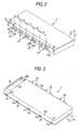
- the container case 13 is, as shown in Figs. 2 and 4, provided with a case body part 21 for accommodating the ink packs 12, and a lid case 22.
- the case body part 21 is, as shown in Figs. 2 and 3, a substantially box-shaped case provided with a base S (see Fig. 5) and a front face 13a as a sidewall intersecting the base S, and opened on the opposite side to the base S. The opening part is sealingly closed by the lid case 22.
- the case body part 21 is formed of non-flexible hard material.
- the lid case 22 in the present embodiment is formed of non-flexible hard material similarly to the case body part 21.
- the front face 13a of the container case 13 is provided with support parts 23 for fixing the respective ink outlet members 15 to expose the ink supply ports 15a of the ink packs 12 to the outside.
- the support parts 23 are provided for the same number as the number of stored ink packs 12, that is, six in the present embodiment.
- the support parts 23 are disposed along a straight line L1 (See Fig. 4) parallel to the base S and the front face 13a of the container case 13.
- the support parts 23 are provided in the substantially central area of the case body part 21.
- Each of the support parts 23 includes a lower support part 23a constituting the lower half, which is mounted on the case body part 21, and an upper support part 23b constituting the upper half, which is mounted on the lid case 22.
- the lid case 22 when the lid case 22 is attached to the case body part 21 with the ink outlet member 15 of the ink pack 12 supported on the lower support part 23a of the case body part 21, the lower and upper support parts 23a, 23b are aligned with each other to form the support part 23, thereby supporting and fixing the ink outlet member 15 of the ink pack 12.
- the lower support part 23a is provided with a semi-circular arc-like projection 24 and a semi-circular arc-like groove 25, and these are respectively engaged with the groove 15b and the projection 15c of the ink outlet member 15.
- the upper support part 23b is, similarly to the lower support part 23a, provided with a projection not shown and a groove not shown. Accordingly, when the ink outlet member 15 of the ink pack 12 fits into the lower and upper support parts 23a, 23b, the ink pack 12 is put in the ink cartridge 11 without moving longitudinally and laterally.
- the support parts 23 are provided in such positions that when the support parts 23 are respectively engaged with the ink outlet members 15, the ink packs 12 are disposed with a part of one of the ink packs 12 overlapping a part of adjacent one of the ink packs 12.
- the spaces A, B, C between the support parts 23 are gradually decreased as it goes toward the ends, so that the spaces A at both ends are smaller than the spaces B rather closer to the center, and the spaces B are smaller than the central space C. That is, the respective support parts 23 are provided so that the space between the adjacent liquid outlet members 15 is gradually increased as it goes from the ends in the arranging direction of the liquid outlet members toward the center. It was found from the tests that when the spaces A, B, C are thus set, the pressure of ink delivered from the respective ink packs 12 becomes more uniform. The reason for this is that as in the present embodiment, when the ink packs 12 are superposed as shown in Fig.
- the pressure of the ink packs 12 at the ends exerts an influence upon the pressure of the ink pack 12 located rather closer to the center. It is considered that the ink pack 12 disposed in the center is more influenced by the pressure of the adjacent ink pack 12 than that at the end. As a result, the pressure of the ink pack 12 applied to the adjacent ink pack 12 becomes substantially uniform regardless of the position of the ink pack 12 in the case body part 21.
- the front face 13a of the case body part 21 is provided with positioning holes 26 near both end parts thereof.
- the inside of the case body 21 is provided with three ribs 27 disposed parallel to the front face 13a on the left side as attitude determination means for determining the attitude of the ink pack 12. Accordingly, as shown in Fig. 6, the leftmost ink pack 12 put in the container case 13 is disposed along the ribs 27.
- the ink pack 12 holds the attitude of inclination at an angle ⁇ ( ⁇ 15° in the present embodiment) to the straight line L1 (and the base S of the container case 13) connecting the respective support parts 23.
- the support part 23 is provided in a position substantially half of the height of the case body part 21, the ink pack 12, in the attitude of inclination at an angle ⁇ , has its welding part 16a abutting on the lid case 22 and its welding part 16c abutting on the base S of the case body part 21.
- the lower surface 13c of the case body part 21 is provided with a groove 28 as a reverse insertion preventing member.
- the groove 28 is preferably located close to one wall surface M intersecting the base S, and below the ribs 27.
- the groove 28 is formed utilizing the space where the ink pack 12 is not disposed, which is formed between the ink outlet member 15 of the ink pack 12 disposed closest to the wall surface M of six ink packs 12 and the wall surface M.
- the formation of the groove 28 is extended from the front face 13a toward the back face 13b and ended on this side of the back 13b.
- the front face 13a is shaped so that the groove 28 is additionally formed in a substantially rectangular shape, whereas the back face 13b is simply formed in a substantially rectangular shape (See Fig. 1), That is, the front face 13a and the back 13b are different in shape.
- the back face 13b of the case body part 21 is provided with engagement holes 29 for engagement with the lid case 22.
- the groove 28 is provided with two projections 28a projected downward as an erroneous insertion preventing member.
- engaging projection parts 31 are formed on the lid case 22, and each of the engaging projection parts 31 is provided with a projection 31a projected toward the back face 13b.
- the projection part 31a is engaged with the corresponding engagement hole 29 of the case body part 21, thereby integrally fixing the lid case 22 to the case body part 21.
- the lid case 22 is provided with three ribs 32 formed on the right side as an attitude fixing member for fixing the attitude of the ink pack 12.
- the ribs 32 have the same shape as the ribs 27 of the case body part 21 to thereby hold the ink pack 12 put in the rightmost side in an attitude of inclination at a designated angle ⁇ .
- a printer body 40 is provided with a carriage 41 reciprocating in the direction of an arrow X.
- the lower surface of the carriage 41 is provided with a recording head 42 as a liquid ejection head having a plurality of nozzles.
- a cartridge mounting part 43 is provided on one side of the front face of the printer body 40.
- the insertion opening 43a is substantially like a rectangular parallelepiped, and provided with a projecting part 44 projected into the insertion opening 43a.
- the projecting part 44 is fitted to the groove 28 formed on the case body part 21 of the ink cartridge 11. Grooves 44a are formed on the upper surface of the projecting part 44.
- the groove 44a is fitted to the respective projection 28a of the groove 28 of the ink cartridge 11.
- the cartridge 11 is mounted in the printer body 40. Only in the case where the shapes of the grooves 44a provided in the projecting part 44 and the projections 28a conform to each other, the ink cartridge 11 is mounted in the printer body 40.
- the cartridge mounting part 43 of the printer body 40 is provided with a plurality of supply needles 45 disposed opposite to the ink cartridge 11.
- the respective supply needles 45 are disposed so that when the ink cartridge 11 is mounted on the ink cartridge mounting part 43, the respective supply needles 45 are positioned in the centers of the respective support parts 23 of the ink cartridge 11, that is, to be inserted in the respective ink supply ports 15a of the ink packs 12. Accordingly, when the ink cartridge 11 is mounted on the cartridge mounting part 43, ink in each ink pack 12 is supplied to the recording head 42 through a corresponding supply tube 46 and ejected from the recording head 42 toward the paper P.
- a pair of positioning members 47 are provided on both sides of the cartridge mounting part 43, i.e. regions outside a region where the supply needles 45 are disposed.
- the positioning members 47 are respectively fitted in the holes 26 of the case body part 21 to thereby fix the position of the ink cartridge 11.
- the positioning members 47 are formed longer than the supply needles 45, whereby positioning can be performed before the supply needles 45 are inserted in the ink supply ports 15a so as to surely achieve smooth insertion of the supply needles 45 into the ink supply ports 15a.
- an ink pack 12 storing ink of Cyan color is mounted on the leftmost side of the case body part 21. That is, with the ink pack 12 fitted in the lower side support part 23a on the leftmost side of the case body part 21, the ink pack 12 is mounted on the case body part 21.
- the ink pack 12 is put in the attitude of inclination at a designated angle ⁇ .
- the label 17 is seen on the upper part of the ink cartridge 11.
- the ink pack 12 storing ink of light Cyan color is put in the case body part 21, with the ink outlet member 15 engaged with the second lower support port 23a from the left.
- the ink pack 12 is inclined to take the substantially same attitude as the previously stored ink pack 12.
- the welding part 16a which is the end of the inserted ink pack 12
- the respective inkpacks 12 are disposed so that the substantially half of the ink pack 12 overlaps about the half of the adjacent ink pack 12.
- the label 17 of the previously stored ink pack 12 can be seen without being hidden.
- an ink pack 12 storing ink of Magenta color is inserted with the ink outlet member 15 of the ink pack 12 supported on the third lower support part 23a from the left.
- an ink pack 12 storing ink of light Magenta color is inserted with the ink outlet member 15 of the ink pack 12 supported on the fourth lower support part 23a from the left.
- an ink pack 12 storing ink of yellow color is inserted on the fifth one from the left, and finally, as shown in Fig. 4, an ink pack 12 storing ink of black color is inserted on the rightmost side.
- the labels 17 of the respective ink packs 12 are arranged on the upper surface side by side. According to the labels 17, it is visually confirmed whether or not the six ink packs 12 different in kind are stored in the ink cartridge 11.
- the engaging projection parts 31 of the lid case 22 are engaged with the engagement holes 29 of the case body part 21, and the case body part 21 is fitted to the lid case 22 to cover the opening of the case body part 21.
- the respective ink packs 12 are, as shown in Fig. 6, stored and held by the lid case 22.
- the ribs 32 of the lid case 22 are located on the right upper part of the ink pack 12 at the right end. Accordingly, the attitude of the rightmost ink pack 12 is held.
- the lid case 22 is thus fitted to the case body part 21 to assemble the ink cartridge 11 as shown in Figs. 2 and 3.
- the ink cartridge 11 is, as shown in Fig. 1, inserted in the insertion opening 43a of the cartridge mounting part 43 with the groove 28 opposite to the projection 44 and with the front face 13a opposite to the printer body 40. Since the shape of the back face 13b is different from the shape of the front face 13a, in the longitudinally reverse attitude where the back face 13b confronts with the printer body 40, the ink cartridge 11 cannot be mounted on the cartridge mounting part 43. Also in the case of the inverted attitude in which the groove 28 is not opposite to the projecting part 44, the ink cartridge 11 cannot be mounted on the cartridge mounting part 43. Further, when there is no conformity in the shape of the projections 28a and the grooves 44a, the ink cartridge 11 cannot be mounted in the printer body 40.
- the positioning members 47 of the printer body 40 are fitted in the holes 26 to thereby fix the position of the ink cartridge 11.
- the supply needles 45 of the cartridge mounting part 43 are inserted in the centers of the respective support parts 23 of the ink cartridge 11, that is, in the ink support ports 15a of the ink pack 12, and the valve mechanism in each of the ink supply port 15a opens the valve.
- ink can be supplied from each ink pack 12 of the ink cartridge 11 through the corresponding ink supply needle 45 and supply tube 46 to the recording head 42 of the carriage 41. Ink is ejected from the nozzles of the recording head 42 toward the paper P to perform printing.
- the ink cartridge 11 of the present embodiment will produce the following effects.
- the space of the ink cartridge 11 is effectively used to form a small-sized ink cartridge.
- the ink cartridge is formed with two projections 28a as the erroneous insertion preventing member, whereby more efficient and necessary functions can be collected in a compact without any influence on the inner ink packs 12.
- the plurality of liquid storing bags are accommodated at a designated angle of inclination to the liquid container case shaped substantially like a rectangular parallelepiped, whereby the adjacent liquid storing bag can be easily disposed in the space produced between the liquid storing bag and the liquid container case. Accordingly, the liquid storing bags are disposed at good volume efficiency in the liquid container case to reduce the size of the liquid container. Further, since the liquid container can be reduced in size, a liquid ejection device in which the liquid container is mounted can be reduced in size. Since the plurality of liquid storing bags are put in one liquid container case, only the liquid storing bag of a specified liquid can be easily replaced so that the liquid stored in the l'iquid container can be effectively used.
- the invention will be more apparent from the following preferred embodiments given in the paragraphs below.
Abstract
Description
- This invention relates to a liquid container, a liquid ejection device and a liquid container case.
- As a liquid ejection device, an ink jet printer has been known, in which ink is ejected from a nozzle to perform printing. This type of printer has been provided with a recording head having a plurality of nozzles and a carriage having the recording head. With the reciprocating movement of the carriage, ink is ejected from the nozzles to perform printing. An ink cartridge storing ink supplied to the nozzles is provided in this type of printer as a replaceable liquid container.
- In the case of the printer for printing a large-sized paper sheet, a large quantity of ink is used, so an ink cartridge storing a large volume of ink is needed. When such an ink cartridge is mounted on a carriage and moved, a great deal of load is applied to a driving part. Therefore, in the printer for printing a large-sized paper sheet, the ink cartridge has not been mounted on the carriage (the constitution is the so-called off carriage type).
- The ink cartridge used in the off carriage type is generally made up of an ink pack storing ink and a case for storing the ink pack. In more detail,, the ink pack is generally formed such that an outlet member having an ink outlet port is sandwiched between two sheets of laminated films, and the peripheries of the films are welded to each other. The case is formed of plastics or the like, and stores the ink pack with the outlet member projected outward (as disclosed, for example, in JP-A-2002-120382 and JP-A-2000-296626). As indicated in JP-A-2002-120382, generally one ink pack is stored in one case. Therefore, in the printer including ink of two or more colors, the ink cartridges are arranged corresponding to the number of the colors. Consequently, in the printer including ink of two or more colors, the space for providing the ink cartridges cannot be reduced, so it is difficult to reduce the size.
- On the other hand, in the ink cartridge disclosed in JP-A-2000-296626, one ink pack having a plurality of storing parts, each for storing ink is accommodated in one case. In more detail, the ink pack disclosed in JP-A-2000-296626 is so constructed that a plurality of storing parts are defined by welding two sheets of films and ink of different colors is stored in the respective storing parts.
- In the ink cartridge of JP-A-2000-296626, however, the intervals of the respective storing parts storing ink of the respective colors are determined depending on the size of the welded part. Consequently, it is difficult to further reduce the size of the ink cartridge. Since the ink of different colors is stored in one ink pack, when ink of a specified color is consumed, it is impossible to replace only the ink of that color, and the whole ink pack needs to be replaced. Therefore, the ink stored in the ink pack cannot be used effectively.
- The invention has been made in the light of such circumstances and provides a liquid container, a liquid ejection device and a liquid container case, which may effectively use a liquid stored in the liquid container and may be reduced in size in simple constitution.
- According to an aspect of the invention, a liquid container includes: a plurality of liquid storing bags, each having a liquid outlet member provided with a liquid outlet port and a liquid storing part formed of flexible film material; and a liquid container case having support parts for fixing the liquid outlet members to expose the liquid outlet ports to the outside. At least four liquid storing bags are disposed to be shifted from each other with a part of the liquid storing bag overlapping a part of the adjacent liquid storing bag along the base of the liquid container case in the interior of the liquid container case. The space between the adjacent liquid outlet ports is gradually increased as it goes from the end in the arranging direction of the liquid outlet ports toward the center.
- In this arrangement, the interior of the liquid container case can be efficiently utilized by partially overlapping arrangement of the liquid storing bags. That is, the liquid storing bags are accommodated in the liquid container case with a part of the liquid storing bag overlapping a part of the adjacent liquid storing bag. Accordingly, the liquid container can be reduced in size for that overlapping part of the liquid storing bags. Moreover, the space between the adjacent liquid outlet ports is gradually increased as it goes from the ends in the arranging direction of the liquid outlet ports toward the center, whereby the pressure applied to the adjacent liquid storing bag by each liquid storing bag can be made uniform regardless of the position of the liquid storing bag in the liquid container. As a result, the liquid stored in each liquid storing bag can be used effectively.
- According to another aspect of the invention, a liquid container includes: a plurality of liquid storing bags, each having a liquid outlet member provided with a liquid outlet port and a liquid storing part formed of flexible film material; and a liquid container case having a case body provided with a base, a side wall interesting the base, support parts formed on the side wall for fixing the liquid outlet members to expose the liquid outlet ports to the outside, and an open face opposite to the base, and a lid member for sealing the open face. At least four liquid storing bags are disposed to be shifted from each other with a part of the liquid storing bag overlapping a part of the adjacent liquid storing bag along the base of the liquid container case. The space between the adjacent liquid outlet ports is gradually increased as it goes from the ends in the arranging direction of the liquid outlet ports toward the center.
- In this arrangement, the liquid storing bags are accommodated in the liquid container case with a part of the liquid storing bag overlapping a part of the adjacent liquid storing bag. Accordingly, the liquid container can be reduced in size for that overlapping part of the liquid storing bags. Moreover, in the liquid container case including the lid member sealing the open face, the space between the adjacent liquid outlet ports is gradually increased as it goes from the ends in the arranging direction of the liquid outlet ports toward the center. Thus, the pressure of each liquid storing bag applied to the adjacent liquid storing bag can be made uniform regardless of the position of the liquid storing bag in the liquid container. As a result, the liquid stored in each liquid storing bag can be effectively used.
- According to another aspect of the invention, in the liquid container, each of the liquid storing bags is formed by welding four sides of two sheets of flexible films. Therefore, when the liquid is stored in the bag, the liquid storing bag is shaped like a spindle so that the central parts of the flexible films are most expanded. That is, the space between the thus formed liquid storing bag and the liquid container case near the ends of the flexible films approximates to the shape of the ends of the flexible films of the liquid storing bag. Therefore, in the space between the liquid storing bag and the liquid container case, a larger part of the adjacent liquid storing bag is positioned so that an overlap of the liquid storing bag and the adjacent liquid storing bag is increased to more effectively use the space of the liquid container case. Accordingly, the liquid container can be reduced in size, which will contribute to further reduction of size of a liquid ejection device including the liquid container.
- According to another aspect of the invention, in the liquid container, the liquid container case is provided with support parts for supporting the liquid storing bags so that the central axes of the liquid outlet ports are all disposed on the same horizontal plane. In this configuration, since the central axes of the liquid outlet ports of the liquid storing bags are on the same horizontal plane, the respective liquid storing bags have the same liquid level. Accordingly, the pressure head depending on the height of the liquid level of the liquid storing bag is uniform so that the liquids supplied from the respective liquid storing bags can have the substantially same pressure.
- In the liquid container, the overlapping parts of the liquid storing bags include the mutually welding parts of the flexible films. Thus, the mutually welding parts of the flexible films of the liquid storing bag, that is, the parts storing no liquid overlap the adjacent liquid storing bag in the liquid container. Accordingly, even if the liquid storing bag is rotated, the liquid storing bag causes less influence upon the adjacent liquid storing bag. Therefore, the liquid in the liquid storing bag can be almost always supplied at-designated pressure.
- According to another aspect of the invention, in the liquid container, a plurality of liquid storing bags are accommodated at a designated angle of inclination to the base of the liquid container case.
- Thus, the plurality of liquid storing bags are accommodated at a designated angle of inclination, whereby in the space produced between the liquid storing bag and the liquid container case, the adjacent liquid storing bag can be easily disposed. Especially, in the case of the liquid storing bag shaped like a spindle formed by welding four sides of two sheets of flexible films, the spaces, which are generally produced between the liquid storing bag and the liquid container case on both sides (upper and lower sides) of the end of the liquid storing bag, can be combined as one large space by inclining the liquid storing bag. Accordingly, when the adjacent liquid storing bag is disposed in the larger space, an overlapping part between the liquid storing bag and the adjacent liquid storing bag can be enlarged so that the space in the liquid container case can be used further effectively.
- According to another aspect of the invention, in the liquid container, the liquid container case is provided with an attitude holding member adapted to hold the liquid storing bag in an attitude of being inclined at a designated angle. By this arrangement, the liquid storing bag can be held in an attitude of being inclined at a designated angle by the attitude holding member. Thus, there is little possibility that before mounting on the liquid ejection device, the attitude of the liquid storing bag storing a liquid is collapsed so that the pressure of the liquid stored in the liquid storing bag is applied to another liquid storing bag to largely vary the pressure of the other liquid discharged from the liquid storing bag. That is, since the attitude of the liquid storing bag can be held, there is little possibility of exerting any influence upon the discharge pressure of the other liquid storing bag, so the liquid can be supplied substantially at designated pressure.
- According to another aspect of the invention, in the liquid container, the attitude holding member is formed integral with the liquid container case. Thus, the attitude holding member is formed integral with,the liquid container case, whereby the number of parts can be reduced to be inexpensive, and the attitude holding member can be always put in a designated position not to be moved. Accordingly, the liquid storing bag can be easily disposed in the liquid container.
- According to another aspect of the invention, in the liquid container, a reverse insertion preventing member and/or an erroneous insertion preventing member is provided. The reverse insertion preventing member prevents the liquid container from being mounted in an attitude other than a designated attitude to a liquid ejection device for ejecting a liquid in the liquid storing bags from a liquid ejection head. The erroneous insertion preventing member prevents the liquid container frombeing inserted into an improper liquid ejection device not having a designated shape.
- Thus, the reverse insertion preventing member is provided to thereby prevent the liquid storing bag from being mounted in the liquid ejection device in an attitude other than a designated attitude. Further, the erroneous insertion preventing member is provided, whereby the liquid container having liquid storing bags storing liquid suitable for the liquid ejection device can only be mounted on the liquid ejection device. Accordingly, the liquid container cannot be mounted in a erroneous attitude on the liquid ejection device, and the liquid container not suitable for the liquid ejection device can not be mounted on the liquid ejection device, so that a designated liquid can be supplied to a designated portion of the liquid ejection device to more surely eject the designated liquid from the liquid ejection device.
- According to another aspect, in the liquid container, the reverse insertion preventing member and/or the erroneous insertion preventing member is provided on the liquid container case. The reverse insertion preventing member and/or the erroneous insertion preventing member is provided between the liquid outlet port of the liquid storing bag disposed closest to the wall surface of the plurality of liquid storing bags and the wall surface, whereby even if the reverse insertion preventing member and/or the erroneous insertion preventing member is provided, the liquid container will not be increased in size.
- According to another aspect of the invention, in the liquid container, the reverse insertion preventing member and/or the erroneous insertion preventing member is provided on the liquid container case between the liquid outlet port of the liquid storing bag disposed at the outermost end of the plurality of liquid storing bags and one wall surface of the liquid container case intersecting the base.
- Thus, the reverse insertion preventing member and/or the erroneous insertion preventing member is provided on the liquid container case between the liquid outlet port of the liquid storing bag disposed on the most one wall surface side of the plurality of liquid storing bags and the above one wall surface of the liquid container case intersecting the base, whereby even if the reverse insertion preventing member and/or the erroneous insertion preventing member is provided, the liquid container will not be increased in size.
- According to another aspect of the invention, the liquid container includes a circuit board having a storing part storing the information regarding the liquid container, and the circuit board is provided on the liquid container case between the liquid outlet port of the liquid storing bag disposed at the outermost end of the plurality of liquid storing bags and one wall surface of the liquid container case intersecting the base. Thus, the space of the liquid container case is effectively used to form a small-sized liquid container case.
- According to another aspect of the invention, in the liquid container, the reverse insertion preventing member and/or the erroneous insertion preventing member, and the circuit board are provided on the liquid container case between the liquid outlet port of the liquid storing bag disposed at the outermost end of the plurality of liquid storing bags and one wall surface of the liquid container case intersecting the base.
- Thus, the reverse insertion preventing member and/or the erroneous insertion preventing member and the circuit board are both or all provided, whereby the necessary functions can be collected efficiently in a compact in the liquid container case without any influence upon the liquid storing bags in the inside thereof.
- According to another aspect of the invention, in the liquid container, the liquid storing bag is provided with an information indicating member having information regarding the liquid to confirm the liquid information regarding the liquid stored in the liquid storing bag with the liquid storing bag put in the liquid container case.
- Thus, the liquid information regarding the liquid can be confirmed with the liquid storing bags accommodated in the liquid container case, whereby before the liquid container is mounted on the liquid ejection device, it can be confirmed whether or not a designated liquid storing bag is put in the liquid container certainly. Accordingly, there is less possibility of storing liquid other than a designated liquid in the liquid container by mistake.
- According to the invention, the liquid ejection device includes an accommodation part for accommodating the liquid container. Thus, the liquid container is reduced in size, so that the liquid ejection device including the accommodation part for accommodating the liquid container can be reduced in size. In the liquid container, the space between the adjacent liquid outlet ports is gradually increased as it goes from the ends in the arranging direction of the liquid outlet ports toward the center, whereby the liquid stored in the liquid container can be used effectively.
- According to the invention, a liquid container case is adapted to store a plurality of liquid storing bags, each having an outlet member having a liquid outlet port and being attached to a flexible film, and the liquid container case is provided with a plurality of support parts for supporting the outlet members to store the liquid storing bags with a part of the liquid storing bag overlapping a part of the adjacent liquid storing bag.
- By this arrangement, the space required for accommodating the liquid storing bag having the same volume as the conventional one can be reduced so that the liquid container case can be reduced in size to reduce the size of the liquid container.
- The present disclosure relates to the subject matter contained in Japanese patent application Nos. 2003-59020 (filed on March 5, 2003) and 2004-31293 (filed on February 6, 2004), each of which is expressly incorporated herein by reference in its entirety.
-
- Fig. 1 is a schematic perspective view of a printer in which an ink cartridge is mounted;
- Fig. 2 is a perspective view, taken from the upper side of the ink cartridge;
- Fig. 3 is a perspective view, taken from the lower side of the ink cartridge shown in Fig. 2;
- Fig. 4 is a perspective view, with an upper case detached from the ink cartridge;
- Fig. 5 is a perspective view of a lower case of the ink cartridge;
- Fig. 6 is a typical front view of the ink cartridge;
- Fig. 7 is a perspective view in the course of explaining an assembling process of the ink cartridge; and
- Fig. 8 is a perspective view, taken from the lower side of the ink cartridge described in a modified form.
- The embodiments of a liquid container, a liquid ejection device and a liquid container case in which the invention is embodied will now be described according to Figs. 1 to 7.
- As shown in Fig. 2, an
ink cartridge 11 serving as a liquid container is substantially like a rectangular parallelepiped. Theink cartridge 11, as shown in Fig. 4, includes a plurality of ink packs 12 serving as liquid storing bags and acontainer case 13 for storing the ink packs. - First the
ink pack 12 will be described. Theink pack 12 is, as shown in Fig. 7, made up of anink outlet member 15 and abag part 16. - The
ink outlet member 15 is substantially cylindrical, and the inside thereof is provided with anink supply port 15a. The ink stored in theink pack 12 is taken out through theink supply port 15a. Further, an annular groove 15b and an annular projection 15c provided adjacent to the groove 15b are formed in the substantially central area of the outer peripheral surface of theink outlet member 15. Theink supply port 15a is provided with a valve mechanism not shown, which is opened only when the ink is supplied, thereby preventing ink in thebag part 16 from leaking out. - The
bag part 16 as a liquid storing part is formed of flexible material. For example, two sheets of laminated films, each obtained by depositing aluminum on a polyethylene film having gas barrier property can be preferably used, and four sides of the laminated films are welded by heat to form the bag part. In more detail, two sheets of laminated films are superposed one on the other, and welded by heat taking three sides of the laminated films aswelding parts welding part 16d and welded by heat with theink outlet member 15 projected from the center thereof to form a bag-like shape. Thus, theink pack 12 is formed like a soft case (the so-called pillow type), and ink is sealingly stored in the enclosed state in the interior thereof. The ink packs 12 in the present embodiment respectively have the same outline shape and the same ink storing capacity, and the ink packs are filled with the same fill quantity of ink. - A
label 17 as an information indicating member is stuck to the upper surface of thebag part 16. Thelabel 17 bears the information (corresponding to liquid information) on the quantity, color of the stored ink, or whether it is a dye or a pigment. - On the other hand, the
container case 13 is, as shown in Figs. 2 and 4, provided with acase body part 21 for accommodating the ink packs 12, and alid case 22. Thecase body part 21 is, as shown in Figs. 2 and 3, a substantially box-shaped case provided with a base S (see Fig. 5) and afront face 13a as a sidewall intersecting the base S, and opened on the opposite side to the base S. The opening part is sealingly closed by thelid case 22. Thecase body part 21 is formed of non-flexible hard material. Thelid case 22 in the present embodiment is formed of non-flexible hard material similarly to thecase body part 21. - In Fig. 2, the
front face 13a of thecontainer case 13 is provided withsupport parts 23 for fixing the respectiveink outlet members 15 to expose theink supply ports 15a of the ink packs 12 to the outside. Thesupport parts 23 are provided for the same number as the number of stored ink packs 12, that is, six in the present embodiment. Thesupport parts 23 are disposed along a straight line L1 (See Fig. 4) parallel to the base S and thefront face 13a of thecontainer case 13. Thesupport parts 23 are provided in the substantially central area of thecase body part 21. Each of thesupport parts 23 includes alower support part 23a constituting the lower half, which is mounted on thecase body part 21, and anupper support part 23b constituting the upper half, which is mounted on thelid case 22. Accordingly, when thelid case 22 is attached to thecase body part 21 with theink outlet member 15 of theink pack 12 supported on thelower support part 23a of thecase body part 21, the lower andupper support parts support part 23, thereby supporting and fixing theink outlet member 15 of theink pack 12. - As shown in Fig. 5, the
lower support part 23a is provided with a semi-circular arc-like projection 24 and a semi-circular arc-like groove 25, and these are respectively engaged with the groove 15b and the projection 15c of theink outlet member 15. Theupper support part 23b is, similarly to thelower support part 23a, provided with a projection not shown and a groove not shown. Accordingly, when theink outlet member 15 of theink pack 12 fits into the lower andupper support parts ink pack 12 is put in theink cartridge 11 without moving longitudinally and laterally. - The
support parts 23 are provided in such positions that when thesupport parts 23 are respectively engaged with theink outlet members 15, the ink packs 12 are disposed with a part of one of the ink packs 12 overlapping a part of adjacent one of the ink packs 12. - As shown in Fig. 6, the spaces A, B, C between the
support parts 23 are gradually decreased as it goes toward the ends, so that the spaces A at both ends are smaller than the spaces B rather closer to the center, and the spaces B are smaller than the central space C. That is, therespective support parts 23 are provided so that the space between the adjacentliquid outlet members 15 is gradually increased as it goes from the ends in the arranging direction of the liquid outlet members toward the center. It was found from the tests that when the spaces A, B, C are thus set, the pressure of ink delivered from the respective ink packs 12 becomes more uniform. The reason for this is that as in the present embodiment, when the ink packs 12 are superposed as shown in Fig. 6, the pressure of the ink packs 12 at the ends exerts an influence upon the pressure of theink pack 12 located rather closer to the center. It is considered that theink pack 12 disposed in the center is more influenced by the pressure of theadjacent ink pack 12 than that at the end. As a result, the pressure of theink pack 12 applied to theadjacent ink pack 12 becomes substantially uniform regardless of the position of theink pack 12 in thecase body part 21. - As shown in Fig. 5, the
front face 13a of thecase body part 21 is provided withpositioning holes 26 near both end parts thereof. The inside of thecase body 21 is provided with threeribs 27 disposed parallel to thefront face 13a on the left side as attitude determination means for determining the attitude of theink pack 12. Accordingly, as shown in Fig. 6, theleftmost ink pack 12 put in thecontainer case 13 is disposed along theribs 27. Thus, theink pack 12 holds the attitude of inclination at an angle θ (θ≒15° in the present embodiment) to the straight line L1 (and the base S of the container case 13) connecting therespective support parts 23. Further, since thesupport part 23 is provided in a position substantially half of the height of thecase body part 21, theink pack 12, in the attitude of inclination at an angle θ, has itswelding part 16a abutting on thelid case 22 and itswelding part 16c abutting on the base S of thecase body part 21. - Further, as shown in Figs. 3 and 5, the
lower surface 13c of thecase body part 21 is provided with agroove 28 as a reverse insertion preventing member. Thegroove 28 is preferably located close to one wall surface M intersecting the base S, and below theribs 27. Thegroove 28 is formed utilizing the space where theink pack 12 is not disposed, which is formed between theink outlet member 15 of theink pack 12 disposed closest to the wall surface M of six ink packs 12 and the wall surface M. The formation of thegroove 28 is extended from thefront face 13a toward theback face 13b and ended on this side of the back 13b. Accordingly, thefront face 13a is shaped so that thegroove 28 is additionally formed in a substantially rectangular shape, whereas theback face 13b is simply formed in a substantially rectangular shape (See Fig. 1), That is, thefront face 13a and the back 13b are different in shape. Further, theback face 13b of thecase body part 21 is provided withengagement holes 29 for engagement with thelid case 22. Further, as shown in Fig. 3, thegroove 28 is provided with twoprojections 28a projected downward as an erroneous insertion preventing member. - On the other hand, as shown in Fig. 4, engaging
projection parts 31 are formed on thelid case 22, and each of the engagingprojection parts 31 is provided with aprojection 31a projected toward theback face 13b. Theprojection part 31a is engaged with thecorresponding engagement hole 29 of thecase body part 21, thereby integrally fixing thelid case 22 to thecase body part 21. Thelid case 22 is provided with threeribs 32 formed on the right side as an attitude fixing member for fixing the attitude of theink pack 12. Theribs 32 have the same shape as theribs 27 of thecase body part 21 to thereby hold theink pack 12 put in the rightmost side in an attitude of inclination at a designated angle θ. - A printer in which the
ink cartridge 11 is mountable will now be described with reference to Fig. 1. - As shown in Fig. 1, a
printer body 40 is provided with acarriage 41 reciprocating in the direction of an arrow X. The lower surface of thecarriage 41 is provided with arecording head 42 as a liquid ejection head having a plurality of nozzles. Acartridge mounting part 43 is provided on one side of the front face of theprinter body 40. Aninsertion opening 43a as a storing part, into which theink cartridge 11 is inserted, is formed on thecartridge mounting part 43. Theinsertion opening 43a is substantially like a rectangular parallelepiped, and provided with a projectingpart 44 projected into theinsertion opening 43a. The projectingpart 44 is fitted to thegroove 28 formed on thecase body part 21 of theink cartridge 11.Grooves 44a are formed on the upper surface of the projectingpart 44. Thegroove 44a is fitted to therespective projection 28a of thegroove 28 of theink cartridge 11. - Accordingly, with the
front face 13a directed toward theprinter body 40, that is, only in the case where thegroove 28 confronts with the projectingpart 44, thecartridge 11 is mounted in theprinter body 40. Only in the case where the shapes of thegrooves 44a provided in the projectingpart 44 and theprojections 28a conform to each other, theink cartridge 11 is mounted in theprinter body 40. - The
cartridge mounting part 43 of theprinter body 40 is provided with a plurality of supply needles 45 disposed opposite to theink cartridge 11. The respective supply needles 45 are disposed so that when theink cartridge 11 is mounted on the inkcartridge mounting part 43, the respective supply needles 45 are positioned in the centers of therespective support parts 23 of theink cartridge 11, that is, to be inserted in the respectiveink supply ports 15a of the ink packs 12. Accordingly, when theink cartridge 11 is mounted on thecartridge mounting part 43, ink in eachink pack 12 is supplied to therecording head 42 through acorresponding supply tube 46 and ejected from therecording head 42 toward the paper P. - Further, a pair of
positioning members 47 are provided on both sides of thecartridge mounting part 43, i.e. regions outside a region where the supply needles 45 are disposed. When thecontainer case 13 is mounted on thecartridge mounting part 43, thepositioning members 47 are respectively fitted in theholes 26 of thecase body part 21 to thereby fix the position of theink cartridge 11. Thepositioning members 47 are formed longer than the supply needles 45, whereby positioning can be performed before the supply needles 45 are inserted in theink supply ports 15a so as to surely achieve smooth insertion of the supply needles 45 into theink supply ports 15a. - Assembling and mounting of the
ink cartridge 11 will now be described. - As shown in Fig. 7, an
ink pack 12 storing ink of Cyan color, for example, is mounted on the leftmost side of thecase body part 21. That is, with theink pack 12 fitted in the lowerside support part 23a on the leftmost side of thecase body part 21, theink pack 12 is mounted on thecase body part 21. Theink pack 12 is put in the attitude of inclination at a designated angle θ. At the time, thelabel 17 is seen on the upper part of theink cartridge 11. - Subsequently, the
ink pack 12 storing ink of light Cyan color is put in thecase body part 21, with theink outlet member 15 engaged with the secondlower support port 23a from the left. Theink pack 12 is inclined to take the substantially same attitude as the previously storedink pack 12. At the time, thewelding part 16a, which is the end of the insertedink pack 12, is located on the most expanded part in the center of thebag part 16 of the previously storedink pack 12. That is, as shown in Fig. 6, therespective inkpacks 12 are disposed so that the substantially half of theink pack 12 overlaps about the half of theadjacent ink pack 12. At the time, thelabel 17 of the previously storedink pack 12 can be seen without being hidden. - After that, similarly an
ink pack 12 storing ink of Magenta color, for example, is inserted with theink outlet member 15 of theink pack 12 supported on the thirdlower support part 23a from the left. Subsequently, anink pack 12 storing ink of light Magenta color, for example, is inserted with theink outlet member 15 of theink pack 12 supported on the fourthlower support part 23a from the left. Further, similarly, anink pack 12 storing ink of yellow color is inserted on the fifth one from the left, and finally, as shown in Fig. 4, anink pack 12 storing ink of black color is inserted on the rightmost side. - As shown in Fig. 4, when all of six ink packs 12 are inserted in the
case body part 21, thelabels 17 of the respective ink packs 12 are arranged on the upper surface side by side. According to thelabels 17, it is visually confirmed whether or not the six ink packs 12 different in kind are stored in theink cartridge 11. At the end of visual confirmation, the engagingprojection parts 31 of thelid case 22 are engaged with the engagement holes 29 of thecase body part 21, and thecase body part 21 is fitted to thelid case 22 to cover the opening of thecase body part 21. Thus, the respective ink packs 12 are, as shown in Fig. 6, stored and held by thelid case 22. Theribs 32 of thelid case 22 are located on the right upper part of theink pack 12 at the right end. Accordingly, the attitude of therightmost ink pack 12 is held. - The
lid case 22 is thus fitted to thecase body part 21 to assemble theink cartridge 11 as shown in Figs. 2 and 3. Theink cartridge 11 is, as shown in Fig. 1, inserted in theinsertion opening 43a of thecartridge mounting part 43 with thegroove 28 opposite to theprojection 44 and with thefront face 13a opposite to theprinter body 40. Since the shape of theback face 13b is different from the shape of thefront face 13a, in the longitudinally reverse attitude where theback face 13b confronts with theprinter body 40, theink cartridge 11 cannot be mounted on thecartridge mounting part 43. Also in the case of the inverted attitude in which thegroove 28 is not opposite to the projectingpart 44, theink cartridge 11 cannot be mounted on thecartridge mounting part 43. Further, when there is no conformity in the shape of theprojections 28a and thegrooves 44a, theink cartridge 11 cannot be mounted in theprinter body 40. - When the
ink cartridge 11 is inserted in theinsertion opening 43a and mounted on thecartridge mounting part 43, thepositioning members 47 of theprinter body 40 are fitted in theholes 26 to thereby fix the position of theink cartridge 11. Further, the supply needles 45 of thecartridge mounting part 43 are inserted in the centers of therespective support parts 23 of theink cartridge 11, that is, in theink support ports 15a of theink pack 12, and the valve mechanism in each of theink supply port 15a opens the valve. Thus, ink can be supplied from eachink pack 12 of theink cartridge 11 through the correspondingink supply needle 45 andsupply tube 46 to therecording head 42 of thecarriage 41. Ink is ejected from the nozzles of therecording head 42 toward the paper P to perform printing. - The
ink cartridge 11 of the present embodiment will produce the following effects. - (1) In the
ink cartridge 11 of the present embodiment, as shown in Fig. 6, with a part of theink pack 12 overlapping a part of theadjacent ink pack 12, the ink packs 12 are put in thecontainer case 13. Therefore, even in theink cartridge 11 storing a plurality of ink packs 12 having the same capacity as the conventional one, theink cartridge 11 can be reduced in size for the overlapping part of the ink packs 12. Since the ink packs 12 in theink cartridge 11 respectively store ink of only one color, thecontainer case 13 can easily support the plurality of ink packs 12, and also the respective ink packs 12 can be simply replaced. - (2) In the
ink cartridge 11 of the present embodiment, the ink packs are disposed so that the space between the adjacentink outlet members 15 is gradually increased as it goes from the ends toward the center in the arranging direction of theink outlet members 15. As a result, the pressure applied to eachink pack 12 can be made substantially uniform regardless of the position of theink pack 12 in thecontainer case 13. Thus, the ink supply characteristic to therecording head 42 can be made uniform regardless of the position of theink pack 12, so that the ink discharge characteristic from therecording head 42 can be made uniform.
Theink outlet members 15 are thus arranged, whereby the size of theink cartridge 11 can be reduced without needlessly spacing the adjacent ink packs 12 from each other in consideration of pressure generated between the adjacent ink packs 12.
According to the invention, with the ink packs 12 of the same shape and same capacity, in the case where the fill quantity of ink is made uniform (e.g. the maximum value or designated value), theink cartridge 11 having the determined space of theink outlet members 15 can store the ink packs 12 different in the fill quantity of ink according to the consumption status of ink in the range of not exceeding the maximum value of the ink fill quantity or the designated value. Also in this case, the pressure applied to the ink packs 12 can be made substantially uniform.
In the case where the filling rate of ink of theink pack 12 located in the center is larger than the filling rate of ink of theink pack 12 located in the other places, the space between the adjacentink outlet members 15 is expanded to make the pressure applied to the ink packs 12 substantially uniform.
In the case where the filling rate of ink of theink pack 12 located in the center is smaller than the filling rate of ink of theink pack 12 located in the other places, it is possible to make the central pitch smaller. - (3) According to the present embodiment, the
ink cartridge 11 can be reduced in size, so that theprinter body 40 can be reduced in size. - (4) In the present embodiment, a portion of the
lower surface 13c of thecase body 21, which is close to one wall surface M intersecting the base S and below therib 27, is provided with thegroove 28 formed as the reverse insertion preventing member and twoprojections 28a formed as the erroneous insertion preventingmember. Accordingly, even if the reverse insertion preventing member and the erroneous insertion preventing member are provided, theink cartridge 11 will not be increased in size. - (5) In the
ink pack 12 of the present embodiment, as thewelding parts ink pack 12 is, as shown in Fig. 6, formed into a spindle-like liquid storing bag most expanded in the central parts of the flexible films in the state of storing ink. That is, the shape of the spacebetween thecontainer case 13 and theink pack 12 approximates to the shape of theink pack 12 from thewelding part ink pack 12 to the central part. Therefore, a part of theadjacent ink pack 12 is inserted in the space between theink pack 12 and thecontainer case 13 to increase the overlapping part, so that the space in thecontainer case 13 can be used more effectively. Accordingly, the ink cartridge can be reduced in size. - (6) According to the present embodiment, in the
ink cartridge 11, as shown in Fig. 6, the central axes (ax) of theink supply ports 15a of the ink packs 12 are arranged on the straight line L1 on the same horizontal plane, and theink supply ports 15a are disposed at the same height. That is, since the pressure head depending on the height of eachink pack 12 becomes equal, the pressure of a liquid supplied from eachink pack 12 through thesupply tube 46 to thecarriage 41 can be made substantially uniform. - (7) According to the present embodiment, the ink packs 12 put in the
ink cartridge 11 are disposed so that the plane PL of theink pack 12 is inclined at a designated angle θ to the straight line L1 of arranging theink supply ports 15a, that is, to thecontainer case 13. Accordingly, when theink pack 12 most expanded in the central area is inclined at a designated angle θ, the spaces produced on the upper and lower sides of thewelding part 16c of theink pack 12 are formed into one large space partitioned on the upper side of thewelding part 16c. Anotherink pace 12 is disposed in the space partitioned on the upper side of thewelding part 16c. Thus, the overlapping part of theink pack 12 and theadjacent ink pack 12 is further increased so that the internal space of theink cartridge 11 can be used more effectively so as to reduce the size of theink cartridge 11. - (8) In the
ink cartridge 11 of the present embodiment, theribs 27 are provided on thecase body part 21. Accordingly, thefirst ink pack 12 put in theink cartridge 11 is held in its attitude of inclination by theribs 27. Thenext inkpack 12 to be inserted is held in its attitude of inclination by the previously insertedink pack 12. Further, the respective ink packs 12 are held by the attitude of inclination by thelid case 22. Thus, the respective ink packs 12 can be held in the attitude of inclination at a designated angle θ without impairing the attitude. - (9) According to the embodiment, the
ribs 32 are provided in addition to theribs 27, whereby the ink packs 12 are made harder to rock. Accordingly, there is little fear of damaging the ink packs 12 due to a collision with thecontainer case 13. - (10) In the present embodiment, the
ribs 27 are formed integral with thecase body part 21, and theribs 32 are formed integral with thelid case 22. Accordingly, theribs ink cartridge 11. - (11) In the present embodiment, the
ink cartridge 11 is provided with thegroove 28 disposed at the left lower side in Fig. 2. Accordingly, as shown in Fig. 1, theink cartridge 11 can be mounted in theinsertion opening 43a of theprinter body 40 only in the attitude in which thefront face 13a of theink cartridge 11 confronts with theprinter body 40, and thegroove 28 is inserted in the projectingpart 44 of theprinter body 40. Accordingly, theink cartridge 11 will not be mounted in theprinter body 40 in the attitudes other than the above. That is, since only ink of a specified color can be supplied to a specified portion of therecording head 42 through thesupply tube 46, theprinter body 40 is capable of more surely ejecting the ink of a designated color. - (12) In the present embodiment, the
groove 28 is provided with theprojection 28a and the projecting part 4 is provided with thegroove 44a, whereby only when theprojection 28a and thegroove 44 conform to each other in shape, theink cartridge 11 is mounted on theprinter body 40, so it is possible to more surely prevent different ink cartridges from being mounted. Even in the case of theink cartridge 11 having the same whole shape, it is possible to easily prevent theink cartridge 11 which should not be mounted in theprinter body 40 from being inserted only by changing the shape of theprojection 28a formed on thegroove 28. - (13) In the present embodiment, the
groove 28 as the reverse insertion preventing member and theprojection 28a as the erroneous insertion preventing member are provided in the space produced between theink pack 12 and thecase body part 21. That is, since the internal space of theink cartridge 11 is effectively used, even if thegroove 28 as the reverse insertion preventing member and theprojection 28a as the erroneous insertionpreventingmember are provided, the liquid container will not be increased in size. - (14) In the
ink cartridge 11 of the present embodiment, six ink packs are disposed in theink pack 12, the space C between the ends of theink supply ports 15a is smaller than the space B rather closer to the center, and the space B is smaller than the space A rather closer to the center. The space A is thus set, whereby the pressure of ink discharged from the respective ink packs 12 can be made uniform. - (15) In the present embodiment, the
label 17 is stuck in such a position to be seen when theink pack 12 is put in thecontainer case 13. Accordingly, it is possible to confirm whether or not the ink packs 12 stored in theink cartridge 11 are disposed certainly by reading thelabels 17 before thelid case 22 is fitted to thecase body part 21. Thus, there is little possibility of storing ink other than designated ink in theink cartridge 11 by mistake. - (16) In the present embodiment, all of the ink packs 12 in the
container case 13 are disposed at the same angle θ of inclination. Accordingly, the pressure discharged from the respective ink packs 12 can be made uniform. - The respective embodiments may be modified as in the following.
- O Although not only the
front face 13a but also other side walls are all provided on thecase body side 21 in thecontainer case 13 of the embodiment, the similar effect to that of the embodiment can be obtained even in the case of a container case where a part of the side walls other than thefront face 13a is provided on thelid case 22 side. - O Although the
lower support part 23a constituting the lower half of thesupport part 23 is provided on thecase body part 21 and theupper support part 23b constituting the upper half is provided on thelid case 22 in the embodiment, the similar effect to that of the embodiment can be obtained even in the case where ribs or the like projected from the base S are used as thesupport part 23. That is, thesupport part 23 may be entirely provided on thecase body part 21. - O Although the
container case 13 of the embodiment is provided with thelid case 22 as a lid member, the similar effect to that of the embodiment can be obtained even in the container case without thelid case 22. - O Although the
lid case 22 of the embodiment is formed of non-flexible material, which is the similar material to that of thecase body part 21, it may be formed of flexible material such as a film. - O Although the description of the embodiment deals with the
bag parts 16 of the ink packs 12 having the same ink storing capacity and filled with the same fill quantity of ink to thebag parts 16, the similar effect can be obtained in the case where thebag parts 16 having the same ink storing capacity are different in the ink fill rate. - O The number of ink packs 12 may be numbers other than that in the embodiments.
- O The
ribs case body part 21 and thelid case 22. - O The erroneous insertion preventing member may be a projecting part instead of the
groove 28. Thegroove 28 may be provided on the side, not on the lower surface of thecase body part 21, and it may be provided on thelid case 22. Further, a chip (a circuit board having a storage element such as a semiconductor storage element like EEPROM as a storage part storing the information (ink residual quantity, ink type and date of manufacture, etc.) and a contact adapted to abut on a contact of the printer body 40) electrically operated when theink cartridge 11 is mounted in a designated attitude and orientation in theprinter body 40 may be provided in a predetermined portion of theink cartridge 11. -
O A label 17 may be formed as a bar code and confirmed by a computer instead of visually confirming thelabel 17 before thelid case 22 is fitted to thecase body part 21. Thecase body part 21 may be formed as a transparent case, and thelabel 17 may be disposed to be seen from the base, or thelabel 17 may be confirmed from the back face. - O The shape of the
ink pack 12 may be any shape other than pillow type in which four sides of two sheets of flexible films are welded, and, for example, may be the so-called gazette type in which four sheets of flexible films are welded. - O The
ink cartridge 11 may be modified to have a pressurized air inlet port, and to establish a hermetically sealed state when theink cartridge 11 is mounted on theprinter body 40, so that the pressurized air can be applied to the interior of theink cartridge 11. To realize this modification, structures disclosed, for example, in U.S. patent application publication 20010024225A1 can be used in theink cartridge 11 according to the present invention. - O In the
groove 28 formed utilizing the space where noink pack 12 is disposed between theink outlet member 15 of theink pack 12 disposed closest to the wall surface M of the six ink packs 12 and the wall surface M, a circuit board IC having a storage element D as a storage part of the semiconductor storage element such as EEPROM as a storage part storing the information (ink residual quantity, ink type and date of manufacture, etc.) on theink pack 12 and a contact adapted to abut a contact of the printer body may be placed. Fig. 8 is a perspective view taken from the lower side of theink cartridge 11 on whichsuch circuit board IC is disposed. - According to the modified form, the space of the
ink cartridge 11 is effectively used to form a small-sized ink cartridge. Further, the ink cartridge is formed with twoprojections 28a as the erroneous insertion preventing member, whereby more efficient and necessary functions can be collected in a compact without any influence on the inner ink packs 12. - The technical ideas grasped from the above embodiments and modified forms will now be described with the effects thereof in the following.
- (a) A liquid container including: a plurality of liquid storing bags formed of a flexible film, having an outlet member with a liquid outlet port and storing a liquid; and a liquid container case for accommodating the plurality of liquid storing bags, is characterized in that the liquid storing bags are put in the liquid container case in the state of overlapping the adjacent liquid storing bag, with the most expanded part not overlapping the most expanded part of a liquid storing bag adjacent to the liquid storing bag in the state of enclosing the liquid.
According to the invention described in the above(a), the liquid storing bags are disposed with the most expanded part not overlapping the most expanded part of the adjacent liquid storing bag, whereby the space in the liquid container case can be effectively used to dispose the liquid storing bags. Therefore, even if a plurality of liquid storing bags are disposed in the same manner as before, the capacity of space required for accommodation can be decreased and the liquid container can be reduced in size. Accordingly, a liquid ejection device in which the liquid container is mounted can be reduced in size. - (b) A liquid container including: a plurality of liquid storing bags formed of a flexible film, having an outlet member with a liquid outlet port and storing a liquid; and a liquid container case for accommodating the plurality of liquid storing bags, is characterized in that the liquid container case is substantially like a rectangular parallelepiped, and the plurality of liquid storing bags are accommodated at a designated angle of inclination to the base of the liquid container case.
- According to the invention described in the above (b), the plurality of liquid storing bags are accommodated at a designated angle of inclination to the liquid container case shaped substantially like a rectangular parallelepiped, whereby the adjacent liquid storing bag can be easily disposed in the space produced between the liquid storing bag and the liquid container case. Accordingly, the liquid storing bags are disposed at good volume efficiency in the liquid container case to reduce the size of the liquid container. Further, since the liquid container can be reduced in size, a liquid ejection device in which the liquid container is mounted can be reduced in size. Since the plurality of liquid storing bags are put in one liquid container case, only the liquid storing bag of a specified liquid can be easily replaced so that the liquid stored in the l'iquid container can be effectively used.
The invention will be more apparent from the following preferred embodiments given in the paragraphs below. - 1. A liquid container, comprising:
- at least four liquid storing bags, each including:
- a liquid outlet member having a liquid outlet port, and
- a liquid storing part formed of flexible film material; and
- a liquid container case including:
- a base, and
- support parts for fixing the liquid outlet members to expose the liquid outlet ports to an outside of the liquid container case,
a space between the adjacent liquid outlet ports is gradually increased as it goes from ends in the arranging direction of the liquid outlet ports toward a center. - at least four liquid storing bags, each including:
- 2. The liquid container according to 1, wherein: the liquid container case includes:
- a case body having the base, a side wall intersecting the base and having the support parts, and an open face opposite to the base; and
- a lid member covering the open face.
- 3. The liquid container according to 1, wherein the liquid storing bag is formed by welding four sides of two sheets of flexible films.
- 4. The liquid container according to 1, wherein central axes of the liquid outlet ports are all disposed on the same horizontal plane.
- 5. The liquid container according to 1, wherein the liquid storing bags are stored at a designated angle of inclination.
- 6. The liquid container according to 5, wherein the liquid container case further includes a member adapted to hold the liquid storing bags in an attitude of being inclined at a designated angle.
- 7. The liquid container according to 6, wherein the attitude holding member is formed integral with the liquid container case.
- 8. The liquid container according to 1, further comprising:
- at least one of a reverse insertion preventing member and an erroneous insertion preventing member,
the erroneous insertion preventing member prevents the liquid container from being inserted into an improper liquid ejection device not having a designated shape. - 9. The liquid container according to 8, wherein the reverse insertion preventing member and/or the erroneous insertion preventing member are disposed on the liquid container case.
- 10. The liquid container according to 9, wherein the reverse insertion preventing member and/or the erroneous insertion preventing member is disposed on the liquid container case between the liquid outlet port of the liquid storing bag disposed at the outermost end of the plurality of liquid storing bags and one wall surface of the liquid container case intersecting the base.
- 11. The liquid container according to 1, further comprising:
- a circuit board having a storing part storing information regarding the liquid container,
- 12. The liquid container according to 11, further comprising:
- a circuit board having a storing part storing information regarding the liquid container,
- 13. The liquid container according to 1, wherein each of the liquid storing bags is provided with an information indicating member having information regarding liquid stored therein.
- 14. A liquid ejection device, comprising an accommodation part for accommodating the liquid container as claimed in 1.
- 15. A liquid container case, which is adapted to store a plurality of liquid storing bags, each including an outlet member having a liquid outlet port and being attached to a flexible film, the liquid container case comprising:
- a plurality of support parts for supporting the outlet members to store the liquid storing bags with a part of the liquid storing bag overlapping a part of the adjacent liquid storing bag, wherein a space between the adjacent support parts is gradually increased as it goes from ends in the arranging direction of the support parts toward a center.
- 16. A liquid container comprising:
- first and second liquid storing bags, each including:
- flexible liquid storing part having an upper surface and a lower surface, and
- a liquid outlet member being attached to the liquid storing part and having a liquid outlet port in fluid communication with an interior of the liquid storing part;
- a liquid container case including:
- a base defining a bottom surface, and
- a first side wall intersecting the base, and receiving the liquid outlet members of the first and second liquid storing bags,
- a first slope member defining a first slope surface inclined relative to the bottom surface, wherein:
- the lower surface of the liquid storing part of the first liquid storing bag partly contacts the slope surface and the bottom surface; and
- the lower surface of the liquid storing part of the second liquid storing bag partly contacts the upper surface of the liquid storing part of the first liquid storing bag and the bottom surface.
- first and second liquid storing bags, each including:
- 17. The liquid container according to 16, further comprising:
- third and fourth liquid storing bags, each including:
- flexible liquid storing part having an upper surface and a lower surface, and
- a liquid outlet member being attached to the liquid storing part, having a liquid outlet port in fluid communication with an interior of the liquid storing part, and being received by the side wall, wherein:
- the lower surface of the liquid storing part of the third liquid storing bag partly contacts the upper surface of the liquid storing part of the second liquid storing bag and the bottom surface; and
- the lower surface of the liquid storing part of the fourth liquid storing bag partly contacts the upper surface of the liquid storing part of the third liquid storing bag and the bottom surface.
- third and fourth liquid storing bags, each including:
- 18. The liquid container according to 17, wherein:
- an axis-to-axis distance between the liquid outlet ports of the first and second liquid storing bags is shorter than an axis-to-axis distance between the liquid outlet ports of the second and third liquid storing bags.
- 19. The liquid container according to 18, wherein:
- the axis-to-axis distance between the liquid outlet ports of the second and third liquid storing bags is shorter than an axis-to-axis distance between the liquid outlet ports of the third and fourth liquid storing bags.
- 20. The liquid container according to 16, wherein the first and second liquid storing bags has the same shape and the same liquid storing capacity.
- 21. The liquid container according to 17, wherein the first, second, third and fourth liquid storing bags has the same shape and the same liquid storing capacity.
- 22. The liquid container according to 17, wherein a quantity of liquid filled in one of the first, second, third and fourth liquid storing bags is different from a quantity of liquid filled in another of the first, second, third and fourth liquid storing bags.
- 23. The liquid container according to 16, wherein the slope member is an integral member formed on the base of the liquid container case.
- 24. The liquid container according to 23, wherein the slope member includes a plurality of ribs, each integral with the base of the liquid container.
- 25. The liquid container according to 16, further comprising:
- a groove extending from the first side wall in a direction perpendicular to the first side wall, and being located in a region between the slope surface and a second side wall that intersects the base and the first side wall and that extends in the direction perpendicular to the first side wall.
- 26. The liquid container according to 16, wherein each of the liquid storing parts of the first and second liquid storing bags is formed by flexible films, four sides of which are heat-welded.
- 27. The liquid container according to 17, wherein axes of the liquid outlet ports of the first, second, third and fourth liquid storing bags are arranged on a line extending parallel to the base of the liquid container case.
- 28. The liquid container according to 27, wherein each of the liquid storing bags defines an imaginary plane that connects a lateral side at which the upper surface meets the lower surface to an opposite lateral side at which the upper surface meets the lower surface and that also contains an axis of the liquid outlet port, and the imaginary plane of each of the liquid storing bags is inclined about 15 degrees relative to the line on which the axes of the liquid outlet ports are arranged.
- 29. The liquid container according to 16, further comprising:
- a second slope member defining a second slope surface substantially parallel to the first slope surface, the second slope member is located at a laterally opposite position with respect to the first slope member.
- 30. The liquid container according to 29, wherein the liquid container case further includes a lid member having the second slope member and being located opposite from the base.
- 31. The liquid container according to 25, wherein a plurality of projections are disposed in the groove.
- 32. The liquid container according to 25, wherein a circuit board having a memory and an electric contact is disposed in the groove.
- 33. The liquid container according to 17, wherein a label is attached to the upper surface of the first liquid storing bag at a location where the label does not contact the lower surface of the second liquid storing bag.
- 34. A liquid container comprising:
- first, second, third and fourth liquid storing bags, each including:
- flexible liquid storing part, and
- a liquid outlet member being attached to the liquid storing part and having a liquid outlet port in fluid communication with an interior of the liquid storing part;
- a liquid container case including:
- a base, and
- a first side wall intersecting the base, and receiving the liquid outlet members of the first, second, third and fourth liquid storing bags so that liquid outlet ports of the first, second, third and fourth liquid storing bags are arranged in this order,
- anaxis-to-axis distance between the liquid outlet ports of the first and second liquid storing bags is shorter than an axis-to-axis distance between the liquid outlet ports of the second and third liquid storing bags; and
- an axis-to-axis distance between the liquid outlet ports of the third and fourth liquid storing bag is shorter than the axis-to-axis distance between the liquid outlet ports of the second and third liquid storing bags.
- first, second, third and fourth liquid storing bags, each including:
- 35. The liquid container according to 34, wherein the axis-to-axis distance between the liquid outlet ports of the first and second liquid storing bags is equal to the axis-to-axis distance between the liquid outlet ports of the third and fourth liquid storing bag.
- 36. The liquid container according to 34, further comprising:
- fifth and sixth liquid storing bags, each including:
- flexible liquid storing part, and
- a liquid outlet member being attached to the liquid storing part and having a liquid outlet port in fluid communication with an interior of the liquid storing part, wherein:
- the liquid outlet ports of the first liquid storing bag is arranged between the liquid outlet ports of the fifth and second liquid storing bags;
- the liquid outlet ports of the fourth liquid storing bag is arranged between the liquid outlet ports of the third and sixth liquid storing bags;
- an axis-to-axis distance between the liquid outlet ports of the fifth and first liquid storing bags is shorter than the axis-to-axis distance between the liquid outlet ports of the first and second liquid storing bags; and
- an axis-to-axis distance between the liquid outlet ports of the fourth and sixth liquid storing bags is shorter than the axis-to-axis distance between the liquid outlet ports of the third and fourth liquid storing bags.
- fifth and sixth liquid storing bags, each including:
- 37. The liquid container according to 34, wherein:
- each of the flexible liquid storing parts of the first, second, third and fourth liquid storing bags has an upper surface and a lower surface;
- the base defines a bottom surface;
- the lower surface of the liquid storing part of the second liquid storing bag partly contacts the upper surface of the liquid storing part of the first liquid storing bag and the bottom surface;
- the lower surface of the liquid storing part of the third liquid storing bag partly contacts the upper surface of the liquid storing part of the second liquid storing bag and the bottom surface;
- the lower surface of the liquid storing part of the fourth liquid storing bag partly contacts the upper surface of the liquid storing part of the third liquid storing bag and the bottom surface.
- 38. The liquid container according to 36, wherein:
- each of the flexible liquid storing parts of the first, second, third, fourth, fifth and sixth liquid storing bags has an upper surface and a lower surface;
- the base defines a bottom surface;
- the liquid container further comprises a slope member defining a slope surface inclined relative to the bottom surface;
- the lower surface of the liquid storing part of the fifth liquid storing bag partly contacts the slope surface and the bottom surface;
- the lower surface of the liquid storing part of the first liquid storing bag partly contacts the upper surface of the liquid storing part of the fifth liquid storing bag and the bottom surface;
- the lower surface of the liquid storing part of the second liquid storing bag partly contacts the upper surface of the liquid storing part of the first liquid storing bag and the bottom surface;
- the lower surface of the liquid storing part of the third liquid storing bag partly contacts the upper surface of the liquid storing part of the second liquid storing bag and the bottom surface;
- the lower surface of the liquid storing part of the fourth liquid storing bag partly contacts the upper surface of the liquid storing part of the third liquid storing bag and the bottom surface.
- the lower surface of the liquid storing part of the sixth liquid storing bag partly contacts the upper surface of the liquid storing part of the fourth liquid storing bag and the bottom surface.
Claims (20)
- A liquid container, comprising:at least four liquid storing bags, each including:a liquid outlet member having a liquid outlet port, anda liquid storing part formed of flexible film material; anda liquid container case including:wherein the at least four liquid storing bags are disposed to be shifted from each other with a part of the liquid storing bag overlapping a part of the adjacent liquid storing bag along the base of the liquid container case in an interior of the liquid container case, anda base, andsupport parts for fixing the liquid outlet members to expose the liquid outlet ports to an outside of the liquid container case,
a space between the adjacent liquid outlet ports is gradually increased as it goes from ends in the arranging direction of the liquid outlet ports toward a center. - The liquid container according to claim 1, wherein:the liquid container case includes:a case body having the base, a side wall intersecting the base and having the support parts, and an open face opposite to the base; anda lid member covering the open face.
- The liquid container according to claim 1, wherein the liquid storing bag is formed by welding four sides of two sheets of flexible films.
- The liquid container according to claim 1, wherein central axes of the liquid outlet ports are all disposed on the same horizontal plane.
- The liquid container according to claim 1, wherein the liquid storing bags are stored at a designated angle of inclination.
- The liquid container according to claim 5, wherein the liquid container case further includes a member adapted to hold the liquid storing bags in an attitude of being inclined at a designated angle.
- The liquid container according to claim 6, wherein the attitude holding member is formed integral with the liquid container case.
- The liquid container according to claim 1, further comprising:at least one of a reverse insertion preventing member and an erroneous insertion preventing member,wherein the reverse insertion preventing member prevents the liquid container from being mounted in an attitude other than a designated attitude to a liquid ejection device for ejecting liquid in the liquid storing bags from a liquid ejection head, and
the erroneous insertion preventing member prevents the liquid container from being inserted into an improper liquid ejection device not having a designated shape. - The liquid container according to claim 8, wherein the reverse insertion preventing member and/or the erroneous insertion preventing member are disposed on the liquid container case.
- The liquid container according to claim 9, wherein the reverse insertion preventing member and/or the erroneous insertion preventing member is disposed on the liquid container case between the liquid outlet port of the liquid storing bag disposed at the outermost end of the plurality of liquid storing bags and one wall surface of the liquid container case intersecting the base.
- The liquid container according to claim 1, further comprising:a circuit board having a storing part storing information regarding the liquid container,wherein the circuit board is disposed on the liquid container case between the liquid outlet port of the liquid storing bag disposed at the outermost end of the plurality of liquid storing bags and one wall surface of the liquid container case intersecting the base.
- The liquid container according to claim 11, further comprising:a circuit board having a storing part storing information regarding the liquid container,wherein the reverse insertion preventing member and/or the erroneous insertion preventing member, and the circuit board are disposed on the liquid container case between the liquid outlet port of the liquid storing bag disposed at the outermost end of the plurality of liquid storing bags and one wall surface of the liquid container case intersecting the base.
- The liquid container according to claim 1, wherein each of the liquid storing bags is provided with an information indicating member having information regarding liquid stored therein.
- A liquid ejection device, comprising an accommodation part for accommodating the liquid container as claimed in claim 1.
- A liquid container case, which is adapted to store a plurality of liquid storing bags, each including an outlet member having a liquid outlet port and being attached to a flexible film, the liquid container case comprising:a plurality of support parts for supporting the outlet members to store the liquid storing bags with a part of the liquid storing bag overlapping a part of the adjacent liquid storing bag, wherein a space between the adj acent support parts is gradually increased as it goes from ends in the arranging direction of the support parts toward a center.
- A liquid container comprising:first, second, third and fourth liquid storing bags, each including:flexible liquid storing part, anda liquid outlet member being attached to the liquid storing part and having a liquid outlet port in fluid communication with an interior of the liquid storing part;a liquid container case including:wherein:a base, anda first side wall intersecting the base, and receiving the liquid outlet members of the first, second, third and fourth liquid storing bags so that liquid outlet ports of the first, second, third and fourth liquid storing bags are arranged in this order,an axis-to-axis distance between the liquid outlet ports of the first and second liquid storing bags is shorter than an axis-to-axis distance between the liquid outlet ports of the second and third liquid storing bags; andan axis-to-axis distance between the liquid outlet ports of the third and fourth liquid storing bag is shorter than the axis-to-axis distance between the liquid outlet ports of the second and third liquid storing bags.
- The liquid container according to claim 16, wherein the axis-to-axis distance between the liquid outlet ports of the first and second liquid storing bags is equal to the axis-to-axis distance between the liquid outlet ports of the third and fourth liquid storing bag.
- The liquid container according to claim 16, further comprising:fifth and sixth liquid storing bags, each including:flexible liquid storing part, anda liquid outlet member being attached to the liquid storing part and having a liquid outlet port in fluid communication with an interior of the liquid storing part, wherein:the liquid outlet ports of the first liquid storing bag is arranged between the liquid outlet ports of the fifth and second liquid storing bags;the liquid outlet ports of the fourth liquid storing bag is arranged between the liquid outlet ports of the third and sixth liquid storing bags;an axis-to-axis distance between the liquid outlet ports of the fifth and first liquid storing bags is shorter than the axis-to-axis distance between the liquid outlet ports of the first and second liquid storing bags; andan axis-to-axis distance between the liquid outlet ports of the fourth and sixth liquid storing bags is shorter than the axis-to-axis distance between the liquid outlet ports of the third and fourth liquid storing bags.
- The liquid container according to claim 16, wherein:each of the flexible liquid storing parts of the first, second, third and fourth liquid storing bags has an upper surface and a lower surface;the base defines a bottom surface;the lower surface of the liquid storing part of the second liquid storing bag partly contacts the upper surface of the liquid storing part of the first liquid storing bag and the bottom surface;the lower surface of the liquid storing part of the third liquid storing bag partly contacts the upper surface of the liquid storing part of the second liquid storing bag and the bottom surface;the lower surface of the liquid storing part of the fourth liquid storing bag partly contacts the upper surface of the liquid storing part of the third liquid storing bag and the bottom surface.
- The liquid container according to claim 18, wherein:each of the flexible liquid storing parts of the first, second, third, fourth, fifth and sixth liquid storing bags has an upper surface and a lower surface;the base defines a bottom surface;the liquid container further comprises a slope member defining a slope surface inclined relative to the bottom surface;the lower surface of the liquid storing part of the fifth liquid storing bag partly contacts the slope surface and the bottom surface;the lower surface of the liquid storing part of the first liquid storing bag partly contacts the upper surface of the liquid storing part of the fifth liquid storing bag and the bottom surface;the lower surface of the liquid storing part of the second liquid storing bag partly contacts the upper surface of the liquid storing part of the first liquid storing bag and the bottom surface;the lower surface of the liquid storing part of the third liquid storing bag partly contacts the upper surface of the liquid storing part of the second liquid storing bag and the bottom surface;the lower surface of the liquid storing part of the fourth liquid storing bag partly contacts the upper surface of the liquid storing part of the third liquid storing bag and the bottom surface.the lower surface of the liquid storing part of the sixth liquid storing bag partly contacts the upper surface of the liquid storing part of the fourth liquid storing bag and the bottom surface.
Priority Applications (1)
| Application Number | Priority Date | Filing Date | Title |
|---|---|---|---|
| PL06001966T PL1685965T3 (en) | 2003-03-05 | 2004-03-05 | Liquid container |
Applications Claiming Priority (3)
| Application Number | Priority Date | Filing Date | Title |
|---|---|---|---|
| JP2003059020 | 2003-03-05 | ||
| JP2004031293A JP4193719B2 (en) | 2003-03-05 | 2004-02-06 | Liquid container, liquid ejecting apparatus, and liquid container case |
| EP04005300A EP1454753B1 (en) | 2003-03-05 | 2004-03-05 | Liquid container |
Related Parent Applications (1)
| Application Number | Title | Priority Date | Filing Date |
|---|---|---|---|
| EP04005300A Division EP1454753B1 (en) | 2003-03-05 | 2004-03-05 | Liquid container |
Publications (2)
| Publication Number | Publication Date |
|---|---|
| EP1685965A1 true EP1685965A1 (en) | 2006-08-02 |
| EP1685965B1 EP1685965B1 (en) | 2008-05-07 |
Family
ID=32828980
Family Applications (2)
| Application Number | Title | Priority Date | Filing Date |
|---|---|---|---|
| EP06001966A Expired - Lifetime EP1685965B1 (en) | 2003-03-05 | 2004-03-05 | Liquid container |
| EP04005300A Expired - Lifetime EP1454753B1 (en) | 2003-03-05 | 2004-03-05 | Liquid container |
Family Applications After (1)
| Application Number | Title | Priority Date | Filing Date |
|---|---|---|---|
| EP04005300A Expired - Lifetime EP1454753B1 (en) | 2003-03-05 | 2004-03-05 | Liquid container |
Country Status (15)
| Country | Link |
|---|---|
| US (2) | US7097294B2 (en) |
| EP (2) | EP1685965B1 (en) |
| JP (1) | JP4193719B2 (en) |
| KR (1) | KR101091326B1 (en) |
| CN (1) | CN1317131C (en) |
| AT (2) | ATE361840T1 (en) |
| AU (1) | AU2004200945B2 (en) |
| CA (1) | CA2459616A1 (en) |
| DE (2) | DE602004013623D1 (en) |
| ES (2) | ES2285291T3 (en) |
| HK (1) | HK1067338A1 (en) |
| PL (1) | PL1685965T3 (en) |
| PT (1) | PT1685965E (en) |
| SG (1) | SG115626A1 (en) |
| TW (1) | TW200508039A (en) |
Families Citing this family (31)
| Publication number | Priority date | Publication date | Assignee | Title |
|---|---|---|---|---|
| CN100379564C (en) * | 2003-07-16 | 2008-04-09 | 精工爱普生株式会社 | Liquid container, liquid ejecting apparatus and queueing checking method for liquid storing bag |
| US7384133B2 (en) * | 2003-08-08 | 2008-06-10 | Seiko Epson Corporation | Liquid container capable of maintaining airtightness |
| MXPA04012988A (en) * | 2003-12-22 | 2005-10-18 | Seiko Epson Corp | Ink cartridge attachment/detachment device, recording apparatus, liquid ejection apparatus, and liquid container. |
| US7357498B2 (en) * | 2003-12-24 | 2008-04-15 | Seiko Epson Corporation | Method of filling liquid into liquid containing member, liquid filling apparatus and method of inspecting liquid containing member |
| DE602005021730D1 (en) * | 2004-08-23 | 2010-07-22 | Konica Minolta Med & Graphic | Ink jet cartridge for ink jet recording apparatus, ink jet recording apparatus and ink supply method |
| CN100411874C (en) * | 2004-09-25 | 2008-08-20 | 珠海天威技术开发有限公司 | Replaceable constant pressure ink cartridge and use method thereof |
| US7488059B1 (en) * | 2004-11-02 | 2009-02-10 | Nu-Kote International, Inc. | Enclosure for ink reservoir bag |
| JP4918823B2 (en) | 2006-08-11 | 2012-04-18 | セイコーエプソン株式会社 | Method for manufacturing liquid container |
| JP4766011B2 (en) | 2007-06-20 | 2011-09-07 | セイコーエプソン株式会社 | Fluid ejecting apparatus and manufacturing method thereof |
| WO2008156203A1 (en) | 2007-06-20 | 2008-12-24 | Seiko Epson Corporation | Fluid injecting apparatus, and its manufacturing method |
| JP4645682B2 (en) * | 2007-06-20 | 2011-03-09 | セイコーエプソン株式会社 | Fluid ejecting apparatus and manufacturing method thereof |
| US7959268B2 (en) | 2007-06-20 | 2011-06-14 | Seiko Epson Corporation | Installing fluid container in fluid ejection device |
| EP2889142A3 (en) | 2007-06-20 | 2016-11-02 | Seiko Epson Corporation | Fluid ejecting device and method of manufacturing same |
| JP4078387B1 (en) * | 2007-06-29 | 2008-04-23 | ワールドネットワーク株式会社 | Ink tank and ink cartridge |
| US8544993B2 (en) | 2010-12-28 | 2013-10-01 | Brother Kogyo Kabushiki Kaisha | Ink cartridge and ink bag unit |
| KR101215197B1 (en) * | 2012-03-21 | 2012-12-24 | 김영숙 | Ink-supplying apparatus and inkpack storage case |
| US9162468B2 (en) | 2012-04-30 | 2015-10-20 | Hewlett-Packard Development Company, L.P. | Liquid supply |
| US9180673B2 (en) | 2012-04-30 | 2015-11-10 | Hewlett-Packard Development Company, L.P. | Liquid supply |
| US8608299B1 (en) | 2012-12-21 | 2013-12-17 | Jetbest Corporation | Ink cartridge with replaceable ink bag |
| JP6330275B2 (en) * | 2013-08-29 | 2018-05-30 | セイコーエプソン株式会社 | Recording device |
| JP6384031B2 (en) * | 2013-09-04 | 2018-09-05 | セイコーエプソン株式会社 | Liquid container and liquid ejection system |
| JP6323091B2 (en) | 2014-03-14 | 2018-05-16 | セイコーエプソン株式会社 | Recording device |
| JP2016055446A (en) * | 2014-09-05 | 2016-04-21 | セイコーエプソン株式会社 | Liquid storage body, electric connection body and liquid consumption device |
| CN107953674B (en) * | 2016-10-17 | 2020-11-06 | 精工爱普生株式会社 | Liquid container |
| EP3687813A1 (en) | 2018-07-13 | 2020-08-05 | Hewlett-Packard Development Company, L.P. | Collar for fluid barrier |
| WO2020013839A1 (en) * | 2018-07-13 | 2020-01-16 | Hewlett-Packard Development Company, L.P. | Coupling systems |
| WO2020013852A1 (en) | 2018-07-13 | 2020-01-16 | Hewlett-Packard Development Company, L.P. | Pliable print liquid supply reservoirs with offset spout |
| CN112423988B (en) * | 2018-07-13 | 2022-08-02 | 惠普发展公司,有限责任合伙企业 | Nozzle with inclined clamping flange for printing liquid supply device |
| WO2020013849A1 (en) | 2018-07-13 | 2020-01-16 | Hewlett-Packard Development Company, L.P. | Clamp plates with wedge-shaped fork ends for a print liquid supply |
| WO2021025670A1 (en) * | 2019-08-02 | 2021-02-11 | Hewlett-Packard Development Company, L.P. | Intermediate tank for continuous fluid delivery |
| JP2023149340A (en) * | 2022-03-31 | 2023-10-13 | ブラザー工業株式会社 | Liquid container and liquid discharge device |
Citations (5)
| Publication number | Priority date | Publication date | Assignee | Title |
|---|---|---|---|---|
| US4447820A (en) * | 1981-06-08 | 1984-05-08 | Canon Kabushiki Kaisha | Ink supplying mechanism |
| DE4104786A1 (en) * | 1990-03-16 | 1991-09-19 | Mannesmann Ag | Ink reservoir for bubble jet printer - has ink bags folded over for stacking in housing of lesser length |
| US5710585A (en) * | 1995-05-04 | 1998-01-20 | Calcomp Inc. | Ink source for an ink delivery system |
| EP0834403A2 (en) * | 1996-10-07 | 1998-04-08 | Seiko Epson Corporation | An ink cartridge |
| EP0927638A2 (en) * | 1998-01-05 | 1999-07-07 | Seiko Epson Corporation | Ink-jet recording device with subtank between ink reservoir and recording head |
Family Cites Families (12)
| Publication number | Priority date | Publication date | Assignee | Title |
|---|---|---|---|---|
| JPS60154134U (en) * | 1984-03-23 | 1985-10-14 | キヤノン株式会社 | ink container |
| JP3110872B2 (en) * | 1992-06-24 | 2000-11-20 | キヤノン株式会社 | Ink jet recording device |
| JPH0920018A (en) | 1995-07-06 | 1997-01-21 | Brother Ind Ltd | Ink cartridge and ink jet recording device |
| JPH09249228A (en) | 1996-03-14 | 1997-09-22 | Dainippon Printing Co Ltd | Right/wrong discrimination method for replacement container, and container used for the method |
| JPH10217499A (en) * | 1997-02-10 | 1998-08-18 | Seiko Epson Corp | Ink supply container |
| CN1205274A (en) * | 1997-07-14 | 1999-01-20 | 欧文斯-伊利诺伊封闭物有限公司 | Liquid containment and dispensing device with improved flow control valve |
| EP1013449B1 (en) * | 1998-12-24 | 2007-02-14 | Seiko Epson Corporation | Ink bag for ink jet type recording apparatus and package suitable for packing such ink bag |
| JP2000296626A (en) | 1999-04-15 | 2000-10-24 | Seiko Epson Corp | Ink reservoir, production thereof and ink cartridge |
| JP4385486B2 (en) * | 2000-01-31 | 2009-12-16 | セイコーエプソン株式会社 | ink cartridge |
| KR100389444B1 (en) * | 2000-04-11 | 2003-06-27 | 세이코 엡슨 가부시키가이샤 | Ink cartridge for recording apparatus |
| JP4032628B2 (en) | 2000-10-17 | 2008-01-16 | セイコーエプソン株式会社 | INK BAG SET, PRINTER AND PRINTER SYSTEM WITH THE SAME, AND CONTROL METHOD USING THE SAME |
| JP2003053984A (en) | 2001-08-09 | 2003-02-26 | Canon Inc | Liquid container and liquid containing bag being contained therein |
-
2004
- 2004-02-06 JP JP2004031293A patent/JP4193719B2/en not_active Expired - Fee Related
- 2004-02-25 US US10/786,200 patent/US7097294B2/en active Active
- 2004-03-04 CA CA002459616A patent/CA2459616A1/en not_active Abandoned
- 2004-03-05 KR KR1020040014829A patent/KR101091326B1/en not_active IP Right Cessation
- 2004-03-05 PT PT06001966T patent/PT1685965E/en unknown
- 2004-03-05 AT AT04005300T patent/ATE361840T1/en not_active IP Right Cessation
- 2004-03-05 AU AU2004200945A patent/AU2004200945B2/en not_active Ceased
- 2004-03-05 SG SG200401073A patent/SG115626A1/en unknown
- 2004-03-05 DE DE602004013623T patent/DE602004013623D1/en not_active Expired - Lifetime
- 2004-03-05 EP EP06001966A patent/EP1685965B1/en not_active Expired - Lifetime
- 2004-03-05 CN CNB2004100079448A patent/CN1317131C/en not_active Expired - Fee Related
- 2004-03-05 DE DE602004006326T patent/DE602004006326T2/en not_active Expired - Lifetime
- 2004-03-05 TW TW093105941A patent/TW200508039A/en unknown
- 2004-03-05 EP EP04005300A patent/EP1454753B1/en not_active Expired - Lifetime
- 2004-03-05 AT AT06001966T patent/ATE394232T1/en active
- 2004-03-05 PL PL06001966T patent/PL1685965T3/en unknown
- 2004-03-05 ES ES04005300T patent/ES2285291T3/en not_active Expired - Lifetime
- 2004-03-05 ES ES06001966T patent/ES2306301T3/en not_active Expired - Lifetime
- 2004-12-28 HK HK04110282A patent/HK1067338A1/en not_active IP Right Cessation
-
2006
- 2006-07-17 US US11/457,979 patent/US7488067B2/en not_active Expired - Fee Related
Patent Citations (5)
| Publication number | Priority date | Publication date | Assignee | Title |
|---|---|---|---|---|
| US4447820A (en) * | 1981-06-08 | 1984-05-08 | Canon Kabushiki Kaisha | Ink supplying mechanism |
| DE4104786A1 (en) * | 1990-03-16 | 1991-09-19 | Mannesmann Ag | Ink reservoir for bubble jet printer - has ink bags folded over for stacking in housing of lesser length |
| US5710585A (en) * | 1995-05-04 | 1998-01-20 | Calcomp Inc. | Ink source for an ink delivery system |
| EP0834403A2 (en) * | 1996-10-07 | 1998-04-08 | Seiko Epson Corporation | An ink cartridge |
| EP0927638A2 (en) * | 1998-01-05 | 1999-07-07 | Seiko Epson Corporation | Ink-jet recording device with subtank between ink reservoir and recording head |
Also Published As
| Publication number | Publication date |
|---|---|
| EP1685965B1 (en) | 2008-05-07 |
| JP2004284353A (en) | 2004-10-14 |
| HK1067338A1 (en) | 2005-04-08 |
| DE602004006326T2 (en) | 2008-01-03 |
| US7488067B2 (en) | 2009-02-10 |
| CN1526559A (en) | 2004-09-08 |
| JP4193719B2 (en) | 2008-12-10 |
| DE602004006326D1 (en) | 2007-06-21 |
| EP1454753B1 (en) | 2007-05-09 |
| ES2306301T3 (en) | 2008-11-01 |
| DE602004013623D1 (en) | 2008-06-19 |
| SG115626A1 (en) | 2005-10-28 |
| AU2004200945A1 (en) | 2004-09-23 |
| US20070115332A1 (en) | 2007-05-24 |
| AU2004200945B2 (en) | 2009-10-29 |
| CA2459616A1 (en) | 2004-09-05 |
| US20040218021A1 (en) | 2004-11-04 |
| KR101091326B1 (en) | 2011-12-07 |
| EP1454753A1 (en) | 2004-09-08 |
| TW200508039A (en) | 2005-03-01 |
| ATE394232T1 (en) | 2008-05-15 |
| ATE361840T1 (en) | 2007-06-15 |
| PT1685965E (en) | 2008-06-19 |
| KR20040078897A (en) | 2004-09-13 |
| US7097294B2 (en) | 2006-08-29 |
| PL1685965T3 (en) | 2008-09-30 |
| CN1317131C (en) | 2007-05-23 |
| ES2285291T3 (en) | 2007-11-16 |
Similar Documents
| Publication | Publication Date | Title |
|---|---|---|
| US7488067B2 (en) | Liquid container, liquid ejection device and liquid container case | |
| TWI423890B (en) | Fluid ejecting apparatus and manufacturing method thereof | |
| JP6705361B2 (en) | Ink supply container | |
| ES2526686T3 (en) | Cartridge and printing material supply system | |
| JP4341688B2 (en) | Liquid container | |
| US9033479B2 (en) | Liquid storage container mounted on liquid ejecting apparatus | |
| JP2007083497A (en) | Ink pack tray | |
| JP4655503B2 (en) | Liquid container | |
| JP5585086B2 (en) | Liquid container | |
| JP2020116826A (en) | Ink refill container and ink refill system | |
| JP2020116827A (en) | Ink refill container and ink refill system | |
| JP4189690B2 (en) | Liquid container | |
| JP2002001979A (en) | Ink cartridge for recorder | |
| CN100379564C (en) | Liquid container, liquid ejecting apparatus and queueing checking method for liquid storing bag | |
| JP4280902B2 (en) | Liquid storage bag, liquid cartridge, liquid ejection device | |
| CN101024343A (en) | Liquid container, liquid ejection device and liquid container case | |
| ES2393011T3 (en) | Ink cartridge adapter | |
| JP2021066183A (en) | Ink supply container and ink supply system | |
| US20230249468A1 (en) | Printer | |
| JP2005186477A (en) | Liquid jet apparatus | |
| JP2024006594A (en) | Liquid storage body | |
| CN115139655A (en) | Liquid container | |
| KR200184690Y1 (en) | An ink cartridge for use in ink jet printer | |
| KR200184691Y1 (en) | Air supply apparatus of liquid storage vessel | |
| JP2005324545A (en) | Ink cartridge |
Legal Events
| Date | Code | Title | Description |
|---|---|---|---|
| PUAI | Public reference made under article 153(3) epc to a published international application that has entered the european phase |
Free format text: ORIGINAL CODE: 0009012 |
|
| 17P | Request for examination filed |
Effective date: 20060131 |
|
| AC | Divisional application: reference to earlier application |
Ref document number: 1454753 Country of ref document: EP Kind code of ref document: P |
|
| AK | Designated contracting states |
Kind code of ref document: A1 Designated state(s): AT BE BG CH CY CZ DE DK EE ES FI FR GB GR HU IE IT LI LU MC NL PL PT RO SE SI SK TR |
|
| REG | Reference to a national code |
Ref country code: HK Ref legal event code: DE Ref document number: 1093711 Country of ref document: HK |
|
| AKX | Designation fees paid |
Designated state(s): AT BE BG CH CY CZ DE DK EE ES FI FR GB GR HU IE IT LI LU MC NL PL PT RO SE SI SK TR |
|
| RTI1 | Title (correction) |
Free format text: LIQUID CONTAINER |
|
| GRAP | Despatch of communication of intention to grant a patent |
Free format text: ORIGINAL CODE: EPIDOSNIGR1 |
|
| GRAS | Grant fee paid |
Free format text: ORIGINAL CODE: EPIDOSNIGR3 |
|
| GRAA | (expected) grant |
Free format text: ORIGINAL CODE: 0009210 |
|
| AC | Divisional application: reference to earlier application |
Ref document number: 1454753 Country of ref document: EP Kind code of ref document: P |
|
| AK | Designated contracting states |
Kind code of ref document: B1 Designated state(s): AT BE BG CH CY CZ DE DK EE ES FI FR GB GR HU IE IT LI LU MC NL PL PT RO SE SI SK TR |
|
| REG | Reference to a national code |
Ref country code: GB Ref legal event code: FG4D |
|
| REG | Reference to a national code |
Ref country code: CH Ref legal event code: EP Ref country code: CH Ref legal event code: NV Representative=s name: BOVARD AG PATENTANWAELTE |
|
| REG | Reference to a national code |
Ref country code: IE Ref legal event code: FG4D Free format text: LANGUAGE OF EP DOCUMENT: FRENCH |
|
| REF | Corresponds to: |
Ref document number: 602004013623 Country of ref document: DE Date of ref document: 20080619 Kind code of ref document: P |
|
| REG | Reference to a national code |
Ref country code: PT Ref legal event code: SC4A Free format text: AVAILABILITY OF NATIONAL TRANSLATION Effective date: 20080604 |
|
| REG | Reference to a national code |
Ref country code: RO Ref legal event code: EPE Ref country code: SE Ref legal event code: TRGR |
|
| PG25 | Lapsed in a contracting state [announced via postgrant information from national office to epo] |
Ref country code: SI Free format text: LAPSE BECAUSE OF FAILURE TO SUBMIT A TRANSLATION OF THE DESCRIPTION OR TO PAY THE FEE WITHIN THE PRESCRIBED TIME-LIMIT Effective date: 20080507 |
|
| REG | Reference to a national code |
Ref country code: PL Ref legal event code: T3 |
|
| PG25 | Lapsed in a contracting state [announced via postgrant information from national office to epo] |
Ref country code: FI Free format text: LAPSE BECAUSE OF FAILURE TO SUBMIT A TRANSLATION OF THE DESCRIPTION OR TO PAY THE FEE WITHIN THE PRESCRIBED TIME-LIMIT Effective date: 20080507 |
|
| REG | Reference to a national code |
Ref country code: ES Ref legal event code: FG2A Ref document number: 2306301 Country of ref document: ES Kind code of ref document: T3 |
|
| PG25 | Lapsed in a contracting state [announced via postgrant information from national office to epo] |
Ref country code: DK Free format text: LAPSE BECAUSE OF FAILURE TO SUBMIT A TRANSLATION OF THE DESCRIPTION OR TO PAY THE FEE WITHIN THE PRESCRIBED TIME-LIMIT Effective date: 20080507 Ref country code: CZ Free format text: LAPSE BECAUSE OF FAILURE TO SUBMIT A TRANSLATION OF THE DESCRIPTION OR TO PAY THE FEE WITHIN THE PRESCRIBED TIME-LIMIT Effective date: 20080507 |
|
| PG25 | Lapsed in a contracting state [announced via postgrant information from national office to epo] |
Ref country code: SK Free format text: LAPSE BECAUSE OF FAILURE TO SUBMIT A TRANSLATION OF THE DESCRIPTION OR TO PAY THE FEE WITHIN THE PRESCRIBED TIME-LIMIT Effective date: 20080507 Ref country code: BE Free format text: LAPSE BECAUSE OF FAILURE TO SUBMIT A TRANSLATION OF THE DESCRIPTION OR TO PAY THE FEE WITHIN THE PRESCRIBED TIME-LIMIT Effective date: 20080507 |
|
| PLBE | No opposition filed within time limit |
Free format text: ORIGINAL CODE: 0009261 |
|
| STAA | Information on the status of an ep patent application or granted ep patent |
Free format text: STATUS: NO OPPOSITION FILED WITHIN TIME LIMIT |
|
| 26N | No opposition filed |
Effective date: 20090210 |
|
| PG25 | Lapsed in a contracting state [announced via postgrant information from national office to epo] |
Ref country code: EE Free format text: LAPSE BECAUSE OF FAILURE TO SUBMIT A TRANSLATION OF THE DESCRIPTION OR TO PAY THE FEE WITHIN THE PRESCRIBED TIME-LIMIT Effective date: 20080507 Ref country code: BG Free format text: LAPSE BECAUSE OF FAILURE TO SUBMIT A TRANSLATION OF THE DESCRIPTION OR TO PAY THE FEE WITHIN THE PRESCRIBED TIME-LIMIT Effective date: 20080807 |
|
| PG25 | Lapsed in a contracting state [announced via postgrant information from national office to epo] |
Ref country code: MC Free format text: LAPSE BECAUSE OF NON-PAYMENT OF DUE FEES Effective date: 20090331 |
|
| PG25 | Lapsed in a contracting state [announced via postgrant information from national office to epo] |
Ref country code: IE Free format text: LAPSE BECAUSE OF NON-PAYMENT OF DUE FEES Effective date: 20090305 |
|
| PG25 | Lapsed in a contracting state [announced via postgrant information from national office to epo] |
Ref country code: GR Free format text: LAPSE BECAUSE OF FAILURE TO SUBMIT A TRANSLATION OF THE DESCRIPTION OR TO PAY THE FEE WITHIN THE PRESCRIBED TIME-LIMIT Effective date: 20080808 |
|
| REG | Reference to a national code |
Ref country code: CH Ref legal event code: PFA Owner name: SEIKO EPSON CORPORATION Free format text: SEIKO EPSON CORPORATION#4-1, NISHI-SHINJUKU 2-CHOME#SHINJUKU-KU, TOKYO 163-0811 (JP) -TRANSFER TO- SEIKO EPSON CORPORATION#4-1, NISHI-SHINJUKU 2-CHOME#SHINJUKU-KU, TOKYO 163-0811 (JP) |
|
| PG25 | Lapsed in a contracting state [announced via postgrant information from national office to epo] |
Ref country code: LU Free format text: LAPSE BECAUSE OF NON-PAYMENT OF DUE FEES Effective date: 20090305 |
|
| PGFP | Annual fee paid to national office [announced via postgrant information from national office to epo] |
Ref country code: PL Payment date: 20110214 Year of fee payment: 8 |
|
| PG25 | Lapsed in a contracting state [announced via postgrant information from national office to epo] |
Ref country code: HU Free format text: LAPSE BECAUSE OF FAILURE TO SUBMIT A TRANSLATION OF THE DESCRIPTION OR TO PAY THE FEE WITHIN THE PRESCRIBED TIME-LIMIT Effective date: 20081108 |
|
| PG25 | Lapsed in a contracting state [announced via postgrant information from national office to epo] |
Ref country code: TR Free format text: LAPSE BECAUSE OF FAILURE TO SUBMIT A TRANSLATION OF THE DESCRIPTION OR TO PAY THE FEE WITHIN THE PRESCRIBED TIME-LIMIT Effective date: 20080507 |
|
| PG25 | Lapsed in a contracting state [announced via postgrant information from national office to epo] |
Ref country code: CY Free format text: LAPSE BECAUSE OF FAILURE TO SUBMIT A TRANSLATION OF THE DESCRIPTION OR TO PAY THE FEE WITHIN THE PRESCRIBED TIME-LIMIT Effective date: 20080507 |
|
| PGFP | Annual fee paid to national office [announced via postgrant information from national office to epo] |
Ref country code: CH Payment date: 20120313 Year of fee payment: 9 |
|
| PGFP | Annual fee paid to national office [announced via postgrant information from national office to epo] |
Ref country code: PT Payment date: 20120305 Year of fee payment: 9 |
|
| PGFP | Annual fee paid to national office [announced via postgrant information from national office to epo] |
Ref country code: RO Payment date: 20120214 Year of fee payment: 9 Ref country code: SE Payment date: 20120313 Year of fee payment: 9 |
|
| PGFP | Annual fee paid to national office [announced via postgrant information from national office to epo] |
Ref country code: NL Payment date: 20120322 Year of fee payment: 9 |
|
| PGFP | Annual fee paid to national office [announced via postgrant information from national office to epo] |
Ref country code: AT Payment date: 20120228 Year of fee payment: 9 |
|
| REG | Reference to a national code |
Ref country code: PT Ref legal event code: MM4A Free format text: LAPSE DUE TO NON-PAYMENT OF FEES Effective date: 20130905 |
|
| REG | Reference to a national code |
Ref country code: HK Ref legal event code: WD Ref document number: 1093711 Country of ref document: HK |
|
| REG | Reference to a national code |
Ref country code: NL Ref legal event code: V1 Effective date: 20131001 |
|
| REG | Reference to a national code |
Ref country code: SE Ref legal event code: EUG |
|
| PG25 | Lapsed in a contracting state [announced via postgrant information from national office to epo] |
Ref country code: PT Free format text: LAPSE BECAUSE OF NON-PAYMENT OF DUE FEES Effective date: 20130905 Ref country code: SE Free format text: LAPSE BECAUSE OF NON-PAYMENT OF DUE FEES Effective date: 20130306 |
|
| REG | Reference to a national code |
Ref country code: CH Ref legal event code: PL |
|
| REG | Reference to a national code |
Ref country code: AT Ref legal event code: MM01 Ref document number: 394232 Country of ref document: AT Kind code of ref document: T Effective date: 20130305 |
|
| PG25 | Lapsed in a contracting state [announced via postgrant information from national office to epo] |
Ref country code: LI Free format text: LAPSE BECAUSE OF NON-PAYMENT OF DUE FEES Effective date: 20130331 Ref country code: CH Free format text: LAPSE BECAUSE OF NON-PAYMENT OF DUE FEES Effective date: 20130331 Ref country code: AT Free format text: LAPSE BECAUSE OF NON-PAYMENT OF DUE FEES Effective date: 20130305 |
|
| PG25 | Lapsed in a contracting state [announced via postgrant information from national office to epo] |
Ref country code: NL Free format text: LAPSE BECAUSE OF NON-PAYMENT OF DUE FEES Effective date: 20131001 Ref country code: RO Free format text: LAPSE BECAUSE OF NON-PAYMENT OF DUE FEES Effective date: 20130305 |
|
| PG25 | Lapsed in a contracting state [announced via postgrant information from national office to epo] |
Ref country code: PL Free format text: LAPSE BECAUSE OF NON-PAYMENT OF DUE FEES Effective date: 20130305 |
|
| REG | Reference to a national code |
Ref country code: PL Ref legal event code: LAPE |
|
| PGFP | Annual fee paid to national office [announced via postgrant information from national office to epo] |
Ref country code: ES Payment date: 20150212 Year of fee payment: 12 Ref country code: IT Payment date: 20150220 Year of fee payment: 12 |
|
| REG | Reference to a national code |
Ref country code: FR Ref legal event code: PLFP Year of fee payment: 13 |
|
| PGFP | Annual fee paid to national office [announced via postgrant information from national office to epo] |
Ref country code: DE Payment date: 20160302 Year of fee payment: 13 |
|
| PGFP | Annual fee paid to national office [announced via postgrant information from national office to epo] |
Ref country code: GB Payment date: 20160302 Year of fee payment: 13 Ref country code: FR Payment date: 20160208 Year of fee payment: 13 |
|
| PG25 | Lapsed in a contracting state [announced via postgrant information from national office to epo] |
Ref country code: IT Free format text: LAPSE BECAUSE OF NON-PAYMENT OF DUE FEES Effective date: 20160305 |
|
| REG | Reference to a national code |
Ref country code: ES Ref legal event code: FD2A Effective date: 20170428 |
|
| PG25 | Lapsed in a contracting state [announced via postgrant information from national office to epo] |
Ref country code: ES Free format text: LAPSE BECAUSE OF NON-PAYMENT OF DUE FEES Effective date: 20160306 |
|
| REG | Reference to a national code |
Ref country code: DE Ref legal event code: R119 Ref document number: 602004013623 Country of ref document: DE |
|
| GBPC | Gb: european patent ceased through non-payment of renewal fee |
Effective date: 20170305 |
|
| REG | Reference to a national code |
Ref country code: FR Ref legal event code: ST Effective date: 20171130 |
|
| PG25 | Lapsed in a contracting state [announced via postgrant information from national office to epo] |
Ref country code: DE Free format text: LAPSE BECAUSE OF NON-PAYMENT OF DUE FEES Effective date: 20171003 Ref country code: FR Free format text: LAPSE BECAUSE OF NON-PAYMENT OF DUE FEES Effective date: 20170331 |
|
| PG25 | Lapsed in a contracting state [announced via postgrant information from national office to epo] |
Ref country code: GB Free format text: LAPSE BECAUSE OF NON-PAYMENT OF DUE FEES Effective date: 20170305 |