EP1689172A1 - Interactive video display system - Google Patents
Interactive video display system Download PDFInfo
- Publication number
- EP1689172A1 EP1689172A1 EP06010825A EP06010825A EP1689172A1 EP 1689172 A1 EP1689172 A1 EP 1689172A1 EP 06010825 A EP06010825 A EP 06010825A EP 06010825 A EP06010825 A EP 06010825A EP 1689172 A1 EP1689172 A1 EP 1689172A1
- Authority
- EP
- European Patent Office
- Prior art keywords
- processor
- background
- further operable
- image
- images
- Prior art date
- Legal status (The legal status is an assumption and is not a legal conclusion. Google has not performed a legal analysis and makes no representation as to the accuracy of the status listed.)
- Granted
Links
Images


Classifications
-
- H—ELECTRICITY
- H04—ELECTRIC COMMUNICATION TECHNIQUE
- H04N—PICTORIAL COMMUNICATION, e.g. TELEVISION
- H04N5/00—Details of television systems
- H04N5/222—Studio circuitry; Studio devices; Studio equipment
- H04N5/2224—Studio circuitry; Studio devices; Studio equipment related to virtual studio applications
-
- H—ELECTRICITY
- H04—ELECTRIC COMMUNICATION TECHNIQUE
- H04N—PICTORIAL COMMUNICATION, e.g. TELEVISION
- H04N5/00—Details of television systems
- H04N5/222—Studio circuitry; Studio devices; Studio equipment
- H04N5/262—Studio circuits, e.g. for mixing, switching-over, change of character of image, other special effects ; Cameras specially adapted for the electronic generation of special effects
Definitions
- the present invention relates in general to image processing systems and more specifically to a system for receiving and processing an image of a human user to allow interaction with video displays.
- Image processing is used in many areas of analysis, education, commerce and entertainment.
- One aspect of image processing includes human-computer interaction by detecting human forms and movements to allow interaction with images.
- Applications of such processing can use efficient or entertaining ways of interacting with images to define digital shapes or other data, animate objects, create expressive forms, etc.
- motion capture Detecting the position and movement of a human body is referred to as "motion capture.”
- motion capture techniques mathematical descriptions of a human performer's movements are input to a computer or other processing system. Natural body movements can be used as inputs to the computer to study athletic movement, capture data for later playback or simulation, enhance analysis for medical purposes, etc.
- motion capture provides benefits and advantages
- motion capture techniques tend to be complex. Some techniques require the human actor to wear special suits with high-visibility points at several locations. Other approaches use radio-frequency or other types of emitters, multiple sensors and detectors, blue-screens, extensive post-processing, etc. Techniques that rely on simple visible-light image capture are usually not accurate enough to provide well-defined and precise motion capture.
- Some motion capture applications allow an actor, or user, to interact with images that are created and displayed by a computer system.
- an actor may stand in front of a large video screen projection of several objects.
- the actor can move, or otherwise generate, modify, and manipulate, the objects by using body movements.
- Different effects based on an actor's movements can be computed by the processing system and displayed on the display screen.
- the computer system can track a path of the actor in front of the display screen and render an approximation, or artistic interpretation, of the path onto the display screen.
- the images with which the actor interacts can be e.g., on the floor, wall or other surface; suspended three-dimensionally in space, displayed on one or more monitors, projection screens or other devices. Any type of display device or technology can be used to present images with which a user can control or interact.
- the present invention permits interaction between a user and a computer display system using the user's (or another object's) movement and position as input to a computer.
- the computer generates a display that responds to the user's position and movement.
- the generated display can include objects or shapes that can be moved, modified, or otherwise controlled by a user's body movements.
- An embodiment of the invention comprises a system having: a camera system operable to provide images of an object against a background; a display system operable to render video images onto a surface; and a processor coupled to receive said images from said camera system and coupled to drive said display system, said processor operable to adapt to changes in said background by analyzing changes over time in images from said camera system.
- said processor is operable to adapt to changes in said background by generating an adaptive model of said background by analyzing changes over time in images from said camera system.
- said processor is further operable to generate said video images based on said adaptive model and said images from said camera system.
- At least a portion of said surface coincides with said background.
- said processor is further operable to detect said object and positions thereof.
- said processor is further operable to determine an influence image, wherein the influence image includes a region around an object image derived from the object.
- said processor is further operable to determine an interaction between the object and at least one of the video images based on the influence image.
- said processor is further operable to determine a gradient of the influence image and to determine interaction between the object and at least one of the video images based on the gradient.
- said processor is further operable to determine a brightness of the influence image and to determine interaction between the object and the at least one video image based on the brightness.
- said processor is further operable to determine a brightness of the influence image and to determine interaction between the object and at least one of the video images based on the brightness.
- said processor is further operable to determine a gradient of the object and to determine interaction between the object and at least one of the video images based on the gradient.
- said processor is further operable to determine a brightness of an area derived from the object and to determine interaction between the object and at least one video image based on the brightness.
- said processor is further operable to determine an interaction between the object and at least one of the video images.
- said processor is further operable to determine a strength of said interaction.
- said processor is further operable to determine a direction of said interaction.
- said processor is further operable to determine a direction of said interaction.
- said interaction is one of: the object pushing the at least one video image; the object touching the at least one video image; the object deforming the at least one video image; and the object manipulating the at least one video image.
- said camera system comprises a light source that is strobed.
- said processor is further operable to process said images from said camera system based on said strobed light source.
- said processor is further operable to detect a lighting phenomenon due to sources of light other than said camera system light source, such as a lighting phenomenon causing shadows.
- said processor is further operable to generate said adaptive model of said background by identifying pixels in said frames having substantially constant brightness over time.
- said processor is further operable to generate said adaptive model of said background by computing median values over time for said pixels.
- said processor is further operable to generate said adaptive model of said background by incorporating into said adaptive model of said background changes in said background that occur over time.
- said processor is further operable to generate said adaptive model of said background by incorporating into said adaptive model of said background changes in said background that occur due to changes in lighting affecting said background.
- said processor is further operable to classify pixels of said images as either foreground or background by comparing said images to said adaptative model.
- said processor is further operable to generate said adaptive model of said background by incorporating into said adaptive model of said background information relating to at least a portion of said object that has remained substantially stationary for a period of time.
- said processor is further operable to generate said adaptive model of said background by computing a weighted average of a current image of said images from said camera system with said adaptive model of said background.
- said processor is further operable to tune said weighted average to change a rate at which said model of said background adapts to changes in said images from said camera system.
- said processor is further operable to generate said display item by distinguishing between foreground that corresponds to said object and said background.
- said distinguishing comprises comparing a current image of said images from said camera system with said adaptive model of said background.
- said distinguishing further comprises determining if differences between corresponding pixels in said current image of said images from said camera system and said adaptive model ofsaid background are greater than a threshold to determine location of said object.
- said camera system comprises two cameras to provide a stereo image
- said processor is further operable to compute depth data based on said stereo image and to use said depth data to generate said model of said background.
- displayed images are affected by a user's actions in real-time.
- the display can be projected around the user so that that the user's actions create effects that emanate from the user and affect display areas proximate to the user.
- the user can affect video objects such as by kicking, pushing, moving, deforming, touching, etc., items in video images. Interference between light used to display interactive images and light used to detect the user is minimized by using light of substantially different wavelengths.
- a user is illuminated with infrared light that is not visible to the human eye.
- a camera that is sensitive to infrared light is used to capture an image of the user for position and motion analysis.
- Visible light is projected by a projector onto a screen, glass or other surface to display interactive images, objects, patterns or other shapes and effects.
- the display surface can be aligned around the user so that their physical presence within the display corresponds to their virtual presence, giving the experience of physically touching and interacting with virtual objects.
- One embodiment can use patterned illumination instead of a simple, non-visible, uniform "floodlight.”
- patterned illumination a pattern, such as a checkerboard, random dot pattern, etc., is projected.
- the pattern is used by processes executing on a computer to interpret a camera image and to detect an object from a background and/or other items in a scene.
- the pattern can be generated as a background (so that it does not impinge upon an object to be detected) or the pattern can be projected over all of the camera's viewable scene so that it illuminates background, foreground and objects to be detected and motion captured.
- One way to achieve the patterned illumination includes using an infrared LED cluster or other non-visible light source in a slide projector.
- Another approach could use an infrared laser beam that is deflected, shuttered, scanned, etc.; to produce a pattern.
- Another way to achieve the patterned illumination is to use a regular "floodlight", but mark the aforementioned pattern onto the camera's viewable area using ink, dye, or paint that is either dark or highly reflective in the camera's receptive frequency.
- This ink, dye, or paint can be made invisible to the human eye so as to improve the aesthetics of the display.
- Another embodiment uses a gradient approach to determine object - image interaction.
- An "influence image” is created by creating a gradient aura, or gray scale transition, around a detected object. As the detected obj ect moves, the gradient aura is calculated in real time. As the gradient aura impinges upon a video image or item, the brightness and gradient in the region of the impinged item is calculated. The strength and direction of interaction (e.g., a pushing of the item) is a function of the brightness and gradient, respectively, of the impinged region.
- the invention provides a system for detecting an object and generating a display in response, the system comprising a first source, for outputting electromagnetic energy in a first wavelength range, a detector for detecting a reflection of the first source of electromagnetic energy from an object, a processor coupled to the detector for using the detected reflection to generate a display signal, a second source, for outputing electromagnetic energy at a second wavelength range, wherein the second source generates a visible display in response to the display signal, wherein the first and second wavelength ranges are different.
- the invention provides a method for detecting an object in an image captured with a camera, the method comprising using a patterned illumination to illuminate a background differently from the object; and using a processing system to define the object apart from the background.
- the invention provides a method for computing an interaction of an object with a video item, the method comprising using a processor to determine a gradient for the object; using a processor to determine a boundary for the video item; and identifying an interaction by using the gradient and the boundary.
- the invention also provides for an embodiment comprising a system for detecting an object and generating a display in response, the system comprising: a first source, for outputing electromagnetic energy in a first wavelength range; a detector for detecting a reflection of the first source of electromagnetic energy from an object; a processor coupled to the detector for using the detected reflection to generate a display signal; and a second source, for outputing electromagnetic energy at a second wavelength range, wherein the second source generates a visible display in response to the display signal, wherein the first and second wavelength ranges are different.
- the first source outputs light that is not in the visible spectrum and the second source outputs light that is in the visible spectrum.
- the first source outputs infrared light.
- the second source includes a video projector.
- the video projector projects images from above the object.
- the video projector projects images on a surface adjacent to the object.
- the surface is part of a rear-projection system.
- the surface is part of a front-projection system.
- the object includes a human user.
- the first source includes a pattern of illumination.
- the pattern includes a random dot pattern.
- An embodiment further comprises an infrared light-emitting diode cluster for generating the pattern of illumination.
- An embodiment further comprises a process for determining an influence image, wherein the influence image includes a region around an object image derived from the object.
- the visible display includes an item, the system further comprising a process for determining a gradient of the influence image; and a process for using the gradient to determine interaction between the object and the item.
- the visible display includes a rendering of a character.
- An embodiment comprises a method for obtaining an image of a human user wherein the human user is adjacent to a displayed image, the method comprising: using light at a first wavelength to illuminate the human user; using a camera responsive to the light at a first wavelength to detect the image of the human user; and using light at a second wavelength, different from the first wavelength, to generate the displayed image.
- multiple cameras are used.
- At least two cameras are used to produce a stereo effect.
- a plasma screen is used to generate the displayed image.
- the displayed image includes advertising.
- the displayed image is part of a video game.
- An embodiment further comprises strobing the light at a first wavelength.
- An embodiment further comprises interconnecting multiple systems so that information about image detection and displays can be transferred between the systems.
- An embodiment further comprises using the transferred information to create a single display from two or more displays.
- An embodiment comprises method for detecting an object in an image captured with a camera, the method comprising: using a patterned illumination to illuminate a background and not the object; and using a processing system to define the object apart from the background.
- the patterned illumination includes a random dot pattern.
- the patterned illumination includes a checkerboard pattern.
- the patterned illumination also illuminates the object.
- An embodiment comprises a method for detecting an object in an image captured with a camera, the method comprising: using a patterned background; and using a processing system to define the object apart from the background.
- An embodiment comprises a method for computing an interaction of an object with a video item, the method comprising: using a processor to determine a gradient for the object; using a processor to determine a boundary for the video item; and identifying an interaction by using the gradient and the boundary.
- An embodiment further comprises using a processor to determine a brightness of an area derived from the object; and identifying an interaction by using the brightness of the area and the boundary.
- the interaction is a person pushing the item.
- the interaction is a person touching the item.
- the interaction is a person deforming the item.
- the interaction is a person manipulating the item
- An embodiment comprises a system for detecting an object and generating an output in response, the system comprising: a first source, for outputing electromagnetic energy in a first wavelength range; a detector for detecting a reflection of the first source of electromagnetic energy from an object; a processor coupled to the detector for using the detected reflection to generate a display signal; a second source, for outputing electromagnetic energy at a second wavelength range, wherein the second source generates a visible display in response to the display signal, wherein the first and second wavelength ranges are different; and audio output for outputing audio.
- Fig. 1 shows a first configuration of an embodiment using a co-located projector and camera
- Fig. 2 shows an overhead projection configuration
- Fig. 3 shows a rear-projection configuration
- Fig. 4 shows a side-projection configuration
- Fig. 5A illustrates a subject under uniform illumination
- Fig. 5B illustrates a background under random dot pattern illumination
- Fig. 5C illustrates a subject and background under random dot pattern illumination
- Fig. 5D shows a result of detecting a subject from a background using random dot pattern illumination
- Fig. 6A shows a human user interacting with a video object
- Fig. 6B illustrates an influence image
- the present invention uses a first light source to illuminate a user, or another object.
- the first light source uses light that is not visible to humans. For example, infrared or ultraviolet light can be used.
- a camera that is sensitive to light at the wavelength range of the first light source is used to detect a user who is illuminated by the first light source.
- a computer or other processing system
- a second light source e.g., a projector, video screen, etc.
- the displayed images are at wavelengths that minimize interference with the camera's object detection. Typically, the visible spectrum is used to display the images.
- the display surrounds the user such that the user's virtual presence is aligned with the user's physical presence.
- the virtual scene on the display has a physical location around the user, and the user's movement within the display will cause identical movement of the user's representation within the virtual scene.
- the user can impinge on a virtual object's physical location and know that this will cause their virtual representation to touch the virtual object in the computer system.
- touch or "touching” in this specification does not mean physical contact with an obj ect, such as a person, and an image item. Rather the notion of touching means that the object's position and action in physical space is translated into an effect in a generated image, including effects of moving items in the generated images.
- Displayed images or items can include objects, patterns, shapes or any visual pattern, effect, etc. Aspects of the invention can be used for applications such as interactive lighting effects for people at clubs or events, interactive advertising displays, characters and virtual objects that react to the movements of passers-by, interactive ambient lighting for public spaces such as restaurants, shopping malls, sports venues, retail stores, lobbies and parks, video game systems, and interactive informational displays. Other applications are possible and are within the scope of the invention.
- Fig. 1 shows a front-projection embodiment of the invention using a co-located camera and projector.
- a person 1 is illuminated by an infrared (or other non-visible light) lamp 2.
- the image of the person is photographed by an infrared (or other non-visible light) camera 3.
- This signal is transmitted real-time 4 to computer 5.
- the computer performs the object detection algorithm, and generates the video effect in real time.
- the effect is transmitted 6 real-time to video projector 7.
- the projector projects the resulting image onto a screen 8 or some other surface.
- the video effect is then displayed 9 on the screen, in real time, and aligned with the person.
- Fig. 2 shows an overhead projection configuration of the system.
- Component 10 includes the aforementioned system.
- Component 10 is shown mounted vertically here, but the camera, projector, and light source within 10 can also be mounted horizontally and then redirected downwards with a mirror.
- a person moving on the ground 11 can have the video signal projected onto the ground around them 12. The person's own shadow obscures a minimal amount of the image when the projector is directly overhead.
- Figs. 3 and 4 show two more alternate configurations for the camera and projector.
- camera 20 captures objects such as a person 22 in front of a screen 23.
- the angle viewed by the camera is shown at 21.
- projector 25 is placed behind the screen.
- the cast light from projector 24 can be seen on the screen from both sides.
- projector 25 is at an oblique angle to the screen; its light cone 24 is shown. Both of these configurations make it more likely that there are no shadows obstructing the projected image.
- a video camera is used to capture the scene at a particular location for input into the computer.
- the camera views part of the output video display.
- the camera can operate at a wavelength that is not used by the video display.
- the display will use the visible light spectrum. In this case, the camera must photograph in a non-visible wavelength, such as infrared, so that the video display output is not detected.
- the scene being videotaped must be illuminated in light of the camera's wavelength.
- sources including sunlight, a heat lamp or infrared LEDs can be used to illuminate the scene. These lights can be positioned anywhere; however, the camera's view of spurious shadows from these lights can be minimized by placing the light source in proximity to the camera.
- a light source such as one or more lights, can illuminate objects with a uniform lighting, as opposed to the patterned illumination discussed, below.
- the video signal is exported in real-time to the computer. However, other embodiments need not achieve real-time or near-real-time and can process object or video images (i.e., display images) at times considerably prior to displaying the images.
- This component is designed to be modular; any computer software that utilizes the video input from the previous component and outputs the results to a video display can be used here.
- this component will have two parts: the first part handles the detection of mobile objects from static background, while the second part utilizes the object information to generate a video output. Numerous instances of each part will be described here; these instances are simply meant to be examples, and are by no means exhaustive.
- the live image from the video camera is processed real-time in order to separate mobile objects (e.g. people) from the static background, regardless of what the background is.
- the processing can be done as follows:
- input frames from the video camera are converted to grayscale to reduce the amount of data and to simplify the detection process.
- they may be blurred slightly to reduce noise.
- a model image of the background can be generated by numerous methods, each of which examines the input frames over a range of time. In one method, the last several input frames (or a subset thereof) are examined to generate a model of the background, either through averaging, generating the median, detecting periods of constant brightness, or other heuristics. The length of time over which the input frames are examined determines the rate at which the model of the background adapts to changes in the input image.
- the background model is generated at each time step (or more infrequently) by computing a weighted average: of the current frame and the background model from the previous time step.
- the weight of the current frame is relatively small in this calculation; thus, changes in the real background are gradually assimilated into the background model. This weight can be tuned to change the rate at which the background model adapts to changes in the input image.
- An object of interest is presumed to differ in brightness from the background.
- the current video input is subtracted from the model image of the background. If the absolute value of this difference at a particular location is larger than a particular threshold, then that location is classified as an object; otherwise, it is classified as background.
- the second part can be any program that takes the object/background classification of an image (possibly in addition to other data) as input, and outputs a video image based on this input, possibly in real time.
- This program can take on an infinite number of forms, and is thus as broadly defined as a computer application.
- this component could be as simple as producing a spotlight in the shape of the detected objects, or as complicated as a paint program controlled through gestures made by people who are detected as objects.
- applications could use other forms of input, such as sound, temperature, keyboard input etc. as well as additional forms of.output, such as audio, tactile, virtual reality, aromatic, etc.
- One major class of applications includes special effects that use the object/background classification as input. For example, stars, lines, or other shapes could be drawn in the output video image in a random portion of the locations that were classified as "object”. These shapes could then be set to gradually fade away over time, so that people leave transient trails of shapes behind them as they move around.
- Other effects in the same class include stars, lines, or other shapes.
- Another major class of applications allows the real objects to interact with virtual objects and characters. For example, an image showing a group of ducklings could be programmed to follow behind any real object (e.g. a person) that walks in front of the display.
- any real object e.g. a person
- this list is not exclusive; this component is designed to be programmable, and thus can run any application.
- the output of the processing software from the previous component is displayed visually.
- Possible displays include, but are not limited to video projectors, televisions, plasma displays, and laser shows.
- the displayed image can be aligned with the video camera's input range so that the video effects align with the locations of the people causing them. Since some configurations of the video camera can detect objects in non-visible light, the problem of the display interfering with the camera is avoided.
- the camera and a video projector can be in the same location and pointed in the same direction
- the camera and projector can then be pointed at a wall as shown in Fig. 1, pointed at the ground, redirected with a mirror as shown in Fig. 2, or pointed at any other surface.
- the projector could be placed behind the screen as shown in Fig. 3 so that the display is identical to the one in Fig. 1, but the person is no longer in the way of the projection, so they do not cast a shadow.
- the shadow could also be avoided by placing the projector at an oblique angle to the screen as shown in Fig. 4.
- the video display could also be a large-screen TV, plasma display, or video wall. While the aforementioned configurations all have the video display lined up with the video input, this is not necessary; the video display could be placed anywhere.
- the preceding list is not exhaustive; there are numerous additional possible configurations.
- the overall system can be networked, allowing vision information and processing software state information to be exchanged between systems.
- an object detected in the vision signal of one system can affect the processing software in another system.
- a virtual item in the display of one system could move to other systems. If the displays of multiple systems are aligned together so that they form a single larger display, then the multiple systems can be made to function as if they were a single very large system, with objects and interactions moving seamlessly across display boundaries.
- One common problem with the vision system is that, in cases where there is uncontrollable ambient illumination (e.g. sunlight) of the camera's viewable area from a significantly different angle than the camera, objects cast shadows onto the background. If these shadows are strong enough, the vision system may mistake them for objects. These shadows can be detected and removed by strobing the camera's light source. By subtracting a camera input image with ambient light alone from a camera input image with both the ambient light and the camera's light, the system yields an image that captures the scene as if only the camera's light were being used, thus eliminating the detectable shadows from the ambient light.
- uncontrollable ambient illumination e.g. sunlight
- Additional accuracy in detecting objects with the images captured by the camera can be obtained by using patterned illumination or patterned markings.
- Using a patterned object to cover camera's viewable area can improve object detection. If a pattern that contains two or more colors intermingled in close proximity is used, it is highly unlikely that other objects will have a similar look since at least one color of the pattern will look different from the color of surrounding objects. If a patterned object, such as a screen, is used as a background before which are the objects to be detected, then objects that pass in front of the patterned screen are more easily detected by the vision algorithm.
- the patterned object could be a background mat that appears white to the human eye, but contains a light & dark checkered pattern that is invisible to the human eye but visible to the camera.
- the display system e.g., projection video
- a process executing on a processing system such as a computer system can be provided with the background pattern, thus making detection of an obj ect in front of the mat easier, although the system could learn the patterned background in the same way that the vision algorithm learns any other background. Also, the ability of the system to adapt to changes in background light brightness would not be adversely affected.
- a patterned illumination can also be projected from a light source onto the camera's viewable area. As long as the camera and invisible light source are in different, offset locations, parallax effects will cause the camera's view of the projected pattern to be distorted as objects move through the camera's viewing area. This distortion helps make objects that have similar colors stand out from each other. If the difference between the two images seen by the camera is taken, the result will show the shape of any object that has appeared, disappeared, or moved between the two images. If the image of an object in front of the background is subtracted from an image of the background alone, the result is an image that is zero where there is background and nonzero where there are other objects. This technique can be used in combination with other aspects of the invention discussed, herein.
- a patterned light source can be achieved through several means.
- One method is to use an infrared light-emitting diode (LED) cluster or another non-visible light source in a slide projector.
- a set of lenses would be used to focus the light source through a slide containing the desired pattern, thus casting the pattern's image onto the camera's viewing area.
- an infrared laser beam could be shined onto a laser pattern generator or other scattering device in order to produce a light pattern on the camera's viewing area.
- Light can be deflected, shuttered, scanned, etc., in order to achieve a pattern. Many other approaches are possible.
- a patterned light source is also useful for 3-D computer vision.
- 3-D computer vision techniques such as the Marr-Poggio algorithm take as input two images of the same scene taken from slightly different angles. The patterns on the images are matched up to determine the amount of displacement, and hence the distance from the camera, at each point in the image. The performance of this algorithm degrades when dealing with objects of uniform color because uniform color makes it difficult to match up the corresponding sections in the image pair.
- the patterned light source can improve the distance estimates of some 3D computer vision algorithms.
- the two input images to these 3-D vision algorithms are usually generated using a pair of cameras pointed at the scene. However, it would also be possible to use only one camera.
- the second image could be an entirely undistorted version of the projected pattern, which is known ahead of time. This image of the pattern is essentially identical to what a second camera would see if it were placed at the exact same location as the patterned light source.
- the single camera's view and the projected pattern together could be used as an input to the 3-D vision algorithm.
- the second image could be an image of the background alone, taken from the same camera.
- a high-resolution random dot pattern has certain advantages for both 2-D and 3-D vision. Due to the randomness of the dot pattern, each significantly sized section of the dot pattern is highly unlikely to look like any other section of the pattern. Thus, the displaced pattern caused by the presence of an object in the viewing area is highly unlikely to look similar to the pattern without the object there. This maximizes the ability of the vision algorithm to detect displacements in the pattern, and therefore objects. Using a regular pattern such as a grid can cause some difficulty because different sections of the pattern are identical, causing the displaced pattern to often look like the non-displaced pattern.
- Figs. 5A-D show the usefulness of a random dot pattern in detecting an object.
- Fig. 5A shows a picture of a person under normal illumination. The person has a similar brightness to the background, making detection difficult.
- Fig. 5B a random dot pattern is projected onto the background from a light source near the camera. When the person stands in front of this pattern, the pattern reflected off of the person is displaced, as shown in Fig. 5C.
- the image of Fig. 5D is obtained which defines the image area of the person with a strong signal.
- a light source can be "strobed” or turned on-and-off periodically so that detection of shadows due to other light sources (e.g., ambient light) is made easier.
- other light sources e.g., ambient light
- the preferred embodiment uses a gradient aura to determine degree and direction of interaction of the object with a displayed image item.
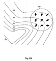
- Fig. 6A shows a human user interacting with a video object.
- FIG. 6A object 304 has been detected and is shown in outline form.
- One representation of the object within a computer's processing can use the outline definition depicted in Fig. 6A.
- Video screen 302 displays several image items, such as image 306 of a ball.
- Fig. 6B illustrates an influence image for the region of 308 of Fig. 6A.
- the outline image of the user's foot 320 and lower leg are used to generate successively larger outline areas.
- the original outline area 320's region is assigned a large pixel brightness value corresponding to white.
- Each successive outline area, 322, 324, 326, 328, 330 is assigned a progressively lower value so that a point farther away from the initial outline (white) area will have a lower pixel value.
- any number of outline areas can be used.
- the size and increments of outline areas can vary, as desired. For example, it is possible to use a continuous gradient, rather than discrete areas.
- the collection of all outline areas is referred to as the "influence image.”
- Fig. 6B ball item 306 impinges upon gradient areas 326, 328 and 330.
- direction lines are determined in the direction of the gradient of the pixel value field for the impinged areas.
- Fig. 6B shows three example direction lines within item 306.
- the direction lines can be combined, e.g., by averaging, or a select single line can be used.
- the processing also detects that the brightest outline area impinged by the item is outline area 326.
- Other approaches are possible.
- the brightness and gradient can be averaged over every point in the area of the image item, or on a subset of those points.
- some embodiments can include duration of contact as a factor in addition to the brightness and gradient.
- the interaction between an object, such as a person, and an item on the screen is computed using both the brightness of impinged outline areas and the direction as computed using one or more direction lines.
- the impinged brightness corresponds to the strength with which the user is "touching" the item.
- the gradient corresponds to the direction in (or from, depending on the sign of the calculation) which the item is being touched.
- the invention has been discussed with reference to specific embodiments thereof, these embodiments are illustrative, not restrictive, of the invention.
- the camera can be digital or analog.
- a stereo camera could be used in order to provide depth information as well as position.
- film and other types of media can be used and followed up by a digital conversion before inputting the data to a processor.
- Light sensors or detectors can be used.
- an array of photodetectors can be used in place of a camera.
- Other detectors not contemplated herein can be used with suitable results.
- any type of display device can be used with the present invention.
- video devices have been described in the various embodiments and configurations, other types of visual presentation devices can be used.
- a light-emitting diode (LED) array, organic LED (OLED), light-emitting pplymer (LEP), electromagnetic, cathode ray, plasma, mechanical or other display system can be employed.
- Virtual reality, three-dimensional or other types of displays can be employed.
- a user can wear imaging goggles or a hood so that they are immersed within a generated surrounding.
- the generated display can align with the user's perception of their surroundings to create an augmented, or enhanced, reality.
- One embodiment may allow a user to interact with an image of a character.
- the character can be computer generated, played by a human actor, etc.
- the character can react to the user's actions and body position. Interactions can include speech, co-manipulation of objects, etc.
- Multiple systems can be interconnected via, e.g., a digital network.
- a digital network For example, Ethernet, Universal Serial Bus (USB), IEEE 1394 (Firewire), etc., can be used.
- Wireless communication links such as defined by 802.11b, etc., can be employed.
- illumination as opposed to light
- radar signals, microwave or other electromagnetic waves can be used to advantage in situations where an object to detect (e.g., a metal object) is highly reflective of such waves. It is possible to adapt aspects of the system to other forms of detection such as by using acoustic waves in air or water.
- any other type of processing system can be used.
- a processing system that does not use a general-purpose computer can be employed.
- Processing systems using designs based upon custom or semi-custom circuitry or chips, application specific integrated circuits (ASICs), field-programmable gate arrays (FPGAs), multiprocessor, asynchronous or any type of architecture design or methodology can be suitable for use with the present invention.
Abstract
Description
- This application is a divisional application of EPA 02739710.8, which claims priority from U.S. Provisional Patent Application No. 60/296,189 filed June 5, 2001 entitled INTERACTIVE VIDEO DISPLAY SYSTEM THAT USES VIDEO INPUT.
- The present invention relates in general to image processing systems and more specifically to a system for receiving and processing an image of a human user to allow interaction with video displays.
- Image processing is used in many areas of analysis, education, commerce and entertainment. One aspect of image processing includes human-computer interaction by detecting human forms and movements to allow interaction with images. Applications of such processing can use efficient or entertaining ways of interacting with images to define digital shapes or other data, animate objects, create expressive forms, etc.
- Detecting the position and movement of a human body is referred to as "motion capture." With motion capture techniques, mathematical descriptions of a human performer's movements are input to a computer or other processing system. Natural body movements can be used as inputs to the computer to study athletic movement, capture data for later playback or simulation, enhance analysis for medical purposes, etc.
- Although motion capture provides benefits and advantages, motion capture techniques tend to be complex. Some techniques require the human actor to wear special suits with high-visibility points at several locations. Other approaches use radio-frequency or other types of emitters, multiple sensors and detectors, blue-screens, extensive post-processing, etc. Techniques that rely on simple visible-light image capture are usually not accurate enough to provide well-defined and precise motion capture.
- Some motion capture applications allow an actor, or user, to interact with images that are created and displayed by a computer system. For example, an actor may stand in front of a large video screen projection of several objects. The actor can move, or otherwise generate, modify, and manipulate, the objects by using body movements. Different effects based on an actor's movements can be computed by the processing system and displayed on the display screen. For example, the computer system can track a path of the actor in front of the display screen and render an approximation, or artistic interpretation, of the path onto the display screen. The images with which the actor interacts can be e.g., on the floor, wall or other surface; suspended three-dimensionally in space, displayed on one or more monitors, projection screens or other devices. Any type of display device or technology can be used to present images with which a user can control or interact.
- In some applications, such as point-of-sale, retail advertising, promotions, arcade entertainment sites, etc., it is desirable to capture the motion of an untrained user (e.g., a person passing by) in a very unobtrusive way. Ideally, the user will not need special preparation or training and the system will not use unduly expensive equipment. Also, the method and system used to motion capture the actor should, preferably, be invisible or undetectable to the user. Many real-world applications must work in environments where there are complex and changing background and foreground objects, short time intervals for the capture, changing lighting conditions and other factors that can make motion capture difficult.
- The present invention permits interaction between a user and a computer display system using the user's (or another object's) movement and position as input to a computer. The computer generates a display that responds to the user's position and movement. The generated display can include objects or shapes that can be moved, modified, or otherwise controlled by a user's body movements.
- An embodiment of the invention comprises a system having: a camera system operable to provide images of an object against a background; a display system operable to render video images onto a surface; and a processor coupled to receive said images from said camera system and coupled to drive said display system, said processor operable to adapt to changes in said background by analyzing changes over time in images from said camera system.
- According to an embodiment, said processor is operable to adapt to changes in said background by generating an adaptive model of said background by analyzing changes over time in images from said camera system.
- According to an embodiment, said processor is further operable to generate said video images based on said adaptive model and said images from said camera system.
- According to an embodiment, at least a portion of said surface coincides with said background.
- According to an embodiment, said processor is further operable to detect said object and positions thereof.
- According to an embodiment, said processor is further operable to determine an influence image, wherein the influence image includes a region around an object image derived from the object.
- According to an embodiment, said processor is further operable to determine an interaction between the object and at least one of the video images based on the influence image.
- According to an embodiment, said processor is further operable to determine a gradient of the influence image and to determine interaction between the object and at least one of the video images based on the gradient.
- According to an embodiment, said processor is further operable to determine a brightness of the influence image and to determine interaction between the object and the at least one video image based on the brightness.
- According to an embodiment, said processor is further operable to determine a brightness of the influence image and to determine interaction between the object and at least one of the video images based on the brightness.
- According to an embodiment, said processor is further operable to determine a gradient of the object and to determine interaction between the object and at least one of the video images based on the gradient.
- According to an embodiment, said processor is further operable to determine a brightness of an area derived from the object and to determine interaction between the object and at least one video image based on the brightness.
- According to an embodiment, said processor is further operable to determine an interaction between the object and at least one of the video images.
- According to an embodiment, said processor is further operable to determine a strength of said interaction.
- According to an embodiment, said processor is further operable to determine a direction of said interaction.
- According to an embodiment, said processor is further operable to determine a direction of said interaction.
- According to an embodiment, said interaction is one of: the object pushing the at least one video image; the object touching the at least one video image; the object deforming the at least one video image; and the object manipulating the at least one video image.
- According to an embodiment, said camera system comprises a light source that is strobed.
- According to an embodiment, said processor is further operable to process said images from said camera system based on said strobed light source.
- According to an embodiment, said processor is further operable to detect a lighting phenomenon due to sources of light other than said camera system light source, such as a lighting phenomenon causing shadows.
- According to an embodiment, said processor is further operable to generate said adaptive model of said background by identifying pixels in said frames having substantially constant brightness over time.
- According to an embodiment, said processor is further operable to generate said adaptive model of said background by computing median values over time for said pixels.
- According to an embodiment, said processor is further operable to generate said adaptive model of said background by incorporating into said adaptive model of said background changes in said background that occur over time.
- According to an embodiment, said processor is further operable to generate said adaptive model of said background by incorporating into said adaptive model of said background changes in said background that occur due to changes in lighting affecting said background.
- According to an embodiment, said processor is further operable to classify pixels of said images as either foreground or background by comparing said images to said adaptative model.
- According to an embodiment, said processor is further operable to generate said adaptive model of said background by incorporating into said adaptive model of said background information relating to at least a portion of said object that has remained substantially stationary for a period of time.
- According to an embodiment, said processor is further operable to generate said adaptive model of said background by computing a weighted average of a current image of said images from said camera system with said adaptive model of said background.
- According to an embodiment, said processor is further operable to tune said weighted average to change a rate at which said model of said background adapts to changes in said images from said camera system.
- According to an embodiment, said processor is further operable to generate said display item by distinguishing between foreground that corresponds to said object and said background.
- According to an embodiment, said distinguishing comprises comparing a current image of said images from said camera system with said adaptive model of said background.
- According to an embodiment, said distinguishing further comprises determining if differences between corresponding pixels in said current image of said images from said camera system and said adaptive model ofsaid background are greater than a threshold to determine location of said object.
- According to an embodiment, said camera system comprises two cameras to provide a stereo image, and wherein said processor is further operable to compute depth data based on said stereo image and to use said depth data to generate said model of said background.
- In an embodiment of the invention, displayed images are affected by a user's actions in real-time. The display can be projected around the user so that that the user's actions create effects that emanate from the user and affect display areas proximate to the user. Or the user can affect video objects such as by kicking, pushing, moving, deforming, touching, etc., items in video images. Interference between light used to display interactive images and light used to detect the user is minimized by using light of substantially different wavelengths.
- In one embodiment, a user is illuminated with infrared light that is not visible to the human eye. A camera that is sensitive to infrared light is used to capture an image of the user for position and motion analysis. Visible light is projected by a projector onto a screen, glass or other surface to display interactive images, objects, patterns or other shapes and effects. The display surface can be aligned around the user so that their physical presence within the display corresponds to their virtual presence, giving the experience of physically touching and interacting with virtual objects.
- One embodiment can use patterned illumination instead of a simple, non-visible, uniform "floodlight." With patterned illumination, a pattern, such as a checkerboard, random dot pattern, etc., is projected. The pattern is used by processes executing on a computer to interpret a camera image and to detect an object from a background and/or other items in a scene. The pattern can be generated as a background (so that it does not impinge upon an object to be detected) or the pattern can be projected over all of the camera's viewable scene so that it illuminates background, foreground and objects to be detected and motion captured.
- One way to achieve the patterned illumination includes using an infrared LED cluster or other non-visible light source in a slide projector. Another approach could use an infrared laser beam that is deflected, shuttered, scanned, etc.; to produce a pattern.
- Another way to achieve the patterned illumination is to use a regular "floodlight", but mark the aforementioned pattern onto the camera's viewable area using ink, dye, or paint that is either dark or highly reflective in the camera's receptive frequency. This ink, dye, or paint can be made invisible to the human eye so as to improve the aesthetics of the display.
- Another embodiment uses a gradient approach to determine object - image interaction. An "influence image" is created by creating a gradient aura, or gray scale transition, around a detected object. As the detected obj ect moves, the gradient aura is calculated in real time. As the gradient aura impinges upon a video image or item, the brightness and gradient in the region of the impinged item is calculated. The strength and direction of interaction (e.g., a pushing of the item) is a function of the brightness and gradient, respectively, of the impinged region.
- In one embodiment the invention provides a system for detecting an object and generating a display in response, the system comprising a first source, for outputting electromagnetic energy in a first wavelength range, a detector for detecting a reflection of the first source of electromagnetic energy from an object, a processor coupled to the detector for using the detected reflection to generate a display signal, a second source, for outputing electromagnetic energy at a second wavelength range, wherein the second source generates a visible display in response to the display signal, wherein the first and second wavelength ranges are different.
- In another embodiment the invention provides a method for detecting an object in an image captured with a camera, the method comprising using a patterned illumination to illuminate a background differently from the object; and using a processing system to define the object apart from the background.
- In another embodiment the invention provides a method for computing an interaction of an object with a video item, the method comprising using a processor to determine a gradient for the object; using a processor to determine a boundary for the video item; and identifying an interaction by using the gradient and the boundary.
- The invention also provides for an embodiment comprising a system for detecting an object and generating a display in response, the system comprising: a first source, for outputing electromagnetic energy in a first wavelength range; a detector for detecting a reflection of the first source of electromagnetic energy from an object; a processor coupled to the detector for using the detected reflection to generate a display signal; and a second source, for outputing electromagnetic energy at a second wavelength range, wherein the second source generates a visible display in response to the display signal, wherein the first and second wavelength ranges are different.
- According to an embodiment, the first source outputs light that is not in the visible spectrum and the second source outputs light that is in the visible spectrum.
- According to an embodiment, the first source outputs infrared light. According to an embodiment, the second source includes a video projector.
- According to an embodiment, the video projector projects images from above the object.
- According to an embodiment, the video projector projects images on a surface adjacent to the object.
- According to an embodiment, the surface is part of a rear-projection system.
- According to an embodiment, the surface is part of a front-projection system.
- According to an embodiment, the object includes a human user. According to an embodiment, the first source includes a pattern of illumination.
- According to an embodiment, the pattern includes a random dot pattern.
- An embodiment further comprises an infrared light-emitting diode cluster for generating the pattern of illumination.
- An embodiment further comprises a process for determining an influence image, wherein the influence image includes a region around an object image derived from the object.
- According to an embodiment, the visible display includes an item, the system further comprising a process for determining a gradient of the influence image; and a process for using the gradient to determine interaction between the object and the item.
- According to an embodiment, the visible display includes a rendering of a character.
- An embodiment comprises a method for obtaining an image of a human user wherein the human user is adjacent to a displayed image, the method comprising: using light at a first wavelength to illuminate the human user; using a camera responsive to the light at a first wavelength to detect the image of the human user; and using light at a second wavelength, different from the first wavelength, to generate the displayed image.
- According to an embodiment, multiple cameras are used.
- According to an embodiment, at least two cameras are used to produce a stereo effect.
- According to an embodiment, a plasma screen is used to generate the displayed image.
- According to an embodiment, the displayed image includes advertising.
- According to an embodiment, the displayed image is part of a video game.
- An embodiment further comprises strobing the light at a first wavelength.
- An embodiment further comprises interconnecting multiple systems so that information about image detection and displays can be transferred between the systems.
- An embodiment further comprises using the transferred information to create a single display from two or more displays.
- An embodiment comprises method for detecting an object in an image captured with a camera, the method comprising: using a patterned illumination to illuminate a background and not the object; and using a processing system to define the object apart from the background.
- According to an embodiment, the patterned illumination includes a random dot pattern.
- According to an embodiment, the patterned illumination includes a checkerboard pattern.
- According to an embodiment, the patterned illumination also illuminates the object.
- An embodiment comprises a method for detecting an object in an image captured with a camera, the method comprising: using a patterned background; and using a processing system to define the object apart from the background.
- An embodiment comprises a method for computing an interaction of an object with a video item, the method comprising: using a processor to determine a gradient for the object; using a processor to determine a boundary for the video item; and identifying an interaction by using the gradient and the boundary.
- An embodiment further comprises using a processor to determine a brightness of an area derived from the object; and identifying an interaction by using the brightness of the area and the boundary.
- According to an embodiment, the interaction is a person pushing the item.
- According to an embodiment, the interaction is a person touching the item.
- According to an embodiment, the interaction is a person deforming the item.
- According to an embodiment, the interaction is a person manipulating the item
- An embodiment comprises a system for detecting an object and generating an output in response, the system comprising: a first source, for outputing electromagnetic energy in a first wavelength range; a detector for detecting a reflection of the first source of electromagnetic energy from an object; a processor coupled to the detector for using the detected reflection to generate a display signal; a second source, for outputing electromagnetic energy at a second wavelength range, wherein the second source generates a visible display in response to the display signal, wherein the first and second wavelength ranges are different; and audio output for outputing audio.
- Fig. 1 shows a first configuration of an embodiment using a co-located projector and camera;
- Fig. 2 shows an overhead projection configuration;
- Fig. 3 shows a rear-projection configuration;
- Fig. 4 shows a side-projection configuration;
- Fig. 5A illustrates a subject under uniform illumination;
- Fig. 5B illustrates a background under random dot pattern illumination;
- Fig. 5C illustrates a subject and background under random dot pattern illumination;
- Fig. 5D shows a result of detecting a subject from a background using random dot pattern illumination;
- Fig. 6A shows a human user interacting with a video object; and
- Fig. 6B illustrates an influence image.
- Several configurations of the invention are described below. In an embodiment the present invention uses a first light source to illuminate a user, or another object. The first light source uses light that is not visible to humans. For example, infrared or ultraviolet light can be used. A camera that is sensitive to light at the wavelength range of the first light source is used to detect a user who is illuminated by the first light source. A computer (or other processing system) is used to process the detected object image and to generate images for display. A second light source (e.g., a projector, video screen, etc.) is used to display the generated display images to a human user or viewers. The displayed images are at wavelengths that minimize interference with the camera's object detection. Typically, the visible spectrum is used to display the images.
- In an embodiment, the display surrounds the user such that the user's virtual presence is aligned with the user's physical presence. Thus, the virtual scene on the display has a physical location around the user, and the user's movement within the display will cause identical movement of the user's representation within the virtual scene. For example, the user can impinge on a virtual object's physical location and know that this will cause their virtual representation to touch the virtual object in the computer system. The use of the term "touch" or "touching" in this specification does not mean physical contact with an obj ect, such as a person, and an image item. Rather the notion of touching means that the object's position and action in physical space is translated into an effect in a generated image, including effects of moving items in the generated images.
- Displayed images or items can include objects, patterns, shapes or any visual pattern, effect, etc. Aspects of the invention can be used for applications such as interactive lighting effects for people at clubs or events, interactive advertising displays, characters and virtual objects that react to the movements of passers-by, interactive ambient lighting for public spaces such as restaurants, shopping malls, sports venues, retail stores, lobbies and parks, video game systems, and interactive informational displays. Other applications are possible and are within the scope of the invention.
- Fig. 1 shows a front-projection embodiment of the invention using a co-located camera and projector. In Fig. 1, a person 1 is illuminated by an infrared (or other non-visible light)
lamp 2. The image of the person is photographed by an infrared (or other non-visible light)camera 3. This signal is transmitted real-time 4 tocomputer 5. The computer performs the object detection algorithm, and generates the video effect in real time. The effect is transmitted 6 real-time to video projector 7. The projector projects the resulting image onto ascreen 8 or some other surface. The video effect is then displayed 9 on the screen, in real time, and aligned with the person. - Fig. 2 shows an overhead projection configuration of the system.
Component 10 includes the aforementioned system.Component 10 is shown mounted vertically here, but the camera, projector, and light source within 10 can also be mounted horizontally and then redirected downwards with a mirror. A person moving on theground 11 can have the video signal projected onto the ground around them 12. The person's own shadow obscures a minimal amount of the image when the projector is directly overhead. - Figs. 3 and 4 show two more alternate configurations for the camera and projector. In both figures,
camera 20 captures objects such as aperson 22 in front of ascreen 23. The angle viewed by the camera is shown at 21. In Fig. 3projector 25 is placed behind the screen. The cast light fromprojector 24 can be seen on the screen from both sides. In Fig. 4,projector 25 is at an oblique angle to the screen; itslight cone 24 is shown. Both of these configurations make it more likely that there are no shadows obstructing the projected image. - As described in the configurations, above, a video camera is used to capture the scene at a particular location for input into the computer. In most configurations of the device, the camera views part of the output video display. To prevent unwanted video feedback, the camera can operate at a wavelength that is not used by the video display. In most cases, the display will use the visible light spectrum. In this case, the camera must photograph in a non-visible wavelength, such as infrared, so that the video display output is not detected.
- The scene being videotaped must be illuminated in light of the camera's wavelength. In the case of infrared, sources including sunlight, a heat lamp or infrared LEDs can be used to illuminate the scene. These lights can be positioned anywhere; however, the camera's view of spurious shadows from these lights can be minimized by placing the light source in proximity to the camera. A light source, such as one or more lights, can illuminate objects with a uniform lighting, as opposed to the patterned illumination discussed, below. In a preferred embodiment, the video signal is exported in real-time to the computer. However, other embodiments need not achieve real-time or near-real-time and can process object or video images (i.e., display images) at times considerably prior to displaying the images.
- This component is designed to be modular; any computer software that utilizes the video input from the previous component and outputs the results to a video display can be used here.
- Most instances of this component will have two parts: the first part handles the detection of mobile objects from static background, while the second part utilizes the object information to generate a video output. Numerous instances of each part will be described here; these instances are simply meant to be examples, and are by no means exhaustive.
- In the first part, the live image from the video camera is processed real-time in order to separate mobile objects (e.g. people) from the static background, regardless of what the background is. The processing can be done as follows:
- First, input frames from the video camera are converted to grayscale to reduce the amount of data and to simplify the detection process. Next, they may be blurred slightly to reduce noise.
- Any object that does not move over a long period of time is presumed to be background; therefore, the system is able to eventually adapt to changing lighting or background conditions. A model image of the background can be generated by numerous methods, each of which examines the input frames over a range of time. In one method, the last several input frames (or a subset thereof) are examined to generate a model of the background, either through averaging, generating the median, detecting periods of constant brightness, or other heuristics. The length of time over which the input frames are examined determines the rate at which the model of the background adapts to changes in the input image.
- In another method, the background model is generated at each time step (or more infrequently) by computing a weighted average: of the current frame and the background model from the previous time step. The weight of the current frame is relatively small in this calculation; thus, changes in the real background are gradually assimilated into the background model. This weight can be tuned to change the rate at which the background model adapts to changes in the input image.
- An object of interest is presumed to differ in brightness from the background. In order to find objects at each time step, the current video input is subtracted from the model image of the background. If the absolute value of this difference at a particular location is larger than a particular threshold, then that location is classified as an object; otherwise, it is classified as background.
- The second part can be any program that takes the object/background classification of an image (possibly in addition to other data) as input, and outputs a video image based on this input, possibly in real time. This program can take on an infinite number of forms, and is thus as broadly defined as a computer application. For example, this component could be as simple as producing a spotlight in the shape of the detected objects, or as complicated as a paint program controlled through gestures made by people who are detected as objects. In addition, applications could use other forms of input, such as sound, temperature, keyboard input etc. as well as additional forms of.output, such as audio, tactile, virtual reality, aromatic, etc.
- One major class of applications includes special effects that use the object/background classification as input. For example, stars, lines, or other shapes could be drawn in the output video image in a random portion of the locations that were classified as "object". These shapes could then be set to gradually fade away over time, so that people leave transient trails of shapes behind them as they move around. The following are examples of other effects in the same class:
- - contours and ripples surrounding the objects
- - a grid which is deformed by the presence of objects
- - simulations of flame and wind, and other matrix convolutions applied to objects
- - special effects that pulse to the beat of the music, which is detected separately
- Another major class of applications allows the real objects to interact with virtual objects and characters. For example, an image showing a group of ducklings could be programmed to follow behind any real object (e.g. a person) that walks in front of the display.
- In addition, computer games that can be played by people moving in front of the camera form another class of applications.
- However, this list is not exclusive; this component is designed to be programmable, and thus can run any application.
- The output of the processing software from the previous component is displayed visually. Possible displays include, but are not limited to video projectors, televisions, plasma displays, and laser shows. The displayed image can be aligned with the video camera's input range so that the video effects align with the locations of the people causing them. Since some configurations of the video camera can detect objects in non-visible light, the problem of the display interfering with the camera is avoided.
- There are numerous possible configurations for the different components. For example, the camera and a video projector can be in the same location and pointed in the same direction The camera and projector can then be pointed at a wall as shown in Fig. 1, pointed at the ground, redirected with a mirror as shown in Fig. 2, or pointed at any other surface. Alternatively, the projector could be placed behind the screen as shown in Fig. 3 so that the display is identical to the one in Fig. 1, but the person is no longer in the way of the projection, so they do not cast a shadow. The shadow could also be avoided by placing the projector at an oblique angle to the screen as shown in Fig. 4. The video display could also be a large-screen TV, plasma display, or video wall. While the aforementioned configurations all have the video display lined up with the video input, this is not necessary; the video display could be placed anywhere. The preceding list is not exhaustive; there are numerous additional possible configurations.
- The overall system can be networked, allowing vision information and processing software state information to be exchanged between systems. Thus an object detected in the vision signal of one system can affect the processing software in another system. In addition, a virtual item in the display of one system could move to other systems. If the displays of multiple systems are aligned together so that they form a single larger display, then the multiple systems can be made to function as if they were a single very large system, with objects and interactions moving seamlessly across display boundaries.
- One common problem with the vision system is that, in cases where there is uncontrollable ambient illumination (e.g. sunlight) of the camera's viewable area from a significantly different angle than the camera, objects cast shadows onto the background. If these shadows are strong enough, the vision system may mistake them for objects. These shadows can be detected and removed by strobing the camera's light source. By subtracting a camera input image with ambient light alone from a camera input image with both the ambient light and the camera's light, the system yields an image that captures the scene as if only the camera's light were being used, thus eliminating the detectable shadows from the ambient light.
- Additional accuracy in detecting objects with the images captured by the camera can be obtained by using patterned illumination or patterned markings.
- One shortcoming of using a simple floodlight illumination system for computer vision is that if the colors of objects being viewed by the camera are very similar, then the objects can be very difficult to detect. If the camera operates in monochrome it is much more likely for the object and background to look the same.
- Using a patterned object to cover camera's viewable area can improve object detection. If a pattern that contains two or more colors intermingled in close proximity is used, it is highly unlikely that other objects will have a similar look since at least one color of the pattern will look different from the color of surrounding objects. If a patterned object, such as a screen, is used as a background before which are the objects to be detected, then objects that pass in front of the patterned screen are more easily detected by the vision algorithm.
- For example, in an infrared vision application the patterned object could be a background mat that appears white to the human eye, but contains a light & dark checkered pattern that is invisible to the human eye but visible to the camera. By using a pattern that is not in the visible light spectrum, the patterned mat will not interfere with the aesthetics of the system. The display system (e.g., projection video) can project output images onto the mat, as described above. A process executing on a processing system such as a computer system can be provided with the background pattern, thus making detection of an obj ect in front of the mat easier, although the system could learn the patterned background in the same way that the vision algorithm learns any other background. Also, the ability of the system to adapt to changes in background light brightness would not be adversely affected.
- A patterned illumination can also be projected from a light source onto the camera's viewable area. As long as the camera and invisible light source are in different, offset locations, parallax effects will cause the camera's view of the projected pattern to be distorted as objects move through the camera's viewing area. This distortion helps make objects that have similar colors stand out from each other. If the difference between the two images seen by the camera is taken, the result will show the shape of any object that has appeared, disappeared, or moved between the two images. If the image of an object in front of the background is subtracted from an image of the background alone, the result is an image that is zero where there is background and nonzero where there are other objects. This technique can be used in combination with other aspects of the invention discussed, herein.
- A patterned light source can be achieved through several means. One method is to use an infrared light-emitting diode (LED) cluster or another non-visible light source in a slide projector. A set of lenses would be used to focus the light source through a slide containing the desired pattern, thus casting the pattern's image onto the camera's viewing area. In another method, an infrared laser beam could be shined onto a laser pattern generator or other scattering device in order to produce a light pattern on the camera's viewing area. Light can be deflected, shuttered, scanned, etc., in order to achieve a pattern. Many other approaches are possible.
- A patterned light source is also useful for 3-D computer vision. 3-D computer vision techniques such as the Marr-Poggio algorithm take as input two images of the same scene taken from slightly different angles. The patterns on the images are matched up to determine the amount of displacement, and hence the distance from the camera, at each point in the image. The performance of this algorithm degrades when dealing with objects of uniform color because uniform color makes it difficult to match up the corresponding sections in the image pair. Thus, the patterned light source can improve the distance estimates of some 3D computer vision algorithms.
- The two input images to these 3-D vision algorithms are usually generated using a pair of cameras pointed at the scene. However, it would also be possible to use only one camera. The second image could be an entirely undistorted version of the projected pattern, which is known ahead of time. This image of the pattern is essentially identical to what a second camera would see if it were placed at the exact same location as the patterned light source. Thus, the single camera's view and the projected pattern together could be used as an input to the 3-D vision algorithm. Alternatively, the second image could be an image of the background alone, taken from the same camera.
- While many different kinds of patterns can be used, a high-resolution random dot pattern has certain advantages for both 2-D and 3-D vision. Due to the randomness of the dot pattern, each significantly sized section of the dot pattern is highly unlikely to look like any other section of the pattern. Thus, the displaced pattern caused by the presence of an object in the viewing area is highly unlikely to look similar to the pattern without the object there. This maximizes the ability of the vision algorithm to detect displacements in the pattern, and therefore objects. Using a regular pattern such as a grid can cause some difficulty because different sections of the pattern are identical, causing the displaced pattern to often look like the non-displaced pattern.
- Figs. 5A-D show the usefulness of a random dot pattern in detecting an object. Fig. 5A shows a picture of a person under normal illumination. The person has a similar brightness to the background, making detection difficult. In Fig. 5B, a random dot pattern is projected onto the background from a light source near the camera. When the person stands in front of this pattern, the pattern reflected off of the person is displaced, as shown in Fig. 5C. By taking the difference between the images in Figs. 5B and 5C, the image of Fig. 5D is obtained which defines the image area of the person with a strong signal.
- Other approaches can be used to improve object detection. For example, a light source can be "strobed" or turned on-and-off periodically so that detection of shadows due to other light sources (e.g., ambient light) is made easier.
- Once an object has been detected and defined the preferred embodiment uses a gradient aura to determine degree and direction of interaction of the object with a displayed image item.
- Fig. 6A shows a human user interacting with a video object.
- In Fig. 6A, object 304 has been detected and is shown in outline form. One representation of the object within a computer's processing can use the outline definition depicted in Fig. 6A.
Video screen 302 displays several image items, such asimage 306 of a ball. - Fig. 6B illustrates an influence image for the region of 308 of Fig. 6A.
- In Fig. 6B, the outline image of the user's
foot 320 and lower leg are used to generate successively larger outline areas. Theoriginal outline area 320's region is assigned a large pixel brightness value corresponding to white. Each successive outline area, 322, 324, 326, 328, 330 is assigned a progressively lower value so that a point farther away from the initial outline (white) area will have a lower pixel value. Note that any number of outline areas can be used. Also, the size and increments of outline areas can vary, as desired. For example, it is possible to use a continuous gradient, rather than discrete areas. The collection of all outline areas is referred to as the "influence image." - The influence image is compared to different image items. In Fig. 6B,
ball item 306 impinges upongradient areas item 306. The direction lines can be combined, e.g., by averaging, or a select single line can be used. The processing also detects that the brightest outline area impinged by the item isoutline area 326. Other approaches are possible. For example, the brightness and gradient can be averaged over every point in the area of the image item, or on a subset of those points. Also, some embodiments can include duration of contact as a factor in addition to the brightness and gradient. - The interaction between an object, such as a person, and an item on the screen is computed using both the brightness of impinged outline areas and the direction as computed using one or more direction lines. The impinged brightness corresponds to the strength with which the user is "touching" the item. The gradient corresponds to the direction in (or from, depending on the sign of the calculation) which the item is being touched.
- Although the invention has been discussed with reference to specific embodiments thereof, these embodiments are illustrative, not restrictive, of the invention. For example, although the described embodiments use a camera as a detector, different types of detection devices can be employed. The camera can be digital or analog. A stereo camera could be used in order to provide depth information as well as position. In cases where processing and display are not done in real time, film and other types of media can be used and followed up by a digital conversion before inputting the data to a processor. Light sensors or detectors can be used. For example, an array of photodetectors can be used in place of a camera. Other detectors not contemplated herein can be used with suitable results.
- In general, any type of display device can be used with the present invention. For example, although video devices have been described in the various embodiments and configurations, other types of visual presentation devices can be used. A light-emitting diode (LED) array, organic LED (OLED), light-emitting pplymer (LEP), electromagnetic, cathode ray, plasma, mechanical or other display system can be employed.
- Virtual reality, three-dimensional or other types of displays can be employed. For example, a user can wear imaging goggles or a hood so that they are immersed within a generated surrounding. In this approach, the generated display can align with the user's perception of their surroundings to create an augmented, or enhanced, reality. One embodiment may allow a user to interact with an image of a character. The character can be computer generated, played by a human actor, etc. The character can react to the user's actions and body position. Interactions can include speech, co-manipulation of objects, etc.
- Multiple systems can be interconnected via, e.g., a digital network. For example, Ethernet, Universal Serial Bus (USB), IEEE 1394 (Firewire), etc., can be used. Wireless communication links such as defined by 802.11b, etc., can be employed. By using multiple systems, users in different geographic locations can cooperate, compete, or otherwise interact with each other through generated images. Images generated by two or more systems can be "tiled" together, or otherwise combined to produce conglomerate displays.
- Other types of illumination, as opposed to light, can be used. For example, radar signals, microwave or other electromagnetic waves can be used to advantage in situations where an object to detect (e.g., a metal object) is highly reflective of such waves. It is possible to adapt aspects of the system to other forms of detection such as by using acoustic waves in air or water.
- Although computer systems have been described to receive and process the object image signals and to generate display signals, any other type of processing system can be used. For example, a processing system that does not use a general-purpose computer can be employed. Processing systems using designs based upon custom or semi-custom circuitry or chips, application specific integrated circuits (ASICs), field-programmable gate arrays (FPGAs), multiprocessor, asynchronous or any type of architecture design or methodology can be suitable for use with the present invention.
-
- 1. A system for detecting an object and generating a display in response, the system comprising
- a first source, for outputing electromagnetic energy in a first wavelength range;
- a detector for detecting a reflection of the first source of electromagnetic energy from an obj ect;
- a processor coupled to the detector for using the detected reflection to generate a display signal;
- a second source, for outputing electromagnetic energy at a second wavelength range, wherein the second source generates a visible display in response to the display signal, wherein the first and second wavelength ranges are different.
- 2. The system of feature 1, wherein the first source outputs light that is not in the visible spectrum and wherein the second source outputs light that is in the visible spectrum.
- 3. The system of
feature 2, wherein the first source outputs infrared light. - 4. The system of feature 1, wherein the second source includes a video projector.
- 5. The system of
feature 4, wherein the video projector projects images from above the object. - 6. The system of
feature 4, wherein the video projector projects images on a surface adj acent to the obj ect. - 7. The system of feature 6, wherein the surface is part of a rear-projection system.
- 8. The system of feature 6, wherein the surface is part of a front-projection system.
- 9. The system of feature 1, wherein the object includes a human user.
- 10. The system of feature 1, wherein the first source includes a pattern of illumination.
- 11. The system of
feature 10, wherein the pattern includes a random dot pattern. - 12. The system of
feature 10, further comprising
an infrared light-emitting diode cluster for generating the pattern of illumination. - 13. The system of feature 1, further comprising
a process for determining an influence image, wherein the influence image includes a region around an object image derived from the object. - 14. The system of feature 13, wherein the visible display includes an item, the system further comprising
a process for determining a gradient of the influence image; and
a process for using the gradient to determine interaction between the object and the item. - 15. The system of feature 1, wherein the visible display includes a rendering of a character.
- 16. A method for obtaining an image of a human user wherein the human user is adjacent to a displayed image, the method comprising
using light at a first wavelength to illuminate the human user;
using a camera responsive to the light at a first wavelength to detect the image of the human user; and
using light at a second wavelength, different from the first wavelength, to generate the displayed image. - 17. The method of featurel6, wherein multiple cameras are used.
- 18. The method of feature 17, wherein at least two cameras are used to produce a stereo effect.
- 19. The method of feature 16, wherein a plasma screen is used to generate the displayed image.
- 20. The method of feature 16, wherein the displayed image includes advertising.
- 21. The method of feature 16, wherein the displayed image is part of a video game.
- 22.The method of feature 16, further comprising
strobing the light at a first wavelength. - 23. The method of feature 16, further comprising
interconnecting multiple systems so that information about image detection and displays can be transferred between the systems. - 24.The method of
feature 23, further comprising
using the transferred information to create a single display from two or more displays. - 25. A method for detecting an object in an image captured with a camera, the method comprising
using a patterned illumination to illuminate a background and not the object; and
using a processing system to define the object apart from the background. - 26. The system of
feature 25, wherein the patterned illumination includes a random dot pattern. - 27. The system of
feature 25, wherein the patterned illumination includes a checkerboard pattern. - 28. The system of
feature 25, wherein the patterned illumination also illuminates the object. - 29. A method for detecting an object in an image captured with a camera, the method comprising
using a patterned background; and
using a processing system to define the obj ect apart from the background. - 30. A method for computing an interaction of an object with a video item, the method comprising
using a processor to determine a gradient for the object;
using a processor to determine a boundary for the video item; and
identifying an interaction by using the gradient and the boundary. - 31. The system of feature 30, further comprising
using a processor to determine a brightness of an area derived from the object; and
identifying an interaction by using the brightness of the area and the boundary. - 32. The system of feature 30, wherein the interaction is a person pushing the item.
- 33. The system of feature 30, wherein the interaction is a person touching the item.
- 34. The system of feature 30, wherein the interaction is a person deforming the item.
- 35. The system of feature 30, wherein the interaction is a person manipulating the item
- 36. A system for detecting an object and generating an output in response, the system comprising
a first source, for outputing electromagnetic energy in a first wavelength range;
a detector for detecting a reflection of the first source of electromagnetic energy from an object;
a processor coupled to the detector for using the detected reflection to generate a display signal;
a second source, for outputing electromagnetic energy at a second wavelength range, wherein the second source generates a visible display in response to the display signal, wherein the first and second wavelength ranges are different; and
audio output for outputing audio. - [80] Thus, the scope of the invention is to be determined solely by the appended claims.
Claims (32)
- A system comprising:a camera system operable to provide images of an object against a background;a display system operable to render video images onto a surface; anda processor coupled to receive said images from said camera system and coupled to drive said display system, said processor operable to adapt to changes in said background by analyzing changes over time in images from said camera system.
- A system in accordance with claim 1, wherein said processor is operable to adapt to changes in said background by generating an adaptive model of said background by analyzing changes over time in images from said camera system.
- A system in accordance with Claim 2, wherein said processor is further operable to generate said video images based on said adaptive model and said images from said camera system.
- A system in accordance with Claim 1, wherein at least a portion of said surface coincides with said background.
- A system in accordance with Claim 1, wherein said processor is further operable to detect said object and positions thereof.
- A system in accordance with Claim 1, wherein said processor is further operable to determine an influence image, wherein the influence image includes a region around an object image derived from the object.
- A system in accordance with Claim 6, wherein said processor is further operable to determine an interaction between the object and at least one of the video images based on the influence image.
- A system in accordance with Claim 6, wherein said processor is further operable to determine a gradient of the influence image and to determine interaction between the object and at least one of the video images based on the gradient.
- A system in accordance with Claim 8, wherein said processor is further operable to determine a brightness of the influence image and to determine interaction between the object and the at least one video image based on the brightness.
- A system in accordance with Claim 6, wherein said processor is further operable to determine a brightness of the influence image and to determine interaction between the object and at least one of the video images based on the brightness.
- A system in accordance with Claim 1, wherein said processor is further operable to determine a gradient of the object and to determine interaction between the object and at least one of the video images based on the gradient. interaction between the object and at least one of the video images based on the gradient.
- A system in accordance with Claim 1 or 11, wherein said processor is further operable to determine a brightness of an area derived from the object and to determine interaction between the object and at least one video image based on the brightness.
- A system in accordance with Claim 1, wherein said processor is further operable to determine an interaction between the object and at least one of the video images.
- A system in accordance with Claim 13, wherein said processor is further operable to determine a strength of said interaction.
- A system in accordance with Claim 14, wherein said processor is further operable to determine a direction of said interaction.
- A system in accordance with Claim 13, wherein said processor is further operable to determine a direction of said interaction.
- A system in accordance with Claim 13, wherein said interaction is one of:the object pushing the at least one video image;the object touching the at least one video image;the object deforming the at least one video image; andthe object manipulating the at least one video image.
- A system in accordance with Claim 1, wherein said camera system comprises a light source that is strobed.
- A system in accordance with Claim 18, wherein said processor is further operable to process said images from said camera system based on said strobed light source.
- A system in accordance with Claim 19, wherein said processor is further operable to detect a lighting phenomenon due to sources of light other than said camera system light source, such as a lighting phenomenon causing shadows.
- The system as described in Claim 2 wherein said processor is further operable to generate said adaptive model of said background by identifying pixels in said frames having substantially constant brightness over time.
- The system as described in Claim 2 or 21, wherein said processor is further operable to generate said adaptive model of said background by computing median values over time for said pixels.
- The system as described in Claim 2, wherein said processor is further operable to generate said adaptive model of said background by
- The system as described in Claim 2, wherein said processor is further operable to generate said adaptive model of said background by incorporating into said adaptive model of said background changes in said background that occur due to changes in lighting affecting said background.
- The system as described in Claim 2, wherein said processor is further operable to classify pixels of said images as either foreground or background by comparing said images to said adaptative model.
- The system as described in Claim 2, wherein said processor is further operable to generate said adaptive model of said background by incorporating into said adaptive model of said background information relating to at least a portion of said object that has remained substantially stationary for a period of time.
- The system as described in Claim 2, wherein said processor is further operable to generate said adaptive model of said background by computing a weighted average of a current image of said images from said camera system with said adaptive model of said background.
- The system as described in Claim 27, wherein said processor is further operable to tune said weighted average to change a rate at which said model of said background adapts to changes in said images from said camera system.
- The system as described in Claim 2, wherein said processor is further operable to generate said display item by distinguishing between foreground that corresponds to said object and said background.
- The system as described in Claim 29 wherein said distinguishing comprises comparing a current image of said images from said camera system with said adaptive model of said background.
- The system as described in Claim 30, wherein said distinguishing further comprises determining if differences between corresponding pixels in said current image of said images from said camera system and said adaptive model of said background are greater than a threshold to determine location of said object.
- The system as described in Claim 1 wherein said camera system comprises two cameras to provide a stereo image, and wherein said processor is further operable to compute depth data based on said stereo image and to use said depth data to generate said model of said background.
Applications Claiming Priority (3)
| Application Number | Priority Date | Filing Date | Title |
|---|---|---|---|
| US29618901P | 2001-06-05 | 2001-06-05 | |
| US10/160,217 US7259747B2 (en) | 2001-06-05 | 2002-05-28 | Interactive video display system |
| EP02739710A EP1393549B1 (en) | 2001-06-05 | 2002-06-04 | Interactive video display system |
Related Parent Applications (1)
| Application Number | Title | Priority Date | Filing Date |
|---|---|---|---|
| EP02739710A Division EP1393549B1 (en) | 2001-06-05 | 2002-06-04 | Interactive video display system |
Publications (2)
| Publication Number | Publication Date |
|---|---|
| EP1689172A1 true EP1689172A1 (en) | 2006-08-09 |
| EP1689172B1 EP1689172B1 (en) | 2016-03-09 |
Family
ID=36642691
Family Applications (1)
| Application Number | Title | Priority Date | Filing Date |
|---|---|---|---|
| EP06010825.5A Expired - Lifetime EP1689172B1 (en) | 2001-06-05 | 2002-06-04 | Interactive video display system |
Country Status (1)
| Country | Link |
|---|---|
| EP (1) | EP1689172B1 (en) |
Cited By (29)
| Publication number | Priority date | Publication date | Assignee | Title |
|---|---|---|---|---|
| WO2010035046A1 (en) * | 2008-09-26 | 2010-04-01 | Cybula Ltd | Image recognition |
| US7710391B2 (en) | 2002-05-28 | 2010-05-04 | Matthew Bell | Processing an image utilizing a spatially varying pattern |
| US7809167B2 (en) | 2003-10-24 | 2010-10-05 | Matthew Bell | Method and system for processing captured image information in an interactive video display system |
| US7834846B1 (en) | 2001-06-05 | 2010-11-16 | Matthew Bell | Interactive video display system |
| US8035624B2 (en) | 2002-05-28 | 2011-10-11 | Intellectual Ventures Holding 67 Llc | Computer vision based touch screen |
| US8081822B1 (en) | 2005-05-31 | 2011-12-20 | Intellectual Ventures Holding 67 Llc | System and method for sensing a feature of an object in an interactive video display |
| US8098277B1 (en) | 2005-12-02 | 2012-01-17 | Intellectual Ventures Holding 67 Llc | Systems and methods for communication between a reactive video system and a mobile communication device |
| DE102009025236B4 (en) * | 2008-06-20 | 2012-02-16 | Northrop Grumman Corp. | Interface system for gesture recognition with a light-scattering screen |
| US8139110B2 (en) | 2007-11-01 | 2012-03-20 | Northrop Grumman Systems Corporation | Calibration of a gesture recognition interface system |
| US8159682B2 (en) | 2007-11-12 | 2012-04-17 | Intellectual Ventures Holding 67 Llc | Lens system |
| US8180114B2 (en) | 2006-07-13 | 2012-05-15 | Northrop Grumman Systems Corporation | Gesture recognition interface system with vertical display |
| US8199108B2 (en) | 2002-12-13 | 2012-06-12 | Intellectual Ventures Holding 67 Llc | Interactive directed light/sound system |
| US8230367B2 (en) | 2007-09-14 | 2012-07-24 | Intellectual Ventures Holding 67 Llc | Gesture-based user interactions with status indicators for acceptable inputs in volumetric zones |
| US8234578B2 (en) | 2006-07-25 | 2012-07-31 | Northrop Grumman Systems Corporatiom | Networked gesture collaboration system |
| US8259163B2 (en) | 2008-03-07 | 2012-09-04 | Intellectual Ventures Holding 67 Llc | Display with built in 3D sensing |
| US8300042B2 (en) | 2001-06-05 | 2012-10-30 | Microsoft Corporation | Interactive video display system using strobed light |
| EP2571257A1 (en) * | 2011-09-14 | 2013-03-20 | Ricoh Company, Ltd. | Projector device and operation detecting method |
| US8432448B2 (en) | 2006-08-10 | 2013-04-30 | Northrop Grumman Systems Corporation | Stereo camera intrusion detection system |
| US8487866B2 (en) | 2003-10-24 | 2013-07-16 | Intellectual Ventures Holding 67 Llc | Method and system for managing an interactive video display system |
| US8589824B2 (en) | 2006-07-13 | 2013-11-19 | Northrop Grumman Systems Corporation | Gesture recognition interface system |
| US8595218B2 (en) | 2008-06-12 | 2013-11-26 | Intellectual Ventures Holding 67 Llc | Interactive display management systems and methods |
| US8972902B2 (en) | 2008-08-22 | 2015-03-03 | Northrop Grumman Systems Corporation | Compound gesture recognition |
| US9128519B1 (en) | 2005-04-15 | 2015-09-08 | Intellectual Ventures Holding 67 Llc | Method and system for state-based control of objects |
| WO2016077913A1 (en) * | 2014-11-17 | 2016-05-26 | Triotech Amusement Inc. | Gaming method and system for projecting volumetric images onto a physical scene |
| EP3029633A1 (en) * | 2014-12-02 | 2016-06-08 | Honeywell International Inc. | System and method of foreground extraction for digital cameras |
| US9377874B2 (en) | 2007-11-02 | 2016-06-28 | Northrop Grumman Systems Corporation | Gesture recognition light and video image projector |
| US9696808B2 (en) | 2006-07-13 | 2017-07-04 | Northrop Grumman Systems Corporation | Hand-gesture recognition method |
| GB2583848A (en) * | 2014-05-21 | 2020-11-11 | Tangible Play Inc | Virtualization of tangible interface objects |
| CN112911182A (en) * | 2018-06-28 | 2021-06-04 | 腾讯科技(深圳)有限公司 | Game interaction method, device, terminal and storage medium |
Citations (3)
| Publication number | Priority date | Publication date | Assignee | Title |
|---|---|---|---|---|
| US5528263A (en) * | 1994-06-15 | 1996-06-18 | Daniel M. Platzker | Interactive projected video image display system |
| WO1998038533A1 (en) * | 1997-02-28 | 1998-09-03 | Siemens Aktiengesellschaft | Method and device for detecting an object in an area radiated by waves in the invisible spectral range |
| US6176782B1 (en) * | 1997-12-22 | 2001-01-23 | Philips Electronics North America Corp. | Motion-based command generation technology |
-
2002
- 2002-06-04 EP EP06010825.5A patent/EP1689172B1/en not_active Expired - Lifetime
Patent Citations (4)
| Publication number | Priority date | Publication date | Assignee | Title |
|---|---|---|---|---|
| US5528263A (en) * | 1994-06-15 | 1996-06-18 | Daniel M. Platzker | Interactive projected video image display system |
| WO1998038533A1 (en) * | 1997-02-28 | 1998-09-03 | Siemens Aktiengesellschaft | Method and device for detecting an object in an area radiated by waves in the invisible spectral range |
| US6353428B1 (en) | 1997-02-28 | 2002-03-05 | Siemens Aktiengesellschaft | Method and device for detecting an object in an area radiated by waves in the invisible spectral range |
| US6176782B1 (en) * | 1997-12-22 | 2001-01-23 | Philips Electronics North America Corp. | Motion-based command generation technology |
Non-Patent Citations (9)
| Title |
|---|
| "SUPREME PARTICLES: R111", <URL:HTTP://WWW.R111.ORG>, 1999, XP002989704 * |
| ARTCOM, PROJEKT BODYMOVER |
| ARTCOM: "PROJEKT BODYMOVER 2000; Koerperbewegung als Mittel zur Schaffung eines audio-visuellen Raum-Erlebnisses", <URL:HTTP://WWW.ARTCOM.DE/IMAGES/STORIES/2_PRO_BODYMOVER/BODYMOVER_D.PDF>, 2000, XP002989289 * |
| FLAVIA, SOME) COMPUTER VISION BASED INTERFACES FOR INTERACTIVE ART AND ENTERTAINMENT INSTALLATIONS |
| FOERTERER, FLUIDUM 1 |
| HELIKOPTER |
| HUANG ET AL., SHADOW VISION |
| LEIBE, THE PERCEPTIVE WORKBENCH: TOWARD SPONTANEOUS AND NATURAL INTERACTION IN SEMI-IMMERSIVE VIRTUAL ENVIRONMENTS |
| PARADISO ET AL., OPTICAL TRACKING FOR MUSIC AND DANCE PERFORMANCE |
Cited By (45)
| Publication number | Priority date | Publication date | Assignee | Title |
|---|---|---|---|---|
| US7834846B1 (en) | 2001-06-05 | 2010-11-16 | Matthew Bell | Interactive video display system |
| US8300042B2 (en) | 2001-06-05 | 2012-10-30 | Microsoft Corporation | Interactive video display system using strobed light |
| US7710391B2 (en) | 2002-05-28 | 2010-05-04 | Matthew Bell | Processing an image utilizing a spatially varying pattern |
| US8035624B2 (en) | 2002-05-28 | 2011-10-11 | Intellectual Ventures Holding 67 Llc | Computer vision based touch screen |
| US8035614B2 (en) | 2002-05-28 | 2011-10-11 | Intellectual Ventures Holding 67 Llc | Interactive video window |
| US8035612B2 (en) | 2002-05-28 | 2011-10-11 | Intellectual Ventures Holding 67 Llc | Self-contained interactive video display system |
| US8199108B2 (en) | 2002-12-13 | 2012-06-12 | Intellectual Ventures Holding 67 Llc | Interactive directed light/sound system |
| US7809167B2 (en) | 2003-10-24 | 2010-10-05 | Matthew Bell | Method and system for processing captured image information in an interactive video display system |
| US8487866B2 (en) | 2003-10-24 | 2013-07-16 | Intellectual Ventures Holding 67 Llc | Method and system for managing an interactive video display system |
| US9128519B1 (en) | 2005-04-15 | 2015-09-08 | Intellectual Ventures Holding 67 Llc | Method and system for state-based control of objects |
| US8081822B1 (en) | 2005-05-31 | 2011-12-20 | Intellectual Ventures Holding 67 Llc | System and method for sensing a feature of an object in an interactive video display |
| US8098277B1 (en) | 2005-12-02 | 2012-01-17 | Intellectual Ventures Holding 67 Llc | Systems and methods for communication between a reactive video system and a mobile communication device |
| US9696808B2 (en) | 2006-07-13 | 2017-07-04 | Northrop Grumman Systems Corporation | Hand-gesture recognition method |
| US8589824B2 (en) | 2006-07-13 | 2013-11-19 | Northrop Grumman Systems Corporation | Gesture recognition interface system |
| US8180114B2 (en) | 2006-07-13 | 2012-05-15 | Northrop Grumman Systems Corporation | Gesture recognition interface system with vertical display |
| US8234578B2 (en) | 2006-07-25 | 2012-07-31 | Northrop Grumman Systems Corporatiom | Networked gesture collaboration system |
| US8432448B2 (en) | 2006-08-10 | 2013-04-30 | Northrop Grumman Systems Corporation | Stereo camera intrusion detection system |
| US8230367B2 (en) | 2007-09-14 | 2012-07-24 | Intellectual Ventures Holding 67 Llc | Gesture-based user interactions with status indicators for acceptable inputs in volumetric zones |
| US10990189B2 (en) | 2007-09-14 | 2021-04-27 | Facebook, Inc. | Processing of gesture-based user interaction using volumetric zones |
| US10564731B2 (en) | 2007-09-14 | 2020-02-18 | Facebook, Inc. | Processing of gesture-based user interactions using volumetric zones |
| US9811166B2 (en) | 2007-09-14 | 2017-11-07 | Intellectual Ventures Holding 81 Llc | Processing of gesture-based user interactions using volumetric zones |
| US9058058B2 (en) | 2007-09-14 | 2015-06-16 | Intellectual Ventures Holding 67 Llc | Processing of gesture-based user interactions activation levels |
| US8139110B2 (en) | 2007-11-01 | 2012-03-20 | Northrop Grumman Systems Corporation | Calibration of a gesture recognition interface system |
| US9377874B2 (en) | 2007-11-02 | 2016-06-28 | Northrop Grumman Systems Corporation | Gesture recognition light and video image projector |
| US9229107B2 (en) | 2007-11-12 | 2016-01-05 | Intellectual Ventures Holding 81 Llc | Lens system |
| US8810803B2 (en) | 2007-11-12 | 2014-08-19 | Intellectual Ventures Holding 67 Llc | Lens system |
| US8159682B2 (en) | 2007-11-12 | 2012-04-17 | Intellectual Ventures Holding 67 Llc | Lens system |
| US10831278B2 (en) | 2008-03-07 | 2020-11-10 | Facebook, Inc. | Display with built in 3D sensing capability and gesture control of tv |
| US9247236B2 (en) | 2008-03-07 | 2016-01-26 | Intellectual Ventures Holdings 81 Llc | Display with built in 3D sensing capability and gesture control of TV |
| US8259163B2 (en) | 2008-03-07 | 2012-09-04 | Intellectual Ventures Holding 67 Llc | Display with built in 3D sensing |
| US8595218B2 (en) | 2008-06-12 | 2013-11-26 | Intellectual Ventures Holding 67 Llc | Interactive display management systems and methods |
| DE102009025236B4 (en) * | 2008-06-20 | 2012-02-16 | Northrop Grumman Corp. | Interface system for gesture recognition with a light-scattering screen |
| US8345920B2 (en) | 2008-06-20 | 2013-01-01 | Northrop Grumman Systems Corporation | Gesture recognition interface system with a light-diffusive screen |
| US8972902B2 (en) | 2008-08-22 | 2015-03-03 | Northrop Grumman Systems Corporation | Compound gesture recognition |
| WO2010035046A1 (en) * | 2008-09-26 | 2010-04-01 | Cybula Ltd | Image recognition |
| EP2571257A1 (en) * | 2011-09-14 | 2013-03-20 | Ricoh Company, Ltd. | Projector device and operation detecting method |
| GB2583848B (en) * | 2014-05-21 | 2021-03-24 | Tangible Play Inc | Virtualization of tangible interface objects |
| GB2583848A (en) * | 2014-05-21 | 2020-11-11 | Tangible Play Inc | Virtualization of tangible interface objects |
| US10977496B2 (en) | 2014-05-21 | 2021-04-13 | Tangible Play, Inc. | Virtualization of tangible interface objects |
| US9827489B2 (en) | 2014-11-17 | 2017-11-28 | Triotech Amusement Inc. | Gaming method and system for projecting volumetric images onto a physical scene |
| WO2016077913A1 (en) * | 2014-11-17 | 2016-05-26 | Triotech Amusement Inc. | Gaming method and system for projecting volumetric images onto a physical scene |
| US10321100B2 (en) | 2014-12-02 | 2019-06-11 | Ademco Inc. | System and method of foreground extraction for digital cameras |
| EP3029633A1 (en) * | 2014-12-02 | 2016-06-08 | Honeywell International Inc. | System and method of foreground extraction for digital cameras |
| CN112911182A (en) * | 2018-06-28 | 2021-06-04 | 腾讯科技(深圳)有限公司 | Game interaction method, device, terminal and storage medium |
| CN112911182B (en) * | 2018-06-28 | 2022-08-23 | 腾讯科技(深圳)有限公司 | Game interaction method, device, terminal and storage medium |
Also Published As
| Publication number | Publication date |
|---|---|
| EP1689172B1 (en) | 2016-03-09 |
Similar Documents
| Publication | Publication Date | Title |
|---|---|---|
| US7259747B2 (en) | Interactive video display system | |
| US8300042B2 (en) | Interactive video display system using strobed light | |
| EP1689172B1 (en) | Interactive video display system | |
| US10990189B2 (en) | Processing of gesture-based user interaction using volumetric zones | |
| US8199108B2 (en) | Interactive directed light/sound system | |
| US7576727B2 (en) | Interactive directed light/sound system | |
| Sueishi et al. | Lumipen 2: Dynamic projection mapping with mirror-based robust high-speed tracking against illumination changes | |
| US7652824B2 (en) | System and/or method for combining images | |
| EP3454098A1 (en) | System with semi-transparent reflector for mixed/augmented reality | |
| AU2002312346A1 (en) | Interactive video display system | |
| KR20120114767A (en) | Game display system throwing objects and a method thereof |
Legal Events
| Date | Code | Title | Description |
|---|---|---|---|
| PUAI | Public reference made under article 153(3) epc to a published international application that has entered the european phase |
Free format text: ORIGINAL CODE: 0009012 |
|
| AC | Divisional application: reference to earlier application |
Ref document number: 1393549 Country of ref document: EP Kind code of ref document: P |
|
| AK | Designated contracting states |
Kind code of ref document: A1 Designated state(s): AT BE CH CY DE DK ES FI FR GB GR IE IT LI LU MC NL PT SE TR |
|
| RAP1 | Party data changed (applicant data changed or rights of an application transferred) |
Owner name: REACTRIX SYSTEMS, INC. |
|
| 17P | Request for examination filed |
Effective date: 20070207 |
|
| 17Q | First examination report despatched |
Effective date: 20070307 |
|
| AKX | Designation fees paid |
Designated state(s): AT BE CH CY DE DK ES FI FR GB GR IE IT LI LU MC NL PT SE TR |
|
| RAP1 | Party data changed (applicant data changed or rights of an application transferred) |
Owner name: INTELLECTUAL VENTURES HOLDING 67 LLC |
|
| RAP1 | Party data changed (applicant data changed or rights of an application transferred) |
Owner name: MICROSOFT CORPORATION |
|
| RAP1 | Party data changed (applicant data changed or rights of an application transferred) |
Owner name: MICROSOFT TECHNOLOGY LICENSING, LLC |
|
| REG | Reference to a national code |
Ref country code: DE Ref legal event code: R079 Ref document number: 60247855 Country of ref document: DE Free format text: PREVIOUS MAIN CLASS: H04N0005330000 Ipc: H04N0005222000 |
|
| GRAP | Despatch of communication of intention to grant a patent |
Free format text: ORIGINAL CODE: EPIDOSNIGR1 |
|
| INTG | Intention to grant announced |
Effective date: 20150703 |
|
| RIC1 | Information provided on ipc code assigned before grant |
Ipc: H04N 5/262 20060101ALI20150619BHEP Ipc: H04N 5/222 20060101AFI20150619BHEP |
|
| INTG | Intention to grant announced |
Effective date: 20151209 |
|
| GRAS | Grant fee paid |
Free format text: ORIGINAL CODE: EPIDOSNIGR3 |
|
| GRAA | (expected) grant |
Free format text: ORIGINAL CODE: 0009210 |
|
| AC | Divisional application: reference to earlier application |
Ref document number: 1393549 Country of ref document: EP Kind code of ref document: P |
|
| AK | Designated contracting states |
Kind code of ref document: B1 Designated state(s): AT BE CH CY DE DK ES FI FR GB GR IE IT LI LU MC NL PT SE TR |
|
| REG | Reference to a national code |
Ref country code: GB Ref legal event code: FG4D |
|
| REG | Reference to a national code |
Ref country code: AT Ref legal event code: REF Ref document number: 780244 Country of ref document: AT Kind code of ref document: T Effective date: 20160315 Ref country code: CH Ref legal event code: EP |
|
| REG | Reference to a national code |
Ref country code: IE Ref legal event code: FG4D |
|
| REG | Reference to a national code |
Ref country code: DE Ref legal event code: R096 Ref document number: 60247855 Country of ref document: DE |
|
| REG | Reference to a national code |
Ref country code: FR Ref legal event code: PLFP Year of fee payment: 15 |
|
| REG | Reference to a national code |
Ref country code: NL Ref legal event code: FP |
|
| PG25 | Lapsed in a contracting state [announced via postgrant information from national office to epo] |
Ref country code: GR Free format text: LAPSE BECAUSE OF FAILURE TO SUBMIT A TRANSLATION OF THE DESCRIPTION OR TO PAY THE FEE WITHIN THE PRESCRIBED TIME-LIMIT Effective date: 20160610 Ref country code: FI Free format text: LAPSE BECAUSE OF FAILURE TO SUBMIT A TRANSLATION OF THE DESCRIPTION OR TO PAY THE FEE WITHIN THE PRESCRIBED TIME-LIMIT Effective date: 20160309 Ref country code: ES Free format text: LAPSE BECAUSE OF FAILURE TO SUBMIT A TRANSLATION OF THE DESCRIPTION OR TO PAY THE FEE WITHIN THE PRESCRIBED TIME-LIMIT Effective date: 20160309 |
|
| REG | Reference to a national code |
Ref country code: AT Ref legal event code: MK05 Ref document number: 780244 Country of ref document: AT Kind code of ref document: T Effective date: 20160309 |
|
| PG25 | Lapsed in a contracting state [announced via postgrant information from national office to epo] |
Ref country code: SE Free format text: LAPSE BECAUSE OF FAILURE TO SUBMIT A TRANSLATION OF THE DESCRIPTION OR TO PAY THE FEE WITHIN THE PRESCRIBED TIME-LIMIT Effective date: 20160309 |
|
| PG25 | Lapsed in a contracting state [announced via postgrant information from national office to epo] |
Ref country code: AT Free format text: LAPSE BECAUSE OF FAILURE TO SUBMIT A TRANSLATION OF THE DESCRIPTION OR TO PAY THE FEE WITHIN THE PRESCRIBED TIME-LIMIT Effective date: 20160309 Ref country code: PT Free format text: LAPSE BECAUSE OF FAILURE TO SUBMIT A TRANSLATION OF THE DESCRIPTION OR TO PAY THE FEE WITHIN THE PRESCRIBED TIME-LIMIT Effective date: 20160711 |
|
| REG | Reference to a national code |
Ref country code: DE Ref legal event code: R097 Ref document number: 60247855 Country of ref document: DE |
|
| PG25 | Lapsed in a contracting state [announced via postgrant information from national office to epo] |
Ref country code: BE Free format text: LAPSE BECAUSE OF FAILURE TO SUBMIT A TRANSLATION OF THE DESCRIPTION OR TO PAY THE FEE WITHIN THE PRESCRIBED TIME-LIMIT Effective date: 20160309 Ref country code: IT Free format text: LAPSE BECAUSE OF FAILURE TO SUBMIT A TRANSLATION OF THE DESCRIPTION OR TO PAY THE FEE WITHIN THE PRESCRIBED TIME-LIMIT Effective date: 20160309 |
|
| PLBE | No opposition filed within time limit |
Free format text: ORIGINAL CODE: 0009261 |
|
| STAA | Information on the status of an ep patent application or granted ep patent |
Free format text: STATUS: NO OPPOSITION FILED WITHIN TIME LIMIT |
|
| PG25 | Lapsed in a contracting state [announced via postgrant information from national office to epo] |
Ref country code: DK Free format text: LAPSE BECAUSE OF FAILURE TO SUBMIT A TRANSLATION OF THE DESCRIPTION OR TO PAY THE FEE WITHIN THE PRESCRIBED TIME-LIMIT Effective date: 20160309 Ref country code: MC Free format text: LAPSE BECAUSE OF FAILURE TO SUBMIT A TRANSLATION OF THE DESCRIPTION OR TO PAY THE FEE WITHIN THE PRESCRIBED TIME-LIMIT Effective date: 20160309 |
|
| REG | Reference to a national code |
Ref country code: CH Ref legal event code: PL |
|
| 26N | No opposition filed |
Effective date: 20161212 |
|
| REG | Reference to a national code |
Ref country code: IE Ref legal event code: MM4A |
|
| PG25 | Lapsed in a contracting state [announced via postgrant information from national office to epo] |
Ref country code: LI Free format text: LAPSE BECAUSE OF NON-PAYMENT OF DUE FEES Effective date: 20160630 Ref country code: CH Free format text: LAPSE BECAUSE OF NON-PAYMENT OF DUE FEES Effective date: 20160630 |
|
| REG | Reference to a national code |
Ref country code: FR Ref legal event code: PLFP Year of fee payment: 16 |
|
| PG25 | Lapsed in a contracting state [announced via postgrant information from national office to epo] |
Ref country code: IE Free format text: LAPSE BECAUSE OF NON-PAYMENT OF DUE FEES Effective date: 20160604 |
|
| REG | Reference to a national code |
Ref country code: FR Ref legal event code: PLFP Year of fee payment: 17 |
|
| PG25 | Lapsed in a contracting state [announced via postgrant information from national office to epo] |
Ref country code: CY Free format text: LAPSE BECAUSE OF FAILURE TO SUBMIT A TRANSLATION OF THE DESCRIPTION OR TO PAY THE FEE WITHIN THE PRESCRIBED TIME-LIMIT Effective date: 20160309 |
|
| PG25 | Lapsed in a contracting state [announced via postgrant information from national office to epo] |
Ref country code: TR Free format text: LAPSE BECAUSE OF FAILURE TO SUBMIT A TRANSLATION OF THE DESCRIPTION OR TO PAY THE FEE WITHIN THE PRESCRIBED TIME-LIMIT Effective date: 20160309 Ref country code: LU Free format text: LAPSE BECAUSE OF NON-PAYMENT OF DUE FEES Effective date: 20160604 |
|
| PGFP | Annual fee paid to national office [announced via postgrant information from national office to epo] |
Ref country code: NL Payment date: 20210512 Year of fee payment: 20 Ref country code: DE Payment date: 20210511 Year of fee payment: 20 Ref country code: FR Payment date: 20210513 Year of fee payment: 20 |
|
| PGFP | Annual fee paid to national office [announced via postgrant information from national office to epo] |
Ref country code: GB Payment date: 20210513 Year of fee payment: 20 |
|
| REG | Reference to a national code |
Ref country code: DE Ref legal event code: R071 Ref document number: 60247855 Country of ref document: DE |
|
| REG | Reference to a national code |
Ref country code: NL Ref legal event code: MK Effective date: 20220603 |
|
| REG | Reference to a national code |
Ref country code: GB Ref legal event code: PE20 Expiry date: 20220603 |
|
| PG25 | Lapsed in a contracting state [announced via postgrant information from national office to epo] |
Ref country code: GB Free format text: LAPSE BECAUSE OF EXPIRATION OF PROTECTION Effective date: 20220603 |
|
| P01 | Opt-out of the competence of the unified patent court (upc) registered |
Effective date: 20230502 |