EP1690498B1 - Retractor for endoscopic surgery - Google Patents
Retractor for endoscopic surgery Download PDFInfo
- Publication number
- EP1690498B1 EP1690498B1 EP06009549A EP06009549A EP1690498B1 EP 1690498 B1 EP1690498 B1 EP 1690498B1 EP 06009549 A EP06009549 A EP 06009549A EP 06009549 A EP06009549 A EP 06009549A EP 1690498 B1 EP1690498 B1 EP 1690498B1
- Authority
- EP
- European Patent Office
- Prior art keywords
- retractor
- elongate member
- edges
- channel
- endoscope
- Prior art date
- Legal status (The legal status is an assumption and is not a legal conclusion. Google has not performed a legal analysis and makes no representation as to the accuracy of the status listed.)
- Expired - Lifetime
Links
- 238000002674 endoscopic surgery Methods 0.000 title description 2
- 238000000034 method Methods 0.000 claims abstract description 21
- 238000003780 insertion Methods 0.000 claims description 8
- 230000037431 insertion Effects 0.000 claims description 8
- 229920003023 plastic Polymers 0.000 claims description 6
- 230000001965 increasing effect Effects 0.000 claims description 3
- 210000003462 vein Anatomy 0.000 description 37
- 210000001519 tissue Anatomy 0.000 description 19
- 210000002414 leg Anatomy 0.000 description 17
- 238000012800 visualization Methods 0.000 description 11
- 238000003306 harvesting Methods 0.000 description 9
- 210000003752 saphenous vein Anatomy 0.000 description 9
- 239000000463 material Substances 0.000 description 7
- 230000007246 mechanism Effects 0.000 description 6
- 230000002792 vascular Effects 0.000 description 6
- 208000014674 injury Diseases 0.000 description 5
- 238000001356 surgical procedure Methods 0.000 description 5
- 230000008733 trauma Effects 0.000 description 5
- 230000005641 tunneling Effects 0.000 description 5
- 238000005286 illumination Methods 0.000 description 4
- 210000004013 groin Anatomy 0.000 description 3
- 210000003127 knee Anatomy 0.000 description 3
- 239000002184 metal Substances 0.000 description 3
- 239000004033 plastic Substances 0.000 description 3
- 239000000853 adhesive Substances 0.000 description 2
- 230000001070 adhesive effect Effects 0.000 description 2
- 210000003423 ankle Anatomy 0.000 description 2
- 210000004351 coronary vessel Anatomy 0.000 description 2
- 230000000694 effects Effects 0.000 description 2
- 238000012986 modification Methods 0.000 description 2
- 230000004048 modification Effects 0.000 description 2
- 210000005036 nerve Anatomy 0.000 description 2
- 230000002093 peripheral effect Effects 0.000 description 2
- 239000004417 polycarbonate Substances 0.000 description 2
- 229920000515 polycarbonate Polymers 0.000 description 2
- 239000002390 adhesive tape Substances 0.000 description 1
- 210000003484 anatomy Anatomy 0.000 description 1
- 210000000709 aorta Anatomy 0.000 description 1
- 210000001367 artery Anatomy 0.000 description 1
- 230000017531 blood circulation Effects 0.000 description 1
- 210000004204 blood vessel Anatomy 0.000 description 1
- 238000007796 conventional method Methods 0.000 description 1
- 201000010099 disease Diseases 0.000 description 1
- 208000037265 diseases, disorders, signs and symptoms Diseases 0.000 description 1
- 230000003028 elevating effect Effects 0.000 description 1
- 238000012976 endoscopic surgical procedure Methods 0.000 description 1
- 239000004744 fabric Substances 0.000 description 1
- 229920002457 flexible plastic Polymers 0.000 description 1
- 230000004313 glare Effects 0.000 description 1
- 238000002513 implantation Methods 0.000 description 1
- 238000002355 open surgical procedure Methods 0.000 description 1
- 206010033675 panniculitis Diseases 0.000 description 1
- 230000000717 retained effect Effects 0.000 description 1
- 238000007920 subcutaneous administration Methods 0.000 description 1
- 210000004304 subcutaneous tissue Anatomy 0.000 description 1
Images


Classifications
-
- A—HUMAN NECESSITIES
- A61—MEDICAL OR VETERINARY SCIENCE; HYGIENE
- A61B—DIAGNOSIS; SURGERY; IDENTIFICATION
- A61B17/00—Surgical instruments, devices or methods, e.g. tourniquets
- A61B17/00008—Vein tendon strippers
-
- A—HUMAN NECESSITIES
- A61—MEDICAL OR VETERINARY SCIENCE; HYGIENE
- A61B—DIAGNOSIS; SURGERY; IDENTIFICATION
- A61B17/00—Surgical instruments, devices or methods, e.g. tourniquets
- A61B17/02—Surgical instruments, devices or methods, e.g. tourniquets for holding wounds open; Tractors
- A61B17/0218—Surgical instruments, devices or methods, e.g. tourniquets for holding wounds open; Tractors for minimally invasive surgery
-
- A—HUMAN NECESSITIES
- A61—MEDICAL OR VETERINARY SCIENCE; HYGIENE
- A61B—DIAGNOSIS; SURGERY; IDENTIFICATION
- A61B17/00—Surgical instruments, devices or methods, e.g. tourniquets
- A61B2017/00743—Type of operation; Specification of treatment sites
- A61B2017/00778—Operations on blood vessels
-
- A—HUMAN NECESSITIES
- A61—MEDICAL OR VETERINARY SCIENCE; HYGIENE
- A61B—DIAGNOSIS; SURGERY; IDENTIFICATION
- A61B90/00—Instruments, implements or accessories specially adapted for surgery or diagnosis and not covered by any of the groups A61B1/00 - A61B50/00, e.g. for luxation treatment or for protecting wound edges
- A61B90/36—Image-producing devices or illumination devices not otherwise provided for
- A61B90/361—Image-producing devices, e.g. surgical cameras
- A61B2090/3614—Image-producing devices, e.g. surgical cameras using optical fibre
-
- A—HUMAN NECESSITIES
- A61—MEDICAL OR VETERINARY SCIENCE; HYGIENE
- A61B—DIAGNOSIS; SURGERY; IDENTIFICATION
- A61B90/00—Instruments, implements or accessories specially adapted for surgery or diagnosis and not covered by any of the groups A61B1/00 - A61B50/00, e.g. for luxation treatment or for protecting wound edges
- A61B90/50—Supports for surgical instruments, e.g. articulated arms
Definitions
- the present invention relates generally to surgical retractors, and more particularly to vascular retractors that are self-supporting and provide a longitudinal working window for endoscopic vascular harvesting procedures.
- a vein may be harvested from elsewhere in the body and grafted into place between the aorta and the coronary artery. It is generally preferred to use a vein taken from the patient undergoing the surgery, as the patient is a ready source of suitable veins that will not be rejected by the body after grafting.
- the saphenous vein in the leg is often used for this procedure.
- the saphenous vein is typically 3-5 mm in diameter, comparable in size to the coronary arteries.
- the venous system of the legs is sufficiently redundant that the saphenous vein may be removed and the remaining veins in the leg will continue to provide adequate return blood flow.
- the cephalic vein in the arm may sometimes be used as well.
- vein harvesting has been accomplished using endoscopic procedures.
- One or more small incisions are made at selected target sites for providing access to the vein being harvested.
- an incision may be made at the groin, at the knee, and/or at the ankle.
- a tunneling instrument such as a blunt or soft-tipped dissector may be utilized to dissect a subcutaneous space along the anterior surface of the vein being harvested.
- Such instruments generally include a substantially transparent elongate member having a rounded distal end and a passage therein for receiving an endoscope, the endoscope providing visualization through the end and/or side walls of the dissector.
- the tunneling instrument is inserted into the incision and advanced or pushed along between tissue layers to identify the saphenous vein.
- the tip of the dissector is generally kept in contact with the vein and the dissector is advanced along the tissues, thereby creating a small tunnel along the anterior surface of the vein.
- An inflatable balloon may then be introduced into the tunnel (or alternatively provided in a collapsed condition on the tunneling instrument prior to insertion into the incision), and inflated to enlarge and further propagate the tunnel.
- the balloon may be used to dissect fat and skin overlying the vein and to enlarge the tunnel to an appropriate size.
- the balloon and/or dissector is removed, and a retractor, typically a wide flat shaft with a handle on its proximal end, is prepared.
- the retractor is inserted into the incision and directed along the dissected path over the section of vein to be harvested.
- the handle of the retractor may then be lifted away from the surface of the leg, creating a space under the shaft adjacent the vein.
- Surgical instruments such as a vein harvesting hook, may then be inserted into the space to strip away tissues surrounding the vein, ligate tributary veins, and mobilize the vein.
- the retractor has substantially transparent walls and an endoscope is provided in a passage in the retractor, thereby allowing visualization during the harvesting procedure.
- retraction devices such as those used in the vein harvesting procedure just described, often have limitations.
- such retractors typically require external support to hold the retractor away from the surface of the vein and maintain the anatomic space. The surgeon may have to hold the handle on the retractor, preventing both hands from being free for the procedure or requiring an assistant.
- an external mechanical support may be provided to hold the retractor, but such a support may interfere with access to the operative site.
- Some retractors include a distal hood capable of maintaining a space thereunder. These hoods, however, only create a limited self-supported space, requiring that the retractor be moved when it is desired to work in a new location. Such retractors also generally require external support to provide a space along the retractor shaft between the incision and the hooded space. Retractors of this type are disclosed within the content of prior art publications EP 0769270 A1 and EP 0761171 A2 .
- some retractors include a channel to direct an endoscope to the operative site.
- An endoscope inserted into such a conventional retractor may not allow the surgeon to monitor the surgery as effectively as desired.
- the walls of the retractor may cause glare or distortion impairing visulization of the vein.
- the endoscope may be moved axially within the channel in the retractor to view the section of vein, lateral movement may be limited without also moving the retractor itself.
- the proximal end of the endoscope may also partially obstruct the incision, and may impair introduction of surgical instruments into the anatomic space.
- EP-A-0 769 270 describes a retractor having the features of the preamble of claim 1.
- a retractor for holding open an anatomic space developed in a patient for performing an endoscopic procedure therein, said retractor comprising a substantially rigid elongate member having proximal and distal ends, said elongate member having a generally arcuate cross-section defining a passage therein between longitudinal edges, wherein said elongate member is provided with circumferentially extended edges formed along a portion of the edges and wherein said extended edges comprise tabs integrally formed in said elongate member and extending peripherally from the edges, thereby defining an extended periphery for increasing the anatomic space to be held open adjacent the extended edges; and an endoscope channel, said channel being on an inside surface of said elongate member, and extending distally along a portion thereof, characterized in that said elongate member includes a curved proximal region which curves up and away from said passage to define a curved outer surface, the curved outer surface being adapted to hold open or tent an anatomic space developed in
- Embodiments of the present invention can, in general, provide an improved retractor for endoscopic procedures.
- Embodiments of the invention can provide a self-supporting retractor capable of holding open an anatomic space for endoscopic vascular procedures that does not require external support to maintain the space.
- embodiments of the invention can provide a retractor for holding open an anatomic space for endoscopic procedures that provides improved visualization within the space.
- the retractor for holding open an anatomic space for performing endoscopic surgical procedures.
- the retractor comprises a substantially rigid elongate member, having proximal and distal ends, and having a tunnel or an arcuate, arch shaped or "C" shaped cross-section to hold the dissected space open.
- the distal end is preferably rounded or streamlined to facilitate insertion along a dissected space with minimal tissue trauma.
- the cross-section of the elongate member defines a passage therein within the "C” extending distally from the proximal end, and provides a longitudinal working window along the passage between the longitudinal edges of the arch, that is, below the edges of the "C.”
- the elongate member may be fabricated from any metal or plastic material suitable for surgical devices, but preferably is formed from a substantially transparent plastic, such as polycarbonate, to facilitate illumination and/or visualization within the space.
- the elongate member may have a substantially uniform cross-section along its length, or it may be gradually tapered to suit particular applications where the anatomy of the patient requires large and small ends on the retractor.
- the elongate member may be a single formed piece, or it may include a plurality of cooperating segments.
- the elongate member may include telescoping segments, allowing the length of the elongate member to be adjusted.
- the elongate member may include radially cooperating segments capable of being manipulated to increase or decrease the periphery of the arch, thereby adjusting the cross-sectional area of the anatomic space held open by the retractor.
- the elongate member need not have a uniform cross-section along its entire length.
- the edges of the "C" cross-section may only extend to a maximum periphery intermittently such that elsewhere along the length of the elongate member there is a greater degree of tissue exposure, hence greater working access to tissue.
- the section of maximum peripheral extension is near the distal end of the elongate member. If so constructed, the self-retaining effect is gained for a substantial length adjacent the section of maximum peripheral extension.
- the retractor also may include a handle formed on or attached to the proximal end of the elongate member.
- a handle may be attached to the elongate member, for example substantially perpendicular to the longitudinal axis of the elongate member, to facilitate directing the retractor along the dissected space.
- the handle may include one or more finger grips pivotally attached to the proximal end of the elongate member to accommodate use with either the left or right hand of the surgeon performing the procedure.
- a curved handle may be attached to or integrally formed on the proximal end, extending proximally therefrom and curving up and away from the passage defined by the elongate member.
- the handle may comprise an arch-shaped or curved proximal region that extends proximally from a straight distal region of the retractor. Such a curved handle or proximal region may hold open the incision accessing the dissected space, thereby facilitating insertion of the tools used to perform the intended procedure.
- the retractor may also include a channel for an endoscope, a light source, or similar visualization apparatus.
- the channel need not extend the full length of the retractor, and may even be a ring.
- the endoscope channel may be integrally formed along an inside surface of the elongate member.
- the endoscope channel may be defined by a "C"-shaped member integrally formed along the top of the arch and extending distally from the proximal end.
- the endoscope channel may be pivotally attached to the elongate member.
- a cylindrical sleeve defining the endoscope channel therein, may be attached to the inside surface of the elongate member.
- the sleeve may include a tab extending therefrom that may be inserted into a similarly shaped hole or slot in the wall of the elongate member.
- the cooperating tab and hole frictionally engage one another, holding the sleeve in place. If the tab and hole are substantially round, they may also allow the sleeve, and consequently an endoscope inserted therein, to be pivoted about an axis defined by the tab and hole.
- the sleeve may be substantially permanently fixed to the elongate member, for example by force-fitting the tab into the hole, or by using suitable adhesives.
- the retractor may also include an enclosed distal end or hooded portion.
- a hooded portion may be integrally formed on the distal end of the elongate member or a hood may be formed from a separate component attached to the elongate member.
- the hooded portion substantially encloses the distal end of the elongate member and includes a rounded distal surface, thereby facilitating insertion along a dissected space with minimal tissue trauma.
- the hooded portion may have a width comparable to the width of the elongate member, or may have a larger width to provide a wider anatomic space, and therefore a wider working window within the hooded portion.
- the hooded portion may also be substantially transparent, allowing illumination and/or visualization distally therethrough to monitor insertion of the retractor along the dissected space.
- the retractor may include other features as well.
- the retractor may include a light source built into the elongate member to provide illumination along the working window to aid in visualization.
- the proximal end may include a notched slot or other locking detents for holding a cable for a light source inserted into the passage.
- the proximal end may include a stand, such as a bipod, to help support the retractor and hold open the incision and/or the dissected space.
- a proximal portion of the elongate member may include an elongate slot, for adjustably connecting the retractor to a support arch which may be attached to the patient adjacent the site of the incision.
- FIGS. 1 and 2 show an example embodiment of a vascular retractor 10 in accordance with the present invention.
- the retractor 10 includes an elongate member 12, a handle 30, and an endoscope channel 40.
- the elongate member 12 has a proximal end 14, a distal end 16, and an arcuate or "C" cross-section, as shown in FIGS. 3A and 3B .
- the arcuate cross-section may define a portion of the periphery of a circle or an ellipse.
- the distal end 16 is preferably rounded or streamlined to minimize tissue trauma when the retractor 10 is directed along a dissected space in a patient (not shown).
- the elongate member 12 defines a passage 18 therein extending distally from the proximal end 14, and includes a longitudinal working window 20 along the passage 18 between the longitudinal edges 22 of the elongate member 12.
- the elongate member 12 may be fabricated from any suitable metal or plastic material, but preferably is formed from a substantially transparent plastic, such as polycarbonate.
- the elongate member 12 includes circumferentially extended edges or curved tabs 24 integrally formed along a portion of the edges 22 of the elongate member 12 and extending peripherally from the edges 22, thereby defining an extended periphery 26, as shown in FIG. 4 .
- the extended edges 24 increase the anatomic space held open by the retractor 10 since the extended periphery further tents the anatomic space, particularly at the location adjacent the extended edges 24.
- the extended edges 24 are shown located on a distal region 28 of the elongate member 12, alternatively they may be located at any predetermined location along the elongate member 12.
- one or more additional sets of extended edges may be provided in other regions of the elongate member 12 to further support the anatomic space being held open.
- the elongate member 12 also includes a curved proximal region or substantially rigid curved handle 30 integrally formed therein.
- the handle 30 extends proximally from a straight distal region 15 and curves up and away from the passage 18, the curved outer surface 32 being adapted to hold open or "tent" the incision (not shown) into which the retractor 10 is inserted, thereby facilitating introduction of surgical instruments for performing endoscopic procedures within the space held open by the retractor 10.
- the retractor 10 also includes a channel member 40 for receiving an endoscope 60, having an arbitrary length extending along a portion of the elongate member 12.
- a light source or other visualization apparatus (not shown) having a diameter similar to an endoscope may be received by the channel member 40.
- the channel member 40 is integrally formed along an inside surface 34 of the elongate member 12, thereby defining a channel 42 for receiving an endoscope (not shown in FIGS. 3A and 3B).
- FIG. 3A shows the channel member 40 as comprising a cylindrical sleeve 44 defining the channel 42, while FIG.
- FIG. 3B shows a pair of curved elongate tabs 46 together forming a "C"-shape and defining the channel 42.
- a separate cylindrical sleeve or the like may be pivotally attached to the elongate member 12 instead of the integral members shown.
- the retractor 10 includes a substantially rigid elongate member 12 and a channel member 40.
- the elongate member 12 has a proximal end 14 and a distal end 16, and has an arcuate or arch-shaped cross-section, as shown in FIG. 7 .
- the proximal end 14 may be held to manipulate the retractor 10 and may be rounded to facilitate gripping the retractor 10, although optionally, a handle (not shown) may also be provided on the proximal end 14.
- the distal end 16 is preferably rounded or streamlined to minimize tissue trauma when the retractor 10 is directed along a dissected space in a patient (not shown).
- the elongate member 12 includes a passage 18 therein extending distally from the proximal end 14, defining a longitudinal working window 20 along the passage 18 between the longitudinal edges 22 of the elongate member 12.
- the elongate member 12 includes circumferentially extended edges 24 integrally formed along a portion of the edges 22 of the elongate member 12 and extending peripherally from the edges 22.
- the retractor 10 also includes a channel member 40 for receiving an endoscope (not shown).
- the channel member 40 includes a cylindrical sleeve 48, defining a channel 42 for receiving an endoscope, which is attachable to an inside surface 34 of the elongate member 12 by a cylindrical tab 52 extending from the sleeve 48.
- the tab 52 is inserted into a similarly shaped hole 36 in the elongate member 12.
- the cooperating tab 52 and hole 36 frictionally engage one another, holding the sleeve 48 in place. Because the tab 52 and hole 36 are substantially round, the sleeve 48 may be pivoted about an axis 54.
- an endoscope inserted into the sleeve 48 may also be pivoted laterally, thereby providing an increased field of view.
- the sleeve 48 may be substantially permanently fixed to the elongate member 12, for example by force-fitting the tab 52 into the hole 36, or by using suitable adhesives.
- the tab 52 and hole 36 may have a number of possible configurations that sufficiently cooperate, for example an elongate tab and slot (not shown).
- the retractor 10 may include locking detents 70 or other locking mechanisms, for example, on the proximal end 14, to hold a cable for a light or other instrument (not shown) that may be inserted into the anatomic space held open by the retractor 10.
- the detents 70 are formed by an elongate slot 72 extending distally from the proximal end 14, and including a plurality of receiving regions 74 adapted to frictionally grip a cable inserted into the elongate slot 72.
- the detents may substantially fix the cable, minimizing obstruction within the anatomic space that could interfere with instruments inserted therein.
- the retractor 10 includes a substantially rigid elongate member 12 having a proximal end 14, a distal end 16, and an arcuate cross-section defining a passage 18.
- the elongate member 12 also includes a hooded region 80 substantially enclosing the passage 18 at the distal end 16 of the elongate member 12.
- the hooded region 80 is integrally formed on the elongate member 12, although alternatively, a separate hooded member (not shown) may be attached to the elongate member 12.
- the hooded region 80 has a substantially rounded distal surface 82 to minimize tissue trauma when the retractor 10 is directed along a dissected space.
- the distal surface 82 is preferably substantially transparent, thereby allowing illumination and/or visualization through the distal surface 82 of the hooded region 80 of surrounding tissues when the retractor 10 is directed along the dissected space.
- the hooded region 80 also includes circumferentially extended edges 84 integrally formed along the longitudinal edges 22 of the elongate member 12 and extending peripherally from the edges 22, thereby defining an extended periphery to increase the anatomic space held open by the hooded region 80.
- the extended edges 84 may extend all along the edge 86 of the distal surface 82, thereby substantially enclosing the passage 18 at the distal end 16, or the edges 84 may be interrupted.
- a recessed region such as a tunnel or notch, may be provided at the distal end 16 of the hooded region 80 to accommodate a blood vessel or other tissue structure (not shown).
- the tunnel allows a structure therein to be accessed from within the hooded portion 80 without imposing an undesirable load directly onto the structure.
- the hooded region 80 may have a width comparable to the other portions of the elongate member 12, or may have a larger width to create a wider working window (not shown) covered by the hooded region 80.
- the retractor 10 also includes a finger grip 92, to facilitate manipulation of the retractor 10 and/or the endoscope 60 received therein.
- the finger grip 92 includes a substantially rigid curved handle 94 for being engaged by one or more fingers, although alternatively a ring or a straight handle (not shown) may also be provided.
- the handle 94 may be fixed to the proximal end 14 or, preferably, it may be pivotally attached thereto.
- the handle 94 may be mounted on a sleeve 96 that may rotate radially in relation to the elongate member 12, thereby allowing the finger grip 92 to accommodate both a left hand and a right hand.
- the elongate member 12 and finger grip 92 may include a cooperating slot and tab or other device (not shown) that allows rotation.
- the elongate member 12 may include additional support members or a stand, such as the legs 90 which together provide a bipod, for elevating the proximal end 14 of the retractor 10, for example at a predetermined height above the surface of a patient's leg.
- the legs 90 are preferably detachable from the elongate member 12, such as by snaps or tabs, allowing the legs 90 to be attached only when needed to tent the incision and facilitate the introduction of instruments into the passage 18.
- an adjustable support device may be provided to hold open or tent the incision into which the retractor is inserted and adjust the orientation of the retractor.
- FIGS. 12-15 show such a support device 100 for use with a retractor 10.
- the support device 100 generally includes a fastening mechanism 110 for attaching the device, for example to a patient's leg 140 ( FIG. 15 ), and a support arch 120.
- the fastening mechanism 110 includes a pair of straps 112 that may be wrapped around a leg, and a hook and eye (e.g. Velcro®) fastener 114 for securing the straps 112.
- the fastening mechanism 110 may include ties, notch and pin belts, adhesive tapes or similar mechanical fasteners (not shown) that may securely hold the support arch 120 in a fixed relationship to the site of the surgical procedure.
- the support arch 120 is a substantially rigid arch member 122 attached to the fastening mechanism 110 at the base 124 of the arch member 122, for example by tabs 126 that may be stitched, glued, riveted or otherwise fastened to the straps 112.
- the arch member 122 includes an elongate slot 128 extending radially along the arch member 122.
- a connector 130 such as a threaded rod with locking nuts, is provided that may travel in the slot 128.
- the connector 130 may be fixed in a desired position along the slot 128 by loosening, adjusting, and tightening the connector 130.
- a retractor 10 ( FIG. 15 ) may be attached to the connector 130, for example by an elongate slot 78, which allows the retractor 10 to be adjusted axially in relation to the incision 150 into which the retractor 10 is introduced.
- the support device 100 may be provided from a variety of materials.
- the straps 112 may be formed from fabric or flexible plastic tape.
- the support arch 120 may be made from substantially rigid materials, such as metal or engineered plastic, that provide sufficient support to hold a retractor attached thereto in a fixed position.
- the retractor 10 may be inserted into the incision 150, and connected to the support device 100, for example, to hold the incision 150 open to facilitate introduction of surgical instruments therein.
- the connector 130 may be loosened, allowing the retractor 10 to be adjusted proximally, distally, or laterally, and then may be fixed in a new position.
- the retractor may be provided from a single piece of resilient, semi-rigid material, allowing the periphery to be minimized when the retractor is directed into and out of the anatomic space.
- the longitudinal edges of the retractor may be rolled or compressed together, for example into a relatively small diameter cylinder, to facilitate the introduction of the retractor into a dissected space. Once in position, the elongate member may be released, and the edges may resiliently expand until the retractor assumes its arcuate or "C" shape, thereby holding the space open.
- only a distal-most portion of the retractor may be furnished from a resilient, semi-rigid material, that may be compressed to facilitate introduction of the retractor, while the remaining portion may be formed from a substantially rigid material as previously described.
- any of the embodiments of the retractor described herein may also include a built-in light source (not shown) to illuminate the passage 18 and/or the working window 20 to enhance visualization.
- a retractor 10 may include one or more notches extending up from the longitudinal edges 22 of the retractor 10. For example the notches may extend along a region of the retractor 10 to better expose side branches extending laterally from the working window 20, such as a tributary vein that may feed into a vein being harvested.
- a principal feature of a retractor in accordance with the present invention is providing a self-supporting device capable of holding open an anatomic space for endoscopic surgery.
- Conventional methods may be used to create an incision and dissect an anatomic space, for example for endoscopic vein harvesting in a patient's leg.
- U.S. Patent No. 5,601,581, issued to Fogarty et al. discloses an apparatus and method suitable for dissecting an anatomic space.
- a section of a tissue structure for example a nerve or vein, especially the saphenous vein, is selected to be harvested.
- An incision is created at a location adjacent to one end of the selected structure, such as at the groin or knee.
- a tunneling instrument such as a blunt or soft-tipped dissector including an inflatable balloon thereon, is inserted into the incision and advanced along between tissue layers to identify the selected structure, and then is advanced along the anterior surface of the structure to create a small tunnel.
- the balloon is inflated to enlarge the tunnel and may be used to dissect fat and skin overlying the structure to develop a tunnel of a desired size.
- the balloon is then deflated, and the tunneling instrument is removed from the dissected space.
- a retractor in accordance with the present invention may then be inserted into the incision and directed along the dissected space while orienting the longitudinal working window towards the structure .
- An endoscope may be inserted into the passage and retained by the channel member of the retractor, thereby allowing visualization of the space and along the working window.
- the arcuate shape of the described configurations allow the tissues anterior to the surgical site, such as the tissues anterior to the saphenous vein, to be held up and away from the site without needing external support.
- the longitudinal edges of the arcuate retractor abut the subcutaneous tissues adjacent the anterior surface of the selected structure, the longitudinal working window defined by the edges providing access along a desired length, for example of the vein being harvested.
- Surgical instruments may be introduced into the incision and directed along the passage defined by the retractor to any point along the length of the working window without having to relocate the retractor, for example to perform an endoscopic vein harvesting procedure.
- a pivotable channel member is provided on the retractor, the endoscope may be pivoted, as well as being directed axially, to observe the procedure being performed within the space.
- a retractor in accordance with the present invention may allow a vein, nerve or similar elongate tissue structure to be harvested without having to relocate the retractor during the procedure.
Abstract
Description
- The present invention relates generally to surgical retractors, and more particularly to vascular retractors that are self-supporting and provide a longitudinal working window for endoscopic vascular harvesting procedures.
- Numerous surgical procedures have been developed to replace arteries that have become blocked by disease. For example, in coronary bypass surgery, a vein may be harvested from elsewhere in the body and grafted into place between the aorta and the coronary artery. It is generally preferred to use a vein taken from the patient undergoing the surgery, as the patient is a ready source of suitable veins that will not be rejected by the body after grafting. In particular, the saphenous vein in the leg is often used for this procedure. The saphenous vein is typically 3-5 mm in diameter, comparable in size to the coronary arteries. Furthermore, the venous system of the legs is sufficiently redundant that the saphenous vein may be removed and the remaining veins in the leg will continue to provide adequate return blood flow. Alternatively, the cephalic vein in the arm may sometimes be used as well.
- Traditionally, to harvest the saphenous vein, an open surgical procedure has been used to expose and remove the vein from the leg. A series of incisions with skin bridges (and sometimes a long single incision) is made from the groin to the knee or to the ankle. Once the vein is exposed, the surgeon dissects the vein from the surrounding tissues, lifts the vein from the tissues, and divides and ligates the various tributary veins that feed into the saphenous vein. Once the vein is completely mobilized, the surgeon cuts the ends of the vein and removes it from the leg. The long incisions in the leg are closed, and the vein is prepared for implantation.
- More recently, vein harvesting has been accomplished using endoscopic procedures. One or more small incisions are made at selected target sites for providing access to the vein being harvested. For example, to harvest the saphenous vein, an incision may be made at the groin, at the knee, and/or at the ankle. A tunneling instrument, such as a blunt or soft-tipped dissector may be utilized to dissect a subcutaneous space along the anterior surface of the vein being harvested. Such instruments generally include a substantially transparent elongate member having a rounded distal end and a passage therein for receiving an endoscope, the endoscope providing visualization through the end and/or side walls of the dissector. The tunneling instrument is inserted into the incision and advanced or pushed along between tissue layers to identify the saphenous vein. The tip of the dissector is generally kept in contact with the vein and the dissector is advanced along the tissues, thereby creating a small tunnel along the anterior surface of the vein. An inflatable balloon may then be introduced into the tunnel (or alternatively provided in a collapsed condition on the tunneling instrument prior to insertion into the incision), and inflated to enlarge and further propagate the tunnel. The balloon may be used to dissect fat and skin overlying the vein and to enlarge the tunnel to an appropriate size.
- Once the desired length of vein is exposed and an appropriate tunnel developed, the balloon and/or dissector is removed, and a retractor, typically a wide flat shaft with a handle on its proximal end, is prepared. The retractor is inserted into the incision and directed along the dissected path over the section of vein to be harvested. The handle of the retractor may then be lifted away from the surface of the leg, creating a space under the shaft adjacent the vein.
- Surgical instruments, such as a vein harvesting hook, may then be inserted into the space to strip away tissues surrounding the vein, ligate tributary veins, and mobilize the vein. Typically, the retractor has substantially transparent walls and an endoscope is provided in a passage in the retractor, thereby allowing visualization during the harvesting procedure.
- Conventional retraction devices, such as those used in the vein harvesting procedure just described, often have limitations. For example, such retractors typically require external support to hold the retractor away from the surface of the vein and maintain the anatomic space. The surgeon may have to hold the handle on the retractor, preventing both hands from being free for the procedure or requiring an assistant. Alternatively, an external mechanical support may be provided to hold the retractor, but such a support may interfere with access to the operative site.
- Some retractors include a distal hood capable of maintaining a space thereunder. These hoods, however, only create a limited self-supported space, requiring that the retractor be moved when it is desired to work in a new location. Such retractors also generally require external support to provide a space along the retractor shaft between the incision and the hooded space. Retractors of this type are disclosed within the content of prior art publications
EP 0769270 A1 andEP 0761171 A2 . - In addition, some retractors include a channel to direct an endoscope to the operative site. An endoscope inserted into such a conventional retractor, however, may not allow the surgeon to monitor the surgery as effectively as desired. For example, the walls of the retractor may cause glare or distortion impairing visulization of the vein. Further, although the endoscope may be moved axially within the channel in the retractor to view the section of vein, lateral movement may be limited without also moving the retractor itself. The proximal end of the endoscope may also partially obstruct the incision, and may impair introduction of surgical instruments into the anatomic space.
-
EP-A-0 769 270 describes a retractor having the features of the preamble ofclaim 1. - According to the present invention, there is provided a retractor for holding open an anatomic space developed in a patient for performing an endoscopic procedure therein, said retractor comprising a substantially rigid elongate member having proximal and distal ends, said elongate member having a generally arcuate cross-section defining a passage therein between longitudinal edges, wherein said elongate member is provided with circumferentially extended edges formed along a portion of the edges and wherein said extended edges comprise tabs integrally formed in said elongate member and extending peripherally from the edges, thereby defining an extended periphery for increasing the anatomic space to be held open adjacent the extended edges; and an endoscope channel, said channel being on an inside surface of said elongate member, and extending distally along a portion thereof, characterized in that said elongate member includes a curved proximal region which curves up and away from said passage to define a curved outer surface, the curved outer surface being adapted to hold open or tent an anatomic space developed in a patient, and facilitating insertion of instruments into the passage.
- Embodiments of the present invention can, in general, provide an improved retractor for endoscopic procedures.
- Embodiments of the invention can provide a self-supporting retractor capable of holding open an anatomic space for endoscopic vascular procedures that does not require external support to maintain the space.
- In addition, embodiments of the invention can provide a retractor for holding open an anatomic space for endoscopic procedures that provides improved visualization within the space.
- To enable a better understanding of the present invention, and to show how the same may be carried into effect, reference will now be made, by way of example only, to the accompanying drawings, in which:-
-
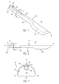
FIG. 1 is a perspective view of a first example embodiment of a vascular retractor in accordance with the present invention, with an endoscope received therein; -
FIG. 2 is a side view of the vascular retractor ofFIG. 1 , without the endoscope; -
FIGS. 3A and 3B are cross-sections of the retractor ofFIG. 2 , taken along line 3-3, showing alternative embodiments of a channel for receiving an endoscope; -
FIG. 4 is a cross-section of the retractor ofFIG. 2 , taken along line 4-4, showing circumferentially extended edges thereof; -
FIG. 5 is a perspective view of a retractor falling outside the scope ofClaim 1, including a pivotable channel member for receiving an endoscope; -
FIG. 6 is a side view of the retractor ofFIG. 5 ; -
FIG. 7 is a cross-section of the retractor ofFIG. 5 , taken along line 7-7; -
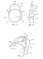
FIG. 8 is a top view of a retractor, including a locking mechanism for holding a light cable or like device; -
FIG. 9 is a side of view of a retractor
falling outside the scope ofClaim 1, including a hooded portion and support legs; -
FIG. 10 is a side of a retractor similar to that ofFigure 9 with a hooded portion, and having an endoscope received therein; -
FIG. 11 is a perspective view of a retractor similar to that offigures 9 and 10 with a hooded portion, including a pivotable finger grip; -
FIG. 12 is a perspective view of an adjustable support device for holding a retractor; -
FIG. 13 is an end view of the adjustable support device ofFIG. 12 ; -
FIG. 14 is a side view of the adjustable support device ofFIG. 12 ; and -
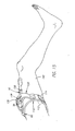
FIG. 15 is a perspective view of an adjustable support device strapped to a patient's leg and holding a retractor similar to that offigures 9 to 11 and endoscope inserted into an incision in the patient's leg. - The following description is directed to a retractor for holding open an anatomic space for performing endoscopic surgical procedures. Generally, the retractor comprises a substantially rigid elongate member, having proximal and distal ends, and having a tunnel or an arcuate, arch shaped or "C" shaped cross-section to hold the dissected space open. The distal end is preferably rounded or streamlined to facilitate insertion along a dissected space with minimal tissue trauma. The cross-section of the elongate member defines a passage therein within the "C" extending distally from the proximal end, and provides a longitudinal working window along the passage between the longitudinal edges of the arch, that is, below the edges of the "C." The elongate member may be fabricated from any metal or plastic material suitable for surgical devices, but preferably is formed from a substantially transparent plastic, such as polycarbonate, to facilitate illumination and/or visualization within the space.
- The elongate member may have a substantially uniform cross-section along its length, or it may be gradually tapered to suit particular applications where the anatomy of the patient requires large and small ends on the retractor. In addition, the elongate member may be a single formed piece, or it may include a plurality of cooperating segments. For example, the elongate member may include telescoping segments, allowing the length of the elongate member to be adjusted. Alternatively, the elongate member may include radially cooperating segments capable of being manipulated to increase or decrease the periphery of the arch, thereby adjusting the cross-sectional area of the anatomic space held open by the retractor.
- The elongate member need not have a uniform cross-section along its entire length. The edges of the "C" cross-section may only extend to a maximum periphery intermittently such that elsewhere along the length of the elongate member there is a greater degree of tissue exposure, hence greater working access to tissue. Preferably, the section of maximum peripheral extension is near the distal end of the elongate member. If so constructed, the self-retaining effect is gained for a substantial length adjacent the section of maximum peripheral extension.
- The retractor also may include a handle formed on or attached to the proximal end of the elongate member. A handle may be attached to the elongate member, for example substantially perpendicular to the longitudinal axis of the elongate member, to facilitate directing the retractor along the dissected space. In addition, the handle may include one or more finger grips pivotally attached to the proximal end of the elongate member to accommodate use with either the left or right hand of the surgeon performing the procedure.
- Alternatively, a curved handle may be attached to or integrally formed on the proximal end, extending proximally therefrom and curving up and away from the passage defined by the elongate member. The handle may comprise an arch-shaped or curved proximal region that extends proximally from a straight distal region of the retractor. Such a curved handle or proximal region may hold open the incision accessing the dissected space, thereby facilitating insertion of the tools used to perform the intended procedure.
- In addition, the retractor may also include a channel for an endoscope, a light source, or similar visualization apparatus. The channel need not extend the full length of the retractor, and may even be a ring. The endoscope channel may be integrally formed along an inside surface of the elongate member. For example, the endoscope channel may be defined by a "C"-shaped member integrally formed along the top of the arch and extending distally from the proximal end.
In certain embodiments, the endoscope channel may be pivotally attached to the elongate member. For example, a cylindrical sleeve, defining the endoscope channel therein, may be attached to the inside surface of the elongate member. The sleeve may include a tab extending therefrom that may be inserted into a similarly shaped hole or slot in the wall of the elongate member. The cooperating tab and hole frictionally engage one another, holding the sleeve in place. If the tab and hole are substantially round, they may also allow the sleeve, and consequently an endoscope inserted therein, to be pivoted about an axis defined by the tab and hole. Alternatively, the sleeve may be substantially permanently fixed to the elongate member, for example by force-fitting the tab into the hole, or by using suitable adhesives. - The retractor may also include an enclosed distal end or hooded portion. A hooded portion may be integrally formed on the distal end of the elongate member or a hood may be formed from a separate component attached to the elongate member. The hooded portion substantially encloses the distal end of the elongate member and includes a rounded distal surface, thereby facilitating insertion along a dissected space with minimal tissue trauma. The hooded portion may have a width comparable to the width of the elongate member, or may have a larger width to provide a wider anatomic space, and therefore a wider working window within the hooded portion. The hooded portion may also be substantially transparent, allowing illumination and/or visualization distally therethrough to monitor insertion of the retractor along the dissected space.
- The retractor may include other features as well. The retractor may include a light source built into the elongate member to provide illumination along the working window to aid in visualization. Alternatively, the proximal end may include a notched slot or other locking detents for holding a cable for a light source inserted into the passage. The proximal end may include a stand, such as a bipod, to help support the retractor and hold open the incision and/or the dissected space. A proximal portion of the elongate member may include an elongate slot, for adjustably connecting the retractor to a support arch which may be attached to the patient adjacent the site of the incision.
- Turning now to the drawings,
FIGS. 1 and 2 show an example embodiment of avascular retractor 10 in accordance with the present invention. Theretractor 10 includes anelongate member 12, ahandle 30, and anendoscope channel 40. Theelongate member 12 has aproximal end 14, adistal end 16, and an arcuate or "C" cross-section, as shown inFIGS. 3A and 3B . The arcuate cross-section may define a portion of the periphery of a circle or an ellipse. Thedistal end 16 is preferably rounded or streamlined to minimize tissue trauma when theretractor 10 is directed along a dissected space in a patient (not shown). Theelongate member 12 defines apassage 18 therein extending distally from theproximal end 14, and includes a longitudinal workingwindow 20 along thepassage 18 between thelongitudinal edges 22 of theelongate member 12. Theelongate member 12 may be fabricated from any suitable metal or plastic material, but preferably is formed from a substantially transparent plastic, such as polycarbonate. - The
elongate member 12 includes circumferentially extended edges orcurved tabs 24 integrally formed along a portion of theedges 22 of theelongate member 12 and extending peripherally from theedges 22, thereby defining anextended periphery 26, as shown inFIG. 4 . The extended edges 24 increase the anatomic space held open by theretractor 10 since the extended periphery further tents the anatomic space, particularly at the location adjacent the extended edges 24. Although theextended edges 24 are shown located on adistal region 28 of theelongate member 12, alternatively they may be located at any predetermined location along theelongate member 12. Furthermore, one or more additional sets of extended edges (not shown) may be provided in other regions of theelongate member 12 to further support the anatomic space being held open. - The
elongate member 12 also includes a curved proximal region or substantially rigidcurved handle 30 integrally formed therein. Thehandle 30 extends proximally from a straightdistal region 15 and curves up and away from thepassage 18, the curvedouter surface 32 being adapted to hold open or "tent" the incision (not shown) into which theretractor 10 is inserted, thereby facilitating introduction of surgical instruments for performing endoscopic procedures within the space held open by theretractor 10. - In addition, the
retractor 10 also includes achannel member 40 for receiving anendoscope 60, having an arbitrary length extending along a portion of theelongate member 12. Alternatively, a light source or other visualization apparatus (not shown) having a diameter similar to an endoscope may be received by thechannel member 40. As shown inFIGS. 3A and 3B , thechannel member 40 is integrally formed along aninside surface 34 of theelongate member 12, thereby defining achannel 42 for receiving an endoscope (not shown inFIGS. 3A and 3B). FIG. 3A shows thechannel member 40 as comprising acylindrical sleeve 44 defining thechannel 42, whileFIG. 3B , shows a pair of curvedelongate tabs 46 together forming a "C"-shape and defining thechannel 42. Alternatively, as described below, a separate cylindrical sleeve or the like (not shown) may be pivotally attached to theelongate member 12 instead of the integral members shown. - Turning now to
FIGS. 5 and 6 , aretractor 10 is shown that is useful for understanding the present invention but does not fall within the scope ofClaim 1. Theretractor 10 includes a substantially rigidelongate member 12 and achannel member 40. Theelongate member 12 has aproximal end 14 and adistal end 16, and has an arcuate or arch-shaped cross-section, as shown inFIG. 7 . Theproximal end 14 may be held to manipulate theretractor 10 and may be rounded to facilitate gripping theretractor 10, although optionally, a handle (not shown) may also be provided on theproximal end 14. Thedistal end 16 is preferably rounded or streamlined to minimize tissue trauma when theretractor 10 is directed along a dissected space in a patient (not shown). Theelongate member 12 includes apassage 18 therein extending distally from theproximal end 14, defining a longitudinal workingwindow 20 along thepassage 18 between thelongitudinal edges 22 of theelongate member 12. Theelongate member 12 includes circumferentially extendededges 24 integrally formed along a portion of theedges 22 of theelongate member 12 and extending peripherally from theedges 22. - The
retractor 10 also includes achannel member 40 for receiving an endoscope (not shown). Thechannel member 40 includes acylindrical sleeve 48, defining achannel 42 for receiving an endoscope, which is attachable to aninside surface 34 of theelongate member 12 by acylindrical tab 52 extending from thesleeve 48. Thetab 52 is inserted into a similarly shapedhole 36 in theelongate member 12. The cooperatingtab 52 andhole 36 frictionally engage one another, holding thesleeve 48 in place. Because thetab 52 andhole 36 are substantially round, thesleeve 48 may be pivoted about anaxis 54. Consequently, an endoscope inserted into thesleeve 48 may also be pivoted laterally, thereby providing an increased field of view. Alternatively, thesleeve 48 may be substantially permanently fixed to theelongate member 12, for example by force-fitting thetab 52 into thehole 36, or by using suitable adhesives. In the case of substantially permanent attachment, thetab 52 andhole 36 may have a number of possible configurations that sufficiently cooperate, for example an elongate tab and slot (not shown). - As shown in
FIG. 8 , theretractor 10 may include lockingdetents 70 or other locking mechanisms, for example, on theproximal end 14, to hold a cable for a light or other instrument (not shown) that may be inserted into the anatomic space held open by theretractor 10. Preferably, thedetents 70 are formed by anelongate slot 72 extending distally from theproximal end 14, and including a plurality of receivingregions 74 adapted to frictionally grip a cable inserted into theelongate slot 72. The detents may substantially fix the cable, minimizing obstruction within the anatomic space that could interfere with instruments inserted therein. - Turning now to
FIGS. 9-11 , aretractor 10 useful for understanding the present invention, although not falling within the scope ofClaim 1, is shown.
Similar to the previously described configuration, theretractor 10 includes a substantially rigidelongate member 12 having aproximal end 14, adistal end 16, and an arcuate cross-section defining apassage 18. In this configuration, theelongate member 12 also includes ahooded region 80 substantially enclosing thepassage 18 at thedistal end 16 of theelongate member 12. Preferably, thehooded region 80 is integrally formed on theelongate member 12, although alternatively, a separate hooded member (not shown) may be attached to theelongate member 12. - The
hooded region 80 has a substantially roundeddistal surface 82 to minimize tissue trauma when theretractor 10 is directed along a dissected space. In addition, thedistal surface 82 is preferably substantially transparent, thereby allowing illumination and/or visualization through thedistal surface 82 of thehooded region 80 of surrounding tissues when theretractor 10 is directed along the dissected space. - The
hooded region 80 also includes circumferentially extendededges 84 integrally formed along thelongitudinal edges 22 of theelongate member 12 and extending peripherally from theedges 22, thereby defining an extended periphery to increase the anatomic space held open by thehooded region 80. The extended edges 84 may extend all along the edge 86 of thedistal surface 82, thereby substantially enclosing thepassage 18 at thedistal end 16, or theedges 84 may be interrupted. For example, a recessed region, such as a tunnel or notch, may be provided at thedistal end 16 of thehooded region 80 to accommodate a blood vessel or other tissue structure (not shown). The tunnel allows a structure therein to be accessed from within thehooded portion 80 without imposing an undesirable load directly onto the structure. Thehooded region 80 may have a width comparable to the other portions of theelongate member 12, or may have a larger width to create a wider working window (not shown) covered by thehooded region 80. - The
retractor 10 also includes afinger grip 92, to facilitate manipulation of theretractor 10 and/or theendoscope 60 received therein. Preferably, thefinger grip 92 includes a substantially rigidcurved handle 94 for being engaged by one or more fingers, although alternatively a ring or a straight handle (not shown) may also be provided. Thehandle 94 may be fixed to theproximal end 14 or, preferably, it may be pivotally attached thereto. For example, as shown inFIG. 11 , thehandle 94 may be mounted on asleeve 96 that may rotate radially in relation to theelongate member 12, thereby allowing thefinger grip 92 to accommodate both a left hand and a right hand. Alternatively, theelongate member 12 andfinger grip 92 may include a cooperating slot and tab or other device (not shown) that allows rotation. - In addition, as shown in
FIG. 9 , theelongate member 12 may include additional support members or a stand, such as thelegs 90 which together provide a bipod, for elevating theproximal end 14 of theretractor 10, for example at a predetermined height above the surface of a patient's leg. Thelegs 90 are preferably detachable from theelongate member 12, such as by snaps or tabs, allowing thelegs 90 to be attached only when needed to tent the incision and facilitate the introduction of instruments into thepassage 18. - To facilitate use of a retractor, an adjustable support device may be provided to hold open or tent the incision into which the retractor is inserted and adjust the orientation of the retractor. For example,
FIGS. 12-15 show such asupport device 100 for use with aretractor 10. Thesupport device 100 generally includes afastening mechanism 110 for attaching the device, for example to a patient's leg 140 (FIG. 15 ), and asupport arch 120. Thefastening mechanism 110 includes a pair ofstraps 112 that may be wrapped around a leg, and a hook and eye (e.g. Velcro®)fastener 114 for securing thestraps 112. Alternatively, thefastening mechanism 110 may include ties, notch and pin belts, adhesive tapes or similar mechanical fasteners (not shown) that may securely hold thesupport arch 120 in a fixed relationship to the site of the surgical procedure. - The
support arch 120 is a substantially rigidarch member 122 attached to thefastening mechanism 110 at thebase 124 of thearch member 122, for example bytabs 126 that may be stitched, glued, riveted or otherwise fastened to thestraps 112. Thearch member 122 includes anelongate slot 128 extending radially along thearch member 122. Aconnector 130, such as a threaded rod with locking nuts, is provided that may travel in theslot 128. Theconnector 130 may be fixed in a desired position along theslot 128 by loosening, adjusting, and tightening theconnector 130. A retractor 10 (FIG. 15 ) may be attached to theconnector 130, for example by anelongate slot 78, which allows theretractor 10 to be adjusted axially in relation to theincision 150 into which theretractor 10 is introduced. - The
support device 100 may be provided from a variety of materials. For example, thestraps 112 may be formed from fabric or flexible plastic tape. Thesupport arch 120 may be made from substantially rigid materials, such as metal or engineered plastic, that provide sufficient support to hold a retractor attached thereto in a fixed position. - Thus, the
retractor 10 may be inserted into theincision 150, and connected to thesupport device 100, for example, to hold theincision 150 open to facilitate introduction of surgical instruments therein. As desired during a procedure, theconnector 130 may be loosened, allowing theretractor 10 to be adjusted proximally, distally, or laterally, and then may be fixed in a new position. - In another configuration, the retractor may be provided from a single piece of resilient, semi-rigid material, allowing the periphery to be minimized when the retractor is directed into and out of the anatomic space. For example, the longitudinal edges of the retractor may be rolled or compressed together, for example into a relatively small diameter cylinder, to facilitate the introduction of the retractor into a dissected space. Once in position, the elongate member may be released, and the edges may resiliently expand until the retractor assumes its arcuate or "C" shape, thereby holding the space open. Alternatively, only a distal-most portion of the retractor may be furnished from a resilient, semi-rigid material, that may be compressed to facilitate introduction of the retractor, while the remaining portion may be formed from a substantially rigid material as previously described.
- To facilitate performance of an endoscopic procedure, optionally, any of the embodiments of the retractor described herein may also include a built-in light source (not shown) to illuminate the
passage 18 and/or the workingwindow 20 to enhance visualization. In addition, aretractor 10 may include one or more notches extending up from thelongitudinal edges 22 of theretractor 10. For example the notches may extend along a region of theretractor 10 to better expose side branches extending laterally from the workingwindow 20, such as a tributary vein that may feed into a vein being harvested. - A principal feature of a retractor in accordance with the present invention is providing a self-supporting device capable of holding open an anatomic space for endoscopic surgery. Conventional methods may be used to create an incision and dissect an anatomic space, for example for endoscopic vein harvesting in a patient's leg. For example,
U.S. Patent No. 5,601,581, issued to Fogarty et al. , discloses an apparatus and method suitable for dissecting an anatomic space. To summarize, a section of a tissue structure, for example a nerve or vein, especially the saphenous vein, is selected to be harvested. An incision is created at a location adjacent to one end of the selected structure, such as at the groin or knee. A tunneling instrument, such as a blunt or soft-tipped dissector including an inflatable balloon thereon, is inserted into the incision and advanced along between tissue layers to identify the selected structure, and then is advanced along the anterior surface of the structure to create a small tunnel. The balloon is inflated to enlarge the tunnel and may be used to dissect fat and skin overlying the structure to develop a tunnel of a desired size. The balloon is then deflated, and the tunneling instrument is removed from the dissected space. - A retractor in accordance with the present invention may then be inserted into the incision and directed along the dissected space while orienting the longitudinal working window towards the structure . An endoscope may be inserted into the passage and retained by the channel member of the retractor, thereby allowing visualization of the space and along the working window. The arcuate shape of the described configurations allow the tissues anterior to the surgical site, such as the tissues anterior to the saphenous vein, to be held up and away from the site without needing external support. The longitudinal edges of the arcuate retractor abut the subcutaneous tissues adjacent the anterior surface of the selected structure, the longitudinal working window defined by the edges providing access along a desired length, for example of the vein being harvested.
Surgical instruments may be introduced into the incision and directed along the passage defined by the retractor to any point along the length of the working window without having to relocate the retractor, for example to perform an endoscopic vein harvesting procedure. If a pivotable channel member is provided on the retractor, the endoscope may be pivoted, as well as being directed axially, to observe the procedure being performed within the space. Thus, a retractor in accordance with the present invention may allow a vein, nerve or similar elongate tissue structure to be harvested without having to relocate the retractor during the procedure. - While the invention is susceptible to various modifications, and alternative forms, specific examples thereof have been shown in the drawings and are herein described in detail. It should be understood, however, that the invention is not to be limited to the particular forms disclosed, but to the contrary, the invention is to cover all modifications, equivalents and alternatives falling within the scope of the appended claims.
Claims (7)
- A retractor (10) for holding open an anatomic space developed in a patient for performing an endoscopic procedure therein, said retractor comprising:a substantially rigid elongate member (12) having proximal (14) and distal (16) ends, said elongate member having a generally arcuate cross-section defining a passage (18) therein between longitudinal edges (22), wherein said elongate member (12) is provided with circumferentially extended edges formed along a portion of the edges (22) and wherein said extended edges comprise tabs (24) integrally formed in said elongate member and extending peripherally from the edges (22), thereby defining an extended periphery (26) for increasing the anatomic space to be held open adjacent the extended edges (24); andan endoscope channel (42), said channel being on an inside surface (34) of said elongate member, and extending distally along a portion thereof, characterized in that:said elongate member includes a curved proximal region which curves up and away from said passage (18) to define a curved outer surface (32), the curved outer surface (32) being adapted to hold open or tent an anatomic space developed in a patient, and facilitating insertion of instruments into the passage (18).
- The retractor of claim 1, wherein said extended edges (24) are in a distal region of said elongate member.
- The retractor of claim 2, comprising additional extended edges in a region of said elongate member (12) proximate to said extended edges (24) in said distal region.
- The retractor of claim 1, 2 or 3, wherein said endoscope channel (42) is integrally formed along said inside surface (34) of said elongate member (12).
- The retractor of any preceding claim, wherein said endoscope channel comprises a "C"-shaped channel member (40) defining the channel (42) therein for slidably receiving an endoscope.
- The retractor of any preceding claim, wherein said distal end (16) includes a substantially rounded distal end to facilitate insertion of said retractor (10) into a dissected space in a patient.
- The retractor of any preceding claim, wherein said retractor comprises substantially transparent plastic.
Applications Claiming Priority (2)
| Application Number | Priority Date | Filing Date | Title |
|---|---|---|---|
| US08/867,133 US6033361A (en) | 1997-06-02 | 1997-06-02 | Vascular retractor |
| EP98923814A EP0986329B1 (en) | 1997-06-02 | 1998-05-27 | Vascular retractor |
Related Parent Applications (2)
| Application Number | Title | Priority Date | Filing Date |
|---|---|---|---|
| EP98923814.2 Division | 1998-05-27 | ||
| EP98923814A Division EP0986329B1 (en) | 1997-06-02 | 1998-05-27 | Vascular retractor |
Publications (3)
| Publication Number | Publication Date |
|---|---|
| EP1690498A2 EP1690498A2 (en) | 2006-08-16 |
| EP1690498A3 EP1690498A3 (en) | 2006-08-23 |
| EP1690498B1 true EP1690498B1 (en) | 2010-09-29 |
Family
ID=25349169
Family Applications (2)
| Application Number | Title | Priority Date | Filing Date |
|---|---|---|---|
| EP98923814A Expired - Lifetime EP0986329B1 (en) | 1997-06-02 | 1998-05-27 | Vascular retractor |
| EP06009549A Expired - Lifetime EP1690498B1 (en) | 1997-06-02 | 1998-05-27 | Retractor for endoscopic surgery |
Family Applications Before (1)
| Application Number | Title | Priority Date | Filing Date |
|---|---|---|---|
| EP98923814A Expired - Lifetime EP0986329B1 (en) | 1997-06-02 | 1998-05-27 | Vascular retractor |
Country Status (8)
| Country | Link |
|---|---|
| US (1) | US6033361A (en) |
| EP (2) | EP0986329B1 (en) |
| JP (1) | JP2002502292A (en) |
| AT (2) | ATE449569T1 (en) |
| CA (1) | CA2291702C (en) |
| DE (2) | DE69841310D1 (en) |
| ES (2) | ES2336391T3 (en) |
| WO (1) | WO1998055029A1 (en) |
Families Citing this family (37)
| Publication number | Priority date | Publication date | Assignee | Title |
|---|---|---|---|---|
| US6196968B1 (en) * | 1997-06-02 | 2001-03-06 | General Surgical Innovations, Inc. | Direct vision subcutaneous tissue retractor and method for use |
| US5913818A (en) * | 1997-06-02 | 1999-06-22 | General Surgical Innovations, Inc. | Vascular retractor |
| US6200263B1 (en) | 1998-01-23 | 2001-03-13 | United States Surgical Corporation | Surgical instrument holder |
| US6228025B1 (en) | 1998-05-01 | 2001-05-08 | Genzyme Corporation | Illuminated saphenous vein retractor |
| DE19827360C2 (en) * | 1998-06-19 | 2000-05-31 | Storz Karl Gmbh & Co Kg | Medical instrument for endoscopic removal of the saphenous vein |
| US6648815B2 (en) | 1998-06-19 | 2003-11-18 | Karl Storz Gmbh & Co. Kg | Medical instrument and method for endoscopic removal of the saphenous vein |
| US6585727B1 (en) | 1999-10-22 | 2003-07-01 | Genzyme Corporation | Surgical instrument light source and surgical illumination method |
| US6322499B1 (en) * | 2000-01-20 | 2001-11-27 | Genzyme Corporation | Pivotal and illuminated saphenous vein retractor |
| US6497654B1 (en) | 2000-02-18 | 2002-12-24 | Genzyme Corporation | Illuminated rectal retractor |
| US6428473B1 (en) | 2000-02-18 | 2002-08-06 | Genzyme Corporation | Illuminated rectal retractor |
| US6554768B1 (en) | 2000-09-05 | 2003-04-29 | Genzyme Corporation | Illuminated deep pelvic retractor |
| US7137949B2 (en) * | 2001-07-13 | 2006-11-21 | United States Surgical Corporation | Surgical instrument |
| US6817978B2 (en) | 2002-01-23 | 2004-11-16 | Teleflex-Ct Devices Incorporated | Illuminated retractor for use in connection with harvesting a blood vessel from the arm |
| US6805666B2 (en) | 2002-05-23 | 2004-10-19 | Donna D. Holland | Pivotal and illuminated saphenous vein retractor with tapered design |
| AU2003282729B2 (en) * | 2002-10-02 | 2009-05-07 | Synthes (U.S.A) | Retractor with interchangeable retractor blades |
| US20050070949A1 (en) * | 2002-12-20 | 2005-03-31 | Bakos Gregory J. | Transparent dilator device and method of use |
| US7309344B2 (en) * | 2002-12-20 | 2007-12-18 | Ethicon Endo-Surgery, Inc. | Transparent dilator device and method of use |
| US7846171B2 (en) | 2004-05-27 | 2010-12-07 | C.R. Bard, Inc. | Method and apparatus for delivering a prosthetic fabric into a patient |
| US7762951B2 (en) * | 2004-06-25 | 2010-07-27 | Medtronic, Inc. | Vein harvesting system including dilator shaft and removable retractor housing |
| US8409088B2 (en) * | 2006-01-18 | 2013-04-02 | Invuity, Inc. | Retractor illumination system |
| US8047987B2 (en) | 2006-05-26 | 2011-11-01 | Invuity, Inc. | Blade insert illuminator |
| WO2008035384A1 (en) * | 2006-09-21 | 2008-03-27 | Thd S.P.A. | A device for examinig and surgically operating on body cavities, in particular the anal and vaginal cavities |
| KR100828135B1 (en) * | 2006-12-13 | 2008-05-08 | 이은규 | Endoscopic dissector |
| US8075575B2 (en) * | 2007-08-14 | 2011-12-13 | Toby Orthopaedics, Llc | Device and method for assisting in flexor tendon repair and rehabilitation |
| US8088066B2 (en) | 2007-10-24 | 2012-01-03 | Invuity, Inc. | Blade insert illuminator |
| AU2008340311B2 (en) * | 2007-12-21 | 2014-12-18 | Smith & Nephew, Inc. | Cannula |
| GB0800835D0 (en) | 2008-01-17 | 2008-02-27 | Cardioprec Ltd | Retractor |
| US11382711B2 (en) | 2008-08-13 | 2022-07-12 | Invuity, Inc. | Cyclo olefin polymer and copolymer medical devices |
| AU2009293295A1 (en) | 2008-09-16 | 2010-03-25 | Toby Orthopaedics, Inc. | Suture retriever-sheath dilator tool and method for use thereof |
| US20150173733A1 (en) | 2010-07-29 | 2015-06-25 | Greatbatch Ltd. | Retractor Tool For Minimally Invasive Hip Replacement Surgery |
| GB201015746D0 (en) | 2010-09-21 | 2010-10-27 | Cardioprec Ltd | Optical switch |
| WO2012142482A1 (en) * | 2011-04-13 | 2012-10-18 | Curax, Llc | Multi-function cannulated surgical device |
| WO2013033634A1 (en) | 2011-09-01 | 2013-03-07 | Toby Orthopaedics, Llc | Tendon crimp for passage into a bone tunnel and method for use thereof |
| US10433960B1 (en) | 2015-05-07 | 2019-10-08 | Cardioprecision Limited | Method and system for transcatheter intervention |
| BR112019021267A2 (en) | 2017-04-18 | 2020-05-19 | Edwards Lifesciences Corp | heart valve sealing devices and release devices |
| US10959846B2 (en) | 2017-05-10 | 2021-03-30 | Edwards Lifesciences Corporation | Mitral valve spacer device |
| EP3996578A4 (en) | 2019-07-11 | 2023-07-26 | Teh, Kok Kheng | An endoscopic-release surgical retractor |
Family Cites Families (28)
| Publication number | Priority date | Publication date | Assignee | Title |
|---|---|---|---|---|
| US516842A (en) * | 1894-03-20 | Wtlhelm scheerer | ||
| US659182A (en) * | 1900-05-21 | 1900-10-02 | George P Pilling | Retractor. |
| US2082782A (en) * | 1935-10-03 | 1937-06-08 | Alfred G Allen | Vacuum tenaculum |
| US2201331A (en) * | 1938-11-03 | 1940-05-21 | Alfred G Wright | Mouth prop and light carrier |
| US2575253A (en) * | 1949-05-16 | 1951-11-13 | Joseph F Bicek | Vaginal speculum |
| US2653597A (en) * | 1949-12-09 | 1953-09-29 | Walter T Canan | Tongue depressor and mirror therefor |
| US2812758A (en) * | 1955-07-26 | 1957-11-12 | John C Blumenschein | Surgical retractor |
| US2829649A (en) * | 1956-01-17 | 1958-04-08 | Robert J Glenner | Hemostat-retractor |
| US3509873A (en) * | 1967-04-24 | 1970-05-05 | Jack B Karlin | Retractor |
| US3570475A (en) * | 1968-11-14 | 1971-03-16 | Mandel Weinstein | Surgical retractor |
| US3651800A (en) * | 1970-05-15 | 1972-03-28 | James L Wilbanks | Surgical instrument |
| US3851642A (en) * | 1971-10-26 | 1974-12-03 | Medical Testing Syst Inc | Medical examining instrument |
| US3796214A (en) * | 1972-12-04 | 1974-03-12 | R Davis | Perineal retractor |
| US4232660A (en) * | 1979-03-26 | 1980-11-11 | Coles Robert L | Winged irrigating surgical retractor |
| US4380999A (en) * | 1980-07-15 | 1983-04-26 | Healy Keelin E | Stepped surgical retractor |
| US4934352A (en) * | 1982-10-22 | 1990-06-19 | Sullivan Jr Eugene M | Surgical retractor handle construction |
| US4562832A (en) * | 1984-01-21 | 1986-01-07 | Wilder Joseph R | Medical instrument and light pipe illumination assembly |
| US4686972A (en) * | 1986-04-30 | 1987-08-18 | Kurland Kenneth Z | Surgical deflector and drilling guide |
| US5345927A (en) * | 1990-03-02 | 1994-09-13 | Bonutti Peter M | Arthroscopic retractors |
| FR2662929A1 (en) * | 1990-06-08 | 1991-12-13 | Berlinski Michel | Surgical instrument of the retractor or vaginal retractor type |
| US5192286A (en) * | 1991-07-26 | 1993-03-09 | Regents Of The University Of California | Method and device for retrieving materials from body lumens |
| US5431153A (en) * | 1993-06-11 | 1995-07-11 | Lee; Hans | Surgical apparatus for assisting in the release of the carpal tunnel |
| US5601581A (en) | 1995-05-19 | 1997-02-11 | General Surgical Innovations, Inc. | Methods and devices for blood vessel harvesting |
| US5759150A (en) * | 1995-07-07 | 1998-06-02 | Olympus Optical Co., Ltd. | System for evulsing subcutaneous tissue |
| JP3053566B2 (en) * | 1995-07-07 | 2000-06-19 | オリンパス光学工業株式会社 | Cavity securing tool |
| US5667480A (en) * | 1995-10-20 | 1997-09-16 | Ethicon Endo-Surgery, Inc. | Method and devices for endoscopic vessel harvesting |
| US5782753A (en) * | 1995-10-20 | 1998-07-21 | United States Surgical Corporation | Surgical retractor |
| ES2224228T3 (en) * | 1996-03-22 | 2005-03-01 | Sdgi Holdings, Inc. | DEVICE FOR PERCUTANEOUS SURGERY. |
-
1997
- 1997-06-02 US US08/867,133 patent/US6033361A/en not_active Expired - Lifetime
-
1998
- 1998-05-27 ES ES98923814T patent/ES2336391T3/en not_active Expired - Lifetime
- 1998-05-27 DE DE69841310T patent/DE69841310D1/en not_active Expired - Lifetime
- 1998-05-27 CA CA002291702A patent/CA2291702C/en not_active Expired - Fee Related
- 1998-05-27 JP JP50255999A patent/JP2002502292A/en active Pending
- 1998-05-27 AT AT98923814T patent/ATE449569T1/en not_active IP Right Cessation
- 1998-05-27 WO PCT/US1998/010793 patent/WO1998055029A1/en active Application Filing
- 1998-05-27 DE DE69841922T patent/DE69841922D1/en not_active Expired - Lifetime
- 1998-05-27 ES ES06009549T patent/ES2352416T3/en not_active Expired - Lifetime
- 1998-05-27 AT AT06009549T patent/ATE482653T1/en not_active IP Right Cessation
- 1998-05-27 EP EP98923814A patent/EP0986329B1/en not_active Expired - Lifetime
- 1998-05-27 EP EP06009549A patent/EP1690498B1/en not_active Expired - Lifetime
Also Published As
| Publication number | Publication date |
|---|---|
| CA2291702A1 (en) | 1998-12-10 |
| EP0986329A1 (en) | 2000-03-22 |
| ES2352416T3 (en) | 2011-02-18 |
| ATE482653T1 (en) | 2010-10-15 |
| DE69841310D1 (en) | 2010-01-07 |
| WO1998055029A1 (en) | 1998-12-10 |
| EP0986329A4 (en) | 2001-11-21 |
| DE69841922D1 (en) | 2010-11-11 |
| EP1690498A3 (en) | 2006-08-23 |
| ES2336391T3 (en) | 2010-04-12 |
| ATE449569T1 (en) | 2009-12-15 |
| EP1690498A2 (en) | 2006-08-16 |
| US6033361A (en) | 2000-03-07 |
| JP2002502292A (en) | 2002-01-22 |
| CA2291702C (en) | 2004-07-20 |
| EP0986329B1 (en) | 2009-11-25 |
Similar Documents
| Publication | Publication Date | Title |
|---|---|---|
| EP1690498B1 (en) | Retractor for endoscopic surgery | |
| EP1011467B1 (en) | Vascular retractor | |
| US6196968B1 (en) | Direct vision subcutaneous tissue retractor and method for use | |
| US5928138A (en) | Method and devices for endoscopic vessel harvesting | |
| US5722934A (en) | Method and devices for endoscopoic vessel harvesting | |
| US5938680A (en) | Devices and methods for harvesting vascular conduits | |
| US6042538A (en) | Device for endoscopic vessel harvesting | |
| CA2350101C (en) | Apparatus and method for dissecting and retracting elongate structures | |
| US20040186353A1 (en) | Vascular retractor and methods of using same | |
| AU2002355439A1 (en) | Retractor for vasculary surgery, and methods of use | |
| WO1999025238A2 (en) | Device for endoscopic vessel harvesting | |
| CA2537342C (en) | Method and devices for endoscopic vessel harvesting | |
| AU776480B2 (en) | Illuminated surgical retractor | |
| WO2000071033A1 (en) | Refractor apparatus for use in harvesting mammary arteries during heart by-pass surgery |
Legal Events
| Date | Code | Title | Description |
|---|---|---|---|
| PUAI | Public reference made under article 153(3) epc to a published international application that has entered the european phase |
Free format text: ORIGINAL CODE: 0009012 |
|
| PUAL | Search report despatched |
Free format text: ORIGINAL CODE: 0009013 |
|
| 17P | Request for examination filed |
Effective date: 20060509 |
|
| AC | Divisional application: reference to earlier application |
Ref document number: 0986329 Country of ref document: EP Kind code of ref document: P |
|
| AK | Designated contracting states |
Kind code of ref document: A2 Designated state(s): AT BE CH CY DE DK ES FI FR GB GR IE IT LI LU MC NL PT SE |
|
| AK | Designated contracting states |
Kind code of ref document: A3 Designated state(s): AT BE CH CY DE DK ES FI FR GB GR IE IT LI LU MC NL PT SE |
|
| RIN1 | Information on inventor provided before grant (corrected) |
Inventor name: CO, FRED H. Inventor name: VAN BLADEL, KEVIN H. |
|
| 17Q | First examination report despatched |
Effective date: 20070103 |
|
| AKX | Designation fees paid |
Designated state(s): AT BE CH CY DE DK ES FI FR GB GR IE IT LI LU MC NL PT SE |
|
| RTI1 | Title (correction) |
Free format text: RETRACTOR FOR ENDOSCOPIC SURGERY |
|
| GRAP | Despatch of communication of intention to grant a patent |
Free format text: ORIGINAL CODE: EPIDOSNIGR1 |
|
| GRAS | Grant fee paid |
Free format text: ORIGINAL CODE: EPIDOSNIGR3 |
|
| GRAA | (expected) grant |
Free format text: ORIGINAL CODE: 0009210 |
|
| AC | Divisional application: reference to earlier application |
Ref document number: 0986329 Country of ref document: EP Kind code of ref document: P |
|
| AK | Designated contracting states |
Kind code of ref document: B1 Designated state(s): AT BE CH CY DE DK ES FI FR GB GR IE IT LI LU MC NL PT SE |
|
| REG | Reference to a national code |
Ref country code: GB Ref legal event code: FG4D |
|
| REG | Reference to a national code |
Ref country code: CH Ref legal event code: EP |
|
| REG | Reference to a national code |
Ref country code: IE Ref legal event code: FG4D |
|
| REF | Corresponds to: |
Ref document number: 69841922 Country of ref document: DE Date of ref document: 20101111 Kind code of ref document: P |
|
| PG25 | Lapsed in a contracting state [announced via postgrant information from national office to epo] |
Ref country code: AT Free format text: LAPSE BECAUSE OF FAILURE TO SUBMIT A TRANSLATION OF THE DESCRIPTION OR TO PAY THE FEE WITHIN THE PRESCRIBED TIME-LIMIT Effective date: 20100929 Ref country code: FI Free format text: LAPSE BECAUSE OF FAILURE TO SUBMIT A TRANSLATION OF THE DESCRIPTION OR TO PAY THE FEE WITHIN THE PRESCRIBED TIME-LIMIT Effective date: 20100929 |
|
| REG | Reference to a national code |
Ref country code: NL Ref legal event code: VDEP Effective date: 20100929 |
|
| REG | Reference to a national code |
Ref country code: ES Ref legal event code: FG2A Effective date: 20110208 |
|
| PG25 | Lapsed in a contracting state [announced via postgrant information from national office to epo] |
Ref country code: SE Free format text: LAPSE BECAUSE OF FAILURE TO SUBMIT A TRANSLATION OF THE DESCRIPTION OR TO PAY THE FEE WITHIN THE PRESCRIBED TIME-LIMIT Effective date: 20100929 Ref country code: GR Free format text: LAPSE BECAUSE OF FAILURE TO SUBMIT A TRANSLATION OF THE DESCRIPTION OR TO PAY THE FEE WITHIN THE PRESCRIBED TIME-LIMIT Effective date: 20101230 |
|
| PG25 | Lapsed in a contracting state [announced via postgrant information from national office to epo] |
Ref country code: NL Free format text: LAPSE BECAUSE OF FAILURE TO SUBMIT A TRANSLATION OF THE DESCRIPTION OR TO PAY THE FEE WITHIN THE PRESCRIBED TIME-LIMIT Effective date: 20100929 Ref country code: PT Free format text: LAPSE BECAUSE OF FAILURE TO SUBMIT A TRANSLATION OF THE DESCRIPTION OR TO PAY THE FEE WITHIN THE PRESCRIBED TIME-LIMIT Effective date: 20110131 |
|
| PG25 | Lapsed in a contracting state [announced via postgrant information from national office to epo] |
Ref country code: BE Free format text: LAPSE BECAUSE OF FAILURE TO SUBMIT A TRANSLATION OF THE DESCRIPTION OR TO PAY THE FEE WITHIN THE PRESCRIBED TIME-LIMIT Effective date: 20100929 |
|
| PLBE | No opposition filed within time limit |
Free format text: ORIGINAL CODE: 0009261 |
|
| STAA | Information on the status of an ep patent application or granted ep patent |
Free format text: STATUS: NO OPPOSITION FILED WITHIN TIME LIMIT |
|
| PG25 | Lapsed in a contracting state [announced via postgrant information from national office to epo] |
Ref country code: DK Free format text: LAPSE BECAUSE OF FAILURE TO SUBMIT A TRANSLATION OF THE DESCRIPTION OR TO PAY THE FEE WITHIN THE PRESCRIBED TIME-LIMIT Effective date: 20100929 |
|
| REG | Reference to a national code |
Ref country code: DE Ref legal event code: R097 Ref document number: 69841922 Country of ref document: DE Effective date: 20110630 |
|
| PG25 | Lapsed in a contracting state [announced via postgrant information from national office to epo] |
Ref country code: MC Free format text: LAPSE BECAUSE OF NON-PAYMENT OF DUE FEES Effective date: 20110531 |
|
| REG | Reference to a national code |
Ref country code: CH Ref legal event code: PL |
|
| PG25 | Lapsed in a contracting state [announced via postgrant information from national office to epo] |
Ref country code: LI Free format text: LAPSE BECAUSE OF NON-PAYMENT OF DUE FEES Effective date: 20110531 Ref country code: CH Free format text: LAPSE BECAUSE OF NON-PAYMENT OF DUE FEES Effective date: 20110531 |
|
| PGFP | Annual fee paid to national office [announced via postgrant information from national office to epo] |
Ref country code: ES Payment date: 20120528 Year of fee payment: 15 |
|
| PG25 | Lapsed in a contracting state [announced via postgrant information from national office to epo] |
Ref country code: LU Free format text: LAPSE BECAUSE OF NON-PAYMENT OF DUE FEES Effective date: 20110527 Ref country code: CY Free format text: LAPSE BECAUSE OF FAILURE TO SUBMIT A TRANSLATION OF THE DESCRIPTION OR TO PAY THE FEE WITHIN THE PRESCRIBED TIME-LIMIT Effective date: 20100929 |
|
| PGFP | Annual fee paid to national office [announced via postgrant information from national office to epo] |
Ref country code: IT Payment date: 20130524 Year of fee payment: 16 |
|
| PG25 | Lapsed in a contracting state [announced via postgrant information from national office to epo] |
Ref country code: IT Free format text: LAPSE BECAUSE OF NON-PAYMENT OF DUE FEES Effective date: 20140527 |
|
| REG | Reference to a national code |
Ref country code: ES Ref legal event code: FD2A Effective date: 20150630 |
|
| PG25 | Lapsed in a contracting state [announced via postgrant information from national office to epo] |
Ref country code: ES Free format text: LAPSE BECAUSE OF NON-PAYMENT OF DUE FEES Effective date: 20140528 |
|
| REG | Reference to a national code |
Ref country code: FR Ref legal event code: PLFP Year of fee payment: 19 |
|
| REG | Reference to a national code |
Ref country code: FR Ref legal event code: PLFP Year of fee payment: 20 |
|
| PGFP | Annual fee paid to national office [announced via postgrant information from national office to epo] |
Ref country code: FR Payment date: 20170421 Year of fee payment: 20 Ref country code: DE Payment date: 20170420 Year of fee payment: 20 Ref country code: IE Payment date: 20170421 Year of fee payment: 20 Ref country code: GB Payment date: 20170426 Year of fee payment: 20 |
|
| REG | Reference to a national code |
Ref country code: DE Ref legal event code: R071 Ref document number: 69841922 Country of ref document: DE |
|
| REG | Reference to a national code |
Ref country code: GB Ref legal event code: PE20 Expiry date: 20180526 |
|
| REG | Reference to a national code |
Ref country code: IE Ref legal event code: MK9A |
|
| PG25 | Lapsed in a contracting state [announced via postgrant information from national office to epo] |
Ref country code: IE Free format text: LAPSE BECAUSE OF EXPIRATION OF PROTECTION Effective date: 20180527 Ref country code: GB Free format text: LAPSE BECAUSE OF EXPIRATION OF PROTECTION Effective date: 20180526 |