EP1696245A2 - Method for tracking a detection microchip - Google Patents
Method for tracking a detection microchip Download PDFInfo
- Publication number
- EP1696245A2 EP1696245A2 EP05024992A EP05024992A EP1696245A2 EP 1696245 A2 EP1696245 A2 EP 1696245A2 EP 05024992 A EP05024992 A EP 05024992A EP 05024992 A EP05024992 A EP 05024992A EP 1696245 A2 EP1696245 A2 EP 1696245A2
- Authority
- EP
- European Patent Office
- Prior art keywords
- signal
- detection
- determined
- phase
- distance
- Prior art date
- Legal status (The legal status is an assumption and is not a legal conclusion. Google has not performed a legal analysis and makes no representation as to the accuracy of the status listed.)
- Withdrawn
Links
Images
Classifications
-
- G—PHYSICS
- G01—MEASURING; TESTING
- G01S—RADIO DIRECTION-FINDING; RADIO NAVIGATION; DETERMINING DISTANCE OR VELOCITY BY USE OF RADIO WAVES; LOCATING OR PRESENCE-DETECTING BY USE OF THE REFLECTION OR RERADIATION OF RADIO WAVES; ANALOGOUS ARRANGEMENTS USING OTHER WAVES
- G01S13/00—Systems using the reflection or reradiation of radio waves, e.g. radar systems; Analogous systems using reflection or reradiation of waves whose nature or wavelength is irrelevant or unspecified
- G01S13/74—Systems using reradiation of radio waves, e.g. secondary radar systems; Analogous systems
- G01S13/82—Systems using reradiation of radio waves, e.g. secondary radar systems; Analogous systems wherein continuous-type signals are transmitted
- G01S13/84—Systems using reradiation of radio waves, e.g. secondary radar systems; Analogous systems wherein continuous-type signals are transmitted for distance determination by phase measurement
-
- G—PHYSICS
- G01—MEASURING; TESTING
- G01S—RADIO DIRECTION-FINDING; RADIO NAVIGATION; DETERMINING DISTANCE OR VELOCITY BY USE OF RADIO WAVES; LOCATING OR PRESENCE-DETECTING BY USE OF THE REFLECTION OR RERADIATION OF RADIO WAVES; ANALOGOUS ARRANGEMENTS USING OTHER WAVES
- G01S13/00—Systems using the reflection or reradiation of radio waves, e.g. radar systems; Analogous systems using reflection or reradiation of waves whose nature or wavelength is irrelevant or unspecified
- G01S13/74—Systems using reradiation of radio waves, e.g. secondary radar systems; Analogous systems
- G01S13/75—Systems using reradiation of radio waves, e.g. secondary radar systems; Analogous systems using transponders powered from received waves, e.g. using passive transponders, or using passive reflectors
- G01S13/751—Systems using reradiation of radio waves, e.g. secondary radar systems; Analogous systems using transponders powered from received waves, e.g. using passive transponders, or using passive reflectors wherein the responder or reflector radiates a coded signal
- G01S13/758—Systems using reradiation of radio waves, e.g. secondary radar systems; Analogous systems using transponders powered from received waves, e.g. using passive transponders, or using passive reflectors wherein the responder or reflector radiates a coded signal using a signal generator powered by the interrogation signal
-
- G—PHYSICS
- G01—MEASURING; TESTING
- G01S—RADIO DIRECTION-FINDING; RADIO NAVIGATION; DETERMINING DISTANCE OR VELOCITY BY USE OF RADIO WAVES; LOCATING OR PRESENCE-DETECTING BY USE OF THE REFLECTION OR RERADIATION OF RADIO WAVES; ANALOGOUS ARRANGEMENTS USING OTHER WAVES
- G01S13/00—Systems using the reflection or reradiation of radio waves, e.g. radar systems; Analogous systems using reflection or reradiation of waves whose nature or wavelength is irrelevant or unspecified
- G01S13/87—Combinations of radar systems, e.g. primary radar and secondary radar
- G01S13/878—Combination of several spaced transmitters or receivers of known location for determining the position of a transponder or a reflector
-
- G—PHYSICS
- G01—MEASURING; TESTING
- G01S—RADIO DIRECTION-FINDING; RADIO NAVIGATION; DETERMINING DISTANCE OR VELOCITY BY USE OF RADIO WAVES; LOCATING OR PRESENCE-DETECTING BY USE OF THE REFLECTION OR RERADIATION OF RADIO WAVES; ANALOGOUS ARRANGEMENTS USING OTHER WAVES
- G01S5/00—Position-fixing by co-ordinating two or more direction or position line determinations; Position-fixing by co-ordinating two or more distance determinations
- G01S5/02—Position-fixing by co-ordinating two or more direction or position line determinations; Position-fixing by co-ordinating two or more distance determinations using radio waves
- G01S5/0205—Details
- G01S5/021—Calibration, monitoring or correction
-
- G—PHYSICS
- G01—MEASURING; TESTING
- G01S—RADIO DIRECTION-FINDING; RADIO NAVIGATION; DETERMINING DISTANCE OR VELOCITY BY USE OF RADIO WAVES; LOCATING OR PRESENCE-DETECTING BY USE OF THE REFLECTION OR RERADIATION OF RADIO WAVES; ANALOGOUS ARRANGEMENTS USING OTHER WAVES
- G01S5/00—Position-fixing by co-ordinating two or more direction or position line determinations; Position-fixing by co-ordinating two or more distance determinations
- G01S5/02—Position-fixing by co-ordinating two or more direction or position line determinations; Position-fixing by co-ordinating two or more distance determinations using radio waves
- G01S5/06—Position of source determined by co-ordinating a plurality of position lines defined by path-difference measurements
Definitions
- the invention relates to a method for locating a detector wafer according to the preamble of claim 1.
- Detektierplättchen For identification of goods in warehousing and transport increasingly Detektierplättchen are used, which are each connected to the goods and store unique identification information. By reading the identification information by means of a reader so the goods can be identified.
- detection tiles and readers with a sufficiently large detection area are required for identification. Furthermore, the application of a separation process is necessary. Detector pads and readers that operate on UHF frequencies and above meet the requirements. In this frequency range Both the necessary high range and the necessary high data transmission rate can be realized in order to be able to isolate and simultaneously read all the detection plates simultaneously in the desired detection range in a sufficiently short time.
- the transmitting power and receiving sensitivity of the reading device must be so great that detection plates can be safely read even under unfavorable constellations in the desired detection range.
- the reading field can not be selectively limited to a selected transport or storage units in several adjacent transport or storage units, but also detects adjacent transport or storage units.
- the detection plates connected to the goods must additionally be located after reading and then selected.
- the invention has for its object to provide a method for locating a Detektierplättchens, which allows the detection of at least one location coordinate.
- the invention is based on a detection wafer which emits a detection signal which is received and evaluated by a reading device.
- This can be a passive detector wafer which changes the carrier signal of the reading device in terms of amplitude and / or phase modulation or an active detection wafer whose detection signal comprises a carrier which is generated synchronously with the carrier signal of the reading device.
- runtime-dependent characteristics of the detection signal change on the way from the detection wafer to the reading device.
- the change of the running time is proportional to the distance between the detector plate and the reader.
- the phase and amplitude of the detection signal is evaluated as a delay-dependent feature of the received detection signal.
- the evaluation of the delay-dependent feature can be done in this case after the demodulation required anyway for the data acquisition and thus in a lower frequency range compared to the frequency of the carrier signal.
- the detection pad receives a carrier signal from the reader and emits a detection signal modulated with a modulation signal having the same frequency as the carrier signal.
- the modulation signal has signal points which can be approximated by a straight line in a signal space diagram.
- the detection signal received by the reader is demodulated, the difference of the phase position of the detection signal at a current distance and a reference distance between detector plate and reader is determined and from the difference of the phase position, the carrier frequency and the propagation velocity of the electromagnetic waves, the actual distance between the Detektierplättchen and the reader is determined.
- the modulation signal has signal points that can be approximated by a straight line in a signal space diagram, it is achieved that the phase position of the detection signal is reproducible.
- the transition between the signal points does not have to be approximated by a straight line.
- other modulation types are also applicable in which the signal points in a signal space diagram can be arbitrary.
- the finite speed of propagation of electromagnetic waves results in a time difference between transmission of the detection signal and reception at the reading device, which leads to a difference between the phase position of the carrier signal generated by the reading device and the phase position of the detection signal of the same frequency received by the reading device.
- These Difference of the phase positions is a measure of the distance between the detector plate and the reader.
- the difference in the phase positions also depends on the frequency of the carrier signal, the short wavelengths in the UHF range result in a sufficiently large value for the difference of the phase positions in order to technically realize a distance measurement with a resolution in the cm range.
- Signal propagation times within the reader and detector wafer can be considered constant and do not affect the difference in phase position changes with distance changes.
- the phase angle assumes the same value again after a distance ⁇ / 2.
- the distance ⁇ / 2 results from the fact that the transit time t of the signal comprises both the path from the reading device to the detection plate and the path from the detection plate back to the reading device.
- the difference of the phase positions between a current distance and a reference distance is unique. For a distance> ⁇ / 2, ambiguities N occur, which can be resolved by continuously updating the location of the detector wafer in steps ⁇ / 2.
- the detection pad receives from the reader carrier signals of a first and then at least a second frequency and emits, each with a modulation signal modulated detection signals, each having the same frequency as the carrier signals.
- the modulation signals have signal points that can be approximated by a straight line in a signal space diagram.
- the detection signals received by the reading device are demodulated, the respective phase position of the respective detection signal is determined, and by common evaluation, the actual distance between the detection plate and the reading device is determined from the phase positions, the carrier frequencies and the propagation velocity of the electromagnetic waves.
- the detector wafer can receive carrier signals of a first and at the same time at least one second frequency from the reader and at the same time emit detection signals modulated with a respective modulation signal.
- the detection signals received by the reader are filtered separated and demodulated, the respective phase position of the respective detection signal is determined simultaneously.
- a reference distance is then not required. Sources of interference due to non-long-term effects are eliminated by the difference formation. But it is a higher precision in determining the phase angles necessary.
- the phase angle can also be measured at more than two carrier frequencies in order to resolve these ambiguities.
- the phase position can be determined at least twice with a time interval during the localization period and a change in the phase position at a time interval can be determined as a relative movement between the reader and detector wafer, while a match is determined as a constant distance between the reader and detector wafer.
- a criterion is determined as to whether the reader and the detector plate move relative to each other at a distance or not.
- One possibility for using this criterion is to provide goods provided with detector platelets on a moving transport unit, e.g. As a pallet on a forklift from stationary provided with Detektierplättchen goods, z. B. on pallets on a shelf from each other.
- the speed and / or the direction vector of the movement can be determined from the extent of the change in the distance or the phase position within a time interval.
- the detection signal during the localization period is modulated with a signal which is between at least two states, for. B. A and B, changes.
- the detection signal received by the reading device is decomposed in a demodulator by multiplication with a signal synchronous to the carrier frequency into an in-phase component and a quadrature component. From the difference of the signal components of the at least two states for the in-phase component, the in-phase component of the modulation signal is obtained and from the difference of the signal components of the at least two states for the quadrature component, the quadrature component of the modulation signal is obtained. The phase position is then determined trigonometrically.
- a modulator of the detector die modulates the carrier signal with a modulation signal that alternates between the at least two states A and B.
- the reader receives next to the carrier signal by direct coupling and reflection of a part of the modulated detection signal.
- the input signal is multiplied by a reference signal and a quadrature reference signal.
- the expression sin (x + ⁇ ) stands for the received signal and the expressions sin (x) and cos (x) represent the reference signal or its phase-shifted equivalent.
- the 2x in the last term stands for signal components of twice the carrier frequency, which are then suppressed by low-pass filters.
- U A I U A / 2 * cos ( ⁇ A ) + U K I / 2
- U B I U B / 2 * cos ( ⁇ B ) + U K I / 2
- U A Q U A / 2 * sin ( ⁇ A ) + U K Q / 2
- U B Q U B / 2 * sin ( ⁇ A ) + U K Q / 2
- the signal component U KI or U KQ influenced by the unmodulated carrier signal is removed and the in-phase component of the modulation signal U I and the quadrature component of the modulation signal U Q remain as the only quantities measured after low-pass filtering.
- U I U B / 2 * cos ( ⁇ B ) - U A / 2 * cos ( ⁇ A )
- U Q U B / 2 * sin ( ⁇ B ) - U A / 2 * sin ( ⁇ A )
- Phase shifts ⁇ are caused by phase shifts due to propagation delays in signal processing within the reader and the detector wafer. However, these phase shifts are compensated by reference to a reference phase at a reference distance.
- a ⁇ * c / 4nf for a distance ⁇ / 2.
- the states A and B can be distinguished but not assigned, only an angle range for ⁇ from 0 ° to 180 ° is unambiguous. Ambiguities then occur at a distance of ⁇ / 4.
- the determined distance values can be additionally verified.
- a comparative quality inspection of detector plates during production and use is possible. An evaluation of the amplitudes can be carried out over a wide frequency range, z. B. measure resonance frequency and quality.
- the signal components of the at least two states can be evaluated over at least one evaluation period with at least two evaluation functions comprising an expected signal sequence.
- An evaluation result yielding a maximum amplitude is evaluated as the amplitude of the signal components of the at least two states.
- the received signal sequence corresponds to the expected signal sequence and the received signal sequence is phase-synchronized with the evaluation function comprising the expected signal sequence z. B. evaluated by multiplication so the evaluation result delivers a maximum positive value, the amplitude value equivalent. Otherwise, the evaluation result provides a smaller positive or negative value than the maximum positive value.
- different valuation results result. In the evaluation result with the maximum amplitude, the probability that the at least two states A and B are correctly assigned is greatest.
- the amplitudes of the signal components of the at least two states can be averaged over several evaluation periods.
- Averaging reduces noise components and thus improves measurement accuracy.
- a reference detection plate In the vicinity of the detection plates to be identified, a reference detection plate can be arranged at a reference distance to the reading device. By comparing the measured phase position with a desired phase position for the reference distance, a correction value can be determined and the measured phase position of the identifying detector plates can be corrected with the correction value.
- the reference detection signal of the reference detection plate can be modulated with a modulation signal deviating from the modulation signal of the detection plate to be identified, and in the reading device the reference detection signal of the reference detection plate and the detection signal of the detection plate to be identified are separated by filters and simultaneously evaluated.
- a plurality of distance measurements can be carried out in at least two different antenna positions of the reading device and the location of the detection plate can be determined from the intersections of the distance location curves of the antenna positions of the reading device determined by distance measurements.
- the different antenna positions can be controlled by switching a plurality of locally separate antennas of the reader.
- the localization is further improved, since in addition to the distance, the direction between the reader and Detektierplättchen can be determined.
- the radiation lobe of an antenna arrangement consisting of at least two spatially separated antennas can pass through phase-shifted control of the antennas is aligned in the direction of the detector plate.
- the reading field strength and at the same time the signal-to-noise ratio is increased compared to possible interference radiation from other directions.
- the reading quality of the detection signals is improved, which also has a favorable effect on the accuracy of the distance and possibly additional direction measurement.
- the detection plate can be activated before the distance measurement by the reading device from at least two different antenna positions. Additionally or alternatively, the detector wafer can be activated on at least two different carrier frequencies before the distance measurement by the reader.
- the reader 10 comprises a transmitter which emits a carrier signal via a transmitting antenna 14 and a receiver with a receiving antenna 16, a demodulator and a receiver Evaluation.
- the detector wafer 12 comprises a detector wafer antenna 18, a control circuit, a memory and a modulator.
- the detector wafer 12 may be a passive, powered by the reader 10 detection wafer or a detection wafer with its own power source.
- the modulator of the detector plate 12 modulates the carrier signal of the reading device 10 by damping in time its modulation content. This represents a useful signal component which passes as a detection signal with the transit time ⁇ t from the detector wafer antenna 18 to the receiving antenna 16 of the reading device 10.
- the receiving antenna 16 of the reader 10 and components of the carrier signal with the duration ⁇ r itself by direct coupling of the transmitting antenna 14 and by reflections of the carrier signal with the transit time ⁇ d2 to objects 20. Although also reflections of the detection signal with the transit time ⁇ d1 occur on objects 20, but these are not considered further below.
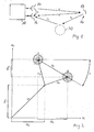
- Fig. 2 shows a pointer image of the signal components at the receiving antenna of the reading device.
- the components of the carrier signal are combined as direct coupling to the receiving antenna and the components formed by reflections of the carrier signal to objects components U K , which consist in the complex pointer image of an in-phase component U KI and a quadrature component U KQ . These components are not modulated by the detector wafer.
- the carrier signal is modulated with a modulation signal which changes in the embodiment between two modulation states A and B and is represented by a pointer U A for the modulation state A and a pointer U B for the modulation state B.
- the modulated component formed by the detection signal is as a component U T , consisting in the complex pointer image of an in-phase component U TI and a quadrature component U TQ . Disturbance components of the transmission path influence the position of the modulation states A and B in the complex pointer image, which is represented by circular regions with several scattering values.
- the evaluation circuit comprises a first I / Q demodulator 22, comprising a first multiplier 24, a second multiplier 26 and a local oscillator 28.
- the first multiplier 24 and the second multiplier 26 receive on the one hand an input signal U RF and on the other hand an oscillator signal of the local oscillator 28 with the same frequency as the carrier frequency of the input signal U RF .
- the oscillator signal is supplied to the first multiplier 24 as U LO * cos ( ⁇ t) and the second multiplier 26 phase shifted by 90 ° as U LO * sin ( ⁇ t).
- the signal path is divided into an in-phase channel I and a quadrature-phase channel Q.
- a signal processor 30 for the in-phase channel I and a signal processor 32 for the quadrature phase channel Q This is followed by a signal processor 30 for the in-phase channel I and a signal processor 32 for the quadrature phase channel Q.
- Outputs of the signal processor 30 for the in-phase channel I and the signal processor 32 for the quadrature phase channel Q lead to a computer 34, which carries out a trigonometric calculation of the phase position and the amplitude.
- Signal processors 30 and 32 include n multipliers 36, 36 ', 36 “; 38, 38', 38” and summers 40, 40 ', 40 “; 42, 42 ', 42 “for multiplying and summing the multiplication results of the signals of the in-phase channel I and the quadrature phase channel Q with evaluation functions f 1 (t), f 2 (t), f n (t), a common amplitude evaluator 44 and one summer each 48, 50 for averaging over several evaluation periods.
- the signals U I of the in-phase channel I and the signals U Q of the quadrature phase channel Q are supplied to the respective multipliers 36, 36 ', 36 ", 38, 38', 38" and with different evaluation functions f 1 (t), f 2 (FIG. t) f n (t) is multiplied.
- the evaluation functions each comprise an expected within a measurement period signal sequence of the detector and differ z., by the phase position of the expected burst.
- the multiplication is carried out separately for each sample within the measurement period (in case of digital signal processing For example, for each bit clock.) Subsequently, the multiplication products for each sample within the evaluation period are evaluated by the summers 40, 40 ', 40 "; 42, 42 ', 42 "summed.
- the maximum values are evaluated and selected by the following common amplitude evaluator 44 as amplitude values of the signal components A bI for the in-phase channel I and A bQ for the quadrature- phase channel Q.
- the following summers 48; 50 form averages of the amplitude values of the signal components over several evaluation periods, eg. B. over a complete data telegram of Detektierplättchens. By normalization, the absolute amplitudes of the signals for the in-phase channel I and for the quadrature-phase channel Q can also be determined.
- Both the averaged amplitudes A tI of the signals for the in-phase channel I and the averaged amplitudes A tQ of the signals for the quadrature phase channel Q are supplied to the subsequent computer 34.
- the computer 34 determines therefrom the phase position ⁇ t and the resulting amplitude A t
- U A I U A / 2 * cos ( ⁇ A ) + U K I / 2
- U B I U B / 2 * cos ( ⁇ B ) + U K I / 2
- U A Q U A / 2 * sin ( ⁇ A ) + U K Q / 2
- U B Q U B / 2 * sin ( ⁇ A ) + U K Q / 2 ,
Abstract
Description
Die Erfindung betrifft ein Verfahren zur Lokalisierung eines Detektierplättchens nach dem Oberbegriff des Anspruchs 1.The invention relates to a method for locating a detector wafer according to the preamble of
Zur Identifikation von Gütern bei der Lagerhaltung und beim Transport werden zunehmend Detektierplättchen eingesetzt, die jeweils mit den Gütern verbunden sind und eindeutige Identifikationsinformationen speichern. Durch Lesen der Identifikationsinformationen mittels eines Lesegerätes können so die Güter identifiziert werden.For identification of goods in warehousing and transport increasingly Detektierplättchen are used, which are each connected to the goods and store unique identification information. By reading the identification information by means of a reader so the goods can be identified.
Sind mehrere Güter in einer räumlich ausgedehnten Transport- oder Lagereinheit enthalten, sind zur Identifizierung Detektierplättchen und Lesegeräte mit einem ausreichend großen Erfassungsbereich erforderlich. Ferner ist auch die Anwendung eines Vereinzelungsverfahrens notwendig. Detektierplättchen und Lesgeräte, die auf Frequenzen im UHF-Bereich und darüber arbeiten, erfüllen die Voraussetzungen dafür. In diesem Frequenzbereich ist sowohl die notwendige hohe Reichweite als auch die notwendige hohe Datenübertragungsrate realisierbar, um alle im gewünschten Erfassungsbereich gleichzeitig befindlichen Detektierplättchen in ausreichend kurzer Zeit vereinzeln und getrennt lesen zu können.If several goods are contained in a spatially extended transport or storage unit, detection tiles and readers with a sufficiently large detection area are required for identification. Furthermore, the application of a separation process is necessary. Detector pads and readers that operate on UHF frequencies and above meet the requirements. In this frequency range Both the necessary high range and the necessary high data transmission rate can be realized in order to be able to isolate and simultaneously read all the detection plates simultaneously in the desired detection range in a sufficiently short time.
Da die Feldausbreitung im UHF-Bereich durch Reflexion und Absorption inhomogen sein kann, muss die Sendeleistung und Empfangsempfindlichkeit des Lesegerätes allerdings so groß sein, dass Detektierplättchen auch unter ungünstigen Konstellationen im angestrebten Erfassungsbereich sicher gelesen werden können. Dadurch ergibt sich das Problem, dass das Lesefeld bei mehreren benachbarten Transport- oder Lagereinheiten nicht gezielt auf eine ausgewählte Transport- oder Lagereinheiten beschränkt werden kann, sondern auch angrenzende Transport- oder Lagereinheiten erfasst. Um somit Güter einer ausgewählten Transport- oder Lagereinheit von Gütern anderer Transport- oder Lagereinheiten unterscheiden zu können, müssen deshalb die mit den Gütern verbundenen Detektierplättchen nach dem Lesen zusätzlich lokalisiert und anschließend selektiert werden.Since the field propagation in the UHF range can be inhomogeneous due to reflection and absorption, however, the transmitting power and receiving sensitivity of the reading device must be so great that detection plates can be safely read even under unfavorable constellations in the desired detection range. This results in the problem that the reading field can not be selectively limited to a selected transport or storage units in several adjacent transport or storage units, but also detects adjacent transport or storage units. In order to be able to distinguish goods of a selected transport or storage unit from goods of other transport or storage units, therefore, the detection plates connected to the goods must additionally be located after reading and then selected.
Der Erfindung liegt die Aufgabe zugrunde, ein Verfahren zur Lokalisierung eines Detektierplättchens zu schaffen, welches die Erfassung wenigstens einer Ortskoordinate ermöglicht.The invention has for its object to provide a method for locating a Detektierplättchens, which allows the detection of at least one location coordinate.
Diese Aufgabe wird bei einem Verfahren nach dem Oberbegriff des Anspruchs 1 durch die Merkmale dieses Anspruchs gelöst.This object is achieved in a method according to the preamble of
Weiterbildungen und vorteilhafte Ausgestaltungen ergeben sich aus den Unteransprüchen.Further developments and advantageous embodiments will become apparent from the dependent claims.
Die Erfindung geht von einem Detektierplättchen aus, das ein Detektiersignal abstrahlt, das von einem Lesegerät empfangen und ausgewertet wird. Dies kann ein passives Detektierplättchen sein, das das Trägersignal des Lesegerätes in Takte der Modulation in Amplitude und/oder Phase verändert oder ein aktives Detektierplättchen, dessen Detektiersignal einen Träger umfasst, der synchron zum Trägersignal des Lesegerätes generiert wird.The invention is based on a detection wafer which emits a detection signal which is received and evaluated by a reading device. This can be a passive detector wafer which changes the carrier signal of the reading device in terms of amplitude and / or phase modulation or an active detection wafer whose detection signal comprises a carrier which is generated synchronously with the carrier signal of the reading device.
Aufgrund der endlichen Ausbreitungsgeschwindigkeit elektromagnetischer Wellen verändern sich laufzeitabhängige Merkmale des Detektiersignals auf dem Weg vom Detektierplättchen zum Lesegerät. Die Änderung der Laufzeit ist dabei proportional zum Abstand zwischen dem Detektierplättchen und dem Lesegerät. Durch Auswertung des laufzeitabhängigen Merkmals des vom Lesegerät empfangenen Detektiersignals in Verbindung mit der bekannten Ausbreitungsgeschwindigkeit elektromagnetischer Wellen kann der Abstand bestimmt werden.Due to the finite propagation velocity of electromagnetic waves, runtime-dependent characteristics of the detection signal change on the way from the detection wafer to the reading device. The change of the running time is proportional to the distance between the detector plate and the reader. By evaluating the runtime-dependent feature of the detection signal received by the reading device in conjunction with the known propagation velocity of electromagnetic waves, the distance can be determined.
Vorzugsweise wird als laufzeitabhängiges Merkmal des empfangenen Detektiersignals die Phase und Amplitude des Detektiersignals ausgewertet.Preferably, the phase and amplitude of the detection signal is evaluated as a delay-dependent feature of the received detection signal.
Die Auswertung des laufzeitabhängigen Merkmals kann in diesem Fall nach der ohnehin für die Datengewinnung erforderlichen Demodulation und damit in einem niedrigeren Frequenzbereich im Vergleich zur Frequenz des Trägersignals erfolgen.The evaluation of the delay-dependent feature can be done in this case after the demodulation required anyway for the data acquisition and thus in a lower frequency range compared to the frequency of the carrier signal.
Bei einer ersten Ausführungsform des Verfahrens empfängt wenigstens während einer Lokalisierungszeitspanne das Detektierplättchen vom Lesegerät ein Trägersignal und strahlt ein mit einem Modulationssignal moduliertes Detektiersignal ab, das die gleiche Frequenz wie das Trägersignal besitzt. Das Modulationssignal weist Signalpunkte auf, die in einem Signalraumdiagramm durch eine Gerade approximierbar sind. Das vom Lesegerät empfangene Detektiersignal wird demoduliert, die Differenz der Phasenlage des Detektiersignals bei einem aktuellen Abstand und einem Referenzabstand zwischen Detektierplättchen und Lesegerät wird bestimmt und aus der Differenz der Phasenlage, der Trägerfrequenz und der Ausbreitungsgeschwindigkeit der elektromagnetischen Wellen wird der aktuelle Abstand zwischen dem Detektierplättchen und dem Lesegerät bestimmt.In a first embodiment of the method, at least during a localization period, the detection pad receives a carrier signal from the reader and emits a detection signal modulated with a modulation signal having the same frequency as the carrier signal. The modulation signal has signal points which can be approximated by a straight line in a signal space diagram. The detection signal received by the reader is demodulated, the difference of the phase position of the detection signal at a current distance and a reference distance between detector plate and reader is determined and from the difference of the phase position, the carrier frequency and the propagation velocity of the electromagnetic waves, the actual distance between the Detektierplättchen and the reader is determined.
Durch diese Vorschrift, dass das Modulationssignal Signalpunkte aufweist, die in einem Signalraumdiagramm durch eine Gerade approximierbar sind, wird erreicht, dass die Phasenlage des Detektiersignals reproduzierbar ist. Der Übergang zwischen den Signalpunkten muss nicht durch eine Gerade approximierbar sein. Außerhalb der Lokalisierungszeitspanne sind auch andere Modulationsarten anwendbar, bei denen die Signalpunkte in einem Signalraumdiagramm beliebig liegen können.By this rule, that the modulation signal has signal points that can be approximated by a straight line in a signal space diagram, it is achieved that the phase position of the detection signal is reproducible. The transition between the signal points does not have to be approximated by a straight line. Outside the localization time span, other modulation types are also applicable in which the signal points in a signal space diagram can be arbitrary.
Durch die endliche Ausbreitungsgeschwindigkeit elektromagnetischer Wellen ergibt sich ein Zeitunterschied zwischen Aussendung des Detektiersignals und Empfang beim Lesegerät, der zu einer Differenz zwischen der Phasenlage des vom Lesegerät erzeugten Trägersignals und der Phaselage des vom Lesegerät empfangenen Detektiersignals gleicher Frequenz führt. Diese Differenz der Phasenlagen ist ein Maß für den Abstand zwischen dem Detektierplättchen und dem Lesegerät.The finite speed of propagation of electromagnetic waves results in a time difference between transmission of the detection signal and reception at the reading device, which leads to a difference between the phase position of the carrier signal generated by the reading device and the phase position of the detection signal of the same frequency received by the reading device. These Difference of the phase positions is a measure of the distance between the detector plate and the reader.
Da die Differenz der Phasenlagen außerdem von der Frequenz des Trägersignals abhängt, ergibt sich bei den kurzen Wellenlängen im UHF-Bereich ein ausreichend großer Wert für die Differenz der Phasenlagen, um eine Abstandmessung mit einer Auflösung im cm-Bereich technisch realisieren zu können. Signallaufzeiten innerhalb des Lesegerätes und Detektierplättchens können als konstant betrachtet werden und beeinflussen die Differenz von Phasenlagenänderungen bei Abstandsänderungen nicht.Since the difference in the phase positions also depends on the frequency of the carrier signal, the short wavelengths in the UHF range result in a sufficiently large value for the difference of the phase positions in order to technically realize a distance measurement with a resolution in the cm range. Signal propagation times within the reader and detector wafer can be considered constant and do not affect the difference in phase position changes with distance changes.
Zur mathematischen Beschreibung der Signale werden folgende Abkürzungen verwendet:
- a
- Abstand zwischen Detektierplättchen und Lesegerät
- f
- Trägerfrequenz des Lesegerätes
- c
- Ausbreitungsgeschwindigkeit der Wellen in Luft
- t
- Laufzeit des Signals vom Lesegerät zum Detektierplättchen und zurück
- λ
- Wellenlänge der Trägerfrequenz; λ = c/f
- T
- Periodenbauer bei f; T = 1/f
- n
- Kreiszahl
- α
- Phasenlage; α = 2π*t/T
- N
- 0, 1, 2... Mehrdeutigkeit der Phasenlage
- a
- Distance between detector plate and reader
- f
- Carrier frequency of the reader
- c
- Propagation speed of the waves in air
- t
- Runtime of the signal from the reader to the detector plate and back
- λ
- Wavelength of the carrier frequency; λ = c / f
- T
- Period builder at f; T = 1 / f
- n
- Kreiszahl
- α
- Phase position; α = 2π * t / T
- N
- 0, 1, 2 ... ambiguity of the phase position
Für die Laufzeit ergibt sich t = 2*a/c und nach Umstellung für den Abstand a = t*c/2. Unter Einbeziehung der Phasenlage folgt für die Laufzeit t = (α/2π + N) * T und nach Umstellung für den Abstand a = (α/2π + N) * T * c/2 oder a = (α/2π + N) * 1/f * c/2 oder a = α * c/4nf für N = 0.For the running time t = 2 * a / c and after conversion for the distance a = t * c / 2. Taking into account the phase angle, the transit time is t = (α / 2π + N) * T and after conversion for the distance a = (α / 2π + N) * T * c / 2 or a = (α / 2π + N) * 1 / f * c / 2 or a = α * c / 4nf for N = 0.
Bei der Trägerfrequenz f nimmt die Phasenlage nach einer Strecke λ/2 wieder denselben Wert an. Die Strecke λ/2 ergibt sich daraus, dass die Laufzeit t des Signals sowohl den Weg vom Lesegerät zum Detektierplättchen hin als auch den Weg vom Detektierplättchen zum Lesegerät zurück umfasst. Innerhalb einer Strecke < λ/2 ist die Differenz der Phasenlagen zwischen einem aktuellen Abstand und einem Referenzabstand eindeutig. Bei eine Strecke > λ/2 treten Mehrdeutigkeiten N auf, die durch stetige Aktualisierung des Aufenthaltsortes des Detektierplättchens in Schritten < λ/2 aufgelöst werden können.At the carrier frequency f, the phase angle assumes the same value again after a distance λ / 2. The distance λ / 2 results from the fact that the transit time t of the signal comprises both the path from the reading device to the detection plate and the path from the detection plate back to the reading device. Within a distance <λ / 2 the difference of the phase positions between a current distance and a reference distance is unique. For a distance> λ / 2, ambiguities N occur, which can be resolved by continuously updating the location of the detector wafer in steps <λ / 2.
Eine andere Möglichkeit, Mehrdeutigkeiten bei Strecken > λ/2 zu beseitigen, besteht bei einer zweiten Ausführungsform des Verfahrens. Wenigstens während einer Lokalisierungszeitspanne empfängt das Detektierplättchen vom Lesegerät Trägersignale einer ersten und anschließend wenigstens einer zweiten Frequenz und strahlt mit jeweils einem Modulationssignal modulierte Detektiersignale ab, die jeweils die gleiche Frequenz wie die Trägersignale besitzen. Die Modulationssignale weisen Signalpunkte auf, die in einem Signalraumdiagramm durch eine Gerade approximierbar sind. Die vom Lesegerät empfangenen Detektiersignale werden demoduliert, die jeweilige Phasenlage des jeweiligen Detektiersignals wird bestimmt und durch gemeinsame Auswertung wird aus den Phasenlagen, den Trägerfrequenzen und der Ausbreitungsgeschwindigkeit der elektromagnetischen Wellen der aktuelle Abstand zwischen dem Detektierplättchen und dem Lesegerät bestimmt.Another possibility for eliminating ambiguities in distances> λ / 2 consists in a second embodiment of the method. At least during a localization period, the detection pad receives from the reader carrier signals of a first and then at least a second frequency and emits, each with a modulation signal modulated detection signals, each having the same frequency as the carrier signals. The modulation signals have signal points that can be approximated by a straight line in a signal space diagram. The detection signals received by the reading device are demodulated, the respective phase position of the respective detection signal is determined, and by common evaluation, the actual distance between the detection plate and the reading device is determined from the phase positions, the carrier frequencies and the propagation velocity of the electromagnetic waves.
Alternativ kann das Detektierplättchen vom Lesegerät Trägersignale einer ersten und gleichzeitig wenigstens einer zweiten Frequenz empfangen und gleichzeitig mit jeweils einem Modulationssignal modulierte Detektiersignale abstrahlen. Die vom Lesegerät empfangenen Detektiersignale werden durch Filter getrennt und demoduliert, die jeweilige Phasenlage des jeweiligen Detektiersignals wird gleichzeitig bestimmt.Alternatively, the detector wafer can receive carrier signals of a first and at the same time at least one second frequency from the reader and at the same time emit detection signals modulated with a respective modulation signal. The detection signals received by the reader are filtered separated and demodulated, the respective phase position of the respective detection signal is determined simultaneously.
Durch eine gleichzeitige Abstrahlung der Detektiersignale auf unterschiedlichen Frequenzen gegenüber einer zeitversetzten Abstrahlung werden zeitveränderliche Einflüsse des Lesefeldes und des Abstandes auf das Auswertungsergebnis vermieden.By a simultaneous radiation of the detection signals at different frequencies over a time-shifted radiation time-variable influences of the reading field and the distance are avoided to the evaluation result.
Bei unterschiedlichen Frequenzen treten bei gleichen Abstanden andere Phasenlagen auf. Da die Phasenlagen bei diesen unterschiedlichen Frequenzen proportional zum Abstand sind, ist auch die Differenz der Phasenlagen proportional zum Abstand. Daher ergibt sich der Abstand nicht nur für die absolute Phasenlage bei einer Frequenz, sondern auch für die Differenz der Phasenlagen bei der Differenz unterschiedlicher Frequenzen.At different frequencies occur at the same distances on other phases. Since the phase angles at these different frequencies are proportional to the distance, the difference of the phase positions is proportional to the distance. Therefore, the distance does not only result for the absolute phase position at one frequency, but also for the difference of the phase positions at the difference of different frequencies.
Ein Referenzabstand ist dann nicht erforderlich. Störquellen durch nicht langzeitkonstante Effekte fallen durch die Differenzbildung heraus. Es ist aber eine höhere Präzision bei Bestimmung der Phasenlagen nötig.A reference distance is then not required. Sources of interference due to non-long-term effects are eliminated by the difference formation. But it is a higher precision in determining the phase angles necessary.
Zur weiteren mathematischen Beschreibung der Signale werden folgende Abkürzungen verwendet:
- f1, f2,
- Trägerfrequenzen des Lesegerätes
- λ1, λ1
- Wellenlänge der Trägerfrequenz; λ1,2 = c/f1,2
- α1, α2
- Phasenlagen; α1,2 = 2π*t/T1,2
- f 1 , f 2 ,
- Carrier frequencies of the reader
- λ 1 , λ 1
- Wavelength of the carrier frequency; λ 1,2 = c / f 1,2
- α 1 , α 2
- Phase angles; α 1,2 = 2π * t / T 1,2
Die Formel für den Abstand bei zwei unterschiedlichen Phasenlagen und Trägerfrequenzen lautet dann: ![]()
![]()
Erst bei Strecken |λ2 - λ1| ≥ min(λ1,2) entstehen wiederum Mehrdeutigkeiten.Only at distances | λ 2 - λ 1 | ≥ min (λ 1,2 ) again results in ambiguities.
Durch entsprechende Auswahl der Trägerfrequenzen kann im UHF-Bereich ein Abstandsbereich innerhalb der durch die übliche geringe Sendeleistung des Lesegerätes begrenzten Reichweite des Lesefeldes ohne Mehrdeutigkeiten erfasst werden. Bei Lesegeräten mit größerer Lesereichweite oder bei höheren Trägerfrequenzen kann die Phasenlage auch bei mehr als zwei Trägerfrequenzen gemessen werden, um diese Mehrdeutigkeiten aufzulösen.By appropriate selection of the carrier frequencies, a distance range within the range of the reading field limited by the usual low transmission power of the reading device can be detected without ambiguity in the UHF range. For readers with a longer read range or at higher carrier frequencies, the phase angle can also be measured at more than two carrier frequencies in order to resolve these ambiguities.
Gemäß einer Weiterbildung kann während der Lokalisierungszeitspanne die Phasenlage wenigstens zweimal mit zeitlichem Abstand bestimmt werden und eine Änderung der Phasenlage im zeitlichem Abstand als Relativbewegung zwischen Lesegerät und Detektierplättchen ermittelt werden, während eine Übereinstimmung als konstanter Abstand zwischen Lesegerät und Detektierplättchen ermittelt wird.According to a development, the phase position can be determined at least twice with a time interval during the localization period and a change in the phase position at a time interval can be determined as a relative movement between the reader and detector wafer, while a match is determined as a constant distance between the reader and detector wafer.
Durch zeitlich versetzte Abstandmessungen wird ein Kriterium ermittelt, ob sich Lesegerät und Detektierplättchen im Abstand relativ zueinander bewegen oder nicht. Eine Nutzungsmöglichkeit dieser Kriterium besteht darin, mit Detektierplättchen versehene Güter auf einer bewegten Transporteinheit, z. B. einer Palette auf einem Gabelstapler von stationären mit Detektierplättchen versehene Gütern, z. B. auf Paletten in einem Regal voneinander zu unterscheiden.By time-offset distance measurements, a criterion is determined as to whether the reader and the detector plate move relative to each other at a distance or not. One possibility for using this criterion is to provide goods provided with detector platelets on a moving transport unit, e.g. As a pallet on a forklift from stationary provided with Detektierplättchen goods, z. B. on pallets on a shelf from each other.
Darüber hinaus kann aus dem Maß der Änderung des Abstandes oder der Phasenlage innerhalb eines Zeitintervalls die Geschwindigkeit und/oder der Richtungsvektor der Bewegung ermittelt werden.In addition, the speed and / or the direction vector of the movement can be determined from the extent of the change in the distance or the phase position within a time interval.
Bei einer technischen Ausführung des Verfahrens wird das Detektiersignal während der Lokalisierungszeitspanne mit einem Signal moduliert, welches zwischen wenigstens zwei Zuständen, z. B. A und B, wechselt. Das vom Lesegerät empfangene Detektiersignal wird in einem Demodulator durch Multiplikation mit einem zur Trägerfrequenz synchronen Signal in eine Inphase- und eine Quadraturkomponente zerlegt. Aus der Differenz der Signalanteile der wenigstens zwei Zustände für die Inphasekomponente wird die Inphasekomponente des Modulationssignals gewonnen und aus der Differenz der Signalanteile der wenigstens zwei Zustände für die Quadraturkomponente wird die Quadraturkomponente des Modulationssignals gewonnen. Die Phasenlage wird dann trigonometrisch bestimmt.In an industrial embodiment of the method, the detection signal during the localization period is modulated with a signal which is between at least two states, for. B. A and B, changes. The detection signal received by the reading device is decomposed in a demodulator by multiplication with a signal synchronous to the carrier frequency into an in-phase component and a quadrature component. From the difference of the signal components of the at least two states for the in-phase component, the in-phase component of the modulation signal is obtained and from the difference of the signal components of the at least two states for the quadrature component, the quadrature component of the modulation signal is obtained. The phase position is then determined trigonometrically.
Zur mathematischen Beschreibung der Signale werden folgende Abkürzungen verwendet:
- X(t)
- der Amplitudenverlauf des unmodulierten Trägersignals
- UIN-A
- Empfangssignal im Modulatorzustand A
- UIN-B
- Empfangssignal im Modulatorzustand B
- UA
- vom Detektierplättchen beeinflusster Signalanteil A
- UB
- vom Detektierplättchen beeinflusster Signalanteil B
- UKI
- vom unmodulierten Trägersignal beeinflusster Signalanteil der Inphasekomponente
- UKQ
- vom unmodulierten Trägersignal beeinflusster Signalanteil der Quadraturkomponente
- UAI
- vom Detektierplättchen beeinflusster Signalanteil A der Inphasekomponente
- UAQ
- vom Detektierplättchen beeinflusster Signalanteil A der Quadraturkomponente
- UBI
- vom Detektierplättchen beeinflusster Signalanteil B der Inphasekomponente
- UBQ
- vom Detektierplättchen beeinflusster Signalanteil B der Quadraturkomponente
- UI
- Inphasekomponente des Modulationssignals
- UQ
- Quadraturkomponente des Modulationssignals
- ϕ
- Phase allgemein
- ϕA
- Phase des vom Detektierplättchen beeinflussten Signalanteils A
- ϕB
- Phase des vom Detektierplättchen beeinflussten Signalanteils B
- X (t)
- the amplitude profile of the unmodulated carrier signal
- U IN-A
- Received signal in modulator state A
- U IN-B
- Received signal in modulator state B
- U A
- signal component A influenced by the detector plate
- U B
- signal component B influenced by the detector plate
- U KI
- from the unmodulated carrier signal influenced signal component of the in-phase component
- U KQ
- from the unmodulated carrier signal influenced signal component of the quadrature component
- U AI
- Signal component A of the in-phase component influenced by the detector plate
- U AQ
- from the Detektierplättchen influenced signal component A of the quadrature component
- U BI
- signal component B influenced by the detector wafer B of the in-phase component
- U BQ
- from the Detektierplättchen affected signal component B of the quadrature component
- U I
- Inphase component of the modulation signal
- U Q
- Quadrature component of the modulation signal
- φ
- Phase general
- φ A
- Phase of the signal affected by the Detektplättchen signal component A.
- φ B
- Phase of the signal affected by the Detektplättchen B signal component
Vom Lesegerät wird ein unmoduliertes Trägersignals der Form X(t) = cos(2nft) = cos(x(t)) erzeugt und zum Detektierplättchen übertragen. Ein Modulator des Detektierplättchens moduliert das Trägersignal mit einem Modulationssignal, das zwischen den wenigstens zwei Zuständen A und B wechselt. Das Lesegerät empfängt neben dem Trägersignal durch direkte Einkopplung und Reflexion einen Teil des modulierten Detektiersignals. Das Empfangssignal im Modulatorzustand A ist: ![]()
Das Empfangssignal im Modulatorzustand B ist: ![]()
![]()
The received signal in modulator state B is: ![]()
In einem I/Q-Demodulator wird das Eingangssignals mit einem Referenzsignal und einem um 90° phasenverschobenen Referenzsignal multipliziert. Das Ergebnis der Multiplikation lautet in der allgemeinen normierten Form für die I-Komponente: ![]()
und für die Q-Komponente: ![]()
![]()
and for the Q component: ![]()
Hierbei steht der Ausdruck sin(x+ϕ) für das Empfangssignal und die Ausdrücke sin(x) bzw. cos(x) repräsentieren das Referenzsignal bzw. sein phasenverschobenes Äquivalent. Das 2x im letzten Term steht für Signalanteile der doppelten Trägerfrequenz, die anschließend durch Tiefpassfilter unterdrückt werden.Here, the expression sin (x + φ) stands for the received signal and the expressions sin (x) and cos (x) represent the reference signal or its phase-shifted equivalent. The 2x in the last term stands for signal components of twice the carrier frequency, which are then suppressed by low-pass filters.
![]()
ergibt sich durch die Multiplikation dann für den I-Kanal: 
und für den Q-Kanal: 
![]()
results from the multiplication then for the I-channel:
and for the Q-channel:
![]()
ergibt sich durch die Multiplikation dann für den I-Kanal: 
![]()
und für den Q-Kanal: 
![]()
results from the multiplication then for the I-channel: ![]()
and for the Q-channel:
Durch Abtrennen der hochfrequenten Anteile bleiben übrig für den I-Kanal: ![]()
![]()
und für den Q-Kanal: ![]()
![]()
![]()
![]()
and for the Q-channel: ![]()
![]()
Durch Differenzbildung wird der vom unmodulierten Trägersignal beeinflusste Signalanteil UKI bzw. UKQ entfernt und es verbleiben die Inphasekomponente des Modulationssignals UI und die Quadraturkomponente des Modulationssignals UQ als einzige Größen, die nach einer Tiefpassfilterung gemessen werden. ![]()
![]()
![]()
![]()
Die Phasenlage des aktuellen Abstandes bezogen auf eine Referenzphasenlage eines Referenzabstandes ergibt sich dann als α = arctan (UQ/UI) .The phase angle of the actual distance relative to a reference phase position of a reference distance then results as α = arctan (U Q / U I ).
In die Phasenlage α gehen Phasenverschiebungen durch Laufzeiten bei der Signalverarbeitung innerhalb des Lesegerätes und des Detektierplättchens ein. Diese Phasenverschiebungen werden aber durch Bezug auf eine Referenzphase bei einem Referenzabstand kompensiert.Phase shifts α are caused by phase shifts due to propagation delays in signal processing within the reader and the detector wafer. However, these phase shifts are compensated by reference to a reference phase at a reference distance.
Unter der Voraussetzung, dass die Modulationszustände A und B zugeordnet werden können, ist a = α * c/4nf für eine Strecke < λ/2. Können die Zustände A und B zwar unterschieden, aber nicht zugeordnet werden, ist nur ein Winkelbereich für α von 0° bis 180° eindeutig. Mehrdeutigkeiten treten dann bereits im Abstand von λ/4 auf.Assuming that the modulation states A and B can be assigned, a = α * c / 4nf for a distance <λ / 2. Although the states A and B can be distinguished but not assigned, only an angle range for α from 0 ° to 180 ° is unambiguous. Ambiguities then occur at a distance of λ / 4.
Ferner kann aus den Inphase- und Qadraturkomponenten der einzelnen Messwerte durch U2 = UI 2 + UQ 2 ein resultierender Amplitudenwert des Detektiersignals bestimmt werden.Furthermore, a resulting amplitude value of the detection signal can be determined from the in-phase and quadrature components of the individual measured values by U 2 = U I 2 + U Q 2 .
Dadurch können die ermittelten Abstandwerte ergänzend verifiziert werden. Außerdem ist durch Auswertung der Amplitude des Detektiersignals bei bekanntem Abstand eine vergleichende Qualitätsprüfung von Detektierplättchen bei Produktion und Einsatz möglich. Eine Auswertung der Amplituden kann über einen großen Frequenzbereich durchgeführt werden, um z. B. Resonanzfrequenz und Güte auszumessen.As a result, the determined distance values can be additionally verified. In addition, by evaluating the amplitude of the detection signal at a known distance, a comparative quality inspection of detector plates during production and use is possible. An evaluation of the amplitudes can be carried out over a wide frequency range, z. B. measure resonance frequency and quality.
Um eine Zuordnung zu den wenigstens zwei Modulationszuständen A und B herzustellen, können gemäß einer Weiterbildung die die Signalanteile der wenigstens zwei Zustände über wenigstens einen Bewertungszeitraum mit wenigstens zwei eine erwartete Signalfolge umfassenden Bewertungsfunktionen bewertet werden. Ein eine maximale Amplitude lieferndes Bewertungsergebnis wird als Amplitude der Signalanteile der wenigstens zwei Zustände ausgewertet.In order to establish an association with the at least two modulation states A and B, according to a development, the signal components of the at least two states can be evaluated over at least one evaluation period with at least two evaluation functions comprising an expected signal sequence. An evaluation result yielding a maximum amplitude is evaluated as the amplitude of the signal components of the at least two states.
Entspricht die empfangene Signalfolge der erwarteten Signalfolge und wird die empfangene Signalfolge phasensynchron mit der die erwartete Signalfolge umfassenden Bewertungsfunktionen z. B. durch Multiplikation bewertet so liefert das Bewertungsergebnis einen maximalen positiven Wert, der einem Amplitudenwert entspricht. Anderenfalls liefert das Bewertungsergebnis einen im Vergleich zum maximalen positiven Wert kleineren positiven oder auch negativen Wert. Bei Bewertung mit zwei oder mehreren Bewertungsfunktionen ergeben sich somit unterschiedliche Bewertungsergebnisse. Beim Bewertungsergebnis mit der maximalen Amplitude ist die Wahrscheinlichkeit am größten, das die wenigstens zwei Zustände A und B richtig zugeordnet sind.If the received signal sequence corresponds to the expected signal sequence and the received signal sequence is phase-synchronized with the evaluation function comprising the expected signal sequence z. B. evaluated by multiplication so the evaluation result delivers a maximum positive value, the amplitude value equivalent. Otherwise, the evaluation result provides a smaller positive or negative value than the maximum positive value. When evaluating with two or more valuation functions, different valuation results result. In the evaluation result with the maximum amplitude, the probability that the at least two states A and B are correctly assigned is greatest.
Ein Spezialfall liegt vor, wenn lediglich zwei Bewertungsfunktionen genutzt werden, die sich nur um einen konstanten Faktor unterscheiden. Eine Bewertung mit der zweiten Bewertungsfunktion entspricht dann einer Multiplikation des Bewertungsergebnisses der ersten Bewertungsfunktion mit diesem Faktor.A special case exists when only two evaluation functions are used, which differ only by a constant factor. An evaluation with the second evaluation function then corresponds to a multiplication of the evaluation result of the first evaluation function by this factor.
Die Amplituden der Signalanteile der wenigstens zwei Zustände können über mehrere Bewertungszeiträume gemittelt werden.The amplitudes of the signal components of the at least two states can be averaged over several evaluation periods.
Durch die Mittelwertbildung werden Störanteile reduziert und so die Messgenauigkeit verbessert.Averaging reduces noise components and thus improves measurement accuracy.
In der Nähe der zu identifizierenden Detektierplättchen kann ein Referenzdetektierplättchen in einem Referenzabstand zum Lesegerät angeordnet werden. Durch Vergleich der gemessenen Phasenlage mit einer Sollphasenlage für den Referenzabstand kann ein Korrekturwert ermittelt werden und die gemessene Phasenlage der identifizierenden Detektierplättchen mit dem Korrekturwert korrigiert werden.In the vicinity of the detection plates to be identified, a reference detection plate can be arranged at a reference distance to the reading device. By comparing the measured phase position with a desired phase position for the reference distance, a correction value can be determined and the measured phase position of the identifying detector plates can be corrected with the correction value.
Auf diese Weise lassen sich Einflüsse auf die Phasenlage, wie sie z. B. durch Reflexionen des Trägersignals und/oder des Detektiersignals an Gegenständen hervorgerufen werden, kompensieren.In this way, influences on the phase position, as z. B. caused by reflections of the carrier signal and / or the detection signal to objects compensate.
Das Referenzdetektiersignal des Referenzdetektierplättchen kann mit einem vom Modulationssignal des zu identifizierenden Detektierplättchens abweichenden Modulationssignal moduliert werden und im Lesegerät das Referenzdetektiersignal des Referenzdetektierplättchen und das Detektiersignal des zu identifizierenden Detektierplättchens durch Filter getrennt und gleichzeitig ausgewertet werden.The reference detection signal of the reference detection plate can be modulated with a modulation signal deviating from the modulation signal of the detection plate to be identified, and in the reading device the reference detection signal of the reference detection plate and the detection signal of the detection plate to be identified are separated by filters and simultaneously evaluated.
Durch eine gleichzeitige Auswertung des Referenzdetektiersignals des Referenzdetektierplättchen und des Detektiersignals des zu identifizierenden Detektierplättchens gegenüber einer zeitversetzten Auswertung werden zeitveränderliche Einflüsse des Lesefeldes auf das Auswertungsergebnis vermieden.By a simultaneous evaluation of the reference detection signal of the reference detection plate and the detection signal of the detection wafer to be identified compared to a time-shifted evaluation, time-variable influences of the reading field on the evaluation result are avoided.
Gemäß einer Weiterbildung können mehrere Abstandmessungen bei wenigstens zwei unterschiedlichen Antennenpositionen des Lesegerätes durchgeführt werden und aus den Schnittpunkten der durch Abstandmessungen ermittelten Abstandsortkurven der Antennenpositionen des Lesegerätes der Standort des Detektierplättchens bestimmt werden.According to a development, a plurality of distance measurements can be carried out in at least two different antenna positions of the reading device and the location of the detection plate can be determined from the intersections of the distance location curves of the antenna positions of the reading device determined by distance measurements.
Dabei können die unterschiedlichen Antennenpositionen durch Umschalten mehrerer örtlich getrennter Antennen des Lesegerätes angesteuert werden.In this case, the different antenna positions can be controlled by switching a plurality of locally separate antennas of the reader.
Durch die Abstandmessungen bei unterschiedlichen Antennenpositionen wird die Lokalisierung weiter verbessert, da zusätzlich zum Abstand auch die Richtung zwischen Lesegerät und Detektierplättchen bestimmt werden kann.By the distance measurements at different antenna positions, the localization is further improved, since in addition to the distance, the direction between the reader and Detektierplättchen can be determined.
Ergänzend kann nach Bestimmung des Standortes des Detektierplättchens die Strahlungskeule einer aus wenigstens zwei örtlich getrennter Antennen bestehenden Antennenanordnung durch phasenverschobene Ansteuerung der Antennen in Richtung des Detektierplättchens ausgerichtet wird.In addition, after determining the location of the detector wafer, the radiation lobe of an antenna arrangement consisting of at least two spatially separated antennas can pass through phase-shifted control of the antennas is aligned in the direction of the detector plate.
Durch Ausrichtung der Strahlungskeule wird die Lesefeldstärke und gleichzeitig der Störabstand gegenüber einer mögliche Störstrahlung aus anderen Richtungen erhöht. Dadurch wird die Lesequalität der Detektiersignale verbessert, was sich auch günstig auf die Genauigkeit der Abstands- und der ggf. zusätzlichen Richtungsmessung auswirkt.By aligning the radiation lobe, the reading field strength and at the same time the signal-to-noise ratio is increased compared to possible interference radiation from other directions. As a result, the reading quality of the detection signals is improved, which also has a favorable effect on the accuracy of the distance and possibly additional direction measurement.
Ferner kann das Detektierplättchen vor der Abstandmessung durch das Lesegerät aus wenigstens zwei unterschiedlichen Antennenpositionen aktiviert werden. Ergänzend oder alternativ kann das Detektierplättchen vor der Abstandmessung durch das Lesegerät auf wenigstens zwei unterschiedlichen Trägerfrequenzen aktiviert werden.Furthermore, the detection plate can be activated before the distance measurement by the reading device from at least two different antenna positions. Additionally or alternatively, the detector wafer can be activated on at least two different carrier frequencies before the distance measurement by the reader.
Im UHF-Bereich kann durch Abschattungen oder Stehwellen aufgrund von Reflexionen die Lesefeldstärke Minima aufweisen. Befindet sich ein Detektierplättchen zufällig am Ort eines solchen Minimums, besteht die Gefahr, dass das Detektierplättchen nicht identifiziert werden kann. Durch Nutzung unterschiedlicher Antennenpositionen und/oder Trägerfrequenzen wird die Verteilung der Lesefeldstärke verändert. Dadurch erhöht sich die Wahrscheinlichkeit, Detektierplättchen identifizieren zu können.In the UHF range, shading or standing waves due to reflections may cause the reading field intensity to be at a minimum. If a detector wafer happens to be at the location of such a minimum, there is a risk that the detector wafer can not be identified. By using different antenna positions and / or carrier frequencies the distribution of the reading field strength is changed. This increases the probability of being able to identify detector plates.
Nachfolgend wird die Erfindung anhand von Ausführungsbeispielen beschrieben, die in der Zeichnung dargestellt sind. Darin zeigen:
- Fig. 1
- eine Anordnung eines Lesegerätes und eines Detektierplättchens mit einer Darstellung von Signalkomponenten,
- Fig. 2
- ein Zeigerbild der Signalkomponenten am Eingang des Lesegerätes,
- Fig. 3
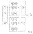
- ein Blockschaltbild einer Auswerteschaltung des Lesegerätes,
- Fig. 1
- an arrangement of a reading device and a detector plate with a representation of signal components,
- Fig. 2
- a pointer image of the signal components at the input of the reading device,
- Fig. 3
- a block diagram of an evaluation circuit of the reading device,
Fig. 1 zeigt eine Anordnung eines Lesegerätes 10 und eines Detektierplättchens 12 mit einer Darstellung von Signalkomponenten. Das Lesegerät 10 umfasst einen Sender, der über eine Sendeantenne 14 ein Trägersignal abstrahlt und einen Empfänger mit einer Empfangsantenne 16, einem Demodulator und einer Auswerteschaltung. Das Detektierplättchen 12 umfasst eine Detektierplättchenantenne 18, eine Steuerschaltung, einen Speicher und einen Modulator. Das Detektierplättchen 12 kann ein passiver, vom Lesegerät 10 mit Energie gespeistes Detektierplättchen oder ein Detektierplättchen mit eigener Energiequelle sein.1 shows an arrangement of a
Der Modulator des Detektierplättchens 12 moduliert das Trägersignal des Lesegerätes 10 durch Bedämpfung im Takte seines Modulationsinhalts. Dies stellt eine Nutzsignalkomponente dar, die als Detektiersignal mit der Laufzeit τt von der Detektierplättchenantenne 18 zur Empfangsantenne 16 des Lesegerätes gelangt 10.The modulator of the
Außerdem gelangen zur Empfangsantenne 16 des Lesegerätes 10 auch Komponenten des Trägersignals mit der Laufzeit τr selbst durch direkte Einkopplung von der Sendeantenne 14 sowie durch Reflexionen des Trägersignals mit der Laufzeit τd2 an Gegenständen 20. Zwar können auch Reflexionen des Detektiersignals mit der Laufzeit τd1 an Gegenständen 20 auftreten, diese werden nachfolgend aber nicht weiter berücksichtigt.In addition, the receiving
Fig. 2 zeigt ein Zeigerbild der Signalkomponenten an der Empfangsantenne des Lesegerätes. Dabei sind die Komponenten des Trägersignals als direkte Einkopplung auf die Empfangsantenne und die durch Reflexionen des Trägersignals an Gegenständen gebildeten Komponenten zur Komponente UK zusammengefasst, die im komplexen Zeigerbild aus einer Inphasekomponente UKI und einer Quadraturkomponente UKQ bestehen. Diese Komponenten sind nicht durch das Detektierplättchen moduliert.Fig. 2 shows a pointer image of the signal components at the receiving antenna of the reading device. In this case, the components of the carrier signal are combined as direct coupling to the receiving antenna and the components formed by reflections of the carrier signal to objects components U K , which consist in the complex pointer image of an in-phase component U KI and a quadrature component U KQ . These components are not modulated by the detector wafer.
Im Detektierplättchen wird das Trägersignal mit einem Modulationssignal moduliert, das im Ausführungsbeispiel zwischen zwei Modulationszuständen A und B wechselt und durch einen Zeiger UA für den Modulationszustand A und einen Zeiger UB für den Modulationszustand B dargestellt wird. Die durch das Detektiersignal gebildete modulierte Komponente ist als Komponente UT, bestehend im komplexen Zeigerbild aus einer Inphasekomponente UTI und einer Quadraturkomponente UTQ. Störanteile des Übertragungsweges beeinflussen die Lage der Modulationszustände A und B im komplexen Zeigerbild was durch kreisförmige Bereiche mit mehreren streuenden Werten dargestellt ist.In the detection wafer, the carrier signal is modulated with a modulation signal which changes in the embodiment between two modulation states A and B and is represented by a pointer U A for the modulation state A and a pointer U B for the modulation state B. The modulated component formed by the detection signal is as a component U T , consisting in the complex pointer image of an in-phase component U TI and a quadrature component U TQ . Disturbance components of the transmission path influence the position of the modulation states A and B in the complex pointer image, which is represented by circular regions with several scattering values.
Fig. 3 zeigt ein Blockschaltbild einer Auswerteschaltung des Lesegerätes. Die Auswerteschaltung umfasst einen ersten I/Q-Demodulator 22, bestehend aus einem ersten Multiplizierer 24, einem zweiten Multiplizierer 26 und einem Lokaloszillator 28. An den ersten Multiplizierer 24 und den zweiten Multiplizierer 26 gelangt einerseits ein Eingangssignal URF und andererseits ein Oszillatorsignals des Lokaloszillators 28 mit der gleichen Frequenz wie die Trägerfrequenz des Eingangssignals URF.3 shows a block diagram of an evaluation circuit of the reading device. The evaluation circuit comprises a first I /
Das Oszillatorsignal wird dem ersten Multiplizierer 24 als ULO * cos(ωt) und dem zweiten Multiplizierer 26 um 90° phasenverschoben als ULO * sin(ωt) zugeführt. Nach dem I/Q-Demodulator 22 ist der Signalweg in einen Inphasekanal I und einen Quadraturphasekanal Q unterteilt. Daran schließen sich ein Signalprozessor 30 für den Inphasekanal I und ein Signalprozessor 32 für den Quadraturphasekanal Q an. Ausgänge des Signalprozessors 30 für den Inphasekanal I und des Signalprozessor 32 für den Quadraturphasekanal Q führen zu einem Rechner 34, der eine trigonometrische Berechnung der Phasenlage und der Amplitude vornimmt.The oscillator signal is supplied to the
Die Signalprozessoren 30 und 32 umfassen n Multiplizierer 36, 36', 36"; 38, 38', 38" und Summierer 40, 40', 40''; 42, 42', 42" zur Multiplikation und Summierung der Multiplikationsergebnisse der Signale des Inphasekanals I und des Quadraturphasekanals Q mit Bewertungsfunktionen f1(t), f2(t), fn(t), einen gemeinsamen Amplitudenbewerter 44 und jeweils einen Summierer 48; 50 zur Mittelwertbildung über mehrere Bewertungszeiträume.
Im Signalprozessor 30; 32 werden die Signale UI des Inphasekanals I und die Signale UQ des Quadraturphasekanals Q den jeweiligen Multiplizierer 36, 36', 36" ; 38, 38', 38'' zugeführt und mit unterschiedlichen Bewertungsfunktionen f1(t), f2(t), fn(t) multipliziert. Die Bewertungsfunktionen umfassen jeweils eine innerhalb eines Bewertungszeitraums erwartete Signalfolge des Detektierplättchens und unterscheiden sich z. B. durch die Phasenlage der erwarteten Signalfolge. Die Multiplikation erfolgt gesondert für jeden Abtastwert innerhalb des Bewertungszeitraums (bei digitaler Signalverarbeitung z. B. für jeden Bit-Takt). Anschließend werden die Multiplikationsprodukte für jeden Abtastwert innerhalb des Bewertungszeitraums durch die Summierer 40, 40', 40"; 42, 42', 42" summiert.In the signal processor 30; 32, the signals U I of the in-phase channel I and the signals U Q of the quadrature phase channel Q are supplied to the
Je nach Übereinstimmung der Bewertungsfunktionen mit den vom Detektierplättchen stammenden Eingangssignalen ergeben sich unterschiedliche Werte für die summierten Multiplikationsprodukte der Abtastwerte. Die maximalen Werte werden durch den nachfolgenden gemeinsamen Amplitudenbewerter 44 als Amplitudenwerte der Signalanteile AbI für den Inphasekanals I und AbQ für den Quadraturphasekanals Q ausgewertet und selektiert. Die nachfolgen Summierer 48; 50 bilden Mittelwerte der Amplitudenwerte der Signalanteile über mehrere Bewertungszeiträume, z. B. über ein vollständiges Datentelegramm des Detektierplättchens. Durch Normierung können auch die absoluten Amplituden der Signale für den Inphasekanals I und für den Quadraturphasekanals Q ermittelt werden.Depending on the agreement of the evaluation functions with the input signals originating from the detection plate, different values result for the summed multiplication products of the samples. The maximum values are evaluated and selected by the following
Dem anschließenden Rechner 34 werden sowohl die gemittelten Amplituden AtI der Signale für den Inphasekanals I als auch die gemittelten Amplituden AtQ der Signale für den Quadraturphasekanals Q zugeführt. Durch trigonometrische Berechnung ermittelt der Rechner 34 daraus die Phasenlage ϕt und die resultierende Amplitude At Both the averaged amplitudes A tI of the signals for the in-phase channel I and the averaged amplitudes A tQ of the signals for the quadrature phase channel Q are supplied to the
Im Ausführungsbeispiel wird davon ausgegangen, dass die Modulationszustände des Detektiersignals zwischen A und B wechseln. Dann lautet die mathematische Beschreibung des Eingangssignals URF für den Modulatorzustand A: ![]()
und für den Modulatorzustand B: ![]()
![]()
and for modulator state B: ![]()
Durch Multiplikation mit dem Signal des Lokaloszillators lautet die mathematische Beschreibung des Multiplikationsproduktes des Modulatorzustandes A für den I-Kanal: 
und für den Q-Kanal: 
sowie des Modulatorzustandes B für den I-Kanal: ![]()

und für den Q-Kanal: 
and for the Q-channel:
as well as the modulator state B for the I-channel: ![]()
and for the Q-channel:
Durch Abtrennen der hochfrequenten Anteile mittels eines hier nicht dargestellten Tiefpassfilters verbleiben für den I-Kanal: ![]()
![]()
und für den Q-Kanal: ![]()
![]()
![]()
![]()
and for the Q-channel: ![]()
![]()
Nach Bewertung und Mittelwertbildung liefert der I-Ausgang die Spannung ![]()
und der Q-Ausgang die Spannung ![]()
![]()
and the Q output is the voltage ![]()
Die Phasenlage ist dann
α = arctan(UQ/UI) und die resultierende Amplitude ist dann ![]()
α = arctan (U Q / U I ) and the resulting amplitude is then ![]()
Claims (19)
Applications Claiming Priority (1)
| Application Number | Priority Date | Filing Date | Title |
|---|---|---|---|
| DE102005009579A DE102005009579B4 (en) | 2005-02-28 | 2005-02-28 | Method for locating a detector wafer |
Publications (2)
| Publication Number | Publication Date |
|---|---|
| EP1696245A2 true EP1696245A2 (en) | 2006-08-30 |
| EP1696245A3 EP1696245A3 (en) | 2006-09-06 |
Family
ID=36602440
Family Applications (1)
| Application Number | Title | Priority Date | Filing Date |
|---|---|---|---|
| EP05024992A Withdrawn EP1696245A3 (en) | 2005-02-28 | 2005-11-16 | Method for tracking a detection microchip |
Country Status (3)
| Country | Link |
|---|---|
| US (1) | US7391360B2 (en) |
| EP (1) | EP1696245A3 (en) |
| DE (1) | DE102005009579B4 (en) |
Cited By (4)
| Publication number | Priority date | Publication date | Assignee | Title |
|---|---|---|---|---|
| US7391360B2 (en) * | 2005-02-28 | 2008-06-24 | ASTRA Gesellschaft für Asset Management mbH & Co. KG | Method for locating a detection microchip |
| FR2927495A1 (en) * | 2008-02-12 | 2009-08-14 | Yves Reza | Safe transaction system, has logic, arithmetic and electronic units detect proximity degree of user device with respect to terminal from analysis of electronic signals provided by antennas that receive radio signals emitted on channel |
| WO2010080468A1 (en) * | 2008-12-19 | 2010-07-15 | Symbol Technologies, Inc. | Rfid tag movement determination |
| WO2010091746A1 (en) * | 2009-02-10 | 2010-08-19 | Siemens Aktiengesellschaft | Method and system for determining the distance, speed, and/or direction of movement of an rfid transponder |
Families Citing this family (6)
| Publication number | Priority date | Publication date | Assignee | Title |
|---|---|---|---|---|
| JP5355936B2 (en) * | 2007-06-28 | 2013-11-27 | 日本信号株式会社 | Reader / writer and article sorting system |
| US8102267B1 (en) * | 2008-02-07 | 2012-01-24 | Board Of Regents, The University Of Texas System | Single antenna single reader system and method for locating a tag |
| US8823577B2 (en) * | 2009-12-23 | 2014-09-02 | Itrack, Llc | Distance separation tracking system |
| US11030424B2 (en) | 2018-03-13 | 2021-06-08 | Denso Wave Incorporated | Apparatus for detecting tag movements and wireless tag reader |
| JP7099228B2 (en) * | 2018-09-26 | 2022-07-12 | 株式会社デンソーウェーブ | Wireless tag reader |
| FR3081620B1 (en) * | 2018-05-25 | 2020-07-17 | Greenerwave | METHOD FOR DETERMINING A CHARACTERISTIC OF A RECEPTOR IN A MEDIUM, AND SYSTEM IMPLEMENTING THIS METHOD |
Citations (3)
| Publication number | Priority date | Publication date | Assignee | Title |
|---|---|---|---|---|
| US5233353A (en) | 1991-09-18 | 1993-08-03 | France Telecom | System for measuring the distance between two stations mobile with regard to one another |
| US20030028323A1 (en) | 2001-08-02 | 2003-02-06 | Zeitler David W. | Material handling systems with high frequency radio location devices |
| WO2004059340A1 (en) | 2002-12-20 | 2004-07-15 | Siemens Aktiengesellschaft | Method for determining the distance between a base station and a mobile object, in addition to a base station and identification system for a method of this type |
Family Cites Families (20)
| Publication number | Priority date | Publication date | Assignee | Title |
|---|---|---|---|---|
| US4229737A (en) * | 1978-02-06 | 1980-10-21 | Cubic Western Data | Ranging system and method for determining the range of a vehicle from a plurality of reference points |
| US5553407A (en) * | 1995-06-19 | 1996-09-10 | Vermeer Manufacturing Company | Excavator data acquisition and control system and method of use |
| GB2310099B (en) * | 1996-02-08 | 2000-08-02 | Mecon Limited | Radar for vibration detection |
| US6111536A (en) * | 1998-05-26 | 2000-08-29 | Time Domain Corporation | System and method for distance measurement by inphase and quadrature signals in a radio system |
| AU6217100A (en) * | 1999-07-15 | 2001-02-05 | Pinpoint Corporation | Method and apparatus for mobile tag reading |
| DE19946161A1 (en) * | 1999-09-27 | 2001-04-26 | Siemens Ag | Distance measurement method |
| US7580378B2 (en) * | 2000-06-06 | 2009-08-25 | Alien Technology Corporation | Distance/ranging determination using relative phase data |
| DE10241463A1 (en) * | 2002-09-06 | 2004-03-18 | Robert Bosch Gmbh | Radar measurement equipment for vehicle, differentiates between first and second returns generated from two radar emissions at different frequencies |
| US7119738B2 (en) * | 2004-03-01 | 2006-10-10 | Symbol Technologies, Inc. | Object location system and method using RFID |
| US7030761B2 (en) * | 2004-03-16 | 2006-04-18 | Symbol Technologies | Multi-resolution object location system and method |
| US20070023520A1 (en) * | 2004-04-22 | 2007-02-01 | Matsushita Electric Industrial Co., Ltd. | Contactless reader/writer |
| US7170412B2 (en) * | 2004-08-31 | 2007-01-30 | Symbol Technologies, Inc. | Angle of position object location system and method |
| US7574732B2 (en) * | 2004-09-29 | 2009-08-11 | Symbol Technologies Inc | Object location based security using RFID |
| US8253539B2 (en) * | 2004-11-30 | 2012-08-28 | Symbol Technologies, Inc. | Rfid reader management system and method |
| US7242293B2 (en) * | 2004-12-21 | 2007-07-10 | Intel Corporation | Radio-frequency identification apparatus, systems, and methods |
| DE102005009579B4 (en) * | 2005-02-28 | 2010-04-22 | ASTRA Gesellschaft für Asset Management mbH & Co. KG | Method for locating a detector wafer |
| JP4806954B2 (en) * | 2005-04-15 | 2011-11-02 | オムロン株式会社 | Information processing apparatus, information processing apparatus control method, information processing apparatus control program, and recording medium on which information processing apparatus control program is recorded |
| US20060284727A1 (en) * | 2005-06-16 | 2006-12-21 | Psc Scanning, Inc. | Method and system with functionality for finding range between an electronic tag reader and tag |
| US7405662B2 (en) * | 2005-06-14 | 2008-07-29 | Datalogic Mobile, Inc. | Wireless tag ranging |
| US20070096876A1 (en) * | 2005-10-20 | 2007-05-03 | Raj Bridgelall | Adaptive RFID devices |
-
2005
- 2005-02-28 DE DE102005009579A patent/DE102005009579B4/en not_active Expired - Fee Related
- 2005-11-16 EP EP05024992A patent/EP1696245A3/en not_active Withdrawn
-
2006
- 2006-02-28 US US11/364,656 patent/US7391360B2/en not_active Expired - Fee Related
Patent Citations (3)
| Publication number | Priority date | Publication date | Assignee | Title |
|---|---|---|---|---|
| US5233353A (en) | 1991-09-18 | 1993-08-03 | France Telecom | System for measuring the distance between two stations mobile with regard to one another |
| US20030028323A1 (en) | 2001-08-02 | 2003-02-06 | Zeitler David W. | Material handling systems with high frequency radio location devices |
| WO2004059340A1 (en) | 2002-12-20 | 2004-07-15 | Siemens Aktiengesellschaft | Method for determining the distance between a base station and a mobile object, in addition to a base station and identification system for a method of this type |
Cited By (4)
| Publication number | Priority date | Publication date | Assignee | Title |
|---|---|---|---|---|
| US7391360B2 (en) * | 2005-02-28 | 2008-06-24 | ASTRA Gesellschaft für Asset Management mbH & Co. KG | Method for locating a detection microchip |
| FR2927495A1 (en) * | 2008-02-12 | 2009-08-14 | Yves Reza | Safe transaction system, has logic, arithmetic and electronic units detect proximity degree of user device with respect to terminal from analysis of electronic signals provided by antennas that receive radio signals emitted on channel |
| WO2010080468A1 (en) * | 2008-12-19 | 2010-07-15 | Symbol Technologies, Inc. | Rfid tag movement determination |
| WO2010091746A1 (en) * | 2009-02-10 | 2010-08-19 | Siemens Aktiengesellschaft | Method and system for determining the distance, speed, and/or direction of movement of an rfid transponder |
Also Published As
| Publication number | Publication date |
|---|---|
| US7391360B2 (en) | 2008-06-24 |
| EP1696245A3 (en) | 2006-09-06 |
| US20060220861A1 (en) | 2006-10-05 |
| DE102005009579B4 (en) | 2010-04-22 |
| DE102005009579A1 (en) | 2006-09-07 |
Similar Documents
| Publication | Publication Date | Title |
|---|---|---|
| EP1696245A2 (en) | Method for tracking a detection microchip | |
| DE4407369C2 (en) | Method and circuit arrangement for measuring the transit time and their use | |
| DE2410500C3 (en) | Pulse radar system with linear time-linked carrier frequency with high range resolution | |
| DE2652665C2 (en) | Radar device from which pseudo-randomly coded signals are emitted | |
| EP2845026B1 (en) | Method and arrangement for the relative position detection of stations by means of radio location | |
| WO2007085517A1 (en) | Device and method for multi-dimensional location of target objects, in particular rfid transponders | |
| EP1825293B1 (en) | Method for electronic measurement | |
| DE102019124851A1 (en) | SYSTEM AND METHOD FOR DETERMINING FAULTS IN A RADAR SYSTEM | |
| DE19946161A1 (en) | Distance measurement method | |
| EP3660532B1 (en) | Method, device and system for determining the angle of arrival (aoa) for locating an object | |
| WO2004059340A1 (en) | Method for determining the distance between a base station and a mobile object, in addition to a base station and identification system for a method of this type | |
| DE2926193A1 (en) | RADAR DEVICE FROM WHICH POLARIZED SIGNALS ARE EMISSED | |
| DE102007054298B4 (en) | radar device | |
| DE102018132745A1 (en) | FMCW RADAR WITH NOISE REDUCTION IN THE TIME AREA | |
| DE2348458A1 (en) | PULSE RADAR SYSTEM | |
| DE3030515A1 (en) | RADAR DEVICE FOR DETECTING AND LOCATING VEHICLES | |
| DE112012001279T5 (en) | Vehicle tilt detection device | |
| DE102008011889A1 (en) | Digital beamforming with frequency modulated signals | |
| EP3467451A1 (en) | Fill level measuring device and method for determining the level of a medium by continuous wave radar measurement | |
| DE19845116C1 (en) | Level measurement method for monitoring industrial processes | |
| DE3116390C2 (en) | Signal processing circuit for pulse Doppler radar systems | |
| WO2017114762A1 (en) | Position-determining device | |
| DE19512787A1 (en) | Location detector using synthetic aperture, for locating e.g. microwave interference source | |
| EP1764627A1 (en) | Method and apparatus for distance determination between a RFID reader/writer and a mobile RFID data storage | |
| DE102019201742A1 (en) | Transceiver and method for distance measurement |
Legal Events
| Date | Code | Title | Description |
|---|---|---|---|
| PUAI | Public reference made under article 153(3) epc to a published international application that has entered the european phase |
Free format text: ORIGINAL CODE: 0009012 |
|
| PUAL | Search report despatched |
Free format text: ORIGINAL CODE: 0009013 |
|
| AK | Designated contracting states |
Kind code of ref document: A2 Designated state(s): AT BE BG CH CY CZ DE DK EE ES FI FR GB GR HU IE IS IT LI LT LU LV MC NL PL PT RO SE SI SK TR |
|
| AX | Request for extension of the european patent |
Extension state: AL BA HR MK YU |
|
| AK | Designated contracting states |
Kind code of ref document: A3 Designated state(s): AT BE BG CH CY CZ DE DK EE ES FI FR GB GR HU IE IS IT LI LT LU LV MC NL PL PT RO SE SI SK TR |
|
| AX | Request for extension of the european patent |
Extension state: AL BA HR MK YU |
|
| 17P | Request for examination filed |
Effective date: 20070301 |
|
| 17Q | First examination report despatched |
Effective date: 20070329 |
|
| AKX | Designation fees paid |
Designated state(s): DE FR GB |
|
| APBK | Appeal reference recorded |
Free format text: ORIGINAL CODE: EPIDOSNREFNE |
|
| APBN | Date of receipt of notice of appeal recorded |
Free format text: ORIGINAL CODE: EPIDOSNNOA2E |
|
| APBR | Date of receipt of statement of grounds of appeal recorded |
Free format text: ORIGINAL CODE: EPIDOSNNOA3E |
|
| APAF | Appeal reference modified |
Free format text: ORIGINAL CODE: EPIDOSCREFNE |
|
| APBT | Appeal procedure closed |
Free format text: ORIGINAL CODE: EPIDOSNNOA9E |
|
| STAA | Information on the status of an ep patent application or granted ep patent |
Free format text: STATUS: THE APPLICATION HAS BEEN WITHDRAWN |
|
| 18W | Application withdrawn |
Effective date: 20131105 |