EP1698568A1 - Isothermal container - Google Patents
Isothermal container Download PDFInfo
- Publication number
- EP1698568A1 EP1698568A1 EP06356015A EP06356015A EP1698568A1 EP 1698568 A1 EP1698568 A1 EP 1698568A1 EP 06356015 A EP06356015 A EP 06356015A EP 06356015 A EP06356015 A EP 06356015A EP 1698568 A1 EP1698568 A1 EP 1698568A1
- Authority
- EP
- European Patent Office
- Prior art keywords
- door
- container according
- pin
- container
- opening
- Prior art date
- Legal status (The legal status is an assumption and is not a legal conclusion. Google has not performed a legal analysis and makes no representation as to the accuracy of the status listed.)
- Granted
Links
- 230000002093 peripheral effect Effects 0.000 claims abstract description 11
- 239000011810 insulating material Substances 0.000 claims abstract description 6
- 239000006260 foam Substances 0.000 claims description 14
- 230000006835 compression Effects 0.000 claims description 8
- 238000007906 compression Methods 0.000 claims description 8
- 239000000463 material Substances 0.000 claims description 7
- 239000004753 textile Substances 0.000 claims description 3
- 239000013013 elastic material Substances 0.000 claims 1
- 238000007789 sealing Methods 0.000 description 6
- 238000012423 maintenance Methods 0.000 description 3
- CURLTUGMZLYLDI-UHFFFAOYSA-N Carbon dioxide Chemical compound O=C=O CURLTUGMZLYLDI-UHFFFAOYSA-N 0.000 description 2
- 229920005830 Polyurethane Foam Polymers 0.000 description 2
- 208000029152 Small face Diseases 0.000 description 2
- 239000004744 fabric Substances 0.000 description 2
- 235000013305 food Nutrition 0.000 description 2
- 238000009413 insulation Methods 0.000 description 2
- 229920000728 polyester Polymers 0.000 description 2
- 239000011496 polyurethane foam Substances 0.000 description 2
- 239000004698 Polyethylene Substances 0.000 description 1
- 238000004026 adhesive bonding Methods 0.000 description 1
- 229910002092 carbon dioxide Inorganic materials 0.000 description 1
- 239000001569 carbon dioxide Substances 0.000 description 1
- 230000000694 effects Effects 0.000 description 1
- 230000002349 favourable effect Effects 0.000 description 1
- 229940127554 medical product Drugs 0.000 description 1
- -1 polyethylene Polymers 0.000 description 1
- 229920000573 polyethylene Polymers 0.000 description 1
- 238000012797 qualification Methods 0.000 description 1
- 239000012858 resilient material Substances 0.000 description 1
- 238000001175 rotational moulding Methods 0.000 description 1
- 238000009958 sewing Methods 0.000 description 1
- 230000035939 shock Effects 0.000 description 1
- 239000007790 solid phase Substances 0.000 description 1
- 238000010792 warming Methods 0.000 description 1
- 238000003466 welding Methods 0.000 description 1
Images


Classifications
-
- B—PERFORMING OPERATIONS; TRANSPORTING
- B65—CONVEYING; PACKING; STORING; HANDLING THIN OR FILAMENTARY MATERIAL
- B65D—CONTAINERS FOR STORAGE OR TRANSPORT OF ARTICLES OR MATERIALS, e.g. BAGS, BARRELS, BOTTLES, BOXES, CANS, CARTONS, CRATES, DRUMS, JARS, TANKS, HOPPERS, FORWARDING CONTAINERS; ACCESSORIES, CLOSURES, OR FITTINGS THEREFOR; PACKAGING ELEMENTS; PACKAGES
- B65D88/00—Large containers
- B65D88/02—Large containers rigid
- B65D88/12—Large containers rigid specially adapted for transport
-
- B—PERFORMING OPERATIONS; TRANSPORTING
- B65—CONVEYING; PACKING; STORING; HANDLING THIN OR FILAMENTARY MATERIAL
- B65D—CONTAINERS FOR STORAGE OR TRANSPORT OF ARTICLES OR MATERIALS, e.g. BAGS, BARRELS, BOTTLES, BOXES, CANS, CARTONS, CRATES, DRUMS, JARS, TANKS, HOPPERS, FORWARDING CONTAINERS; ACCESSORIES, CLOSURES, OR FITTINGS THEREFOR; PACKAGING ELEMENTS; PACKAGES
- B65D81/00—Containers, packaging elements, or packages, for contents presenting particular transport or storage problems, or adapted to be used for non-packaging purposes after removal of contents
- B65D81/38—Containers, packaging elements, or packages, for contents presenting particular transport or storage problems, or adapted to be used for non-packaging purposes after removal of contents with thermal insulation
- B65D81/3813—Containers, packaging elements, or packages, for contents presenting particular transport or storage problems, or adapted to be used for non-packaging purposes after removal of contents with thermal insulation rigid container being in the form of a box, tray or like container
- B65D81/3823—Containers, packaging elements, or packages, for contents presenting particular transport or storage problems, or adapted to be used for non-packaging purposes after removal of contents with thermal insulation rigid container being in the form of a box, tray or like container formed of different materials, e.g. laminated or foam filling between walls
-
- B—PERFORMING OPERATIONS; TRANSPORTING
- B65—CONVEYING; PACKING; STORING; HANDLING THIN OR FILAMENTARY MATERIAL
- B65D—CONTAINERS FOR STORAGE OR TRANSPORT OF ARTICLES OR MATERIALS, e.g. BAGS, BARRELS, BOTTLES, BOXES, CANS, CARTONS, CRATES, DRUMS, JARS, TANKS, HOPPERS, FORWARDING CONTAINERS; ACCESSORIES, CLOSURES, OR FITTINGS THEREFOR; PACKAGING ELEMENTS; PACKAGES
- B65D90/00—Component parts, details or accessories for large containers
- B65D90/008—Doors for containers, e.g. ISO-containers
-
- B—PERFORMING OPERATIONS; TRANSPORTING
- B65—CONVEYING; PACKING; STORING; HANDLING THIN OR FILAMENTARY MATERIAL
- B65D—CONTAINERS FOR STORAGE OR TRANSPORT OF ARTICLES OR MATERIALS, e.g. BAGS, BARRELS, BOTTLES, BOXES, CANS, CARTONS, CRATES, DRUMS, JARS, TANKS, HOPPERS, FORWARDING CONTAINERS; ACCESSORIES, CLOSURES, OR FITTINGS THEREFOR; PACKAGING ELEMENTS; PACKAGES
- B65D90/00—Component parts, details or accessories for large containers
- B65D90/02—Wall construction
- B65D90/021—Flexible side walls or doors
Definitions
- the present invention relates to an isothermal container, that is to say a container for conveying products at a constant or substantially constant temperature.
- the products in question may be, for example, food products or medical products.
- these containers may incorporate a cryogenic tank that can receive solid phase carbon dioxide.
- These containers are, in particular, used to transport food products, whose temperature must be maintained within a certain range, from a logistics center to a point of sale.
- the containers transporting such products are particularly insulating and waterproof to prevent heat exchange between the outside environment and the interior of the container. Leaks will result in a warming of the transported products and possibly a break in the cold chain. This can, therefore, alter the quality of the products transported.
- An object of the invention is to provide an insulating container which has a simple structure, which provides good thermal insulation and easy maintenance.
- the invention essentially relates to an isothermal container comprising a box that can be closed by a door.
- the box of substantially parallelepiped rigid insulating material has an opening surrounded by a continuous peripheral shoulder and a peripheral rib.
- the door of flexible insulating material can fit into the opening of the box to close the container, the door then being in compression against the peripheral rib.
- Means for closing the door can compress the door against the shoulder.
- the basis of the invention lies essentially in the combination of a rigid body and a flexible door of inexpensive material but which achieves an excellent seal with the body.
- This sealing is obtained on the one hand, by the fact that the door is placed compression against the peripheral rib and, secondly, by the compression of the door against the shoulder. Thanks to the flexibility of the door, it creates a double seal with respect to the shoulder and with respect to the rib which border the opening and, without having to resort to a reported seal. It should also be mentioned that the flexibility of the door makes it possible to maintain the seal between the latter and the box even when the box is deformed as a result of shocks due to its handling, the wear of its materials, or possibly when it rests on an uneven surface.
- the container comprises hinge means for pivoting the door relative to the body, between an open position in which the door releases access to the opening and a closed position in which the door closes the opening and bears against the shoulder.
- the rib has, on at least one side of the opening, at least one slot.
- a pin can be engaged in the crenellated rib, the pin being apparent at each slot.
- the door has at least one sleeve, of length at most equal to that of a slot, positioned on an edge of the door in which the pin can be engaged to form a hinge.
- the door is thus articulated on the body by a very simple and reliable connection which, in particular, does not present a moving mechanical part. Thanks to this connection, the maintenance of the container is, moreover, very simple since a door change is simply by removing the pin which has the immediate effect of the release of the door. This maintenance operation can be done by a staff without special qualifications.
- the door has, on one of its edges, a flexible panel incorporating a rod that can be engaged in a C-shaped cross section rail integrated in the container, which also constitutes a very simple connection and reliable.
- the door consists of an insulating foam core covered with a sheath of impermeable material.
- the core comprises at least two superimposed layers of insulating foam of different density, the lower density foam being intended to be in contact with the shoulder in the closed position of the door.
- the door has on each of its sides a flap that receives an elastic cord that can hang on a projection exceeding the box.
- At least one of the ribs has a lip directed towards the opening for locking the door in the closed position.
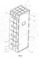
- the container 1 according to the invention is a container which is particularly intended for storing and transporting products under controlled temperature such as fresh products or frozen products.
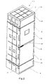
- this container 1 has a box 2 on which a door 3 is hinged; the door 3 is held in the closed position on the body by closing means.
- the box 2 in the examples illustrated in these figures, has a parallelepiped shape which constitutes a common embodiment of the container although other forms can be envisaged.
- the box 2 rests on one of its small faces; the large faces of the body 2 are vertical to the ground.
- the small face which constitutes the base of the box can be provided with four wheels to facilitate the movement of the container 1.
- the body 2 is made of a thermally insulating material.
- the box 2 can be, for example, made in rotomolding with polyethylene walls in which is injected a polyurethane foam. It can also be performed by an assembly of insulating panels. As can be seen in the drawings, there are provided on each wall of the box stiffening ribs.
- the box 2 has, therefore, a rectangular opening in one of its large faces, which can be closed by the door.
- the opening is surrounded by a shoulder 4.
- This shoulder 4 is continuous and extends over the entire periphery of the opening.
- the shoulder 4 is formed in the thickness of the wall of the body 2.
- the opening is also surrounded by a peripheral rib 6.
- This rib 6 may have the peculiarity of being cut by slots 7.
- the slots 7 are present on the two ribs which frame the opening vertically.
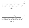
- the door 3 in the embodiments thereof shown in the drawing, the door 3 consists of a core 11 of foam which is sheathed with an impermeable material.
- the soul 11 can be a flexible polyurethane foam and, optionally as shown in Figure 10, it is envisaged to make this core with two layers of foam of different density.
- a 40-millimeter layer with a density of 30 kilograms per cubic meter and a 40-millimeter layer with a density of 16 kilograms per cubic meter. m3.
- the sheath 9 it can be made in a polyester fabric coated with PVC.
- the sheath 9 may be, depending on the case, assembled by sewing, welding or gluing on the core 11 of foam.
- the sheath 9 can still be directly glued to the core 11 of foam.
- transverse and longitudinal dimensions of the door 3 are slightly greater than the dimensions of the opening between the ribs 6.
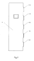
- the waterproof fabric sheath is extended on one side of the door of several sleeves 10, as shown in Figure 7.
- These sleeves 10 have a length less than or equal to that of the slots 7 formed in the ribs 6 of the box, so that, by applying the door against the shoulder 4 made in the box, the sleeves 10 are placed in each of the slots 7, the pin 8 having been previously removed. By engaging the pin 8 in the bores provided for this purpose, it enters each of the sleeves 10 and thus forms a hinge for the door.
- the door 3 has a thickness slightly less than the dimension of the peripheral rib 6. Thus when the door is closed, it is embedded in the body 2 and is thus protected at its periphery by the rib 6.
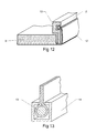
- Figures 12 and 13 show another embodiment of the hinge between the body 2 and the flexible door 3. According to this embodiment, it is planned to extend the sheath 9 of the door 3 by a lateral flap 12 which encloses a rod 13. It is then envisaged to integrate in the box 2, a rod 14 of substantially transverse section. C-shaped in which the ring 13 of the door can be engaged. The door can then rotate relative to the body with this hinge.
- a common point to these closure means is that they are embedded on the door and they use, as a point of attachment, the pin 8 opposite to that forming the hinge of the door thus putting the door in compression against the shoulder .
- FIG. 3 shows three types of closure means.
- the closure means shown in the upper part of FIG. 3 is a strap 16 which has two self-gripping parts 17a, 17b.
- the fixed end of this strap is fixed to the door 3 at its hinge, while its free end can be passed through the pin 8 which appears at a crenel 7 and be folded back on itself to come close thanks to its gripping parts 17a, 17b.
- the closure means illustrated on the intermediate portion of Figure 3, provides a strap 18 also attached to the door whose free end is resilient and having a hook 19 can be caught on the spindle.
- the third closure means shown in Figure 3 shows a strap 20 having a movable hook 21 which can come to grip the pin 8 and a hook 22 to adjust the tension of the strap.
- the door 3 is kept in its closed position, but also it is put in compression with respect to the body 2.
- the door is made of a flexible material , so that the tightening thereof relative to the body causes a crushing of the door 3 at the shoulder 4 on which it rests. This crushing contributes, very importantly, to the sealing of the door relative to the body.
- a tamper-evident strapping 24 which has the function of both closing the door 3 and also preventing an unauthorized opening of the door. it.
- Figure 4 shows an embodiment of the container in which there is provided a single closure means and two straps.
- Figure 5 shows an embodiment in which the upper part and the lower part of the door are closed by a closing means, while the central part is closed by a strapping.
- Figure 6 illustrates an embodiment in which the door is closed by three closing means.
- Figure 14 illustrates another embodiment of the closure means. It can be provided an elastic cord 26 whose two ends are fixed to the same pin 8.
- the elastic cord 26 forms several loops which are guided through openings 28 formed in a band 27 attached to the outer face of the door 3.
- These openings 28 may be either eyelets as shown in Figure 14, or areas in which the strip 27 is peeled from the door 3 as shown in Figure 15.
- the locking of the door 3 can then be done very simply because it is sufficient to fix each of the loops formed by the cord 26, on the rib 6 crenellated to block the door 3.
- Figure 14 further shows a feature that may be useful for retaining the door 3 relative to the body. He may consider providing one of the ribs 6 with a rigid or semi-rigid lip 25. In the example shown, the two transverse ribs 6 are provided with a lip 25 which extends towards the opening; thus during the setting up the door 3, the latter being flexible crushes to pass each of lips 25 and then resumes its normal shape while being blocked by the two lips 25.
- the handling of the container can be done easily by means of one of the pins 8 which, when it appears at the level of the crenellations, constitutes a means of gripping the container.
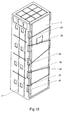
- Figures 16 to 18 illustrate another embodiment of a container which is presented as a "chest” unlike the preceding which is presented as a "cabinet”.
- the door 3 is not articulated on the body 2; it comes to bear against the shoulder 4 and fit between the ribs 6 which surround the opening of the body 2.
- the door 3 has transverse and longitudinal dimensions slightly greater than the dimensions between the ribs 6 so that the door 3 is in compression when it closes the body 2. There is thus on this container the same double sealing as existing in the previously described containers.
- FIG. 19 shows the structure of the door 3.
- This comprises a core 11 of foam and a sheath 9 which can be a polyester tarpaulin coated with PVC.
- the sheath 9 is extended by four flaps 29 which are each equipped with elastic cords 30. Each flap has eyelets through which the cord is passed.
- the fixing of the door 3, once it has been fitted on the body 2, is done by fixing the elastic cord on bosses 31 which protrude from the lateral faces of the body 3.
- the flaps 29 cover the corners of the box which allows to stack several containers without the door 3 is damaged.
- the invention thus provides a container having a flexible door which provides a very good seal with respect to the rigid box of the container.
- the fact that the door is flexible prevents leakage of the seal in case of deformation of the container, for example when it rests on unequal supports.
Abstract
Description
La présente invention concerne un conteneur isotherme, c'est-à-dire un conteneur destiné à transporter des produits à une température constante ou sensiblement constante.The present invention relates to an isothermal container, that is to say a container for conveying products at a constant or substantially constant temperature.
Dans le domaine de la logistique de produits qui doivent être maintenus à température contrôlée, on a souvent recours à des conteneurs isothermes. Les produits en question peuvent être, par exemple, des produits alimentaires ou des produits médicaux.In the field of logistics of products that must be kept at controlled temperature, isothermal containers are often used. The products in question may be, for example, food products or medical products.
Selon les cas, ces conteneurs peuvent intégrer un réservoir cryogénique qui peut recevoir du dioxyde de carbone en phase solide.Depending on the case, these containers may incorporate a cryogenic tank that can receive solid phase carbon dioxide.
Ces conteneurs sont, en particulier, utilisés pour transporter des produits alimentaires, dont la température doit être maintenue dans une certaine plage, depuis un centre logistique jusqu'à un point de vente.These containers are, in particular, used to transport food products, whose temperature must be maintained within a certain range, from a logistics center to a point of sale.
Il importe que les conteneurs assurant le transport de tels produits soient particulièrement isolants et étanches pour éviter des échanges thermiques entre le milieu extérieur et l'intérieur du conteneur. Des fuites auront comme conséquence un réchauffement des produits transportés et, éventuellement, une rupture de la chaîne du froid. Ceci peut, alors, altérer la qualité des produits transportés.It is important that the containers transporting such products are particularly insulating and waterproof to prevent heat exchange between the outside environment and the interior of the container. Leaks will result in a warming of the transported products and possibly a break in the cold chain. This can, therefore, alter the quality of the products transported.
Tout en ayant une capacité d'isolation thermique permettant de transporter des produits depuis un entrepôt jusqu'à un lieu de destination, il est souhaitable de minimiser les coûts d'acquisition et d'utilisation des conteneurs du type précité.While having a thermal insulation capacity to transport products from a warehouse to a destination, it is desirable to minimize the costs of acquiring and using containers of the aforementioned type.
Un but de l'invention est de proposer un conteneur isolant qui présente une structure simple, qui assure une bonne isolation thermique et qui soit d'une maintenance aisée.An object of the invention is to provide an insulating container which has a simple structure, which provides good thermal insulation and easy maintenance.
L'invention a essentiellement pour objet un conteneur isotherme comprenant une caisse pouvant être fermée par une porte. La caisse en matériau isolant rigide sensiblement parallélépipédique présente une ouverture ceinturée par un épaulement périphérique continu et par une nervure périphérique. La porte en matériau isolant souple peut s'emboîter dans l'ouverture de la caisse pour fermer le conteneur, la porte étant alors en compression contre la nervure périphérique. Des moyens de fermeture de la porte peuvent mettre en compression la porte contre l'épaulement.The invention essentially relates to an isothermal container comprising a box that can be closed by a door. The box of substantially parallelepiped rigid insulating material has an opening surrounded by a continuous peripheral shoulder and a peripheral rib. The door of flexible insulating material can fit into the opening of the box to close the container, the door then being in compression against the peripheral rib. Means for closing the door can compress the door against the shoulder.
Le fondement de l'invention réside essentiellement dans la combinaison d'une caisse rigide et d'une porte souple en matériau peu coûteux mais qui réalise une excellente étanchéité avec la caisse. Cette étanchéité est obtenue, d'une part, par le fait que la porte est mise compression contre la nervure périphérique et, d'autre part, par la mise en compression de la porte contre l'épaulement. Grâce à la souplesse de la porte, il est crée une double étanchéité par rapport à l'épaulement et par rapport à la nervure qui bordent l'ouverture et, ce, sans avoir à recourir à un joint d'étanchéité rapporté. On doit également mentionner que la souplesse de la porte permet de conserver l'étanchéité entre celle-ci et la caisse même lorsque la caisse est déformée à la suite de chocs dus à sa manutention, à l'usure de ses matériaux, ou éventuellement lorsqu'elle repose sur une surface inégale.The basis of the invention lies essentially in the combination of a rigid body and a flexible door of inexpensive material but which achieves an excellent seal with the body. This sealing is obtained on the one hand, by the fact that the door is placed compression against the peripheral rib and, secondly, by the compression of the door against the shoulder. Thanks to the flexibility of the door, it creates a double seal with respect to the shoulder and with respect to the rib which border the opening and, without having to resort to a reported seal. It should also be mentioned that the flexibility of the door makes it possible to maintain the seal between the latter and the box even when the box is deformed as a result of shocks due to its handling, the wear of its materials, or possibly when it rests on an uneven surface.
Dans une forme de réalisation du conteneur, il peut être prévu qu'il comprenne des moyens d'articulation permettant la pivotement de la porte par rapport à la caisse, entre une position d'ouverture dans laquelle la porte dégage un accès à l'ouverture et une position de fermeture dans laquelle la porte ferme l'ouverture et vient en appui contre l'épaulement.In one embodiment of the container, it may be provided that it comprises hinge means for pivoting the door relative to the body, between an open position in which the door releases access to the opening and a closed position in which the door closes the opening and bears against the shoulder.
Selon une disposition avantageuse, la nervure présente, sur au moins un côté de l'ouverture, au moins un créneau.According to an advantageous arrangement, the rib has, on at least one side of the opening, at least one slot.
De plus, une broche peut être engagée dans la nervure crénelée, la broche étant apparente au niveau de chaque créneau.In addition, a pin can be engaged in the crenellated rib, the pin being apparent at each slot.
Selon une caractéristique particulièrement avantageuse, la porte présente au moins un fourreau, de longueur au plus égale à celle d'un créneau, positionné sur un bord de la porte dans lequel la broche est susceptible d'être engagée pour former une charnière. La porte est ainsi articulée sur la caisse par une liaison très simple et fiable qui, notamment, ne présente pas de pièce mécanique en mouvement. Grâce à cette liaison, la maintenance du conteneur est, de plus, très simple puisque un changement de porte se fait simplement en retirant la broche ce qui a pour effet immédiat la libération de la porte. Cette opération de maintenance peut se faire par un personnel sans qualification particulière.According to a particularly advantageous characteristic, the door has at least one sleeve, of length at most equal to that of a slot, positioned on an edge of the door in which the pin can be engaged to form a hinge. The door is thus articulated on the body by a very simple and reliable connection which, in particular, does not present a moving mechanical part. Thanks to this connection, the maintenance of the container is, moreover, very simple since a door change is simply by removing the pin which has the immediate effect of the release of the door. This maintenance operation can be done by a staff without special qualifications.
Selon une autre forme de réalisation, la porte présente, sur l'un de ses bords, un panneau souple intégrant un jonc pouvant être engagé dans un rail de section transversale en forme de C intégré au conteneur, ce qui constitue également une liaison très simple et fiable.According to another embodiment, the door has, on one of its edges, a flexible panel incorporating a rod that can be engaged in a C-shaped cross section rail integrated in the container, which also constitutes a very simple connection and reliable.
Selon plusieurs possibilités d'exécution des moyens de fermeture de la porte :
- ceux-ci peuvent comprendre une sangle recevant des panneau de textile auto agrippant pouvant être rabattue et fixée sur elle-même après passage autour d'une broche,
- ceux-ci peuvent comprendre une sangle dont une extrémité est fixée à la porte et dont l'extrémité libre constituée d'un matériau élastique reçoit un crochet pouvant venir agripper une broche opposée à la broche formant charnière.
- ceux-ci peuvent comprendre une sangle ayant un crochet mobile pouvant venir agripper une broche opposée à la broche formant charnière et un crochet de serrage permettant de régler la tension de la sangle.
- ceux-ci comprennent un cordon élastique dont les deux extrémités sont liées à une broche, le cordon formant au moins une boucle pouvant venir se fixer sur un créneau du coté de la caisse opposé au coté sur lequel sont fixés les extrémités du cordon. De façon avantageuse, il peut être alors prévu que la porte présente, sur sa face extérieure, une bande parallèle à chaque broche, dans laquelle sont ménagées des ouvertures permettant le guidage de chaque boucle.
- these may comprise a strap receiving textile panel self-gripping that can be folded and fixed on itself after passing around a pin,
- these may comprise a strap whose one end is fixed to the door and whose free end made of a resilient material receives a hook that can catch a pin opposite to the pin forming hinge.
- these may comprise a strap having a movable hook that can grip a pin opposite to the hinge pin and a clamping hook for adjusting the tension of the strap.
- these comprise an elastic cord whose two ends are connected to a pin, the cord forming at least one loop being able to be fixed on a crenel on the side of the box opposite the side on which are fixed the ends of the cord. Advantageously, it may be then provided that the door has, on its outer face, a strip parallel to each pin, in which are provided openings for guiding each loop.
Selon une possibilité préférée, la porte est constituée d'une âme de mousse isolante recouverte d'une gaine d'un matériau imperméable.According to a preferred possibility, the door consists of an insulating foam core covered with a sheath of impermeable material.
Il est également envisagé, que l'âme comprenne au moins deux couches superposées de mousse isolante de différente densité, la mousse de plus faible densité étant destinée à être en contact de l'épaulement en position fermée de la porte.It is also envisaged that the core comprises at least two superimposed layers of insulating foam of different density, the lower density foam being intended to be in contact with the shoulder in the closed position of the door.
Dans une autre forme de réalisation de la porte, notamment dans le cas où celle-ci n'est pas articulée sur la caisse, la porte présente sur chacun de ses cotés un rabat qui reçoit un cordon élastique pouvant venir s'accrocher sur une saillie dépassant de la caisse.In another embodiment of the door, particularly in the case where it is not hinged to the body, the door has on each of its sides a flap that receives an elastic cord that can hang on a projection exceeding the box.
Pour assurer un meilleur maintien de la porte par rapport à la caisse, il peut être prévu que, au moins l'une des nervures présente une lèvre dirigée vers l'ouverture permettant de bloquer la porte en position de fermeture.To ensure a better hold of the door relative to the body, it can be provided that at least one of the ribs has a lip directed towards the opening for locking the door in the closed position.
Pour sa bonne compréhension, l'invention est décrite en référence au dessin ci annexé représentant, à titre d'exemple non limitatif, plusieurs formes de réalisation d'un conteneur isotherme selon l'invention.
- Figure 1 est une vue en perspective d'une première forme de réalisation de ce conteneur,
- Figure 2 représente le même conteneur que celui représenté à la figure 1, équipé de moyens de fermeture,
- Figure 3 montre, en perspective, plusieurs possibilités de réalisation de ces moyens de fermeture,
- Figures 4, 5 et 6 montrent, en vue de face, un conteneur selon l'invention équipé de différentes formes d'exécution de ses moyens de fermeture,
- Figure 7 montre, en vue de face, une porte du conteneur selon l'invention,
- Figure 8 est une vue en coupe selon VIII-VIII de figure 1,
- Figures 9 et 10 montrent, en coupe deux formes d'exécution de la porte,
- Figure 11 montre, en perspective avec arrachement partiel, une forme d'articulation de la porte par rapport à la caisse du conteneur,
- Figures 12 et 13 montrent une autre possibilité de réalisation de la charnière entre la porte et la caisse,
- Figures 14 montre en perspective un conteneur ayant une autre forme de réalisation des moyens.de fermeture,
- Figure 1 5 montre en perspective une variante d'exécution de la porte équipant le conteneur représenté à la Figure 14,
- Figures 16, 17, 18 montrent respectivement en vue de face, en vue de dessus et en coupe une autre forme de réalisation d'un conteneur
- Figure 19 montre en vue éclatée la porte équipant le conteneur représenté aux Figures 16, 17 et 18.
- Figure 1 is a perspective view of a first embodiment of this container,
- FIG. 2 represents the same container as that represented in FIG. 1, equipped with closure means,
- Figure 3 shows, in perspective, several possibilities of realization of these means of closure,
- Figures 4, 5 and 6 show, in front view, a container according to the invention equipped with different embodiments of its closure means,
- FIG. 7 shows, in front view, a door of the container according to the invention,
- Figure 8 is a sectional view according to VIII-VIII of Figure 1,
- Figures 9 and 10 show, in section two embodiments of the door,
- Figure 11 shows, in perspective partially broken away, a form of articulation of the door relative to the container body,
- Figures 12 and 13 show another possible embodiment of the hinge between the door and the body,
- Figures 14 shows in perspective a container having another embodiment of the closing means,
- Figure 1 shows in perspective an alternative embodiment of the door equipping the container shown in Figure 14,
- Figures 16, 17, 18 show respectively in front view, in plan view and in section another embodiment of a container
- Figure 19 shows in exploded view the door equipping the container shown in Figures 16, 17 and 18.
Il est précisé que les éléments communs aux différentes formes de réalisation portent les mêmes références numériques.It is specified that the elements common to the various embodiments have the same reference numerals.
Le conteneur 1 selon l'invention est un conteneur qui est notamment destiné à stocker et à transporter des produits sous température dirigée tels que produits frais ou des produits surgelés.The
Comme on peut le voir sur la figure 1 ou sur la figure 2, ce conteneur 1 présente une caisse 2 sur laquelle une porte 3 est articulée ; la porte 3 est maintenue en position de fermeture sur la caisse par des moyens de fermeture.As can be seen in FIG. 1 or in FIG. 2, this
La caisse 2, dans les exemples illustrés sur ces figures, présente une forme parallélépipédique qui constitue une forme de réalisation commune du conteneur bien que d'autres formes puissent être envisagées. Dans l'exemple représenté, la caisse 2 repose sur l'une de ses petites faces ; les grandes faces de la caisse 2 sont à la verticale par rapport au sol. Bien que cela ne soit pas représenté sur le dessin, la petite face qui constitue la base de la caisse peut être munie de quatre roulettes pour faciliter le déplacement du conteneur 1.The
La caisse 2 est réalisée dans un matériau thermiquement isolant. La caisse 2 peut être, par exemple, réalisée en rotomoulage avec des parois en polyéthylène dans lesquelles est injectée une mousse de polyuréthane. Elle peut être également réalisée par un assemblage de panneaux isolants. Comme on peut le voir sur les dessins, il est prévu sur chacune des parois de la caisse des nervures de rigidification.The
La caisse 2 présente, donc, une ouverture rectangulaire dans une de ses grandes faces, qui peut être obturée par la porte.The
En se référant aux figures 3, 8 et 11, on peut voir que l'ouverture est ceinturée par un épaulement 4. Cet épaulement 4 est continu et s'étend sur toute la périphérie de l'ouverture. Dans l'exemple représenté, l'épaulement 4 est ménagé dans l'épaisseur de la paroi de la caisse 2.Referring to Figures 3, 8 and 11, it can be seen that the opening is surrounded by a
On note également, et on peut se reporter aux figures précitées, que l'ouverture est également ceinturée par une nervure 6 périphérique. Cette nervure 6 peut présenter la particularité d'être entaillée par des créneaux 7. Dans l'exemple représenté sur les figures, les créneaux 7 sont présents sur les deux nervures qui encadrent verticalement l'ouverture.It is also noted, and it can be seen in the above figures, that the opening is also surrounded by a
Comme cela apparaît sur les figures, on note, en outre, la présence de deux broches 8 qui viennent chacune s'engager dans un alésage réalisé dans chacune des nervures 6 verticales qui bordent l'ouverture.As shown in the figures, there is, in addition, the presence of two
Du fait de la présence des créneaux 7 dans chacune des nervures 6 verticales, la broche 8 est donc apparente au niveau de chaque créneau 7. La fonction de ces deux broches apparaîtra plus loin.Due to the presence of the
En ce qui concerne la porte 3, dans les exemples de réalisation de celle-ci représentés sur le dessin, la porte 3 est constituée d'une âme 11 de mousse qui est gainée d'un matériau imperméable. L'âme 11 peut être une mousse polyuréthane souple et, éventuellement comme le montre la figure 10, il est envisagé de réaliser cette âme avec deux couches superposées de mousse de densité différente. A titre d'exemple, pour une porte d'épaisseur de 80 millimètres, il est possible d'envisager une couche de 40 millimètres dont la densité serait de 30 kilogrammes par m3 et une couche de 40 millimètres dont la densité serait de 16 kilogrammes par m3.Regarding the
Pour ce qui est de la gaine 9, celle-ci peut être réalisée dans un tissu polyester enduit de PVC. La gaine 9 peut être, selon les cas, assemblée par couture, soudure ou collage sur l'âme 11 de mousse. La gaine 9 peut encore être directement collée sur l'âme 11 de mousse.As regards the
Il est important de préciser que les dimensions transversale et longitudinale de la porte 3 sont légèrement supérieures aux dimensions de l'ouverture entre les nervures 6.It is important to specify that the transverse and longitudinal dimensions of the
On remarque que la gaine de tissu imperméable est prolongée sur l'un des côtés de la porte de plusieurs fourreaux 10, ce que montre la figure 7. Ces fourreaux 10 présentent une longueur inférieure ou égale à celle des créneaux 7 ménagés dans les nervures 6 de la caisse, de sorte que, en appliquant la porte contre l'épaulement 4 réalisé dans la caisse, les fourreaux 10 viennent se placer dans chacun des créneaux 7, la broche 8 ayant été préalablement retirée. En engageant la broche 8 dans les alésages prévus à cet effet, celle-ci rentre dans chacun des fourreaux 10 et forme ainsi une charnière pour la porte.Note that the waterproof fabric sheath is extended on one side of the door of
On voit donc que l'on a réalisé, de manière simple, une charnière permettant le pivotement de la porte 3 par rapport à la caisse 2 d'un conteneur.It can thus be seen that a hinge has been made in a simple manner for pivoting the
De plus, en cas d'endommagement ou d'usure de la porte 3, le retrait et le remplacement de celle-ci se fait de manière très simple puisqu'il suffit de retirer la broche 8 pour retirer la porte de la caisse et en assurer le remplacement.In addition, in case of damage or wear of the
Dans l'exemple illustré, la porte 3 présente une épaisseur légèrement inférieure à la cote de la nervure 6 périphérique. Ainsi lorsque la porte est fermée, elle est encastrée dans la caisse 2 et est donc protégée à sa périphérie par la nervure 6.In the example shown, the
Un point important qu'il convient de faire ressortir est que la porte 3 repose sur l'épaulement 4 ménagé dans la caisse et repose également sur les nervures 6. Du fait de ses dimensions, la porte doit être comprimée pour être emboîtée entre les nervures 6.An important point that should be highlighted is that the
Il est ainsi créer un double contact surfacique qui s'avère extrêmement favorable pour l'étanchéité du conteneur. Cette étanchéité est réalisée par le fait que la porte 3 elle-même est en un matériau souple.It is thus creating a double surface contact which is extremely favorable for the sealing of the container. This sealing is achieved by the fact that the
Ainsi, il n'est pas utile de rapporter un joint spécifique pour réaliser l'étanchéité. On doit noter que, dans le cas d'une porte ayant une âme 11 constituée de mousse de plusieurs densités, on placera avantageusement la mousse ayant la densité la plus faible en regard de l'intérieur de la caisse, de façon à ce que la mousse qui présente la souplesse la plus importante puisse venir s'écraser contre l'épaulement 4 et fournir le contact surfacique le meilleur possible pour créer, de ce fait, l'étanchéité la meilleure possible.Thus, it is not useful to report a specific seal to achieve sealing. It should be noted that, in the case of a door having a core 11 made of foam of several densities, it will be advantageous to place the foam having the lowest density opposite the inside of the box, so that the The foam that has the greatest flexibility can crash against the
Les figures 12 et 13 montrent une autre forme de réalisation de la charnière entre la caisse 2 et la porte 3 souple. Selon cette forme de réalisation, il est prévu de prolonger la gaine 9 de la porte 3 par un rabat 12 latéral qui enferme un jonc 13. Il est prévu, alors, d'intégrer à la caisse 2, un rait 14 de section transversale sensiblement en forme de C dans lequel le jonc 13 de la porte peut être engagé. La porte peut alors pivoter par rapport à la caisse grâce à cette charnière.Figures 12 and 13 show another embodiment of the hinge between the
Il faut également mentionner les moyens de fermeture de la porte qui permettent de maintenir celle-ci en position fermée. A cet égard, il est prévu plusieurs types de moyens de fermeture, comme le montrent les figures 3, 4, 5, 6.Mention must also be made of the means for closing the door which make it possible to keep the latter in the closed position. In this respect, several types of closure means are provided, as shown in FIGS. 3, 4, 5, 6.
Un point commun à ces moyens de fermeture est qu'ils sont embarqués sur la porte et qu'ils utilisent, comme point d'attache, la broche 8 opposée à celle formant charnière de la porte mettant ainsi la porte en compression contre l'épaulement.A common point to these closure means is that they are embedded on the door and they use, as a point of attachment, the
La figure 3 montre trois types de moyens de fermeture. Le moyen de fermeture représenté sur la partie supérieure de la figure 3 est une sangle 16 qui présente deux pièces auto agrippantes 17a, 17b. L'extrémité fixe de cette sangle est fixée à la porte 3 au niveau de sa charnière, tandis que son extrémité libre peut être passée dans la broche 8 qui apparaît au niveau d'un créneau 7 et être repliée sur elle-même pour venir se fermer grâce à ses pièces auto agrippantes 17a, 17b.Figure 3 shows three types of closure means. The closure means shown in the upper part of FIG. 3 is a
Le moyen de fermeture, illustré sur la partie intermédiaire de la figure 3, prévoit une sangle 18 fixée également sur la porte dont l'extrémité libre est élastique et qui présente un crochet 19 pouvant venir se prendre sur la broche.The closure means, illustrated on the intermediate portion of Figure 3, provides a
Enfin, le troisième moyen de fermeture représenté sur la figure 3 montre une sangle 20 ayant un crochet mobile 21 qui peut venir s'agripper sur la broche 8 et un crochet 22 permettant de régler la tension de cette sangle.Finally, the third closure means shown in Figure 3 shows a
Un point important commun à tous les moyens de fermeture est que ceux-ci permettent d'imprimer une compression permanente à la porte et ainsi de garantir l'étanchéité entre la caisse et la porte pendant toutes les opérations de manutention et de transport.An important point common to all means of closure is that they can print a permanent compression to the door and thus ensure the seal between the body and the door during all handling and transport operations.
En d'autres termes, grâce à ces moyens de fermeture, non seulement la porte 3 est maintenue dans sa position fermée, mais de plus elle est mise en compression par rapport à la caisse 2. Or, la porte est réalisée dans un matériau souple, ce qui fait que le serrage de celle-ci par rapport à la caisse provoque un écrasement de la porte 3 au niveau de l'épaulement 4 sur lequel elle repose. Cet écrasement contribue, de manière très importante, à l'étanchéité de la porte par rapport à la caisse.In other words, thanks to these closing means, not only the
On note également qu'il est possible de réaliser la fermeture de la porte par un cerclage d'inviolabilité 24 qui a, pour fonction, à la fois d'assurer la fermeture de la porte 3 et également d'interdire une ouverture non autorisée de celle-ci.It is also noted that it is possible to close the door by a tamper-evident strapping 24 which has the function of both closing the
La figure 4 montre une forme de réalisation du conteneur dans laquelle il est prévu un unique moyen de fermeture et deux cerclages.Figure 4 shows an embodiment of the container in which there is provided a single closure means and two straps.
La figure 5 montre une forme de réalisation dans laquelle la partie supérieure et la partie inférieure de la porte sont fermées par un moyen de fermeture, tandis que la partie centrale est fermée par un cerclage.Figure 5 shows an embodiment in which the upper part and the lower part of the door are closed by a closing means, while the central part is closed by a strapping.
La figure 6 illustre une forme de réalisation dans laquelle la porte est fermée par trois moyens de fermeture.Figure 6 illustrates an embodiment in which the door is closed by three closing means.
La figure 14 illustre une autre forme de réalisation des moyens de fermeture. Il peut être prévu un cordon élastique 26 dont les deux extrémités sont fixées à une même broche 8. Le cordon élastique 26 forme plusieurs boucles qui sont guidées en passant au travers d'ouvertures 28 formées dans une bande 27 rapportée sur la face extérieure de la porte 3. Ces ouvertures 28 peuvent être soit des oeillets comme le montre la figure 14, soit des zones dans lesquelles la bande 27 est décollée de la porte 3 comme le montre la figure 15. Le verrouillage de la porte 3 peut alors se faire très simplement puisque qu'il suffit de fixer chacune des boucles formées par le cordon 26, sur la nervure 6 crénelée pour bloquer la porte 3.Figure 14 illustrates another embodiment of the closure means. It can be provided an
La figure 14 montre de plus une caractéristique qui peut être utile pour la retenue de la porte 3 par rapport à la caisse. Il peut envisager de doter l'une des nervures 6 d'une lèvre 25 rigide ou semi rigide. Dans l'exemple représenté, les deux nervures 6 transversales sont pourvues d'une lèvre 25 qui s'étend en direction de l'ouverture ; ainsi lors de la mise en place la porte 3, celle-ci étant souple s'écrase pour passer chacune de lèvres 25 et reprend ensuite sa forme normale tout en étant bloquer par les deux lèvres 25.Figure 14 further shows a feature that may be useful for retaining the
On peut également noter que le maniement du conteneur peut se faire aisément grâce à l'une des broches 8 qui, lorsqu'elle apparaît au niveau des créneaux, constitue un moyen de préhension du conteneur.It may also be noted that the handling of the container can be done easily by means of one of the
Les figures 16 à 18 illustrent une autre forme de réalisation d'un conteneur qui se présente comme un « coffre » contrairement au précèdent qui se présente comme une « armoire ».Figures 16 to 18 illustrate another embodiment of a container which is presented as a "chest" unlike the preceding which is presented as a "cabinet".
Dans cette forme de réalisation, la porte 3 n'est pas articulée sur la caisse 2 ; celle-ci vient s'appuyer contre l'épaulement 4 et s'emboîter entre les nervures 6 qui ceinturent l'ouverture de la caisse 2. La porte 3 présente des dimensions transversale et longitudinale légèrement supérieures aux dimensions séparant les nervures 6 pour que la porte 3 soit en compression lorsqu'elle ferme la caisse 2. On retrouve ainsi sur ce conteneur la même double étanchéité que celle existant dans les conteneurs précédemment décrits.In this embodiment, the
La figure 19 montre la structure de la porte 3. Celle-ci comprend une âme 11 de mousse et une gaine 9 pouvant être une bâche de polyester enduit de PVC. On peut remarquer que la gaine 9 est prolongée de quatre rabats 29 qui chacun sont équipés de cordons élastiques 30. Chaque rabat présente des oeillets au travers desquels le cordon est passé. La fixation de la porte 3, une fois que celle-ci a été emboîté sur la caisse 2, se fait en fixant le cordon élastique sur des bossages 31 qui dépassent des faces latérales de la caisse 3.FIG. 19 shows the structure of the
Comme le montre la figure 17, les rabats 29 ne couvrent les coins de la caisse ce qui permet de superposer plusieurs conteneurs sans que la porte 3 ne soit endommagée.As shown in Figure 17, the
L'invention fournit ainsi un conteneur présentant une porte souple qui réalise une très bonne étanchéité par rapport à la caisse rigide du conteneur.The invention thus provides a container having a flexible door which provides a very good seal with respect to the rigid box of the container.
Corollairement, le fait que la porte soit souple permet d'éviter des pertes de l'étanchéité en cas de déformation du conteneur, par exemple lorsque celui-ci repose sur des appuis inégaux.As a corollary, the fact that the door is flexible prevents leakage of the seal in case of deformation of the container, for example when it rests on unequal supports.
Bien entendu, l'invention n'est pas limitée à la forme de réalisation décrite ci-dessus à titre d'exemple, mais elle en embrasse toutes les formes de réalisation.Of course, the invention is not limited to the embodiment described above by way of example, but it embraces all embodiments.
Claims (15)
Applications Claiming Priority (1)
| Application Number | Priority Date | Filing Date | Title |
|---|---|---|---|
| FR0502079A FR2882733B1 (en) | 2005-03-01 | 2005-03-01 | ISOTHERMAL CONTAINER |
Publications (2)
| Publication Number | Publication Date |
|---|---|
| EP1698568A1 true EP1698568A1 (en) | 2006-09-06 |
| EP1698568B1 EP1698568B1 (en) | 2007-08-29 |
Family
ID=35149432
Family Applications (1)
| Application Number | Title | Priority Date | Filing Date |
|---|---|---|---|
| EP06356015A Not-in-force EP1698568B1 (en) | 2005-03-01 | 2006-02-15 | Isothermal container |
Country Status (5)
| Country | Link |
|---|---|
| EP (1) | EP1698568B1 (en) |
| AT (1) | ATE371609T1 (en) |
| DE (1) | DE602006000085T2 (en) |
| ES (1) | ES2293633T3 (en) |
| FR (1) | FR2882733B1 (en) |
Citations (7)
| Publication number | Priority date | Publication date | Assignee | Title |
|---|---|---|---|---|
| US3160307A (en) * | 1962-07-13 | 1964-12-08 | Willard L Morrison | Insulated shipper container |
| US3605433A (en) * | 1969-11-10 | 1971-09-20 | John Strathaus | Salad bowl |
| US4161261A (en) * | 1978-05-05 | 1979-07-17 | Menasha Corporation | Security container |
| US5009081A (en) * | 1988-07-12 | 1991-04-23 | Whirlpool Corporation | Modular mechanical refrigeration unit |
| WO1992015507A1 (en) * | 1991-03-05 | 1992-09-17 | Eurotainer Ab | Shipping container for goods sensitive of temperature |
| US6134906A (en) * | 1999-05-31 | 2000-10-24 | Eastman; Winthrop A. | Refrigerator with video monitor workstation |
| US6244066B1 (en) * | 2000-05-01 | 2001-06-12 | Larose Aaron J. | Floating cooler |
-
2005
- 2005-03-01 FR FR0502079A patent/FR2882733B1/en not_active Expired - Fee Related
-
2006
- 2006-02-15 DE DE602006000085T patent/DE602006000085T2/en active Active
- 2006-02-15 ES ES06356015T patent/ES2293633T3/en active Active
- 2006-02-15 AT AT06356015T patent/ATE371609T1/en not_active IP Right Cessation
- 2006-02-15 EP EP06356015A patent/EP1698568B1/en not_active Not-in-force
Patent Citations (7)
| Publication number | Priority date | Publication date | Assignee | Title |
|---|---|---|---|---|
| US3160307A (en) * | 1962-07-13 | 1964-12-08 | Willard L Morrison | Insulated shipper container |
| US3605433A (en) * | 1969-11-10 | 1971-09-20 | John Strathaus | Salad bowl |
| US4161261A (en) * | 1978-05-05 | 1979-07-17 | Menasha Corporation | Security container |
| US5009081A (en) * | 1988-07-12 | 1991-04-23 | Whirlpool Corporation | Modular mechanical refrigeration unit |
| WO1992015507A1 (en) * | 1991-03-05 | 1992-09-17 | Eurotainer Ab | Shipping container for goods sensitive of temperature |
| US6134906A (en) * | 1999-05-31 | 2000-10-24 | Eastman; Winthrop A. | Refrigerator with video monitor workstation |
| US6244066B1 (en) * | 2000-05-01 | 2001-06-12 | Larose Aaron J. | Floating cooler |
Also Published As
| Publication number | Publication date |
|---|---|
| FR2882733A1 (en) | 2006-09-08 |
| ES2293633T3 (en) | 2008-03-16 |
| ATE371609T1 (en) | 2007-09-15 |
| DE602006000085D1 (en) | 2007-10-11 |
| FR2882733B1 (en) | 2007-05-11 |
| DE602006000085T2 (en) | 2008-05-21 |
| EP1698568B1 (en) | 2007-08-29 |
Similar Documents
| Publication | Publication Date | Title |
|---|---|---|
| EP3883859B1 (en) | Package comprising means for retaining an object | |
| EP3110677B1 (en) | Isothermal container for the preservation of various materials | |
| CA2664897C (en) | Novel shielded container structure for the transport and storage of a radioactive source for medical use | |
| FR3092829A1 (en) | Parcel including means for retaining an object | |
| FR2987573A1 (en) | CASE FOR HAND TOOLS AND ENERGIZED TOOLS | |
| EP1698568B1 (en) | Isothermal container | |
| EP2345601B1 (en) | Enveloppe with protection for fragile items | |
| EP2933400A1 (en) | Device for protecting a tangible asset and use of such a device for protecting a tangible asset | |
| FR2887859A1 (en) | BAG OF CONDITIONINGS OF ARTICLES | |
| EP0539300B1 (en) | Door closure device for insulated containers | |
| FR2827262A1 (en) | Sectional thermally insulated container consists of base and two vertical panel sub-assemblies with semi-rigid insulating complex | |
| EP1830675A1 (en) | Bag for transporting goods | |
| FR2837806A1 (en) | Folding roof for e.g. trailer comprises hinged panels with rollers on their edges which move on rails mounted inside frame on rim of trailer, locking system allowing panels to be opened in either direction | |
| FR2717782A1 (en) | Protection package for blood transfer pouch | |
| EP2221229A1 (en) | Transporting device for a folded tent or other voluminous similar item | |
| FR2950031A1 (en) | Package for transporting and dispatching objects i.e. postal, has side beams including integration units for integrating cover by providing pressure to base plate, where beams supports pressure applied to integrate cover with side walls | |
| FR3010054A1 (en) | CONTAINER FOR HANDLING PRODUCTS | |
| FR3053031B1 (en) | PERFECTION OF COVER RECIPIENT | |
| EP3242837B1 (en) | Logistics module | |
| FR2861027A1 (en) | Tarpaulin for closing e.g. truck, has belts tensioning canvas, where each belt is associated with coupling device fixed on inner side of canvas and has hook to contact with lower plate | |
| WO2023036694A1 (en) | Parcel comprising means for retaining at least one object | |
| WO2024056474A1 (en) | Package incorporating means for retaining objects | |
| EP0900535A1 (en) | Bag-type luggage element convertible in a backpack and vice-versa | |
| FR2841536A1 (en) | Cover for goods trolley has one side which is attached to its two neighbors by sliding clasp fasteners, base flap fitting under trolley and having eyelets allowing its edge to be fastened to slides of fasteners | |
| FR2744601A1 (en) | Foldable carrier bag |
Legal Events
| Date | Code | Title | Description |
|---|---|---|---|
| PUAI | Public reference made under article 153(3) epc to a published international application that has entered the european phase |
Free format text: ORIGINAL CODE: 0009012 |
|
| AK | Designated contracting states |
Kind code of ref document: A1 Designated state(s): AT BE BG CH CY CZ DE DK EE ES FI FR GB GR HU IE IS IT LI LT LU LV MC NL PL PT RO SE SI SK TR |
|
| AX | Request for extension of the european patent |
Extension state: AL BA HR MK YU |
|
| 17P | Request for examination filed |
Effective date: 20070202 |
|
| GRAP | Despatch of communication of intention to grant a patent |
Free format text: ORIGINAL CODE: EPIDOSNIGR1 |
|
| AKX | Designation fees paid |
Designated state(s): AT BE BG CH CY CZ DE DK EE ES FI FR GB GR HU IE IS IT LI LT LU LV MC NL PL PT RO SE SI SK TR |
|
| GRAS | Grant fee paid |
Free format text: ORIGINAL CODE: EPIDOSNIGR3 |
|
| GRAA | (expected) grant |
Free format text: ORIGINAL CODE: 0009210 |
|
| AK | Designated contracting states |
Kind code of ref document: B1 Designated state(s): AT BE BG CH CY CZ DE DK EE ES FI FR GB GR HU IE IS IT LI LT LU LV MC NL PL PT RO SE SI SK TR |
|
| REG | Reference to a national code |
Ref country code: GB Ref legal event code: FG4D Free format text: NOT ENGLISH |
|
| REG | Reference to a national code |
Ref country code: CH Ref legal event code: EP |
|
| REG | Reference to a national code |
Ref country code: IE Ref legal event code: FG4D Free format text: LANGUAGE OF EP DOCUMENT: FRENCH |
|
| REF | Corresponds to: |
Ref document number: 602006000085 Country of ref document: DE Date of ref document: 20071011 Kind code of ref document: P |
|
| REG | Reference to a national code |
Ref country code: SE Ref legal event code: TRGR |
|
| GBT | Gb: translation of ep patent filed (gb section 77(6)(a)/1977) |
Effective date: 20071205 |
|
| PG25 | Lapsed in a contracting state [announced via postgrant information from national office to epo] |
Ref country code: IS Free format text: LAPSE BECAUSE OF FAILURE TO SUBMIT A TRANSLATION OF THE DESCRIPTION OR TO PAY THE FEE WITHIN THE PRESCRIBED TIME-LIMIT Effective date: 20071229 Ref country code: NL Free format text: LAPSE BECAUSE OF FAILURE TO SUBMIT A TRANSLATION OF THE DESCRIPTION OR TO PAY THE FEE WITHIN THE PRESCRIBED TIME-LIMIT Effective date: 20070829 Ref country code: FI Free format text: LAPSE BECAUSE OF FAILURE TO SUBMIT A TRANSLATION OF THE DESCRIPTION OR TO PAY THE FEE WITHIN THE PRESCRIBED TIME-LIMIT Effective date: 20070829 Ref country code: LT Free format text: LAPSE BECAUSE OF FAILURE TO SUBMIT A TRANSLATION OF THE DESCRIPTION OR TO PAY THE FEE WITHIN THE PRESCRIBED TIME-LIMIT Effective date: 20070829 |
|
| NLV1 | Nl: lapsed or annulled due to failure to fulfill the requirements of art. 29p and 29m of the patents act | ||
| PG25 | Lapsed in a contracting state [announced via postgrant information from national office to epo] |
Ref country code: PL Free format text: LAPSE BECAUSE OF FAILURE TO SUBMIT A TRANSLATION OF THE DESCRIPTION OR TO PAY THE FEE WITHIN THE PRESCRIBED TIME-LIMIT Effective date: 20070829 Ref country code: AT Free format text: LAPSE BECAUSE OF FAILURE TO SUBMIT A TRANSLATION OF THE DESCRIPTION OR TO PAY THE FEE WITHIN THE PRESCRIBED TIME-LIMIT Effective date: 20070829 |
|
| REG | Reference to a national code |
Ref country code: ES Ref legal event code: FG2A Ref document number: 2293633 Country of ref document: ES Kind code of ref document: T3 |
|
| PG25 | Lapsed in a contracting state [announced via postgrant information from national office to epo] |
Ref country code: LV Free format text: LAPSE BECAUSE OF FAILURE TO SUBMIT A TRANSLATION OF THE DESCRIPTION OR TO PAY THE FEE WITHIN THE PRESCRIBED TIME-LIMIT Effective date: 20070829 |
|
| REG | Reference to a national code |
Ref country code: IE Ref legal event code: FD4D |
|
| PG25 | Lapsed in a contracting state [announced via postgrant information from national office to epo] |
Ref country code: GR Free format text: LAPSE BECAUSE OF FAILURE TO SUBMIT A TRANSLATION OF THE DESCRIPTION OR TO PAY THE FEE WITHIN THE PRESCRIBED TIME-LIMIT Effective date: 20071130 Ref country code: DK Free format text: LAPSE BECAUSE OF FAILURE TO SUBMIT A TRANSLATION OF THE DESCRIPTION OR TO PAY THE FEE WITHIN THE PRESCRIBED TIME-LIMIT Effective date: 20070829 |
|
| PG25 | Lapsed in a contracting state [announced via postgrant information from national office to epo] |
Ref country code: CZ Free format text: LAPSE BECAUSE OF FAILURE TO SUBMIT A TRANSLATION OF THE DESCRIPTION OR TO PAY THE FEE WITHIN THE PRESCRIBED TIME-LIMIT Effective date: 20070829 Ref country code: SK Free format text: LAPSE BECAUSE OF FAILURE TO SUBMIT A TRANSLATION OF THE DESCRIPTION OR TO PAY THE FEE WITHIN THE PRESCRIBED TIME-LIMIT Effective date: 20070829 Ref country code: IE Free format text: LAPSE BECAUSE OF FAILURE TO SUBMIT A TRANSLATION OF THE DESCRIPTION OR TO PAY THE FEE WITHIN THE PRESCRIBED TIME-LIMIT Effective date: 20070829 Ref country code: PT Free format text: LAPSE BECAUSE OF FAILURE TO SUBMIT A TRANSLATION OF THE DESCRIPTION OR TO PAY THE FEE WITHIN THE PRESCRIBED TIME-LIMIT Effective date: 20080129 |
|
| PG25 | Lapsed in a contracting state [announced via postgrant information from national office to epo] |
Ref country code: RO Free format text: LAPSE BECAUSE OF FAILURE TO SUBMIT A TRANSLATION OF THE DESCRIPTION OR TO PAY THE FEE WITHIN THE PRESCRIBED TIME-LIMIT Effective date: 20070829 |
|
| PLBE | No opposition filed within time limit |
Free format text: ORIGINAL CODE: 0009261 |
|
| STAA | Information on the status of an ep patent application or granted ep patent |
Free format text: STATUS: NO OPPOSITION FILED WITHIN TIME LIMIT |
|
| 26N | No opposition filed |
Effective date: 20080530 |
|
| PG25 | Lapsed in a contracting state [announced via postgrant information from national office to epo] |
Ref country code: MC Free format text: LAPSE BECAUSE OF NON-PAYMENT OF DUE FEES Effective date: 20080228 |
|
| PG25 | Lapsed in a contracting state [announced via postgrant information from national office to epo] |
Ref country code: EE Free format text: LAPSE BECAUSE OF FAILURE TO SUBMIT A TRANSLATION OF THE DESCRIPTION OR TO PAY THE FEE WITHIN THE PRESCRIBED TIME-LIMIT Effective date: 20070829 |
|
| PG25 | Lapsed in a contracting state [announced via postgrant information from national office to epo] |
Ref country code: SI Free format text: LAPSE BECAUSE OF FAILURE TO SUBMIT A TRANSLATION OF THE DESCRIPTION OR TO PAY THE FEE WITHIN THE PRESCRIBED TIME-LIMIT Effective date: 20070829 |
|
| PG25 | Lapsed in a contracting state [announced via postgrant information from national office to epo] |
Ref country code: CY Free format text: LAPSE BECAUSE OF FAILURE TO SUBMIT A TRANSLATION OF THE DESCRIPTION OR TO PAY THE FEE WITHIN THE PRESCRIBED TIME-LIMIT Effective date: 20070829 |
|
| PG25 | Lapsed in a contracting state [announced via postgrant information from national office to epo] |
Ref country code: BG Free format text: LAPSE BECAUSE OF FAILURE TO SUBMIT A TRANSLATION OF THE DESCRIPTION OR TO PAY THE FEE WITHIN THE PRESCRIBED TIME-LIMIT Effective date: 20071129 |
|
| PG25 | Lapsed in a contracting state [announced via postgrant information from national office to epo] |
Ref country code: LU Free format text: LAPSE BECAUSE OF NON-PAYMENT OF DUE FEES Effective date: 20080215 Ref country code: HU Free format text: LAPSE BECAUSE OF FAILURE TO SUBMIT A TRANSLATION OF THE DESCRIPTION OR TO PAY THE FEE WITHIN THE PRESCRIBED TIME-LIMIT Effective date: 20080301 |
|
| PG25 | Lapsed in a contracting state [announced via postgrant information from national office to epo] |
Ref country code: TR Free format text: LAPSE BECAUSE OF FAILURE TO SUBMIT A TRANSLATION OF THE DESCRIPTION OR TO PAY THE FEE WITHIN THE PRESCRIBED TIME-LIMIT Effective date: 20070829 |
|
| REG | Reference to a national code |
Ref country code: CH Ref legal event code: PL |
|
| PG25 | Lapsed in a contracting state [announced via postgrant information from national office to epo] |
Ref country code: CH Free format text: LAPSE BECAUSE OF NON-PAYMENT OF DUE FEES Effective date: 20100228 Ref country code: LI Free format text: LAPSE BECAUSE OF NON-PAYMENT OF DUE FEES Effective date: 20100228 |
|
| REG | Reference to a national code |
Ref country code: FR Ref legal event code: PLFP Year of fee payment: 11 |
|
| REG | Reference to a national code |
Ref country code: FR Ref legal event code: PLFP Year of fee payment: 12 |
|
| PGFP | Annual fee paid to national office [announced via postgrant information from national office to epo] |
Ref country code: FR Payment date: 20161129 Year of fee payment: 12 Ref country code: GB Payment date: 20161208 Year of fee payment: 12 |
|
| PGFP | Annual fee paid to national office [announced via postgrant information from national office to epo] |
Ref country code: SE Payment date: 20170213 Year of fee payment: 12 Ref country code: DE Payment date: 20161216 Year of fee payment: 12 |
|
| PGFP | Annual fee paid to national office [announced via postgrant information from national office to epo] |
Ref country code: BE Payment date: 20170223 Year of fee payment: 12 |
|
| PGFP | Annual fee paid to national office [announced via postgrant information from national office to epo] |
Ref country code: IT Payment date: 20170217 Year of fee payment: 12 Ref country code: ES Payment date: 20170228 Year of fee payment: 12 |
|
| REG | Reference to a national code |
Ref country code: DE Ref legal event code: R119 Ref document number: 602006000085 Country of ref document: DE |
|
| REG | Reference to a national code |
Ref country code: SE Ref legal event code: EUG |
|
| GBPC | Gb: european patent ceased through non-payment of renewal fee |
Effective date: 20180215 |
|
| PG25 | Lapsed in a contracting state [announced via postgrant information from national office to epo] |
Ref country code: SE Free format text: LAPSE BECAUSE OF NON-PAYMENT OF DUE FEES Effective date: 20180216 |
|
| REG | Reference to a national code |
Ref country code: BE Ref legal event code: MM Effective date: 20180228 |
|
| REG | Reference to a national code |
Ref country code: FR Ref legal event code: ST Effective date: 20181031 |
|
| PG25 | Lapsed in a contracting state [announced via postgrant information from national office to epo] |
Ref country code: DE Free format text: LAPSE BECAUSE OF NON-PAYMENT OF DUE FEES Effective date: 20180901 |
|
| PG25 | Lapsed in a contracting state [announced via postgrant information from national office to epo] |
Ref country code: BE Free format text: LAPSE BECAUSE OF NON-PAYMENT OF DUE FEES Effective date: 20180228 Ref country code: FR Free format text: LAPSE BECAUSE OF NON-PAYMENT OF DUE FEES Effective date: 20180228 Ref country code: IT Free format text: LAPSE BECAUSE OF NON-PAYMENT OF DUE FEES Effective date: 20180215 Ref country code: GB Free format text: LAPSE BECAUSE OF NON-PAYMENT OF DUE FEES Effective date: 20180215 |
|
| REG | Reference to a national code |
Ref country code: ES Ref legal event code: FD2A Effective date: 20190801 |
|
| PG25 | Lapsed in a contracting state [announced via postgrant information from national office to epo] |
Ref country code: ES Free format text: LAPSE BECAUSE OF NON-PAYMENT OF DUE FEES Effective date: 20180216 |