EP1701113A1 - Refrigerating machine operating according to the Stirling cycle - Google Patents
Refrigerating machine operating according to the Stirling cycle Download PDFInfo
- Publication number
- EP1701113A1 EP1701113A1 EP06290168A EP06290168A EP1701113A1 EP 1701113 A1 EP1701113 A1 EP 1701113A1 EP 06290168 A EP06290168 A EP 06290168A EP 06290168 A EP06290168 A EP 06290168A EP 1701113 A1 EP1701113 A1 EP 1701113A1
- Authority
- EP
- European Patent Office
- Prior art keywords
- piston
- connecting rod
- compression
- regeneration
- cycle
- Prior art date
- Legal status (The legal status is an assumption and is not a legal conclusion. Google has not performed a legal analysis and makes no representation as to the accuracy of the status listed.)
- Granted
Links
- 230000006835 compression Effects 0.000 claims abstract description 52
- 238000007906 compression Methods 0.000 claims abstract description 52
- 230000008929 regeneration Effects 0.000 claims description 27
- 238000011069 regeneration method Methods 0.000 claims description 27
- 238000010586 diagram Methods 0.000 description 7
- 238000001816 cooling Methods 0.000 description 4
- 238000006073 displacement reaction Methods 0.000 description 4
- 230000000694 effects Effects 0.000 description 3
- 230000010363 phase shift Effects 0.000 description 3
- 108020005351 Isochores Proteins 0.000 description 2
- 230000008901 benefit Effects 0.000 description 2
- 230000008878 coupling Effects 0.000 description 2
- 238000010168 coupling process Methods 0.000 description 2
- 238000005859 coupling reaction Methods 0.000 description 2
- 230000006872 improvement Effects 0.000 description 2
- 230000000737 periodic effect Effects 0.000 description 2
- 230000007704 transition Effects 0.000 description 2
- 230000001133 acceleration Effects 0.000 description 1
- 230000005534 acoustic noise Effects 0.000 description 1
- 230000009471 action Effects 0.000 description 1
- 230000003213 activating effect Effects 0.000 description 1
- 239000012190 activator Substances 0.000 description 1
- 238000004873 anchoring Methods 0.000 description 1
- 239000012530 fluid Substances 0.000 description 1
- 238000010438 heat treatment Methods 0.000 description 1
- 238000004519 manufacturing process Methods 0.000 description 1
- 230000010355 oscillation Effects 0.000 description 1
- 230000009467 reduction Effects 0.000 description 1
- 230000001172 regenerating effect Effects 0.000 description 1
Images


Classifications
-
- F—MECHANICAL ENGINEERING; LIGHTING; HEATING; WEAPONS; BLASTING
- F25—REFRIGERATION OR COOLING; COMBINED HEATING AND REFRIGERATION SYSTEMS; HEAT PUMP SYSTEMS; MANUFACTURE OR STORAGE OF ICE; LIQUEFACTION SOLIDIFICATION OF GASES
- F25B—REFRIGERATION MACHINES, PLANTS OR SYSTEMS; COMBINED HEATING AND REFRIGERATION SYSTEMS; HEAT PUMP SYSTEMS
- F25B9/00—Compression machines, plants or systems, in which the refrigerant is air or other gas of low boiling point
- F25B9/14—Compression machines, plants or systems, in which the refrigerant is air or other gas of low boiling point characterised by the cycle used, e.g. Stirling cycle
-
- F—MECHANICAL ENGINEERING; LIGHTING; HEATING; WEAPONS; BLASTING
- F25—REFRIGERATION OR COOLING; COMBINED HEATING AND REFRIGERATION SYSTEMS; HEAT PUMP SYSTEMS; MANUFACTURE OR STORAGE OF ICE; LIQUEFACTION SOLIDIFICATION OF GASES
- F25B—REFRIGERATION MACHINES, PLANTS OR SYSTEMS; COMBINED HEATING AND REFRIGERATION SYSTEMS; HEAT PUMP SYSTEMS
- F25B2500/00—Problems to be solved
- F25B2500/12—Sound
-
- F—MECHANICAL ENGINEERING; LIGHTING; HEATING; WEAPONS; BLASTING
- F25—REFRIGERATION OR COOLING; COMBINED HEATING AND REFRIGERATION SYSTEMS; HEAT PUMP SYSTEMS; MANUFACTURE OR STORAGE OF ICE; LIQUEFACTION SOLIDIFICATION OF GASES
- F25B—REFRIGERATION MACHINES, PLANTS OR SYSTEMS; COMBINED HEATING AND REFRIGERATION SYSTEMS; HEAT PUMP SYSTEMS
- F25B2500/00—Problems to be solved
- F25B2500/18—Optimization, e.g. high integration of refrigeration components
Definitions
- FIG. 1 gives the representation of the isotherms in the pressure plane (in ordinates) / volume (in abscissas): in steady state, the Stirling cycle is represented by the curvilinear trapezoidal quadrilateral A of vertices 1, 2, 3, 4 included between the isotherms T c and T f (Clapeyron diagram); the area W represents the work to be supplied to the gas to describe the cycle and the area Q f represents the cooling energy supplied to the cold source.
- each piston - compression piston or regeneration piston - must only be moved when the other is stabilized at its top dead center (TDC) or low (TDC). If this condition is not realized, the angular portions of the Stirling cycle (points 1 to 4 of the Clapeyron diagram) are not reached and the representation of the cycle takes a curvilinear shape as shown in B in Figure 1.
- the compression piston 6 and the regeneration piston 9 are driven by the same motor via a double crank-crank system (crankshaft 11 and rods 12, 13 coupled at 14).
- the two pistons 6, 9 have respective movements that are rectilinear reciprocating quasi sinusoidal.
- the phase difference between the two pistons 6, 9 is constant and depends on the anchoring point of the two rods on the linkage. This phase shift is usually 90 degrees.
- the cooling capacity is adjusted by adjusting the rotational speed of the engine, thus the number of thermodynamic cycles performed per unit of time.
- the movement of the compression piston (s) is sinusoidal or quasi-sinusoidal.
- the cryogenic power is adapted to the demand by adjusting the speed of rotation of the engine in the first case, and by adjusting the amplitude of oscillation in the second case.
- the regenerative piston is not driven by a motor or an activator, but by the pressure wave coming from the compressor and transmitted via a pipe (or transfer line).
- the phase shift is obtained by the combination of the forces acting on the regenerator (friction, effects of the pressure wave, a return spring, a pressure reference, ).
- Regenerator movement is periodic (not necessarily sinusoidal) at the frequency of the pressure wave.
- the phase shift is more or less variable depending on the ambient temperature, wear, ....
- the object of the invention is therefore to propose an improved technical solution aiming at optimizing the displacement of the pistons in order to tend as much as possible towards the Stirling cycle, that is to say to slow down (ideally to stop) the periodic movement of the pistons at the vicinity of the two dead spots up and down, without however resulting in an excessive complication both in terms of structure and manufacturing.
- the invention proposes a cold machine as mentioned in the preamble which is characterized, being arranged according to the invention, in that at least one of the compression piston or the regeneration piston is arranged with a variable length during a rotation of the crankshaft so that the movement of said piston is at least slowed down at the passages of the top and bottom dead centers.
- the operating cycle of the machine is closer to the theoretical Stirling cycle than to the cold rod (s) rigid (s) carried out so far.
- variable length connecting rod hereinafter referred to as the main connecting rod
- the main connecting rod to be formed of at least two connecting rod sections articulated to one another and which at least one auxiliary link has a first end rotatably coupled to the main link and a second end rotatably coupled to a structural member of the machine.
- the first end of the auxiliary link is rotatably coupled to the joint joining the two main link sections, or that the first end of the auxiliary link is rotatably coupled to the main link.
- one of the sections of the main link in particular to that of the sections of the main link which is secured to the piston.
- the second end of the auxiliary link it can be provided that it is rotatably coupled to a fixed element of the structure of the machine: although this embodiment is structurally simple, it leads to an interesting result. as for the improvement of the operating cycle of the machine, with a significant approximation of the theoretical Stirling cycle. But, if a greater structural and functional complexity is accepted, another embodiment can be envisaged, namely that the second end of the auxiliary link is rotatably coupled to a movable member of the machine structure and in that control means controls the movement of the movable member of the structure.
- the arrangements according to the invention offer the advantage of an implementation possibility whatever the type of the cold machine: if the cold machine is of the integral type, it may be the respective connecting rods of the compression pistons and regeneration which are arranged with respective respective lengths, or, for the sake of economy and / or simplification, it may be only one of these rods, including the regeneration rod because the efforts that apply on the regeneration piston are much weaker than those applying to the compression piston; if the cold machine is of the "split" type, it is the compression rod which is arranged with a variable length.
- the implementation of the provisions of the invention on the compression piston rod can make it possible to modify the operating cycle by stretching it to the top points 1 and 3 of the Stirling theoretical cycle.
- the main advantage provided by the implementation of the means according to the invention is to obtain a cycle closer to the ideal cycle (Stirling cycle), and therefore the increase in the cryogenic power of the cold machine. for identical dimensions.
- a cold machine equipped according to the invention can rotate slower, which indirectly improves the thermodynamic efficiency due to the reduction of certain losses, such as losses by "appendix" effect or losses by friction fluid .
- a lower rotational speed is in the direction of improving reliability.
- the rod or at least one of the rods of the cold machine is arranged with a variable length during a rotation of the crankshaft so that the movement of the corresponding piston is at least idle, or even stopped, at the passage of the top and / or bottom dead center, preferably to both, so that the cycle of operation of the machine is closer to the theoretical Stirling cycle than that of the cold rod machines made up to 'now.
- variable length connecting rod (it will be assumed that example in the following that it is the compression rod 12), which will be referred to in the following by the term of main rod, is formed of at least two connecting rod sections 12a, 12b articulated to each other in 15 and in that at least one auxiliary connecting rod 16 has a first end coupled to rotation at 17 to the connecting rod main 12 and a second end coupled to rotation at 18 on a structural element 19 of the machine.
- the characteristics of the arrangement - in particular lengths of the connecting rod sections 12a, 12b, locations of the joints 15 and 17, length of the auxiliary connecting rod 16, arrangements of the articulation 18 and of the structural element 19 of the machine - are determined according to the desired result.
- FIG. 3A The embodiment variant illustrated in FIG. 3A is the simplest from the structural point of view.
- the joint 15 joining the two sections 12a, 12b of the connecting rod and the joint 17 joining the auxiliary connecting rod 16 to the main rod 12 are combined.
- the two articulations 15 and 17 are distinct and the articulation 17 is transferred to one of the connecting rod sections, for example on the connecting rod section 12a coupled to the piston as illustrated in FIG. Figure 3B.
- the position of the hinge 17 on the connecting rod section is chosen so as to define the appropriate lever arm to obtain the desired movement of the piston 6.
- the main link 12 may consist of a larger number of sections.
- the embodiment of Figure 3C implements a main rod broken down into three connecting rod sections 12a, 12b, 12c joined by joints 15a, 15b; two auxiliary connecting rods 16a, 16b are respectively interposed between the articulations 15a, 15b and a structural element 19 of the machine; the two auxiliary connecting rods 16a, 16b can be joined to the structural element 19 by a joint joint 18 or by two separate joints 18a, 18b separate as shown in Figure 3C.
- the structural element 19 of the machine on which the auxiliary link 16 is articulated can be, in a simple manner, a fixed element of the structure of the machine, as is illustrated in FIGS. Figures 3A, 3B and 3C.
- the hinge 18 it is also conceivable for the hinge 18 to be carried by a structural element that is displaceable in a controlled manner so that the hinge 17 is animated with an additional movement component enabling the movement of the hinge to be controlled more precisely. piston 6.
- FIG. 3D on which the simplest variant of FIG. 3A has been adopted
- the structural element 19 can be driven, under the action of control means (not shown) of a substantially linear movement (arrow 20), or curvilinear, in particular substantially circular or circular (arrow 21), or in any appropriate trajectory.
- the rods 12 and 13 respectively of the two compression pistons 6 and regeneration 9 can be arranged with respective respective lengths as shown in Figure 4A.
- the arrangement of FIG. 3A can be taken again, with the connecting rod 12 formed of two sections 12a, 12b and with the auxiliary connecting rod 16.
- the regenerator 8 it is possible to take a similar arrangement, with the connecting rod 13 formed of two sections 13a, 13b and with an auxiliary connecting rod 24.
- the arrangement according to the invention of the two compression rods 12 and regeneration 13 is considered too complex and / or too expensive, only one of these rods can be equipped according to the invention.
- the implementation of the provisions according to the invention makes it possible to modify the cycle of operation of the cold machine and, by comparison with the cycle B of a conventional machine, to bring this cycle closer to the theoretical Stirling A cycle. in at least some of the regions of the top points 1, 2, 3, 4.
- the diagram of Figure 6 is similar to that of Figure 1 and shows again the theoretical Stirling cycle at A and the cycle B of a machine dashed, while the cycle C of a cold machine modified according to the invention was added in full line so as to improve the cycle in the regions of the two summit points 2 and 4 by slowing down the movement of the piston of regeneration in the vicinity of top and bottom dead spots.
- the equipment of the compression piston according to the invention would likewise be able to improve the cycle in the regions of the two summit points 1 and 3.
Abstract
Description
La présente invention concerne des perfectionnements apportés aux machines à froid fonctionnant suivant le cycle de Stirling et comprenant
- au moins un compresseur avec un piston de compression mobile dans un cylindre de compression,
- un régénérateur avec un piston de régénération mobile dans un cylindre de régénération disposé sous un angle donné par rapport au cylindre de compression,
- un vilebrequin rotatif d'entraînement, et
- deux bielles, respectivement une bielle de compression accouplée au piston de compression et une bielle de régénération accouplée au piston de régénération, qui sont accouplées au vilebrequin avec un écart angulaire mutuel.
- at least one compressor with a mobile compression piston in a compression cylinder,
- a regenerator with a movable regeneration piston in a regeneration cylinder disposed at a given angle with respect to the compression cylinder,
- a rotary crankshaft drive, and
- two connecting rods, respectively a compression rod coupled to the compression piston and a regeneration rod coupled to the regeneration piston, which are coupled to the crankshaft with a mutual angular gap.
On rappellera que le cycle de Stirling comprend
- une compression isotherme à la température chaude Tc (de 1 à 2 sur la figure 1) obtenue par le déplacement d'un (ou plusieurs) piston de compression -également appelé(s) oscillateur(s)-,
- un refroidissement isochore de la température chaude Tc à la température froide Tf (de 2 à 3) réalisé par passage du gaz à travers un piston poreux appelé régénérateur -ou déplaceur- et jouant un rôle d'échangeur thermique,
- une détente isotherme à la température froide Tf (de 3 à 4) obtenue par retour du piston de compression, et
- un réchauffement isochore de la température froide Tf à la température chaude Tc (de 4 à 1) réalisé par retour du régénérateur.
- an isothermal compression at the hot temperature T c (from 1 to 2 in FIG. 1) obtained by the displacement of one (or more) compression piston -also called oscillator (s) -,
- an isochoric cooling of the hot temperature T c to the cold temperature T f (from 2 to 3) achieved by passing the gas through a porous piston called regenerator -or displacer- and acting as a heat exchanger,
- an isothermal expansion at the cold temperature T f (from 3 to 4) obtained by return of the compression piston, and
- an isochoric heating of the cold temperature T f to the hot temperature T c (from 4 to 1) achieved by return of the regenerator.
La figure 1 donne la représentation des isothermes dans le plan pression (en ordonnées)/volume (en abscisses) : en régime permanent, le cycle de Stirling est représenté par le quadrilatère trapézoïdal curviligne A de sommets 1, 2, 3, 4 compris entre les isothermes Tc et Tf (diagramme de Clapeyron) ; l'aire W représente le travail à fournir au gaz pour décrire le cycle et l'aire Qf représente l'énergie frigorifique fournie à la source froide.FIG. 1 gives the representation of the isotherms in the pressure plane (in ordinates) / volume (in abscissas): in steady state, the Stirling cycle is represented by the curvilinear trapezoidal quadrilateral A of
Pour décrire le cycle de Stirling, il ne faut déplacer chaque piston -piston de compression ou piston de régénération- que lorsque l'autre est stabilisé à son point mort haut (PMH) ou bas (PMB). Si cette condition n'est pas réalisée, les portions anguleuses du cycle de Stirling (points 1 à 4 du diagramme de Clapeyron) ne sont pas atteintes et la représentation du cycle prend une forme curviligne comme montré en B à la figure 1.To describe the Stirling cycle, each piston - compression piston or regeneration piston - must only be moved when the other is stabilized at its top dead center (TDC) or low (TDC). If this condition is not realized, the angular portions of the Stirling cycle (
Les machines à froid fonctionnant selon le cycle de Stirling se répartissent en deux catégories : les machines intégrales et les machines dites « splittées ». Aucune ne réalise exactement le cycle théorique de Stirling (cycle A).There are two categories of cold machines that operate according to the Stirling cycle: integral machines and so-called "split" machines. None do exactly the Stirling theoretical cycle (cycle A).
A la figure 2 est représenté très schématiquement une machine à froid du type intégral fonctionnant selon le cycle de Stirling. Cette machine comprend :
- au moins un
compresseur 5 avec unpiston 6 de compression mobile dans uncylindre 7 de compression, - un
régénérateur 8 avec unpiston 9 de régénération mobile dans uncylindre 10 de régénération disposé sous un angle donné par rapport aucylindre 7 de compression, et notamment sensiblement perpendiculairement à ce dernier comme illustré, - un
vilebrequin 11 rotatif d'entraînement, et - deux bielles, respectivement une
bielle 12 de compression accouplée à rotation aupiston 6 de compression et unebielle 13 de régénération accouplée à rotation aupiston 9 de régénération, lesquellesbielles même emplacement 14 duvilebrequin 11 avec un écart angulaire mutuel, notamment d'environ 90°.
- at least one
compressor 5 with acompression piston 6 movable in acompression cylinder 7, - a
regenerator 8 with amovable regeneration piston 9 in aregeneration cylinder 10 disposed at a given angle with respect to thecompression cylinder 7, and in particular substantially perpendicularly to the latter as illustrated, - a
crankshaft 11 rotary drive, and - two connecting rods, respectively a connecting
rod 12 of compression coupled to rotation to thepiston 6 of compression and a connectingrod 13 of regeneration rotatably coupled to thepiston 9 of regeneration, which connectingrods same location 14 of thecrankshaft 11 with a mutual angular difference, in particular of about 90 °.
Dans les machines intégrales, le piston 6 de compression et le piston 9 de régénération sont entraînés par un même moteur via un double système bielle-manivelle (vilebrequin 11 et bielles 12, 13 accouplés en 14). Les deux pistons 6, 9 ont des mouvements respectifs qui sont rectilignes alternatifs quasi sinusoïdaux. Le déphasage entre les deux pistons 6, 9 est constant et dépend du point d'ancrage des deux bielles sur l'embiellage. Ce déphasage est généralement de 90 degrés. La puissance frigorifique est réglée par ajustement de la vitesse de rotation du moteur, donc du nombre de cycles thermodynamiques réalisés par unité de temps.In integral machines, the
Sur la figure 2, on a désigné avec les mêmes références 1 à 4 les positions angulaires du vilebrequin 11 en correspondance avec les sommets 1 à 4 du cycle de Stirling de la figure 1.In FIG. 2, the
En pratique, par rapport au cycle théorique de Stirling, la différence essentielle réside dans le fait que les transitions de chaque piston commencent avant que l'autre piston soit en fin de course. Comme montré sur le diagramme de la figure 2, la conséquence en est que la représentation du cycle B réel dans le plan P-V s'arrondit et que les points sommitaux 1 à 4 du cycle théorique A ne sont plus atteints.In practice, compared to Stirling's theoretical cycle, the essential difference lies in the fact that the transitions of each piston begin before the other piston is at the end of the race. As shown in the diagram of FIG. 2, the consequence is that the representation of the real cycle B in the plane P-V is rounded off and that the
Par rapport au cycle théorique de Stirling, l'énergie frigorifique et le travail à fournir sont très inférieurs (d'un facteur 2 ou plus), le coefficient de performance (ratio des deux termes) restant identique. Cela revient à dire que coupler les deux pistons 6, 9 par un embiellage 12, 13 conduit à réaliser une machine à froid moins puissante. Pour obtenir une puissance cryogénique égale à celle du cycle théorique de Stirling, il faut donc augmenter la masse de gaz déplacé en un temps donné :
- en faisant tourner la machine plus vite (pour réaliser plus de cycles par unité de temps), et/ou
- en augmentant la cylindrée et/ou la pression de remplissage (pour augmenter la masse de gaz par cycle).
- by turning the machine faster (to achieve more cycles per unit of time), and / or
- by increasing the displacement and / or the filling pressure (to increase the mass of gas per cycle).
Ces solutions ont un impact négatif sur la fiabilité, le bruit acoustique, la masse, l'encombrement de la machine.These solutions have a negative impact on the reliability, the acoustic noise, the mass, the size of the machine.
Dans les machines « splittées » (non représentées), seul le piston de compression est commandé :
- par un moteur via un embiellage dans les machines rotatives,
- par un moteur linéaire activant un système masse-ressort résonant dans les machines linéaires.
- by a motor via a crankshaft in rotary machines,
- by a linear motor activating a resonant mass-spring system in linear machines.
Dans les deux cas, le mouvement du (ou des) piston de compression est sinusoïdal ou quasi sinusoïdal.In both cases, the movement of the compression piston (s) is sinusoidal or quasi-sinusoidal.
La puissance cryogénique est adaptée à la demande par réglage de la vitesse de rotation du moteur dans le premier cas, et par réglage de l'amplitude d'oscillation dans le second cas. Le piston régénérateur n'est pas entraîné par un moteur ou un activateur, mais par l'onde de pression issue du compresseur et transmise via une canalisation (ou ligne de transfert). Le déphasage est obtenu par la combinaison des forces agissant sur le régénérateur (frottements, effets de l'onde de pression, d'un ressort de rappel, d'une référence de pression,...). Le mouvement du régénérateur est périodique (pas nécessairement sinusoïdal) à la fréquence de l'onde de pression. Le déphasage est plus ou moins variable en fonction de la température ambiante, de l'usure,....The cryogenic power is adapted to the demand by adjusting the speed of rotation of the engine in the first case, and by adjusting the amplitude of oscillation in the second case. The regenerative piston is not driven by a motor or an activator, but by the pressure wave coming from the compressor and transmitted via a pipe (or transfer line). The phase shift is obtained by the combination of the forces acting on the regenerator (friction, effects of the pressure wave, a return spring, a pressure reference, ...). Regenerator movement is periodic (not necessarily sinusoidal) at the frequency of the pressure wave. The phase shift is more or less variable depending on the ambient temperature, wear, ....
En définitive, les machines à froid existantes fonctionnant selon le cycle de Stirling ne permettent pas de décrire le cycle de Stirling idéal du fait du mode de couplage entre compresseur et régénérateur (sans parler des écarts vis-à-vis du cycle théorique qui sont dus à d'autres causes). La puissance cryogénique s'en trouve fortement diminuée.Ultimately, the existing cold machines operating according to the Stirling cycle do not make it possible to describe the ideal Stirling cycle because of the coupling mode between compressor and regenerator (not to mention the deviations from the theoretical cycle which are due to other causes). The cryogenic power is greatly reduced.
L'invention a donc pour but de proposer une solution technique perfectionnée visant à optimiser le déplacement des pistons pour tendre au mieux vers le cycle de Stirling, c'est-à-dire à ralentir (idéalement à arrêter) le mouvement périodique des pistons au voisinage des deux points morts haut et bas, sans cependant qu'il en résulte une complication excessive tant au niveau de la structure qu'au niveau de la fabrication.The object of the invention is therefore to propose an improved technical solution aiming at optimizing the displacement of the pistons in order to tend as much as possible towards the Stirling cycle, that is to say to slow down (ideally to stop) the periodic movement of the pistons at the vicinity of the two dead spots up and down, without however resulting in an excessive complication both in terms of structure and manufacturing.
A ces fins, l'invention propose une machine à froid telle que mentionnée au préambule qui se caractérise, étant agencée conformément à l'invention, en ce qu'au moins l'un du piston de compression ou du piston de régénération est agencé avec une longueur variable au cours d'une rotation du vilebrequin de manière que le mouvement dudit piston soit au moins ralenti aux passages des points morts haut et bas.For these purposes, the invention proposes a cold machine as mentioned in the preamble which is characterized, being arranged according to the invention, in that at least one of the compression piston or the regeneration piston is arranged with a variable length during a rotation of the crankshaft so that the movement of said piston is at least slowed down at the passages of the top and bottom dead centers.
Grâce à cette disposition, le cycle de fonctionnement de la machine se rapproche mieux du cycle théorique de Stirling que celui des machines à froid à bielle(s) rigide(s) réalisées jusqu'à présent.Thanks to this arrangement, the operating cycle of the machine is closer to the theoretical Stirling cycle than to the cold rod (s) rigid (s) carried out so far.
Dans un mode de réalisation préféré des dispositions fondamentales de l'invention, on prévoit que la bielle à longueur variable, dite ci-après bielle principale, est formée d'au moins deux tronçons de bielle articulés l'un à l'autre et qu'au moins une bielle auxiliaire possède une première extrémité accouplée à rotation à la bielle principale et une seconde extrémité accouplée à rotation sur un élément de structure de la machine.In a preferred embodiment of the basic provisions of the invention, provision is made for the variable length connecting rod, hereinafter referred to as the main connecting rod, to be formed of at least two connecting rod sections articulated to one another and which at least one auxiliary link has a first end rotatably coupled to the main link and a second end rotatably coupled to a structural member of the machine.
Dans ce contexte, on peut faire en sorte que la première extrémité de la bielle auxiliaire soit accouplée à rotation à l'articulation joignant les deux tronçons de bielle principale, ou bien aussi que la première extrémité de la bielle auxiliaire soit accouplée à rotation à l'un des tronçons de la bielle principale, notamment à celui des tronçons de la bielle principale qui est solidaire du piston.In this context, it can be ensured that the first end of the auxiliary link is rotatably coupled to the joint joining the two main link sections, or that the first end of the auxiliary link is rotatably coupled to the main link. one of the sections of the main link, in particular to that of the sections of the main link which is secured to the piston.
Sous réserve d'une complication structurelle accrue, il est possible de faire en sorte que le nombre n de tronçons de bielle articulés les uns aux autres soit supérieur à deux, le nombre des bielles auxiliaires étant alors égal à n-1Subject to an increased structural complication, it is possible to ensure that the number n of links rods articulated to each other is greater than two, the number of auxiliary rods then being equal to n-1
Pour ce qui est de la seconde extrémité de la bielle auxiliaire, on peut prévoir qu'elle soit accouplée à rotation à un élément fixe de la structure de la machine : bien que ce mode de réalisation soit structurellement simple, il conduit à un résultat intéressant quant à l'amélioration du cycle de fonctionnement de la machine, avec un rapprochement sensible du cycle théorique de Stirling. Mais, si une complexité structurelle et fonctionnelle plus importante est acceptée, on peut envisager un autre mode de réalisation consistant en ce que la seconde extrémité de la bielle auxiliaire soit accouplée à rotation à un élément mobile de la structure de la machine et en ce que des moyens de commande contrôlent le mouvement de l'élément mobile de la structure.As regards the second end of the auxiliary link, it can be provided that it is rotatably coupled to a fixed element of the structure of the machine: although this embodiment is structurally simple, it leads to an interesting result. as for the improvement of the operating cycle of the machine, with a significant approximation of the theoretical Stirling cycle. But, if a greater structural and functional complexity is accepted, another embodiment can be envisaged, namely that the second end of the auxiliary link is rotatably coupled to a movable member of the machine structure and in that control means controls the movement of the movable member of the structure.
Les dispositions conformes à l'invention offrent l'avantage d'une possibilité de mise en oeuvre quel que soit le type de la machine à froid : si la machine à froid est du type intégral, ce peut être les bielles respectives des pistons de compression et de régénération qui sont agencées avec des longueurs respectives variables, ou bien, par souci d'économie et/ou de simplification, ce peut être seulement l'une de ces bielles, notamment la bielle de régénération car les efforts qui s'appliquent sur le piston de régénération sont beaucoup plus faibles que ceux s'appliquant sur le piston de compression ; si la machine à froid est du type « splitté », c'est la bielle de compression qui est agencée avec une longueur variable.The arrangements according to the invention offer the advantage of an implementation possibility whatever the type of the cold machine: if the cold machine is of the integral type, it may be the respective connecting rods of the compression pistons and regeneration which are arranged with respective respective lengths, or, for the sake of economy and / or simplification, it may be only one of these rods, including the regeneration rod because the efforts that apply on the regeneration piston are much weaker than those applying to the compression piston; if the cold machine is of the "split" type, it is the compression rod which is arranged with a variable length.
Avec un régénérateur incorporant une bielle modifiée conformément à l'invention pour ralentir le mouvement au voisinage du point mort haut (PMH), le gaz est refroidi par le régénérateur plus tard que dans une machine d'agencement classique (c'est-à-dire presque à la fin de la compression). De même, si le mouvement du piston de régénération est ralenti au point mort bas (PMB) grâce à la mise en oeuvre d'une bielle modifiée conformément à l'invention, le gaz est ramené à la température chaude plus tard, presqu'à la fin de la détente. Ainsi, en combinant les deux effets, le cycle de fonctionnement se rapproche des points sommitaux 2 et 4 du cycle théorique de Stirling.With a regenerator incorporating a modified rod according to the invention to slow the movement in the vicinity of the top dead center (TDC), the gas is cooled by the regenerator later than in a conventional machine (i.e. say almost at the end of compression). Similarly, if the movement of the regeneration piston is slowed down to the bottom dead center (PMB) thanks to the implementation of a modified rod according to the invention, the gas is brought back to the hot temperature later, almost to the end of the relaxation. Thus, by combining the two effects, the operating cycle is close to the top points 2 and 4 of the Stirling theoretical cycle.
De même, la mise en oeuvre des dispositions de l'invention sur la bielle du piston de compression peut permettre de modifier le cycle de fonctionnement en l'étirant vers les points sommitaux 1 et 3 du cycle théorique de Stirling.Similarly, the implementation of the provisions of the invention on the compression piston rod can make it possible to modify the operating cycle by stretching it to the
L'avantage principal procuré par la mise en oeuvre des moyens conformes à l'invention est l'obtention d'un cycle plus proche du cycle idéal (cycle de Stirling), et donc l'augmentation de la puissance cryogénique de la machine à froid pour un encombrement identique.The main advantage provided by the implementation of the means according to the invention is to obtain a cycle closer to the ideal cycle (Stirling cycle), and therefore the increase in the cryogenic power of the cold machine. for identical dimensions.
A puissance cryogénique identique, une machine à froid équipée conformément à l'invention peut tourner moins vite, ce qui améliore indirectement le rendement thermodynamique du fait de la diminution de certaines pertes, comme les pertes par effet "appendix" ou les pertes par frottement fluide. En outre, une vitesse de rotation plus faible va dans le sens de l'amélioration de la fiabilité.At identical cryogenic power, a cold machine equipped according to the invention can rotate slower, which indirectly improves the thermodynamic efficiency due to the reduction of certain losses, such as losses by "appendix" effect or losses by friction fluid . In addition, a lower rotational speed is in the direction of improving reliability.
L'invention sera mieux comprise à la lecture de la description détaillée qui suit de certains modes de réalisation préférés donnés uniquement à titre d'exemples non limitatifs. Dans cette description, on se réfère aux dessins annexés sur lesquels :
- la figure 1 est un diagramme volume (en abscisses)/pression (en ordonnées) donnant la représentation du cycle théorique de Stirling et du cycle d'une machine à froid classique,
- la figure 2 est une représentation très schématique d'une machine à froid classique du type intégral fonctionnant selon le cycle de Stirling,
- les figures 3A à 3D sont des vues très schématiques de respectivement plusieurs variantes de réalisation de l'agencement proposé par l'invention,
- les figures 4A et 4B sont des représentations de respectivement deux exemples de réalisation de machine à froid de type intégral agencées conformément à l'invention,
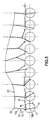
- la figure 5 est un schéma développé montrant les mouvements du piston et des bielles sur un tour de rotation du vilebrequin dans la configuration de montage simple de la figure 3A, et
- la figure 6 est un diagramme analogue à celui de la figure 1 faisant apparaître en outre le cycle de fonctionnement d'une machine à froid agencée conformément à l'invention.
- FIG. 1 is a volume (abscissa) / pressure (ordinate) diagram giving the representation of the theoretical Stirling cycle and the cycle of a conventional cold machine,
- FIG. 2 is a very diagrammatic representation of a conventional cold type machine of the integral type operating according to the Stirling cycle,
- FIGS. 3A to 3D are very schematic views of respectively several alternative embodiments of the arrangement proposed by the invention,
- FIGS. 4A and 4B are representations respectively of two exemplary embodiments of cold type of integral arranged in accordance with the invention,
- Fig. 5 is an expanded diagram showing the movements of the piston and connecting rods on a crankshaft turn in the simple mounting configuration of Fig. 3A, and
- Figure 6 is a diagram similar to that of Figure 1 showing further the operating cycle of a cold machine arranged according to the invention.
Conformément à l'invention, on prévoit que la bielle ou que l'une au moins des bielles de la machine à froid soit agencée avec une longueur variable au cours d'une rotation du vilebrequin de manière que le mouvement du piston correspondant soit au moins ralenti, voire arrêté, au passage du point mort haut et/ou bas, de préférence aux deux, de manière que le cycle de fonctionnement de la machine se rapproche mieux du cycle théorique de Stirling que celui des machines à froid à bielle rigide réalisées jusqu'à présent.According to the invention, it is expected that the rod or at least one of the rods of the cold machine is arranged with a variable length during a rotation of the crankshaft so that the movement of the corresponding piston is at least idle, or even stopped, at the passage of the top and / or bottom dead center, preferably to both, so that the cycle of operation of the machine is closer to the theoretical Stirling cycle than that of the cold rod machines made up to 'now.
Diverses solutions techniques peuvent être envisagées à cet effet.Various technical solutions can be envisaged for this purpose.
La solution qui paraît être la mieux appropriée pour aboutir à un compromis satisfaisant en terme de simplicité structurelle et en terme de qualité du résultat obtenu consiste, comme illustré aux figures 3A à 3D, en ce que la bielle à longueur variable (on supposera à titre d'exemple dans ce qui suit qu'il s'agit de la bielle de compression 12), que l'on désignera dans ce qui suit par le terme de bielle principale, soit formée d'au moins deux tronçons de bielle 12a, 12b articulés l'un à l'autre en 15 et en ce qu'au moins une bielle auxiliaire 16 possède une première extrémité accouplée à rotation en 17 à la bielle principale 12 et une seconde extrémité accouplée à rotation en 18 sur un élément de structure 19 de la machine. Les caractéristiques de l'agencement - notamment longueurs des tronçons de bielle 12a, 12b, emplacements des articulations 15 et 17, longueur de la bielle auxiliaire 16, agencements de l'articulation 18 et de l'élément de structure 19 de la machine - sont déterminés en fonction du résultat souhaité.The solution that seems to be the most appropriate for achieving a satisfactory compromise in terms of structural simplicity and in terms of the quality of the result obtained consists, as illustrated in FIGS. 3A to 3D, in that the variable length connecting rod (it will be assumed that example in the following that it is the compression rod 12), which will be referred to in the following by the term of main rod, is formed of at least two connecting
Diverses variantes de réalisations pratiques peuvent être envisagées.Various variants of practical embodiments can be envisaged.
La variante de réalisation illustrée à la figure 3A est la plus simple du point de vue structurel. L'articulation 15 réunissant les deux tronçons 12a, 12b de bielle et l'articulation 17 réunissant la bielle auxiliaire 16 à la bielle principale 12 sont confondues.The embodiment variant illustrated in FIG. 3A is the simplest from the structural point of view. The joint 15 joining the two
Dans la variante de réalisation montrée à la figure 3B, les deux articulations 15 et 17 sont distinctes et l'articulation 17 est reportée sur l'un des tronçons de bielle, par exemple sur le tronçon de bielle 12a accouplé au piston comme illustré à la figure 3B. La position de l'articulation 17 sur le tronçon de bielle est choisie de manière à définir le bras de levier approprié pour obtenir le mouvement souhaité du piston 6.In the variant embodiment shown in FIG. 3B, the two
Bien entendu, si besoin en est, la bielle principale 12 peut être constituée d'un plus grand nombre de tronçons. La variante de réalisation de la figure 3C met en oeuvre une bielle principale décomposée en trois tronçons de bielle 12a, 12b, 12c réunis par des articulations 15a, 15b ; deux bielles auxiliaires 16a, 16b sont interposées respectivement entre les articulations 15a, 15b et un élément de structure 19 de la machine ; les deux bielles auxiliaires 16a, 16b peuvent être réunies à l'élément de structure 19 par une articulation 18 commune ou bien par deux articulations respectives 18a, 18b distinctes comme illustré à la figure 3C.Of course, if need be, the
Pour ce qui est de l'élément de structure 19 de la machine sur lequel est articulée la bielle auxiliaire 16, il peut s'agir, de façon simple, d'un élément fixe de la structure de la machine, comme cela est illustré aux figures 3A, 3B et 3C. Toutefois, on peut également envisager que l'articulation 18 soit portée par un élément de structure qui soit déplaçable de façon contrôlée de manière que l'articulation 17 soit animée d'une composante de mouvement additionnelle permettant de commander de façon plus fine le mouvement du piston 6. Comme montré à la figure 3D (sur laquelle on a repris la variante la plus simple de la figure 3A), l'élément de structure 19 peut être animé, sous l'action de moyens de commande (non montrés) d'un mouvement sensiblement linéaire (flèche 20), ou bien curviligne, notamment sensiblement en arc de cercle ou circulaire (flèche 21), ou bien selon toute trajectoire appropriée. Dans le cas où plusieurs bielles auxiliaires sont mises en oeuvre, on peut envisager, pour ce qui est de l'élément de structure 19, non seulement les dispositions évoquées ci-dessus (éléments fixes ou déplaçables), mais aussi une combinaison de ces dispositions (éléments de structure fixes pour certaines bielles auxiliaires et déplaçables pour d'autres).As regards the
Pour fixer les idées, on a représenté de façon très schématisée, à la figure 5, le déplacement du piston dans la configuration structurelle la plus simple de l'agencement de la figure 3A. Sur cette figure, seule est représentée l'articulation 22 du tronçon de bielle 12a avec le piston 6, tandis que le piston lui-même n'est pas montré par souci de clarté de lecture du dessin. On constate clairement que l'articulation 22 est animée d'un mouvement (décomposé sur la trajectoire 23) qui, sur un tour de rotation du vilebrequin 11, n'est plus symétrique ni sinusoïdal, mais qui devient asymétrique entre montée et descente et qui est aplati (ralentissement du piston) vers les points morts haut et bas et plus abrupt (accélération du piston) dans les transitions entre les points morts haut et bas.To fix the ideas, it is shown very schematically in Figure 5, the displacement of the piston in the simplest structural configuration of the arrangement of Figure 3A. In this figure, only the
Les dispositions conformes à l'invention se révèlent d'autant plus intéressantes qu'elles peuvent trouver application dans les deux types de machines à froid fonctionnant selon le cycle de Stirling.The provisions according to the invention are all the more interesting that they can find application in both types of cold machines operating according to the Stirling cycle.
Dans les machines du type intégral, les bielles 12 et 13 respectivement des deux pistons de compression 6 et de régénération 9 peuvent être agencées avec des longueurs respectives variables comme illustré à la figure 4A. Pour le compresseur 5, on peut reprendre par exemple l'agencement de la figure 3A, avec la bielle 12 formée de deux tronçons 12a, 12b et avec la bielle auxiliaire 16. Pour le régénérateur 8, on peut prendre un agencement analogue, avec la bielle 13 formée de deux tronçons 13a, 13b et avec une bielle auxiliaire 24.In machines of the integral type, the
Toutefois si l'agencement conformément à l'invention des deux bielles de compression 12 et de régénération 13 est jugé trop complexe et/ou trop coûteux, seule l'une de ces bielles pourra être équipée selon l'invention. De préférence dans ce cas, il est plus avantageux que ce soit la bielle de régénération 13 qui soit agencée avec une longueur variable comme montré à la figure 4B, eu égard au fait que les efforts s'appliquant sur le piston de régénération sont plus faibles que ceux s'appliquant sur le piston de compression.However, if the arrangement according to the invention of the two
Dans les machines du type « splitté », c'est la bielle du piston de compression qui est agencée avec une longueur variable.In machines of the "split" type, it is the connecting rod of the compression piston which is arranged with a variable length.
En définitive, la mise en oeuvre des dispositions conformes à l'invention permet de modifier le cycle de fonctionnement de la machine à froid et, par comparaison avec le cycle B d'une machine classique, de rapprocher ce cycle du cycle théorique de Stirling A dans au moins certaines des régions des points sommitaux 1, 2, 3, 4. Le diagramme de la figure 6 est analogue à celui de la figure 1 et montre à nouveau le cycle théorique de Stirling en A et le cycle B d'une machine classique en tirets, tandis qu'on a ajouté en trait plein le cycle C d'une machine à froid modifiée selon l'invention de manière à améliorer le cycle dans les régions des deux points sommitaux 2 et 4 par ralentissement du mouvement du piston de régénération au voisinage des points morts haut et bas. L'équipement du piston de compression selon l'invention permettrait de la même manière d'améliorer le cycle dans les régions des deux points sommitaux 1 et 3.Ultimately, the implementation of the provisions according to the invention makes it possible to modify the cycle of operation of the cold machine and, by comparison with the cycle B of a conventional machine, to bring this cycle closer to the theoretical Stirling A cycle. in at least some of the regions of the
Claims (10)
ce grâce à quoi le cycle de fonctionnement de la machine se rapproche mieux du cycle théorique de Stirling que celui des machines à froid à bielle rigide réalisées jusqu'à présent.Cold machine operating according to the Stirling cycle and comprising
This is why the machine's operating cycle is closer to the Stirling theoretical cycle than the rigid link chilling machines it has done so far.
Applications Claiming Priority (1)
| Application Number | Priority Date | Filing Date | Title |
|---|---|---|---|
| FR0501100A FR2881513B1 (en) | 2005-02-03 | 2005-02-03 | COLD MACHINE OPERATING FOLLOWING THE STIRLING CYCLE |
Publications (2)
| Publication Number | Publication Date |
|---|---|
| EP1701113A1 true EP1701113A1 (en) | 2006-09-13 |
| EP1701113B1 EP1701113B1 (en) | 2009-10-21 |
Family
ID=35447696
Family Applications (1)
| Application Number | Title | Priority Date | Filing Date |
|---|---|---|---|
| EP06290168A Active EP1701113B1 (en) | 2005-02-03 | 2006-01-27 | Refrigerating machine operating according to the Stirling cycle |
Country Status (6)
| Country | Link |
|---|---|
| US (1) | US7497085B2 (en) |
| EP (1) | EP1701113B1 (en) |
| AT (1) | ATE446488T1 (en) |
| DE (1) | DE602006009858D1 (en) |
| FR (1) | FR2881513B1 (en) |
| IL (1) | IL173495A (en) |
Families Citing this family (2)
| Publication number | Priority date | Publication date | Assignee | Title |
|---|---|---|---|---|
| US20110225987A1 (en) * | 2010-03-21 | 2011-09-22 | Boyd Bowdish | Self generating power generator for cryogenic systems |
| CN102383929B (en) * | 2010-09-01 | 2013-07-24 | 中国航空工业集团公司沈阳飞机设计研究所 | Piston combustion engine with variable bent axle radius |
Citations (6)
| Publication number | Priority date | Publication date | Assignee | Title |
|---|---|---|---|---|
| FR2084109A5 (en) * | 1970-03-02 | 1971-12-17 | Knoeoes Stellan | Gas expansion plant - external combustion engine or heat pump on practically reversible operating cycle |
| US4206609A (en) * | 1978-09-01 | 1980-06-10 | Actus, Inc. | Cryogenic surgical apparatus and method |
| JPH08219569A (en) * | 1995-02-10 | 1996-08-30 | Naoji Isshiki | Variable phase apparatus |
| JPH1019406A (en) * | 1996-06-27 | 1998-01-23 | Sanyo Electric Co Ltd | Gas compression/expansion apparatus |
| JPH1163704A (en) * | 1997-08-27 | 1999-03-05 | Sanyo Electric Co Ltd | Differential pressure controller of piston type compressor |
| BE1011918A3 (en) * | 1998-05-15 | 2000-03-07 | Belge De Construction Et D Eng | Heat conversion method and installation for embodiment of same |
Family Cites Families (12)
| Publication number | Priority date | Publication date | Assignee | Title |
|---|---|---|---|---|
| US3431788A (en) * | 1967-03-01 | 1969-03-11 | Philips Corp | Piston rod guide for rhombic drive stirling cycle apparatus |
| US3845624A (en) * | 1970-05-21 | 1974-11-05 | W Roos | Sterling process engines |
| US4365982A (en) * | 1981-12-30 | 1982-12-28 | The United States Of America As Represented By The Secretary Of The Army | Cryogenic refrigerator |
| IL91281A (en) * | 1989-08-11 | 1994-02-27 | Shirat Enterprises Ltd Tel Avi | Method and apparatus for cooling and scanning infrared detector assemblies |
| GB9008522D0 (en) * | 1990-04-17 | 1990-06-13 | Energy For Suitable Dev Limite | Reciprocatory displacement machine |
| US5136987A (en) * | 1991-06-24 | 1992-08-11 | Ford Motor Company | Variable displacement and compression ratio piston engine |
| JP2000136250A (en) * | 1998-10-29 | 2000-05-16 | Rhein Chem Rheinau Gmbh | Use of arylguanidinium xanthate as vulcanization accelerator, and its production |
| JP4038959B2 (en) * | 2000-05-09 | 2008-01-30 | 日産自動車株式会社 | Variable compression ratio mechanism of internal combustion engine |
| AT411844B (en) * | 2000-05-29 | 2004-06-25 | Kocsisek Karl | HOT GAS ENGINE |
| JP3861583B2 (en) * | 2000-08-14 | 2006-12-20 | 日産自動車株式会社 | Piston crank mechanism of internal combustion engine |
| TW565652B (en) * | 2002-12-13 | 2003-12-11 | Ind Tech Res Inst | Stirling engine with variable stroke |
| JP3783705B2 (en) * | 2003-10-01 | 2006-06-07 | トヨタ自動車株式会社 | Stirling engine and hybrid system using the same |
-
2005
- 2005-02-03 FR FR0501100A patent/FR2881513B1/en not_active Expired - Fee Related
-
2006
- 2006-01-27 DE DE602006009858T patent/DE602006009858D1/en active Active
- 2006-01-27 AT AT06290168T patent/ATE446488T1/en not_active IP Right Cessation
- 2006-01-27 EP EP06290168A patent/EP1701113B1/en active Active
- 2006-02-02 US US11/346,601 patent/US7497085B2/en active Active
- 2006-02-02 IL IL173495A patent/IL173495A/en active IP Right Grant
Patent Citations (6)
| Publication number | Priority date | Publication date | Assignee | Title |
|---|---|---|---|---|
| FR2084109A5 (en) * | 1970-03-02 | 1971-12-17 | Knoeoes Stellan | Gas expansion plant - external combustion engine or heat pump on practically reversible operating cycle |
| US4206609A (en) * | 1978-09-01 | 1980-06-10 | Actus, Inc. | Cryogenic surgical apparatus and method |
| JPH08219569A (en) * | 1995-02-10 | 1996-08-30 | Naoji Isshiki | Variable phase apparatus |
| JPH1019406A (en) * | 1996-06-27 | 1998-01-23 | Sanyo Electric Co Ltd | Gas compression/expansion apparatus |
| JPH1163704A (en) * | 1997-08-27 | 1999-03-05 | Sanyo Electric Co Ltd | Differential pressure controller of piston type compressor |
| BE1011918A3 (en) * | 1998-05-15 | 2000-03-07 | Belge De Construction Et D Eng | Heat conversion method and installation for embodiment of same |
Non-Patent Citations (3)
| Title |
|---|
| PATENT ABSTRACTS OF JAPAN vol. 1996, no. 12 26 December 1996 (1996-12-26) * |
| PATENT ABSTRACTS OF JAPAN vol. 1998, no. 05 30 April 1998 (1998-04-30) * |
| PATENT ABSTRACTS OF JAPAN vol. 1999, no. 08 30 June 1999 (1999-06-30) * |
Also Published As
| Publication number | Publication date |
|---|---|
| ATE446488T1 (en) | 2009-11-15 |
| US20060179850A1 (en) | 2006-08-17 |
| FR2881513A1 (en) | 2006-08-04 |
| US7497085B2 (en) | 2009-03-03 |
| FR2881513B1 (en) | 2007-04-06 |
| IL173495A0 (en) | 2006-06-11 |
| DE602006009858D1 (en) | 2009-12-03 |
| IL173495A (en) | 2010-11-30 |
| EP1701113B1 (en) | 2009-10-21 |
Similar Documents
| Publication | Publication Date | Title |
|---|---|---|
| EP2064431B1 (en) | Heat engine with external hot source | |
| WO2015200432A1 (en) | Variable compression connecting rod | |
| WO1999063206A1 (en) | Operating method and device for supplementary compressed air injection engine operating with mono-energy or bi-energy in two or three powering modes | |
| FR2927137A1 (en) | Movement converting device for piston heat engine, has complementary units cooperated for ensuring deceleration of translation movement of transmission element to define stop position and to start inverse translation movement of element | |
| EP1023531B1 (en) | Method for controlling machine piston movement, implementing device and balancing of said device | |
| EP1701113B1 (en) | Refrigerating machine operating according to the Stirling cycle | |
| FR2928693A1 (en) | INTERNAL COMBUSTION ENGINE | |
| FR2986558A1 (en) | DEVICE FOR VARIABLY CONTROLLING AT LEAST ONE VALVE, FOR EXAMPLE FOR AN ALTERNATIVE ENGINE | |
| WO1981003200A1 (en) | Power amplifier for thermal motors or the like | |
| WO2014140497A1 (en) | Method for controlling the progress of an operating cycle of an internal combustion engine with an extended expansion phase | |
| FR2708970A1 (en) | Internal combustion engine with at least two opposite cylinders. | |
| FR3079877A1 (en) | HOT AIR ENGINE WORKING PERMANENT ACCORDING TO CYCLE DERIVED FROM STIRLING CYCLE | |
| FR2599084A1 (en) | Internal combustion engine without connecting rods or crankshaft of the type having the cylinders in a star formation | |
| WO2016146572A1 (en) | Stirling cooler with fluid transfer by deformable conduit | |
| FR2741909A1 (en) | Heat engine with high yield from energy storage system | |
| FR3006735A1 (en) | MOVEMENT TRANSFORMATION DEVICE AND CORRESPONDING METHOD | |
| FR3021357A1 (en) | INTERNAL COMBUSTION ENGINE WITH OPTIMIZED VOLUME LAW | |
| FR3093543A1 (en) | Hybrid thermodynamic compressor | |
| FR2803874A1 (en) | Reciprocating internal combustion engine with moving cylinder and simple inlet and exhaust ports, uses opposing pistons in sleeve that moves between inlet and exhaust ports | |
| FR2674285A1 (en) | Piston/crank shaft action reverser | |
| WO2020053642A1 (en) | Internal combustion engine having a planetary gear set and reciprocating pistons | |
| BE480388A (en) | ||
| FR3096425A1 (en) | Balancing method of an internal combustion engine | |
| BE507845A (en) | ||
| WO2015036810A1 (en) | Internal combustion engine with a lever system, connecting-rod/crank systems with multiple cranks and a variable compression rate |
Legal Events
| Date | Code | Title | Description |
|---|---|---|---|
| PUAI | Public reference made under article 153(3) epc to a published international application that has entered the european phase |
Free format text: ORIGINAL CODE: 0009012 |
|
| AK | Designated contracting states |
Kind code of ref document: A1 Designated state(s): AT BE BG CH CY CZ DE DK EE ES FI FR GB GR HU IE IS IT LI LT LU LV MC NL PL PT RO SE SI SK TR |
|
| AX | Request for extension of the european patent |
Extension state: AL BA HR MK YU |
|
| 17P | Request for examination filed |
Effective date: 20060923 |
|
| AKX | Designation fees paid |
Designated state(s): AT BE BG CH CY CZ DE DK EE ES FI FR GB GR HU IE IS IT LI LT LU LV MC NL PL PT RO SE SI SK TR |
|
| GRAP | Despatch of communication of intention to grant a patent |
Free format text: ORIGINAL CODE: EPIDOSNIGR1 |
|
| GRAS | Grant fee paid |
Free format text: ORIGINAL CODE: EPIDOSNIGR3 |
|
| GRAA | (expected) grant |
Free format text: ORIGINAL CODE: 0009210 |
|
| AK | Designated contracting states |
Kind code of ref document: B1 Designated state(s): AT BE BG CH CY CZ DE DK EE ES FI FR GB GR HU IE IS IT LI LT LU LV MC NL PL PT RO SE SI SK TR |
|
| REG | Reference to a national code |
Ref country code: GB Ref legal event code: FG4D Free format text: NOT ENGLISH |
|
| REG | Reference to a national code |
Ref country code: CH Ref legal event code: EP |
|
| REG | Reference to a national code |
Ref country code: IE Ref legal event code: FG4D |
|
| REF | Corresponds to: |
Ref document number: 602006009858 Country of ref document: DE Date of ref document: 20091203 Kind code of ref document: P |
|
| LTIE | Lt: invalidation of european patent or patent extension |
Effective date: 20091021 |
|
| PG25 | Lapsed in a contracting state [announced via postgrant information from national office to epo] |
Ref country code: SE Free format text: LAPSE BECAUSE OF FAILURE TO SUBMIT A TRANSLATION OF THE DESCRIPTION OR TO PAY THE FEE WITHIN THE PRESCRIBED TIME-LIMIT Effective date: 20091021 Ref country code: PT Free format text: LAPSE BECAUSE OF FAILURE TO SUBMIT A TRANSLATION OF THE DESCRIPTION OR TO PAY THE FEE WITHIN THE PRESCRIBED TIME-LIMIT Effective date: 20100222 Ref country code: LT Free format text: LAPSE BECAUSE OF FAILURE TO SUBMIT A TRANSLATION OF THE DESCRIPTION OR TO PAY THE FEE WITHIN THE PRESCRIBED TIME-LIMIT Effective date: 20091021 Ref country code: IS Free format text: LAPSE BECAUSE OF FAILURE TO SUBMIT A TRANSLATION OF THE DESCRIPTION OR TO PAY THE FEE WITHIN THE PRESCRIBED TIME-LIMIT Effective date: 20100221 Ref country code: FI Free format text: LAPSE BECAUSE OF FAILURE TO SUBMIT A TRANSLATION OF THE DESCRIPTION OR TO PAY THE FEE WITHIN THE PRESCRIBED TIME-LIMIT Effective date: 20091021 Ref country code: ES Free format text: LAPSE BECAUSE OF FAILURE TO SUBMIT A TRANSLATION OF THE DESCRIPTION OR TO PAY THE FEE WITHIN THE PRESCRIBED TIME-LIMIT Effective date: 20100201 |
|
| REG | Reference to a national code |
Ref country code: IE Ref legal event code: FD4D |
|
| PG25 | Lapsed in a contracting state [announced via postgrant information from national office to epo] |
Ref country code: SI Free format text: LAPSE BECAUSE OF FAILURE TO SUBMIT A TRANSLATION OF THE DESCRIPTION OR TO PAY THE FEE WITHIN THE PRESCRIBED TIME-LIMIT Effective date: 20091021 Ref country code: PL Free format text: LAPSE BECAUSE OF FAILURE TO SUBMIT A TRANSLATION OF THE DESCRIPTION OR TO PAY THE FEE WITHIN THE PRESCRIBED TIME-LIMIT Effective date: 20091021 Ref country code: LV Free format text: LAPSE BECAUSE OF FAILURE TO SUBMIT A TRANSLATION OF THE DESCRIPTION OR TO PAY THE FEE WITHIN THE PRESCRIBED TIME-LIMIT Effective date: 20091021 |
|
| PG25 | Lapsed in a contracting state [announced via postgrant information from national office to epo] |
Ref country code: AT Free format text: LAPSE BECAUSE OF FAILURE TO SUBMIT A TRANSLATION OF THE DESCRIPTION OR TO PAY THE FEE WITHIN THE PRESCRIBED TIME-LIMIT Effective date: 20091021 |
|
| PG25 | Lapsed in a contracting state [announced via postgrant information from national office to epo] |
Ref country code: RO Free format text: LAPSE BECAUSE OF FAILURE TO SUBMIT A TRANSLATION OF THE DESCRIPTION OR TO PAY THE FEE WITHIN THE PRESCRIBED TIME-LIMIT Effective date: 20091021 Ref country code: IE Free format text: LAPSE BECAUSE OF FAILURE TO SUBMIT A TRANSLATION OF THE DESCRIPTION OR TO PAY THE FEE WITHIN THE PRESCRIBED TIME-LIMIT Effective date: 20091021 Ref country code: EE Free format text: LAPSE BECAUSE OF FAILURE TO SUBMIT A TRANSLATION OF THE DESCRIPTION OR TO PAY THE FEE WITHIN THE PRESCRIBED TIME-LIMIT Effective date: 20091021 Ref country code: DK Free format text: LAPSE BECAUSE OF FAILURE TO SUBMIT A TRANSLATION OF THE DESCRIPTION OR TO PAY THE FEE WITHIN THE PRESCRIBED TIME-LIMIT Effective date: 20091021 Ref country code: BG Free format text: LAPSE BECAUSE OF FAILURE TO SUBMIT A TRANSLATION OF THE DESCRIPTION OR TO PAY THE FEE WITHIN THE PRESCRIBED TIME-LIMIT Effective date: 20100121 |
|
| BERE | Be: lapsed |
Owner name: SAGEM DEFENSE SECURITE Effective date: 20100131 |
|
| PLBE | No opposition filed within time limit |
Free format text: ORIGINAL CODE: 0009261 |
|
| STAA | Information on the status of an ep patent application or granted ep patent |
Free format text: STATUS: NO OPPOSITION FILED WITHIN TIME LIMIT |
|
| PG25 | Lapsed in a contracting state [announced via postgrant information from national office to epo] |
Ref country code: SK Free format text: LAPSE BECAUSE OF FAILURE TO SUBMIT A TRANSLATION OF THE DESCRIPTION OR TO PAY THE FEE WITHIN THE PRESCRIBED TIME-LIMIT Effective date: 20091021 Ref country code: MC Free format text: LAPSE BECAUSE OF NON-PAYMENT OF DUE FEES Effective date: 20100131 Ref country code: CZ Free format text: LAPSE BECAUSE OF FAILURE TO SUBMIT A TRANSLATION OF THE DESCRIPTION OR TO PAY THE FEE WITHIN THE PRESCRIBED TIME-LIMIT Effective date: 20091021 |
|
| REG | Reference to a national code |
Ref country code: CH Ref legal event code: PL |
|
| 26N | No opposition filed |
Effective date: 20100722 |
|
| PG25 | Lapsed in a contracting state [announced via postgrant information from national office to epo] |
Ref country code: LI Free format text: LAPSE BECAUSE OF NON-PAYMENT OF DUE FEES Effective date: 20100131 Ref country code: GR Free format text: LAPSE BECAUSE OF FAILURE TO SUBMIT A TRANSLATION OF THE DESCRIPTION OR TO PAY THE FEE WITHIN THE PRESCRIBED TIME-LIMIT Effective date: 20100122 Ref country code: CH Free format text: LAPSE BECAUSE OF NON-PAYMENT OF DUE FEES Effective date: 20100131 |
|
| PG25 | Lapsed in a contracting state [announced via postgrant information from national office to epo] |
Ref country code: BE Free format text: LAPSE BECAUSE OF NON-PAYMENT OF DUE FEES Effective date: 20100131 |
|
| PG25 | Lapsed in a contracting state [announced via postgrant information from national office to epo] |
Ref country code: IT Free format text: LAPSE BECAUSE OF FAILURE TO SUBMIT A TRANSLATION OF THE DESCRIPTION OR TO PAY THE FEE WITHIN THE PRESCRIBED TIME-LIMIT Effective date: 20091021 |
|
| PG25 | Lapsed in a contracting state [announced via postgrant information from national office to epo] |
Ref country code: CY Free format text: LAPSE BECAUSE OF FAILURE TO SUBMIT A TRANSLATION OF THE DESCRIPTION OR TO PAY THE FEE WITHIN THE PRESCRIBED TIME-LIMIT Effective date: 20091021 |
|
| PG25 | Lapsed in a contracting state [announced via postgrant information from national office to epo] |
Ref country code: LU Free format text: LAPSE BECAUSE OF NON-PAYMENT OF DUE FEES Effective date: 20100127 Ref country code: HU Free format text: LAPSE BECAUSE OF FAILURE TO SUBMIT A TRANSLATION OF THE DESCRIPTION OR TO PAY THE FEE WITHIN THE PRESCRIBED TIME-LIMIT Effective date: 20100422 |
|
| PG25 | Lapsed in a contracting state [announced via postgrant information from national office to epo] |
Ref country code: TR Free format text: LAPSE BECAUSE OF FAILURE TO SUBMIT A TRANSLATION OF THE DESCRIPTION OR TO PAY THE FEE WITHIN THE PRESCRIBED TIME-LIMIT Effective date: 20091021 |
|
| REG | Reference to a national code |
Ref country code: FR Ref legal event code: CA Effective date: 20140805 |
|
| REG | Reference to a national code |
Ref country code: FR Ref legal event code: PLFP Year of fee payment: 10 |
|
| REG | Reference to a national code |
Ref country code: FR Ref legal event code: PLFP Year of fee payment: 11 |
|
| REG | Reference to a national code |
Ref country code: FR Ref legal event code: PLFP Year of fee payment: 12 |
|
| REG | Reference to a national code |
Ref country code: FR Ref legal event code: CD Owner name: SAGEM DEFENSE SECURITE, FR Effective date: 20170126 |
|
| REG | Reference to a national code |
Ref country code: FR Ref legal event code: PLFP Year of fee payment: 13 |
|
| PGFP | Annual fee paid to national office [announced via postgrant information from national office to epo] |
Ref country code: NL Payment date: 20191227 Year of fee payment: 15 |
|
| PGFP | Annual fee paid to national office [announced via postgrant information from national office to epo] |
Ref country code: GB Payment date: 20191223 Year of fee payment: 15 Ref country code: DE Payment date: 20191218 Year of fee payment: 15 |
|
| REG | Reference to a national code |
Ref country code: DE Ref legal event code: R119 Ref document number: 602006009858 Country of ref document: DE |
|
| REG | Reference to a national code |
Ref country code: NL Ref legal event code: MM Effective date: 20210201 |
|
| GBPC | Gb: european patent ceased through non-payment of renewal fee |
Effective date: 20210127 |
|
| PG25 | Lapsed in a contracting state [announced via postgrant information from national office to epo] |
Ref country code: NL Free format text: LAPSE BECAUSE OF NON-PAYMENT OF DUE FEES Effective date: 20210201 |
|
| PG25 | Lapsed in a contracting state [announced via postgrant information from national office to epo] |
Ref country code: DE Free format text: LAPSE BECAUSE OF NON-PAYMENT OF DUE FEES Effective date: 20210803 Ref country code: GB Free format text: LAPSE BECAUSE OF NON-PAYMENT OF DUE FEES Effective date: 20210127 |
|
| PGFP | Annual fee paid to national office [announced via postgrant information from national office to epo] |
Ref country code: FR Payment date: 20231219 Year of fee payment: 19 |