EP1705687A1 - Method of Arc Detection - Google Patents
Method of Arc Detection Download PDFInfo
- Publication number
- EP1705687A1 EP1705687A1 EP05006680A EP05006680A EP1705687A1 EP 1705687 A1 EP1705687 A1 EP 1705687A1 EP 05006680 A EP05006680 A EP 05006680A EP 05006680 A EP05006680 A EP 05006680A EP 1705687 A1 EP1705687 A1 EP 1705687A1
- Authority
- EP
- European Patent Office
- Prior art keywords
- signal
- determined
- output signal
- duration
- wave
- Prior art date
- Legal status (The legal status is an assumption and is not a legal conclusion. Google has not performed a legal analysis and makes no representation as to the accuracy of the status listed.)
- Granted
Links
Images

Classifications
-
- H—ELECTRICITY
- H01—ELECTRIC ELEMENTS
- H01J—ELECTRIC DISCHARGE TUBES OR DISCHARGE LAMPS
- H01J37/00—Discharge tubes with provision for introducing objects or material to be exposed to the discharge, e.g. for the purpose of examination or processing thereof
- H01J37/32—Gas-filled discharge tubes
- H01J37/32431—Constructional details of the reactor
- H01J37/32623—Mechanical discharge control means
-
- H—ELECTRICITY
- H01—ELECTRIC ELEMENTS
- H01J—ELECTRIC DISCHARGE TUBES OR DISCHARGE LAMPS
- H01J2237/00—Discharge tubes exposing object to beam, e.g. for analysis treatment, etching, imaging
- H01J2237/02—Details
- H01J2237/0203—Protection arrangements
- H01J2237/0206—Extinguishing, preventing or controlling unwanted discharges
Landscapes
- Physics & Mathematics (AREA)
- Engineering & Computer Science (AREA)
- Plasma & Fusion (AREA)
- Chemical & Material Sciences (AREA)
- Analytical Chemistry (AREA)
- Plasma Technology (AREA)
- Analysing Materials By The Use Of Radiation (AREA)
- Investigating, Analyzing Materials By Fluorescence Or Luminescence (AREA)
- Arc Welding Control (AREA)
Abstract
Description
Die Erfindung betrifft ein Verfahren zur Arcerkennung in einem Plasmaprozess, der von einem insbesondere frei schwingenden Wechselstromgenerator mit einem Ausgangssignal des Wechselstromgenerators zur Leistungszufuhr gespeist wird, wobei eine mit dem zeitlichen Verlauf des Ausgangssignals oder eines mit dem Ausgangssignal in Zusammenhang stehenden internen Signals des Wechselstromgenerators in Beziehung stehende Größe gemessen oder ermittelt wirdThe invention relates to a method for arc detection in a plasma process, which is fed by a particular free-swinging alternator with an output signal of the alternator for power supply, one with the timing of the output signal or an output signal related to the internal signal of the alternator in relation standing size is measured or determined
Die Beschichtung von Substraten, z.B. Glasflächen mittels Sputtern/Kathodenzerstäuben in Plasmaprozessen, und zwar sowohl reaktiv als auch konventionell, ist z.B. aus der Architekturglasbeschichtung bekannt. Dazu wird mit einer Strom- oder Spannungsquelle ein Plasma erzeugt, das von einem Target Material abträgt, welches sich auf dem Substrat, z.B. der Glasscheibe, ablagert. Vor der Ablagerung können sich die Atome je nach gewünschter Beschichtung in einem reaktiven Prozess noch mit Gasatomen oder -molekülen verbinden.The coating of substrates, e.g. Glass surfaces by sputtering / sputtering in plasma processes, both reactive and conventional, are e.g. known from the architectural glass coating. For this purpose, a plasma is generated with a current or voltage source, which removes material from a target, which is deposited on the substrate, e.g. the glass pane, deposits. Before deposition, the atoms can still combine with gas atoms or molecules in a reactive process, depending on the desired coating.
Insbesondere bei reaktiven Prozessen werden häufig MF-Generatoren eingesetzt, die üblicherweise bei einer Frequenz von 10 - 500kHz arbeiten. Diese gibt es als so genannte frei schwingende MF-Generatoren oder als MF-Generatoren mit Festfrequenz. Die frei schwingenden MF-Generatoren sind in der Regel wie folgt aufgebaut: Aus einer Ein- oder Mehrphasenspannung des Versorgungsnetzes wird eine geregelte oder ungeregelte Gleichspannung, die Zwischenkreisspannung erzeugt. Die Zwischenkreisspannung wird mit einer Inverterschaltung (z.B. Brückenschaltung) zu einer Mittelfrequenz (MF)-Wechselspannung umgewandelt (10-500kHz). Das MF-Ausgangsleistungssignal wird auf einen Schwingkreis geschaltet, der zu einer Schwingung angeregt wird. Dabei wird der Inverter so betrieben, dass der Schwingkreis in der Nähe der Resonanzfrequenz betrieben wird. Der Schwingkreis kann ein Serienschwingkreis oder ein Parallelschwingkreis sein. Ein Serienschwingkreis wird mit einem Ausgangsleistungssignal mit einer Spannungsquellencharakteristik angeregt, wohingegen der Parallelkreis mit einem Ausgangsleistungssignal mit einer Stromquellencharakteristik angeregt wird. Um aus der Zwischenkreisspannung, die üblicherweise Spannungsquellencharakteristik besitzt, eine Stromquellencharakteristik zu generieren, werden Drosseln mit genügend großer Induktivität in Serie mit dem Inverter geschaltet. Üblicherweise wird die MF-Leistung an der Spule des Schwingkreises ausgekoppelt und an zwei Elektroden in einer Beschichtungskammer einer Beschichtungsanlage angeschlossen, so dass in der Beschichtungskammer ein Plasma erzeugt werden kann. Die Auskopplung kann über einen Ausgangstransformator erfolgen, der für die galvanische Trennung vom Netz sorgt. Die Elektroden arbeiten bei einem MF-Anregungssystem abwechselnd als Anode und Kathode. Die Resonanzfrequenz des Schwingkreises ist abhängig von der Impedanz des Plasmas. Damit der Inverter immer in der Nähe der Resonanzfrequenz betrieben wird, muss die Steuerung für den Inverter die Periodendauer oder die Dauer einer Halbwelle des MF-Ausgangsleistungssignals überwachen. Sie nimmt die Dauer der Periode bzw. der Halbwelle als Maß für die Zeitdauer des nächsten Umschaltens des Inverters. Wenn sich die Dauer der Periode bzw. einer Halbwelle ändert, so ist dies ein Zeichen dafür, dass sich die Plasmaimpedanz geändert hat.Especially in reactive processes MF generators are commonly used, which usually work at a frequency of 10 - 500kHz. These are available as so-called free-swinging MF generators or as MF generators with fixed frequency. The freely oscillating MF generators are usually constructed as follows: From a single or multi-phase voltage of the supply network is a regulated or unregulated DC voltage, the DC link voltage generated. The DC link voltage is converted with an inverter circuit (eg bridge circuit) to a medium frequency (MF) AC voltage (10-500kHz). The MF output power signal is switched to a resonant circuit, which is excited to vibrate. In this case, the inverter is operated so that the resonant circuit is operated in the vicinity of the resonance frequency. The resonant circuit may be a series resonant circuit or a parallel resonant circuit. A series resonant circuit is excited with an output power signal having a voltage source characteristic, whereas the parallel circuit is excited with an output power signal having a current source characteristic. In order to generate a current source characteristic from the intermediate circuit voltage, which usually has voltage source characteristics, inductors with a sufficiently large inductance are connected in series with the inverter. Usually, the MF power is coupled to the coil of the resonant circuit and connected to two electrodes in a coating chamber of a coating system, so that in the coating chamber, a plasma can be generated. The decoupling can be done via an output transformer, which ensures the galvanic isolation from the mains. The electrodes operate alternately as anode and cathode in an MF excitation system. The resonant frequency of the resonant circuit is dependent on the impedance of the plasma. In order for the inverter to always operate near the resonant frequency, the controller for the inverter must monitor the period or duration of a half cycle of the MF output power signal. It takes the duration of the period or half-wave as a measure of the duration of the next switching of the inverter. If the duration of the period or half-wave changes, this is an indication that the plasma impedance has changed.
Dies ist z. B. aus der
Insbesondere bei reaktiven Prozessen kommt es auch bei MF-Generatoren zu Überschlägen, die oft mit der nächsten Spannungsumkehr oder zumindest nach wenigen Perioden von selbst verlöschen, zu so genannten Micro-Arcs. Es können aber auch energiereichere und länger andauernde Arcs auftreten. Bisher wurden alle Arcs erkannt durch Überprüfen der Ausgangsspannung auf einen Spannungseinbruch oder durch Überprüfen des Ausgangsstroms auf einen Stromanstieg. Alternativ kann ein Arc an der Differenz zwischen den Strömen zu den einzelnen Elektroden erkannt werden. Ein Grenzwert für die Erkennung von Arcs kann im Stand der Technik vom Betreiber eingestellt werden. Für die Erkennung werden die effektiven Werte von Strom und Spannung gemessen. Da eine solche Messung die Spannungswerte und Stromwerte über die Periode betragsmäßig aufintegrieren muss, um nicht Nulldurchgänge als Spannungsabsenkungen zu erkennen, ist diese Art der Erkennung eines Arcs in der Regel deutlich langsamer als die Dauer einer Halbwelle der MF - Ausgangsspannung und damit länger als 40µs.Particularly in the case of reactive processes, flashovers often occur with MF generators, which often go out of their own accord with the next voltage reversal or at least after a few periods, becoming so-called micro-arcs. However, more energetic and longer-lasting arcs may also occur. Previously, all arcs were detected by checking the output voltage for a voltage dip or by checking the output current for a current increase. Alternatively, an arc may be detected in the difference between the currents to the individual electrodes. A threshold for the detection of arcs can be set in the prior art by the operator. For detection, the effective values of current and voltage are measured. Since such a measurement must integrate the voltage values and current values over the period so as not to detect zero crossings as voltage drops, this type of detection of an arc is generally significantly slower than the duration of a half wave of the MF output voltage and thus longer than 40 μs.
Bei der Verwendung der MF - Generatoren im Halbleiterfertigungsprozess, insbesondere in der Flat-Panel-Display FPD - Herstellung, werden aber erhöhte Anforderungen an die Generatoren gestellt. Hier sollen Arcs innerhalb weniger µs erkannt werden.However, when using the MF generators in the semiconductor manufacturing process, in particular in the flat-panel display FPD production, increased demands are placed on the generators. Here, arcs should be detected within a few μs.
Aufgabe der vorliegenden Erfindung ist es, ein Verfahren und eine Vorrichtung für eine noch schnellere Arcerkennung bereitzustellen.The object of the present invention is to provide a method and a device for an even faster arc detection.
Diese Aufgabe wird mit einem Verfahren in der eingangs genannten Art dadurch gelöst, dass unter Berücksichtigung des zeitlichen Verlaufs eine Referenzgröße bestimmt wird, die Referenzgröße mit einem Schwellenwert verglichen wird und bei einem vorgegebenen Vergleichsergebnis ein Arc erkannt wird. Während es im Stand der Technik bekannt ist, ein Ausgangssignal zu überwachen und aus der Überwachung auf Plasmaimpedanzänderungen zu schließen und gegebenenfalls den Plasmaprozess anzupassen, ist es mit dem erfindungsgemäßen Verfahren möglich, das Auftreten von Arcs im Plasmaprozess schnell zu erkennen und gegebenenfalls darauf zu reagieren. Als mit dem Ausgangssignal in Beziehung stehendes internes Signal kommt beispielsweise ein Ausgangssignal eines Inverters des Wechselstromgenerators infrage, das auf einen Ausgangsschwingkreis des Wechselstromgenerators gegeben wird. Als mit dem zeitlichen Verlauf in Beziehung stehende Größe kommen beispielsweise die Frequenz, die Periodendauer oder das Frequenzspektrum des Ausgangssignals bzw. des mit dem Ausgangssignal in Beziehung stehenden internen Signals infrage. Mit diesem Verfahren ist eine extrem schnelle Arcerkennung möglich. Insbesondere kann ein Arc innerhalb einer halben Periodendauer, d.h. innerhalb von 40 µs erkannt werden.This object is achieved by a method in the aforementioned type in that, taking into account the time course, a reference variable is determined, the reference variable is compared with a threshold value and an arc is detected for a given comparison result. While it is known in the art to monitor an output signal and to deduce from the monitoring of plasma impedance changes and, if appropriate, to adapt the plasma process, it is possible with the method according to the invention to quickly detect the occurrence of arcs in the plasma process and to react to them if necessary. As an output signal related to the internal signal, for example, an output signal of an inverter of the alternator is in question, which is applied to an output resonant circuit of the alternator. By way of example, the magnitude, the period duration or the frequency spectrum of the output signal or of the internal signal related to the output signal can be considered as the quantity related to the time profile. This method enables extremely fast arc detection. In particular, an arc can within half a period, i. be detected within 40 μs.
Bei einer besonders bevorzugten Verfahrensvariante kann vorgesehen sein, dass bei Erkennen eines Arcs die Leistungszufuhr zum Plasmaprozess unterbrochen wird, insbesondere für eine vorgebbare Zeitspanne unterbrochen wird. Dadurch kann die Restenergie im Ausgangsschwingkreis ausschwingen und werden Arcs nicht zusätzlich mit Energie versorgt. Dies führt zu einem raschen Löschen von Arcs und damit zu geringen Beschädigungen in der Plasmakammer. Die Leistungszufuhr zum Plasmaprozess kann unterbrochen werden, indem die den Eingang eines Inverters des Wechselstromgenerators bildenden Leitungen kurzgeschlossen oder niederohmig verbunden werden. Dies ist möglich, wenn der Strom von einer Zwischenkreisspannung zu einem Inverter begrenzt ist, wie dies beispielsweise bei MF-Generatoren mit Parallelschwingkreis am Ausgang häufig durch Drosseln erreicht wird. Alternativ ist es möglich, dass der Inverter so geschaltet wird, dass der vom Netzteil kommende, zumindest zwei Leitungen unterschiedlichen Potenzials aufweisende Strompfad kurzgeschlossen oder niederohmig verbunden wird.In a particularly preferred variant of the method it can be provided that, when an arc is detected, the power supply to the plasma process is interrupted, in particular interrupted for a predefinable period of time. As a result, the residual energy in the output resonant circuit can swing out and arcs are not additionally supplied with energy. This leads to a rapid erasure of arcs and thus to minor damage in the plasma chamber. The power supply to the plasma process may be interrupted by shorting the lines forming the input of an inverter of the alternator or low impedance connected. This is possible if the current is limited by an intermediate circuit voltage to an inverter, as is frequently achieved by throttling, for example, in MF generators with parallel resonant circuit at the output. Alternatively, it is possible that the inverter is switched so that the current coming from the power supply, at least two lines different potential having current path is short-circuited or connected low impedance.
Besonders vorteilhaft ist es, wenn als mit dem zeitlichen Verlauf des Ausgangssignals oder des internen Signals in Beziehung stehende Größe die Dauer von Halbwellen des Ausgangssignals ermittelt wird. Bei frei schwingenden MF- Wechselstromgeneratoren ist eine Nulldurchgangserkennung der Ausgangsspannung ohnehin realisiert. Die Nulldurchgangserkennung wird für die Steuerung eines Inverters benötigt. Diese Nulldurchgangserkennung kann dazu genutzt werden, Arcs innerhalb der Dauer einer Halbwelle zu erkennen.It is particularly advantageous if the duration of half-waves of the output signal is determined as the quantity related to the time profile of the output signal or of the internal signal. In freely oscillating MF AC generators, a zero-crossing detection of the output voltage is realized anyway. Zero crossing detection is needed to control an inverter. This zero-crossing detection can be used to detect arcs within the duration of a half-wave.
Es ist denkbar, dass die Dauer der Halbwellen ermittelt wird, indem die Nulldurchgänge des Ausgangssignals oder des internen Signals erfasst werden und die zeitliche Differenz zwischen zwei Nulldurchgängen bestimmt wird. Alternativ kann die Dauer der Halbwellen aus der Periode oder der Frequenz des Ausgangssignals ermittelt werden. Weiterhin ist es denkbar, die Zeitdauer zischen zwei Maxima des Ausgangssignals zu ermitteln.
Der Zeitabstand von einem Nulldurchgang zum nächsten Nulldurchgang kann jedoch besonders einfach ermittelt werden. Der Inverter wird passend zum nächsten Nulldurchgang umgepolt, dabei werden Totzeiten der Inverterschaltung berücksichtigt, weshalb das Umpolen des Inverters nach Ablauf einer etwas kürzeren Zeit beginnt, als die Zeit, die für die Dauer der Halbwelle zuvor gemessen wurde. Gleichzeitig wird der tatsächliche Nulldurchgang der Spannung wieder überwacht und die tatsächliche Zeit bis zum Nulldurchgang wieder ermittelt. Bei langsamen Impedanzänderungen ändert sich die Zeitdauer von Nulldurchgang zu Nulldurchgang ebenfalls langsam. Eine plötzliche erhebliche Änderung, vor allem eine Verkürzung der Zeitdauer von einem Nulldurchgang zum nächsten Nulldurchgang, ist ein sicherer Hinweis auf einen Arc im Plasma. Daher ist es besonders vorteilhaft, wenn die Dauer der aktuellen Halbwelle als Referenzgröße bestimmt wird.It is conceivable that the duration of the half-waves is determined by detecting the zero crossings of the output signal or of the internal signal and determining the time difference between two zero crossings. Alternatively, the duration of the halfwaves may be determined from the period or the frequency of the output signal. Furthermore, it is conceivable to determine the duration hiss two maxima of the output signal.
However, the time interval from a zero crossing to the next zero crossing can be determined particularly easily. The inverter is reversed to match the next zero crossing, taking into account dead times of the inverter circuit, which is why the reversal of the inverter begins after a slightly shorter time than the time previously measured for the duration of the half-wave. At the same time, the actual zero crossing of the voltage is monitored again and the actual time until again determined to zero crossing. With slow impedance changes, the time from zero crossing to zero crossing also changes slowly. A sudden significant change, especially a shortening of the time from one zero crossing to the next zero crossing, is a sure indication of an arc in the plasma. Therefore, it is particularly advantageous if the duration of the current half-wave is determined as a reference variable.
Alternativ ist es denkbar, als Referenzgröße die Differenz oder das Verhältnis zweier Halbwellendauern zu bestimmen, insbesondere der aktuellen Halbwellendauer und der vorhergehenden Halbwellendauer. Wenn mehrere Halbwellendauern ermittelt werden, kann auch die Periode ermittelt werden und kann ein auf die Periode normierter Wert als Referenzgröße bestimmt werden.Alternatively, it is conceivable to determine the difference or the ratio of two half-wave durations as reference variable, in particular the current half-wave duration and the preceding half-wave duration. If several half-wave durations are determined, the period can also be determined and a value normalized to the period can be determined as the reference variable.
Um auszuschließen, dass erlaubte Impedanzschwankungen zum Erkennen eines Arcs führen, kann vorgesehen sein, dass bei der Ermittlung der Referenzgröße mehrere Halbwellendauern berücksichtigt werden, insbesondere ein vorzugsweise gewichteter Mittelwert von Halbwellendauern der Vergangenheit berücksichtigt wird.In order to rule out that permissible impedance fluctuations lead to the detection of an arc, it can be provided that several half-wave durations are taken into account when determining the reference variable, in particular taking into account a preferably weighted average of half-wave durations of the past.
Das Verfahren lässt sich besonders einfach und mit geringem Rechenaufwand durchführen, wenn als Schwellenwert eine Größe fest vorgegeben wird.The method can be carried out particularly easily and with little computational effort if a size is specified as the threshold value.
Eine zuverlässigere Arcerkennung ergibt sich jedoch, wenn der Schwellenwert plasmaprozessabhängig bestimmt wird. Somit kann ausgeschlossen werden, dass zulässige Impedanzschwankungen zu einem Erkennen eines Arcs führen und somit der Plasmaprozess unnötig oft unterbrochen wird.However, a more reliable arc detection results if the threshold value is determined as a function of the plasma process. Thus, it can be ruled out that permissible impedance fluctuations lead to recognition of an arc and thus the plasma process is interrupted unnecessarily often.
Eine besonders einfache plasmaprozessabhängige Anpassung des Schwellenwerts ergibt sich, wenn die Periode des Ausgangssignal oder des internen Signals bestimmt wird und der Schwellenwert in Abhängigkeit von der Periode bestimmt wird. Bei einem frei schwingenden Wechselstromgenerator ist die Frequenz und damit die Periode des Ausgangssignals ein Maß für die Impedanz des Plasmaprozesses. Sie ändert sich daher bei einer Änderung der Impedanz und somit beim Auftreten eines Arcs. Dabei kann die letzte ermittelte Periode verwendet werden oder eine aus einer vorgebbaren Anzahl von vorhergehenden Perioden gemittelte Periode verwendet werden. Insbesondere kann die Periode des Ausgangssignals ständig erfasst und aktualisiert werden. Weiterhin ist es denkbar, eine normierte Periode des Ausgangssignals oder des internen Signals zu verwenden. Die Periode kann auch aus einer vorgebbaren Anzahl von erfassten Halbwellendauern ermittelt werden.A particularly simple plasma process-dependent adjustment of the threshold results when the period of the output signal or of the internal signal is determined and the threshold value is determined as a function of the period. In a free-swinging alternator, the frequency and thus the period of the output signal is a measure of the impedance of the plasma process. It therefore changes with a change in impedance and thus when an arc occurs. In this case, the last determined period can be used or a period averaged from a predeterminable number of preceding periods can be used. In particular, the period of the output signal can be constantly detected and updated. Furthermore, it is conceivable to use a normalized period of the output signal or of the internal signal. The period can also be determined from a predefinable number of detected half-wave durations.
Vorrichtungsmäßig betrifft die Erfindung eine Plasmaanregungsanordnung mir einem insbesondere frei schwingenden Wechselstromgenerator, der an einen Plasmaprozess, d.h. Elektroden einer Plasmakammer, anschließbar ist, mit einer Signalüberwachungseinrichtung zur Überwachung des zeitlichen Verlaufs eines Ausgangssignals oder eines internen Signals des Wechselstromgenerators, wobei eine Referenzgrößenermittlungseinrichtung vorgesehen ist, die mit der Signalüberwachungseinrichtung und einem Vergleicher verbunden ist, und eine Schwellwertvorgabeeinrichtung vorgesehen ist, die ebenfalls mit dem Vergleicher verbunden ist, wobei der Vergleicher mit Mitteln zur Erzeugung eines Abschaltsignals, insbesondere des Wechselstromgenerators, verbunden ist oder solche aufweist. Mit einer derartigen Anordnung können Arcs in einem Plasmaprozess schnell erkannt werden und kann die Leistungszufuhr zum Plasmaprozess schnell unterbunden werden. Der zeitliche Verlauf kann insbesondere dadurch überwacht werden, dass die Nulldurchgänge des Ausgangssignals oder des internen Signals erfasst werden. Alternativ kann die Frequenz oder Periodendauer des Ausgangssignals oder des internen Signals überwacht werden. Durch das Abschaltsignal kann die Unterbrechung der Energiezufuhr zur Plasmakammer bewirkt werden.In terms of apparatus, the invention relates to a plasma excitation arrangement with a particular free-swinging alternator, which is connected to a plasma process, ie electrodes of a plasma chamber, with a signal monitoring device for monitoring the time course of an output signal or an internal signal of the alternator, wherein a Referenzgrößenermittlungseinrichtung is provided is connected to the signal monitoring device and a comparator, and a Schwellwertvorgabeeinrichtung is provided, which is also connected to the comparator, wherein the comparator with means for generating a shutdown signal, in particular the AC generator, connected, or has such. With such an arrangement, arcs can be quickly detected in a plasma process, and the power supply to the plasma process can be quickly inhibited. The temporal course can in particular thereby be monitored that the zero crossings of the output signal or the internal signal are detected. Alternatively, the frequency or period of the output signal or the internal signal can be monitored. By the shutdown signal, the interruption of the power supply to the plasma chamber can be effected.
Bei einer bevorzugten Ausführungsform ist eine Steuereinrichtung zur Steuerung des Wechselstromgenerators vorgesehen, wobei die Referenzgrößenermittlungseinrichtung und der Vergleicher in der Steuereinrichtung angeordnet sein können.In a preferred embodiment, a control device is provided for controlling the alternator, wherein the reference quantity determination device and the comparator can be arranged in the control device.
Bei einer vorteilhaften Ausgestaltung der Erfindung sind die Signalüberwachungseinrichtung als Komparatorschaltung und die Referenzgrößenermittlungseinrichtung als Prozessor, insbesondere als digitaler Signalprozessor, ausgebildet.In an advantageous embodiment of the invention, the signal monitoring device as a comparator circuit and the reference size determination device as a processor, in particular as a digital signal processor formed.
Weitere Merkmale und Vorteile der Erfindung ergeben sich aus der nachfolgenden Beschreibung von Ausführungsbeispielen der Erfindung, anhand der Figuren der Zeichnung, die erfindungswesentliche Einzelheiten zeigen, und aus den Ansprüchen. Die einzelnen Merkmale können je einzeln für sich oder zu mehreren in beliebiger Kombination bei einer Variante der Erfindung verwirklicht sein. Bevorzugte Ausführungsbeispiele der Erfindung sind in der Zeichnung schematisch dargestellt und werden nachfolgend mit Bezug zu den Figuren der Zeichnung näher erläutert. Es zeigt:
- Fig. 1
- eine schematische Darstellung einer Plasmaanregungsanordnung;
- Fig. 2a
- eine Darstellung eines Ausgangssignalsverlaufs ohne Auftreten eines Arcs;
- Fig. 2b
- eine Darstellung eines Ausgangssignalverlaufs mit Auftreten eines Arcs;
- Fig. 3
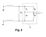
- eine Detaildarstellung eines Inverters der Plasmaanregungsanordnung.
- Fig. 1
- a schematic representation of a plasma excitation arrangement;
- Fig. 2a
- a representation of an output waveform without occurrence of an arc;
- Fig. 2b
- a representation of an output signal waveform with the occurrence of an arc;
- Fig. 3
- a detailed view of an inverter of the plasma excitation arrangement.
In der Fig. 1 ist eine Plasmaanregungsanordnung 1 dargestellt, die über einen Netzanschluss an 2 an eine Mehrphaseneingangsspannung anschließbar ist. Über den Netzanschluss 2 ist eine DC-Stromversorgung 3 an die Mehrphaseneingangsspannung angeschlossen, um an ihrem Ausgang 4 eine Zwischenkreisspannung zu erzeugen. Dazu kann die DC-Stromversorgung 3 einen Netzgleichrichter und einen DC/DC-Wandler aufweisen.1 shows a
Ein als Mittelfrequenz (MF) - Einheit ausgebildeter Wechselstromgenerator 5 wird durch die Zwischenkreisspannung gespeist. Insbesondere ist ein Inverter 6 über Drosseln 7, 8 an die Zwischenkreisspannung angeschlossen. In dem Inverter 6 wird eine Wechselspannung erzeugt Diese Wechselspannung ist als internes Signal am Ausgang des Inverters 6 vorhanden. Eine galvanische Trennung wird durch einen Ausgangsübertrager 10 realisiert, der die Wechselspannung des Inverters 6 in ein Ausgangssignal am Ausgang 11 des Wechselstromgenerators 5 transformiert. Ein Kondensator 9 und die Streuinduktivität des Ausgangsübertragers 10 ergeben einen Parallelresonanzkreis, der einen Ausgangsschwingkreis darstellt. Das Ausgangssignal kann einer nicht dargestellten Plasmakammer zugeführt werden.An
Über Signalüberwachungseinrichtungen 12, 13 können das interne und/oder das Ausgangssignal erfasst werden. Die Signalüberwachungseinrichtungen 12, 13 sind mit einer Steuereinrichtung 14 verbunden. Die Steuereinrichtung 14 umfasst eine Referenzgrößenermittlungseinrichtung 15, um aus dem ermittelten internen Signal oder Ausgangssignal bzw. einem mit dem zeitlichen Verlauf der Signale zusammenhängenden Signal eine Referenzgröße zu ermitteln. Diese Referenzgröße wird in einem Vergleicher 16 mit einem Schwellenwert verglichen, der von einer Schwellenwertvorgabeeinrichtung 17 vorgegeben wird. Der Vergleicher 16 steuert Mittel 18 zur Generierung eines Abschaltsignals in Abhängigkeit von dem Vergleichsergebnis an. Durch das Abschaltsignal kann Unterbrechung der Energiezufuhr zur Plasmakammer bewirkt werden.Via
In der Fig. 2a ist beispielhaft ein Verlauf eines Ausgangssignals 20 des Wechselstromgenerators 5 gezeigt. Durch die Signalüberwachungseinrichtung 13 werden die Nulldurchgänge t1 - t4 detektiert. Beispielsweise generiert ein Komparator in der Signalüberwachungseinrichtung 13 eine Flanke bzw. eine Pegeländerung eines Signals bei jedem Nulldurchgang t1, t2, t3, t4 des überwachten Signals. Der Zeitabstand von einem Nulldurchgang t1 - t4 zum nächsten Nulldurchgang t1 - t4 wird ermittelt. Der Inverter 6 wird passend zum nächsten Nulldurchgang umgepolt, dabei werden Totzeiten der Inverterschaltung berücksichtigt, weshalb das Umpolen des Inverters 6 nach Ablauf einer etwas kürzeren Zeit beginnt, als die Zeitdauer, die für die vorhergehende Halbwelle gemessen wurde (Inverterumpolung z.B. zum Zeitpunkt t21). Gleichzeitig wird der tatsächliche Nulldurchgang t1 - t4 des Ausgangssignals 20, insbesondere der Ausgangsspannung, wieder überwacht und die tatsächliche Zeit bis zum Nulldurchgang t1 - t4 wieder ermittelt. Bei langsamen Impedanzänderungen ändert sich die Zeitdauer von Nulldurchgang t1 - t4 zu Nulldurchgang t1 - t4 ebenfalls langsam. Eine plötzliche erhebliche Änderung, vor allem eine Verkürzung der Zeitdauer von einem Nulldurchgang zum nächsten Nulldurchgang, wie z.B. von t2 zu t31 des Ausgangssignals 21 in Fig. 2b ist ein sicherer Hinweis für das Auftreten eines Arcs im Plasma. Der Schwellenwert, ab dem ein Arc erkannt werden soll, kann eingestellt werden bzw. durch die Schwellenwertvorgabeeinrichtung 17 vorgegeben werden.In FIG. 2 a, a profile of an
Aus dem Vorstehenden ergibt sich, dass die gemessene Dauer einer Halbwelle als Referenzgröße verwendet werden kann, die mit einem Schwellenwert verglichen wird. Alternativ kann die Differenz Δt = (t3-t2) - (t2-t1) (Fig. 2a) bzw. Δt = (t31-t2) - (t2-t1) (Fig. 2b) berechnet werden. Wenn diese Differenz um mehr als einen vorgegebenen Schwellenwert von 0 abweicht (Fig. 2b), deutet dies auf das Vorhandensein eines Arcs im Plasma hin.It follows from the above that the measured duration of a half wave can be used as a reference, which is compared with a threshold value. Alternatively, the difference Δt = (t3-t2) - (t2-t1) (Fig. 2a) and Δt = (t31-t2) - (t2-t1) (Fig. 2b) can be calculated. If this difference deviates by more than a predetermined threshold of 0 (Figure 2b), this indicates the presence of an arc in the plasma.
Die Referenzgrößen können auch auf die Periodendauer T normiert werden. Dabei kann die Periodendauer T ständig berechnet werden, damit 'erlaubte' Impedanzschwankungen nicht zum Erkennen eines Arcs führen.The reference variables can also be normalized to the period T. In this case, the period T can be calculated continuously so that 'allowed' impedance fluctuations do not lead to the detection of an arc.
Da Nulldurchgänge mit einer Komparatorschaltung sehr einfach digital erkannt werden können und Flanken von Mikro-Prozessoren, z.B. digitalen Signalprozessoren sehr leicht und schnell ausgewertet werden können, ist eine digitale Steuereinrichtung 17 in Verbindung mit der Arcerkennung vorteilhaft.Since zero crossings can easily be digitally detected with a comparator circuit and flanks of micro-processors, e.g. digital signal processors can be evaluated very easily and quickly, a
In der Fig. 3 ist eine Detaildarstellung eines Inverters 6 gezeigt. Der Inverter 6 weist eine Vollbrücke auf, die aus vier als Transistoren ausgebildeten schaltenden Elementen T1 - T4 besteht. Diese schaltenden Elemente T1 - T4 werden durch die Steuereinrichtung 14 angesteuert. Zur Unterbrechung der Leistungszufuhr in die Plasmakammer sind verschiedene Szenarien denkbar. Zum einen ist es denkbar, die schaltenden Elemente T1 und T3 leitend zu schalten, um den Strom von der DC-Stromversorgung 3 kurzzuschließen bzw. die Klemmen 30, 31 kurz zu schließen oder niederohmig zu verbinden.FIG. 3 shows a detailed representation of an
Zum anderen ist es denkbar, die schaltenden Elemente T2 und T4 für den gleichen Effekt durchzuschalten.On the other hand, it is conceivable to turn on the switching elements T2 and T4 for the same effect.
Werden die schaltenden Elemente T1, T2 oder T3, T4 oder alle schaltenden Elemente T1 - T4 so angesteuert, dass sie leitend sind, wird der Ausgangsschwingkreis, bestehend aus dem Kondensator 9 und der Primärinduktivität 32 des Ausgangsübertragers 10, kurzgeschlossen, so dass auf diese Weise die Leistungszufuhr zur Plasmakammer unterbrochen wird.If the switching elements T1, T2 or T3, T4 or all the switching elements T1 - T4 are driven so that they are conductive, the output resonant circuit consisting of the
Um die Leistungszufuhr unterbrechen zu können, kann weiterhin ein schaltendes Element T5 zwischen den Klemmen 30, 31 bzw. am Eingang des Inverters 6 angeordnet sein. Die schaltenden Elemente T1 - T5 können durch die Steuereinrichtung 17, insbesondere durch die Mittel 18 zur Generierung eines Abschaltsignals, angesteuert sein.In order to be able to interrupt the power supply, a switching element T5 can furthermore be arranged between the
Claims (13)
Priority Applications (7)
| Application Number | Priority Date | Filing Date | Title |
|---|---|---|---|
| EP05006680A EP1705687B1 (en) | 2005-03-26 | 2005-03-26 | Method of Arc Detection |
| DE502005000705T DE502005000705D1 (en) | 2005-03-26 | 2005-03-26 | Arc detection method |
| PL05006680T PL1705687T3 (en) | 2005-03-26 | 2005-03-26 | Method of Arc Detection |
| AT05006680T ATE362194T1 (en) | 2005-03-26 | 2005-03-26 | METHOD FOR ARC DETECTION |
| US11/277,460 US7262606B2 (en) | 2005-03-26 | 2006-03-24 | Method of arc detection |
| KR1020060026774A KR100783454B1 (en) | 2005-03-26 | 2006-03-24 | Method of arc detection |
| JP2006083799A JP4523564B2 (en) | 2005-03-26 | 2006-03-24 | Arc identification method and plasma excitation apparatus in plasma process |
Applications Claiming Priority (1)
| Application Number | Priority Date | Filing Date | Title |
|---|---|---|---|
| EP05006680A EP1705687B1 (en) | 2005-03-26 | 2005-03-26 | Method of Arc Detection |
Publications (2)
| Publication Number | Publication Date |
|---|---|
| EP1705687A1 true EP1705687A1 (en) | 2006-09-27 |
| EP1705687B1 EP1705687B1 (en) | 2007-05-09 |
Family
ID=35044559
Family Applications (1)
| Application Number | Title | Priority Date | Filing Date |
|---|---|---|---|
| EP05006680A Active EP1705687B1 (en) | 2005-03-26 | 2005-03-26 | Method of Arc Detection |
Country Status (6)
| Country | Link |
|---|---|
| EP (1) | EP1705687B1 (en) |
| JP (1) | JP4523564B2 (en) |
| KR (1) | KR100783454B1 (en) |
| AT (1) | ATE362194T1 (en) |
| DE (1) | DE502005000705D1 (en) |
| PL (1) | PL1705687T3 (en) |
Cited By (10)
| Publication number | Priority date | Publication date | Assignee | Title |
|---|---|---|---|---|
| EP1978542A1 (en) * | 2007-03-08 | 2008-10-08 | HÜTTINGER Elektronik GmbH + Co. KG | Method and device for suppressing arch discharges when operating a plasma processor |
| US7640120B2 (en) | 2005-12-22 | 2009-12-29 | Huettinger Elektronik Gmbh + Co. Kg | Method and device for detecting arcs |
| US7795817B2 (en) | 2006-11-24 | 2010-09-14 | Huettinger Elektronik Gmbh + Co. Kg | Controlled plasma power supply |
| US7995313B2 (en) | 2006-11-23 | 2011-08-09 | Huettinger Elektronik Gmbh + Co. Kg | Method for operating a plasma process and arc discharge detection device |
| US8007641B2 (en) | 2004-03-25 | 2011-08-30 | Huettinger Elektronik Gmbh + Co. Kg | Method of detecting arc discharges in a plasma process |
| US8085054B2 (en) | 2006-11-28 | 2011-12-27 | Huettinger Elektronik Gmbh + Co. Kg | Detecting arc discharges |
| DE102011112434A1 (en) * | 2011-01-05 | 2012-07-05 | Oerlikon Trading Ag, Trübbach | Treating workpieces in vacuum treatment system comprises applying negative bias to workpiece, avoiding damage such that if current flowing via workpieces from measured average current deviates more than specific value interrupts treatment |
| US8735767B2 (en) | 2006-12-14 | 2014-05-27 | Trumpf Huettinger Gmbh + Co. Kg | Responding to arc discharges |
| US10181392B2 (en) | 2013-10-01 | 2019-01-15 | Trumpf Huettinger Gmbh + Co. Kg | Monitoring a discharge in a plasma process |
| US10290477B2 (en) | 2014-02-07 | 2019-05-14 | Trumpf Huettinger Sp. Z O. O. | Monitoring a discharge in a plasma process |
Families Citing this family (5)
| Publication number | Priority date | Publication date | Assignee | Title |
|---|---|---|---|---|
| US8779928B2 (en) * | 2012-05-03 | 2014-07-15 | General Electric Company | Systems and methods to detect generator collector flashover |
| JP5679241B1 (en) | 2013-09-27 | 2015-03-04 | 株式会社京三製作所 | Voltage source DC power supply and control method for voltage source DC power supply |
| EP3054472A1 (en) * | 2015-02-03 | 2016-08-10 | TRUMPF Huettinger Sp. Z o. o. | Arc treatment device and method therefor |
| EP3609300B1 (en) * | 2017-04-04 | 2021-06-23 | Fuji Corporation | Plasma generating device with detector to detect a current flowing through a ground cable |
| KR102208819B1 (en) * | 2020-12-09 | 2021-01-28 | 주식회사 더블유지에스 | Rf signal monitoring apparatus and system for monioring an arc event generated in a plasma process |
Citations (3)
| Publication number | Priority date | Publication date | Assignee | Title |
|---|---|---|---|---|
| WO1999014394A1 (en) * | 1997-09-17 | 1999-03-25 | Tokyo Electron Limited | Device and method for detecting and preventing arcing in rf plasma systems |
| US6420863B1 (en) * | 1998-10-22 | 2002-07-16 | Fraunhofer-Gesellschaft zur Förderung der angewandten Forschung e.V | Method for monitoring alternating current discharge on a double electrode and apparatus |
| EP1441576A1 (en) * | 2001-10-22 | 2004-07-28 | Shibaura Mechatronics Corporation | Method for judging arc of glow discharger and high-frequency arc discharge suppressor |
Family Cites Families (3)
| Publication number | Priority date | Publication date | Assignee | Title |
|---|---|---|---|---|
| DE4326100B4 (en) * | 1993-08-04 | 2006-03-23 | Unaxis Deutschland Holding Gmbh | Method and apparatus for coating substrates in a vacuum chamber, with means for detecting and suppressing unwanted arcing |
| DE4441206C2 (en) * | 1994-11-19 | 1996-09-26 | Leybold Ag | Device for the suppression of rollovers in cathode sputtering devices |
| KR100785865B1 (en) * | 2005-02-24 | 2007-12-21 | 이엔테크놀로지 주식회사 | Arc detecting and suppress circuit for plasma power supply |
-
2005
- 2005-03-26 PL PL05006680T patent/PL1705687T3/en unknown
- 2005-03-26 AT AT05006680T patent/ATE362194T1/en not_active IP Right Cessation
- 2005-03-26 DE DE502005000705T patent/DE502005000705D1/en active Active
- 2005-03-26 EP EP05006680A patent/EP1705687B1/en active Active
-
2006
- 2006-03-24 JP JP2006083799A patent/JP4523564B2/en active Active
- 2006-03-24 KR KR1020060026774A patent/KR100783454B1/en active IP Right Grant
Patent Citations (3)
| Publication number | Priority date | Publication date | Assignee | Title |
|---|---|---|---|---|
| WO1999014394A1 (en) * | 1997-09-17 | 1999-03-25 | Tokyo Electron Limited | Device and method for detecting and preventing arcing in rf plasma systems |
| US6420863B1 (en) * | 1998-10-22 | 2002-07-16 | Fraunhofer-Gesellschaft zur Förderung der angewandten Forschung e.V | Method for monitoring alternating current discharge on a double electrode and apparatus |
| EP1441576A1 (en) * | 2001-10-22 | 2004-07-28 | Shibaura Mechatronics Corporation | Method for judging arc of glow discharger and high-frequency arc discharge suppressor |
Cited By (14)
| Publication number | Priority date | Publication date | Assignee | Title |
|---|---|---|---|---|
| US9484189B2 (en) | 2004-03-25 | 2016-11-01 | Trumpf Huettinger Gmbh + Co. Kg | Method of detecting arc discharge in a plasma process |
| US8007641B2 (en) | 2004-03-25 | 2011-08-30 | Huettinger Elektronik Gmbh + Co. Kg | Method of detecting arc discharges in a plasma process |
| US7640120B2 (en) | 2005-12-22 | 2009-12-29 | Huettinger Elektronik Gmbh + Co. Kg | Method and device for detecting arcs |
| US7995313B2 (en) | 2006-11-23 | 2011-08-09 | Huettinger Elektronik Gmbh + Co. Kg | Method for operating a plasma process and arc discharge detection device |
| US8044595B2 (en) | 2006-11-23 | 2011-10-25 | Huettinger Elektronik Gmbh + Co. Kg | Operating a plasma process |
| US7795817B2 (en) | 2006-11-24 | 2010-09-14 | Huettinger Elektronik Gmbh + Co. Kg | Controlled plasma power supply |
| US8110992B2 (en) | 2006-11-24 | 2012-02-07 | Huettinger Elektronik Gmbh + Co. Kg | Controlled plasma power supply |
| US8085054B2 (en) | 2006-11-28 | 2011-12-27 | Huettinger Elektronik Gmbh + Co. Kg | Detecting arc discharges |
| US8735767B2 (en) | 2006-12-14 | 2014-05-27 | Trumpf Huettinger Gmbh + Co. Kg | Responding to arc discharges |
| US7929261B2 (en) | 2007-03-08 | 2011-04-19 | Huettinger Elektronik Gmbh + Co. Kg | Suppressing arc discharges |
| EP1978542A1 (en) * | 2007-03-08 | 2008-10-08 | HÜTTINGER Elektronik GmbH + Co. KG | Method and device for suppressing arch discharges when operating a plasma processor |
| DE102011112434A1 (en) * | 2011-01-05 | 2012-07-05 | Oerlikon Trading Ag, Trübbach | Treating workpieces in vacuum treatment system comprises applying negative bias to workpiece, avoiding damage such that if current flowing via workpieces from measured average current deviates more than specific value interrupts treatment |
| US10181392B2 (en) | 2013-10-01 | 2019-01-15 | Trumpf Huettinger Gmbh + Co. Kg | Monitoring a discharge in a plasma process |
| US10290477B2 (en) | 2014-02-07 | 2019-05-14 | Trumpf Huettinger Sp. Z O. O. | Monitoring a discharge in a plasma process |
Also Published As
| Publication number | Publication date |
|---|---|
| PL1705687T3 (en) | 2007-09-28 |
| JP4523564B2 (en) | 2010-08-11 |
| JP2006278335A (en) | 2006-10-12 |
| DE502005000705D1 (en) | 2007-06-21 |
| KR20060103404A (en) | 2006-09-29 |
| EP1705687B1 (en) | 2007-05-09 |
| ATE362194T1 (en) | 2007-06-15 |
| KR100783454B1 (en) | 2007-12-07 |
Similar Documents
| Publication | Publication Date | Title |
|---|---|---|
| EP1705687B1 (en) | Method of Arc Detection | |
| EP1801946B1 (en) | Method and device of arc detection in a plasma process | |
| EP2457314B1 (en) | Method and circuit for power factor correction | |
| DE202018006714U1 (en) | Power converter unit, plasma processing device and control device for controlling multiple plasma processes | |
| DE102013110883B3 (en) | Apparatus and method for monitoring a discharge in a plasma process | |
| EP0591675B1 (en) | Device for avoiding arcing in vacuum sputtering apparatuses | |
| DE202018006711U1 (en) | Power converter unit, plasma processing device and control device for controlling multiple plasma processes | |
| DE19848636C2 (en) | Method for monitoring an AC voltage discharge on a double electrode | |
| CH678825A5 (en) | ||
| DE112010005683B4 (en) | EDM control device | |
| EP1935213A1 (en) | Method for operating an induction heating device | |
| DE3208673C2 (en) | ||
| WO2018167163A1 (en) | Device for producing a non-thermal atmospheric-pressure plasma and method for the frequency control of a piezoelectric transformer | |
| DE102016122964A1 (en) | System and method for a power conversion system | |
| DE112008003662B4 (en) | Electric discharge machining apparatus and electric discharge machining method | |
| DE4302404C2 (en) | Circuit arrangement for the power supply of a spark erosion machine | |
| EP0710429B1 (en) | Method for matching the generator in dipolar low-pressure glow processes | |
| WO2017084857A1 (en) | Method for detecting an error in a generator unit | |
| EP1340988B1 (en) | Method and device for measuring the impedance in an electrical energy supply network | |
| WO2002033716A1 (en) | Method and device for reducing the contact erosion of a switchgear | |
| DE112017005583B4 (en) | Power supply control device for an electrical discharge machine | |
| WO1990009701A1 (en) | Process and device for controlling single-phase or multiphase a.c. controllers | |
| EP1529335A1 (en) | Device for controlling power by phase control, and method for reducing harmonic waves | |
| DE3123214C2 (en) | Method and device for controlling a chemical-thermal treatment of workpieces in a glow discharge | |
| EP2811810B1 (en) | Method for determining a peak flow and induction heating device |
Legal Events
| Date | Code | Title | Description |
|---|---|---|---|
| PUAI | Public reference made under article 153(3) epc to a published international application that has entered the european phase |
Free format text: ORIGINAL CODE: 0009012 |
|
| 17P | Request for examination filed |
Effective date: 20060511 |
|
| AK | Designated contracting states |
Kind code of ref document: A1 Designated state(s): AT BE BG CH CY CZ DE DK EE ES FI FR GB GR HU IE IS IT LI LT LU MC NL PL PT RO SE SI SK TR |
|
| AX | Request for extension of the european patent |
Extension state: AL BA HR LV MK YU |
|
| RAP1 | Party data changed (applicant data changed or rights of an application transferred) |
Owner name: HUETTINGER ELEKTRONIK GMBH + CO. KG |
|
| GRAP | Despatch of communication of intention to grant a patent |
Free format text: ORIGINAL CODE: EPIDOSNIGR1 |
|
| GRAS | Grant fee paid |
Free format text: ORIGINAL CODE: EPIDOSNIGR3 |
|
| GRAA | (expected) grant |
Free format text: ORIGINAL CODE: 0009210 |
|
| AK | Designated contracting states |
Kind code of ref document: B1 Designated state(s): AT BE BG CH CY CZ DE DK EE ES FI FR GB GR HU IE IS IT LI LT LU MC NL PL PT RO SE SI SK TR |
|
| PG25 | Lapsed in a contracting state [announced via postgrant information from national office to epo] |
Ref country code: FI Free format text: LAPSE BECAUSE OF FAILURE TO SUBMIT A TRANSLATION OF THE DESCRIPTION OR TO PAY THE FEE WITHIN THE PRESCRIBED TIME-LIMIT Effective date: 20070509 |
|
| REG | Reference to a national code |
Ref country code: GB Ref legal event code: FG4D Free format text: NOT ENGLISH |
|
| AKX | Designation fees paid |
Designated state(s): AT BE BG CH CY CZ DE DK EE ES FI FR GB GR HU IE IS IT LI LT LU MC NL PL PT RO SE SI SK TR |
|
| REG | Reference to a national code |
Ref country code: CH Ref legal event code: EP |
|
| REG | Reference to a national code |
Ref country code: IE Ref legal event code: FG4D Free format text: LANGUAGE OF EP DOCUMENT: GERMAN |
|
| REF | Corresponds to: |
Ref document number: 502005000705 Country of ref document: DE Date of ref document: 20070621 Kind code of ref document: P |
|
| PG25 | Lapsed in a contracting state [announced via postgrant information from national office to epo] |
Ref country code: SE Free format text: LAPSE BECAUSE OF FAILURE TO SUBMIT A TRANSLATION OF THE DESCRIPTION OR TO PAY THE FEE WITHIN THE PRESCRIBED TIME-LIMIT Effective date: 20070809 |
|
| PG25 | Lapsed in a contracting state [announced via postgrant information from national office to epo] |
Ref country code: ES Free format text: LAPSE BECAUSE OF FAILURE TO SUBMIT A TRANSLATION OF THE DESCRIPTION OR TO PAY THE FEE WITHIN THE PRESCRIBED TIME-LIMIT Effective date: 20070820 |
|
| GBT | Gb: translation of ep patent filed (gb section 77(6)(a)/1977) |
Effective date: 20070813 |
|
| PG25 | Lapsed in a contracting state [announced via postgrant information from national office to epo] |
Ref country code: IS Free format text: LAPSE BECAUSE OF FAILURE TO SUBMIT A TRANSLATION OF THE DESCRIPTION OR TO PAY THE FEE WITHIN THE PRESCRIBED TIME-LIMIT Effective date: 20070909 |
|
| ET | Fr: translation filed | ||
| REG | Reference to a national code |
Ref country code: PL Ref legal event code: T3 |
|
| NLV1 | Nl: lapsed or annulled due to failure to fulfill the requirements of art. 29p and 29m of the patents act | ||
| REG | Reference to a national code |
Ref country code: IE Ref legal event code: FD4D |
|
| PG25 | Lapsed in a contracting state [announced via postgrant information from national office to epo] |
Ref country code: BG Free format text: LAPSE BECAUSE OF FAILURE TO SUBMIT A TRANSLATION OF THE DESCRIPTION OR TO PAY THE FEE WITHIN THE PRESCRIBED TIME-LIMIT Effective date: 20070809 Ref country code: SI Free format text: LAPSE BECAUSE OF FAILURE TO SUBMIT A TRANSLATION OF THE DESCRIPTION OR TO PAY THE FEE WITHIN THE PRESCRIBED TIME-LIMIT Effective date: 20070509 Ref country code: NL Free format text: LAPSE BECAUSE OF FAILURE TO SUBMIT A TRANSLATION OF THE DESCRIPTION OR TO PAY THE FEE WITHIN THE PRESCRIBED TIME-LIMIT Effective date: 20070509 Ref country code: PT Free format text: LAPSE BECAUSE OF FAILURE TO SUBMIT A TRANSLATION OF THE DESCRIPTION OR TO PAY THE FEE WITHIN THE PRESCRIBED TIME-LIMIT Effective date: 20071009 Ref country code: CZ Free format text: LAPSE BECAUSE OF FAILURE TO SUBMIT A TRANSLATION OF THE DESCRIPTION OR TO PAY THE FEE WITHIN THE PRESCRIBED TIME-LIMIT Effective date: 20070509 Ref country code: IE Free format text: LAPSE BECAUSE OF FAILURE TO SUBMIT A TRANSLATION OF THE DESCRIPTION OR TO PAY THE FEE WITHIN THE PRESCRIBED TIME-LIMIT Effective date: 20070509 Ref country code: DK Free format text: LAPSE BECAUSE OF FAILURE TO SUBMIT A TRANSLATION OF THE DESCRIPTION OR TO PAY THE FEE WITHIN THE PRESCRIBED TIME-LIMIT Effective date: 20070509 |
|
| PG25 | Lapsed in a contracting state [announced via postgrant information from national office to epo] |
Ref country code: SK Free format text: LAPSE BECAUSE OF FAILURE TO SUBMIT A TRANSLATION OF THE DESCRIPTION OR TO PAY THE FEE WITHIN THE PRESCRIBED TIME-LIMIT Effective date: 20070509 Ref country code: LT Free format text: LAPSE BECAUSE OF FAILURE TO SUBMIT A TRANSLATION OF THE DESCRIPTION OR TO PAY THE FEE WITHIN THE PRESCRIBED TIME-LIMIT Effective date: 20070509 |
|
| PLBE | No opposition filed within time limit |
Free format text: ORIGINAL CODE: 0009261 |
|
| STAA | Information on the status of an ep patent application or granted ep patent |
Free format text: STATUS: NO OPPOSITION FILED WITHIN TIME LIMIT |
|
| 26N | No opposition filed |
Effective date: 20080212 |
|
| PG25 | Lapsed in a contracting state [announced via postgrant information from national office to epo] |
Ref country code: GR Free format text: LAPSE BECAUSE OF FAILURE TO SUBMIT A TRANSLATION OF THE DESCRIPTION OR TO PAY THE FEE WITHIN THE PRESCRIBED TIME-LIMIT Effective date: 20070810 |
|
| PG25 | Lapsed in a contracting state [announced via postgrant information from national office to epo] |
Ref country code: RO Free format text: LAPSE BECAUSE OF FAILURE TO SUBMIT A TRANSLATION OF THE DESCRIPTION OR TO PAY THE FEE WITHIN THE PRESCRIBED TIME-LIMIT Effective date: 20070509 |
|
| PG25 | Lapsed in a contracting state [announced via postgrant information from national office to epo] |
Ref country code: MC Free format text: LAPSE BECAUSE OF NON-PAYMENT OF DUE FEES Effective date: 20080331 |
|
| PG25 | Lapsed in a contracting state [announced via postgrant information from national office to epo] |
Ref country code: EE Free format text: LAPSE BECAUSE OF FAILURE TO SUBMIT A TRANSLATION OF THE DESCRIPTION OR TO PAY THE FEE WITHIN THE PRESCRIBED TIME-LIMIT Effective date: 20070509 |
|
| PGFP | Annual fee paid to national office [announced via postgrant information from national office to epo] |
Ref country code: AT Payment date: 20090323 Year of fee payment: 5 |
|
| PGFP | Annual fee paid to national office [announced via postgrant information from national office to epo] |
Ref country code: PL Payment date: 20090318 Year of fee payment: 5 |
|
| PG25 | Lapsed in a contracting state [announced via postgrant information from national office to epo] |
Ref country code: CY Free format text: LAPSE BECAUSE OF FAILURE TO SUBMIT A TRANSLATION OF THE DESCRIPTION OR TO PAY THE FEE WITHIN THE PRESCRIBED TIME-LIMIT Effective date: 20070509 |
|
| PGFP | Annual fee paid to national office [announced via postgrant information from national office to epo] |
Ref country code: BE Payment date: 20090330 Year of fee payment: 5 |
|
| PGFP | Annual fee paid to national office [announced via postgrant information from national office to epo] |
Ref country code: IT Payment date: 20090328 Year of fee payment: 5 |
|
| PG25 | Lapsed in a contracting state [announced via postgrant information from national office to epo] |
Ref country code: HU Free format text: LAPSE BECAUSE OF FAILURE TO SUBMIT A TRANSLATION OF THE DESCRIPTION OR TO PAY THE FEE WITHIN THE PRESCRIBED TIME-LIMIT Effective date: 20071110 Ref country code: LU Free format text: LAPSE BECAUSE OF NON-PAYMENT OF DUE FEES Effective date: 20080326 |
|
| PG25 | Lapsed in a contracting state [announced via postgrant information from national office to epo] |
Ref country code: TR Free format text: LAPSE BECAUSE OF FAILURE TO SUBMIT A TRANSLATION OF THE DESCRIPTION OR TO PAY THE FEE WITHIN THE PRESCRIBED TIME-LIMIT Effective date: 20070509 |
|
| BERE | Be: lapsed |
Owner name: HUTTINGER ELEKTRONIK G.M.B.H. + CO. KG Effective date: 20100331 |
|
| PG25 | Lapsed in a contracting state [announced via postgrant information from national office to epo] |
Ref country code: AT Free format text: LAPSE BECAUSE OF NON-PAYMENT OF DUE FEES Effective date: 20100326 |
|
| PG25 | Lapsed in a contracting state [announced via postgrant information from national office to epo] |
Ref country code: BE Free format text: LAPSE BECAUSE OF NON-PAYMENT OF DUE FEES Effective date: 20100331 |
|
| PG25 | Lapsed in a contracting state [announced via postgrant information from national office to epo] |
Ref country code: IT Free format text: LAPSE BECAUSE OF NON-PAYMENT OF DUE FEES Effective date: 20100326 |
|
| REG | Reference to a national code |
Ref country code: PL Ref legal event code: LAPE |
|
| PG25 | Lapsed in a contracting state [announced via postgrant information from national office to epo] |
Ref country code: PL Free format text: LAPSE BECAUSE OF NON-PAYMENT OF DUE FEES Effective date: 20100326 |
|
| REG | Reference to a national code |
Ref country code: CH Ref legal event code: PFA Owner name: TRUMPF HUETTINGER GMBH + CO. KG, DE Free format text: FORMER OWNER: HUETTINGER ELEKTRONIK GMBH + CO. KG, DE |
|
| REG | Reference to a national code |
Ref country code: DE Ref legal event code: R082 Ref document number: 502005000705 Country of ref document: DE Representative=s name: KOHLER SCHMID MOEBUS PATENTANWAELTE, DE Effective date: 20130801 Ref country code: DE Ref legal event code: R081 Ref document number: 502005000705 Country of ref document: DE Owner name: TRUMPF HUETTINGER GMBH + CO. KG, DE Free format text: FORMER OWNER: HUETTINGER ELEKTRONIK GMBH + CO. KG, 79111 FREIBURG, DE Effective date: 20130801 Ref country code: DE Ref legal event code: R082 Ref document number: 502005000705 Country of ref document: DE Representative=s name: KOHLER SCHMID MOEBUS PATENTANWAELTE PARTNERSCH, DE Effective date: 20130801 |
|
| REG | Reference to a national code |
Ref country code: FR Ref legal event code: PLFP Year of fee payment: 11 |
|
| PGFP | Annual fee paid to national office [announced via postgrant information from national office to epo] |
Ref country code: CH Payment date: 20150325 Year of fee payment: 11 |
|
| PGFP | Annual fee paid to national office [announced via postgrant information from national office to epo] |
Ref country code: FR Payment date: 20150319 Year of fee payment: 11 Ref country code: GB Payment date: 20150324 Year of fee payment: 11 |
|
| REG | Reference to a national code |
Ref country code: CH Ref legal event code: PL |
|
| GBPC | Gb: european patent ceased through non-payment of renewal fee |
Effective date: 20160326 |
|
| REG | Reference to a national code |
Ref country code: FR Ref legal event code: ST Effective date: 20161130 |
|
| PG25 | Lapsed in a contracting state [announced via postgrant information from national office to epo] |
Ref country code: LI Free format text: LAPSE BECAUSE OF NON-PAYMENT OF DUE FEES Effective date: 20160331 Ref country code: FR Free format text: LAPSE BECAUSE OF NON-PAYMENT OF DUE FEES Effective date: 20160331 Ref country code: GB Free format text: LAPSE BECAUSE OF NON-PAYMENT OF DUE FEES Effective date: 20160326 Ref country code: CH Free format text: LAPSE BECAUSE OF NON-PAYMENT OF DUE FEES Effective date: 20160331 |
|
| PGFP | Annual fee paid to national office [announced via postgrant information from national office to epo] |
Ref country code: DE Payment date: 20230321 Year of fee payment: 19 |