EP1706930B1 - Fuel cell power and management system, and technique for controlling and/or operating same - Google Patents
Fuel cell power and management system, and technique for controlling and/or operating same Download PDFInfo
- Publication number
- EP1706930B1 EP1706930B1 EP05722435A EP05722435A EP1706930B1 EP 1706930 B1 EP1706930 B1 EP 1706930B1 EP 05722435 A EP05722435 A EP 05722435A EP 05722435 A EP05722435 A EP 05722435A EP 1706930 B1 EP1706930 B1 EP 1706930B1
- Authority
- EP
- European Patent Office
- Prior art keywords
- hydrogen
- cartridge
- fuel
- based fuel
- power unit
- Prior art date
- Legal status (The legal status is an assumption and is not a legal conclusion. Google has not performed a legal analysis and makes no representation as to the accuracy of the status listed.)
- Not-in-force
Links
- 239000000446 fuel Substances 0.000 title claims abstract description 777
- 238000000034 method Methods 0.000 title claims abstract description 37
- 239000001257 hydrogen Substances 0.000 claims abstract description 213
- 229910052739 hydrogen Inorganic materials 0.000 claims abstract description 213
- UFHFLCQGNIYNRP-UHFFFAOYSA-N Hydrogen Chemical compound [H][H] UFHFLCQGNIYNRP-UHFFFAOYSA-N 0.000 claims abstract description 211
- 230000004044 response Effects 0.000 claims abstract description 19
- 239000012530 fluid Substances 0.000 claims description 47
- 238000004891 communication Methods 0.000 claims description 35
- 239000000463 material Substances 0.000 claims description 16
- 230000000007 visual effect Effects 0.000 claims description 14
- 238000003860 storage Methods 0.000 claims description 10
- 230000007246 mechanism Effects 0.000 claims description 9
- 238000004519 manufacturing process Methods 0.000 claims description 7
- 230000002457 bidirectional effect Effects 0.000 claims 3
- 239000000758 substrate Substances 0.000 claims 3
- 230000008878 coupling Effects 0.000 claims 2
- 238000010168 coupling process Methods 0.000 claims 2
- 238000005859 coupling reaction Methods 0.000 claims 2
- OKKJLVBELUTLKV-UHFFFAOYSA-N Methanol Chemical compound OC OKKJLVBELUTLKV-UHFFFAOYSA-N 0.000 abstract description 30
- 230000004048 modification Effects 0.000 description 18
- 238000012986 modification Methods 0.000 description 18
- 238000013461 design Methods 0.000 description 14
- 230000008859 change Effects 0.000 description 12
- 238000001816 cooling Methods 0.000 description 12
- 230000005611 electricity Effects 0.000 description 11
- 238000007789 sealing Methods 0.000 description 9
- 238000010586 diagram Methods 0.000 description 7
- 150000004678 hydrides Chemical class 0.000 description 7
- 230000001276 controlling effect Effects 0.000 description 6
- 239000007789 gas Substances 0.000 description 6
- 230000008569 process Effects 0.000 description 6
- 238000001514 detection method Methods 0.000 description 5
- 230000006870 function Effects 0.000 description 5
- 238000012544 monitoring process Methods 0.000 description 5
- 239000002245 particle Substances 0.000 description 5
- 230000000717 retained effect Effects 0.000 description 5
- 238000011065 in-situ storage Methods 0.000 description 4
- 230000037361 pathway Effects 0.000 description 4
- 230000033228 biological regulation Effects 0.000 description 3
- 238000010438 heat treatment Methods 0.000 description 3
- 150000002431 hydrogen Chemical class 0.000 description 3
- 230000014759 maintenance of location Effects 0.000 description 3
- 239000012528 membrane Substances 0.000 description 3
- 238000010926 purge Methods 0.000 description 3
- 238000012360 testing method Methods 0.000 description 3
- 239000011800 void material Substances 0.000 description 3
- 230000009471 action Effects 0.000 description 2
- QVGXLLKOCUKJST-UHFFFAOYSA-N atomic oxygen Chemical compound [O] QVGXLLKOCUKJST-UHFFFAOYSA-N 0.000 description 2
- 150000001875 compounds Chemical class 0.000 description 2
- 238000004146 energy storage Methods 0.000 description 2
- 238000005516 engineering process Methods 0.000 description 2
- 239000002828 fuel tank Substances 0.000 description 2
- 125000004435 hydrogen atom Chemical group [H]* 0.000 description 2
- 238000003780 insertion Methods 0.000 description 2
- 230000037431 insertion Effects 0.000 description 2
- 230000007257 malfunction Effects 0.000 description 2
- 239000001301 oxygen Substances 0.000 description 2
- 229910052760 oxygen Inorganic materials 0.000 description 2
- 239000013618 particulate matter Substances 0.000 description 2
- 229910000679 solder Inorganic materials 0.000 description 2
- XLYOFNOQVPJJNP-UHFFFAOYSA-N water Substances O XLYOFNOQVPJJNP-UHFFFAOYSA-N 0.000 description 2
- 229910001094 6061 aluminium alloy Inorganic materials 0.000 description 1
- 241000288049 Perdix perdix Species 0.000 description 1
- 101150092197 Stimate gene Proteins 0.000 description 1
- XAGFODPZIPBFFR-UHFFFAOYSA-N aluminium Chemical compound [Al] XAGFODPZIPBFFR-UHFFFAOYSA-N 0.000 description 1
- 229910052782 aluminium Inorganic materials 0.000 description 1
- 230000003466 anti-cipated effect Effects 0.000 description 1
- 238000003491 array Methods 0.000 description 1
- 230000000712 assembly Effects 0.000 description 1
- 238000000429 assembly Methods 0.000 description 1
- 230000001413 cellular effect Effects 0.000 description 1
- 238000006243 chemical reaction Methods 0.000 description 1
- 230000006835 compression Effects 0.000 description 1
- 238000007906 compression Methods 0.000 description 1
- 238000002788 crimping Methods 0.000 description 1
- 230000000994 depressogenic effect Effects 0.000 description 1
- YNKFCNRZZPFMEX-XHPDKPNGSA-N desmopressin acetate trihydrate Chemical compound O.O.O.CC(O)=O.C([C@H]1C(=O)N[C@H](C(N[C@@H](CC(N)=O)C(=O)N[C@@H](CSSCCC(=O)N[C@@H](CC=2C=CC(O)=CC=2)C(=O)N1)C(=O)N1[C@@H](CCC1)C(=O)N[C@H](CCCNC(N)=N)C(=O)NCC(N)=O)=O)CCC(=O)N)C1=CC=CC=C1 YNKFCNRZZPFMEX-XHPDKPNGSA-N 0.000 description 1
- 238000009826 distribution Methods 0.000 description 1
- 230000000694 effects Effects 0.000 description 1
- 238000001704 evaporation Methods 0.000 description 1
- PCHJSUWPFVWCPO-UHFFFAOYSA-N gold Chemical compound [Au] PCHJSUWPFVWCPO-UHFFFAOYSA-N 0.000 description 1
- 239000010931 gold Substances 0.000 description 1
- 229910052737 gold Inorganic materials 0.000 description 1
- 239000000383 hazardous chemical Substances 0.000 description 1
- 230000000977 initiatory effect Effects 0.000 description 1
- 230000010354 integration Effects 0.000 description 1
- 230000000670 limiting effect Effects 0.000 description 1
- 230000013011 mating Effects 0.000 description 1
- 239000000155 melt Substances 0.000 description 1
- 238000002844 melting Methods 0.000 description 1
- 230000008018 melting Effects 0.000 description 1
- 230000036961 partial effect Effects 0.000 description 1
- 238000009428 plumbing Methods 0.000 description 1
- 238000010248 power generation Methods 0.000 description 1
- 230000001681 protective effect Effects 0.000 description 1
- 230000002829 reductive effect Effects 0.000 description 1
- 238000005057 refrigeration Methods 0.000 description 1
- 230000001105 regulatory effect Effects 0.000 description 1
- 238000012552 review Methods 0.000 description 1
- 239000007787 solid Substances 0.000 description 1
- 229940034337 stimate Drugs 0.000 description 1
- 239000000126 substance Substances 0.000 description 1
- 231100000331 toxic Toxicity 0.000 description 1
- 230000002588 toxic effect Effects 0.000 description 1
- 230000001960 triggered effect Effects 0.000 description 1
- 238000009423 ventilation Methods 0.000 description 1
Images


Classifications
-
- H—ELECTRICITY
- H01—ELECTRIC ELEMENTS
- H01M—PROCESSES OR MEANS, e.g. BATTERIES, FOR THE DIRECT CONVERSION OF CHEMICAL ENERGY INTO ELECTRICAL ENERGY
- H01M8/00—Fuel cells; Manufacture thereof
- H01M8/04—Auxiliary arrangements, e.g. for control of pressure or for circulation of fluids
-
- H—ELECTRICITY
- H01—ELECTRIC ELEMENTS
- H01M—PROCESSES OR MEANS, e.g. BATTERIES, FOR THE DIRECT CONVERSION OF CHEMICAL ENERGY INTO ELECTRICAL ENERGY
- H01M8/00—Fuel cells; Manufacture thereof
- H01M8/04—Auxiliary arrangements, e.g. for control of pressure or for circulation of fluids
- H01M8/04082—Arrangements for control of reactant parameters, e.g. pressure or concentration
- H01M8/04201—Reactant storage and supply, e.g. means for feeding, pipes
- H01M8/04208—Cartridges, cryogenic media or cryogenic reservoirs
-
- H—ELECTRICITY
- H01—ELECTRIC ELEMENTS
- H01M—PROCESSES OR MEANS, e.g. BATTERIES, FOR THE DIRECT CONVERSION OF CHEMICAL ENERGY INTO ELECTRICAL ENERGY
- H01M8/00—Fuel cells; Manufacture thereof
- H01M8/04—Auxiliary arrangements, e.g. for control of pressure or for circulation of fluids
- H01M8/04082—Arrangements for control of reactant parameters, e.g. pressure or concentration
- H01M8/04089—Arrangements for control of reactant parameters, e.g. pressure or concentration of gaseous reactants
-
- H—ELECTRICITY
- H01—ELECTRIC ELEMENTS
- H01M—PROCESSES OR MEANS, e.g. BATTERIES, FOR THE DIRECT CONVERSION OF CHEMICAL ENERGY INTO ELECTRICAL ENERGY
- H01M8/00—Fuel cells; Manufacture thereof
- H01M8/04—Auxiliary arrangements, e.g. for control of pressure or for circulation of fluids
- H01M8/04298—Processes for controlling fuel cells or fuel cell systems
- H01M8/04313—Processes for controlling fuel cells or fuel cell systems characterised by the detection or assessment of variables; characterised by the detection or assessment of failure or abnormal function
- H01M8/0432—Temperature; Ambient temperature
- H01M8/04373—Temperature; Ambient temperature of auxiliary devices, e.g. reformers, compressors, burners
-
- H—ELECTRICITY
- H01—ELECTRIC ELEMENTS
- H01M—PROCESSES OR MEANS, e.g. BATTERIES, FOR THE DIRECT CONVERSION OF CHEMICAL ENERGY INTO ELECTRICAL ENERGY
- H01M8/00—Fuel cells; Manufacture thereof
- H01M8/04—Auxiliary arrangements, e.g. for control of pressure or for circulation of fluids
- H01M8/04298—Processes for controlling fuel cells or fuel cell systems
- H01M8/04313—Processes for controlling fuel cells or fuel cell systems characterised by the detection or assessment of variables; characterised by the detection or assessment of failure or abnormal function
- H01M8/0438—Pressure; Ambient pressure; Flow
- H01M8/04388—Pressure; Ambient pressure; Flow of anode reactants at the inlet or inside the fuel cell
-
- H—ELECTRICITY
- H01—ELECTRIC ELEMENTS
- H01M—PROCESSES OR MEANS, e.g. BATTERIES, FOR THE DIRECT CONVERSION OF CHEMICAL ENERGY INTO ELECTRICAL ENERGY
- H01M8/00—Fuel cells; Manufacture thereof
- H01M8/04—Auxiliary arrangements, e.g. for control of pressure or for circulation of fluids
- H01M8/04298—Processes for controlling fuel cells or fuel cell systems
- H01M8/04313—Processes for controlling fuel cells or fuel cell systems characterised by the detection or assessment of variables; characterised by the detection or assessment of failure or abnormal function
- H01M8/0438—Pressure; Ambient pressure; Flow
- H01M8/04425—Pressure; Ambient pressure; Flow at auxiliary devices, e.g. reformers, compressors, burners
-
- H—ELECTRICITY
- H01—ELECTRIC ELEMENTS
- H01M—PROCESSES OR MEANS, e.g. BATTERIES, FOR THE DIRECT CONVERSION OF CHEMICAL ENERGY INTO ELECTRICAL ENERGY
- H01M8/00—Fuel cells; Manufacture thereof
- H01M8/10—Fuel cells with solid electrolytes
- H01M8/12—Fuel cells with solid electrolytes operating at high temperature, e.g. with stabilised ZrO2 electrolyte
-
- H—ELECTRICITY
- H02—GENERATION; CONVERSION OR DISTRIBUTION OF ELECTRIC POWER
- H02J—CIRCUIT ARRANGEMENTS OR SYSTEMS FOR SUPPLYING OR DISTRIBUTING ELECTRIC POWER; SYSTEMS FOR STORING ELECTRIC ENERGY
- H02J7/00—Circuit arrangements for charging or depolarising batteries or for supplying loads from batteries
- H02J7/02—Circuit arrangements for charging or depolarising batteries or for supplying loads from batteries for charging batteries from ac mains by converters
- H02J7/04—Regulation of charging current or voltage
-
- F—MECHANICAL ENGINEERING; LIGHTING; HEATING; WEAPONS; BLASTING
- F17—STORING OR DISTRIBUTING GASES OR LIQUIDS
- F17C—VESSELS FOR CONTAINING OR STORING COMPRESSED, LIQUEFIED OR SOLIDIFIED GASES; FIXED-CAPACITY GAS-HOLDERS; FILLING VESSELS WITH, OR DISCHARGING FROM VESSELS, COMPRESSED, LIQUEFIED, OR SOLIDIFIED GASES
- F17C2205/00—Vessel construction, in particular mounting arrangements, attachments or identifications means
- F17C2205/03—Fluid connections, filters, valves, closure means or other attachments
- F17C2205/0302—Fittings, valves, filters, or components in connection with the gas storage device
- F17C2205/0308—Protective caps
-
- H—ELECTRICITY
- H01—ELECTRIC ELEMENTS
- H01M—PROCESSES OR MEANS, e.g. BATTERIES, FOR THE DIRECT CONVERSION OF CHEMICAL ENERGY INTO ELECTRICAL ENERGY
- H01M2250/00—Fuel cells for particular applications; Specific features of fuel cell system
- H01M2250/30—Fuel cells in portable systems, e.g. mobile phone, laptop
-
- Y—GENERAL TAGGING OF NEW TECHNOLOGICAL DEVELOPMENTS; GENERAL TAGGING OF CROSS-SECTIONAL TECHNOLOGIES SPANNING OVER SEVERAL SECTIONS OF THE IPC; TECHNICAL SUBJECTS COVERED BY FORMER USPC CROSS-REFERENCE ART COLLECTIONS [XRACs] AND DIGESTS
- Y02—TECHNOLOGIES OR APPLICATIONS FOR MITIGATION OR ADAPTATION AGAINST CLIMATE CHANGE
- Y02B—CLIMATE CHANGE MITIGATION TECHNOLOGIES RELATED TO BUILDINGS, e.g. HOUSING, HOUSE APPLIANCES OR RELATED END-USER APPLICATIONS
- Y02B90/00—Enabling technologies or technologies with a potential or indirect contribution to GHG emissions mitigation
- Y02B90/10—Applications of fuel cells in buildings
-
- Y—GENERAL TAGGING OF NEW TECHNOLOGICAL DEVELOPMENTS; GENERAL TAGGING OF CROSS-SECTIONAL TECHNOLOGIES SPANNING OVER SEVERAL SECTIONS OF THE IPC; TECHNICAL SUBJECTS COVERED BY FORMER USPC CROSS-REFERENCE ART COLLECTIONS [XRACs] AND DIGESTS
- Y02—TECHNOLOGIES OR APPLICATIONS FOR MITIGATION OR ADAPTATION AGAINST CLIMATE CHANGE
- Y02E—REDUCTION OF GREENHOUSE GAS [GHG] EMISSIONS, RELATED TO ENERGY GENERATION, TRANSMISSION OR DISTRIBUTION
- Y02E60/00—Enabling technologies; Technologies with a potential or indirect contribution to GHG emissions mitigation
- Y02E60/30—Hydrogen technology
- Y02E60/32—Hydrogen storage
-
- Y—GENERAL TAGGING OF NEW TECHNOLOGICAL DEVELOPMENTS; GENERAL TAGGING OF CROSS-SECTIONAL TECHNOLOGIES SPANNING OVER SEVERAL SECTIONS OF THE IPC; TECHNICAL SUBJECTS COVERED BY FORMER USPC CROSS-REFERENCE ART COLLECTIONS [XRACs] AND DIGESTS
- Y02—TECHNOLOGIES OR APPLICATIONS FOR MITIGATION OR ADAPTATION AGAINST CLIMATE CHANGE
- Y02E—REDUCTION OF GREENHOUSE GAS [GHG] EMISSIONS, RELATED TO ENERGY GENERATION, TRANSMISSION OR DISTRIBUTION
- Y02E60/00—Enabling technologies; Technologies with a potential or indirect contribution to GHG emissions mitigation
- Y02E60/30—Hydrogen technology
- Y02E60/50—Fuel cells
Definitions
- This invention relates to fuel cell power and management systems, and techniques for controlling and/or operating such systems; and more particularly, in one aspect, to fuel cell power and management systems, for example, hydrogen and/or methanol based systems, as well as components, elements and/or subsystems therefore.
- fuel cell systems may be employed to provide a portable source of electrical power.
- fuel cell systems employ, for example, hydrogen, hydrogen rich gas, hydrogen containing compound or a substance from which hydrogen can be extracted on demand (i.e., a hydride storage cartridge).
- Such fuel cell systems typically include an anode end for splitting hydrogen atoms into electrons and protons, a current bearing portion providing a pathway for the electrons, a medium such as a proton exchange membrane providing a pathway for the protons, and a cathode end for rejoining the electrons and protons into water molecules in the presence of oxygen.
- Conventional fuel cells often generate electricity over a longer time period than conventional batteries, provided that the fuel (for example, hydrogen) in the storage container is periodically refreshed. (See, for example, U.S. Patent Nos. 5,683,828 ; 5,858,567 ; 5,863,671 ; and 6,051,331 ).
- the present invention is a hydrogen-based fuel cell management system comprising a hydrogen-based fuel cartridge to store hydrogen-based fuel and a power unit, coupled to the hydrogen-based fuel cartridge, to generate electrical power from the hydrogen-based fuel.
- the hydrogen-based fuel cartridge in this aspect of the invention, includes a fuel vessel adapted to store hydrogen-based fuel, memory to store data which is representative of at least one operating parameter of the hydrogen-based fuel cartridge, and control circuitry (for example, a microprocessor or microcontroller).
- the power unit includes a hydrogen-based fuel cell, adapted to receive the hydrogen-based fuel and generate electrical power therefrom.
- the at least one operating parameter may be the amount of hydrogen-based fuel that is remaining in the fuel vessel.
- the control circuitry may monitor the amount of hydrogen-based fuel that is remaining in the fuel vessel using an amount of time the hydrogen-based fuel cartridge provides hydrogen-based fuel to power unit. In another embodiment, the control circuitry monitors the amount of hydrogen-based fuel that is remaining using data which is representative of the pressure and temperature of the fuel in the fuel vessel.
- the at least one operating parameter may be the rate of consumption of the hydrogen-based fuel by the power unit.
- the control circuitry monitors the rate of consumption of the hydrogen-based fuel by the power unit using one or more sensors that provides data which is representative of the rate of flow of the fuel, the pressure of the fuel in the vessel and the temperature of the fuel in the vessel.
- the memory further stores data which is representative of one or more unique characteristics of hydrogen-based fuel cartridge.
- the one or more unique characteristics of hydrogen-based fuel cartridge may include at least one of a serial number of the fuel cartridge, date of manufacture of the fuel cartridge, date of assembly of the fuel cartridge, type of fuel contained in fuel vessel, fuel capacity of the fuel cartridge, and number of refill operations the fuel cartridge has undergone.
- the memory may also store data which is representative of general characteristics of hydrogen-based fuel cartridge.
- the hydrogen-based fuel cartridge may also include a display to visually display information which is representative of the at least one operating parameter.
- the control circuitry of the fuel cartridge may intermittently, continuously or periodically determines the at least one operating parameter of the hydrogen-based fuel cartridge and intermittently, continuously or periodically store data which is representative of the at least one operating parameter of the hydrogen-based fuel cartridge in the memory.
- the memory and the control circuitry are disposed on the same integrated circuit device.
- the power unit may also include control circuitry to determine the at least one operating parameter of the hydrogen-based fuel cartridge (for example, the amount of hydrogen-based fuel that has been consumed from the fuel vessel).
- the control circuitry of the power unit may intermittently, continuously or periodically determines the at least one operating parameter of the hydrogen-based fuel cartridge and intermittently, continuously or periodically store data which is representative of the at least one operating parameter of the hydrogen-based fuel cartridge in the memory of the fuel cartridge.
- the control circuitry of the power unit may determine the amount of hydrogen-based fuel that is remaining in the fuel vessel using an amount of time the hydrogen-based fuel cartridge provides hydrogen-based fuel to power unit. In another embodiment, the control circuitry of the power unit determines the amount of hydrogen-based fuel that is remaining using data which is representative of the pressure and temperature of the fuel in the fuel vessel.
- the hydrogen-based fuel cartridge of this aspect of the invention may also include communication circuitry to provide data which is representative of the at least one operating parameter of the hydrogen-based fuel cartridge to external circuitry.
- the communication circuitry may employ wireless communications techniques.
- the present invention is a hydrogen-based fuel cell management system comprising a hydrogen-based fuel cartridge to store hydrogen-based fuel, a power unit, coupled to the hydrogen-based fuel cartridge, to generate electrical power from the hydrogen-based fuel, and a refill unit, adapted to connect with the hydrogen-based fuel cartridge, to provide fuel to the hydrogen-based fuel cartridge for storage in the fuel vessel.
- the hydrogen-based fuel cartridge in this aspect of the invention, includes a fuel vessel adapted to store hydrogen-based fuel, memory to store data which is representative of at least one operating parameter of the hydrogen-based fuel cartridge, and control circuitry (for example, a microprocessor or microcontroller).
- the power unit includes a hydrogen-based fuel cell, adapted to receive the hydrogen-based fuel and generate electrical power therefrom.
- the at least one operating parameter may be the amount of hydrogen-based fuel that is remaining in the fuel vessel.
- the power unit includes control circuitry to determine the amount of hydrogen-based fuel that is remaining in the fuel vessel using an amount of time the hydrogen-based fuel cartridge provides hydrogen-based fue! to power unit.
- the control circuitry of the power unit may monitor the amount of hydrogen-based fuel that is remaining in the fuel vessel using an amount of time the hydrogen-based fuel cartridge provides hydrogen-based fuel to power unit.
- the control circuitry of the power unit may monitor the amount of hydrogen-based fuel that is remaining using data which is representative of the pressure and temperature of the fuel in the fuel vessel.
- the at least one operating parameter may be the rate of consumption of the hydrogen-based fuel by the power unit.
- the memory may store data which is representative of one or more unique characteristics of hydrogen-based fuel cartridge and/or general characteristics of hydrogen-based fuel cartridge.
- the one or more unique characteristics of hydrogen-based fuel cartridge may include at least one of a serial number of the fuel cartridge, date of manufacture of the fuel cartridge, date of assembly of the fuel cartridge, type of fuel contained in fuel vessel, fuel capacity of the fuel cartridge, and number of refill operations the fuel cartridge has undergone.
- the hydrogen-based fuel cartridge may include a display to visually display information which is representative of the at least one operating parameter.
- the power unit may include control circuitry to determine the at least one operating parameter of the hydrogen-based fuel cartridge. Indeed, the control circuitry of the power unit may intermittently, continuously or periodically determine the at least one operating parameter of the hydrogen-based fuel cartridge and intermittently, continuously or periodically store data which is representative of the at least one operating parameter in the memory of the fuel cartridge.
- the refill unit may include control circuitry to determine the at least one operating parameter of the hydrogen-based fuel cartridge.
- the control circuitry of the refill unit may intermittently, continuously or periodically determine the at least one operating parameter of the hydrogen-based fuel cartridge and intermittently, continuously or periodically store data which is representative of the at least one operating parameter in the memory of the fuel cartridge.
- the control circuitry of the refill unit may determine the amount of hydrogen-based fuel that is remaining in the fuel vessel using an amount of time the hydrogen-based fuel cartridge receives hydrogen-based fuel from refill unit.
- control circuitry of the refill unit may determine the amount of hydrogen-based fuel that is remaining using data which is representative of the pressure and temperature of the fuel in the fuel vessel.
- the at least one operating parameter may be, among other things, the amount of hydrogen-based fuel that has been consumed from the fuel vessel.
- the present invention is a hydrogen-based fuel cell management system comprising a hydrogen-based fuel cartridge to store hydrogen-based fuel, a power unit, coupled to the hydrogen-based fuel cartridge, to generate electrical power from the hydrogen-based fuel.
- the hydrogen-based fuel cartridge includes a fuel vessel adapted to store hydrogen-based fuel, a cartridge interface including a mechanical interface, a cartridge valve assembly; control circuitry, and memory to store data which is representative of a plurality of operating parameters of the hydrogen-based fuel cartridge.
- the power unit of this aspect of the invention includes a power unit interface, including a mechanical interface to mechanically connect to the mechanical interface of the cartridge interface, and a power unit valve assembly to engage the cartridge valve assembly and to enable hydrogen-based fuel to flow from the hydrogen-based fuel cartridge to the power unit.
- the power unit also includes a hydrogen-based fuel cell, coupled to the power unit valve assembly to receive the hydrogen-based fuel from the fuel cartridge and to generate electrical power therefrom.
- At least one of the plurality of operating parameters is the amount of hydrogen-based fuel that is remaining in the fuel vessel. In another embodiment, at least one of the plurality of operating parameters is the rate of consumption of hydrogen-based fuel by the power unit.
- the memory may store data which is representative of one or more unique characteristics of hydrogen-based fuel cartridge and/or data which is representative of general characteristics of hydrogen-based fuel cartridge.
- the one or more unique characteristics of hydrogen-based fuel cartridge includes at least one of a serial number of the fuel cartridge, date of manufacture of the fuel cartridge, date of assembly of the fuel cartridge, type of fuel contained in fuel vessel, fuel capacity of the fuel cartridge, and number of refill operations the fuel cartridge has undergone.
- the hydrogen-based fuel cartridge further includes a display to visually display information which is representative of one or more of the plurality of operating parameters of the hydrogen-based fuel cartridge.
- the power unit includes control circuitry to intermittently, continuously or periodically determine one or more of the plurality of operating parameters of the hydrogen-based fuel cartridge.
- the control circuitry of the power unit may intermittently, continuously or periodically store the data which is representative of one or more of the plurality of operating parameters in the memory of the fuel cartridge.
- the present invention is directed to a portable fuel cell power and management system (for example, hydrogen and/or methanol based systems), components and/or elements thereof, as well as techniques for controlling and/or operating such systems.
- the fuel cell power management system (and method of controlling and/or operating same) actively monitors, manages and/or controls one or more operating parameter(s) of the fuel cell system.
- the system monitors, manages and/or controls the consumption and/or the rate of consumption of fuel by the system, and in response thereto, may provide and/or alert the user to amount of fuel remaining, consumed, the rate of consumption and/or the time (or estimation thereof) remaining until all of the fuel is spent. In this way, the user may schedule or plan accordingly.
- the present invention includes a fuel cartridge and a power unit.
- the fuel cartridge contains the fuel to be employed by the power unit to generate electricity therefrom.
- the fuel cartridge connects to the power unit to provide the fuel to a fuel cell in or on the power unit.
- the fuel is hydrogen or methanol.
- the present invention may be implemented in conjunction with any fuel and fuel cell system, whether now known or later developed; as such; all portable fuel cell type systems (whether rechargeable or not) are intended to fall within the scope of the present invention.
- this application is often couched in the context of a hydrogen or methanol fuel, it is to be understood that the invention is applicable to other fuels and associated management systems.
- the fuel cell power management system (and method of monitoring, managing and/or controlling and/or operating same) of the present invention actively monitors, manages and/or controls one or more operating parameter(s) of the fuel cell system.
- These operating parameters may be, for example, fuel consumption and/or rate thereof, temperature (of, for example, the fuel cartridge), pressure (of, for example, the fuel in the fuel cartridge), electrical power consumption (including, for example, voltage and current generation by the power unit and/or output thereby, and/or current consumption), and/or any malfunctions or faults (for example, a fuel leak, mechanical, electrical and/or electronic interface fault) of the system, or components, elements and/or subsystems thereof.
- the fuel cartridge and/or power unit may actively monitor, manages and/or controls one or more operating parameter(s) of the fuel cell system.
- the fuel cartridge and/or power unit may be enabled and/or configured to monitor, manages and/or controls one or more operating parameters of the fuel cell system.
- the monitoring, managing and/or control process assigned to the fuel cartridge and/or power unit may be fixed, preset, predetermined, programmed and/or configurable (in situ or otherwise).
- a user or external device via wireless and/or wired communications) may enable, disable, program and/or configure the monitoring, management and/or control operation(s) of the operating parameter(s) of the fuel cartridge and/or power unit of the fuel cell system.
- the present invention also includes a refill unit to replenish and/or store fuel in the fuel cartridge.
- the fuel cartridge may be connected to the refill unit to, periodically, intermittently and/or as needed, replenish and/or store fuel in a storage vessel of the fuel cartridge.
- the refill unit may, in addition to the fuel cartridge or in lieu thereof, may monitor, manage and/or control one or more operating parameter(s) of the refill process.
- the refill unit may be employed by the user or external device to enable, disable, program and/or configure the monitoring, manage and/or control of the operating parameter(s) of the other subsystems (for example, the power unit or fuel cartridge) of the fuel cell system.
- the fuel cell power and management system is portable and rechargeable and the fuel cartridge, power unit and/or refill unit may actively monitor, manage and/or control one or more operating parameter(s) of the fuel cell system.
- fuel cell power and management system 10 of the present invention includes fuel cartridge 100 and power unit 200.
- the fuel cartridge 100 includes cartridge interface 102 and cartridge valve assembly 104 that facilitates communication of fuel between fuel cartridge 100 and power unit 200.
- the cartridge interface 102 includes a mechanical interface that "mates" with the interface of power unit 200.
- the cartridge valve assembly 104 in conjunction with the mechanical interface of cartridge interface 102, facilitates a controlled exchange of fuel from fuel cartridge 100 to power unit 200.
- fuel cartridge 100 also includes cartridge electronics 106 and cartridge display 108.
- the cartridge electronics 106 includes circuitry to monitor, manage, control and/or store one or more operating parameter(s) of, for example, fuel cartridge 100.
- the cartridge display 108 for example, an LCD or LED display, may be appropriately disposed on or in fuel cartridge 100 to facilitate exchange of information, for example, the status of the one or more operating parameter(s), from cartridge electronics 106 to a user or operator. In this way, a user or operator may visually examine such information.
- fuel cartridge 100 may include (in addition to or in lieu of cartridge display 108) an audible indicator (not illustrated) to audibly provide such information to the user or operator.
- the power unit 200 includes power unit interface 202 and power unit valve assembly 204 to securely engage or connect with fuel cartridge 100 and receive fuel from fuel cartridge 100.
- the power unit interface 202 includes a mechanical interface that "mates" with the mechanical interface of fuel cartridge 100.
- the power unit valve assembly 204 facilitates a safe and controlled exchange of fuel from fuel cartridge 100 to power unit 200.
- a hose or tubing may be inserted between fuel cartridge 100 and power unit 200 to facilitate fuel flow from fuel cartridge 100 to power unit 200.
- the hose or tubing may include the appropriate connection interfaces or be adapted to connect to the appropriate connection interfaces to thereby provide suitable fluid (and/or electrical) communication between fuel cartridge 100 and power unit 200.
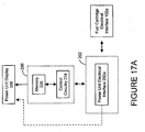
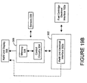
- power unit 200 also includes power unit electronics 206 and power unit display 208.
- the power unit electronics 206 includes circuitry to monitor, manage, control and/or store one or more operating parameter(s) of, for example, fuel cartridge 100 and/or power unit 200.
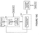
- the power unit display 208 may be appropriately disposed on or in (for example, in a recessed manner) power unit 200 to permit a user or operator to obtain information, for example, the status of the one or more operating parameter(s) of fuel cartridge 100 and/or power unit 200, from power unit electronics 206 and/or fuel cartridge electronics 106.
- the information may be calculated, determined and/or measured by power unit electronics 206 and/or provided to power unit display 208 by fuel cartridge electronics 106 via the electrical interfaces of cartridge interface 102 and power unit interface 202.
- cartridge display 108 may provide the status of the one or more operating parameter(s) of fuel cartridge 100 and/or power unit 200.
- the information to be displayed may be calculated, determined and/or measured by fuel cartridge electronics 106, as mentioned above, and/or provided to cartridge display 108 by power unit electronics 206 via the electrical interfaces of power unit interface 202 and cartridge interface 102.
- a user or operator may visually examine one or more operating parameter(s) of fuel cartridge 100 and/or power unit 200) using cartridge display 108 in addition to or in lieu of power unit display 208.
- power unit 200 may also include (in addition to or in lieu of power unit display 208) an audible indicator (not illustrated) to audibly provide one or more operating parameter(s) of fuel cartridge 100 and/or power unit 200) to the user or operator.
- the power unit 200 also includes fuel cell 210 to convert the fuel provided by fuel cartridge 100 to electrical power.
- the fuel cell 210 provides electrical power to an external device, for example, a camera or computer, via an electrical interface of power unit electronics-206.
- fuel cell 210 generally includes an anode end for splitting hydrogen atoms into electrons and protons, a current bearing portion providing a pathway for the electrons, a medium such as a proton exchange membrane providing a pathway for the protons, and a cathode end for rejoining the electrons and protons into water molecules in the presence of oxygen.
- the fuel cell 210 will be discussed in considerably more detail below.
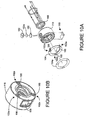
- Fuel Vessel 110 With reference to FIGURES 2 , 3A , 3B , and 3C in one embodiment, fuel cartridge 100 includes fuel vessel 110 for storing fuel for example, hydrogen or methanol, at an elevated pressure:
- the vessel 110 is preferably designed to be a cylinder having a thickness that is sufficient to withstand typical pressures at which the particular fuel is stored.
- cartridge 100 may typically store hydrogen at a pressure up to 5,500 pounds per square inch (PSI).
- PSI pounds per square inch
- the nominal operating pressure of fuel vessel 110 containing hydrogen is about 250 PSI with the maximum operating pressure of about 600 PSI, with a nominal test pressure of about 2,200 PSI and a nominal burst pressure of 5,100 PSI.
- the material of fuel vessel 110 is aluminum such as 6061 aluminum.
- the vessel 110 is of a conventional shape including a necked-down area 112 that has internal threads 114 that act as a securing element for cartridge valve assembly 104.
- the fuel vessel 110 also includes a collar-attaching mechanism 116, illustrated as threads.
- the collar-attaching mechanism 116 facilitates connecting cartridge collar assembly 118 to fuel vessel 110 via reciprocal threads of cartridge collar assembly 118 and the threads of collar-attaching mechanism 116. (See, FIGURE 3C ).
- cartridge collar assembly 118 is a mechanism to attach cartridge electronics 106 and cartridge display 108 to fuel vessel 110.
- chamber 110a of fuel vessel 110 will be particles of hydride material, not shown, that absorbs hydrogen to aid in the storage of hydrogen and/or enhance the capacity of storage of hydrogen in vessel 110.
- Cartridge Valve Assembly 104 The cartridge valve assembly 104 that allows a controlled exchange of fuel, in the form of a fluid, from fuel cartridge 100 to power unit 200.
- the cartridge valve assembly 104 may be securely fixed to fuel vessel 110 via threads that mate with internal threads 114 of fuel vessel 110. (See, for example, FIGURE 3C ).
- cartridge valve assembly 104 includes at least two states, including a first or activated state, whereby fuel may flow either out of or into chamber 110a of fuel cartridge 100. In a second or inactive state, cartridge valve assembly 104 prevents or prohibits fuel flow and, as such the fuel is contained within chamber 110a.
- the cartridge valve assembly 104 includes valve seal 128 which is designed to prevent fluid leakage from chamber 110a of fuel cartridge 100. (See, for example, FIGURES 3C ).
- fuel flows out of fuel cartridge 100 when, for example, fuel cartridge 100 is employed as a fuel source for power unit 200.
- fuel may flow into fuel cartridge 100 when, for example, fuel cartridge 100 is being filled or refilled (for example, periodically, intermittently, or as needed).
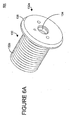
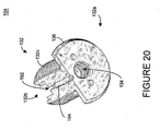
- cartridge valve assembly 104 includes poppet assembly 122.
- the poppet assembly 122 includes a distal end 122a and a proximal end 122b.
- the position of flange 124, relative to cartridge valve assembly 104 permits the flow of gas (i.e., flow around flange 124).
- flange 124 is multisided, including at least one flat side 124a around the edge of flange 124. Notably, the number of sides may be any number but is generally greater than two.
- flange 124 includes three flat sides along with three curved sides 124b.
- other designs are suitable and will be apparent to one of skill in the art, in view of this description. For example, notched, scalloped and/or drilled hole designs may be implemented.
- the poppet assembly 122 further includes an internal fluid passage 126.
- internal fluid passage 126 extends the length of poppet assembly 122.
- Other designs of internal fluid passage 126 are suitable and will be apparent to one of skill in the art, in view of this description. Indeed, other embodiments of internal fluid passage 126 are discussed below.
- the poppet assembly 122 may also include sealing ring 128 to enhance or provide a sufficient seal when poppet assembly 122 is disposed in combination with the other elements of cartridge valve assembly 104.
- a fluid conduit 126a extends from internal fluid passage 126 to the external surface at distal end 122a of poppet assembly 122.
- a burst disc 130 is located at proximal end 122b of poppet assembly 122 and is retained in place by retainer 130a which may be specifically designed or suitable for burst disc 130. Notably, burst disk 130 and retainer 130a may be separate components or may be manufactured as a unitary component.
- the retainer 130a fits onto proximal end 122b of poppet assembly 122 by means of threads that reciprocate with the internal threads on retainer 130a or other means apparent to one of skill in the art in view of this description. (See, FIGURE 4A ).
- a "circle" of solder may be disposed on burst disk 130 and retainer 130a is fitted onto the threads at proximal end 122b of poppet assembly 122 and thereafter heated to further secure burst disk 130 and retainer 130a to proximal end 122b of poppet assembly 122.
- the burst disk 130 may also be secured by crimping in place the retainer 130a to the proximal end 122b of poppet assembly 122.
- burst disk 130 may also function as a pressure relief device.
- burst disk 130 may be designed to open at a preset pressure and close when the pressure drops below a predetermined pressure.
- burst disc 130 may be rated at a certain pounds per square inch rating which is less than the rating for fuel vessel 110 (illustrated in FIGURES 3A-3C ). Generally, burst disc 130 may be rated from 500- 3,000 lbs. per square inch.
- cartridge valve assembly 104 further includes valve assembly housing 132 having distal end 132a and a proximal end 132b.
- An assembly housing cavity 134 extends the length of elongate valve assembly housing 132.
- the valve assembly housing 132 includes a radially extending flange 136 located at distal end 132a of housing 132.
- the external surface 132c of valve assembly housing 132 includes threads for securing cartridge valve assembly 104 to fuel vessel (via internal threads 114 as illustrated in FIGURE 3C ).
- An internal shoulder in valve assembly housing 132 restricts internal cavity 134 to facilitate secure "seating" and/or placement of sealing ring 128 of poppet assembly 122.
- the cartridge valve assembly 104 further includes spring 138 that fits against poppet assembly 122 and pushes against flange 124.
- a fastener 140a illustrated in this example as a snap ring, fits against washer 140b and spring 138 to retain the washer-spring poppet assembly and sealing ring 128 within housing cavity 134 of valve assembly housing 132. Once the snap ring is in place, multi-sided flange 124 fits against the shoulder of valve assembly housing 132 with sealing ring 128 positioned to seal the internal section of cartridge valve assembly 104.
- a particle filter 142 maybe positioned at proximal end 132b (when assembled) of valve assembly housing 132 designed to maintain and/or retain any particulate matter that is in cavity 110a of fuel vessel 110.
- the particle filter 142 allows fuel in the form of a fluid (for example, hydrogen or methanol), to flow through while retaining any solids inside vessel 110 (for example, hydride).
- one or more sealing rings 144 may be positioned inside distal end 132a of housing cavity 134 to enhance the integrity of cartridge valve assembly 104 when combined with the other components of fuel cartridge 100. In this way, the seal of the fuel or fluid path between fuel cartridge 100 and power unit 200 (or refill station 300 if applicable), when engaged or connected, is enhanced.
- cartridge valve assembly 104 in the closed state when flange 124 of poppet assembly 122 and sealing ring 128 are pushed against the internal shoulder of housing cavity 134 by spring 138.
- fuel i.e., fluid
- the proximal end 132b fits inside vessel 110.
- the particle filter 142 located, positioned and designed to allow fluid flow but prevent and/or minimize any particulate matter from escaping vessel 110.
- cartridge valve assembly 104 is in an open state (whereby fluid may flow into or out of chamber 110a) when flange 124 of poppet assembly 122 and sealing ring 128 (i.e. at distal end 122a of poppet assembly 122) are forced or pushed away from the internal shoulder of housing cavity 134.
- a void 146 forms between flange 124/sealing ring 128 and the internal shoulder of housing cavity 134 thereby allowing fluid or fuel (for example, hydrogen) to flow under pressure (into or out of chamber 110a) between particle filter 142, internal cavity 134 of housing 132, spring 138, around gap 148 into void 146 and through fluid conduit 126a to internal fluid passage 126.
- distal end 122a of poppet assembly 122 is pushed by pins (not illustrated) of power unit 200 or refill unit 300 that protrude into cartridge valve assembly 104 on a front surface of flange 136. This action or operation will be described and illustrated in detail below.
- the cartridge valve assembly may be implemented using many different designs. Such alternative designs are intended to fall within the scope of this invention. Indeed, all types of cartridge vale assemblies are intended to fall within the scope of this invention.
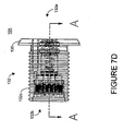
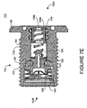
- cartridge valve assembly 104 includes poppet assembly 122 having an internal fluid passage that is closed by cap 150 so that the passage does not extend the entire length of poppet assembly 122, but the passage still communicates with fluid conduit 126a.
- a flange or shoulder 152 is located at distal end 122a of poppet assembly 122.
- the cartridge valve assembly 104 of this embodiment also includes spring 154 that fits over tip 150 of poppet assembly 122.
- the spring 154 is designed to be a "weaker” spring than spring 138 and, as such, spring 154 tends to compress before and at a greater rate than spring 138.
- cap 158a fits over spring 154 and snap ring 156 fits around spring 154.
- spring 138 is stronger than spring 154, the closed state or position will be the natural position or non-enabled state taken by cartridge valve assembly 104.
- spring 138 will push or force poppet assembly 122 that sealing ring 128 lodges against the shoulder of valve assembly housing 132 thereby effectively preventing any flow of fluid through housing cavity 134.
- cartridge valve assembly 104 is placed in an open state when front surface 158b of cap 158a of cartridge valve assembly 104 is engaged by a pin or stub component (not illustrated) of either power system 200 or refill unit 300 (as discussed in detail below) via housing cavity 134 at distal end 132a of valve assembly housing 132.
- spring 154 is compressed and forces or pushes cap 158a to bottom out on snap ring 156 of valve assembly 104.
- the pin or stub component (not illustrated) has a further extension or finger that extends from its tip and is of a diameter that will extend through an opening on front surface 158b of cap 158a.
- cartridge valve assembly 104 In operation, when fuel cartridge 100 is connected to power unit 200 and/or refill unit 300, cartridge valve assembly 104 is automatically opened by connection at the interface of unit 200 and/or refill unit 300.
- a male-type extension on the interface of power unit 200 and/or refill unit 300 engages a female-type receptacle of mechanical interface 102b of fuel cartridge 100 at a distal end 132a of cartridge valve assembly 104 to engage, activate and/or push poppet assembly 122 from a closed position or state (see, for example, FIGURES 6B and 7E ) to an open position or state (see, for example, FIGURES 6C and 7F ).
- cartridge valve assembly 104 automatically closes to thereby seal and/or retain the fluid/fuel in vessel 110 and maintain an appropriate pressure of the fuel in fuel cartridge 100.
- a pin or stub component of power unit valve assembly 204 or refill unit valve assembly 304 (discussed below with respect to power unit 200 and refill unit 300, respectively) having two segments, one that is positioned against the top of cap 158a and a finger or extension that fits through the opening on front surface 158b of cap 158a, several advantages may be gained, including: (1) the valve is protected from dirt, etc.
- cap 158a is designed to be of such a distance that even if it is pushed down by foreign object such as a pen tip, the tip of the pen does not contact poppet tip 150; and (3) even if a sharp item such as a paper clip were inserted into valve 104 there would not be sufficient leverage on contacting the rounded poppet tip 150 to open it (thereby presenting safety feature against the improper discharge of fuel).
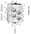
- Cartridge Collar Assembly 118 is a mechanism that secures or attaches cartridge interface 102, cartridge electronics 106 and cartridge display 108 to fuel vessel 110. With reference to FIGURES 8A and 8B , in one embodiment, cartridge collar assembly 118 is attached to necked-down area 112 of fuel vessel 110. The electrical interface 102a, mechanical interface 102b and display are fixed on, in and/or to cartridge collar assembly 118 to facilitate communication to other components of fuel cell power and management system 10. In addition, an opening in cartridge collar assembly 118 exposes cartridge valve assembly 104, when secured to fuel vessel 110, to allow fluid communication between cartridge valve assembly 104 and, for example, power unit 200 and/or refill unit 300.
- cartridge collar assembly 118 illustrated and described herein is an exemplary technique/architecture that is a compact, lightweight and efficient design. It is intended that all techniques and architectures to secure cartridge interface 102, cartridge electronics 106 and/or cartridge display 108 (and/or any other components) to fuel vessel 110 of fuel cartridge 100, whether now known or later developed, fall within the scope of the present invention. Indeed, in those instances where one or more of such components need not be fixed to, for example, fuel vessel 110, in order to provide a unitary and/or integrated fuel cartridge 100, cartridge collar assembly 118 may not be necessary and/or advantageous.
- cartridge interface 102, cartridge electronics 106 and cartridge display 108 are disposed on, in and/or to cartridge collar assembly 118.
- cartridge display 108 may be a visual display of information (for example, an LCD or LED device) that provides or affords the user or operator the ability to view, for example, various parameters of fuel cartridge 100 and/or other units of fuel cell power and management system 10.
- a protective cover or membrane 108a may be disposed over cartridge display 108.
- contact switch 108b (for example, a contact button) may be employed to activate cartridge display 108 in those instances where display 108 is not continuously “on” (for example, when fuel cartridge 100 is in a "power saver” mode and/or when fuel cartridge 100 is idle).
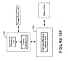
- power source 160 (for example, a battery) may be employed to provide power to, for example, the circuitry of cartridge electronics 106 and cartridge display 108.
- the power source 160 may be disposable, non-renewable or renewable.
- a cover plate 162 protects the battery from damage, secures power source 160 to or in cartridge collar assembly 118 and, in the context of a battery, facilitates removal and replacement thereof.
- battery compression pad 162a may be employed to maintain power source 160 in the appropriate position as well as ensure or enhance sufficient electrical contact between power source 160 and other circuitry of fuel cartridge 100.
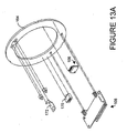
- electrical interface 102a includes circuit board 164 (illustrated in this exemplary embodiment as a ring printed circuit board) to provide electrical interconnection between the circuitry of fuel cartridge 100.
- the circuit board 164 may be fitted with a plurality of electrical contact points (illustrated as electrical contact pads 166) to facilitate electrical communication to devices external to fuel cartridge 100.
- electrical contact pads 166 there are three equally spaced distances around circuit board 164.
- a circuit board cover 164a having suitably located "cut-out" areas or openings 164b is fitted so that contacts 166 are exposed when circuit board cover 164a is disposed on circuit board 164.
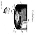
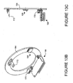
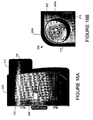
- electrical contact pads 166 are disposed and located on circuit board 164 and externally exposed via openings in cartridge collar assembly 118. (See, for example, FIGURE 11 B) . In this way, contact pins of electrical interface 202a and 302a of power unit 200 and refill unit 300, respectively, may engage electrical contacts 166 to provide suitable electrical communication and/or connection therebetween. (See, for example, FIGURES 11A , 16B and 18B ).
- circuit board 164 includes three sets of contact pads 166 at three positions or locations on circuit board 164. (See, for example, FIGURE 11 B) . These positions or locations are consistent with or conform to the mating operation of the mechanical interfaces of power unit 200 and refill unit 300. However, one skilled in the art, in view of this disclosure, will recognize that one set of contact pads 166 is sufficient to provide electrical communication between fuel cartridge 100 and power unit 200 (or refill unit 300).
- contact pads 166 are gold plated for easy contact.
- a ground first contact arrangement may be advantageous; however, other arrangements are suitable.
- a retention ring may be attached to an adapter guide using screws, detent springs and balls.
- the adapter guide and the retention ring may be press fit within cartridge collar assembly 118, and then "sandwiched" between fuel vessel 110 and cartridge collar assembly 118.
- various components for example, circuit board 164 and circuit board cover 164a may be securely housed and/or retained within cartridge collar assembly 118.
- fuel cartridge 100 also includes mechanical interface 102b to "mate" with the mechanical interface of power unit 200 or refill unit 300 (for example, when fuel cartridge 100 is a rechargeable-type) to facilitate a controlled, continuous and/or uninterrupted exchange of fuel from fuel cartridge 100 to power unit 200 (or to fuel cartridge 100 from refill unit 300, if applicable).
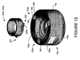
- mechanical interface 102b is disposed in cartridge collar assembly 118 to provide a relatively compact design that facilitates attachment of fuel cartridge 100 (and, in particular, fuel vessel 110 and cartridge valve assembly 104) to, for example, power unit 200 or refill unit 300. (See, for example, FIGURES 12 , 16B and 18B ).
- An adapter guide 168 which is part of cartridge mechanical interface 102b, may be fitted into cartridge collar assembly 118 to aid in securing in fuel cartridge 100 to power unit 200 or refill unit 300.
- cartridge mechanical interface 102b includes a female-type receptacle to engage a male-type mechanical interface 202b and mechanical interface 302b of power unit 200 and refill unit 300, respectively.
- the exemplary male-type mechanical interface includes an "ear" having a beveled edge that fits into the recess of the female-type receptacle mechanical interface 102b.
- the "ear”, and in particular the beveled edge is designed to meet with a shoulder of the female-type receptacle mechanical interface 102b. Thereafter, an approximate quarter turn secures fuel cartridge 100 into power unit 200 or refill unit 300.
- This interface design requires little twisting motion and force to secure fuel cartridge 100 into power unit 200 or refill unit 300 and is designed to be oriented at any one of three positions. As such, this design prevents push back of fuel cartridge 100 by mechanically engaging the female-type receptacle of mechanical interface 102b before opening cartridge valve assembly 104 of fuel cartridge 100.
- mechanical interface 102b of fuel cartridge 100 includes several elements that facilitate a "smooth" interface of fuel cartridge 100 with power unit 200 and/or refill unit 300.
- mechanical interface 102b in this embodiment, is a "female-type receptacle” that cooperates with cartridge valve assembly 104 of fuel cartridge 100.
- the mechanical interface 102b is designed to receive a male extension of power unit 200 and/or refill unit 300, as illustrated in FIGURE 12 .
- the female-type receptacle of mechanical interface 102b provides a way to align, insert, captivate, and retain fuel cartridge 100 in power unit 200 and/or refill unit 300.
- the design of mechanical interface 102b also facilitates the actuation of cartridge valve assembly 104 to permit or prevent the flow of fluid in or out of fuel cartridge 100.
- a male-type extension of mechanical interface 202b of power unit 200 and/or mechanical interface 302b of refill unit 300 is associated with the female-type receptacle of mechanical interface 102b.
- the male-type extension mechanical interface 202b of power unit 200 and/or mechanical interface 302b of refill unit 300 is designed to engage female-type receptacle of mechanical interface 102b of fuel cartridge 100 to provide a means for the alignment, insertion, captivation, and retention of fuel cartridge 100 therein.
- cartridge display 108 and cartridge electronics 106 are mounted on circuit board 164.
- the circuit board 164 includes electrical traces to interconnect the various components, including cartridge display 108, cartridge electronics 106 and electrical interface 102a.
- the connector 170 shown as a 4-circuit connector, is located on the underside of circuit board 164.
- the connector 170 may be employed to, among other things, test various components and features of cartridge display 108 and cartridge electronics 106 are mounted on circuit board 164.
- the power source contact 172 engages power source 160 (for example, a battery) to provide a suitable voltage and current to the circuitry and components interconnected by the electrical traces on circuit board 164.
- power source 160 for example, a battery
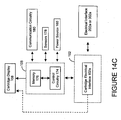
- cartridge electronics 106 includes control circuitry 174 to determine, monitor, manage and/or control one or more operating parameters of fuel cartridge 100, power unit 200 and/or fuel cell power and management system 10.
- the control circuitry 174 may be a combination of discrete components or may be an integrated circuit(s), for example, one or more suitably programmed (whether in situ or prior to deployment) microprocessors, microcontrollers, state machines and/or field programmable gate arrays ("FPGAs").
- the control circuitry 174 receives electrical power from power source 160 (for example, a rechargeable or non-rechargeable battery).
- cartridge electronics. 106 also includes memory 176, for example, SRAM, DRAM, ROM, PROM, EPROM and/or EEPROM.
- data or information representative of one or more operating parameters and/or microcode may be stored in, for example, an SRAM, DRAM, ROM or EEPROM.
- the data or information representative of one or more operating parameters may include a current status and/or historical data.
- memory 176 may be comprised of discrete component(s) or may reside on or in an integrated circuit that performs other non-memory operations, for example, control circuitry 174.
- cartridge memory 176 may store or retain one or more attributes of the associated fuel cartridge 100.
- cartridge memory 176 may store data that uniquely identifies the associated fuel cartridge 100 (for example, an associated serial number, date of manufacture and/or assembly, data pertaining to the supplier of one or more components of fuel cartridge 100, fuel capacity, number of refills (if applicable) and dates thereof, revision or series of electronics/software, and/or type of fuel) and/or more generally identifies the associated fuel cartridge 100 (for example, model number).
- cartridge memory 176 may also include a filling algorithm for cartridge 100.
- cartridge memory 176 may have available the unique and general characteristics (for example, capacity and type of fuel) of cartridge 100 to be provided to power unit 200, refill unit 300 (if applicable) or a user/operator, which can confirm, verify or ensure proper operation and integration.
- control circuitry 174 may determine, monitor, manage and/or control one or more operating parameters, for example, the amount of fuel remaining and/or consumed, the rate of fuel consumption, the temperature and pressure of the fuel in fuel vessel 110a, temperature of the exterior of fuel vessel 110a, and the operating status of fuel cartridge 100 (for example, whether any faults or errors have been registered). For example, control circuitry 174 may calculate, determine and/or monitor the amount of fuel remaining and/or consumed, as well as the rate of fuel consumption, based on an amount of time fuel cartridge 100 has been connected to and providing fuel to power unit 200 and/or connected to and receiving fuel from refill unit 300 (where fuel cartridge 100 is a rechargeable type). This status may be periodically updated and/or stored in memory 176 for access by, for example, power unit 200 and/or refill unit 300.
- operating parameters for example, the amount of fuel remaining and/or consumed, the rate of fuel consumption, the temperature and pressure of the fuel in fuel vessel 110a, temperature of the exterior of fuel vessel 110a, and the operating status of fuel cartridge 100 (for example,
- control circuitry 174 may receive, sample and/or acquire data from sensors 178 (for example, temperature, pressure and/or flow rate type sensors) disposed on, in or near cartridge vessel 110a, cartridge valve assembly 104, and/or cartridge interface 102.
- the control circuitry 174 may employ data from sensors 178 to calculate one or more operating parameters of fuel cartridge 100 using mathematical relationships and/or modeling.
- control circuitry 174 may obtain data which is representative of the temperature and pressure of the fuel in fuel cartridge vessel 110a and, based thereon, calculate/estimate the amount of fuel consumed from and remaining in fuel cartridge vessel 110a.
- control circuitry 174 may obtain data which is representative of the flow rate of fluid through cartridge valve assembly 104 and, using time data, calculate the amount of fuel remaining in fuel cartridge vessel 110a and amount of time until all fuel is spent from fuel cartridge 100.
- the sensors 178 may be discrete elements, such as one or more micro electromechanical (“MEMS”) devices, or sensors that are integrated into cartridge vessel 110a, cartridge valve assembly 104, and/or cartridge interface 102, or into components thereof (for example, one or more temperature elements integrated into and disposed within the walls of cartridge vessel 110a or in valve assembly housing 132).
- MEMS micro electromechanical
- any type of sensor for example, MEMS, whether now known or later developed, may be implemented herein.
- control circuitry 174 may receive instructions and/or data from circuitry external to fuel cartridge 100, for example, from a user or an operator via an external device (computer or PDA), and/or from power unit 200 or refill unit 300.
- control circuitry 174 may be instructed to, for example, determine, measure, sample one or more operating parameters, and thereafter control and/or manage the operation of fuel cartridge 100 and/or power unit 200 (for example, adjust and/or modify the rate of fuel consumption and/or the temperature of the exterior of fuel vessel 110a (and indirectly the temperature of the fuel in fuel vessel 110a) by engaging a cooling unit disposed on power unit 200.
- control circuitry 174 provides and/or communicates the measured, sampled, sensed and/or determined operating parameter(s) to power unit 200, refill unit 300 and/or a user or an operator.
- control circuitry 174 may determine the state of fill or amount of fuel remaining in fuel vessel 110a (using the techniques described above) and, thereafter, provide data which is representative of that operating parameter to power unit 200.
- power unit 200 may adjust one or more of its operating parameters, for example, reduce the rate of power/fuel consumption.
- an operator or a user may receive data which is representative of the state of fill or amount of fuel remaining in fuel vessel 110a from fuel cartridge 100 and, in response thereto, modify or change the operating characteristics of power unit 200 (directly or remotely).
- one or more operating parameters for example, reduce the fuel consumption and/or electrical power output/generation, or engage a cooling unit to influence the temperature of fuel vessel 110a
- one or more operating parameters may be modified and/or changed.
- the modification or change to the operating characteristics of power unit 200 may be preset, predetermined and/or pre-programmed. In this way, the response is present, predetermined and/or pre-programmed based on the conditions, operating characteristics and/or operating parameters of power unit 200 and/or fuel cartridge 100.
- instructions defining the modification or change to the operating characteristics may be transmitted or provided by the operator, user or external device (for example, the user determines the appropriate modification or change based on one or more considerations, factors, constraints and/or objectives).
- such instructions and/or data may be received or transmitted via communication circuitry 180.
- communication circuitry 180 may employ well known wired (for example, a serial input/output port) and/or wireless techniques (for example, infrared, radio frequency, cellular phone, bluetooth techniques).
- the instructions and/or data may be provided remotely via wireless techniques.
- any communication technique whether now known or later developed, is intended to fall within the scope of the present invention.
- communication circuitry 180 may be employed to transmit data and/or commands to power unit 200, refill unit 300 and/or other external devices (for example, to a local or remote computer).
- the data may be representative of one or more operating parameters (that were measured, sampled, sensed by sensors 178 and/or determined by control circuitry 174) such as temperature, pressure, rate of fuel consumption by power unit 200, and/or amount of remaining fuel in fuel cartridge 100.
- the data may also be representative of the overall status of fuel cartridge 100.
- communication circuitry 180 may employ wired or wireless techniques.
- cartridge electronics 106 includes memory 176 to store and/or retain data provided by power unit 200, refill unit 300 and/or circuitry external to system 10.
- power unit 200 and/or refill unit 300 may, among other things, determine, monitor and/or control one or more operating parameters, for example, the amount of fuel remaining and/or consumed, the rate of fuel consumption and/or the temperature and pressure of the fuel in fuel vessel 110a.
- the power unit 200 and/or refill unit 300 may periodically or intermittently store data which is representative of the one or more operating parameters in memory 176.
- the status of the fuel cartridge (for example, the amount of fuel remaining) is retained within the fuel cartridge's memory (i.e., memory 176) so that it may be available for recall by power unit 200, refill unit 300 and/or circuitry external to system 10.
- memory 176 i.e., memory 176
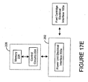
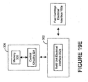
- communication circuitry 180 it may be advantageous to include communication circuitry 180 in order to facilitate access to memory 176. (See, for example, FIGURE 14E ).
- control circuitry 174 performs or executes routines or programs that implement particular tasks and/or operations described herein.
- routines or programs may be combined or distributed.
- Such programming is well known to those skilled in the art, particularly in view of this disclosure. All programming techniques, and implementations thereof, to determine, monitor, manage and/or control one or more operating parameters and/or characteristics of fuel cartridge 100, power unit 200 and/or refill unit 300, whether now known or later developed, are intended to fall within the scope of the present invention.
- control circuitry 174 is a microcontroller integrated circuit having EEPROM resident therein.
- the power source 160 in this embodiment, is a battery that provides electrical power to the circuitry/devices of cartridge electronic 106 (for example, microcontroller) and cartridge display 108 (for example, an LCD or LED display). Where an LCD display is implemented, it may be advantageous to include a backlight 108c which provides suitable lighting when the ambient light may not be sufficient.
- the contact switch 108b enables backlight 108c. That is, when contact switch 108b is depressed, backlight 108c will illuminate the LCD display.
- Exemplary Assembly of Fuel Partridge 100 In those instances where fuel cartridge employs a hydride material, after fabrication of fuel vessel 110, an appropriate hydride material may be disposed therein. Such material is well known in the art. Thereafter, cartridge valve assembly. 104 may be inserted and secured to vessel 110 via internal threads 114 and corresponding threading 132c on valve assembly housing 132. (See, for example, FIGURE 8A ). The cartridge collar assembly 118 may be secured to vessel 110 via collar-attaching mechanism 116 (for example, by screwing collar assembly 118 onto cartridge vessel 110).
- cartridge electronics 106 may be configured to determine, monitor, manage and/or control one or more operating parameters of fuel cell power and management system 10 (for example, to characterize the state of fill of fuel cartridge 100).
- cartridge electronics 106 may be configured to determine, monitor, manage and/or control one or more operating parameters in situ (i.e., in the field or when deployed).
- fuel cell power and management system 10 includes power unit 200 to generate electricity using fuel stored in and provided from fuel cartridge 100.
- the power unit 200 includes an interface and valve assembly that connects to or mates with corresponding components of one or more fuel cartridge(s) 100.
- the fuel for example, hydrogen or methanol
- the fuel vessel 110 is supplied, under pressure, to power unit 200 which generates electricity therefrom.
- power unit 200 includes power unit interface 202 and power unit valve assembly 204 which are configured to connect to or mate with fuel cartridge 100.
- the power unit 200 also includes power unit electronics 206 and power unit display 208.
- power unit electronics 206 includes circuitry to determine, monitor, control and/or store one or more operating parameter(s) of, for example, fuel cartridge 100 and/or power unit 200.
- the power unit display 208 for example, an LCD or LED display, may be conveniently located on housing 212 to facilitate observation by and/or exchange information with a user, for example, the status of the one or more operating parameter(s), from cartridge electronics 106 and/or power unit electronics 206 to a user or an operator.
- a user or an operator may, for example, view data which is representative of the status off the one or more operating parameter(s) of fuel cartridge 100 and/or power unit 200 (for example, the amount of fuel remaining and/or consumed, the rate of fuel consumption, the temperature and pressure of the fuel in fuel vessel 110a, and the operating status of fuel cartridge 100, for example, any faults or errors therein).
- operating parameter(s) of fuel cartridge 100 and/or power unit 200 for example, the amount of fuel remaining and/or consumed, the rate of fuel consumption, the temperature and pressure of the fuel in fuel vessel 110a, and the operating status of fuel cartridge 100, for example, any faults or errors therein.
- power unit 200 may include (in addition to or in lieu of display 208) an audible indicator (not illustrated) to audibly provide information which is representative of status of the one or more operating parameter(s), to the user or operator.
- the power unit 200 also includes fuel cell 210.
- the fuel cell 210 employs that fusel (for example, hydrogen, hydride or methanol) to generate electricity.
- the fuel cell 210 includes a fuel cell stack.
- a particularly preferred fuel cell power system is the one that is described in U.S. Patent Application No. 10/328,709, filed December 24, 2002 , which, as mentioned above, is incorporated herein by reference in its entirety.
- this application describes, among other things, a forced air fuel cell system in which an air moving device configured to direct atmospheric air towards the cathode end of the plurality of fuel cells is positioned and thus convectively cools the fuel cell as it supplies atmospheric air to the cathode end which aids in the generation of electricity.
- power unit 200 includes a housing having cartridge port 214 to receive fuel cartridge 100.
- the power unit 200 of this embodiment secures or is connected (electrically and/or mechanically) to an external device (not illustrated) that receives electrical power from (and generated by) power unit 200.
- the electrical interface 202a and mechanical interface 202b of power unit interface 202 are disposed in cartridge port 214.
- the electrical interface 202a is designed to connect with electrical interface 102a of fuel cartridge 100.
- electrically conductive contact pins 216 of electrical interface 202a which is disposed on housing 212, engage contacts 166 of electrical interface 102a. (See, for example, FIGURE 11A ).
- control circuitry 174 and/or memory 176 of cartridge electronics 106 may communicate (for example, provide data which is representative of one or more operating parameter(s) and/or determine, monitor, manage and/or control one or more operating parameter(s)) with, for example, power unit electronics 206 (control circuitry (if any) and/or memory (if any)) and/or power unit display 208.
- power unit 200 includes only one cartridge port 214 to receive one fuel cartridge 100. As mentioned above, however, power unit 200 may include a plurality of cartridge ports 214 to accommodate and receive more than one fuel cartridge 100.
- the contact pins 216 are preferably a miniature pogo pin style with a significant cycle life, for example, more than 100,000 cycles.
- electrical interface 202a includes five pins to provide a plurality of electrical signals, including power and ground, a thermistor sensor output signal, and data via a serial interface.
- the cartridge electronics 106 and power unit electronics 206 are designed to be "on" when a fuel cartridge 100 is in power unit 200.
- a triplicate contact pad configuration of fuel cartridge 100 is provided to support multi-orientation insertion and ease of operation in conjunction with electrically conductive contact pins 216.
- contact pins 216 may engage any one of the three contact pads on electrical interface 102a of fuel cartridge 100.
- the mechanical interface 202b is designed to hold, retain and engage at least one fuel cartridge 100.
- power unit valve assembly 204 may connect to provide fluid communication from fuel cartridge 100 to fuel cell 210 (and in particular the fuel cell stack of fuel cell 210).
- mechanical interface 202b includes a male-type interface to engage the female-type receptacle of cartridge mechanical interface 102b of fuel cartridge 100.
- the exemplary male-type mechanical interface includes an "ear" or tab 220 having a beveled edge 220a that fits into the recess of the female-type receptacle mechanical interface 102b. (See, for example, FIGURE 12 ).
- the beveled edge 220a of tab 220 meets with a shoulder of the female-type receptacle mechanical interface 102b. Thereafter, an approximate quarter turn secures fuel cartridge 100 into power unit 200. Notably, this design prevents push back of fuel cartridge 100 by mechanically engaging the female-type receptacle of mechanical interface 102b before opening cartridge valve assembly 104 of fuel cartridge 100.
- actuating pin 222 engages (for example, pushes) distal end 122a of poppet assembly 122 by protruding into cartridge valve assembly 104 on a front surface of flange 136 (see, for example, FIGURE 7E and 7F ). As mentioned above, this action or operation places cartridge valve assembly 104 in an open state. Once fuel cartridge 100 is securely in place in power unit 200, fuel is then allowed to flow from cartridge 100 to power unit 200 to allow fuel cell 210 to operate.
- power unit 200 includes a conduit that extends from power unit valve assembly 204 to fuel cell 210.
- the power unit valve assembly 204 includes a valve, having a regulator that is connected to the conduit to regulate pressure and/or control the flow of fuel to the fuel cell stack of fuel cell 210.
- the regulator selects and regulates fuel pressure including parameter for feeding fuel contained in fuel cartridge 100 to the fuel cell stack. Accordingly, while fuel may be capable of flowing, under pressure, after fuel cartridge 100 is securely in place in power unit 200, the regulator in power unit valve assembly 204 regulates the pressure of fuel feed to the fuel cell 210.
- power unit electronics 206 includes control circuitry 224 to determine, monitor, manage and/or control one or more operating parameters of fuel cartridge 100, power unit 200 and/or fuel cell power and management system 10.
- the control circuitry 224 may be implemented and/or configured like control circuitry 174 of fuel cartridge 100. Accordingly, the discussion pertaining to the features, implementation, embodiments, operation and configuration of control circuitry 174 is fully applicable to control circuitry 224; that is, control circuitry 224 may be implemented or configured in the same or similar manner, and/or perform the same or similar operations as control circuitry 174. For the sake of brevity, those discussions will not be repeated but will be summarized below in connection with control circuitry 224.
- the control circuitry 224 determines, monitors, manages and/or controls one or more operating parameters, for example, the amount of fuel remaining and/or consumed, the rate of fuel consumption, the temperature and pressure of the fuel in fuel vessel 110a, temperature of the exterior of fuel vessel 110a, and the operating status of fuel cartridge 100 (for example, whether any faults or errors have been registered) and/or the operating status of power unit 200.
- control circuitry 224 may calculate, determine and/or monitor the amount of fuel remaining in fuel cartridge 110, as well as the rate of fuel consumption, using information pertaining to the amount of time fuel cartridge 100 is connected to and providing fuel to power unit 200.
- control circuitry 224 may receive, sample and/or acquire data from sensors 178 and/or sensors 230 (for example, temperature, pressure and/orflow rate type sensors) disposed on, in or near cartridge vessel 110a, cartridge valve assembly 104 and/or power unit valve assembly 204. (See, for example, FIGURE 17B ).
- the control circuitry 224 may employ data from sensors 178 and/or sensors 230 to calculate one or more operating parameters using mathematical relationships and/or modeling. For example, control circuitry 224 may obtain data which is representative of the temperature and pressure of the fuel in fuel cartridge vessel 110a and, based thereon, calculate%stimate the amount of fuel consumed from and/or remaining in fuel cartridge vessel 110a.
- control circuitry 224 may obtain data which is representative of the flow rate of fluid through fuel cartridge valve assembly 104 and, using time data, calculate the amount of fuel remaining in fuel cartridge vessel 110a and amount of time until all fuel is spent from fuel cartridge 100.
- control circuitry 224 may be a combination of discrete components or may be an integrated circuit(s), for example, one or more suitably programmed (whether in situ or prior to deployment) microprocessors, microcontrollers, state machines and/or FPGAs.
- power unit electronics 206 also includes memory 226, for example, SRAM, DRAM, ROM, PROM, EPROM and/or EEPROM.
- memory 226, for example, SRAM, DRAM, ROM, PROM, EPROM and/or EEPROM.
- data or information which is representative of one or more operating parameters and/or microcode may be stored in, for example, an SRAM, DRAM, ROM or EEPROM.
- the data or information representative of one or more operating parameters may include a current status and/or historical data.
- memory 226 may be comprised of discrete component(s) or may reside on or in an integrated circuit that performs other non-memory operations, for example, control circuitry 224.
- sensors 230 may be discrete elements, such as one or more micro electromechanical (“MEMS”) devices, or sensors that are disposed near cartridge vessel 110a, and/or disposed in power unit valve assembly 204, and/or cartridge interface 202, or into components thereof (for example, one or more temperature elements integrated into and disposed in the housing of valve assembly 204).
- MEMS micro electromechanical
- control circuitry 224 may receive instructions and/or data from, for example, a user or an operator. In this regard, control circuitry 224 may be instructed to, for example, determine one or more operating parameters, and thereafter control and/or manage the operation of fuel cartridge 100 and/or power unit 200 (for example, adjust and/or modify the rate of fuel consumption and/or the temperature of the exterior of fuel vessel 110a (and indirectly the temperature of the fuel in fuel vessel 110a) by engaging a cooling unit disposed on power unit 200). In this way, the efficiency and/or control of system 10 is enhanced.
- control circuitry 224 provides and/or communicates the measured, sampled, sensed and/or determined operating parameter(s) to a user or an operator.
- control circuitry 174 may acquire data from sensors 178 and/or sensors 230 and thereafter determine the state of fill or amount of fuel remaining in fuel vessel 110a.
- the control circuitry 224 may provide data which is representative of that operating parameter to the user or operator.
- the user or operator may adjust one or more of the operating parameters of power unit 200, for example, reduce the amount of power/fuel consumption and/or reduce or adjust the output power of fuel cell 210.
- an operator or a user may receive data which is representative of the state of fill or amount of fuel remaining in fuel vessel 110a from control circuitry 224 (as calculated therein) and, in response thereto, instruct power unit 200 to modify or change its operating characteristics (directly or remotely), for example, reduce the fuel consumption and/or electrical power output/generation, or engage a cooling or a heating unit to influence the temperature of fuel vessel 110a (for example, in those instances where the temperature of the fuel during operation may not be suitable and/or optimum).
- the modification or change to the operating parameters of power unit 200 may be preset, predetermined and/or pre-programmed.
- the modification or change may also be in accordance with instructions transmitted or provided to control circuitry 224 (for example, the user determines the appropriate modification or change based on one or more considerations, factors, constraints and/or objectives).
- such instructions and/or data may be received or transmitted via communication circuitry 228.
- communication circuitry 228 may employ well known wired (for example, a serial input/output port) and/or wireless techniques (for example, infrared techniques). Indeed, the instructions and/or data may be provided remotely via wireless techniques.
- communication circuitry 228 may be employed to transmit data and/or commands to power unit 200, refill unit 300 and/or other external devices (for example, to a local or remote computer).
- the data may be one or more operating parameters (that were measured, sampled, sensed by sensors 178 and/or determined by control circuitry 224) such as temperature, pressure, rate of fuel consumption by power unit 200, and/or amount of remaining fuel in fuel cartridge 100.
- the data may also be representative of the overall status of power unit 200 and/or fuel cartridge 100.
- power unit 200 includes power unit electronic 206 as described above, (see, for example, FIGURES 17A , 17B and/or 17C), and fuel cartridge 100 includes memory 176 (see, for example, FIGURES 14D and 14E ) to store and/or retain data provided by power unit electronics 206.
- control circuitry 224 may, among other things, monitor one or more operating parameters, for example, the amount of fuel remaining and/or consumed, the rate offuel consumption, the temperature and pressure of the fuel in fuel vessel 110a, temperature of the exterior of fuel vessel 110a, and/or the operating status of fuel cartridge 100 (for example, whether any faults or errors have been registered).
- the control circuitry 224 may periodically or intermittently store data which is representative of the one or more operating parameters in memory 176.
- the status of the fuel cartridge (for example, the amount of fuel remaining) is retained within the fuel cartridge's memory (i.e., memory 176) so that it may be available for recall by power unit 200 (for example, another power unit 200 that has no "history" of the status of a given fuel cartridge 100) and/or refill unit 300.
- control circuitry 224 may also determine, monitor, manage and/or control other characteristics or operations of power unit 200, for example, thermal management, fuel leak detection, fuel purge, over-current protection and/or voltage regulation.
- control circuitry 224 may receive information representative of the temperature of one or more elements of power unit 200 (for example, fuel cell 210) and in response thereto adjust and/or manage the operation of power unit 200 (for example, adjust the rate of fuel consumption and/or generation of electricity).
- the sensors 230 may include fuel leak sensors to provide data of the status of the integrity of the fuel path (i.e., whether a leak is present) to control circuitry 224. In response thereto, control circuitry 224 may alert the user/operator of the leak (or possible leak) and/or may safely terminate operation of power unit 200.
- control unit 224 may, based on data from sensors 230, determine the existence of a (or potential) fuel leak.
- the control circuitry 224 may employ various techniques, which are well known to those skilled in the art, to assess whether there is a fuel leak. Again, control circuitry 224 may alert the user/operator of the leak (or possible leak) and/or may immediately and safely terminate operation of power unit 200.
- control circuitry 224 may also monitor the status of over-current protection and/or voltage regulation to assess the status of the power generation by fuel cell 210.
- control circuitry 224 may receive information representative of the current consumption and/or voltage levels from sensors 230 that provide information pertaining to the generation of electricity and/or consumption thereof. In response, control circuitry 224 may appropriately manage and/or control the operation of power unit 200.
- control circuitry 224 may perform or execute routines or programs that implement particular tasks and/or operations described herein.
- routines or programs may be combined or distributed.
- Such programming is well known to those skilled in the art, particularly in view of this disclosure. All programming techniques, and implementations thereof, to determine, monitor, manage and/or control one or more operating parameters and/or characteristics of fuel cartridge 100 and/or power unit 200, whether now known or later developed, are intended to fall within the scope of the present invention.
- fuel cell power and management system10 include, in addition to fuel cartridge 100 and power unit 200, refill unit 300.
- fuel cartridge may be filled with fuel (for example, hydrogen, methanol or other hydrogen containing compound) after some or all of the fuel is depleted from fuel cartridge 100 (for example, consumed by power unit 200) using refill unit 300.
- fuel for example, hydrogen, methanol or other hydrogen containing compound
- refill unit 300 includes refill unit interface 302, refill unit valve assembly 304, refill unit electronics 306 and refill unit display 308 (for example, a 24 character by two line LCD device).
- refill unit interface 302 and refill unit valve assembly 304 are configured to connect to or mate with associated or corresponding components of fuel cartridge 100. (See, for example, FIGURES 11A and 12 ).
- the configuration, architecture and design of refill unit interface 302 and refill unit valve assembly 304 may be the same as power unit interface 202 and power unit valve assembly 204, respectively. For the sake of brevity that discussion will not be repeated.
- the refill unit 300 may be a stand alone table top or wall mounted device, which may be installed, for example, at a facility or in a vehicle and thereby provide refilling capabilities for one or more fuel cartridges 100.
- refill unit 300 includes one or more refill ports 310 (four refill ports are illustrated) to accommodate one or more fuel cartridges 100.
- refill unit 300 in operation, replenishes one or more depleted fuel cartridges 100 and returns fuel cartridges 100 to a more filled state or a completely refilled state for use in power unit 200.
- each refill port 310 may function and/or may be operated independently of the other ports. In this way, fuel cartridges 100 having different fuel fill and/or capacity conditions may be returned to a more filled or completely refilled state independently. Moreover, fuel cartridges 100 may be randomly installed in refill ports 310.
- the refill port 310 includes an independent solenoid valve for providing fluid or fuel shutoff when not in use and a switch to sense whether a fuel cartridge 100 is inserted.
- the solenoid/switch combination permits random access to any refill port 310, semi-automatic initiation and termination of the refilling operation and provides positive fluid supply shutoff. It may be advantageous to maintain refill unit 300 in a position whereby fuel cartridges 100 are in a mostly horizontal orientation with respect to the center axis of fuel vessel 110a. In this way, it may prevent the introduction of foreign matter into the area of valve assembly 304 and refill port 310 and reduce and/or minimize possible malfunction or damage to the components in and near refill port 310 as a result of such foreign matter.
- refill unit 300 includes main fuel/fluid input port 314 to connect to a primary compressed fuel source (for example, a "K" bottle size tank).
- the main fuel/fluid input port 314 may be located on an outer surface of housing 312 to facilitate connection to the primary compressed fuel source.
- the main fuel/fluid input port 314 may provide local pressure regulation, for example, 250 PSI, and include a fluid shutoff to isolate the input of the primary compressed fuel source from refill unit 300 and/or fuel cartridge 100.
- main fuel/fluid input port 314 may also provide passive overpressure protection to prevent inadvertent overpressure exposure to refill unit 300 and/or fuel cartridge 100 which may be disposed therein.
- refill unit 300 may also include an auxiliary fuel/fluid output port 316 to facilitate expansion and operation of one or more additional refill units 300 without site modification (for example, modification of plumbing on the large fuel tank supporting refill unit 300 to accommodate additional refill units 300).
- the auxiliary fuel/fluid output port 316 may be located and/or mounted on an outer surface of housing 312 for connection to one or more additional refill units 300 (not illustrated). In this way, a series of fluid connection may be daisy chained from one refill unit to another and connected to one large fuel tank supply (for example, a "K" bottle size tank).
- the refill unit 300 may include one or more input pressure regulators to accept low pressure regulated gas from a high pressured tank, a normally closed main shut off solenoid valve with over pressure protection, and a gas distribution manifold to provide fluid to each of the plurality of refill ports 310.
- a plurality of solenoid valves may be employed to provide shutoff capabilities to each refill port 310 when in use.
- the plurality of electrical pins may be used to sense the presence of a fuel cartridge 100 in a given refill port 310.
- cooling unit 318 may employ one or more cooling circulation fans that are appropriately located to remove heat from one or more fuel cartridges 100 while connected to refill unit 300 and being re-filled.
- refill unit 300 may include a heating unit (not illustrated) to accommodate those instances where the temperature during the refill operation may not be suitable and/or optimum.
- the heating unit may apply heat to the fuel cartridge 100 to, for example, increase the efficiency of the refill operation and thereby reduce the refill time.
- the refill unit 300 may be electrically powered using a number of techniques including an unregulated external AC wall/desk transformer connected to the DC Power Input Port located on an outer surface of housing 312, a battery, and/or a fuel cell that employs the same fuel used to replenish one or more fuel cartridges 100.
- a maximum preferred voltage output required from a transformer will be 12 Volts Direct Current (VDC).
- VDC Volts Direct Current
- refill unit electronics 306 includes user interface 320 to facilitate monitoring, managing and controlling the refill operation.
- user interface 320 may include a plurality of button switches, and a plurality of bi-color LEDs 322, having multiple color capabilities (for example, orange/green color capabilities for vindicating refilling (orange) or filled (green)), for each refill port 310.
- the bi-color LEDs 322 may be disposed in a region associated with a corresponding refill port 310 to reflect the state of the refill operation. (See, for example, FIGURE 18B ).
- user interface 320 may include a bi-color LED 322 (for example, red/green color) to reflect or indicate the power state of refill unit 300.
- a bi-color LED 322 for example, red/green color
- power "on” may be indicated by green and power on alarm may be indicated by red.
- the user interface 320 also permits the user or operator to select, program and/or set various functions to be accomplished by refill unit 300. For example, the user or operator may initiate fuel cartridge refill cycles, enable and/or set alarm limits, clear alarms, enable/disable the audible alarm, and monitor fuel sensor activity using interface 320.
- the refill unit electronics 306 may be enabled to monitor the internal environment of refill unit 300 and/or one or more fuel cartridges 100 disposed in refill ports 310. For example, refill unit electronics 306 may measure the internal temperature of refill unit 300 (using internal ambient temperature sensor) or measure, detect or receive data which is representative of the temperature of one or more fuel cartridges 100 disposed in refill ports 310. In response to the temperature exceeding a predetermined value or limit, refill unit electronics 306 may enable cooling unit 318.
- refill unit electronics includes one or more gas detection sensors (for example, hydrogen detection sensors). Under these circumstances, in the event of a leak, refill unit electronics 306 may sense a concentration of fuel that exceeds a predetermined limit. In the event an alarm is triggered, an appropriate alarm message may be displayed on refill unit display 308. In addition to or in lieu thereof, an audible alarm may sound.
- one or more input/output (I/O) port may be located on an outside surface of housing 310 of refill unit 300.
- the I/O port(s) may be employed by the user or operator to enable certain functions, operations, programming and/or testing of refill unit 300.
- fuel cartridge 100 include hydride-type fuel
- temperatures of about 30°F to 125°F (0°C - +52°C) and relative humidity of 10% to 95% may be advantageous.
- appropriate supplementary protection measures may be employed under those conditions.
- refill unit electronics 306 includes control circuitry 324 to determine, monitor, manage and/or control one or more operating parameters of fuel cartridge 100, refill unit 300 and/or fuel cell power and management system 10.
- the control circuitry 324 may be implemented and/or configured like control circuits 174 of fuel cartridge 100 or like control circuitry 224 of power unit 200. Accordingly, the discussion pertaining to the features, implementation, embodiments, operation and configuration of the control circuitry of fuel cartridge electronics 106 and/or power unit electronics 206 is fully applicable to control circuitry 324; that is, control circuitry 324 may be implemented or configured in the same or similar manner, and/or perform the same or similar operations as control circuitry 174 and/or control circuitry 224. For the sake of brevity, those discussions will not be repeated but will be summarized in connection with control circuitry 324.
- the control circuitry 324 of refill unit electronics 306 may determine, monitor, manage and/or control one or more operating parameters, for example, the amount of fuel remaining in fuel vessel 110a, the temperature and pressure of the fuel in fuel vessel 110a, temperature of the exterior of fuel vessel 110a, and/or the operating status of fuel cartridge 100 (for example, whether any faults or errors have been registered). In one embodiment, control circuitry 324 may calculate, determine and/or monitor the amount of fuel in fuel cartridge 110, based on data in memory 176, the flow rate of fuel in valve assembly 104 and/or 304, and/or an amount of time fuel cartridge 100 has been connected to refill unit 300.
- control circuitry 324 may receive, sample and/or acquire data from sensors 178 and/or sensors 330 (for example, temperature, pressure and/or flow rate type sensors) disposed on, in or near cartridge vessel 110a, refill unit valve assembly 304, and/or refill unit interface 302.
- the control circuitry 324 may employ data from sensors 178 and/or sensors 330 to calculate one or more operating parameters using mathematical relationships and/or modeling. For example, control circuitry 324 may obtain data which is representative of the temperature and pressure of the fuel in fuel cartridge vessel 110a and, based thereon, calculate/estimate the amount of fuel in fuel cartridge vessel 110a. This information may be employed to determine a time required to refill fuel cartridge vessel 110a.
- control circuitry 324 may engage cooling unit 318 of refill unit 300.
- the cooling unit 318 (for example, a fan, heat sink, thermoelectric device or refrigeration unit) may be employed to remove heat from fuel cartridge vessel 110a during the refilling process. In this way, the efficiency of the refill process may be enhanced and the time required therefore, reduced.
- refill unit electronics 306 also includes memory 326, for example, SRAM, DRAM, ROM, PROM, EPROM and/or EEPROM.
- the memory 326 may store data or information representative of one or more operating parameters and/or microcode (used by control electronics 324) may be stored in, for example, an SRAM, DRAM, ROM or EEPROM. It should be noted that memory 326 may be comprised of discrete component(s) or may reside on or in an integrated circuit that performs other non-memory operations, for example, control circuitry 324.
- sensors 330 may be discrete elements, such as one or more micro electromechanical (“MEMS") devices, or sensors that are integrated into refill unit valve assembly 304, and/or refill unit interface 302, or into components thereof (for example, one or more temperature elements integrated into and disposed within the walls of valve assembly 304).
- MEMS micro electromechanical
- control circuitry 324 may receive instructions and/or data from, for example, a user or an operator. In this regard, control circuitry 324 may be instructed to, for example, measure, sample and/or sense one or more operating parameters, and thereafter control and/or manage the operation of fuel cartridge 100 and/or refill unit 300 (for example, adjust and/or modify the rate of refill of fuel and/or the temperature of the exterior of fuel vessel 110a (and indirectly the temperature of the fuel in fuel vessel 110a) by engaging cooling unit 318).
- control circuitry 324 provides and/or communicates the measured, sampled, sensed and/or determined operating parameter(s) to a user or an operator.
- control circuitry 324 may instruct sensors 178 or sensors 330 to measure, sample, sense and/or determine the state of fill or amount of fuel remaining in fuel vessel 110a.
- control circuitry 324 may provide data which is representative of the operating parameter to the user and/or provide data which is representative of the anticipated refill time.
- the user or operator may instruct refill unit 300 to modify or change one or more of its operating characteristics (directly or remotely), for example, increase/decrease the flow rate of fuel into vessel 110 and/or engage cooling unit 318 to influence the temperature of the fuel in fuel vessel 110a.
- the modification or change to the operating parameters of refill unit 300 may be preset, predetermined and/or pre-programmed.
- the modification or change may be in accordance with instructions transmitted or provided with the instructions (for example, the user determines the appropriate modification or change based on one or more considerations, factors, constraints and/or objectives).
- memory 176 may store and/or retain data provided by power unit electronics 206 and refill unit electronics 306, for example, data which is representative of one or more operating parameters such as the state of fill of fuel cartridge 100. (See, for example, FIGURES 14D , 14E and 19D ).
- control circuitry 324 may, among other things, monitor one or more operating parameters, for example, the amount of fuel remaining in fuel vessel 110a. The control circuitry 324 may periodically or intermittently store data which is representative of the one or more operating parameters in memory 176. In this way, the status of the fuel cartridge (for example, the amount of fuel remaining) is retained within the fuel cartridge's memory (i.e., memory 176) so that it may be available for recall by power unit 200 and/or refill unit 300.
- control circuitry 324 may perform or execute routines or programs that implement particular tasks and/or operations described herein.
- routines or programs may be combined or distributed.
- Such programming is well known to those skilled in the art, particularly in view of this disclosure. All programming techniques, and implementations thereof, to determine, monitor, manage and/or control one or more operating parameters and/or characteristics of fuel cartridge 100, power unit 200 and/or refill unit 300, whether now known or later developed, are intended to fall within the scope of the present invention.
- control circuitry 324 may also determine, monitor, manage and/or control other operations or characteristics of refill unit 300, for example, fuel leak detection and/or fuel purge.
- sensors 330 may include fuel leak sensors to provide data of the status of the integrity of the fuel path (i.e., whether a leak is present) to control circuitry 324.
- control circuitry 324 may alert the user/operator of the leak (or possible leak) and/or may safely terminate operation of refill unit 300.
- control unit 324 may, based on data from sensors 330, determine the existence of a (or potential) fuel leak.
- the control circuitry 324 may employ various techniques, which are well known to those skilled in the art, to assess whether there is a fuel leak. Again, control circuitry 324 may alert the user/operator of the leak (or possible leak) and/or may immediately and safely terminate operation of refill unit 300.
- control circuitry 324 may perform or execute routines or programs that implement particular tasks and/or operations described herein.
- routines or programs may be combined or distributed.
- Such programming is well known to those skilled in the art, particularly in view of this disclosure. All programming techniques, and implementations thereof, to determine, monitor, manage and/or control one or more operating parameters and/or characteristics of fuel cartridge 100, power unit 200 and/or refill unit 300, whether now known or later developed, are intended to fall within the scope of the present invention.
- a hydrogen fuel cell electricity generation device capable of supplying electricity for a longer period of time than conventional batteries. It is also desirable to develop a standardized hydride storage cartridge that can readily be provided and secured to a fuel cell system to supply hydrogen for conversion to electricity and to be provided and secured to a hydrogen refill unit to be rapidly refilled with hydrogen. It is further desirable to provide a hydrogen cartridge that provides a relatively accurate readout of its state-of-fill so that a user knows how much energy is available from the hydrogen cartridge.
- a fuel cartridge 100 may be integrated into the integrated modular BSP/MEA/manifold plates and compliant contacts for fuel cells as described in international Publication No. WO02/19451A2 , which is incorporated herein by reference.
- the fault tolerant fuel cell network power system of U.S. Patent Application No. 10/382,549 filed March 5, 2003 may also be modified in accordance with the teachings of this invention to include fuel cartridge 100 of this invention into the system described therein.
- those discussions will not be repeated.
- another fuel cell system in which a hydride cartridge and other accessories may be integrated into is described in U.S. Patent Application No. 10/402,726 filed March 28, 2003 .
- temperature sensor-relief port assembly 194 may be integrated and/or incorporated into valve assembly housing 132 of cartridge valve assembly 104.
- the temperature sensor-relief port assembly 194 is designed to provide passage 192 from fuel vessel cavity 110a (and thereby relieve unacceptable pressure that may develop in fuel vessel cavity 110a) by melting or evaporating plug 194 which is comprised of a temperature sensitive material.
- plug 194 is comprised of a solder based material that melts well before the pressure within fuel vessel cavity 110a reach dangerous or unacceptable limits.
- control circuitry 174 may also determine, monitor, manage and/or control other operations or characteristics of fuel cartridge 100, for example, fuel leak detection and/or fuel purge.
- sensors 178 may include fuel leak sensors to provide data of the status of the integrity of the seal by cartridge valve assembly 104 and/or fuel vessel 110 to control circuitry 174.
- control circuitry 174 may alert the user/operator of the leak (or possible leak) and/or may safely terminate operation of fuel cartridge 100 and/or power unit 200 or refill unit 300 (if applicable).
- control unit 174 may, based on data from sensors 178, 230 and/or 330 to determine the existence of a (or potential) fuel leak.
- the control circuitry 178 may employ various techniques, which are well known to those skilled in the art, to assess whether there is a fuel leak. Again, control circuitry 178 may alert the user/operator of the leak (or possible leak) and/or may immediately and safely terminate operation of fuel cartridge 100 and/or power unit 200 or refill unit 300 (if applicable).
- fuel cartridge 100, power unit 200 and/or refill unit 300 may or may not include a one or more electrical or mechanical components such as, for example, a display unit. (See, FIGURES 14E , 17D and 19D ).
- FIGURES 14E , 17D and 19D See, FIGURES 14E , 17D and 19D .
- FIGURES 14E , 17D and 19D See, FIGURES 14E , 17D and 19D .
- circuit may mean, among other things, a single component or a multiplicity of components (whether in integrated circuit form or otherwise), which are active and/or passive, and which are coupled together to provide or perform a desired function.
- circuitry may mean, among other things, a circuit (whether integrated or otherwise), a group of such circuits, one or more processors, one or more state machines, one or more processors implementing software, or a combination of one or more circuits (whether integrated or otherwise), one or more state machines, one or more processors, and/or one or more processors implementing software.
- data may mean, among other things, a current or voltage signal(s) whether in an analog or a digital form.
Abstract
Description
- This application ciaims priority to
U.S. Provisional Application Serial No. 60/538,646 - This invention relates to fuel cell power and management systems, and techniques for controlling and/or operating such systems; and more particularly, in one aspect, to fuel cell power and management systems, for example, hydrogen and/or methanol based systems, as well as components, elements and/or subsystems therefore.
- Generally, small portable electrical and electronic devices often employ batteries as a power source. However, conventional batteries have limited energy storage capacity and must either be discarded or recharged after they have depleted their limited energy storage capacity. If thrown away, conventional batteries present environmental hazards because of the toxic materials used in manufacturing the batteries. If recharged, the recharging process of conventional batteries is time consuming and as the age of these batteries increases it becomes more and more difficult to determine the state of charge of the battery. In this regard, the life becomes unpredictable and unreliable, and so the user often discards the batteries before the useful life is complete, thus incurring additional cost by the user having to carry extra batteries. Applications like professional video cameras, laptop computers, and cell phones often require longer runtimes than conventional batteries can provide.
- In addition to battery based systems, fuel cell systems may be employed to provide a portable source of electrical power. In one embodiment, fuel cell systems employ, for example, hydrogen, hydrogen rich gas, hydrogen containing compound or a substance from which hydrogen can be extracted on demand (i.e., a hydride storage cartridge). Such fuel cell systems typically include an anode end for splitting hydrogen atoms into electrons and protons, a current bearing portion providing a pathway for the electrons, a medium such as a proton exchange membrane providing a pathway for the protons, and a cathode end for rejoining the electrons and protons into water molecules in the presence of oxygen. Conventional fuel cells often generate electricity over a longer time period than conventional batteries, provided that the fuel (for example, hydrogen) in the storage container is periodically refreshed. (See, for example,
U.S. Patent Nos. 5,683,828 ;5,858,567 ;5,863,671 ; and6,051,331 ). - There are many inventions described and illustrated herein as well as many aspects and embodiments of those inventions. In a first principal aspect, the present invention is a hydrogen-based fuel cell management system comprising a hydrogen-based fuel cartridge to store hydrogen-based fuel and a power unit, coupled to the hydrogen-based fuel cartridge, to generate electrical power from the hydrogen-based fuel. The hydrogen-based fuel cartridge, in this aspect of the invention, includes a fuel vessel adapted to store hydrogen-based fuel, memory to store data which is representative of at least one operating parameter of the hydrogen-based fuel cartridge, and control circuitry (for example, a microprocessor or microcontroller). The power unit includes a hydrogen-based fuel cell, adapted to receive the hydrogen-based fuel and generate electrical power therefrom.
- The at least one operating parameter may be the amount of hydrogen-based fuel that is remaining in the fuel vessel. In one embodiment, the control circuitry may monitor the amount of hydrogen-based fuel that is remaining in the fuel vessel using an amount of time the hydrogen-based fuel cartridge provides hydrogen-based fuel to power unit. In another embodiment, the control circuitry monitors the amount of hydrogen-based fuel that is remaining using data which is representative of the pressure and temperature of the fuel in the fuel vessel.
- The at least one operating parameter may be the rate of consumption of the hydrogen-based fuel by the power unit. In one embodiment, the control circuitry monitors the rate of consumption of the hydrogen-based fuel by the power unit using one or more sensors that provides data which is representative of the rate of flow of the fuel, the pressure of the fuel in the vessel and the temperature of the fuel in the vessel.
- In one embodiment, the memory further stores data which is representative of one or more unique characteristics of hydrogen-based fuel cartridge. The one or more unique characteristics of hydrogen-based fuel cartridge may include at least one of a serial number of the fuel cartridge, date of manufacture of the fuel cartridge, date of assembly of the fuel cartridge, type of fuel contained in fuel vessel, fuel capacity of the fuel cartridge, and number of refill operations the fuel cartridge has undergone.
- Notably, the memory may also store data which is representative of general characteristics of hydrogen-based fuel cartridge.
- In one embodiment, the hydrogen-based fuel cartridge may also include a display to visually display information which is representative of the at least one operating parameter.
- The control circuitry of the fuel cartridge may intermittently, continuously or periodically determines the at least one operating parameter of the hydrogen-based fuel cartridge and intermittently, continuously or periodically store data which is representative of the at least one operating parameter of the hydrogen-based fuel cartridge in the memory. In one embodiment, the memory and the control circuitry are disposed on the same integrated circuit device.
- The power unit may also include control circuitry to determine the at least one operating parameter of the hydrogen-based fuel cartridge (for example, the amount of hydrogen-based fuel that has been consumed from the fuel vessel). In this embodiment, the control circuitry of the power unit may intermittently, continuously or periodically determines the at least one operating parameter of the hydrogen-based fuel cartridge and intermittently, continuously or periodically store data which is representative of the at least one operating parameter of the hydrogen-based fuel cartridge in the memory of the fuel cartridge.
- Where the at least one operating parameter is the amount of hydrogen-based fuel that is remaining in the fuel vessel, in one embodiment, the control circuitry of the power unit may determine the amount of hydrogen-based fuel that is remaining in the fuel vessel using an amount of time the hydrogen-based fuel cartridge provides hydrogen-based fuel to power unit. In another embodiment, the control circuitry of the power unit determines the amount of hydrogen-based fuel that is remaining using data which is representative of the pressure and temperature of the fuel in the fuel vessel.
- The hydrogen-based fuel cartridge of this aspect of the invention may also include communication circuitry to provide data which is representative of the at least one operating parameter of the hydrogen-based fuel cartridge to external circuitry. The communication circuitry may employ wireless communications techniques.
- In another principal aspect, the present invention is a hydrogen-based fuel cell management system comprising a hydrogen-based fuel cartridge to store hydrogen-based fuel, a power unit, coupled to the hydrogen-based fuel cartridge, to generate electrical power from the hydrogen-based fuel, and a refill unit, adapted to connect with the hydrogen-based fuel cartridge, to provide fuel to the hydrogen-based fuel cartridge for storage in the fuel vessel. The hydrogen-based fuel cartridge, in this aspect of the invention, includes a fuel vessel adapted to store hydrogen-based fuel, memory to store data which is representative of at least one operating parameter of the hydrogen-based fuel cartridge, and control circuitry (for example, a microprocessor or microcontroller). The power unit includes a hydrogen-based fuel cell, adapted to receive the hydrogen-based fuel and generate electrical power therefrom.
- The at least one operating parameter may be the amount of hydrogen-based fuel that is remaining in the fuel vessel. In one embodiment, the power unit includes control circuitry to determine the amount of hydrogen-based fuel that is remaining in the fuel vessel using an amount of time the hydrogen-based fuel cartridge provides hydrogen-based fue! to power unit. The control circuitry of the power unit may monitor the amount of hydrogen-based fuel that is remaining in the fuel vessel using an amount of time the hydrogen-based fuel cartridge provides hydrogen-based fuel to power unit. In another embodiment, the control circuitry of the power unit may monitor the amount of hydrogen-based fuel that is remaining using data which is representative of the pressure and temperature of the fuel in the fuel vessel. The at least one operating parameter may be the rate of consumption of the hydrogen-based fuel by the power unit.
- The memory may store data which is representative of one or more unique characteristics of hydrogen-based fuel cartridge and/or general characteristics of hydrogen-based fuel cartridge. The one or more unique characteristics of hydrogen-based fuel cartridge may include at least one of a serial number of the fuel cartridge, date of manufacture of the fuel cartridge, date of assembly of the fuel cartridge, type of fuel contained in fuel vessel, fuel capacity of the fuel cartridge, and number of refill operations the fuel cartridge has undergone.
- In one embodiment, the hydrogen-based fuel cartridge may include a display to visually display information which is representative of the at least one operating parameter.
- The power unit may include control circuitry to determine the at least one operating parameter of the hydrogen-based fuel cartridge. Indeed, the control circuitry of the power unit may intermittently, continuously or periodically determine the at least one operating parameter of the hydrogen-based fuel cartridge and intermittently, continuously or periodically store data which is representative of the at least one operating parameter in the memory of the fuel cartridge.
- The refill unit may include control circuitry to determine the at least one operating parameter of the hydrogen-based fuel cartridge. In this regard, the control circuitry of the refill unit may intermittently, continuously or periodically determine the at least one operating parameter of the hydrogen-based fuel cartridge and intermittently, continuously or periodically store data which is representative of the at least one operating parameter in the memory of the fuel cartridge. Where the at least one operating parameter is the amount of hydrogen-based fuel that is remaining in the fuel vessel, the control circuitry of the refill unit may determine the amount of hydrogen-based fuel that is remaining in the fuel vessel using an amount of time the hydrogen-based fuel cartridge receives hydrogen-based fuel from refill unit. In addition or in lieu thereof, the control circuitry of the refill unit may determine the amount of hydrogen-based fuel that is remaining using data which is representative of the pressure and temperature of the fuel in the fuel vessel. Notably, the at least one operating parameter may be, among other things, the amount of hydrogen-based fuel that has been consumed from the fuel vessel.
- In another principal aspect, the present invention is a hydrogen-based fuel cell management system comprising a hydrogen-based fuel cartridge to store hydrogen-based fuel, a power unit, coupled to the hydrogen-based fuel cartridge, to generate electrical power from the hydrogen-based fuel. In this, aspect, the hydrogen-based fuel cartridge includes a fuel vessel adapted to store hydrogen-based fuel, a cartridge interface including a mechanical interface, a cartridge valve assembly; control circuitry, and memory to store data which is representative of a plurality of operating parameters of the hydrogen-based fuel cartridge. The power unit of this aspect of the invention includes a power unit interface, including a mechanical interface to mechanically connect to the mechanical interface of the cartridge interface, and a power unit valve assembly to engage the cartridge valve assembly and to enable hydrogen-based fuel to flow from the hydrogen-based fuel cartridge to the power unit. The power unit also includes a hydrogen-based fuel cell, coupled to the power unit valve assembly to receive the hydrogen-based fuel from the fuel cartridge and to generate electrical power therefrom.
- In one embodiment, at least one of the plurality of operating parameters is the amount of hydrogen-based fuel that is remaining in the fuel vessel. In another embodiment, at least one of the plurality of operating parameters is the rate of consumption of hydrogen-based fuel by the power unit.
- The memory may store data which is representative of one or more unique characteristics of hydrogen-based fuel cartridge and/or data which is representative of general characteristics of hydrogen-based fuel cartridge. The one or more unique characteristics of hydrogen-based fuel cartridge includes at least one of a serial number of the fuel cartridge, date of manufacture of the fuel cartridge, date of assembly of the fuel cartridge, type of fuel contained in fuel vessel, fuel capacity of the fuel cartridge, and number of refill operations the fuel cartridge has undergone.
- In one embodiment, the hydrogen-based fuel cartridge further includes a display to visually display information which is representative of one or more of the plurality of operating parameters of the hydrogen-based fuel cartridge.
- In one embodiment, the power unit includes control circuitry to intermittently, continuously or periodically determine one or more of the plurality of operating parameters of the hydrogen-based fuel cartridge. The control circuitry of the power unit may intermittently, continuously or periodically store the data which is representative of one or more of the plurality of operating parameters in the memory of the fuel cartridge.
- Again, there are many inventions described and illustrated herein, as well as many aspects and embodiments of those inventions. This Summary of the Invention is not exhaustive of the scope of the present invention. Moreover, this Summary of the Invention is not intended to be limiting of the invention and should not be interpreted in that manner. While certain embodiments, features, attributes and advantages of the inventions have been described in this Summary of the Invention, it should be understood that many others, as well as different and/or similar embodiments, features, attributes and/or advantages of the present inventions, which are apparent from the description, illustrations and claims, which follow.
- In the course of the detailed description to follow, reference will be made to the attached drawings. These drawings show different aspects of the present invention and, where appropriate, reference numerals illustrating like structures, components, materials and/or elements in different figures are labeled similarly. It is understood that various combinations of the structures, components, materials and/or elements, other than those specifically shown, are contemplated and are within the scope of the present invention.
-
FIGURE 1A is a block diagram representation of a portable fuel cell power and management system, including a fuel cartridge and power unit, according to a first aspect of the present invention; -
FIGURE 1B is a block diagram representation of a portable fuel cell power and management system, including a fuel cartridge (rechargeable-type), power unit and refill unit, according to a second aspect of the present invention; -
FIGURE 2 is a block diagram representation of selected mechanical elements of a fuel cartridge according to one aspect of one embodiment of the present invention; -
FIGURES 3A and 3B are perspective and cross-sectional views, respectively, of a fuel vessel of a fuel cartridge according to one aspect of one embodiment of the present invention, including exemplary dimensions of certain aspects pertaining to the fuel vessel (see,FIGURE 3B ); -
FIGURE 3C is a cross-sectional view of a fuel vessel of a fuel cartridge according to one aspect of one embodiment of the present invention, in conjunction with the cartridge valve assembly and cartridge collar assembly; -
FIGURE 4A illustrates a perspective exploded view of a poppet assembly, wherein the burst disc and retainer are separated from the remaining elements of the poppet assembly, according to one aspect of one embodiment of the present invention; -
FIGURE 4B illustrates a perspective assembled view of the exemplary poppet assembly ofFIGURE 4A ; -
FIGURE 4C illustrates a side view of the exemplary poppet assembly ofFIGURE 4B ; -
FIGURE 4D illustrates a cross-section view of the exemplary poppet assembly ofFIGURE 4C sectioned along lines A-A; -
FIGURE 4E illustrates an end view (from the distal end) of the exemplary poppet assembly ofFIGURE 4B ; -
FIGURE 5A illustrates a perspective exploded view of a cartridge valve assembly, according to one aspect of one embodiment of the present invention; -
FIGURE 5B illustrates a perspective assembled view of the exemplary cartridge valve assembly ofFIGURE 5A ; -
FIGURE 5C illustrates a side view of the exemplary cartridge valve assembly ofFIGURE 5B ; -
FIGURE 5D illustrates a cross-section view of the exemplary cartridge valve assembly ofFIGURE 5C sectioned along lines A-A, wherein the cartridge valve assembly is in the closed state; -
FIGURE 5E illustrates an end view (from the distal end) of the exemplary cartridge valve assembly ofFIGURE 5B ; -
FIGURE 6A illustrates a perspective view of the exemplary cartridge valve assembly ofFIGURE 5B , according to one aspect of one embodiment of the present invention; -
FIGURE 6B illustrates a cross-sectional view of certain components of the exemplary cartridge valve assembly ofFIGURE 6A when the valve is in a closed state; -
FIGURE 6C illustrates a cross-sectional view of certain components of the exemplary cartridge valve assembly ofFIGURE 6A when the valve is in an open state; -
FIGURE 7A illustrates a perspective exploded view of a cartridge valve assembly, according to another embodiment of an aspect of the present invention; -
FIGURE 7B illustrates a perspective assembled view of the exemplary cartridge valve assembly ofFIGURE 7A ; -
FIGURE 7C illustrates an end view (from the distal end) of the exemplary cartridge valve assembly ofFIGURE 7B ; -
FIGURE 7D illustrates a side view of the exemplary cartridge valve assembly ofFIGURE 7B ; -
FIGURE 7E illustrates a cross-section view of the exemplary cartridge valve assembly ofFIGURE 7D sectioned along lines A-A, wherein the cartridge valve assembly is in the closed state; -
FIGURE 7F illustrates a cross-section view of the exemplary cartridge valve assembly ofFIGURE 7D sectioned along lines A-A, wherein the cartridge valve assembly is in the open state; -
FIGURES 8A and 8B illustrate an exploded perspective and a perspective view, respectively, of the fuel cartridge according to one embodiment of an aspect of the present invention wherein the fuel cartridge includes cartridge collar assembly; -
FIGURES 9A and10A illustrate exploded perspective views of the cartridge collar assembly, according to one embodiment, in conjunction with portions of the cartridge interface, cartridge electronics and cartridge display; -
FIGURES 9B and10B illustrate perspective views of the cartridge collar assembly, according to one embodiment, in conjunction with portions of the cartridge interface and cartridge display; -
FIGURE 11A is a perspective view of the electrical interface of the cartridge interface, according to one embodiment, in conjunction with the cartridge collar assembly and a portion of the electrical interface of the power unit or refill unit (if applicable), wherein contacts of the power unit or refill unit engage the contact pads of the electrical interface of the cartridge interface of the fuel cartridge; -
FIGURE 11B is a perspective view of the electrical interface, according to one exemplary embodiment of an aspect of the present invention; -
FIGURE 12 is a perspective view of the mechanical interface of the cartridge interface, according to one embodiment, in conjunction with the cartridge collar assembly and a portion of the mechanical interface of the power unit or refill unit (if applicable); -
FIGURE 13A illustrates a perspective exploded view of certain components of the cartridge electronics and cartridge display of the fuel cartridge, according to one exemplary embodiment of the present invention; -
FIGURE 13B illustrates a perspective assembled view of certain components of the exemplary cartridge electronics and cartridge display ofFIGURE 13A ; -
FIGURE 13C illustrates a side view of the exemplary cartridge electronics and cartridge display ofFIGURE 13B ; -
FIGURES 14A ,14B and14C are schematic block diagrams of the cartridge electronics, in conjunction with the cartridge display, according to exemplary embodiments of one aspect of the present invention; -
FIGURES 14D ,14E and14F are schematic block diagrams of the cartridge electronics according to other exemplary embodiments of one aspect of the present invention; -
FIGURE 15 illustrates a schematic representation of components of the cartridge electronics and cartridge display, according to another exemplary embodiment of an aspect of the present invention; -
FIGURE 16A illustrates a side, perspective view of a power unit having one port to receive a fuel cartridge, in conjunction with and coupled to the fuel cartridge, in accordance with one exemplary embodiment of the present invention; -
FIGURE 16B illustrates a front, perspective view of a port of the power unit ofFIGURE 16A , wherein the port includes an electrical and mechanical interface to receive, engage and secure a fuel cartridge; -
FIGURES 17A ,17B ,17C ,17D and17E are schematic block diagrams of the power unit electronics, in conjunction with the power unit display and the electrical interface of the power cartridge (among other things), according to exemplary embodiments of aspects of the present invention; -
FIGURE 18A illustrates a perspective view of a refill unit, having four refill ports, in accordance with an exemplary embodiment of an aspect of the present invention; -
FIGURE 18B illustrates a front, perspective view of a refill port of the refill unit ofFigure 18A ; -
FIGURES 19A ,19B ,19C ,19D , and19E are schematic block diagrams of the refill unit electronics, in conjunction with the electrical interface of the power cartridge (among other things), according to exemplary embodiments of aspects of the present invention; and -
FIGURE 20 illustrates a perspective partial cross-sectional view of a cartridge valve assembly, including temperature sensor-relief port assembly, according to one exemplary embodiment of the present invention. - There are many inventions described and illustrated herein. In one aspect, the present invention is directed to a portable fuel cell power and management system (for example, hydrogen and/or methanol based systems), components and/or elements thereof, as well as techniques for controlling and/or operating such systems. The fuel cell power management system (and method of controlling and/or operating same) actively monitors, manages and/or controls one or more operating parameter(s) of the fuel cell system. For example, the system monitors, manages and/or controls the consumption and/or the rate of consumption of fuel by the system, and in response thereto, may provide and/or alert the user to amount of fuel remaining, consumed, the rate of consumption and/or the time (or estimation thereof) remaining until all of the fuel is spent. In this way, the user may schedule or plan accordingly.
- In one embodiment, the present invention includes a fuel cartridge and a power unit. The fuel cartridge contains the fuel to be employed by the power unit to generate electricity therefrom. The fuel cartridge connects to the power unit to provide the fuel to a fuel cell in or on the power unit. In one embodiment, the fuel is hydrogen or methanol. However, the present invention may be implemented in conjunction with any fuel and fuel cell system, whether now known or later developed; as such; all portable fuel cell type systems (whether rechargeable or not) are intended to fall within the scope of the present invention. Notably, while this application is often couched in the context of a hydrogen or methanol fuel, it is to be understood that the invention is applicable to other fuels and associated management systems.
- As mentioned above, the fuel cell power management system (and method of monitoring, managing and/or controlling and/or operating same) of the present invention actively monitors, manages and/or controls one or more operating parameter(s) of the fuel cell system. These operating parameters may be, for example, fuel consumption and/or rate thereof, temperature (of, for example, the fuel cartridge), pressure (of, for example, the fuel in the fuel cartridge), electrical power consumption (including, for example, voltage and current generation by the power unit and/or output thereby, and/or current consumption), and/or any malfunctions or faults (for example, a fuel leak, mechanical, electrical and/or electronic interface fault) of the system, or components, elements and/or subsystems thereof.
- Notably, the fuel cartridge and/or power unit may actively monitor, manages and/or controls one or more operating parameter(s) of the fuel cell system. In this regard, the fuel cartridge and/or power unit may be enabled and/or configured to monitor, manages and/or controls one or more operating parameters of the fuel cell system. The monitoring, managing and/or control process assigned to the fuel cartridge and/or power unit may be fixed, preset, predetermined, programmed and/or configurable (in situ or otherwise). In one embodiment, a user or external device (via wireless and/or wired communications) may enable, disable, program and/or configure the monitoring, management and/or control operation(s) of the operating parameter(s) of the fuel cartridge and/or power unit of the fuel cell system.
- In another embodiment, the present invention also includes a refill unit to replenish and/or store fuel in the fuel cartridge. In this regard, the fuel cartridge may be connected to the refill unit to, periodically, intermittently and/or as needed, replenish and/or store fuel in a storage vessel of the fuel cartridge. The refill unit may, in addition to the fuel cartridge or in lieu thereof, may monitor, manage and/or control one or more operating parameter(s) of the refill process. Indeed, in addition to the fuel cartridge and/or power unit (or in lieu thereof), the refill unit may be employed by the user or external device to enable, disable, program and/or configure the monitoring, manage and/or control of the operating parameter(s) of the other subsystems (for example, the power unit or fuel cartridge) of the fuel cell system. As such, in this embodiment, the fuel cell power and management system is portable and rechargeable and the fuel cartridge, power unit and/or refill unit may actively monitor, manage and/or control one or more operating parameter(s) of the fuel cell system.
- With reference to
FIGURE 1A , in one embodiment, fuel cell power andmanagement system 10 of the present invention includesfuel cartridge 100 andpower unit 200. Thefuel cartridge 100 includescartridge interface 102 andcartridge valve assembly 104 that facilitates communication of fuel betweenfuel cartridge 100 andpower unit 200. Thecartridge interface 102 includes a mechanical interface that "mates" with the interface ofpower unit 200. Thecartridge valve assembly 104, in conjunction with the mechanical interface ofcartridge interface 102, facilitates a controlled exchange of fuel fromfuel cartridge 100 topower unit 200. - In one embodiment,
fuel cartridge 100 also includescartridge electronics 106 andcartridge display 108. Thecartridge electronics 106 includes circuitry to monitor, manage, control and/or store one or more operating parameter(s) of, for example,fuel cartridge 100. Thecartridge display 108, for example, an LCD or LED display, may be appropriately disposed on or infuel cartridge 100 to facilitate exchange of information, for example, the status of the one or more operating parameter(s), fromcartridge electronics 106 to a user or operator. In this way, a user or operator may visually examine such information. Notably,fuel cartridge 100 may include (in addition to or in lieu of cartridge display 108) an audible indicator (not illustrated) to audibly provide such information to the user or operator. - The
power unit 200 includespower unit interface 202 and powerunit valve assembly 204 to securely engage or connect withfuel cartridge 100 and receive fuel fromfuel cartridge 100. Thepower unit interface 202 includes a mechanical interface that "mates" with the mechanical interface offuel cartridge 100. The powerunit valve assembly 204 facilitates a safe and controlled exchange of fuel fromfuel cartridge 100 topower unit 200. - In one embodiment, a hose or tubing may be inserted between
fuel cartridge 100 andpower unit 200 to facilitate fuel flow fromfuel cartridge 100 topower unit 200. The hose or tubing may include the appropriate connection interfaces or be adapted to connect to the appropriate connection interfaces to thereby provide suitable fluid (and/or electrical) communication betweenfuel cartridge 100 andpower unit 200. - In one embodiment,
power unit 200 also includespower unit electronics 206 andpower unit display 208. Thepower unit electronics 206 includes circuitry to monitor, manage, control and/or store one or more operating parameter(s) of, for example,fuel cartridge 100 and/orpower unit 200. - The
power unit display 208, for example, an LCD or LED display, may be appropriately disposed on or in (for example, in a recessed manner)power unit 200 to permit a user or operator to obtain information, for example, the status of the one or more operating parameter(s) offuel cartridge 100 and/orpower unit 200, frompower unit electronics 206 and/orfuel cartridge electronics 106. In this regard, the information may be calculated, determined and/or measured bypower unit electronics 206 and/or provided topower unit display 208 byfuel cartridge electronics 106 via the electrical interfaces ofcartridge interface 102 andpower unit interface 202. - Notably, like
power unit display 208,cartridge display 108 may provide the status of the one or more operating parameter(s) offuel cartridge 100 and/orpower unit 200. In this regard, the information to be displayed may be calculated, determined and/or measured byfuel cartridge electronics 106, as mentioned above, and/or provided tocartridge display 108 bypower unit electronics 206 via the electrical interfaces ofpower unit interface 202 andcartridge interface 102. In this way, a user or operator may visually examine one or more operating parameter(s) offuel cartridge 100 and/or power unit 200) usingcartridge display 108 in addition to or in lieu ofpower unit display 208. - As with
fuel cartridge 100,power unit 200 may also include (in addition to or in lieu of power unit display 208) an audible indicator (not illustrated) to audibly provide one or more operating parameter(s) offuel cartridge 100 and/or power unit 200) to the user or operator. - The
power unit 200 also includesfuel cell 210 to convert the fuel provided byfuel cartridge 100 to electrical power. Thefuel cell 210 provides electrical power to an external device, for example, a camera or computer, via an electrical interface of power unit electronics-206. Notably, in the context of a hydrogen based fuel cell,fuel cell 210 generally includes an anode end for splitting hydrogen atoms into electrons and protons, a current bearing portion providing a pathway for the electrons, a medium such as a proton exchange membrane providing a pathway for the protons, and a cathode end for rejoining the electrons and protons into water molecules in the presence of oxygen. Thefuel cell 210 will be discussed in considerably more detail below. - Fuel Vessel 110: With reference to
FIGURES 2 ,3A ,3B , and3C in one embodiment,fuel cartridge 100 includesfuel vessel 110 for storing fuel for example, hydrogen or methanol, at an elevated pressure: Thevessel 110 is preferably designed to be a cylinder having a thickness that is sufficient to withstand typical pressures at which the particular fuel is stored. For example, in the context of hydrogen,cartridge 100 may typically store hydrogen at a pressure up to 5,500 pounds per square inch (PSI). The nominal operating pressure offuel vessel 110 containing hydrogen is about 250 PSI with the maximum operating pressure of about 600 PSI, with a nominal test pressure of about 2,200 PSI and a nominal burst pressure of 5,100 PSI. - With continued reference to
FIGURES 3A, 3B and3C , in one embodiment, the material offuel vessel 110 is aluminum such as 6061 aluminum. Thevessel 110 is of a conventional shape including a necked-down area 112 that hasinternal threads 114 that act as a securing element forcartridge valve assembly 104. - The
fuel vessel 110 also includes a collar-attachingmechanism 116, illustrated as threads. The collar-attachingmechanism 116 facilitates connectingcartridge collar assembly 118 tofuel vessel 110 via reciprocal threads ofcartridge collar assembly 118 and the threads of collar-attachingmechanism 116. (See,FIGURE 3C ). As discussed in detail below,cartridge collar assembly 118 is a mechanism to attachcartridge electronics 106 andcartridge display 108 tofuel vessel 110. - In the case of a hydrogen based fuel cell system, within
chamber 110a offuel vessel 110 will be particles of hydride material, not shown, that absorbs hydrogen to aid in the storage of hydrogen and/or enhance the capacity of storage of hydrogen invessel 110. - Cartridge Valve Assembly 104: The
cartridge valve assembly 104 that allows a controlled exchange of fuel, in the form of a fluid, fromfuel cartridge 100 topower unit 200. Thecartridge valve assembly 104 may be securely fixed tofuel vessel 110 via threads that mate withinternal threads 114 offuel vessel 110. (See, for example,FIGURE 3C ). In operation,cartridge valve assembly 104 includes at least two states, including a first or activated state, whereby fuel may flow either out of or intochamber 110a offuel cartridge 100. In a second or inactive state,cartridge valve assembly 104 prevents or prohibits fuel flow and, as such the fuel is contained withinchamber 110a. Thecartridge valve assembly 104 includesvalve seal 128 which is designed to prevent fluid leakage fromchamber 110a offuel cartridge 100. (See, for example,FIGURES 3C ). - Notably, fuel flows out of
fuel cartridge 100 when, for example,fuel cartridge 100 is employed as a fuel source forpower unit 200. In the event thatfuel cartridge 100 is rechargeable, fuel may flow intofuel cartridge 100 when, for example,fuel cartridge 100 is being filled or refilled (for example, periodically, intermittently, or as needed). - With reference to
FIGURES 3C and4A-4D , in one embodiment,cartridge valve assembly 104 includespoppet assembly 122. Thepoppet assembly 122 includes adistal end 122a and aproximal end 122b. In operation, the position offlange 124, relative tocartridge valve assembly 104, permits the flow of gas (i.e., flow around flange 124). In this embodiment,flange 124 is multisided, including at least oneflat side 124a around the edge offlange 124. Notably, the number of sides may be any number but is generally greater than two. In the illustrative embodiment,flange 124 includes three flat sides along with threecurved sides 124b. Notably, other designs are suitable and will be apparent to one of skill in the art, in view of this description. For example, notched, scalloped and/or drilled hole designs may be implemented. - The
poppet assembly 122 further includes aninternal fluid passage 126. In this illustrative embodiment,internal fluid passage 126 extends the length ofpoppet assembly 122. Other designs ofinternal fluid passage 126 are suitable and will be apparent to one of skill in the art, in view of this description. Indeed, other embodiments ofinternal fluid passage 126 are discussed below. - The
poppet assembly 122 may also include sealingring 128 to enhance or provide a sufficient seal whenpoppet assembly 122 is disposed in combination with the other elements ofcartridge valve assembly 104. - A
fluid conduit 126a extends frominternal fluid passage 126 to the external surface atdistal end 122a ofpoppet assembly 122. Aburst disc 130 is located atproximal end 122b ofpoppet assembly 122 and is retained in place byretainer 130a which may be specifically designed or suitable forburst disc 130. Notably, burstdisk 130 andretainer 130a may be separate components or may be manufactured as a unitary component. Theretainer 130a fits ontoproximal end 122b ofpoppet assembly 122 by means of threads that reciprocate with the internal threads onretainer 130a or other means apparent to one of skill in the art in view of this description. (See,FIGURE 4A ). A "circle" of solder may be disposed on burstdisk 130 andretainer 130a is fitted onto the threads atproximal end 122b ofpoppet assembly 122 and thereafter heated to further secureburst disk 130 andretainer 130a toproximal end 122b ofpoppet assembly 122. Theburst disk 130 may also be secured by crimping in place theretainer 130a to theproximal end 122b ofpoppet assembly 122. - Notably, burst
disk 130 may also function as a pressure relief device. In this regard, burstdisk 130 may be designed to open at a preset pressure and close when the pressure drops below a predetermined pressure. In one embodiment, burstdisc 130 may be rated at a certain pounds per square inch rating which is less than the rating for fuel vessel 110 (illustrated inFIGURES 3A-3C ). Generally, burstdisc 130 may be rated from 500- 3,000 lbs. per square inch. - With reference to
FIGURES 5A-5E ,cartridge valve assembly 104 further includesvalve assembly housing 132 havingdistal end 132a and aproximal end 132b. Anassembly housing cavity 134 extends the length of elongatevalve assembly housing 132. Thevalve assembly housing 132 includes aradially extending flange 136 located atdistal end 132a ofhousing 132. Theexternal surface 132c ofvalve assembly housing 132 includes threads for securingcartridge valve assembly 104 to fuel vessel (viainternal threads 114 as illustrated inFIGURE 3C ). An internal shoulder invalve assembly housing 132 restrictsinternal cavity 134 to facilitate secure "seating" and/or placement of sealingring 128 ofpoppet assembly 122. - The
cartridge valve assembly 104 further includesspring 138 that fits againstpoppet assembly 122 and pushes againstflange 124. Afastener 140a, illustrated in this example as a snap ring, fits againstwasher 140b andspring 138 to retain the washer-spring poppet assembly and sealingring 128 withinhousing cavity 134 ofvalve assembly housing 132. Once the snap ring is in place,multi-sided flange 124 fits against the shoulder ofvalve assembly housing 132 with sealingring 128 positioned to seal the internal section ofcartridge valve assembly 104. - A
particle filter 142 maybe positioned atproximal end 132b (when assembled) ofvalve assembly housing 132 designed to maintain and/or retain any particulate matter that is incavity 110a offuel vessel 110. Theparticle filter 142 allows fuel in the form of a fluid (for example, hydrogen or methanol), to flow through while retaining any solids inside vessel 110 (for example, hydride). - Notably, one or more sealing rings 144 (144a and 144b in
FIGURE 7A ) may be positioned insidedistal end 132a ofhousing cavity 134 to enhance the integrity ofcartridge valve assembly 104 when combined with the other components offuel cartridge 100. In this way, the seal of the fuel or fluid path betweenfuel cartridge 100 and power unit 200 (orrefill station 300 if applicable), when engaged or connected, is enhanced. - With reference to
FIGURE 6B , in operation,cartridge valve assembly 104 is in the closed state when flange 124 ofpoppet assembly 122 and sealingring 128 are pushed against the internal shoulder ofhousing cavity 134 byspring 138. In this condition, fuel (i.e., fluid) contained inchamber 110a offuel cartridge vessel 110 is prevented from flowing intochamber 110a or out ofchamber 110a. Theproximal end 132b fits insidevessel 110. Theparticle filter 142 located, positioned and designed to allow fluid flow but prevent and/or minimize any particulate matter from escapingvessel 110. - With reference to
FIGURE 6C ,cartridge valve assembly 104 is in an open state (whereby fluid may flow into or out ofchamber 110a) whenflange 124 ofpoppet assembly 122 and sealing ring 128 (i.e. atdistal end 122a of poppet assembly 122) are forced or pushed away from the internal shoulder ofhousing cavity 134. In this way, a void 146 forms betweenflange 124/sealing ring 128 and the internal shoulder ofhousing cavity 134 thereby allowing fluid or fuel (for example, hydrogen) to flow under pressure (into or out ofchamber 110a) betweenparticle filter 142,internal cavity 134 ofhousing 132,spring 138, aroundgap 148 intovoid 146 and throughfluid conduit 126a tointernal fluid passage 126. - Notably, in operation,
distal end 122a ofpoppet assembly 122 is pushed by pins (not illustrated) ofpower unit 200 orrefill unit 300 that protrude intocartridge valve assembly 104 on a front surface offlange 136. This action or operation will be described and illustrated in detail below. - The cartridge valve assembly may be implemented using many different designs. Such alternative designs are intended to fall within the scope of this invention. Indeed, all types of cartridge vale assemblies are intended to fall within the scope of this invention.
- Notably, many modifications may be made to the exemplary cartridge valve assembly of
FIGURES 4A-4E ,5A-5E and6A-6C . Such modifications are intended to fall within the scope of the present invention. For example, with reference toFIGURES 7A-7C , in one alternative design,cartridge valve assembly 104 includespoppet assembly 122 having an internal fluid passage that is closed bycap 150 so that the passage does not extend the entire length ofpoppet assembly 122, but the passage still communicates withfluid conduit 126a. In addition a flange orshoulder 152 is located atdistal end 122a ofpoppet assembly 122. - The
cartridge valve assembly 104 of this embodiment also includesspring 154 that fits overtip 150 ofpoppet assembly 122. Thespring 154 is designed to be a "weaker" spring thanspring 138 and, as such,spring 154 tends to compress before and at a greater rate thanspring 138. When assembled,cap 158a fits overspring 154 andsnap ring 156 fits aroundspring 154. - With reference to
FIGURES 7E and7F , becausespring 138 is stronger thanspring 154, the closed state or position will be the natural position or non-enabled state taken bycartridge valve assembly 104. In this regard, in operation,spring 138 will push or forcepoppet assembly 122 that sealingring 128 lodges against the shoulder ofvalve assembly housing 132 thereby effectively preventing any flow of fluid throughhousing cavity 134. - With reference to
FIGURE 7F ,cartridge valve assembly 104 is placed in an open state whenfront surface 158b ofcap 158a ofcartridge valve assembly 104 is engaged by a pin or stub component (not illustrated) of eitherpower system 200 or refill unit 300 (as discussed in detail below) viahousing cavity 134 atdistal end 132a ofvalve assembly housing 132. In response,spring 154 is compressed and forces or pushescap 158a to bottom out onsnap ring 156 ofvalve assembly 104. In addition, the pin or stub component (not illustrated) has a further extension or finger that extends from its tip and is of a diameter that will extend through an opening onfront surface 158b ofcap 158a. The force againstcap 158a andtip 150 is sufficient to movepoppet valve 122 to a position as illustrated inFIGURE 7F . In this way, fluid (for example, gas) fromcartridge valve assembly 104 flows throughpassage 148 and outvoid 146 intohousing cavity 134 atdistal end 132a ofvalve assembly housing 132. - In operation, when
fuel cartridge 100 is connected topower unit 200 and/orrefill unit 300,cartridge valve assembly 104 is automatically opened by connection at the interface ofunit 200 and/orrefill unit 300. In this regard, a male-type extension on the interface ofpower unit 200 and/orrefill unit 300 engages a female-type receptacle ofmechanical interface 102b offuel cartridge 100 at adistal end 132a ofcartridge valve assembly 104 to engage, activate and/or pushpoppet assembly 122 from a closed position or state (see, for example,FIGURES 6B and7E ) to an open position or state (see, for example,FIGURES 6C and7F ). Whenmechanical interface 102b is disconnected from the mechanical interface ofpower unit 200 and/orrefill unit 300,cartridge valve assembly 104 automatically closes to thereby seal and/or retain the fluid/fuel invessel 110 and maintain an appropriate pressure of the fuel infuel cartridge 100. - In particular, a pin or stub component of power
unit valve assembly 204 or refill unit valve assembly 304 (discussed below with respect topower unit 200 andrefill unit 300, respectively) having two segments, one that is positioned against the top ofcap 158a and a finger or extension that fits through the opening onfront surface 158b ofcap 158a, several advantages may be gained, including: (1) the valve is protected from dirt, etc. by the presence ofcap 158a; (2)cap 158a is designed to be of such a distance that even if it is pushed down by foreign object such as a pen tip, the tip of the pen does not contactpoppet tip 150; and (3) even if a sharp item such as a paper clip were inserted intovalve 104 there would not be sufficient leverage on contacting therounded poppet tip 150 to open it (thereby presenting safety feature against the improper discharge of fuel). - Cartridge Collar Assembly 118: The
cartridge collar assembly 118 is a mechanism that secures or attachescartridge interface 102,cartridge electronics 106 andcartridge display 108 tofuel vessel 110. With reference toFIGURES 8A and 8B , in one embodiment,cartridge collar assembly 118 is attached to necked-down area 112 offuel vessel 110. Theelectrical interface 102a,mechanical interface 102b and display are fixed on, in and/or tocartridge collar assembly 118 to facilitate communication to other components of fuel cell power andmanagement system 10. In addition, an opening incartridge collar assembly 118 exposescartridge valve assembly 104, when secured tofuel vessel 110, to allow fluid communication betweencartridge valve assembly 104 and, for example,power unit 200 and/orrefill unit 300. - It should be noted that there are many techniques and architectures to secure
cartridge interface 102,cartridge electronics 106 and/or cartridge display 108 (or any other components) tofuel vessel 110. Thecartridge collar assembly 118 illustrated and described herein is an exemplary technique/architecture that is a compact, lightweight and efficient design. It is intended that all techniques and architectures to securecartridge interface 102,cartridge electronics 106 and/or cartridge display 108 (and/or any other components) tofuel vessel 110 offuel cartridge 100, whether now known or later developed, fall within the scope of the present invention. Indeed, in those instances where one or more of such components need not be fixed to, for example,fuel vessel 110, in order to provide a unitary and/orintegrated fuel cartridge 100,cartridge collar assembly 118 may not be necessary and/or advantageous. - With reference to
FIGURES 8A, 8B ,9A and 9B , in one embodiment,cartridge interface 102,cartridge electronics 106 andcartridge display 108 are disposed on, in and/or tocartridge collar assembly 118. In this regard,cartridge display 108 may be a visual display of information (for example, an LCD or LED device) that provides or affords the user or operator the ability to view, for example, various parameters offuel cartridge 100 and/or other units of fuel cell power andmanagement system 10. A protective cover ormembrane 108a may be disposed overcartridge display 108. In addition,contact switch 108b (for example, a contact button) may be employed to activatecartridge display 108 in those instances wheredisplay 108 is not continuously "on" (for example, whenfuel cartridge 100 is in a "power saver" mode and/or whenfuel cartridge 100 is idle). - In one embodiment, power source 160 (for example, a battery) may be employed to provide power to, for example, the circuitry of
cartridge electronics 106 andcartridge display 108. Thepower source 160 may be disposable, non-renewable or renewable. Acover plate 162 protects the battery from damage, securespower source 160 to or incartridge collar assembly 118 and, in the context of a battery, facilitates removal and replacement thereof. In addition,battery compression pad 162a may be employed to maintainpower source 160 in the appropriate position as well as ensure or enhance sufficient electrical contact betweenpower source 160 and other circuitry offuel cartridge 100. - With reference to
FIGURES 8A, 8B ,9A and 9B ,electrical interface 102a includes circuit board 164 (illustrated in this exemplary embodiment as a ring printed circuit board) to provide electrical interconnection between the circuitry offuel cartridge 100. Thecircuit board 164 may be fitted with a plurality of electrical contact points (illustrated as electrical contact pads 166) to facilitate electrical communication to devices external tofuel cartridge 100. In the exemplary embodiment, there are three equally spaced distances aroundcircuit board 164. Acircuit board cover 164a, having suitably located "cut-out" areas oropenings 164b is fitted so thatcontacts 166 are exposed whencircuit board cover 164a is disposed oncircuit board 164. - Moreover, electrical contact pads 166 (of
electrical interface 102a) are disposed and located oncircuit board 164 and externally exposed via openings incartridge collar assembly 118. (See, for example,FIGURE 11 B) . In this way, contact pins ofelectrical interface power unit 200 andrefill unit 300, respectively, may engageelectrical contacts 166 to provide suitable electrical communication and/or connection therebetween. (See, for example,FIGURES 11A ,16B and18B ). - In this embodiment,
circuit board 164 includes three sets ofcontact pads 166 at three positions or locations oncircuit board 164. (See, for example,FIGURE 11 B) . These positions or locations are consistent with or conform to the mating operation of the mechanical interfaces ofpower unit 200 andrefill unit 300. However, one skilled in the art, in view of this disclosure, will recognize that one set ofcontact pads 166 is sufficient to provide electrical communication betweenfuel cartridge 100 and power unit 200 (or refill unit 300). - In one embodiment,
contact pads 166 are gold plated for easy contact. For safety considerations, a ground first contact arrangement may be advantageous; however, other arrangements are suitable. - Notably, a retention ring may be attached to an adapter guide using screws, detent springs and balls. The adapter guide and the retention ring may be press fit within
cartridge collar assembly 118, and then "sandwiched" betweenfuel vessel 110 andcartridge collar assembly 118. In this way, various components (for example,circuit board 164 andcircuit board cover 164a) may be securely housed and/or retained withincartridge collar assembly 118. - As mentioned above,
fuel cartridge 100 also includesmechanical interface 102b to "mate" with the mechanical interface ofpower unit 200 or refill unit 300 (for example, whenfuel cartridge 100 is a rechargeable-type) to facilitate a controlled, continuous and/or uninterrupted exchange of fuel fromfuel cartridge 100 to power unit 200 (or to fuelcartridge 100 fromrefill unit 300, if applicable). In one embodiment,mechanical interface 102b is disposed incartridge collar assembly 118 to provide a relatively compact design that facilitates attachment of fuel cartridge 100 (and, in particular,fuel vessel 110 and cartridge valve assembly 104) to, for example,power unit 200 orrefill unit 300. (See, for example,FIGURES 12 ,16B and18B ). Anadapter guide 168, which is part of cartridgemechanical interface 102b, may be fitted intocartridge collar assembly 118 to aid in securing infuel cartridge 100 topower unit 200 orrefill unit 300. - With reference to
FIGURE 12 , cartridgemechanical interface 102b includes a female-type receptacle to engage a male-typemechanical interface 202b andmechanical interface 302b ofpower unit 200 andrefill unit 300, respectively. Although discussed in detail below, the exemplary male-type mechanical interface includes an "ear" having a beveled edge that fits into the recess of the female-type receptaclemechanical interface 102b. The "ear", and in particular the beveled edge, is designed to meet with a shoulder of the female-type receptaclemechanical interface 102b. Thereafter, an approximate quarter turn securesfuel cartridge 100 intopower unit 200 orrefill unit 300. This interface design requires little twisting motion and force to securefuel cartridge 100 intopower unit 200 orrefill unit 300 and is designed to be oriented at any one of three positions. As such, this design prevents push back offuel cartridge 100 by mechanically engaging the female-type receptacle ofmechanical interface 102b before openingcartridge valve assembly 104 offuel cartridge 100. - Notably,
mechanical interface 102b offuel cartridge 100 includes several elements that facilitate a "smooth" interface offuel cartridge 100 withpower unit 200 and/orrefill unit 300. In this regard,mechanical interface 102b, in this embodiment, is a "female-type receptacle" that cooperates withcartridge valve assembly 104 offuel cartridge 100. Themechanical interface 102b is designed to receive a male extension ofpower unit 200 and/orrefill unit 300, as illustrated inFIGURE 12 . The female-type receptacle ofmechanical interface 102b provides a way to align, insert, captivate, and retainfuel cartridge 100 inpower unit 200 and/orrefill unit 300. Moreover, the design ofmechanical interface 102b also facilitates the actuation ofcartridge valve assembly 104 to permit or prevent the flow of fluid in or out offuel cartridge 100. - As discussed in more detail below, associated with the female-type receptacle of
mechanical interface 102b is a male-type extension ofmechanical interface 202b ofpower unit 200 and/ormechanical interface 302b ofrefill unit 300. (See, for example,FIGURE 12 ). The male-type extensionmechanical interface 202b ofpower unit 200 and/ormechanical interface 302b ofrefill unit 300 is designed to engage female-type receptacle ofmechanical interface 102b offuel cartridge 100 to provide a means for the alignment, insertion, captivation, and retention offuel cartridge 100 therein. -
Electrical Interface 102a and Cartridge Electronics 106: With reference toFIGURES 11B ,13A-13C , in one exemplary embodiment,cartridge display 108 andcartridge electronics 106 are mounted oncircuit board 164. Thecircuit board 164 includes electrical traces to interconnect the various components, includingcartridge display 108,cartridge electronics 106 andelectrical interface 102a. - The
connector 170, shown as a 4-circuit connector, is located on the underside ofcircuit board 164. Theconnector 170 may be employed to, among other things, test various components and features ofcartridge display 108 andcartridge electronics 106 are mounted oncircuit board 164. - The
power source contact 172 engages power source 160 (for example, a battery) to provide a suitable voltage and current to the circuitry and components interconnected by the electrical traces oncircuit board 164. - With reference to
FIGURE 14A , in one embodiment,cartridge electronics 106 includescontrol circuitry 174 to determine, monitor, manage and/or control one or more operating parameters offuel cartridge 100,power unit 200 and/or fuel cell power andmanagement system 10. Thecontrol circuitry 174 may be a combination of discrete components or may be an integrated circuit(s), for example, one or more suitably programmed (whether in situ or prior to deployment) microprocessors, microcontrollers, state machines and/or field programmable gate arrays ("FPGAs"). Thecontrol circuitry 174 receives electrical power from power source 160 (for example, a rechargeable or non-rechargeable battery). - In one embodiment, cartridge electronics. 106 also includes
memory 176, for example, SRAM, DRAM, ROM, PROM, EPROM and/or EEPROM. In this embodiment, data or information representative of one or more operating parameters and/or microcode may be stored in, for example, an SRAM, DRAM, ROM or EEPROM. The data or information representative of one or more operating parameters may include a current status and/or historical data. It should be noted thatmemory 176 may be comprised of discrete component(s) or may reside on or in an integrated circuit that performs other non-memory operations, for example,control circuitry 174. - In one embodiment,
cartridge memory 176 may store or retain one or more attributes of the associatedfuel cartridge 100. For example,cartridge memory 176 may store data that uniquely identifies the associated fuel cartridge 100 (for example, an associated serial number, date of manufacture and/or assembly, data pertaining to the supplier of one or more components offuel cartridge 100, fuel capacity, number of refills (if applicable) and dates thereof, revision or series of electronics/software, and/or type of fuel) and/or more generally identifies the associated fuel cartridge 100 (for example, model number). Moreover,cartridge memory 176 may also include a filling algorithm forcartridge 100. In this way, whencartridge 100 is connected to refillunit 300 orpower unit 200,cartridge memory 176 may have available the unique and general characteristics (for example, capacity and type of fuel) ofcartridge 100 to be provided topower unit 200, refill unit 300 (if applicable) or a user/operator, which can confirm, verify or ensure proper operation and integration. - As mentioned above
control circuitry 174 may determine, monitor, manage and/or control one or more operating parameters, for example, the amount of fuel remaining and/or consumed, the rate of fuel consumption, the temperature and pressure of the fuel infuel vessel 110a, temperature of the exterior offuel vessel 110a, and the operating status of fuel cartridge 100 (for example, whether any faults or errors have been registered). For example,control circuitry 174 may calculate, determine and/or monitor the amount of fuel remaining and/or consumed, as well as the rate of fuel consumption, based on an amount oftime fuel cartridge 100 has been connected to and providing fuel topower unit 200 and/or connected to and receiving fuel from refill unit 300 (wherefuel cartridge 100 is a rechargeable type). This status may be periodically updated and/or stored inmemory 176 for access by, for example,power unit 200 and/orrefill unit 300. - With reference to
FIGURE 14B , in addition to, or in lieu thereof,control circuitry 174 may receive, sample and/or acquire data from sensors 178 (for example, temperature, pressure and/or flow rate type sensors) disposed on, in or nearcartridge vessel 110a,cartridge valve assembly 104, and/orcartridge interface 102. Thecontrol circuitry 174 may employ data fromsensors 178 to calculate one or more operating parameters offuel cartridge 100 using mathematical relationships and/or modeling. For example,control circuitry 174 may obtain data which is representative of the temperature and pressure of the fuel infuel cartridge vessel 110a and, based thereon, calculate/estimate the amount of fuel consumed from and remaining infuel cartridge vessel 110a. Indeed,control circuitry 174 may obtain data which is representative of the flow rate of fluid throughcartridge valve assembly 104 and, using time data, calculate the amount of fuel remaining infuel cartridge vessel 110a and amount of time until all fuel is spent fromfuel cartridge 100. - The
sensors 178 may be discrete elements, such as one or more micro electromechanical ("MEMS") devices, or sensors that are integrated intocartridge vessel 110a,cartridge valve assembly 104, and/orcartridge interface 102, or into components thereof (for example, one or more temperature elements integrated into and disposed within the walls ofcartridge vessel 110a or in valve assembly housing 132). Notably, any type of sensor (for example, MEMS), whether now known or later developed, may be implemented herein. - In one embodiment,
control circuitry 174 may receive instructions and/or data from circuitry external tofuel cartridge 100, for example, from a user or an operator via an external device (computer or PDA), and/or frompower unit 200 orrefill unit 300. In this regard,control circuitry 174 may be instructed to, for example, determine, measure, sample one or more operating parameters, and thereafter control and/or manage the operation offuel cartridge 100 and/or power unit 200 (for example, adjust and/or modify the rate of fuel consumption and/or the temperature of the exterior offuel vessel 110a (and indirectly the temperature of the fuel infuel vessel 110a) by engaging a cooling unit disposed onpower unit 200. - In one embodiment,
control circuitry 174 provides and/or communicates the measured, sampled, sensed and/or determined operating parameter(s) topower unit 200,refill unit 300 and/or a user or an operator. For example,control circuitry 174 may determine the state of fill or amount of fuel remaining infuel vessel 110a (using the techniques described above) and, thereafter, provide data which is representative of that operating parameter topower unit 200. In response,power unit 200 may adjust one or more of its operating parameters, for example, reduce the rate of power/fuel consumption. - Alternatively, an operator or a user (or external device) may receive data which is representative of the state of fill or amount of fuel remaining in
fuel vessel 110a fromfuel cartridge 100 and, in response thereto, modify or change the operating characteristics of power unit 200 (directly or remotely). In this way, one or more operating parameters (for example, reduce the fuel consumption and/or electrical power output/generation, or engage a cooling unit to influence the temperature offuel vessel 110a) may be modified and/or changed. - The modification or change to the operating characteristics of
power unit 200 may be preset, predetermined and/or pre-programmed. In this way, the response is present, predetermined and/or pre-programmed based on the conditions, operating characteristics and/or operating parameters ofpower unit 200 and/orfuel cartridge 100. Alternatively, or in addition thereto, instructions defining the modification or change to the operating characteristics may be transmitted or provided by the operator, user or external device (for example, the user determines the appropriate modification or change based on one or more considerations, factors, constraints and/or objectives). - With reference to
FIGURE 14C , such instructions and/or data may be received or transmitted viacommunication circuitry 180. In this regard,communication circuitry 180 may employ well known wired (for example, a serial input/output port) and/or wireless techniques (for example, infrared, radio frequency, cellular phone, bluetooth techniques). Indeed, the instructions and/or data may be provided remotely via wireless techniques. Notably, any communication technique, whether now known or later developed, is intended to fall within the scope of the present invention. - In one embodiment,
communication circuitry 180 may be employed to transmit data and/or commands topower unit 200,refill unit 300 and/or other external devices (for example, to a local or remote computer). The data may be representative of one or more operating parameters (that were measured, sampled, sensed bysensors 178 and/or determined by control circuitry 174) such as temperature, pressure, rate of fuel consumption bypower unit 200, and/or amount of remaining fuel infuel cartridge 100. The data may also be representative of the overall status offuel cartridge 100. As mentioned above,communication circuitry 180 may employ wired or wireless techniques. - With reference to
FIGURE 14D , in another embodiment,cartridge electronics 106 includesmemory 176 to store and/or retain data provided bypower unit 200,refill unit 300 and/or circuitry external tosystem 10. In this embodiment,power unit 200 and/or refill unit 300 (where applicable) may, among other things, determine, monitor and/or control one or more operating parameters, for example, the amount of fuel remaining and/or consumed, the rate of fuel consumption and/or the temperature and pressure of the fuel infuel vessel 110a. Thepower unit 200 and/or refill unit 300 (where applicable) may periodically or intermittently store data which is representative of the one or more operating parameters inmemory 176. In this way, the status of the fuel cartridge (for example, the amount of fuel remaining) is retained within the fuel cartridge's memory (i.e., memory 176) so that it may be available for recall bypower unit 200,refill unit 300 and/or circuitry external tosystem 10. Notably, it may be advantageous to includecommunication circuitry 180 in order to facilitate access tomemory 176. (See, for example,FIGURE 14E ). - Notably,
control circuitry 174 performs or executes routines or programs that implement particular tasks and/or operations described herein. The functionality of the routines or programs may be combined or distributed. Such programming is well known to those skilled in the art, particularly in view of this disclosure. All programming techniques, and implementations thereof, to determine, monitor, manage and/or control one or more operating parameters and/or characteristics offuel cartridge 100,power unit 200 and/orrefill unit 300, whether now known or later developed, are intended to fall within the scope of the present invention. - With reference to
FIGURE 15 , in one embodiment,control circuitry 174 is a microcontroller integrated circuit having EEPROM resident therein. Thepower source 160, in this embodiment, is a battery that provides electrical power to the circuitry/devices of cartridge electronic 106 (for example, microcontroller) and cartridge display 108 (for example, an LCD or LED display). Where an LCD display is implemented, it may be advantageous to include abacklight 108c which provides suitable lighting when the ambient light may not be sufficient. Thecontact switch 108b enablesbacklight 108c. That is, whencontact switch 108b is depressed,backlight 108c will illuminate the LCD display. - Exemplary Assembly of Fuel Partridge 100: In those instances where fuel cartridge employs a hydride material, after fabrication of
fuel vessel 110, an appropriate hydride material may be disposed therein. Such material is well known in the art. Thereafter, cartridge valve assembly. 104 may be inserted and secured tovessel 110 viainternal threads 114 andcorresponding threading 132c onvalve assembly housing 132. (See, for example,FIGURE 8A ). Thecartridge collar assembly 118 may be secured tovessel 110 via collar-attaching mechanism 116 (for example, by screwingcollar assembly 118 onto cartridge vessel 110). - Thereafter or before,
cartridge electronics 106 may be configured to determine, monitor, manage and/or control one or more operating parameters of fuel cell power and management system 10 (for example, to characterize the state of fill of fuel cartridge 100). For example,cartridge electronics 106 may be configured to determine, monitor, manage and/or control one or more operating parameters in situ (i.e., in the field or when deployed). - Power Unit 200: In one aspect of the invention, fuel cell power and
management system 10 includespower unit 200 to generate electricity using fuel stored in and provided fromfuel cartridge 100. Thepower unit 200 includes an interface and valve assembly that connects to or mates with corresponding components of one or more fuel cartridge(s) 100. In this way, the fuel (for example, hydrogen or methanol) stored infuel vessel 110 is supplied, under pressure, topower unit 200 which generates electricity therefrom. - With reference to
FIGURES 1A and16B , in one embodiment,power unit 200 includespower unit interface 202 and powerunit valve assembly 204 which are configured to connect to or mate withfuel cartridge 100. Thepower unit 200 also includespower unit electronics 206 andpower unit display 208. Briefly,power unit electronics 206 includes circuitry to determine, monitor, control and/or store one or more operating parameter(s) of, for example,fuel cartridge 100 and/orpower unit 200. Thepower unit display 208, for example, an LCD or LED display, may be conveniently located onhousing 212 to facilitate observation by and/or exchange information with a user, for example, the status of the one or more operating parameter(s), fromcartridge electronics 106 and/orpower unit electronics 206 to a user or an operator. In this way, a user or an operator may, for example, view data which is representative of the status off the one or more operating parameter(s) offuel cartridge 100 and/or power unit 200 (for example, the amount of fuel remaining and/or consumed, the rate of fuel consumption, the temperature and pressure of the fuel infuel vessel 110a, and the operating status offuel cartridge 100, for example, any faults or errors therein). - Notably,
power unit 200 may include (in addition to or in lieu of display 208) an audible indicator (not illustrated) to audibly provide information which is representative of status of the one or more operating parameter(s), to the user or operator. - The
power unit 200 also includesfuel cell 210. Thefuel cell 210 employs that fusel (for example, hydrogen, hydride or methanol) to generate electricity. Thefuel cell 210 includes a fuel cell stack. The fuel cell stack described and illustrated inU.S. Patent Application No. 10/328,709, filed December 24, 2002 fuel cell 210 ofpower unit 200. Moreover, the fuel cell stacks and fuel cell stack technology described and illustrated inU.S. Patent Nos. 5,683,828 ;5,858,567 ;5,863,671 ; and6,051,331 ; and U.S. Patent Application Publication No.U.S. 2002/0022170A1 (all of which are incorporated herein by reference in their entirety) may also be implemented in fuel cell 210 (with or without modification). There are many designs, architectures and modes of operation of fuel cell stacks and fuel cell stack technology. Indeed, all fuel cell stacks, whether now known or later developed, are intended to fall with in the scope of the present invention. - Notably, a particularly preferred fuel cell power system is the one that is described in
U.S. Patent Application No. 10/328,709, filed December 24, 2002 - With reference to
FIGURES 16A and 16B , in one embodiment,power unit 200 includes a housing havingcartridge port 214 to receivefuel cartridge 100. Thepower unit 200 of this embodiment secures or is connected (electrically and/or mechanically) to an external device (not illustrated) that receives electrical power from (and generated by)power unit 200. - The
electrical interface 202a andmechanical interface 202b ofpower unit interface 202 are disposed incartridge port 214. Theelectrical interface 202a is designed to connect withelectrical interface 102a offuel cartridge 100. In particular, in one embodiment, electrically conductive contact pins 216 ofelectrical interface 202a, which is disposed onhousing 212, engagecontacts 166 ofelectrical interface 102a. (See, for example,FIGURE 11A ). In this way,control circuitry 174 and/ormemory 176 ofcartridge electronics 106 may communicate (for example, provide data which is representative of one or more operating parameter(s) and/or determine, monitor, manage and/or control one or more operating parameter(s)) with, for example, power unit electronics 206 (control circuitry (if any) and/or memory (if any)) and/orpower unit display 208. - Notably, in this illustrative embodiment,
power unit 200 includes only onecartridge port 214 to receive onefuel cartridge 100. As mentioned above, however,power unit 200 may include a plurality ofcartridge ports 214 to accommodate and receive more than onefuel cartridge 100. - The contact pins 216 are preferably a miniature pogo pin style with a significant cycle life, for example, more than 100,000 cycles. In one embodiment,
electrical interface 202a includes five pins to provide a plurality of electrical signals, including power and ground, a thermistor sensor output signal, and data via a serial interface. Thecartridge electronics 106 andpower unit electronics 206 are designed to be "on" when afuel cartridge 100 is inpower unit 200. - Notably, a triplicate contact pad configuration of
fuel cartridge 100 is provided to support multi-orientation insertion and ease of operation in conjunction with electrically conductive contact pins 216. As such, contact pins 216 may engage any one of the three contact pads onelectrical interface 102a offuel cartridge 100. - The
mechanical interface 202b is designed to hold, retain and engage at least onefuel cartridge 100. In this way, powerunit valve assembly 204 may connect to provide fluid communication fromfuel cartridge 100 to fuel cell 210 (and in particular the fuel cell stack of fuel cell 210). With continued reference toFIGURE 16B ,mechanical interface 202b includes a male-type interface to engage the female-type receptacle of cartridgemechanical interface 102b offuel cartridge 100. The exemplary male-type mechanical interface includes an "ear" ortab 220 having abeveled edge 220a that fits into the recess of the female-type receptaclemechanical interface 102b. (See, for example,FIGURE 12 ). Thebeveled edge 220a oftab 220 meets with a shoulder of the female-type receptaclemechanical interface 102b. Thereafter, an approximate quarter turn securesfuel cartridge 100 intopower unit 200. Notably, this design prevents push back offuel cartridge 100 by mechanically engaging the female-type receptacle ofmechanical interface 102b before openingcartridge valve assembly 104 offuel cartridge 100. - With continued reference to
FIGURE 16B , whilemechanical interface 202b engagesmechanical interface 102b offuel cartridge 100, (see, for example,FIGURE 12 ),actuating pin 222 engages (for example, pushes)distal end 122a ofpoppet assembly 122 by protruding intocartridge valve assembly 104 on a front surface of flange 136 (see, for example,FIGURE 7E and7F ). As mentioned above, this action or operation placescartridge valve assembly 104 in an open state. Oncefuel cartridge 100 is securely in place inpower unit 200, fuel is then allowed to flow fromcartridge 100 topower unit 200 to allowfuel cell 210 to operate. - Notably,
power unit 200 includes a conduit that extends from powerunit valve assembly 204 tofuel cell 210. The powerunit valve assembly 204 includes a valve, having a regulator that is connected to the conduit to regulate pressure and/or control the flow of fuel to the fuel cell stack offuel cell 210. The regulator selects and regulates fuel pressure including parameter for feeding fuel contained infuel cartridge 100 to the fuel cell stack. Accordingly, while fuel may be capable of flowing, under pressure, afterfuel cartridge 100 is securely in place inpower unit 200, the regulator in powerunit valve assembly 204 regulates the pressure of fuel feed to thefuel cell 210. - With reference to
FIGURE 17A , in one embodiment,power unit electronics 206 includescontrol circuitry 224 to determine, monitor, manage and/or control one or more operating parameters offuel cartridge 100,power unit 200 and/or fuel cell power andmanagement system 10. Thecontrol circuitry 224 may be implemented and/or configured likecontrol circuitry 174 offuel cartridge 100. Accordingly, the discussion pertaining to the features, implementation, embodiments, operation and configuration ofcontrol circuitry 174 is fully applicable to controlcircuitry 224; that is,control circuitry 224 may be implemented or configured in the same or similar manner, and/or perform the same or similar operations ascontrol circuitry 174. For the sake of brevity, those discussions will not be repeated but will be summarized below in connection withcontrol circuitry 224. - The
control circuitry 224 determines, monitors, manages and/or controls one or more operating parameters, for example, the amount of fuel remaining and/or consumed, the rate of fuel consumption, the temperature and pressure of the fuel infuel vessel 110a, temperature of the exterior offuel vessel 110a, and the operating status of fuel cartridge 100 (for example, whether any faults or errors have been registered) and/or the operating status ofpower unit 200. In one embodiment,control circuitry 224 may calculate, determine and/or monitor the amount of fuel remaining infuel cartridge 110, as well as the rate of fuel consumption, using information pertaining to the amount oftime fuel cartridge 100 is connected to and providing fuel topower unit 200. - In addition to, or in lieu thereof,
control circuitry 224 may receive, sample and/or acquire data fromsensors 178 and/or sensors 230 (for example, temperature, pressure and/orflow rate type sensors) disposed on, in or nearcartridge vessel 110a,cartridge valve assembly 104 and/or powerunit valve assembly 204. (See, for example,FIGURE 17B ). Thecontrol circuitry 224 may employ data fromsensors 178 and/orsensors 230 to calculate one or more operating parameters using mathematical relationships and/or modeling. For example,control circuitry 224 may obtain data which is representative of the temperature and pressure of the fuel infuel cartridge vessel 110a and, based thereon, calculate%stimate the amount of fuel consumed from and/or remaining infuel cartridge vessel 110a. Indeed,control circuitry 224 may obtain data which is representative of the flow rate of fluid through fuelcartridge valve assembly 104 and, using time data, calculate the amount of fuel remaining infuel cartridge vessel 110a and amount of time until all fuel is spent fromfuel cartridge 100. - Notably,
control circuitry 224 may be a combination of discrete components or may be an integrated circuit(s), for example, one or more suitably programmed (whether in situ or prior to deployment) microprocessors, microcontrollers, state machines and/or FPGAs. - In one embodiment,
power unit electronics 206 also includesmemory 226, for example, SRAM, DRAM, ROM, PROM, EPROM and/or EEPROM. In this way, data or information which is representative of one or more operating parameters and/or microcode (used by control electronics 224) may be stored in, for example, an SRAM, DRAM, ROM or EEPROM. The data or information representative of one or more operating parameters may include a current status and/or historical data. It should be noted thatmemory 226 may be comprised of discrete component(s) or may reside on or in an integrated circuit that performs other non-memory operations, for example,control circuitry 224. - With reference to
FIGURE 17B ,sensors 230 may be discrete elements, such as one or more micro electromechanical ("MEMS") devices, or sensors that are disposed nearcartridge vessel 110a, and/or disposed in powerunit valve assembly 204, and/orcartridge interface 202, or into components thereof (for example, one or more temperature elements integrated into and disposed in the housing of valve assembly 204). - In one embodiment,
control circuitry 224 may receive instructions and/or data from, for example, a user or an operator. In this regard,control circuitry 224 may be instructed to, for example, determine one or more operating parameters, and thereafter control and/or manage the operation offuel cartridge 100 and/or power unit 200 (for example, adjust and/or modify the rate of fuel consumption and/or the temperature of the exterior offuel vessel 110a (and indirectly the temperature of the fuel infuel vessel 110a) by engaging a cooling unit disposed on power unit 200). In this way, the efficiency and/or control ofsystem 10 is enhanced. - In one embodiment,
control circuitry 224 provides and/or communicates the measured, sampled, sensed and/or determined operating parameter(s) to a user or an operator. For example,control circuitry 174 may acquire data fromsensors 178 and/orsensors 230 and thereafter determine the state of fill or amount of fuel remaining infuel vessel 110a. Thecontrol circuitry 224 may provide data which is representative of that operating parameter to the user or operator. In response, the user or operator may adjust one or more of the operating parameters ofpower unit 200, for example, reduce the amount of power/fuel consumption and/or reduce or adjust the output power offuel cell 210. - Alternatively, an operator or a user (or external device) may receive data which is representative of the state of fill or amount of fuel remaining in
fuel vessel 110a from control circuitry 224 (as calculated therein) and, in response thereto, instructpower unit 200 to modify or change its operating characteristics (directly or remotely), for example, reduce the fuel consumption and/or electrical power output/generation, or engage a cooling or a heating unit to influence the temperature offuel vessel 110a (for example, in those instances where the temperature of the fuel during operation may not be suitable and/or optimum). The modification or change to the operating parameters ofpower unit 200 may be preset, predetermined and/or pre-programmed. The modification or change may also be in accordance with instructions transmitted or provided to control circuitry 224 (for example, the user determines the appropriate modification or change based on one or more considerations, factors, constraints and/or objectives). - With reference to
FIGURE 17C , such instructions and/or data may be received or transmitted viacommunication circuitry 228. In this regard,communication circuitry 228 may employ well known wired (for example, a serial input/output port) and/or wireless techniques (for example, infrared techniques). Indeed, the instructions and/or data may be provided remotely via wireless techniques. - In one embodiment,
communication circuitry 228 may be employed to transmit data and/or commands topower unit 200,refill unit 300 and/or other external devices (for example, to a local or remote computer). The data may be one or more operating parameters (that were measured, sampled, sensed bysensors 178 and/or determined by control circuitry 224) such as temperature, pressure, rate of fuel consumption bypower unit 200, and/or amount of remaining fuel infuel cartridge 100. The data may also be representative of the overall status ofpower unit 200 and/orfuel cartridge 100. - Notably, it may be advantageous, from a cost and weight perspective, to implement control circuitry in either
fuel cartridge 100 or power unit 200 - but not both. For example, with reference toFIGURE 17D , in one embodiment,power unit 200 includes power unit electronic 206 as described above, (see, for example,FIGURES 17A ,17B and/or 17C), andfuel cartridge 100 includes memory 176 (see, for example,FIGURES 14D and14E ) to store and/or retain data provided bypower unit electronics 206. In this embodiment,control circuitry 224 may, among other things, monitor one or more operating parameters, for example, the amount of fuel remaining and/or consumed, the rate offuel consumption, the temperature and pressure of the fuel infuel vessel 110a, temperature of the exterior offuel vessel 110a, and/or the operating status of fuel cartridge 100 (for example, whether any faults or errors have been registered). Thecontrol circuitry 224 may periodically or intermittently store data which is representative of the one or more operating parameters inmemory 176. In this way, the status of the fuel cartridge (for example, the amount of fuel remaining) is retained within the fuel cartridge's memory (i.e., memory 176) so that it may be available for recall by power unit 200 (for example, anotherpower unit 200 that has no "history" of the status of a given fuel cartridge 100) and/orrefill unit 300. - The
control circuitry 224 may also determine, monitor, manage and/or control other characteristics or operations ofpower unit 200, for example, thermal management, fuel leak detection, fuel purge, over-current protection and/or voltage regulation. In this regard,control circuitry 224 may receive information representative of the temperature of one or more elements of power unit 200 (for example, fuel cell 210) and in response thereto adjust and/or manage the operation of power unit 200 (for example, adjust the rate of fuel consumption and/or generation of electricity). - The
sensors 230 may include fuel leak sensors to provide data of the status of the integrity of the fuel path (i.e., whether a leak is present) to controlcircuitry 224. In response thereto,control circuitry 224 may alert the user/operator of the leak (or possible leak) and/or may safely terminate operation ofpower unit 200. - Alternatively,
control unit 224 may, based on data fromsensors 230, determine the existence of a (or potential) fuel leak. Thecontrol circuitry 224 may employ various techniques, which are well known to those skilled in the art, to assess whether there is a fuel leak. Again,control circuitry 224 may alert the user/operator of the leak (or possible leak) and/or may immediately and safely terminate operation ofpower unit 200. - The
control circuitry 224 may also monitor the status of over-current protection and/or voltage regulation to assess the status of the power generation byfuel cell 210. In one embodiment,control circuitry 224 may receive information representative of the current consumption and/or voltage levels fromsensors 230 that provide information pertaining to the generation of electricity and/or consumption thereof. In response,control circuitry 224 may appropriately manage and/or control the operation ofpower unit 200. - Notably,
control circuitry 224 may perform or execute routines or programs that implement particular tasks and/or operations described herein. The functionality of the routines or programs may be combined or distributed. Such programming is well known to those skilled in the art, particularly in view of this disclosure. All programming techniques, and implementations thereof, to determine, monitor, manage and/or control one or more operating parameters and/or characteristics offuel cartridge 100 and/orpower unit 200, whether now known or later developed, are intended to fall within the scope of the present invention. - Refill Unit: With reference to
FIGURE 1B , in one embodiment, fuel cell power and management system10 include, in addition tofuel cartridge 100 andpower unit 200,refill unit 300. In this regard, in those instances where fuel cartridge is a refillable type, fuel cartridge may be filled with fuel (for example, hydrogen, methanol or other hydrogen containing compound) after some or all of the fuel is depleted from fuel cartridge 100 (for example, consumed by power unit 200) usingrefill unit 300. - In one embodiment,
refill unit 300 includesrefill unit interface 302, refillunit valve assembly 304,refill unit electronics 306 and refill unit display 308 (for example, a 24 character by two line LCD device). Briefly, with reference toFIGURES 1B , in one embodiment,refill unit interface 302 and refillunit valve assembly 304 are configured to connect to or mate with associated or corresponding components offuel cartridge 100. (See, for example,FIGURES 11A and12 ). The configuration, architecture and design ofrefill unit interface 302 and refillunit valve assembly 304 may be the same aspower unit interface 202 and powerunit valve assembly 204, respectively. For the sake of brevity that discussion will not be repeated. - The
refill unit 300 may be a stand alone table top or wall mounted device, which may be installed, for example, at a facility or in a vehicle and thereby provide refilling capabilities for one ormore fuel cartridges 100. With reference toFIGURES 18A and18B , in one embodiment,refill unit 300 includes one or more refill ports 310 (four refill ports are illustrated) to accommodate one ormore fuel cartridges 100. As mentioned above,refill unit 300, in operation, replenishes one or moredepleted fuel cartridges 100 and returnsfuel cartridges 100 to a more filled state or a completely refilled state for use inpower unit 200. - In those instances where
refill unit 300 includes more than onerefill port 310, eachrefill port 310 may function and/or may be operated independently of the other ports. In this way,fuel cartridges 100 having different fuel fill and/or capacity conditions may be returned to a more filled or completely refilled state independently. Moreover,fuel cartridges 100 may be randomly installed inrefill ports 310. - The
refill port 310 includes an independent solenoid valve for providing fluid or fuel shutoff when not in use and a switch to sense whether afuel cartridge 100 is inserted. The solenoid/switch combination permits random access to anyrefill port 310, semi-automatic initiation and termination of the refilling operation and provides positive fluid supply shutoff. It may be advantageous to maintainrefill unit 300 in a position wherebyfuel cartridges 100 are in a mostly horizontal orientation with respect to the center axis offuel vessel 110a. In this way, it may prevent the introduction of foreign matter into the area ofvalve assembly 304 and refillport 310 and reduce and/or minimize possible malfunction or damage to the components in and nearrefill port 310 as a result of such foreign matter. - In one embodiment,
refill unit 300 includes main fuel/fluid input port 314 to connect to a primary compressed fuel source (for example, a "K" bottle size tank). The main fuel/fluid input port 314 may be located on an outer surface ofhousing 312 to facilitate connection to the primary compressed fuel source. The main fuel/fluid input port 314 may provide local pressure regulation, for example, 250 PSI, and include a fluid shutoff to isolate the input of the primary compressed fuel source fromrefill unit 300 and/orfuel cartridge 100. Moreover, main fuel/fluid input port 314 may also provide passive overpressure protection to prevent inadvertent overpressure exposure to refillunit 300 and/orfuel cartridge 100 which may be disposed therein. - Notably,
refill unit 300 may also include an auxiliary fuel/fluid output port 316 to facilitate expansion and operation of one or moreadditional refill units 300 without site modification (for example, modification of plumbing on the large fuel tank supportingrefill unit 300 to accommodate additional refill units 300). The auxiliary fuel/fluid output port 316 may be located and/or mounted on an outer surface ofhousing 312 for connection to one or more additional refill units 300 (not illustrated). In this way, a series of fluid connection may be daisy chained from one refill unit to another and connected to one large fuel tank supply (for example, a "K" bottle size tank). - The
refill unit 300 may include one or more input pressure regulators to accept low pressure regulated gas from a high pressured tank, a normally closed main shut off solenoid valve with over pressure protection, and a gas distribution manifold to provide fluid to each of the plurality ofrefill ports 310. A plurality of solenoid valves may be employed to provide shutoff capabilities to eachrefill port 310 when in use. Notably, in one embodiment, the plurality of electrical pins may be used to sense the presence of afuel cartridge 100 in a givenrefill port 310. - In one embodiment, it may be advantageous to include a ventilation or cooling unit 318 (for example, active or passive type unit) to remove heat from
fuel cartridge 100 which is produced or generated during the refill operation. In this regard, controlling the temperature of one ormore fuel cartridges 100 during the refill process may increase the efficiency of refill and thereby reduce the refill time. For example, coolingunit 318 may employ one or more cooling circulation fans that are appropriately located to remove heat from one ormore fuel cartridges 100 while connected to refillunit 300 and being re-filled. - Notably,
refill unit 300 may include a heating unit (not illustrated) to accommodate those instances where the temperature during the refill operation may not be suitable and/or optimum. In this regard, the heating unit may apply heat to thefuel cartridge 100 to, for example, increase the efficiency of the refill operation and thereby reduce the refill time. - The
refill unit 300 may be electrically powered using a number of techniques including an unregulated external AC wall/desk transformer connected to the DC Power Input Port located on an outer surface ofhousing 312, a battery, and/or a fuel cell that employs the same fuel used to replenish one ormore fuel cartridges 100. In one embodiment, a maximum preferred voltage output required from a transformer will be 12 Volts Direct Current (VDC). Notably, all techniques for poweringrefill unit 300 are intended to fall within the scope of the present invention. - In one embodiment,
refill unit electronics 306 includes user interface 320 to facilitate monitoring, managing and controlling the refill operation. In this regard, user interface 320 may include a plurality of button switches, and a plurality ofbi-color LEDs 322, having multiple color capabilities (for example, orange/green color capabilities for vindicating refilling (orange) or filled (green)), for eachrefill port 310. Thebi-color LEDs 322 may be disposed in a region associated with acorresponding refill port 310 to reflect the state of the refill operation. (See, for example,FIGURE 18B ). - Moreover, it may be advantageous for user interface 320 to include a bi-color LED 322 (for example, red/green color) to reflect or indicate the power state of
refill unit 300. In this regard, power "on" may be indicated by green and power on alarm may be indicated by red. - The user interface 320 also permits the user or operator to select, program and/or set various functions to be accomplished by
refill unit 300. For example, the user or operator may initiate fuel cartridge refill cycles, enable and/or set alarm limits, clear alarms, enable/disable the audible alarm, and monitor fuel sensor activity using interface 320. - The
refill unit electronics 306 may be enabled to monitor the internal environment ofrefill unit 300 and/or one ormore fuel cartridges 100 disposed inrefill ports 310. For example, refillunit electronics 306 may measure the internal temperature of refill unit 300 (using internal ambient temperature sensor) or measure, detect or receive data which is representative of the temperature of one ormore fuel cartridges 100 disposed inrefill ports 310. In response to the temperature exceeding a predetermined value or limit,refill unit electronics 306 may enable coolingunit 318. In addition, refill unit electronics includes one or more gas detection sensors (for example, hydrogen detection sensors). Under these circumstances, in the event of a leak,refill unit electronics 306 may sense a concentration of fuel that exceeds a predetermined limit. In the event an alarm is triggered, an appropriate alarm message may be displayed onrefill unit display 308. In addition to or in lieu thereof, an audible alarm may sound. - Notably, one or more input/output (I/O) port may be located on an outside surface of
housing 310 ofrefill unit 300. The I/O port(s) may be employed by the user or operator to enable certain functions, operations, programming and/or testing ofrefill unit 300. - Notably, where
fuel cartridge 100 include hydride-type fuel, it may be advantageous to operate fuel cell power andmanagement system 10 between temperatures of about 30°F to 125°F (0°C - +52°C) and relative humidity of 10% to 95%. Although the various components of fuel cell power andmanagement system 10 may be exposed to storage and/or operating environments in excess of these ranges, appropriate supplementary protection measures may be employed under those conditions. - With reference to
FIGURE 19A , in one embodiment,refill unit electronics 306 includescontrol circuitry 324 to determine, monitor, manage and/or control one or more operating parameters offuel cartridge 100,refill unit 300 and/or fuel cell power andmanagement system 10. Thecontrol circuitry 324 may be implemented and/or configured likecontrol circuits 174 offuel cartridge 100 or likecontrol circuitry 224 ofpower unit 200. Accordingly, the discussion pertaining to the features, implementation, embodiments, operation and configuration of the control circuitry offuel cartridge electronics 106 and/orpower unit electronics 206 is fully applicable to controlcircuitry 324; that is,control circuitry 324 may be implemented or configured in the same or similar manner, and/or perform the same or similar operations ascontrol circuitry 174 and/orcontrol circuitry 224. For the sake of brevity, those discussions will not be repeated but will be summarized in connection withcontrol circuitry 324. - The
control circuitry 324 ofrefill unit electronics 306 may determine, monitor, manage and/or control one or more operating parameters, for example, the amount of fuel remaining infuel vessel 110a, the temperature and pressure of the fuel infuel vessel 110a, temperature of the exterior offuel vessel 110a, and/or the operating status of fuel cartridge 100 (for example, whether any faults or errors have been registered). In one embodiment,control circuitry 324 may calculate, determine and/or monitor the amount of fuel infuel cartridge 110, based on data inmemory 176, the flow rate of fuel invalve assembly 104 and/or 304, and/or an amount oftime fuel cartridge 100 has been connected to refillunit 300. - With reference to
FIGURES 19B and19C , in addition to, or in lieu thereof,control circuitry 324 may receive, sample and/or acquire data fromsensors 178 and/or sensors 330 (for example, temperature, pressure and/or flow rate type sensors) disposed on, in or nearcartridge vessel 110a, refillunit valve assembly 304, and/or refillunit interface 302. Thecontrol circuitry 324 may employ data fromsensors 178 and/orsensors 330 to calculate one or more operating parameters using mathematical relationships and/or modeling. For example,control circuitry 324 may obtain data which is representative of the temperature and pressure of the fuel infuel cartridge vessel 110a and, based thereon, calculate/estimate the amount of fuel infuel cartridge vessel 110a. This information may be employed to determine a time required to refillfuel cartridge vessel 110a. - Moreover, in response to data which is representative of the temperature of the fuel in
fuel cartridge vessel 110a (for example, fromsensors 178 or sensors 330),control circuitry 324 may engage coolingunit 318 ofrefill unit 300. The cooling unit 318 (for example, a fan, heat sink, thermoelectric device or refrigeration unit) may be employed to remove heat fromfuel cartridge vessel 110a during the refilling process. In this way, the efficiency of the refill process may be enhanced and the time required therefore, reduced. - In one embodiment,
refill unit electronics 306 also includesmemory 326, for example, SRAM, DRAM, ROM, PROM, EPROM and/or EEPROM. Thememory 326 may store data or information representative of one or more operating parameters and/or microcode (used by control electronics 324) may be stored in, for example, an SRAM, DRAM, ROM or EEPROM. It should be noted thatmemory 326 may be comprised of discrete component(s) or may reside on or in an integrated circuit that performs other non-memory operations, for example,control circuitry 324. - With reference to
FIGURES 19B and19C ,sensors 330 may be discrete elements, such as one or more micro electromechanical ("MEMS") devices, or sensors that are integrated into refillunit valve assembly 304, and/or refillunit interface 302, or into components thereof (for example, one or more temperature elements integrated into and disposed within the walls of valve assembly 304). - In one embodiment,
control circuitry 324 may receive instructions and/or data from, for example, a user or an operator. In this regard,control circuitry 324 may be instructed to, for example, measure, sample and/or sense one or more operating parameters, and thereafter control and/or manage the operation offuel cartridge 100 and/or refill unit 300 (for example, adjust and/or modify the rate of refill of fuel and/or the temperature of the exterior offuel vessel 110a (and indirectly the temperature of the fuel infuel vessel 110a) by engaging cooling unit 318). - In one embodiment,
control circuitry 324 provides and/or communicates the measured, sampled, sensed and/or determined operating parameter(s) to a user or an operator. For example,control circuitry 324 may instructsensors 178 orsensors 330 to measure, sample, sense and/or determine the state of fill or amount of fuel remaining infuel vessel 110a. Thereafter,control circuitry 324 may provide data which is representative of the operating parameter to the user and/or provide data which is representative of the anticipated refill time. In response, the user or operator may instructrefill unit 300 to modify or change one or more of its operating characteristics (directly or remotely), for example, increase/decrease the flow rate of fuel intovessel 110 and/or engage coolingunit 318 to influence the temperature of the fuel infuel vessel 110a. - Notably, the modification or change to the operating parameters of
refill unit 300 may be preset, predetermined and/or pre-programmed. Alternatively, the modification or change may be in accordance with instructions transmitted or provided with the instructions (for example, the user determines the appropriate modification or change based on one or more considerations, factors, constraints and/or objectives). - In one embodiment,
memory 176 may store and/or retain data provided bypower unit electronics 206 andrefill unit electronics 306, for example, data which is representative of one or more operating parameters such as the state of fill offuel cartridge 100. (See, for example,FIGURES 14D ,14E and19D ). In this regard,control circuitry 324 may, among other things, monitor one or more operating parameters, for example, the amount of fuel remaining infuel vessel 110a. Thecontrol circuitry 324 may periodically or intermittently store data which is representative of the one or more operating parameters inmemory 176. In this way, the status of the fuel cartridge (for example, the amount of fuel remaining) is retained within the fuel cartridge's memory (i.e., memory 176) so that it may be available for recall bypower unit 200 and/orrefill unit 300. - Notably,
control circuitry 324 may perform or execute routines or programs that implement particular tasks and/or operations described herein. The functionality of the routines or programs may be combined or distributed. Such programming is well known to those skilled in the art, particularly in view of this disclosure. All programming techniques, and implementations thereof, to determine, monitor, manage and/or control one or more operating parameters and/or characteristics offuel cartridge 100,power unit 200 and/orrefill unit 300, whether now known or later developed, are intended to fall within the scope of the present invention. - Indeed,
control circuitry 324 may also determine, monitor, manage and/or control other operations or characteristics ofrefill unit 300, for example, fuel leak detection and/or fuel purge. In this regard,sensors 330 may include fuel leak sensors to provide data of the status of the integrity of the fuel path (i.e., whether a leak is present) to controlcircuitry 324. In response thereto,control circuitry 324 may alert the user/operator of the leak (or possible leak) and/or may safely terminate operation ofrefill unit 300. - Alternatively,
control unit 324 may, based on data fromsensors 330, determine the existence of a (or potential) fuel leak. Thecontrol circuitry 324 may employ various techniques, which are well known to those skilled in the art, to assess whether there is a fuel leak. Again,control circuitry 324 may alert the user/operator of the leak (or possible leak) and/or may immediately and safely terminate operation ofrefill unit 300. - Notably,
control circuitry 324 may perform or execute routines or programs that implement particular tasks and/or operations described herein. The functionality of the routines or programs may be combined or distributed. Such programming is well known to those skilled in the art, particularly in view of this disclosure. All programming techniques, and implementations thereof, to determine, monitor, manage and/or control one or more operating parameters and/or characteristics offuel cartridge 100,power unit 200 and/orrefill unit 300, whether now known or later developed, are intended to fall within the scope of the present invention. - There are many inventions described and illustrated herein. While certain embodiments, features, materials, configurations, attributes and advantages of the inventions have been described and illustrated, it should be understood that many other, as well as different and/or similar embodiments, features, materials, configurations, attributes, structures and advantages of the present inventions that are apparent from the description, illustration and claims (are possible by one skilled in the art after consideration and/or review of this disclosure). As such, the embodiments, features, materials, configurations, attributes, structures and advantages of the inventions described and illustrated herein are not exhaustive and it should be understood that such other, similar, as well as different, embodiments, features, materials, configurations, attributes, structures and advantages of the present inventions are within the scope of the present invention.
- For example, it is therefore desirable to develop a hydrogen fuel cell electricity generation device capable of supplying electricity for a longer period of time than conventional batteries. It is also desirable to develop a standardized hydride storage cartridge that can readily be provided and secured to a fuel cell system to supply hydrogen for conversion to electricity and to be provided and secured to a hydrogen refill unit to be rapidly refilled with hydrogen. It is further desirable to provide a hydrogen cartridge that provides a relatively accurate readout of its state-of-fill so that a user knows how much energy is available from the hydrogen cartridge.
- In addition, it will be recognized by one skilled in the art in view of this disclosure that a
fuel cartridge 100 may be integrated into the integrated modular BSP/MEA/manifold plates and compliant contacts for fuel cells as described in international Publication No.WO02/19451A2 U.S. Patent Application No. 10/382,549 filed March 5, 2003 fuel cartridge 100 of this invention into the system described therein. For the sake of brevity, those discussions will not be repeated. Indeed, another fuel cell system in which a hydride cartridge and other accessories may be integrated into is described inU.S. Patent Application No. 10/402,726 filed March 28, 2003 - Moreover, many modifications may be made to cartridge valve assembly. All such modifications are intended to fall within the scope of the present invention. For example, with reference to
FIGURE 20 , in one embodiment, temperature sensor-relief port assembly 194 may be integrated and/or incorporated intovalve assembly housing 132 ofcartridge valve assembly 104. The temperature sensor-relief port assembly 194 is designed to providepassage 192 fromfuel vessel cavity 110a (and thereby relieve unacceptable pressure that may develop infuel vessel cavity 110a) by melting or evaporatingplug 194 which is comprised of a temperature sensitive material. In one embodiment, plug 194 is comprised of a solder based material that melts well before the pressure withinfuel vessel cavity 110a reach dangerous or unacceptable limits. - In addition,
control circuitry 174 may also determine, monitor, manage and/or control other operations or characteristics offuel cartridge 100, for example, fuel leak detection and/or fuel purge. In this regard,sensors 178 may include fuel leak sensors to provide data of the status of the integrity of the seal bycartridge valve assembly 104 and/orfuel vessel 110 to controlcircuitry 174. In response thereto,control circuitry 174 may alert the user/operator of the leak (or possible leak) and/or may safely terminate operation offuel cartridge 100 and/orpower unit 200 or refill unit 300 (if applicable). - Alternatively,
control unit 174 may, based on data fromsensors control circuitry 178 may employ various techniques, which are well known to those skilled in the art, to assess whether there is a fuel leak. Again,control circuitry 178 may alert the user/operator of the leak (or possible leak) and/or may immediately and safely terminate operation offuel cartridge 100 and/orpower unit 200 or refill unit 300 (if applicable). - The above embodiments of the present invention are merely exemplary embodiments. They are not intended to be exhaustive or to limit the inventions to the precise forms, techniques, materials and/or configurations disclosed. Many modifications, permutations and variations are possible in light of the above teaching. For example,
fuel cartridge 100,power unit 200 and/orrefill unit 300 may or may not include a one or more electrical or mechanical components such as, for example, a display unit. (See,FIGURES 14E ,17D and19D ). Thus, it is to be understood that other embodiments may be utilized and operational changes may be made without departing from the scope of the present inventions. As such, the foregoing description of the exemplary embodiments of the invention has been presented for the purposes of illustration and description. Many modifications and variations are possible in light of the above teaching. It is intended that the scope of the invention not be limited solely to this detailed description. - Notably, optional interconnections in the illustrations are represented in a dashed line format.
- It should be further noted that the term "circuit" may mean, among other things, a single component or a multiplicity of components (whether in integrated circuit form or otherwise), which are active and/or passive, and which are coupled together to provide or perform a desired function. The term "circuitry" may mean, among other things, a circuit (whether integrated or otherwise), a group of such circuits, one or more processors, one or more state machines, one or more processors implementing software, or a combination of one or more circuits (whether integrated or otherwise), one or more state machines, one or more processors, and/or one or more processors implementing software. The term "data" may mean, among other things, a current or voltage signal(s) whether in an analog or a digital form.
Claims (37)
- Hydrogen-based fuel cartridge (100) for storing hydrogen-based fuel, the hydrogen-based fuel cartridge (100) comprising:a fuel vessel (110) adapted to store hydrogen-based fuel;a memory (176) adapted to store data which is representative of at least one operating parameter of the hydrogen-based fuel cartridge (110); anda control circuitry (174) adapted to determine, monitor, manage and/or control the at least one operating parameter;wherein the hydrogen-based fuel cartridge (100) is operable to be coupled to a power unit (200) or to a power unit (200) and a refill unit (300) via a cartridge interface and valve assembly (102, 104),the power unit (200) comprising a hydrogen-based fuel cell (210), adapted to receive the hydrogen-based fuel and to generate electrical power there from; andthe refill unit (300) operable to provide fuel to the hydrogen-based fuel cartridge (100) for storage in the fuel vessel (110).
- Hydrogen-based fuel cartridge (100) of claim 1, wherein the cartridge interface and valve assembly (102, 104) comprises:a mechanical interface (102b) adapted to engage a reciprocal mechanical interface of the power unit (200) and the refill unit (300); anda valve assembly (104) adapted to engage a reciprocal interface of the power unit (200) and the refill unit (104) and having a pressure or temperature sensitive relief mechanism (194) integrated within the valve assembly (104);wherein the hydrogen-based fuel cartridge (100) further comprises a collar assembly (118) attached to the fuel vessel (110);
wherein the memory (176) is attached to the collar assembly (118) and is adapted to store data which is representative of at least one operating parameter of the fuel vessel (110), such that when the hydrogen-based fuel cartridge (100) is disengaged from the power unit (100) the memory (176) retains data which is representative of the operating parameter of the fuel vessel (110). - Hydrogen-based fuel cartridge (100) of claim 1, further comprising:collar assembly (118) attached to the fuel vessel (110);wherein the cartridge interface and valve assembly (102, 104) comprises:a mechanical interface (102b) adapted to engage a reciprocal mechanical interface of the power unit (200) and the refill unit (300); anda valve assembly (104) adapted to engage a reciprocal interface of the power unit (200) and the refill unit (300) and having a pressure or temperature sensitive relief mechanism (194) integrated within the valve assembly (104); andan electrical interface (102a) adapted to engage an electrical interface of the power unit (200) and the refill unit (300), wherein the electrical interface (102a) comprises a plurality of sets of a plurality of electrical contacts disposed on the collar assembly (118);wherein the memory (176) is disposed in or on the collar assembly (118) and is adapted to store data which is representative of at least one operating parameter of the fuel vessel (110),wherein the control circuitry (174) is operable to determine, monitor, manage and/or control the least one operating parameter of the fuel vessel (110), such that when the hydrogen-based fuel cartridge (100) is disengaged from the power unit (200), the memory (176) retains the at least one operating parameter;wherein the hydrogen-based fuel cartridge (100) further comprises a visual display (108), disposed in or on the collar assembly (118) and electrically coupled to the memory (176), the visual display (1 08)operable to display information which is representative of the operating parameter of the fuel vessel (110).
- Hydrogen-based fuel cartridge (100), of any of the preceding claims, wherein the memory (176) further stores data which is representative of one or more unique characteristics of the hydrogen-based fuel cartridge (100) or which is representative of general characteristics of the hydrogen-based fuel cartridge (100), wherein the one or more unique characteristics of the hydrogen-based fuel cartridge (100) comprises at least one of: a serial number of the fuel cartridge, date of manufacture of the fuel cartridge, date of assembly of the fuel cartridge, type of fuel contained in fuel vessel, fuel capacity of the fuel cartridge, and a number of refill operations the fuel cartridge has undergone.
- Hydrogen-based fuel cartridge (100) of claim 1, further comprising a visual display (108) to visually display information which is representative of the at least one operating parameter.
- Hydrogen-based fuel cartridge (100) of any of the preceding claims, wherein the memory (176) and the control circuitry (174) are disposed on the same integrated circuit device.
- Hydrogen-based fuel cartridge (100) of any of the preceding claims, further comprising a communication system to provide data which is representative of the at least one operating parameter of the hydrogen-based fuel cartridge (100) to an external system, wherein the communication system particularly uses one or more wireless communications techniques.
- Hydrogen-based fuel cartridge (100) of claim 1, wherein said hydrogen-based fuel cartridge (100) comprises:a valve assembly (104) operable to be coupled to a fluid interface (204, 304) of the power unit (200) or to the power unit (200) and the a refill unit (300); anda cartridge interface (102) operable to be linked to a interface of the power unit (200) or to the power unit (200) and the a refill unit (300),wherein said cartridge interface (102) and valve assembly (104) are integrated and, particularly, provide a mechanical coupling to the power unit (200) or to the power unit (200) and the a refill unit (300).
- Hydrogen-based fuel cartridge (100) of claim 1, further comprising a bidirectional valve assembly (104) operable to be fluidically and/or mechanically coupled to a fluid interface (204, 304) of said power unit (200) or of said power unit (200) and said refill unit (300).
- Hydrogen-based fuel cartridge (100) of claim 8, wherein said integrated cartridge interface (102) and valve assembly (104) are operable to quickly connect or disconnect the hydrogen-based fuel cartridge (100) from said power unit (200) or said power unit (200) and said refill unit (300), and/or operable to simultaneously couple or decouple said integrated cartridge interface (102) and valve assembly (104) to and from said fluid interface and said interface of said power unit (200) or said power unit (200) and said refill unit (300).
- Hydrogen-based fuel cartridge (100) of claim 8, wherein said cartridge interface (102) comprises a bidirectional coupling between said cartridge interface (102) and said power unit (200) or said power unit (200) and said refill unit (300).
- Hydrogen-based fuel cartridge (100) of claim 2, further comprising:a printed circuit substrate, attached to the collar assembly (118), wherein the memory (176) is disposed on or in the printed circuit substrate; anda visual display (108), electrically coupled to the memory (176) to display information which is representative of the at least one operating parameter using data provided thereto by the memory (176).
- Hydrogen-based fuel cartridge (100) of claim 12, wherein the control circuitry (174) is attached to the printed circuit substrate and electrically coupled to the memory (176) and visual display (108), to control the operation of the visual display (108), and wherein the control circuitry (174) is particularly adapted to, in response to a user input, instruct the memory (176) to provide data which is representative of the at least one operating parameter to the visual display (108).
- Hydrogen-based fuel cartridge (100) of claim 2, wherein the pressure or temperature sensitive relief mechanism comprises a port (194) disposed in the valve assembly (104), wherein the port (194)comprises a temperature or pressure responsive material disposed therein.
- Hydrogen-based fuel cartridge (100) of any of the preceding claims, wherein the memory (176), in response to a command from an external device, stores the data provided by the external device and/or stores data which is representative of the operating parameter of the fuel vessel (110).
- Hydrogen-based fuel cartridge (100) of claim 2, further comprising an electrical interface (102a), coupled to the memory (176) and adapted to engage an electrical interface of the power unit (200) and the refill unit (300), adapted to receive data which is representative of the operating parameter of the fuel vessel (110).
- Hydrogen-based fuel cartridge (100) of any of the preceding claims, further comprising a fuel leak sensor to detect a leak of fuel in the hydrogen-based fuel cartridge (100).
- Hydrogen-based fuel cartridge (100) of any of claims 2 or 3, wherein the control circuitry (174) comprises control circuitry attached to the collar assembly (118), with a contact switch (108b) being coupled to the control circuitry to receive a user input.
- Hydrogen-based fuel cartridge (100) of any of claims 2 or 3, further comprising a battery (160), disposed in or on the collar assembly (118) and electrically coupled to the memory (176), to provide electrical power to the memory (176) when the hydrogen-based fuel cartridge (100) is disengaged from the power unit (200).
- Hydrogen-based fuel cartridge (100) of claim 2, further comprising:a visual display (108) electrically coupled to the memory (176) to display information which is representative of the at least one operating parameter of the fuel vessel (110) using data provided thereto by the memory (176) ; anda battery (160), electrically coupled to the memory (176) and the visual display (108), to provide electrical power to the memory (176) and the visual display (108) when the hydrogen-based fuel cartridge (100) is disengaged from the power unit (200).
- Hydrogen-based fuel cartridge (100) of claim 20, wherein the control system (174) comprises control circuitry electrically coupled to the battery (160) and the visual display (108) to control the operation of the visual display (108).
- Hydrogen-based fuel cartridge (100) of any of claims 3 or 21, wherein the control circuitry (174), in response to a user input, instructs the memory (176) to provide data representative of the at least one operating parameter of the fuel vessel (110) to the visual display (108).
- Hydrogen-based fuel cartridge (100) of claim 3, wherein the collar assembly (118) is secured to an external surface of the fuel vessel (110) via reciprocating threads.
- Hydrogen-based fuel cartridge (100) of claim 3, wherein each set of the plurality of electrical contacts is a complete electrical interface.
- Hydrogen-based fuel cartridge (100) of any of the preceding claims, wherein the at least one operating parameter is the amount of hydrogen-based fuel that is remaining in the fuel vessel (110) or is the rate of consumption of the hydrogen-based fuel by the power unit (200).
- Hydrogen-based fuel cartridge (100) of any of the preceding claims, wherein the control circuitry (174) monitors the amount of hydrogen-based fuel that is remaining in the fuel vessel (110) using an amount of time the hydrogen-based fuel cartridge (100) provides hydrogen-based fuel to the power unit (200) or using data which is representative of the pressure and temperature of the fuel in the fuel vessel (110), or wherein the control circuitry (174) monitors the rate of consumption of the hydrogen-based fuel by the power unit (200) using one or more sensors that provide data which is representative of the rate of flow of the fuel, the pressure of the fuel in the fuel vessel (110) and the temperature of the fuel in the fuel vessel (110).
- Hydrogen-based fuel cartridge (100) of any of the preceding claims, wherein the control circuitry (174) is a microprocessor or microcontroller.
- Hydrogen-based fuel cartridge (100) of any of the preceding claims, wherein the control system (174) intermittently, continuously or periodically determines the at least one operating parameter of the hydrogen-based fuel cartridge (100) and intermittently, continuously or periodically stores data which is representative of the at least one operating parameter of the hydrogen-based fuel cartridge (100) in the memory (176).
- Hydrogen-based fuel cartridge (100) of any of the preceding claims, wherein the memory (176) is a discrete component.
- Hydrogen-based fuel cell system (10) comprising:a hydrogen-based fuel cartridge (100) of any of the preceding claims, anda power unit (200) comprising a hydrogen-based fuel cell (210), adapted to receive hydrogen-based fuel from the hydrogen-based fuel cartridge (100) and to generate electrical power there from; and/ora refill unit (300) operable to provide fuel to the hydrogen-based fuel cartridge (100) for storage in the fuel vessel (110).
- Hydrogen-based fuel cell system (10) of claim 30, wherein the power unit (200) further comprises:a power unit interface (202) comprising a mechanical interface (202b) to mechanically connect to the mechanical interface (102b) of the cartridge interface (102);a power unit valve assembly (204) to engage the cartridge valve assembly (104) and to enable hydrogen-based fuel to flow between the hydrogen-based fuel cartridge (100) and the power unit (200);the hydrogen-based fuel cell (210) being coupled to the power unit valve assembly (204) to receive the hydrogen-based fuel from the hydrogen-based fuel cartridge (100) and to generate electrical power therefrom.
- Hydrogen-based fuel cell system (10) of claim 30 or 31, wherein the refill unit (300) comprises a fuel source unit disposed to store and supply the hydrogen-based fuel, the refill unit (300) disposed to be coupled to the bidirectional cartridge valve assembly (104) of the hydrogen-based fuel cartridge (100).
- Hydrogen-based fuel cell system (10) of any of claims 30 to 32, wherein the hydrogen-based fuel cartridge comprises:a mechanical interface (102b) operable to hold, retain and/or engage the power unit or the power unit and the refill unit, the mechanical interface (102b) providing a fluid interface (104) for fluid communication of the fuel between the hydrogen-based fuel cartridge (100) and the power unit (200) or the power unit (200) and the refill unit (300); anda communications interface (102a) operable to provide communications between the hydrogen-based fuel cartridge (100) and the power unit (200) or the power unit (200) and the refill unit (300),wherein the control circuitry (174) is operable to determine, monitor, manage and/or control at least one operating parameter of the power unit (200), the refill unit (300) and/or the hydrogen-based fuel cell system (10).
- Hydrogen-based fuel cell system (10) of claim 33, wherein the power unit (200) further comprises:a mechanical interface (202b) operable to hold, retain and/or engage the hydrogen-based fuel cartridge (100), the mechanical interface (202b) providing a fluid interface (204) for fluid communication of the fuel between the power unit (200) and the hydrogen-based fuel cartridge (100);a power unit control system (224) operable to determine, monitor, manage and/or control at least one operating parameter; anda communications interface (202a) operable to provide communications between the power unit control system (224) and the hydrogen-based fuel cell system (10).
- Hydrogen-based fuel cell system (10) of claim 33 or 34, wherein the refill unit (300) comprises:a removable fuel vessel to store the fuel;a mechanical interface (302b) operable to hold, retain and/or engage the hydrogen-based fuel cartridge (100), the mechanical interface (302b) providing a fluid interface (304) for fluid communication of the fuel between the refill unit (300) and the hydrogen-based fuel cartridge (100);a refill unit control system (324) operable to determine, monitor, manage and/or control at least one operating parameter; anda communications interface (302a) operable to provide communications between the refill unit control system (324) and the hydrogen-based fuel cell system (10).
- Hydrogen-based fuel cell system (10) of claim 34, wherein the mechanical interface (202b) comprises a structure equivalent to a structure of a mechanical interface (302b) of a refill unit (300) operable to engage with the hydrogen-based fuel cartridge (100) to refill the fuel therein, wherein the power unit control system (224) is operable to determine, monitor, manage or control at least one parameter relating to the power unit (200) or the hydrogen-based fuel cartridge (100); and wherein the power unit communications interface (202a) is operable to transmit or receive the at least one parameter between the power unit control system (224) and the hydrogen-based fuel cartridge (100).
- Hydrogen-based fuel cell system (10) of claim 33, wherein the communications interface (102a) is operable to transmit or receive the at least one operating parameter of the hydrogen-based fuel cartridge (100) and/or the power unit (200) between the hydrogen-based fuel cartridge (100) and the power unit (200).
Applications Claiming Priority (3)
| Application Number | Priority Date | Filing Date | Title |
|---|---|---|---|
| US53864604P | 2004-01-22 | 2004-01-22 | |
| US11/036,240 US20050162122A1 (en) | 2004-01-22 | 2005-01-14 | Fuel cell power and management system, and technique for controlling and/or operating same |
| PCT/US2005/001322 WO2005069882A2 (en) | 2004-01-22 | 2005-01-18 | Fuel cell power and management system, and technique for controlling and/or operating same |
Publications (3)
| Publication Number | Publication Date |
|---|---|
| EP1706930A2 EP1706930A2 (en) | 2006-10-04 |
| EP1706930A4 EP1706930A4 (en) | 2008-03-12 |
| EP1706930B1 true EP1706930B1 (en) | 2009-12-16 |
Family
ID=34798114
Family Applications (1)
| Application Number | Title | Priority Date | Filing Date |
|---|---|---|---|
| EP05722435A Not-in-force EP1706930B1 (en) | 2004-01-22 | 2005-01-18 | Fuel cell power and management system, and technique for controlling and/or operating same |
Country Status (8)
| Country | Link |
|---|---|
| US (7) | US20050162122A1 (en) |
| EP (1) | EP1706930B1 (en) |
| JP (1) | JP2007524201A (en) |
| KR (1) | KR20060128942A (en) |
| AT (1) | ATE452452T1 (en) |
| CA (1) | CA2553852A1 (en) |
| DE (1) | DE602005018321D1 (en) |
| WO (1) | WO2005069882A2 (en) |
Families Citing this family (106)
| Publication number | Priority date | Publication date | Assignee | Title |
|---|---|---|---|---|
| US7393369B2 (en) * | 2002-06-11 | 2008-07-01 | Trulite, Inc. | Apparatus, system, and method for generating hydrogen |
| US7556660B2 (en) | 2003-06-11 | 2009-07-07 | James Kevin Shurtleff | Apparatus and system for promoting a substantially complete reaction of an anhydrous hydride reactant |
| US8613297B2 (en) | 2003-07-29 | 2013-12-24 | Societe Bic | Fuel supply systems having operational resistance |
| US7642742B2 (en) * | 2003-12-01 | 2010-01-05 | Societe Bic | Fuel cell system with fuel supply monitoring system and method of use |
| US20050162122A1 (en) * | 2004-01-22 | 2005-07-28 | Dunn Glenn M. | Fuel cell power and management system, and technique for controlling and/or operating same |
| US7810669B2 (en) * | 2004-03-05 | 2010-10-12 | Airbus Deutschland Gmbh | Replaceable cartridge for liquid hydrogen |
| JP4765268B2 (en) * | 2004-06-01 | 2011-09-07 | 大日本印刷株式会社 | Replacement fuel tank and fuel cell system |
| US7811541B2 (en) * | 2004-06-14 | 2010-10-12 | Signa Chemistry, Inc. | Silicide compositions containing alkali metals and methods of making the same |
| JP2008506240A (en) * | 2004-07-08 | 2008-02-28 | ダイレクト メタノール ヒューエル セル コーポレイション | Fuel cell cartridge and fuel supply system |
| WO2006053236A1 (en) * | 2004-11-12 | 2006-05-18 | Trulite, Inc. | Hydrogen generator cartridge |
| JP4734939B2 (en) * | 2005-01-28 | 2011-07-27 | 株式会社デンソー | Secondary battery charging system |
| EP2441680A3 (en) * | 2005-02-16 | 2012-05-02 | Société BIC | Fuel supply systems having operational resistance |
| US7691502B2 (en) * | 2005-03-15 | 2010-04-06 | Jadoo Power Systems, Inc. | Modular fuel cell power system, and technique for controlling and/or operating same |
| US20070009787A1 (en) | 2005-05-12 | 2007-01-11 | Straubel Jeffrey B | Method and apparatus for mounting, cooling, connecting and protecting batteries |
| US20070218353A1 (en) * | 2005-05-12 | 2007-09-20 | Straubel Jeffrey B | System and method for inhibiting the propagation of an exothermic event |
| WO2006121212A1 (en) * | 2005-05-13 | 2006-11-16 | Canon Kabushiki Kaisha | Electronic apparatus, control method and program thereof, and battery for operating electronic apparatus |
| US8632928B2 (en) | 2010-11-08 | 2014-01-21 | Signa Chemistry, Inc. | Water reactive hydrogen fuel cell power system |
| US20080020260A1 (en) * | 2005-11-12 | 2008-01-24 | Brydon Chris A | Apparatus, system, and method for manifolded integration of a humidification chamber for input gas for a proton exchange membrane fuel cell |
| US11186173B2 (en) | 2005-11-17 | 2021-11-30 | Invently Automotive Inc. | Electric vehicle power management system |
| US11254211B2 (en) | 2005-11-17 | 2022-02-22 | Invently Automotive Inc. | Electric vehicle power management system |
| US11351863B2 (en) | 2005-11-17 | 2022-06-07 | Invently Automotive Inc. | Vehicle power management system |
| US7925426B2 (en) * | 2005-11-17 | 2011-04-12 | Motility Systems | Power management systems and devices |
| US11186175B2 (en) | 2005-11-17 | 2021-11-30 | Invently Automotive Inc. | Vehicle power management system |
| US11345236B2 (en) | 2005-11-17 | 2022-05-31 | Invently Automotive Inc. | Electric vehicle power management system |
| US11247564B2 (en) | 2005-11-17 | 2022-02-15 | Invently Automotive Inc. | Electric vehicle power management system |
| US11207980B2 (en) | 2005-11-17 | 2021-12-28 | Invently Automotive Inc. | Vehicle power management system responsive to traffic conditions |
| US11390165B2 (en) | 2005-11-17 | 2022-07-19 | Invently Automotive Inc. | Electric vehicle power management system |
| US11285810B2 (en) | 2005-11-17 | 2022-03-29 | Invently Automotive Inc. | Vehicle power management system |
| US11325468B2 (en) | 2005-11-17 | 2022-05-10 | Invently Automotive Inc. | Vehicle power management system |
| US11207981B2 (en) | 2005-11-17 | 2021-12-28 | Invently Automotive Inc. | Vehicle power management system |
| US11214144B2 (en) | 2005-11-17 | 2022-01-04 | Invently Automotive Inc. | Electric vehicle power management system |
| US8712650B2 (en) | 2005-11-17 | 2014-04-29 | Invent.Ly, Llc | Power management systems and designs |
| US11225144B2 (en) | 2005-11-17 | 2022-01-18 | Invently Automotive Inc. | Vehicle power management system |
| US11186174B2 (en) | 2005-11-17 | 2021-11-30 | Invently Automotive Inc. | Vehicle power management system |
| US11279234B2 (en) | 2005-11-17 | 2022-03-22 | Invently Automotive Inc. | Vehicle power management system |
| US11084377B2 (en) | 2005-11-17 | 2021-08-10 | Invently Automotive Inc. | Vehicle power management system responsive to voice commands from a Gps enabled device |
| US11370302B2 (en) | 2005-11-17 | 2022-06-28 | Invently Automotive Inc. | Electric vehicle power management system |
| US11279233B2 (en) | 2005-11-17 | 2022-03-22 | Invently Automotive Inc. | Electric vehicle power management system |
| US11230190B2 (en) | 2005-11-17 | 2022-01-25 | Invently Automotive Inc. | Electric vehicle power management system |
| US11267338B2 (en) | 2005-11-17 | 2022-03-08 | Invently Automotive Inc. | Electric vehicle power management system |
| US11180025B2 (en) | 2005-11-17 | 2021-11-23 | Invently Automotive Inc. | Electric vehicle power management system |
| US11220179B2 (en) | 2005-11-17 | 2022-01-11 | Invently Automotive Inc. | Vehicle power management system determining route segment length |
| US10882399B2 (en) | 2005-11-17 | 2021-01-05 | Invently Automotive Inc. | Electric vehicle power management system |
| US11267339B2 (en) | 2005-11-17 | 2022-03-08 | Invently Automotive Inc. | Vehicle power management system |
| US8972161B1 (en) | 2005-11-17 | 2015-03-03 | Invent.Ly, Llc | Power management systems and devices |
| WO2007073605A1 (en) * | 2005-12-29 | 2007-07-05 | Tekion, Inc. | Fluid fuel cartridge with an integrated content module |
| KR100847230B1 (en) * | 2006-01-16 | 2008-07-18 | 주식회사 엘지화학 | Portable Direct Liquid Fuel Cell Device |
| US20080029156A1 (en) * | 2006-01-19 | 2008-02-07 | Rosal Manuel A D | Fuel cartridge |
| US20070231621A1 (en) * | 2006-01-19 | 2007-10-04 | Rosal Manuel A D | Fuel cartridge coupling valve |
| JP4987308B2 (en) * | 2006-01-27 | 2012-07-25 | 株式会社東海 | Fuel cartridge |
| JP5105758B2 (en) * | 2006-03-27 | 2012-12-26 | 三洋電機株式会社 | Fuel cell system |
| US8822094B2 (en) * | 2006-04-03 | 2014-09-02 | Bloom Energy Corporation | Fuel cell system operated on liquid fuels |
| EP2011180A2 (en) * | 2006-04-24 | 2009-01-07 | Jadoo Power Systems, Inc. | Fuel cell power system having dock-type device, and technique for controlling and/or operating same |
| US7787997B2 (en) * | 2006-04-28 | 2010-08-31 | Caterpillar | Modular electric power generation system and method of use |
| US20070278222A1 (en) * | 2006-05-31 | 2007-12-06 | Feng-Yi Deng | Fuel cartridge for fuel cell |
| JP5063935B2 (en) * | 2006-06-02 | 2012-10-31 | 東洋製罐株式会社 | Polyester container for fuel cell cartridges |
| WO2008014467A2 (en) * | 2006-07-27 | 2008-01-31 | Trulite, Inc. | Apparatus, system, and method for generating electricity from a chemical hydride |
| US7648786B2 (en) | 2006-07-27 | 2010-01-19 | Trulite, Inc | System for generating electricity from a chemical hydride |
| US7651542B2 (en) | 2006-07-27 | 2010-01-26 | Thulite, Inc | System for generating hydrogen from a chemical hydride |
| US20080157918A1 (en) * | 2006-12-29 | 2008-07-03 | Motorola, Inc. | System for validating refillable fuel cartridges |
| US8357214B2 (en) | 2007-04-26 | 2013-01-22 | Trulite, Inc. | Apparatus, system, and method for generating a gas from solid reactant pouches |
| US20080311468A1 (en) * | 2007-06-18 | 2008-12-18 | Weston Arthur Hermann | Optimized cooling tube geometry for intimate thermal contact with cells |
| US8758924B2 (en) * | 2007-06-18 | 2014-06-24 | Tesla Motors, Inc. | Extruded and ribbed thermal interface for use with a battery cooling system |
| US8263250B2 (en) * | 2007-06-18 | 2012-09-11 | Tesla Motors, Inc. | Liquid cooling manifold with multi-function thermal interface |
| US7626852B2 (en) * | 2007-07-23 | 2009-12-01 | Texas Instruments Incorporated | Adaptive voltage control for SRAM |
| WO2009015331A1 (en) | 2007-07-25 | 2009-01-29 | Trulite, Inc. | Apparatus, system, and method to manage the generation and use of hybrid electric power |
| US20090029227A1 (en) * | 2007-07-25 | 2009-01-29 | John Patton | Apparatus, system, and method for securing a cartridge |
| US8864855B2 (en) * | 2008-10-01 | 2014-10-21 | Societe Bic | Portable hydrogen generator |
| BRPI1014925A2 (en) | 2009-03-30 | 2016-04-19 | Signa Chemistry Inc | system and method for generating hydrogen gas, independent hydrogen generating mechanism and method for generating hydrogen therein. |
| US9102528B2 (en) | 2009-03-30 | 2015-08-11 | Intelligent Energy Limited | Hydrogen generation systems and methods utilizing sodium silicide and sodium silica gel materials |
| US8715875B2 (en) * | 2009-05-26 | 2014-05-06 | The Invention Science Fund I, Llc | System and method of operating an electrical energy storage device or an electrochemical energy generation device using thermal conductivity materials based on mobile device states and vehicle states |
| US20100304259A1 (en) * | 2009-05-26 | 2010-12-02 | Searete Llc. A Limited Liability Corporation Of The State Of Delaware | Method of operating an electrical energy storage device or an electrochemical energy generation device using high thermal conductivity materials during charge and discharge |
| US8101293B2 (en) * | 2009-05-26 | 2012-01-24 | The Invention Science Fund I, Llc | System for altering temperature of an electrical energy storage device or an electrochemical energy generation device using high thermal conductivity materials based on states of the device |
| US8802266B2 (en) * | 2009-05-26 | 2014-08-12 | The Invention Science Fund I, Llc | System for operating an electrical energy storage device or an electrochemical energy generation device using microchannels based on mobile device states and vehicle states |
| US9065159B2 (en) * | 2009-05-26 | 2015-06-23 | The Invention Science Fund I, Llc | System and method of altering temperature of an electrical energy storage device or an electrochemical energy generation device using microchannels |
| US20100304258A1 (en) * | 2009-05-26 | 2010-12-02 | Chan Alistair K | System and method of altering temperature of an electrical energy storage device or an electrochemical energy generation device using high thermal conductivity materials |
| JP5332933B2 (en) | 2009-06-17 | 2013-11-06 | トヨタ自動車株式会社 | Hydrogen filling system |
| US8895204B2 (en) | 2010-11-08 | 2014-11-25 | Intelligent Energy Limited | Water reactive hydrogen fuel cell power system |
| US8980491B2 (en) * | 2010-06-16 | 2015-03-17 | Apple Inc. | Fuel cell system to power a portable computing device |
| JP5841397B2 (en) * | 2011-03-13 | 2016-01-13 | セイコーインスツル株式会社 | Fuel cell |
| JP5841396B2 (en) * | 2011-03-13 | 2016-01-13 | セイコーインスツル株式会社 | Fuel cell |
| RU2014104598A (en) | 2011-07-11 | 2015-08-20 | Интеллиджент Энерджи, Инк. | GAS GENERATOR WITH GAS PASS VALVE COMBINED WITH PRESSURE RELIEF VALVE |
| KR20150032249A (en) | 2012-01-25 | 2015-03-25 | 인텔리전트 에너지 리미티드 | Verification of replaceable fuel cartridges for fuel cell power systems |
| CA2866913A1 (en) | 2012-01-25 | 2013-08-01 | Intelligent Energy Limited | Authentication of replaceable fuel cartridge |
| WO2013112459A1 (en) | 2012-01-27 | 2013-08-01 | Intelligent Energy Limited | Key verification of replaceable fuel cartridges |
| US9678501B2 (en) * | 2013-01-08 | 2017-06-13 | Bloom Energy Corporation | Serialization of fuel cell components |
| US9012103B2 (en) * | 2013-02-05 | 2015-04-21 | GM Global Technology Operations LLC | Sensor integrated glass bulb temperature pressure relief device design for hydrogen storage systems |
| GB2523110A (en) | 2014-02-12 | 2015-08-19 | Intelligent Energy Ltd | Fuel source, fuel cell system and associated method |
| WO2015143080A1 (en) | 2014-03-19 | 2015-09-24 | Intelligent Energy Limited | Flexible fuel cell power system |
| EP3120404A4 (en) | 2014-03-19 | 2018-04-11 | Intelligent Energy Ltd | Fuel cell cartridge |
| US9876240B2 (en) * | 2014-04-07 | 2018-01-23 | Intelligent Energy Limited | Multi-functional fuel cable |
| JP2016001383A (en) * | 2014-06-11 | 2016-01-07 | 横河電機株式会社 | Electronic equipment |
| JP6102888B2 (en) | 2014-11-07 | 2017-03-29 | トヨタ自動車株式会社 | FUEL CELL SYSTEM AND CONTROL METHOD FOR FUEL CELL SYSTEM |
| WO2017195045A2 (en) | 2016-04-14 | 2017-11-16 | Intelligent Energy Limited | Pem fuel cell power systems with efficient hydrogen generation |
| WO2018046990A1 (en) | 2016-09-07 | 2018-03-15 | Intelligent Energy Limited | Ground stations and methods for pem fuel cell powered unmanned aerial vehicles |
| WO2018098357A1 (en) * | 2016-11-22 | 2018-05-31 | Powerup Energy Technologies Inc. | Portable fuel cell backup generator system |
| US11208062B2 (en) * | 2017-04-30 | 2021-12-28 | Cummins Inc. | Systems and methods for extending vehicle range to maximize operation distance |
| WO2019050959A1 (en) | 2017-09-05 | 2019-03-14 | Intelligent Energy Inc. | Compact efficient hydrogen reactor |
| US10720655B2 (en) | 2017-11-28 | 2020-07-21 | Toyota Motor Engineering & Manufacturing North America, Inc. | Partial derivative based feedback controls for pid |
| US10714773B2 (en) | 2017-11-28 | 2020-07-14 | Toyota Motor Engineering & Manufacturing North America, Inc. | Cooling system dT/dt based control |
| US11094950B2 (en) | 2017-11-28 | 2021-08-17 | Toyota Motor Engineering & Manufacturing North America, Inc. | Equation based state estimator for cooling system controller |
| US10777831B2 (en) | 2017-11-28 | 2020-09-15 | Toyota Motor Engineering & Manufacturing North America, Inc. | Equation based cooling system control strategy/method |
| US11404710B2 (en) * | 2018-12-17 | 2022-08-02 | Cummins Enterprise Llc | Assembled portion of a solid oxide fuel cell and methods for inspecting the same |
| JP7355290B2 (en) * | 2019-06-10 | 2023-10-03 | 合同会社パッチドコニックス | fluid supply device |
| US11916265B2 (en) * | 2020-02-05 | 2024-02-27 | Bloom Energy Corporation | Metal-dielectric conduit assemblies and methods of making thereof |
| CN111935343A (en) * | 2020-08-04 | 2020-11-13 | 南京纯悦电子科技有限公司 | Method and device for realizing visualization transparency of smart phone based on projection technology and mobile phone |
Family Cites Families (165)
| Publication number | Priority date | Publication date | Assignee | Title |
|---|---|---|---|---|
| US81884A (en) * | 1868-09-08 | Louis adolphe de millt | ||
| US47801A (en) * | 1865-05-23 | Improvement in iron railings for fences | ||
| US170875A (en) * | 1875-12-07 | Improvement in machines for setting carriage-bows | ||
| US174072A (en) * | 1876-02-29 | Improvement in car-couplings | ||
| US1819A (en) * | 1840-10-10 | Mode of supplying steam-boilers with water | ||
| US181154A (en) * | 1876-08-15 | Improvement in machines for turning gun-barrels | ||
| US16840A (en) * | 1857-03-17 | Improvement in harvesters | ||
| US175598A (en) * | 1876-04-04 | Improvement in counter and welt skiving machines | ||
| US3251A (en) * | 1843-09-01 | Straw-gutter | ||
| US33194A (en) * | 1861-09-03 | Improvement in cement for roofing purposes | ||
| US253500A (en) * | 1882-02-14 | Wrench | ||
| US8903A (en) * | 1852-04-27 | Holdback for sleds | ||
| US9392A (en) * | 1852-11-09 | sayles | ||
| US13771A (en) * | 1855-11-06 | searles m | ||
| US229094A (en) * | 1880-06-22 | Thomas clements | ||
| US15962A (en) * | 1856-10-28 | butler | ||
| US175599A (en) * | 1876-04-04 | Improvement in ladles | ||
| US22883A (en) * | 1859-02-08 | Alabm-clock | ||
| US3800534A (en) * | 1972-03-27 | 1974-04-02 | Sundstrand Corp | Auxiliary hydraulic power supply |
| US3814148A (en) * | 1972-07-19 | 1974-06-04 | Atlantic Richfield Co | Vehicle fueling apparatus |
| US4218107A (en) * | 1979-05-11 | 1980-08-19 | Anton/Bauer, Inc. | Battery pack connection |
| US4332331A (en) * | 1980-06-03 | 1982-06-01 | Fawley Norman | Rotatable valve protector for compressed gas cylinder |
| US4463063A (en) * | 1982-07-16 | 1984-07-31 | Engelhard Corporation | Hydrogen generator |
| US4554500A (en) * | 1983-03-31 | 1985-11-19 | Anton/Bauer, Inc. | Battery charging apparatus and method |
| US4550988A (en) * | 1983-09-01 | 1985-11-05 | Harder Benjamin P | Side rear view mirror cleaning system |
| JPS60225367A (en) | 1984-04-20 | 1985-11-09 | Sanyo Electric Co Ltd | Manifold unit for fuel cell |
| US4610204A (en) * | 1984-06-25 | 1986-09-09 | Dunne Brian B | Method and apparatus for generating a high-speed metallic jet |
| US4550968A (en) * | 1984-10-12 | 1985-11-05 | Anton/Bauer, Inc. | Battery pack connection |
| US4554621A (en) * | 1984-10-29 | 1985-11-19 | Anton/Bauer, Inc. | Modular light assembly |
| US4810204A (en) * | 1987-03-26 | 1989-03-07 | Anton/Bauer, Inc. | Battery pack connection |
| DE3711675A1 (en) * | 1987-04-07 | 1988-10-27 | Krone Ag | CORE CONNECTOR FOR CABLE CORDS, ESPECIALLY TELECOMMUNICATION CABLES |
| US4822296A (en) * | 1987-06-19 | 1989-04-18 | Anton/Bauer, Inc. | Electrical connection for battery charging apparatus or the like |
| US4849682A (en) * | 1987-10-30 | 1989-07-18 | Anton/Bauer, Inc. | Battery charging system |
| US4965738A (en) * | 1988-05-03 | 1990-10-23 | Anton/Bauer, Inc. | Intelligent battery system |
| JPH0786703B2 (en) * | 1988-12-29 | 1995-09-20 | キヤノン株式会社 | toner |
| US5208675A (en) * | 1989-12-26 | 1993-05-04 | Anton/Bauer, Inc. | Video camera with integral light assembly |
| US4984135A (en) * | 1990-03-30 | 1991-01-08 | Anton/Bauer, Inc. | Interchangeable camera light mount |
| US5057383A (en) * | 1990-03-30 | 1991-10-15 | Anton/Bauer, Inc | Battery system |
| US5229222A (en) * | 1990-11-14 | 1993-07-20 | Sanyo Electric Co., Ltd. | Fuel cell system |
| CA2093256C (en) * | 1992-04-08 | 1999-06-01 | Katsuhiro Ono | X-ray tube of the rotary anode type |
| US5314762A (en) * | 1992-05-12 | 1994-05-24 | Sanyo Electric Co., Ltd. | Portable power source |
| US5747189A (en) * | 1992-07-22 | 1998-05-05 | Valence Technology, Inc. | Smart battery |
| US5314782A (en) * | 1993-03-05 | 1994-05-24 | Morton International, Inc. | Deep UV sensitive resistant to latent image decay comprising a diazonaphthoquinone sulfonate of a nitrobenzyl derivative |
| US5384616A (en) * | 1993-04-14 | 1995-01-24 | Anton/Bauer, Inc. | Photographic lighting system using incident light meter |
| US5403093A (en) * | 1993-11-12 | 1995-04-04 | Anton/Bauer, Inc. | DT/Dt detector for cell pack charge determination |
| US5557188A (en) * | 1994-02-01 | 1996-09-17 | Sun Microsystems, Inc. | Smart battery system and interface |
| US5863671A (en) * | 1994-10-12 | 1999-01-26 | H Power Corporation | Plastic platelet fuel cells employing integrated fluid management |
| RU2174728C2 (en) * | 1994-10-12 | 2001-10-10 | Х Пауэр Корпорейшн | Fuel cell using integrated plate technology for liquid-distribution |
| US5683628A (en) * | 1994-10-17 | 1997-11-04 | Seiko Epson Corp. | Photochromic composition and photochromic resin obtainable by using the same |
| US5569234A (en) * | 1995-04-03 | 1996-10-29 | The Procter & Gamble Company | Disposable pull-on pant |
| US5804329A (en) * | 1995-12-28 | 1998-09-08 | National Patent Development Corporation | Electroconversion cell |
| US6144721A (en) * | 1996-01-05 | 2000-11-07 | Communications Technology Corporation | Apparatus and method for line pair testing and fault diagnostics |
| KR100446814B1 (en) * | 1996-01-22 | 2004-12-17 | 마츠시타 덴끼 산교 가부시키가이샤 | Fuel Cell System |
| EP0788172B1 (en) * | 1996-02-05 | 2001-12-05 | Matsushita Electric Industrial Co., Ltd. | Fuel cell for mounting on equipment |
| EP0813264A3 (en) * | 1996-06-14 | 2004-02-25 | Matsushita Electric Industrial Co., Ltd. | Fuel cell system, fuel feed system for fuel cell and portable electric appliance |
| DE19640808C1 (en) * | 1996-10-02 | 1997-11-27 | Siemens Ag | Operating Polymer Electrolyte Membrane (PEM) fuel cell system with fuel-cell block and compressor e.g. for vehicle electric drive |
| AU3771097A (en) * | 1996-10-11 | 1998-05-11 | Vosschemie Gmbh | Plastic section for sealing air gaps between parts of the body of a motor vehicle |
| EP0838729B1 (en) * | 1996-10-23 | 2003-05-21 | Mitsubishi Chemical Corporation | Electrophotographic copying method and electrophotographic copying machine used in the method |
| US5790410A (en) * | 1996-12-12 | 1998-08-04 | Progressive International Electronics | Fuel dispenser controller with data packet transfer command |
| US6028414A (en) * | 1997-01-29 | 2000-02-22 | H Power Enterprises Of Canada Inc. | Fuel cell stand-by energy supply system |
| US6468694B1 (en) | 1997-03-27 | 2002-10-22 | Millennium Cell, Inc. | High energy density boride batteries |
| US5864783A (en) * | 1997-04-04 | 1999-01-26 | Sno-Way International | Apparatus for testing snow removal equipment |
| FR2764118B1 (en) * | 1997-05-30 | 2000-08-04 | Thomson Csf | STABILIZED BIPOLAR TRANSISTOR WITH ELECTRICAL INSULATING ELEMENTS |
| US5932365A (en) * | 1997-06-09 | 1999-08-03 | Industrial Technology Research Institute | Hydrogen canister fuel cell battery |
| US6156450A (en) * | 1997-07-24 | 2000-12-05 | Eveready Battery Company, Inc. | Battery tester having printed electronic components |
| KR100254776B1 (en) * | 1997-08-25 | 2000-05-01 | 윤종용 | The charging and discharging methods of electric apparatus with a smart battery |
| US6228519B1 (en) * | 1997-10-06 | 2001-05-08 | Reveo, Inc. | Metal-air fuel cell battery systems having mechanism for extending the path length of metal-fuel tape during discharging and recharging modes of operation |
| US6558829B1 (en) * | 1997-10-06 | 2003-05-06 | Reveo, Inc. | Appliance with refuelable and rechargeable metal-air fuel cell battery power supply unit integrated therein |
| US6229046B1 (en) | 1997-10-14 | 2001-05-08 | Cargill, Incorported | Lactic acid processing methods arrangements and products |
| US6387556B1 (en) * | 1997-11-20 | 2002-05-14 | Avista Laboratories, Inc. | Fuel cell power systems and methods of controlling a fuel cell power system |
| JP3644222B2 (en) * | 1997-11-28 | 2005-04-27 | トヨタ自動車株式会社 | Braking control device |
| JP4543440B2 (en) * | 1997-12-22 | 2010-09-15 | 株式会社エクォス・リサーチ | Water direct injection fuel cell system |
| US6072299A (en) * | 1998-01-26 | 2000-06-06 | Medtronic Physio-Control Manufacturing Corp. | Smart battery with maintenance and testing functions |
| US6753108B1 (en) * | 1998-02-24 | 2004-06-22 | Superior Micropowders, Llc | Energy devices and methods for the fabrication of energy devices |
| US6106968A (en) * | 1998-03-06 | 2000-08-22 | Lucent Technologies Inc. | Smart valve regulated lead acid battery with embedded electronic monitoring and fluid fill system |
| GB9810440D0 (en) * | 1998-05-16 | 1998-07-15 | Secr Defence | Multi element fuel cell system |
| US6093500A (en) * | 1998-07-28 | 2000-07-25 | International Fuel Cells Corporation | Method and apparatus for operating a fuel cell system |
| US20010025289A1 (en) * | 1998-09-25 | 2001-09-27 | Jenkins Michael D. | Wireless pen input device |
| DE19857638A1 (en) * | 1998-12-14 | 2000-06-15 | Varta Geraetebatterie Gmbh | Electric accumulator in the form of a button cell |
| US6158450A (en) * | 1999-02-10 | 2000-12-12 | Painter; Paul W. | Epicycloidic industrial cleaning system |
| US6268077B1 (en) * | 1999-03-01 | 2001-07-31 | Motorola, Inc. | Portable fuel cell power supply |
| US6299998B1 (en) * | 1999-03-15 | 2001-10-09 | Reveo, Inc. | Movable anode fuel cell battery |
| US6247962B1 (en) * | 1999-04-19 | 2001-06-19 | Anton/Bauer, Inc. | Battery pack connection adapter |
| US6459231B1 (en) * | 1999-05-03 | 2002-10-01 | Takeo Kagatani | Power device |
| US6137417A (en) * | 1999-05-24 | 2000-10-24 | Mcdermott; Francis | Pressure monitor and alarm for compression mounting with compressed gas storage tank |
| KR19990083708A (en) * | 1999-06-16 | 1999-12-06 | 어윤형 | Timepiece From Which Sunrise And Sunset Can Be Determined |
| DE19931024C1 (en) * | 1999-07-06 | 2001-04-19 | Lucas Ind Plc | Disc brake and brake pad for it |
| US6611405B1 (en) * | 1999-09-16 | 2003-08-26 | Kabushiki Kaisha Toshiba | Magnetoresistive element and magnetic memory device |
| JP2001095107A (en) * | 1999-09-21 | 2001-04-06 | Yamaha Motor Co Ltd | Method for controlling power source of hybrid-driven mobile |
| US6242120B1 (en) * | 1999-10-06 | 2001-06-05 | Idatech, Llc | System and method for optimizing fuel cell purge cycles |
| US6236326B1 (en) * | 1999-10-29 | 2001-05-22 | Vtech Telecommunications, Ltd. | Method and apparatus for intelligently signaling a battery charge condition in a wireless telephone |
| US6312846B1 (en) * | 1999-11-24 | 2001-11-06 | Integrated Fuel Cell Technologies, Inc. | Fuel cell and power chip technology |
| US6534033B1 (en) * | 2000-01-07 | 2003-03-18 | Millennium Cell, Inc. | System for hydrogen generation |
| US6665548B2 (en) * | 2000-02-14 | 2003-12-16 | Denso Corporation | Wireless communication device having display panel |
| US6296958B1 (en) * | 2000-03-08 | 2001-10-02 | Metallic Power, Inc. | Refuelable electrochemical power source capable of being maintained in a substantially constant full condition and method of using the same |
| US6665649B1 (en) * | 2000-03-10 | 2003-12-16 | International Business Machines Corporation | Smooth end of auction on the internet |
| DE10014076B4 (en) | 2000-03-22 | 2004-12-09 | Nolex Ag | Tire pressure display device |
| US6544679B1 (en) * | 2000-04-19 | 2003-04-08 | Millennium Cell, Inc. | Electrochemical cell and assembly for same |
| US6250078B1 (en) * | 2000-04-27 | 2001-06-26 | Millennium Cell, L.L.P. | Engine cycle and fuels for same |
| US6665549B1 (en) | 2000-06-10 | 2003-12-16 | Motorola, Inc. | System that provides replenishment service for power sources used by mobile devices |
| EP1164582A3 (en) * | 2000-06-13 | 2002-03-20 | Toda Kogyo Corporation | Secondary agglomerates of magnetic metal particles for magnetic recording and process for producing the same |
| US6387559B1 (en) * | 2000-07-18 | 2002-05-14 | Motorola, Inc. | Direct methanol fuel cell system and method of fabrication |
| US6522955B1 (en) * | 2000-07-28 | 2003-02-18 | Metallic Power, Inc. | System and method for power management |
| DE10038858A1 (en) * | 2000-08-04 | 2002-02-14 | Merck Patent Gmbh | Fluoroalkyl phosphates for use in electrochemical cells |
| RU2168807C1 (en) * | 2000-11-29 | 2001-06-10 | Аквариус Текнолоджиз Лимитед | Fuel cell |
| US20020022170A1 (en) * | 2000-08-18 | 2002-02-21 | Franklin Jerrold E. | Integrated and modular BSP/MEA/manifold plates for fuel cells |
| US6434033B1 (en) * | 2000-11-30 | 2002-08-13 | Pien Chien | DRAM module and method of using SRAM to replace damaged DRAM cell |
| US6447945B1 (en) * | 2000-12-12 | 2002-09-10 | General Atomics | Portable electronic device powered by proton exchange membrane fuel cell |
| US6497975B2 (en) * | 2000-12-15 | 2002-12-24 | Motorola, Inc. | Direct methanol fuel cell including integrated flow field and method of fabrication |
| KR100395131B1 (en) * | 2001-02-16 | 2003-08-21 | 삼성전자주식회사 | Apparatus and method for displaying charge capacity information of smart battery |
| JP2002252013A (en) * | 2001-02-23 | 2002-09-06 | Sony Corp | Hydrogen supply system to fuel cell car |
| FR2821344B1 (en) * | 2001-02-26 | 2003-04-25 | Solvay | AGGLOMERATED MINERAL SUBSTANCE GRANULE, RESISTANT TO ABRASION, POWDER COMPRISING SUCH GRANULES AND METHOD FOR THE PRODUCTION THEREOF |
| TW496962B (en) * | 2001-03-08 | 2002-08-01 | Via Tech Inc | Apparatus for reading the charge of smart battery |
| JP4045755B2 (en) * | 2001-05-23 | 2008-02-13 | 日産自動車株式会社 | Fuel cell system |
| JP4042101B2 (en) * | 2001-07-06 | 2008-02-06 | ソニー株式会社 | FUEL CELL AND POWER SUPPLY METHOD USING FUEL CELL |
| US6932847B2 (en) * | 2001-07-06 | 2005-08-23 | Millennium Cell, Inc. | Portable hydrogen generator |
| US7316718B2 (en) * | 2001-07-11 | 2008-01-08 | Millennium Cell, Inc. | Differential pressure-driven borohydride based generator |
| JP2005500841A (en) * | 2001-07-27 | 2005-01-13 | アメリカ合衆国 | System for in vivo site-directed mutagenesis using oligonucleotides |
| JP3659204B2 (en) * | 2001-08-30 | 2005-06-15 | 日産自動車株式会社 | Mobile fuel cell power plant |
| JP4281315B2 (en) * | 2001-10-02 | 2009-06-17 | ソニー株式会社 | Fuel fluid joint |
| JP4153690B2 (en) * | 2001-10-25 | 2008-09-24 | 本田技研工業株式会社 | Hydrogen stand filling management device |
| US6828049B2 (en) * | 2001-10-29 | 2004-12-07 | Hewlett-Packard Development Company, L.P. | Replaceable fuel cell apparatus having information storage device |
| US6998188B2 (en) * | 2002-02-19 | 2006-02-14 | Petillo Phillip J | Fuel cell components |
| US20030175566A1 (en) * | 2002-03-12 | 2003-09-18 | Fisher John M. | Fuel cell power systems and methods of operating fuel cell power systems |
| US20030234010A1 (en) * | 2002-06-25 | 2003-12-25 | Redmond Scott D. | Methods and apparatus for converting internal combustion engine (ICE) vehicles to hydrogen fuel |
| US7399325B1 (en) * | 2002-03-15 | 2008-07-15 | Fuelsell Technologies, Inc. | Method and apparatus for a hydrogen fuel cassette distribution and recovery system |
| US20040016769A1 (en) * | 2002-03-15 | 2004-01-29 | Redmond Scott D. | Hydrogen storage, distribution, and recovery system |
| US7169489B2 (en) * | 2002-03-15 | 2007-01-30 | Fuelsell Technologies, Inc. | Hydrogen storage, distribution, and recovery system |
| US7282073B2 (en) * | 2002-04-02 | 2007-10-16 | Millennium Cell, Inc. | Method and system for generating hydrogen by dispensing solid and liquid fuel components |
| JP4136430B2 (en) * | 2002-04-11 | 2008-08-20 | キヤノン株式会社 | Information equipment |
| US7691527B2 (en) * | 2002-04-24 | 2010-04-06 | Petillo Phillip J | Method and apparatus for generating hydrogen |
| US6779932B2 (en) * | 2002-06-12 | 2004-08-24 | Anton/Bauer, Inc. | Shoe and mount assembly to hold camera or camcorder |
| JP3748434B2 (en) * | 2002-06-12 | 2006-02-22 | 株式会社東芝 | Direct methanol fuel cell system and fuel cartridge |
| US7011768B2 (en) * | 2002-07-10 | 2006-03-14 | Fuelsell Technologies, Inc. | Methods for hydrogen storage using doped alanate compositions |
| US20040009379A1 (en) * | 2002-07-11 | 2004-01-15 | Amendola Steven C. | Method and apparatus for processing discharged fuel solution from a hydrogen generator |
| US20040065171A1 (en) * | 2002-10-02 | 2004-04-08 | Hearley Andrew K. | Soild-state hydrogen storage systems |
| NZ539390A (en) * | 2002-10-09 | 2007-05-31 | Scios Inc | Azaindole derivatives as inhibitors of p38 kinase |
| US6955863B2 (en) * | 2002-10-25 | 2005-10-18 | Hewlett-Packard Development Company, L.P. | Dual-purpose compartment for a hybrid battery and fuel cell powered device |
| AU2003291145A1 (en) * | 2002-11-20 | 2004-06-15 | Intelligent Energy, Inc. | Electrochemical reformer and fuel cell system |
| US20040175598A1 (en) * | 2002-12-02 | 2004-09-09 | Bliven David C. | Fuel cell power supply for portable computing device and method for fuel cell power control |
| JP3720024B2 (en) * | 2003-01-10 | 2005-11-24 | 株式会社東芝 | Electronic device system and operation control method |
| US7147955B2 (en) * | 2003-01-31 | 2006-12-12 | Societe Bic | Fuel cartridge for fuel cells |
| US7932634B2 (en) * | 2003-03-05 | 2011-04-26 | The Gillette Company | Fuel cell hybrid power supply |
| US20040175599A1 (en) * | 2003-03-05 | 2004-09-09 | Eastman Kodak Company | Fuel cell replenishment using a cartridge |
| US20040181154A1 (en) * | 2003-03-13 | 2004-09-16 | Roy Peterson | Ultrasonic diagnostic imaging devices with fuel cell energy source |
| US20040184464A1 (en) * | 2003-03-18 | 2004-09-23 | Airspan Networks Inc. | Data processing apparatus |
| US7553571B2 (en) * | 2003-04-15 | 2009-06-30 | The Gillette Company | Management system for a fuel cell and method thereof |
| US20040219398A1 (en) | 2003-05-02 | 2004-11-04 | Calhoon John C. | Fuel cell control and data reporting |
| US7211344B2 (en) | 2003-05-14 | 2007-05-01 | The Gillette Company | Fuel cell systems |
| JP2004355948A (en) * | 2003-05-29 | 2004-12-16 | Sony Corp | Fuel cell system |
| US7799315B2 (en) * | 2003-06-11 | 2010-09-21 | Steven Amendola | Thermochemical hydrogen produced from a vanadium decomposition cycle |
| US20040253500A1 (en) | 2003-06-13 | 2004-12-16 | Bourilkov Jordan T. | Fuel cartridge interconnect for portable fuel cells |
| US7513978B2 (en) * | 2003-06-18 | 2009-04-07 | Phillip J. Petillo | Method and apparatus for generating hydrogen |
| US7674536B2 (en) | 2003-06-27 | 2010-03-09 | Nokia Corporation | Fuel supply device and fuel supply system |
| WO2005004258A2 (en) * | 2003-06-27 | 2005-01-13 | Ultracell Corporation | Portable fuel cartridge for fuel cells |
| US20050001819A1 (en) * | 2003-07-02 | 2005-01-06 | Depue Marshall Thomas | Fuel cell powered optical navigation device |
| US7482091B2 (en) * | 2003-07-09 | 2009-01-27 | The Gillette Company | Fuel cartridge interconnect for portable fuel cells |
| US7537024B2 (en) * | 2003-07-29 | 2009-05-26 | Societe Bic | Fuel cartridge with connecting valve |
| US7205058B2 (en) * | 2003-11-13 | 2007-04-17 | General Motors Corporation | Residual stack shutdown energy storage and usage for a fuel cell power system |
| US7362073B2 (en) * | 2003-11-21 | 2008-04-22 | Mti Microfuel Cells, Inc. | Dynamic fuel cell system management controller |
| US7655331B2 (en) | 2003-12-01 | 2010-02-02 | Societe Bic | Fuel cell supply including information storage device and control system |
| US7329348B2 (en) * | 2003-12-01 | 2008-02-12 | Societe Bic | Fuel cell system including an ion filter |
| US7156131B2 (en) * | 2003-12-01 | 2007-01-02 | Societe Bic | Method and apparatus for filling a fuel container |
| US20050162122A1 (en) * | 2004-01-22 | 2005-07-28 | Dunn Glenn M. | Fuel cell power and management system, and technique for controlling and/or operating same |
| US8266168B2 (en) | 2008-04-24 | 2012-09-11 | Lexisnexis Risk & Information Analytics Group Inc. | Database systems and methods for linking records and entity representations with sufficiently high confidence |
-
2005
- 2005-01-14 US US11/036,240 patent/US20050162122A1/en not_active Abandoned
- 2005-01-18 JP JP2006551174A patent/JP2007524201A/en not_active Withdrawn
- 2005-01-18 WO PCT/US2005/001322 patent/WO2005069882A2/en active Application Filing
- 2005-01-18 KR KR1020067014853A patent/KR20060128942A/en not_active Application Discontinuation
- 2005-01-18 DE DE602005018321T patent/DE602005018321D1/en active Active
- 2005-01-18 EP EP05722435A patent/EP1706930B1/en not_active Not-in-force
- 2005-01-18 CA CA002553852A patent/CA2553852A1/en not_active Abandoned
- 2005-01-18 AT AT05722435T patent/ATE452452T1/en not_active IP Right Cessation
- 2005-06-13 US US11/151,067 patent/US7914945B2/en not_active Expired - Fee Related
- 2005-06-13 US US11/151,511 patent/US20050233185A1/en not_active Abandoned
- 2005-08-11 US US11/201,472 patent/US7271567B2/en active Active
-
2006
- 2006-09-13 US US11/520,352 patent/US7888906B2/en not_active Expired - Fee Related
- 2006-09-13 US US11/520,392 patent/US7893651B2/en not_active Expired - Fee Related
- 2006-09-13 US US11/520,189 patent/US20070037023A1/en not_active Abandoned
Also Published As
| Publication number | Publication date |
|---|---|
| US20050162122A1 (en) | 2005-07-28 |
| US20070037023A1 (en) | 2007-02-15 |
| EP1706930A2 (en) | 2006-10-04 |
| US7271567B2 (en) | 2007-09-18 |
| US20050233185A1 (en) | 2005-10-20 |
| DE602005018321D1 (en) | 2010-01-28 |
| US20050233184A1 (en) | 2005-10-20 |
| EP1706930A4 (en) | 2008-03-12 |
| JP2007524201A (en) | 2007-08-23 |
| US20050271905A1 (en) | 2005-12-08 |
| US20070020510A1 (en) | 2007-01-25 |
| KR20060128942A (en) | 2006-12-14 |
| US7914945B2 (en) | 2011-03-29 |
| WO2005069882A3 (en) | 2006-07-13 |
| US7888906B2 (en) | 2011-02-15 |
| ATE452452T1 (en) | 2010-01-15 |
| WO2005069882A2 (en) | 2005-08-04 |
| US20070031726A1 (en) | 2007-02-08 |
| CA2553852A1 (en) | 2005-08-04 |
| US7893651B2 (en) | 2011-02-22 |
Similar Documents
| Publication | Publication Date | Title |
|---|---|---|
| EP1706930B1 (en) | Fuel cell power and management system, and technique for controlling and/or operating same | |
| US10090547B2 (en) | Fuel cell supply including information storage device and control system | |
| US7779873B2 (en) | Method and apparatus for filling a fuel container | |
| KR101979052B1 (en) | Systems and methods for managing a fuel cell | |
| US7992599B2 (en) | Refueling station | |
| US20030022031A1 (en) | Fuel cell system automatic power switching method and apparatus | |
| US20030041899A1 (en) | Pressurized gas canister | |
| CN1910803A (en) | Fuel cell power and management system, and technique for controlling and/or operating same | |
| TWI517506B (en) | Fuel cell adaptor | |
| US20070248851A1 (en) | Fuel cell power system having dock-type device, and technique for controlling and/or operating same | |
| WO2010062251A1 (en) | Power source comprising fuel cells |
Legal Events
| Date | Code | Title | Description |
|---|---|---|---|
| PUAI | Public reference made under article 153(3) epc to a published international application that has entered the european phase |
Free format text: ORIGINAL CODE: 0009012 |
|
| AK | Designated contracting states |
Kind code of ref document: A2 Designated state(s): AT BE BG CH CY CZ DE DK EE ES FI FR GB GR HU IE IS IT LI LT LU MC NL PL PT RO SE SI SK TR |
|
| AX | Request for extension of the european patent |
Extension state: AL BA HR LV MK YU |
|
| 17P | Request for examination filed |
Effective date: 20070115 |
|
| RBV | Designated contracting states (corrected) |
Designated state(s): AT BE BG CH CY CZ DE DK EE ES FI FR GB GR HU IE IS IT LI LT LU MC NL PL PT RO SE SI SK TR |
|
| DAX | Request for extension of the european patent (deleted) | ||
| A4 | Supplementary search report drawn up and despatched |
Effective date: 20080212 |
|
| 17Q | First examination report despatched |
Effective date: 20080723 |
|
| GRAP | Despatch of communication of intention to grant a patent |
Free format text: ORIGINAL CODE: EPIDOSNIGR1 |
|
| GRAC | Information related to communication of intention to grant a patent modified |
Free format text: ORIGINAL CODE: EPIDOSCIGR1 |
|
| GRAS | Grant fee paid |
Free format text: ORIGINAL CODE: EPIDOSNIGR3 |
|
| GRAA | (expected) grant |
Free format text: ORIGINAL CODE: 0009210 |
|
| AK | Designated contracting states |
Kind code of ref document: B1 Designated state(s): AT BE BG CH CY CZ DE DK EE ES FI FR GB GR HU IE IS IT LI LT LU MC NL PL PT RO SE SI SK TR |
|
| REG | Reference to a national code |
Ref country code: GB Ref legal event code: FG4D |
|
| REG | Reference to a national code |
Ref country code: CH Ref legal event code: EP |
|
| REG | Reference to a national code |
Ref country code: IE Ref legal event code: FG4D |
|
| REF | Corresponds to: |
Ref document number: 602005018321 Country of ref document: DE Date of ref document: 20100128 Kind code of ref document: P |
|
| REG | Reference to a national code |
Ref country code: NL Ref legal event code: VDEP Effective date: 20091216 |
|
| PG25 | Lapsed in a contracting state [announced via postgrant information from national office to epo] |
Ref country code: FI Free format text: LAPSE BECAUSE OF FAILURE TO SUBMIT A TRANSLATION OF THE DESCRIPTION OR TO PAY THE FEE WITHIN THE PRESCRIBED TIME-LIMIT Effective date: 20091216 Ref country code: LT Free format text: LAPSE BECAUSE OF FAILURE TO SUBMIT A TRANSLATION OF THE DESCRIPTION OR TO PAY THE FEE WITHIN THE PRESCRIBED TIME-LIMIT Effective date: 20091216 Ref country code: SE Free format text: LAPSE BECAUSE OF FAILURE TO SUBMIT A TRANSLATION OF THE DESCRIPTION OR TO PAY THE FEE WITHIN THE PRESCRIBED TIME-LIMIT Effective date: 20091216 |
|
| LTIE | Lt: invalidation of european patent or patent extension |
Effective date: 20091216 |
|
| PG25 | Lapsed in a contracting state [announced via postgrant information from national office to epo] |
Ref country code: PL Free format text: LAPSE BECAUSE OF FAILURE TO SUBMIT A TRANSLATION OF THE DESCRIPTION OR TO PAY THE FEE WITHIN THE PRESCRIBED TIME-LIMIT Effective date: 20091216 Ref country code: SI Free format text: LAPSE BECAUSE OF FAILURE TO SUBMIT A TRANSLATION OF THE DESCRIPTION OR TO PAY THE FEE WITHIN THE PRESCRIBED TIME-LIMIT Effective date: 20091216 |
|
| PG25 | Lapsed in a contracting state [announced via postgrant information from national office to epo] |
Ref country code: AT Free format text: LAPSE BECAUSE OF FAILURE TO SUBMIT A TRANSLATION OF THE DESCRIPTION OR TO PAY THE FEE WITHIN THE PRESCRIBED TIME-LIMIT Effective date: 20091216 |
|
| PGFP | Annual fee paid to national office [announced via postgrant information from national office to epo] |
Ref country code: DE Payment date: 20100127 Year of fee payment: 6 Ref country code: GB Payment date: 20100127 Year of fee payment: 6 |
|
| PG25 | Lapsed in a contracting state [announced via postgrant information from national office to epo] |
Ref country code: NL Free format text: LAPSE BECAUSE OF FAILURE TO SUBMIT A TRANSLATION OF THE DESCRIPTION OR TO PAY THE FEE WITHIN THE PRESCRIBED TIME-LIMIT Effective date: 20091216 Ref country code: BG Free format text: LAPSE BECAUSE OF FAILURE TO SUBMIT A TRANSLATION OF THE DESCRIPTION OR TO PAY THE FEE WITHIN THE PRESCRIBED TIME-LIMIT Effective date: 20100316 Ref country code: RO Free format text: LAPSE BECAUSE OF FAILURE TO SUBMIT A TRANSLATION OF THE DESCRIPTION OR TO PAY THE FEE WITHIN THE PRESCRIBED TIME-LIMIT Effective date: 20091216 Ref country code: PT Free format text: LAPSE BECAUSE OF FAILURE TO SUBMIT A TRANSLATION OF THE DESCRIPTION OR TO PAY THE FEE WITHIN THE PRESCRIBED TIME-LIMIT Effective date: 20100416 Ref country code: EE Free format text: LAPSE BECAUSE OF FAILURE TO SUBMIT A TRANSLATION OF THE DESCRIPTION OR TO PAY THE FEE WITHIN THE PRESCRIBED TIME-LIMIT Effective date: 20091216 Ref country code: ES Free format text: LAPSE BECAUSE OF FAILURE TO SUBMIT A TRANSLATION OF THE DESCRIPTION OR TO PAY THE FEE WITHIN THE PRESCRIBED TIME-LIMIT Effective date: 20100327 Ref country code: IS Free format text: LAPSE BECAUSE OF FAILURE TO SUBMIT A TRANSLATION OF THE DESCRIPTION OR TO PAY THE FEE WITHIN THE PRESCRIBED TIME-LIMIT Effective date: 20100416 |
|
| PG25 | Lapsed in a contracting state [announced via postgrant information from national office to epo] |
Ref country code: MC Free format text: LAPSE BECAUSE OF NON-PAYMENT OF DUE FEES Effective date: 20100131 Ref country code: CZ Free format text: LAPSE BECAUSE OF FAILURE TO SUBMIT A TRANSLATION OF THE DESCRIPTION OR TO PAY THE FEE WITHIN THE PRESCRIBED TIME-LIMIT Effective date: 20091216 Ref country code: BE Free format text: LAPSE BECAUSE OF FAILURE TO SUBMIT A TRANSLATION OF THE DESCRIPTION OR TO PAY THE FEE WITHIN THE PRESCRIBED TIME-LIMIT Effective date: 20091216 Ref country code: SK Free format text: LAPSE BECAUSE OF FAILURE TO SUBMIT A TRANSLATION OF THE DESCRIPTION OR TO PAY THE FEE WITHIN THE PRESCRIBED TIME-LIMIT Effective date: 20091216 |
|
| REG | Reference to a national code |
Ref country code: CH Ref legal event code: PL |
|
| PLBE | No opposition filed within time limit |
Free format text: ORIGINAL CODE: 0009261 |
|
| REG | Reference to a national code |
Ref country code: FR Ref legal event code: ST Effective date: 20100930 |
|
| STAA | Information on the status of an ep patent application or granted ep patent |
Free format text: STATUS: NO OPPOSITION FILED WITHIN TIME LIMIT |
|
| PG25 | Lapsed in a contracting state [announced via postgrant information from national office to epo] |
Ref country code: GR Free format text: LAPSE BECAUSE OF FAILURE TO SUBMIT A TRANSLATION OF THE DESCRIPTION OR TO PAY THE FEE WITHIN THE PRESCRIBED TIME-LIMIT Effective date: 20100317 Ref country code: FR Free format text: LAPSE BECAUSE OF NON-PAYMENT OF DUE FEES Effective date: 20100216 Ref country code: CY Free format text: LAPSE BECAUSE OF FAILURE TO SUBMIT A TRANSLATION OF THE DESCRIPTION OR TO PAY THE FEE WITHIN THE PRESCRIBED TIME-LIMIT Effective date: 20091216 Ref country code: CH Free format text: LAPSE BECAUSE OF NON-PAYMENT OF DUE FEES Effective date: 20100131 Ref country code: LI Free format text: LAPSE BECAUSE OF NON-PAYMENT OF DUE FEES Effective date: 20100131 |
|
| 26N | No opposition filed |
Effective date: 20100917 |
|
| PG25 | Lapsed in a contracting state [announced via postgrant information from national office to epo] |
Ref country code: IE Free format text: LAPSE BECAUSE OF NON-PAYMENT OF DUE FEES Effective date: 20100118 Ref country code: DK Free format text: LAPSE BECAUSE OF FAILURE TO SUBMIT A TRANSLATION OF THE DESCRIPTION OR TO PAY THE FEE WITHIN THE PRESCRIBED TIME-LIMIT Effective date: 20091216 |
|
| PG25 | Lapsed in a contracting state [announced via postgrant information from national office to epo] |
Ref country code: IT Free format text: LAPSE BECAUSE OF FAILURE TO SUBMIT A TRANSLATION OF THE DESCRIPTION OR TO PAY THE FEE WITHIN THE PRESCRIBED TIME-LIMIT Effective date: 20091216 |
|
| GBPC | Gb: european patent ceased through non-payment of renewal fee |
Effective date: 20110118 |
|
| PG25 | Lapsed in a contracting state [announced via postgrant information from national office to epo] |
Ref country code: GB Free format text: LAPSE BECAUSE OF NON-PAYMENT OF DUE FEES Effective date: 20110118 |
|
| REG | Reference to a national code |
Ref country code: DE Ref legal event code: R119 Ref document number: 602005018321 Country of ref document: DE Effective date: 20110802 |
|
| PG25 | Lapsed in a contracting state [announced via postgrant information from national office to epo] |
Ref country code: HU Free format text: LAPSE BECAUSE OF FAILURE TO SUBMIT A TRANSLATION OF THE DESCRIPTION OR TO PAY THE FEE WITHIN THE PRESCRIBED TIME-LIMIT Effective date: 20100617 Ref country code: LU Free format text: LAPSE BECAUSE OF NON-PAYMENT OF DUE FEES Effective date: 20100118 |
|
| PG25 | Lapsed in a contracting state [announced via postgrant information from national office to epo] |
Ref country code: TR Free format text: LAPSE BECAUSE OF FAILURE TO SUBMIT A TRANSLATION OF THE DESCRIPTION OR TO PAY THE FEE WITHIN THE PRESCRIBED TIME-LIMIT Effective date: 20091216 |
|
| PG25 | Lapsed in a contracting state [announced via postgrant information from national office to epo] |
Ref country code: DE Free format text: LAPSE BECAUSE OF NON-PAYMENT OF DUE FEES Effective date: 20110802 |